
Blizzard NXT 15K - Air-conditioner DOMETIC - Free user manual and instructions
Find the device manual for free Blizzard NXT 15K DOMETIC in PDF.

| Type | Roof Top Air Conditioner |
| Brand | Dometic |
| Model | Blizzard NXT 15K (541816A70X) |
| Cooling Capacity | 15,000 BTU/hr |
| Electrical Rating | 120 VAC, 60 Hz, 1 Phase |
| Compressor Rated Load Amps | 13.2 A |
| Compressor Locked Rotor Amps | 60.0 A |
| Fan Motor Rated Load Amps | 2.8 A |
| Fan Motor Locked Rotor Amps | 7.6 A |
| Refrigerant | R-410A, 29 oz |
| Minimum Wire Size | 12 AWG (up to 24 ft) |
| Circuit Protection | 20 A time delay fuse or circuit breaker |
| Generator Requirement (1 unit) | 3.5 kW minimum |
| Generator Requirement (2 units) | 5.0 kW minimum |
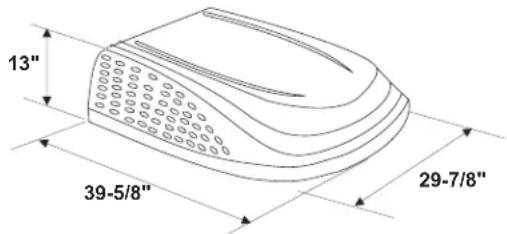
| Weight | Approximately 100 lbs |
| Roof Opening Size | 14-1/4 in x 14-1/4 in |
| Mounting Pattern | 4 bolt pattern |
| Thermostat Compatibility | Comfort Control Center 2 (CCC 2) |
| Heat Pump Option | Available (Model 551816A) |
| Additional Interfaces | Furnace, Energy Management, Auto Generator Start |
Frequently Asked Questions - Blizzard NXT 15K DOMETIC
User questions about Blizzard NXT 15K DOMETIC
0 question about this device. Answer the ones you know or ask your own.
Ask a new question about this device
Download the instructions for your Air-conditioner in PDF format for free! Find your manual Blizzard NXT 15K - DOMETIC and take your electronic device back in hand. On this page are published all the documents necessary for the use of your device. Blizzard NXT 15K by DOMETIC.
USER MANUAL Blizzard NXT 15K DOMETIC
1120 North Main Street
Elkhart, IN 46514
SERVICE CENTER &
DEALER LOCATIONS
Please visit:
www.eDometic.com

INSTALLATION INSTRUCTIONS
| Roof Top Unit | ||||
| Description Model Use With Return Air Grill | ||||
| Air Conditioner 541815A541816A | 3105007.XXXOR3105935.XXX | 3312024.XXX 3311 | 931.XXX | |
| Heat Pump 551816A | ||||
This unit is designed for OEM installation. All initial installations must be approved by Dometic Corporation
WARNING
This manual must be read and understood before installation, adjustment, service, or maintenance is performed. This unit must be installed by a qualified service technician. Modification of this product can be extremely hazardous and could result in personal injury or property damage.
! AVERTISSEMENT
This manual has safety information and instructions to help users eliminate or reduce the risk of accidents and injuries.
RECOGNIZE SAFETY INFORMATION

This is the safety alert symbol. It is used to alert you to personal injury hazards. Obey all safety messages that follow this symbol to avoid possible injury or death.
UNDERSTAND SIGNAL WORDS
A signal word, when used with the safety alert symbol, will identify a safety hazard and its level of risk for personal injury. A signal word, without the safety alert symbol, will be used for property damage messages only.
WARNING
WARNING indicates a hazardous situation which, if not avoided, could result in death or serious injury.
CAUTION
CAUTION, used with the safety alert symbol, indicates a hazardous situation which, if not avoided, could result in minor or moderate injury.
NOTICE
NOTICE is used to address practices not related to personal injury.
WARNING
Read and follow all safety information and instructions to avoid personal injury.
GENERAL INFORMATION
A. Product features or specifications as described or illustrated are subject to change without notice.
B. This Air Conditioner/Heat Pump (hereinafter referred to as the "unit") Is Designed For:
- Installation on a recreational vehicle at the time the vehicle is manufactured.
- Mounting on the roof of a recreational vehicle.
- Roof construction with rafters/joists on minimum of 16 inch centers.
- Minimum of 2 inches and maximum of 5-1/2 inches distance between roof to ceiling of recreational vehicle. Alternate installation methods will allow for roofs more than 5-1/2 inches thick.
C. The ability of this air conditioner to maintain the desired inside temperature depends on the heat gain of the RV.
Some preventative measures taken by the occupants of the RV can reduce the heat gain and improve the performance of the air conditioner. During extremely high outdoor temperatures, the heat gain of the vehicle may be reduced by:
- Parking the RV in a shaded area
- Using window shades (blinds and/or curtains)
- Keeping windows and doors shut or minimizing usage
- Avoiding the use of heat producing appliances
Operation on High Fan/Cooling mode will give optimum or maximum efficiency in high humidity or high outside temperatures.
Starting the air conditioner early in the morning and giving it a "head start" on the expected high outdoor ambient will greatly improve its ability to maintain the desired indoor temperature.
For a more permanent solution to high heat gain, accessories like Dometic outdoor patio and window awnings will reduce heat gain by removing the direct sun. They also add a nice area to enjoy company during the cool of the evening.
D. Condensation
Note: The manufacturer of this unit will not be responsible for damage caused by condensed moisture on ceilings or other surfaces. Air contains moisture and this moisture tends to condense on cold surfaces. When air enters the RV, condensed moisture may appear on the ceiling, windows, metal parts, etc. During normal operation this unit removes moisture from the air. Keeping doors and windows closed when this air conditioner is in operation will minimize condensed moisture on cold surfaces.
SPECIFICATIONS
| Model No. | Nominal Capacity (BTU HR) Cooling | Electrical Rating 120 VAC 60Hz. 1PH | Compressor Rated Load Amps | Compressor Locked Rotor Amps | Fan Motor Rated Load Amps | Fan Motor Locked Rotor Amps | Refrigerant R-410A (Oz.) | Minimum Wire Size* 12 AWG Copper Up to 24' | AC Circuit Protection ***Installer Supplied | Minimum Generator Size** 1 Unit / 2 Units |
| 541815A70X | 13,500 12.0 5 | 8.0 3.0 8.5 18 | 5 20 Amp 3.5 | KW / 5.0 KW | ||||||
| 541816A70X | 15,000 13.2 6 | 0.0 2.8 7.6 29 | 5 20 Amp 3.5 | KW / 5.0 KW | ||||||
| 551816A70X | 15,000 13.2 6 | 0.0 2.8 7.6 29 | 5 20 Amp 3.5 | KW / 5.0 KW |
* For wire length over 24 ft., consult the National Electric Code for proper sizing.
** Dometic Corporation gives GENERAL guidelines for generator requirements. These guidelines come from experiences people have had in actual applications. When sizing the generator, the total power usage of your recreational vehicle must be considered. Keep in mind generators lose power at high altitudes and from lack of maintenance.
*** CIRCUIT PROTECTION: Time Delay Fuse or Circuit Breaker Required.
INSTALLATION INSTRUCTIONS
A. Precautions
WARNING
Improper installation may damage equipment, could endanger life, cause serious injury and/or property damage.
- Read Installation and Operating Instructions carefully before attempting to start this unit installation.
- Dometic Corporation will not be liable for any damages or injury incurred due to failure in following these instructions.
-
Installation must comply with the National Electrical Code ANSI/NFPA-70 and CSA Standard C22.1 (latest edition) and any State or Local Codes or regulations.
-
DO NOT add any devices or accessories to this unit except those specifically authorized in writing by Dometic Corporation.
-
This equipment must be serviced by qualified personnel and some states require these people to be licensed.
B. Choosing Proper Location For The Unit
This unit is specifically designed for installation on the roof of a recreational vehicle (RV). When determining your cooling requirements, the following should be considered:
- Size of RV;
• Window area (increases heat gain);
• Amount of insulation in walls and roof; -
Geographical location where the RV will be used;
• Personal comfort level required. -
For one unit installation: The unit should be mounted slightly forward of center (front to back) and centered from side to side.
-
For two unit installations: Install one unit 1/3 and one unit 2/3's from front of RV and centered from side to side.
It is preferred that the unit be installed on a relatively flat and level roof section measured with the RV parked on a level surface, but up to a 15^ tilt is acceptable.
- After Location Has Been Selected:
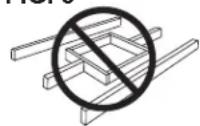
a. Check for obstructions in the area where unit will be installed. See FIG. 1.
FIG. 1
Dimensions Are Nominal
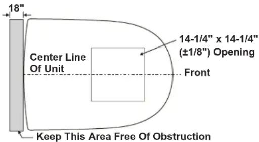
Dimensions Are Nominal
b. The roof must be designed to support 130 pounds when the RV is in motion. Normally a 200 lb. static load design will meet this requirement.
NOTICE
It is the responsibility of the installer of this system to ensure structural integrity of the RV roof. Never create a low spot on the roof where water will collect. Water standing around the unit may leak into the interior causing damage to the product and the RV.
c. Check inside the RV for return air grill obstructions (i.e. door openings, room dividers, curtains, ceiling fixtures, etc.) See FIG. 2.
FIG. 2
Dimensions Are Nominal
Dimensions Are Nominal
C. Roof Preparation
- Opening Requirements - Before preparing the ceiling opening, the type of system options must be decided upon. Read all of the following instructions before beginning the installation.
WARNING
There may be electrical wiring between the roof and the ceiling. Disconnect 120 VAC power cord and the positive (+) 12 VDC terminal at the supply battery. Failure to obey this instruction may create a shock hazard causing death or severe personal injury.
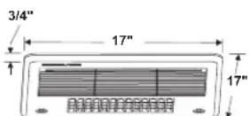
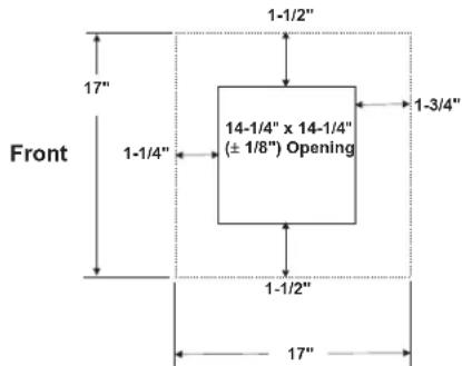
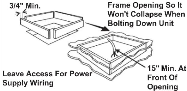
- Mark a 14-1/4" x 14-1/4" (±1/8") square on the roof and carefully cut the opening. The 14-1/4" x 14-1/4" (±1/8") opening is part of the return air system of the unit and must be finished in accordance with ANSI A119.2.
- Using the roof opening as a guide, cut the matching hole in the ceiling.
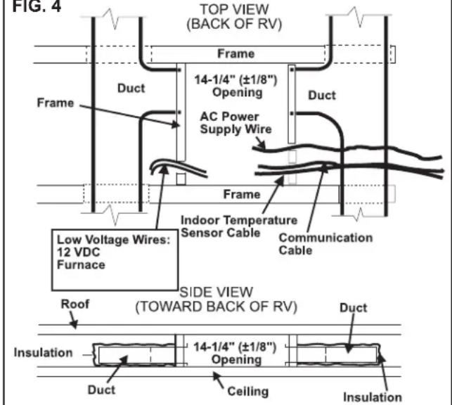
- The opening created must be framed to provide adequate support and prevent air from being drawn from the roof cavity. Framing stock 3/4" or more in thickness must be used. Remember to provide an entrance hole for power supplies, (indoor temperature sensor cable (if applicable), 4 conductor communication cable, and furnace wiring (if applicable).
FIG. 3
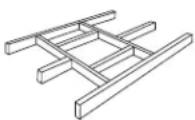
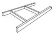
Do Not Cut Roof Structure Or Rafters
Good-Rafters Supported By Cross Beams
Good Location-
Between Roof
Rafters
NOTICE
It is the responsibility of the installer of this system to ensure structural integrity of the RV roof. Never create a low spot on the roof where water will collect. Water standing around the unit may leak into the interior causing damage to the product and the RV.
D. Air Distribution Duct System Sizing & Design (See Chart On Page 6)
NOTICE
It is the responsibility of the installer to insure the duct work will not collapse or bend during and after the installation. Dometic Corporation will not be liable for roof structural or ceiling damage due to improperly insulated, sealed or collapsed duct work.
The Installer of this system must design the air distribution system for their particular application. Several requirements for this system MUST be met for the unit to operate properly. These requirements are as follows:
1. The duct material must meet or exceed any agency or RVIA Standard that may be in existence at the time the RV is produced.
2. All discharge air ducts must be properly insulated to prevent condensation from forming on their surfaces or adjacent surfaces during operation of the unit. This insulation must be R-7 minimum.
FIG. 4
-
Ducts and their joints must be sealed to prevent condensation from forming on adjacent surfaces during operation of the unit.
-
Return air openings must have 40 square inches minimum free area including the filter.
-
Return air to the unit must be filtered to prevent dirt accumulation on unit cooling surface.
-
Air Distribution System Installation
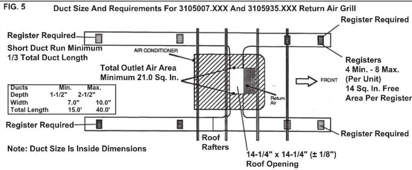
a. Dometic Corporation recommends the basic configuration shown on page 6, for installing this system. We have found by testing, that this configuration works best in most applications of this system. It is the responsibility of the installer of this system to review each RV floor plan and determine the following:
- Duct size
- Duct layout
- Register size
- Register location
• Thermostat location
- Indoor Temperature Sensor Location
These items must be determined in conjunction
with the Air Distribution Duct System Sizing and
Design Requirements listed in the chart below.
Important: Alternate configurations and methods may be used which still allow the unit to operate properly; however, these alternate configurations and methods must be approved by Dometic Corporation in writing. The following instructions are based upon the use of Return Air Grill Kits 3105007.XXX & 3105935.XXX.
Air Distribution Duct Sizing & Design Chart For Ducted Applications
| Return Air Grill Kit3105007.XXX3105935.XXX | |
| Roof Cavity Depth 2.0 In. Min. - 5-1/2 In. | Max. |
| Duct Cross Sectional Area 21.0 Sq. In. | Min. |
| Duct SizeDepthWidthTotal Duct LengthDuct Length (short run) | 1-1/2 In. Min. - 2-1/2 In. Max.7.0 In. Min. - 10.0 In. Max.15.0 Ft. Min. - 40.0 Ft. Max.1/3 Total Duct Length |
| Register Requirements per A/C UnitNumber RequiredRegister Free Air AreaDistance From Duct EndDistance From Elbow | 4 Min. - 8 Max.14.0 Sq. In.5.0 In. Min. - 8.0 In. Max.15.0 In. |
| Total System Static Air PressureBlower at High Speed,Filter & Grill In Place | 0.55 - 1.10 In. W.C. 541815 Series0.70 - 1.10 In. W.C. 541816 Series |
Note: Duct sizes listed are inside dimensions.
E. Wiring Requirements
- Route a 120 VAC supply wire from the time delay fuse or circuit breaker box to the roof opening. It must be a two circuit with ground solid copper wire with non metallic sheath. The proper size wire can be determined from chart on page 3.
a. This supply wire must be located in the front portion of the 14-1/4" x 14-1/4" (±1/8") opening.
b The power MUST be on an appropriately sized separate time delay fuse or circuit breaker. The proper size protection can be determined from the chart on page 3.
c. Make sure at least 15" of supply wire extends into the roof opening. This insures an easy connection at the unit electrical cord.
d. Wiring must comply with the National Electrical Code ANSI/NFPA -70 and CSA Standard C22.1 (latest edition) and any State or Local Codes or regulations.
e. Protect the wire where it passes into the opening with approved method. See paragraph "d" above.
- Route a dedicated 12 VDC supply wire (18-22 AWG) from the RV's converter (filtered side) or battery to the roof opening.
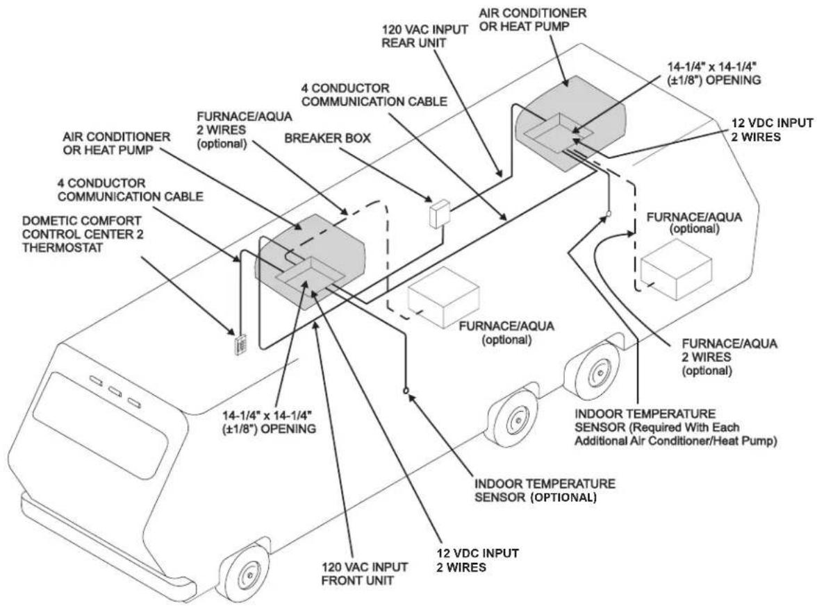
Note: When a Comfort Control Center 2 (hereinafter referred to as CCC 2) thermostat is being installed with more than 2 zones, route a dedicated 12 VDC supply wire (18-22 AWG) to zone 1 and zone 3 roof opening.
a. This supply wire must be located in the front portion of the 14-1/4" x 14-1/4" (±1/8") opening.
b. Make sure that at least 15" of supply wire extends into the roof opening.
-
Route an indoor temperature sensor (optional) from the roof opening to the indoor temperature sensor location. The 2 pin connector end goes to the roof opening. See indoor temperature sensor installation instructions for proper sensor location.
-
Route a 4 conductor communication cable from the CCC 2 thermostat mounting position into the 14-1/4" x 14-1/4" (±1/8") roof opening. Make sure that at least 15" of the wire extends into the roof opening and 6" extends from the wall at the mounting position of the CCC 2 thermostat. See Section F-1.
Important: When more than one unit is being installed (additional zones) with the CCC 2 thermostat, an additional 4 conductor communication cable must be routed to each additional unit 14-1/4" x 14-1/4" (±1/8") roof opening. Make sure at least 15" of the wire extends into the roof opening. See FIG. 32.
-
If system includes a gas furnace, route two 18 gauge thermostat wires from the furnace to the roof opening of the unit that will control it. If more than one furnace is to be used, route the second set of thermostat wires to the second unit. Make sure that 6" of wire extends into the opening.
-
If an Energy Management System (load shed feature) is to be used with the control, two wires must be routed to the roof opening of the zone to be managed. The signal required for this function is normally an open relay contact. When the EMS calls for the compressor to shut off, the relay contacts should close. Make sure at least 15" of the EMS wire extends into the roof opening.
-
If an Automatic Generator Start (AGS) kit will be installed, an additional 4 conductor communication cable must be routed from the last unit to the location of the AGS kit. Follow AGS kit instructions for installation.
F. Choosing Thermostat Location
- CCC 2 Location
a. If the system is to be used without an indoor temperature sensor, the proper location of the CCC 2 thermostat is very important to ensure that it will provide a comfortable RV temperature. Observe the following rules when selecting a location:
- Locate the CCC 2 thermostat 54" above the floor.
• Install the CCC 2 thermostat on a partition, not on an outside wall. - NEVER expose it to direct heat from lamps, sun or other heat producing items.
- Avoid locations close to doors that lead outside, windows or adjoining outside walls.
- Avoid locations close to supply registers and the air from them.
b. If the system is to be used with an Indoor Temperature Sensor in ALL zones, the CCC 2 thermostat may be mounted anywhere that is convenient in the coach. Try to avoid hard to reach and hard to see areas.
- Refer to the instructions provided with the Indoor Temperature Sensor for details of installation.
G. Thermostat, Indoor Temperature Sensor, & Thermostat Communication Cable Installation
- CCC 2 Thermostat
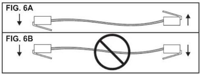
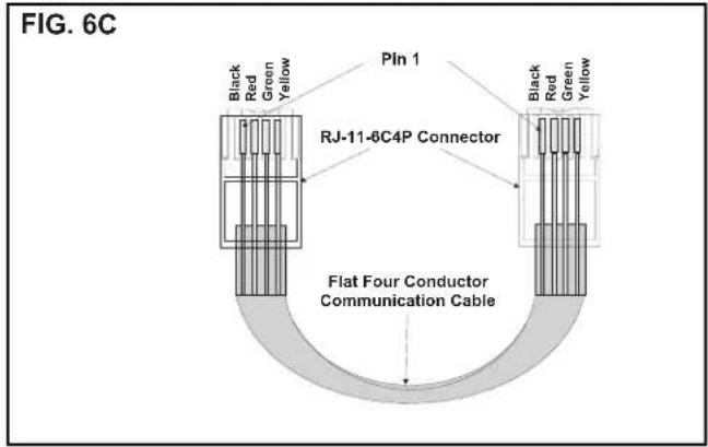
a. The previously run communication cable (4 conductor telephone cable) must be terminated with two (2) RJ-11-6C4P telephone connectors. Refer to the crimp tool manufacturer for crimping instructions. See FIG. 6A & 6C.
Important: RJ-11-6C4P connectors must be installed as shown in FIG. 6A & 6C.
b. Choose the shortest, most direct route from the 14-1/4" x 14-1/4" (±1/8") opening to the selected CCC 2 thermostat location. Leave 6" of cable extending through the wall.
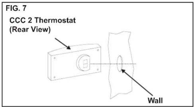
c. Route the communication cable through the 2" diameter hole in the wall required for the thermostat. See FIG. 7.
d. Optional Indoor Temperature Sensor
i. Refer to the instructions provided with the indoor temperature sensor for details of installation.
e. CCC 2 Thermostat Installation
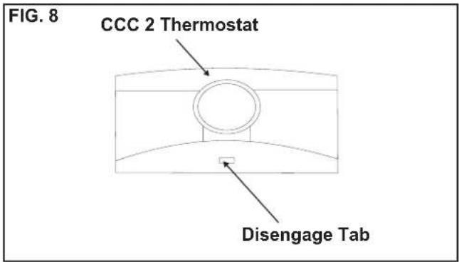
i. Carefully separate the thermostat base plate from the thermostat cover. Insert a small screw driver into the slot on bottom of thermostat and disengage the tab. See FIG. 8.
ii. Insert the 4 conductor communication cable through the hole in base plate. Align thermostat base plate with hole in wall. Make sure base plate is level and attach base plate to wall using the 4 supplied screws.
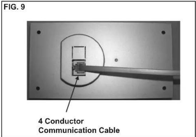
iii. Insert the 4 conductor communication cable connector (RJ-11-6C4P) into the connector on the back of the thermostat. See FIG. 9.
iv. Align the thermostat with the back plate and snap into position.
H. Placing The Unit On The Roof
WARNING
Personal injury hazard. This unit weighs approximately 100 pounds. To prevent back injury, use a mechanical hoist to place unit on roof. Failure to obey this warning could cause severe personal injury.
- Remove the unit from the carton and discard carton.
- Place the unit on the roof.
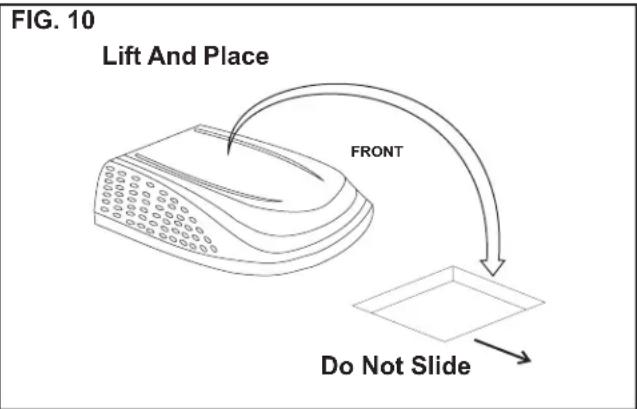
- Lift and place the unit over the prepared opening using the gasket on the unit as a guide. See FIG. 10.
NOTICE
Property damage hazard. Do not slide the unit. Failure to obey this warning may damage the neoprene gasket attached to the bottom and create a leaky installation.
- Place the return air cover kit inside the RV. This box contains mounting hardware for the unit and will be used inside the RV.
This completes the outside work. Minor adjustments can be done from inside the RV if required.
I. Installing The Unit
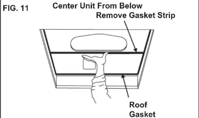
- Check gasket alignment of the unit over the roof opening and adjust if necessary. Unit may be moved from below by slightly lifting. See FIG. 11. When installing 3105007.XXX or 3105935.XXX return air kit, remove gasket strip from bottom of base pan and discard.
- Remove return air cover and ceiling template from carton.
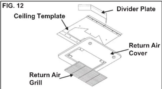
-
All models listed in this manual will use a four (4) bolt pattern for installing the return air cover kit. These bolts are furnished in part number 3100895.006 (bolt kit) and is purchased separately.
-
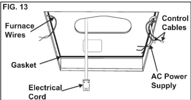
Reach up into the return air opening and pull the unit electrical cord down. See FIG. 13.
-
Hold the ceiling template up to the 14-1/4" x 14-1/4" (±1/8") opening. Be sure the large plate faces the rear of the RV.
-
Start each mounting bolt through the ceiling template and up into the unit base pan by hand. Install wood screw in each end of the ceiling template. This insures a tight fit of the return air cover to ceiling. See FIG. 14.
FIG. 14 Front of Vehicle
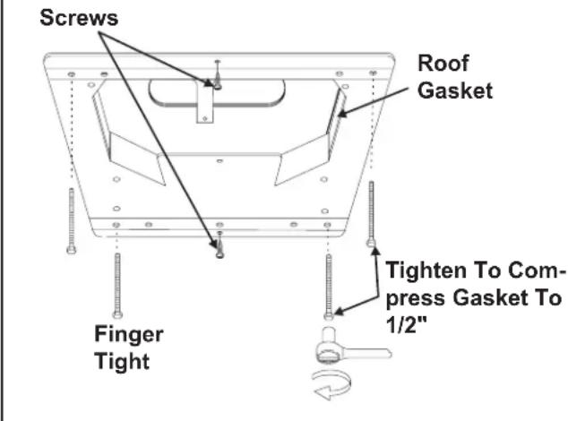
Evenly tighten the four mounting bolts to a torque of 40 to 50 inch pounds. This will compress the roof gasket approximately 1/2". The bolts are self locking so further tightening is not necessary. See FIG. 14.
NOTICE
If bolts are left loose there may not be an adequate roof seal or if over tightened, damage may occur to the unit base or ceiling template. Tighten to torque specifications listed in this manual.
- Installation of Divider Plate
a. Measure the ceiling to roof thickness:
- If distance is 2.0" - 3-3/4", remove perforated tab from divider plate.
- If distance is 3-3/4" - 5-1/2", remove no tabs.
b. Remove the backing paper from double sided tape located on ceiling template. See FIG. 15.
FIG. 15 Backing Paper
natural_image
Technical line drawing of a mechanical component with mounting holes and a central support (no text or symbols)
c. Place divider plate up to bottom of the unit base pan firmly. The foam tape on the divider plate must seal to bottom of base pan. See FIG. 16.
NOTICE
Improper installation and sealing of divider plate will cause the compressor to quick cycle on the cold control. This may result in fuse or circuit breaker opening and/or lack of cooling.
FIG. 16
natural_image
Technical line drawing of a mechanical component with two upward-pointing arrows indicating assembly or alignment (no text or symbols present)Push Divider Plate Firmly Onto Base Pan
Note: The adhesive on the insulation is extremely sticky. Be sure the part is located where desired before pressing into place.
d. With slight pressure push the divider plate against the double sided tape on the ceiling template.
e. Locate the 1/8" x 7" x 18" self-adhesive insulation supplied with the return air kit. Remove the backing paper from the insulation and carefully stick onto the ceiling template divider panel. See FIG. 17.
FIG. 17
Place Insulation In Position
(Do Not Cover Unit Rating Plate)
Foam Tape
- Excess width is intended to seal the divider plate to the sides of the 14-1/4" x 14-1/4" (±1/8") opening. This is to help prevent cold air discharge from circulating into the unit return air opening.
- If the insulation is too high, stick excess height of insulation to the unit base pan. Do not cover up unit rating plate.
J. Wiring The System
Reach up into the return air opening and pull the remaining wires down. See FIG. 13.
- Low Voltage Wire Connections
NOTICE
Disconnect the positive (+) 12 VDC terminal at the supply battery. Damage to equipment could occur if the 12 VDC is not shut off.
a. Connect the previously run 12 VDC wires to the red and black wires protruding from the unit return air opening. Connect +12 VDC to the red wire; -12 VDC to the black wire.
b. Connect the previously run furnace thermostat wires (if applicable) to the blue wires protruding from the return air opening. The polarity of these connections does not matter.
c. Terminate the 4 conductor communication cable(s) protruding into the 14-1/4" x 14-1/4" (±1/8") roof opening. The cable(s) must be terminated with a telephone RJ-11-6C4P connector. Refer to the crimp tool manufacturer for crimping instructions.
Important: RJ-11-6C4P connectors must be installed as shown in FIG. 6A & 6C.
d. Plug the 4 conductor communication cable into the RJ-11-6C4P telephone coupler protruding from the return air opening.
e. Plug the indoor temperature sensor cable (if applicable) into the white 2 pin connector protruding from the return air opening.
f. Connect the previously run Energy Management System wires (if applicable) to the yellow wires protruding from the return air opening. The polarity of these connections does not matter.
g. If an automatic generator start (AGS) kit is installed, follow installation instructions furnished with AGS kit.
2. 120 VAC Power Supply Connection
WARNING
Disconnect 120 VAC. Failure to obey these instructions could create a shock hazard causing death or severe personal injury.
Note: Wiring must comply with the National Electrical Code ANSI/NFPA-70 and CSA Standard C22.1 (latest edition) and any State or Local Codes or regulations.
WARNING
This product is equipped with a 3 wire (grounded) system for protection against shock hazard. Make sure that the unit is wired into a properly grounded 120 VAC circuit and the polarity is correct. Failure to do so could result in death, personal injury or damage to the equipment.
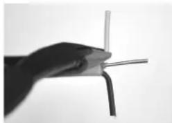
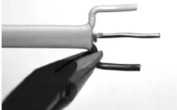
a. Carefully strip and prepare wires as shown in FIGS. 18-22.
FIG. 18
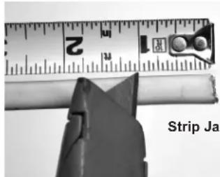
Strip Jacket To 1"
FIG. 19
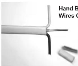
Hand Bend White And Black Wires Outward 90°
FIG. 20
Use Tip Of Pliers To HOLD Wire In Place While Hand Bending Wire At 90°
natural_image
Close-up of a hand holding a thin wire with a curved tip, no visible text or symbols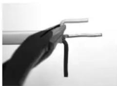
natural_image
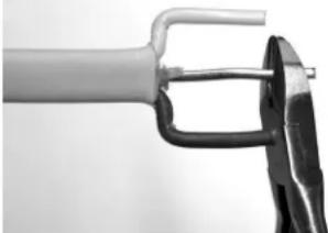
Close-up of a hand holding two wires (no text or symbols visible)FIG. 21
Repeat With Other Wire
natural_image
Close-up of a metallic electrical cable with two leads, showing internal wires (no text or symbols visible)FIG. 22
Trim Ground Wire To Length Of Outer Wires.
natural_image
Close-up of a tool gripping a mechanical part, no visible text or symbolsb. Hold the clear strain relief cover with bottom facing upward as shown in FIG. 23.
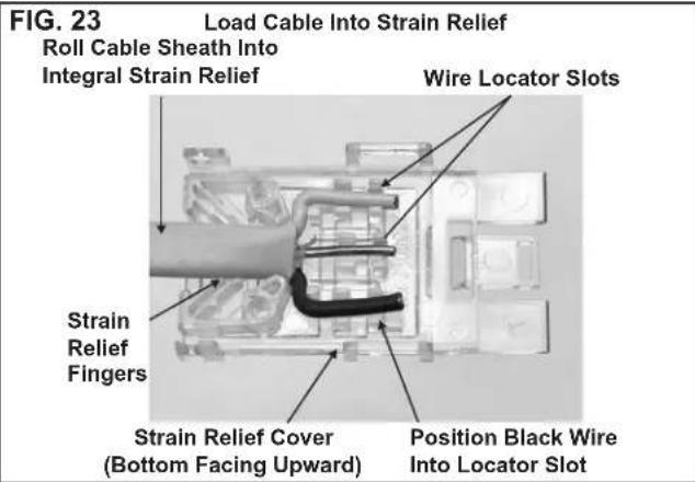
c. Lay wire into locator slots, making sure the black wire is placed into the polarization slot as shown in FIG. 23.
d. Press the cable sheath into the integral strain relief slot as shown in FIG. 23. Trimming of ground wire and possibly others will be necessary. Wires must not extend beyond the locators as shown in FIG. 24.
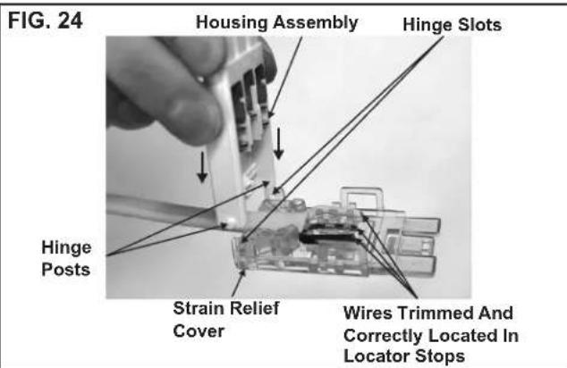
e. While holding the strain relief cover, position the housing's hinge posts into the hinge slots and press down until both lock into place as shown in FIG. 24.
f. Close the strain relief cover and housing by hand. Squeeze the top and bottom closed with tongue and groove pliers as shown in FIG. 25. Pliers must be a minimum of 10" long. Squeeze firmly on both sides, squarely across the connector between ribs A and B to ensure wires seat completely into slots.
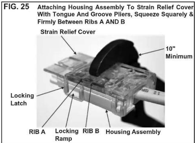
g. Inspect the connector to ensure the wires have been properly engaged into the housing assembly contacts. A properly terminated wire is fully seated into its proper slots with no significant bow of the cover. If the wires extend past the insulation stops, the wires must be re-terminated with a NEW CONNECTOR. Once the cover has been closed the connector cannot be re-used. Failure to comply with this procedure may result in the failure of the connector.
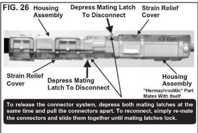
h. Mating and un-mating the completed connector is illustrated in FIG. 26.
K. Installing Decorative Inside Cover
- Remove the return air grill from the return air cover.
- Place the return air cover up to the ceiling template.
- Install cover to template with #8 x 3/8" blunt point Phillips head screws provided (6 required).
- Reinstall filter return air grill into return air cover. Align tabs with mating notches and snap into place.
- Install two hole plugs into screw holes in back of return air cover. See FIG. 27.
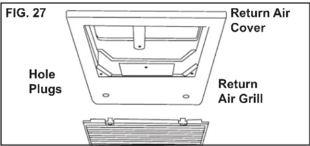
- This completes the unit installation.
L. System Configuration, Reset & Check Out
Now that the system is installed, it is necessary to do a system configuration, reset and check out.
1. Electronic Control Configuration
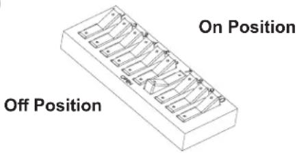
Depending on the equipment options installed by the recreational vehicle manufacturer, the appropriate dip switches will need to be switched to the "ON" position. Placing the switch in the "ON" position selects that option. See FIGS. 28, 29 & 30.
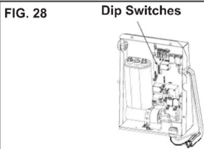
Note: Most dip switches are in the "OFF" position when shipped from the factory. The models listed in this manual will have the furnace dip switch set to the "ON" position. If no furnace will be connected to the unit the furnace dip switch must be placed in the "OFF" position. To gain access to the dip switches, the outside plastic shroud must be removed from the unit. Next remove the electrical box cover. The electrical box will be on the street side of the RV after installation. See FIGS. 28, 29 & 30.
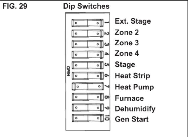
a. Ext. Stage - Ext. Stage is not used on this unit. Leave in the "OFF" position.
b. Zone selection - Each CCC 2 thermostat can have up to 4 zones. When only one unit is installed it becomes Zone 1 and no dip switch setting is required. Each additional unit must be assigned a zone (2 through 4). Each unit must have a different zone setting.
c. Stage selection - Stage is not used on this unit. Leave in the "OFF" position.
d. Heat Strip - Heat strip is not used on this unit.
Leave in the "OFF" position.
e. Heat Pump - If unit is a heat pump, the heat pump dip switch #7 is set to the "ON" position from the factory.
f. Furnace - The furnace dip switch #8 is set to the "ON" position from the factory. If no Furnace/Aqua heat system has been connected to this unit, the furnace dip switch must be placed in the "OFF" position.
g. Dehumidify - Dehumidify is not used on this unit. Leave in the "OFF" position.
h. Gen start selection - Leave in the "OFF" position.
i. Replace the unit electrical box cover and out side plastic shroud.
j. Repeat this procedure for each additional zone.
FIG. 30
2. System Reset
After setting the dip switches in the electronic control, do a system reset.
a. Reconnect the 12 VDC and 120 VAC power supplies.
b. Make sure the CCC 2 thermostat is in the OFF mode.
c. Simultaneously press the MODE and ZONE buttons. The LCD will display "IniT" and all available zones.
d. Release the MODE and ZONE buttons.
e. Press the ON/OFF button to exit system set up.
f. When a dip switch is turned on after initial configuration, a system reset will need to be done before the CCC 2 thermostat will recognize the updated selection.
3. System Checkout
Verify that all features of the installed system work. See CCC 2 thermostat Operating Instructions or User's Guide. Check fan speeds, cooling mode, and furnace mode (if applicable). If the features do not work disconnect the 12 VDC and 120 VAC power supplies and verify that all wiring is correct and that the correct dip switches have been turned on.
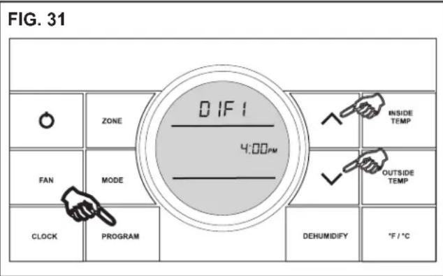
M. Furnace/Aqua Temperature Differential Setting
This system can be configured to operate using an ON/OFF differential of either 1 degree F. or 2 degree F. See FIG. 31.
- To set the differential, simultaneously press the
PROGRAM button and the up button on the CCC 2 thermostat. "diF1" will appear in the display while the buttons are pressed. See FIG. 31. To set the 2 degree differential, simultaneously press the PROGRAM button and the down button. "diF2" will appear in the display while the buttons are pressed.
N. General Information
- Frost Formation On Cooling Coil
Frost on a small portion of the coil is not un usual. Under certain conditions, ice may form on the evaporator coil. This is indicated by very cold output at very low air speed and the icing can be seen through the air inlet hole with the filter removed. If this should occur, inspect the filter and clean if dirty. Make sure air vents are open and not obstructed. Units have a greater tendency to frost when the outside temperature is relatively low. This may be prevented by adjusting the thermostat control knob to a warmer setting (counter clockwise). Should frosting continue, operate on any FAN ONLY setting until the cooling coil is free of frost; then resume nor mal operation. If frost condition persist, contact your local service center for assistance.
- Heat Gain
The ability of this air conditioner to maintain the desired inside temperature depends on the heat gain of the RV. Some preventative measures taken by the occupants of the RV can reduce the heat gain and improve the performance of the air conditioner. During extremely high outdoor temperatures, the heat gain of the RV can may be reduced by:
a. Parking the RV in a shaded area
b. Using window shades (blinds and/or curtains)
c. Keeping windows and doors shut or minimizing usage
d. Avoid the use of heat producing appliances
Operation on High Fan/Cooling mode will give optimum or maximum efficiency in high humidity or high outside temperatures. Starting the air conditioner early in the morning and giving it a “head start” on the expected high outdoor ambient will greatly improve its ability to maintain the desired indoor temperature. For a more permanent solution to high heat gain, acces sories like Dometic outdoor patio and window awnings will reduce heat gain by removing the direct sun. They also add a nice area to enjoy company during the cool of the evening.
- Condensation
The manufacturer of this unit will not be responsible for damage caused by condensation forming on ceilings, windows, or other surfaces. Air contains water vapor which condenses when temperature of a surface is below Dew point. During normal operation this unit is designed to remove a certain amount of moisture from the air, depending on the size of the space being conditioned. Keeping doors and windows closed when this air conditioner is in operation will greatly reduce the chance of condensation forming on interior surfaces.
- Air Distribution
Each A/C unit operating in cool mode, must have a minimum of 2 distribution vents, or the quick cool vent and one vent open, to avoid the risk of freezing coils and improper function.
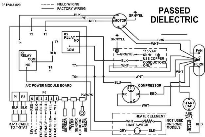
FIG. 32
WIRING DIAGRAM
541815A & 541816A Wiring Diagram
flowchart
graph TD
    A["3312441.029"] --> B["FIELD WIRING"]
    A --> C["FACTORY WIRING"]
    B --> D["K1 RELAY COM NO"]
    C --> E["K2 RELAY NO COM"]
    D --> F["T1"]
    D --> G["T2"]
    D --> H["T3"]
    E --> I["T4"]
    E --> J["T5"]
    E --> K["T6"]
    E --> L["T7"]
    E --> M["T8"]
    E --> N["T9"]
    E --> O["T10"]
    E --> P["T11"]
    E --> Q["T12"]
    E --> R["T13"]
    E --> S["T14"]
    E --> T["T15"]
    E --> U["T16"]
    E --> V["T17"]
    E --> W["T18"]
    E --> X["T19"]
    E --> Y["T20"]
    E --> Z["T21"]
    E --> AA["T22"]
    E --> AB["T23"]
    E --> AC["T24"]
    E --> AD["T25"]
    E --> AE["T26"]
    E --> AF["T27"]
    E --> AG["T28"]
    E --> AH["T29"]
    E --> AI["T30"]
    E --> AJ["T31"]
    E --> AK["T32"]
    E --> AL["T33"]
    E --> AM["T34"]
    E --> AN["T35"]
    E --> AO["T36"]
    E --> AP["T37"]
    E --> AQ["T38"]
    E --> AR["T39"]
    E --> AS["T40"]
    E --> AT["T41"]
    E --> AU["T42"]
    E --> AV["T43"]
    E --> AW["T44"]
    E --> AX["T45"]
    E --> AY["T46"]
    E --> AZ["T47"]
    E --> BA["T48"]
    E --> BB["T49"]
    E --> BC["T50"]
    E --> BD["T51"]
    E --> BE["T52"]
    E --> BF["T53"]
    E --> BG["T54"]
    E --> BH["T55"]
    E --> BI["T56"]
    E --> BJ["T57"]
    E --> BK["T58"]
    E --> BL["T59"]
    E --> BM["T60"]
    E --> BN["T61"]
    E --> BO["T62"]
    E --> BP["T63"]
    E --> BQ["T64"]
    E --> BR["T65"]
    E --> BS["T66"]
    E --> BT["T67"]
    E --> BU["T68"]
    E --> BV["T69"]
    E --> BW["T70"]
    E --> BX["T71"]
    E --> BY["T72"]
    E --> BZ["T73"]
    E --> CA["T74"]
    E --> CB["T75"]
    E --> CC["T76"]
    E --> CD["T77"]
    E --> CE["T78"]
    E --> CF["T79"]
    E --> CG["T80"]
    E --> DH["T81"]
    E --> DI["T82"]
    E --> DJ["T83"]
    E --> DK["T84"]
    E --> DL["T85"]
    E --> DV["T86"]
    E --> DW["T87"]
    E --> DX["T88"]
    E --> DXT["XLM/HEATER ELEMENT"]

    subgraph PASSED DIELECTRIC
        direction TB
        direction LR
        direction SC
        direction CV
        direction DD
        direction DE
        direction FL
        direction DG
        direction DV
        direction DW
        direction DR
        direction CS
        direction SC
        direction CV
        direction CV
        direction DC
        direction DB
        direction DB
        direction DC
        direction DB
        direction DC
        direction DB
        direction DC
        direction DB
        direction DB
        direction DC
        direction DB
        direction DB
        direction DC
        direction DB
        direction DB
        direction DC
        direction DB
        direction DB
        direction DC
        direction DB
        direction DB
        direction DC
        direction DB
        direction DB
        direction DC
        direction DB
        direction DB
        direction DC
        direction DB
        direction DB
        direction DC
        direction DB
        direction DC
        direction DB
        direction DB
        direction DC
        direction DB
        direction DB
        direction DC
        direction DB
        direction DB
        direction DC
        direction DB
        direction DB
        direction DC
        direction DB
        direction DB
        direction DC
        direction DB
        direction DB
        direction DC
        direction DB
        direction DB
        direction TC
        direction DB
        direction DB
        direction TC
        direction DB
        direction DB
        direction TC
        direction DB
        direction DB
        direction TC
        direction DB
        direction DB
        direction TC
        direction DB
        direction DB
        direction TC
        direction DB
        direction DB
        direction TC
        direction DB
        direction DB
        direction TC
        direction DB
        direction DB
        direction TC
        directionDB
        directionDB
        directionDB
        directionDB
        directionDB
        directionDB
        directionDB
        directionDB
        directionDB
        directionDB
        directionDB
        directionDB
        directionDB
        directionDB
        directionDB
        directionDB
        directionDB
        directionDB
        directionDB
        directionDB
        directionDB
        directionDB
        directionalDB
        directionalDB
        directionalDB
        directionalDB
        directionalDB
        directionalDB
        directionalDB
        directionalDB
551816A Wiring Diagram
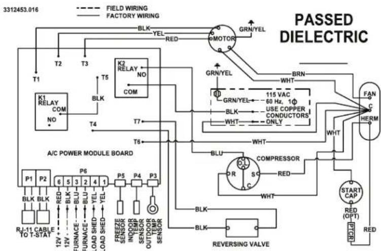
flowchart
graph TD
    A["FIELD WIRING"] --> B["FACTORY WIRING"]
    B --> C["K1 RELAY COM NO"]
    C --> D["T2"]
    D --> E["T3"]
    E --> F["T5"]
    F --> G["K2 RELAY NO COM"]
    G --> H["T4"]
    H --> I["T6"]
    I --> J["T7"]
    J --> K["GRN/YEL"]
    K --> L["BRN"]
    L --> M["WHT"]
    M --> N["115 VAC 60 Hz, 1Φ USE COPPER CONDUCTORS ONLY"]
    N --> O["WHT"]
    O --> P["FAN C HERM"]
    P --> Q["START CAP RED (OPT) RED"]
    Q --> R["REVERSING VALVE"]
    R --> S["COMPRESSOR"]
    S --> T["SC"]
    T --> U["R"]
    U --> V["BLU"]
    V --> W["P5"]
    W --> X["P4"]
    X --> Y["P3"]
    Y --> Z["P6"]
    Z --> AA["P1"]
    AA --> AB["BLK BLK"]
    AB --> AC["RJ-11 CABLE TO T-STAT 12V + 12V - BLK BLU BLU BLU YEL LOAD SHED YEL LOAD SHED YEL FREEZE SENSOR INVOIR SENSOR OUTDOOR TEMP SENSOR SENSOR REVERSING VALVE"]
    style A fill:#f9f,stroke:#333
    style B fill:#f9f,stroke:#333
    style C fill:#ccf,stroke:#333
    style D fill:#ccf,stroke:#333
    style E fill:#ccf,stroke:#333
    style F fill:#ccf,stroke:#333
    style G fill:#ccf,stroke:#333
    style H fill:#ccf,stroke:#333
    style I fill:#ccf,stroke:#333
    style J fill:#ccf,stroke:#333
    style K fill:#ccf,stroke:#333
    style L fill:#ccf,stroke:#333
    style M fill:#ccf,stroke:#333
    style N fill:#ccf,stroke:#333
    style O fill:#ccf,stroke:#333
    style P fill:#ccf,stroke:#333
    style Q fill:#ccf,stroke:#333
    style R fill:#ccf,stroke:#333
    style S fill:#ccf,stroke:#333
    style T fill:#ccf,stroke:#333
    style U fill:#ccf,stroke:#333
    style V fill:#ccf,stroke:#333
    style W fill:#ccf,stroke:#333
    style X fill:#ccf,stroke:#333
    style Y fill:#ccf,stroke:#333
    style Z fill:#ccf,stroke:#333
    style AA fill:#ccf,stroke:#333
    style AB fill:#ccf,stroke:#333
    style AC fill:#ccf,stroke:#333
    style AD fill:#ccf,stroke:#333
    style AE fill:#ccf,stroke:#333
    style AF fill:#ccf,stroke:#333
    style AG fill:#ccf,stroke:#333
    style AH fill:#ccf,stroke:#333
    style AI fill:#ccf,stroke:#333
    style AJ fill:#ccf,stroke:#333
    style AK fill:#ccf,stroke:#333
    style AL fill:#ccf,stroke:#333
    style AM fill:#ccf,stroke:#333
    style AN fill:#ccf,stroke:#333
    style AO fill:#ccf,stroke:#333
    style AP fill:#ccf,stroke:#333
    style AQ fill:#ccf,stroke:#333
    style AR fill:#ccf,stroke:#333
    style AS fill:#ccf,stroke:#333
    style AT fill:#ccf,stroke:#333
    style AU fill:#ccf,stroke:#333
    style AV fill:#ccf,stroke:#333
    style AW fill:#ccf,stroke:#333

- SERVICE CENTER &
- DEALER LOCATIONS
- Please visit:
- INSTALLATION INSTRUCTIONS
- WARNING
- ! AVERTISSEMENT
- RECOGNIZE SAFETY INFORMATION
- UNDERSTAND SIGNAL WORDS
- CAUTION
- NOTICE
- GENERAL INFORMATION
- Condensation
- Precautions
- Choosing Proper Location For The Unit
- Roof Preparation
- Air Distribution Duct System Sizing & Design (See Chart On Page 6)
- Wiring Requirements
- Choosing Thermostat Location
- Thermostat, Indoor Temperature Sensor, & Thermostat Communication Cable Installation
- Placing The Unit On The Roof
- Installing The Unit
- Wiring The System
- Disconnect the positive (+) 12 VDC terminal at the supply battery. Damage to equipment could occur if the 12 VDC is not shut off.
- Important: RJ-11-6C4P connectors must be installed as shown in FIG. 6A & 6C.
- Disconnect 120 VAC. Failure to obey these instructions could create a shock hazard causing death or severe personal injury.
- Installing Decorative Inside Cover
- System Configuration, Reset & Check Out
- Electronic Control Configuration
- System Reset
- System Checkout
- Furnace/Aqua Temperature Differential Setting
- General Information
- WIRING DIAGRAM
- 541815A & 541816A Wiring Diagram
Brand : DOMETIC
Model : Blizzard NXT 15K
Category : Air-conditioner