
Airhandler - Air-conditioner DOMETIC - Free user manual and instructions
Find the device manual for free Airhandler DOMETIC in PDF.

| Product Type | Chilled water air handler (fan coil unit) for marine HVAC systems |
| Brand | Dometic |
| Model Series | AT, ATL, ATV, ABL, Blowthrough, Gold Series (AU), Fresh Air Make Up (FAMU), SMU |
| Cooling Capacity Range | 4,000 to 36,000 BTU/hr (models available) |
| Power Supply | 230VAC (field-configurable for 208VAC) or DC blower option; unit-specific voltage per label |
| Main Functions | Cooling (chilled water), heating (reverse cycle or electric heat), dehumidification (FAMU models) |
| Blower Type | Standard AC blower or DC blower (quieter option) |
| Duct Connection | Round or oval mount rings; duct sizes from 4" to 8" diameter depending on capacity |
| Mounting | Deck-mounted or suspended using provided brackets; must be level and secure in a semi-conditioned space |
| Water Connections | 3/4" or 1" full-flow ball valves (customer supplied); flexible reinforced hose with double stainless steel clamps |
| Control Interface | Thermostat display (wall-mount or remote); SMU or Standard MU controls for FAMU models |
| Sensors | Water temperature sensor (on copper supply pipe), air temperature sensor (return air or discharge), change-over switch (COS) for hot/cold water detection |
| Electric Heat Option | Built-in electric resistance heater with automatic and manual thermal overloads (if equipped) |
| Condensate Drain | Two drain connections (port/starboard); 5/8" ID reinforced hose; must be routed downhill to overboard or sump |
| Filter | Return-air grille filter or unit-mounted; clean/replace monthly; reusable or pleated types |
| Maintenance Intervals | Monthly: check/replace filter. Quarterly: inspect condensate drains with water test. Yearly: check freeze protection, inspect valve gears, verify sensor placement |
| Safety Features | Grounding required; thermal overloads (auto and manual resets); caution against electrical shock, burns, moving parts; avoid explosive fumes |
| Compliance | Designed per ABYC standards (American Boat and Yacht Council) |
| Accessories | Breathe Easy air purifier (UV+PCO), transition boxes, plenums, oval duct rings, vibration isolators |
| Spare Parts | Bulb (for Breathe Easy: 4210800 for models 6-12, 4210802 for 18-24), filters, blower motors, capacitors, valve actuators, sensors |
Frequently Asked Questions - Airhandler DOMETIC
User questions about Airhandler DOMETIC
0 question about this device. Answer the ones you know or ask your own.
Ask a new question about this device
Download the instructions for your Air-conditioner in PDF format for free! Find your manual Airhandler - DOMETIC and take your electronic device back in hand. On this page are published all the documents necessary for the use of your device. Airhandler by DOMETIC.
USER MANUAL Airhandler DOMETIC
Installation, Operation & Maintenance Manual
Dometic
Rev. 20171013
L-2812 English
PN: 0880268
www.dometic.com
COPYRIGHT © 2007-2017 Dometic Corporation. All Rights Reserved.
No part of this publication may be reproduced, translated, stored in a retrieval system, or transmitted in any form or by any means electronic, mechanical, photocopying, recording or otherwise without prior written consent by Dometic Corporation. Every precaution has been taken in the preparation of this manual to ensure its accuracy. However, Dometic Corporation assumes no responsibility for errors and omission. Neither is any liability assumed for damages resulting from the use of this product and information contained herein.
Table of Contents
INTRODUCTION 1
SAFETY 1
RECOGNIZE SAFETY SYMBOLS, WORDS AND LABELS .....1
OPERATIONAL SAFETY 1
HOW IT WORKS 2
APPLICATION & INSTALLATION STANDARDS 2
INSTALLATION....2
MOUNTING 2
Location of Airhandlers 2
Safety First! 3
Solid and Level 3
Access 3
Audible Noise 3
Avoid Condensation 3
Freeze Protection 3
MINIMIZING AUDIBLE NOISE 3
Key Principles 3
Practical Suggestions 4
AIR DISTRIBUTION 4
THERMAL INSULATION 4
ATTACHING FLEX DUCT TO MOUNT RING 5
OVAL DUCT RINGS 5
DUCT INSTALLATION 5
SIZING OF DUCTS, GRILLES, AND PLENUMS 5
Free Area 5
Calculating Area 6
Transition Boxes 6
Plenums 6
Dual Blowers 6
Return-Air Duct 6
Slimlines 6
Blowthroughs 6
SUPPLY-AIR GRILLES 6
RETURN-AIR GRILLES 7
EXCESSIVE AIR VELOCITY 7
ELECTRIC HEAT 7
SPECIFIC MODELS 7
AT AIRHANDLERS 7
ATL AIRHANDLERS 7
ATV AIRHANDLERS 7
ABL AIRHANDLERS 8
BLOWTHROUGH AIRHANDLERS 8
GOLD SERIES (AU) AIRHANDLERS 8
FRESH AIR MAKE UP UNIT (FAMU) 10
Standard MU Control - Sequence of Operation ..... 11
SMU CONTROL 11
SMU Control - Setup 11
SMU Control - Sequence of Operation 12
CIRCULATING WATER SYSTEM 12
SERVICE VALVES 12
HOSE 12
WATER FLOW DIRECTION 12
TIGHT CONNECTIONS 12
AIR BLEEDERS 12
STRAINER 13
CLEANLINESS 13
THERMAL INSULATION 13
FLOW CONTROLS 13
CONDENSATE WATER 13
ROUTING 14
TEE FITTINGS 14
HEEL PROTECTION 14
CONNECTION 14
THERMAL INSULATION 14
TEST 14
ELECTRICAL 14
WIRING DIAGRAM 14
Gold Series (AU) With The EU Package ..... 14
MAX FUSE - CIRCUIT BREAKERS 15
MCA - MINIMUM CIRCUIT AMPACITY 15
ELECTRICAL GROUNDING 15
CONTROLS 16
MOUNTING THE DISPLAY 16
WATER SENSORS 16
AIR SENSORS 17
START-UP 18
PRESSURE PORTS 18
BLEEDING 18
FINAL AIRHANDLER INSPECTION 18
OPERATION 19
EVERY THREE MONTHS 20
Condensate Drains 20
YEARLY 20
Freeze Protection 20
Airhandler Valves 20
Sensors 20
TROUBLESHOOTING 21
BLOWER NOT RUNNING 21
BLOWER RUNNING, BUT NOT COOLING/HEATING .....21
NOISY AIRHANDLER 22
GLOSSARY 23
INTRODUCTION
Congratulations on the purchase of your Dometic chilled water system! This manual will provide necessary information for the proper installation, operation, and maintenance of your system. Dometic units are well-engineered, well-built, and thoroughly tested at the factory. They will provide many years of trouble-free comfort if properly installed, operated, and maintained. And if you need help, you have the comfort of knowing you have the marine HVAC industry's largest world-wide network of factory trained dealers to promptly and professionally service your equipment. Moreover, you are backed by Dometic's well-earned reputation for above-and-beyond, world-class customer care.
SAFETY
RECOGNIZE SAFETY SYMBOLS, WORDS AND LABELS
The following symbols and labels are used throughout this manual to indicate immediate or potential safety hazards. it is the owner's and installer's responsibility to read and comply with all safety information and instructions accompanying these symbols. Failure to heed safety information increases the risk of personal injury, property damage, and/or product damage.

WARNING
The word "WARNING" indicates hazards or unsafe practices which COULD result in severe personal injury or death.

CAUTION
The word “CAUTION” indicates hazards or unsafe practices which COULD result in minor or moderate personal injury, product damage, or property damage.
OPERATIONAL SAFETY
Installation and servicing of this system can be hazardous due to system pressure, moving parts, heat, and electrical components. Only trained and certified service personnel should install, repair, or service equipment. When working on this equipment, always observe precautions described in the literature, tags, and labels attached to the unit. Follow all safety codes. Wear safety glasses and work gloves and place a fire extinguisher close to the work area. Do not work alone.

WARNING
Never install your air conditioner in the bilge or engine room areas. Ensure that the selected location is sealed from direct access to bilge and/or engine room vapors.
Do not terminate condensate drain line within 4 feet of any outlet of engine or generator exhaust systems, nor in a compartment housing an engine or generator, nor in a bilge, unless the drain is connected properly to a sealed condensate or shower sump pump.
Failure to comply may allow bilge or engine room vapors to mix with the air conditioner's return air and contaminate living areas which may result in injury or death.

WARNING
Do not locate the airhandler or ducting in locations where they could become conduits for hazardous fumes. For example, do not locate the inlet of a fresh air makeup unit such that it could suck in exhaust fumes or any other hazardous fumes.

WARNING
Electrical shock hazard. Disconnect voltage at main panel or power source before opening any cover.

WARNING
To minimize the hazard of electrical shock and personal injury, chillers, airhandlers, and all electrically powered equipment must be effectively grounded. Refer to installation guidelines for further information.

WARNING
The electric heaters inside the airhandler can cause severe burns. After disconnecting power to the heater, allow the blower to continue to run for 5 minutes at high speed before working near the heater. If the blower cannot be used to cool the heater, then let the heater cool for 2 hours after disconnecting power before working near the heater.

WARNING
The blowers have moving parts that can cause severe injuries. Never touch a spinning blower wheel. Always turn the blower off and allow it to come to a complete stop before working near it. Always wear eye protection. If a screw or other small object hits the spinning blower wheel, the small object will become a dangerous projectile. Note that drafts can cause the wheel to begin to spin even when there is no power to the blower. Thus, even an unpowered blower wheel can cause injury. Eliminate the draft and wait for the blower wheel to stop spinning.
HOW IT WORKS
Your chilled water air conditioning system consists of the chiller, airhandlers installed throughout the vessel, freshwater piping connecting the chiller to the airhandlers, and the seawater system. The chiller consists of three major components: the compressor, the condenser, and the evaporator (or heat exchanger). The chiller is charged with a refrigerant that circulates throughout these components. The airhandlers consist of two major components: the blower and coil. Fresh water circulates through the piping from the chiller to each airhandler and back.
In cooling mode, warm cabin air is drawn (or blown) across the airhandler coil by the blower. Heat is removed from the air as it passes across the coil. The cooled air is then blown back into the cabin. The heat from the cabin air is transferred to the fresh water circulating through the coil. The warmed water is pumped back to the chiller. The water is circulated through the chiller's evaporator where the heat is transferred to the refrigerant in the evaporator coil, thus cooling the "chilled" water. The "heated" refrigerant gas is returned to the compressor, compressed, and then circulated through the outer tube in the chiller's condenser coil. Seawater is circulating through the condenser via the seawater system. The heat is transferred from the refrigerant to the seawater and pumped overboard taking the original cabin air heat with it. The circulating, "chilled" water (not seawater) is then pumped back through the piping to the airhandlers in a continuous loop as the cycle repeats.
If the vessel is heated, it is either by reverse cycle or electric heat. Each method pumps warm water from the module to the airhandlers. For reverse cycle heating, the module's refrigerant flows in the opposite direction through a reversing valve, thus adding heat to the fresh water loop, instead of removing it as in the cooling mode. Electric heat systems use a heater barrel to warm the fresh water. Some systems also use electric heating coils built into the airhandlers that warm the air directly.
APPLICATION & INSTALLATION STANDARDS
The application and installation must comply with the applicable standards of American Boat and Yacht Council (ABYC). All ABYC recommendations must be followed, but those sections dealing with breakers, branch circuit protection, circuit ampacity, grounding, and bonding are especially noteworthy.
ABYC standards are available from:
American Boat and Yacht Council
613 Third Street, Suite 10
Annapolis, MD 21403 USA
A circulated water system will only perform as well as the quality of the installation. This consists mainly of plumbing and wiring, which can be handled by most boatyards. Each aspect of the installation should be thoroughly planned to minimize time-consuming mistakes and maximize performance.
MOUNTING
LOCATION OF AIRHANDLERS
Good planning is essential for achieving optimal results. Good planning requires good understanding. So, please read the entire manual before beginning the installation.
SAFETY FIRST!
Never install an airhandler in the bilge or engine room areas. Insure that the selected location is sealed from direct access to bilge and/or engine room vapors. Do not terminate condensate drain line within four (4) feet of any outlet of engine or generator exhaust systems, nor in a compartment housing an engine or generator, nor in a bilge, unless the drain is connected properly to a sealed condensate or shower sump pump.
Do not locate the airhandler or ducting in locations where they could become conduits for hazardous fumes. Be especially mindful of this with ducted-inlet units such as ducted-inlet fresh air makeup units. For example, do not locate air inlets or discharges near sources of exhaust fumes.
Refer to "Operational Safety" on page 1.
SOLID AND LEVEL
The airhandler must be securely mounted to a strong, unmoving structure. The airhandler will tip with the boat when the boat tips, but when the boat is level, the airhandler must also be level.
ACCESS
Select a location that allows good access for service, visual inspection, and removal of the unit. It is especially important to make sure that the filter can be conveniently replaced. The 3-way valve (if any), electric heat (if any), manual thermal overload (for units with electric heat), blower, bleeder, duct connection, water connections, and the service ball valves (supplied by the installer) must all be accessible for service.
AUDIBLE NOISE
Finding good locations for the unit, duct, diffusers, and return-air grille is a good start towards a quiet room. See “Minimizing Audible Noise” on page 3.
AVOID CONDENSATION
Most airhandlers only have 1/8" of insulation. They will perform better, make less condensation, and look better longer if they are located in a semi-conditioned space. If possible, avoid putting them in places where the exterior of the airhandler will be exposed to outside air or air from saunas or showers. Note that engine rooms usually have large ventilators, exposing everything in the engine room to outside air.
Custom airhandlers with 12 " insulation are available upon request. However, insulation of complex shapes is seldom perfect. Thus, it is still best to avoid the need for heavier insulation by finding a better location. Custom attachments are available for the air inlets of fresh air make-up units so that the exterior of the unit itself need not be exposed to the fresh air.
Standard airhandlers should not be used to condition outside air. Special units called 'Fresh Air Make Up' (FAMU, or simply MU) are available for that purpose.
FREEZE PROTECTION
Putting the airhandler in a semi-conditioned space will also help protect against freezing. Exposure to sub-freezing ambient air may freeze the coil if adequate precautions are not taken. When possible, avoid the situation entirely by not exposing the airhandler to sub-freezing temperatures. See “Avoiding Frozen Airhandlers” on page 19.
MINIMIZING AUDIBLE NOISE
Air movement causes noise. Thus, a certain amount of noise is an unavoidable consequence of any air-moving device. The more air is moved, the louder the noise will be. However, some ways of moving air cause less noise than others.
KEY PRINCIPLES
- Rigid, heavy materials tend to reflect airborne noise. Soft, THICK materials tend to dissipate a small fraction of the noise passing through them. Thus, these two types of material tend to work well together, especially when layered. The (first) layer of soft material should be between the noise source and the heavy, rigid layer.
- In general, anything that causes turbulence or restriction is likely to create noise. Exception: There are sound absorbing boxes and duct configurations that are restrictive and perhaps even turbulent, but their net effect is to REDUCE the transmitted noise. A good example is the return-air arrangement described below.
- Sharp transitions tend to create more noise than smooth transitions.
- Slow moving air tends to make less noise than fast moving air. Thus, large duct tends to create less noise than small duct. (However, do not grossly oversize the duct if it means creating sharp transitions.) Large diffusers tend to create less noise than small diffusers. However, do not grossly over-size the diffuser. Grossly oversizing a diffuser will reduce the velocity and momentum of the leaving air (its "throw"). This can cause the air in the room to be poorly mixed. If the supply is close to the return, it can also cause an undesirable "short circuit effect", with the supply air returning directly to the unit without doing much to cool the space.
- Straight duct tends to create less noise than bends.
- A gradual bend (large radius) in the duct tends to create less noise than a sharp bend (small radius).
PRACTICAL SUGGESTIONS
- Vibration: Transmission of vibration generated by airhandlers is rarely if ever an issue. But, make sure the airhandler is securely fastened to a rigid, massive structure. If vibration isolators are included with the airhandler, use them. Aside from that, focus on airborne noise.
- Blower type: Consider using units with DC blowers. DC blowers are quieter than standard blowers.
- Multiple units: For noise-critical spaces, multiple small units may be better than one large unit. Smaller units move less air. More diffusers usually mean less "throw" is required. Ductwork tends to be shorter and simpler. It will usually be possible to oversize the duct. (For example, 8" duct is standard for a 24K, but a pair of 12K airhandlers can both use 6". For a 12K, 7" is nicely oversized, reducing noise generation.) All of these factors tend to reduce noise.
- Return-air grilles: Putting the unit close to the return-air grille is usually a good idea. But if noise is critical, it may be better to put it at a slight distance. Airborne sound likes to travel down a short, straight path with heavy, rigid walls that channel the noise. So, make the distance long. Include one or more 90-180° changes of direction. Use heavy, rigid walls to keep the noise from escaping, but line these walls with a soft, sound-absorbing material. Cautions: Be sure the unit is drawing its air from the space it is conditioning. Be sure that the return-air path is generously sized. (The cross-sectional area at every point in the return-air path should be at least as large as the minimum return-air grille size. Any restriction here will adversely affect the units airflow and performance, and will tend to cause air to be drawn in from undesirable places.) Be sure the unit is still accessible for service and removal. Be sure that the materials you use are suitable from a flammability and smoke-generation standpoint. The filter can be remote from the unit, but be sure that air cannot bypass the filter. Be sure the filter is readily replaceable.
- Duct length: Most airhandlers should have at least five feet (1.52m) of duct. This length reduces motor noise and blower vane tip noise transmitted to the space.
- Bends: ONE 90° bend in the supply duct is desirable, because it will attenuate noise that was generated upstream. It should be downstream of the unit and any transition boxes. Each additional elbow will provide successively decreasing noise attenuation, and the benefit of any additional noise attenuation is usually outweighed by the additional noise generated by the restriction.
- Blower speed: Do not use duct work or diffusers to reduce airflow. This will create noise. Instead, reduce the blower speed.
- Experiment: The more realistic the relevant conditions are, the more significant the results will be. Some top-quality yacht builders routinely assemble mock systems outside the vessel. They can easily modify it and try different things because it is not installed in a boat. They know how well a given duct design will work BEFORE they install it, perhaps even before the layout of the boat is finalized.
AIR DISTRIBUTION
Good air flow is critical for the performance of the entire system. It is highly dependent on the quality of the ducting installation. The ducting should be run as straight, smooth and taut as possible. Minimize the number of bends.
THERMAL INSULATION
Comfort and Efficiency: Thermal insulation is one of the most cost-effective improvements to comfort and efficiency that can be made, because the best way to beat the heat (or the cold) is to prevent it from ever entering in the first place. Once insulation is installed, it is virtually maintenance free. It costs nothing to operate, and has no moving parts. Thermal insulation also tends to dampen audible noise. NEVER underestimate the importance of good insulation! Insulation is NOT just for ducts.
Vessel Envelope: The entire vessel envelope should be insulated. Insulation is especially important for the semi-horizontal areas exposed to the sun. Even areas below the water-line need to be insulated. This is especially important for boats in cold water. If there is no insulation or no vapor barrier, then cold seawater temperature will make the hull cold, and water vapor from inside the warm boat will condense on the hull and become a breeding ground for mold and mildew.
R-Value: Most duct should be at least R4 (1" fiberglass). Duct in very hot spaces, such as above or in front of a flybridge, should be at least R6 (1.5" fiberglass). And, the hot space itself should be insulated with at least R4 insulation. Return ducts in semi-conditioned spaces do not require insulation unless there is reason to believe the temperature in a given space may be more than 5° warmer than the return duct. The most critical feature is that the supply duct be adequately insulated. This not only keeps the supply air cold, but it prevents condensation from forming.
Do Not Compress: Do not compress the insulation. For example, do not use tie wraps or wire to support insulation. The localized compression will cause poor performance, condensation, and eventually damage the insulation. Use broad straps to
support the duct. Ideally, support for flex duct should wrap around the bottom half of the duct, and should be at least 6" long. This will spread the weight out so the insulation will not be pinched.
Vapor Barrier: Insulation always needs a vapor barrier to effectively prevent condensation. This means that the outer surface of the insulation must be impenetrable to water vapor. For example, if the outer surface of a piece of flex duct is torn, water vapor can enter. As the water vapor migrates through the fiberglass, it will eventually come in contact with the cold inner lining of the duct. Condensation will form, and the duct will soon be saturated with water. Thus it is important to maintain an air-tight vapor barrier around the insulation. Location of the vapor barrier is also critical. The insulation must be between the vapor barrier and the cold surface.
Sealing Duct: Various aluminum backed tape and mastics are specifically made for sealing duct. Use them liberally. Note that both require clean, dry surfaces. Closed cell insulation such as Dometic uses to insulate most airhandlers and chillers is an inherent vapor barrier on both sides. However, most fiberglass insulation requires a separate vapor barrier. Most flex duct includes a vapor barrier jacket on the outside. Rigid fiberglass usually has an aluminum paper vapor barrier on one side.
ATTACHING FLEX DUCT TO MOUNT RING
- Pull back the fiberglass insulation exposing the inner duct hose.
- Slide the inner duct hose around the mount ring until it bottoms out. (The "mount ring" is the plastic ring on the discharge of the unit.)
- Screw 3 or 4 stainless steel sheet metal screws through the duct hose into the mount ring. Make sure to catch the wire in the duct hose with the heads of the screws.
- Wrap duct tape around the ducting and ring joint to prevent any air leaks. Do NOT use mastic on the airhandler, because it will make servicing the unit difficult.
- Pull the insulation back up over the mylar to the base of the ring and again secure with duct tape.
OVAL DUCT RINGS
When screwing duct to an oval duct ring, use washers with the screws. This will help make sure the wire does not shift out from under the screw head. The screw will pull through the duct if the wire shifts out from under the screw.
DUCT INSTALLATION
CRITICAL: Ducting MUST be installed BEFORE other systems. Otherwise, conduit, wiring, plumbing, etc. will prevent the duct from going in properly. The resulting compromises will decrease performance and increase noise.
All ducting should:
- Be appropriately sized for each application.
- Run as smoothly and be as taut as possible.
- Have as few bends or loops as possible.
- Be securely fastened to prevent sagging during boat operation.
- Have all excess ducting lengths trimmed off.
- Not be flattened or kinked.
- Be appropriately insulated, especially in hot or humid spaces (hull side, mechanical compartments, fly bridge ceilings, etc.)
SIZING OF DUCTS, GRILLES, AND PLENUMS
The design of a proper supply-duct system begins with the outlet from the blower. The ring sizes are designed to keep the footprint small but still keep the air velocity and frictional pressure drop relatively low. Reducing the blower ring size will create higher air velocities. Higher air velocities will increase pressure drop and noise. Increased pressure drop will reduce the overall airflow (cfm) and the heating or cooling capacity of the unit (BTU/hr).
Table 1 is only a guide. Larger duct size may be needed when the duct runs are longer than 20 feet (6 m), have more than three 90° bends, or have a transition box. In such cases, increase the duct size shown by one inch.
FREE AREA
Free area is the area NOT occupied by the vanes of the grille. Free area is the total cross-sectional area through which the air can actually pass. For some grilles, especially some "linear diffusers", the free area may be considerably less than the face area of the grille.
CALCULATING AREA
-
The area of a square or rectangle in square inches: Multiply the length (in inches) by the width (in inches).
-
The cross-sectional area of a round duct in square inches: The radius equals half the internal diameter. Multiply the radius (r) by itself (r2), and multiply that number by 3.1416 (pi). The result is the cross-sectional area of the duct.
Table 1: System Ventilation Sizing
| BTU/Hr | 4K 6K | 9K 12K 16K | 18K 24K | 36K | ||||
| Duct Diameter (inches/cm) | 4 / 10.6 5 | 12.7 5 / 12.7 | 6 / 15.3 7 / 1 | 7.8 7 / 17.8 8 | / 20.3 8 / 20.3 | |||
| Duct Area (square inches/square cm) | 12.6 / 81 19 | 9.6 / 126 19.6 | / 126 28.3 / 1 | 83 38.5 / 248 | 38.5 / 248 50 | .3 / 325 50.3 | / 325 | |
| Return-Air Grille, free area (square inches/square cm) | 49 / 316 | 70 / 452 | 98 / 632 | 140 / 903 | 168 / 1084 | 200 / 1290 | 280 / 1806 | 420 / 2710 |
| Supply-Air Grille, free area (square inches/square cm) | 24 / 155 | 35 / 226 | 50 / 323 | 70 / 452 | 84 / 542 | 100 / 645 | 140 / 903 | 210 / 1355 |
TRANSITION BOXES
The total outlet area of a transition box should be at least equal to the inlet area. The inlet area should be at least equal to the area of the inlet duct.
PLENUMS
Built-in air plenums should be constructed to deliver proper airflow and minimize air noise. Plenums should be fully pressurized by the air delivery through the duct work and incorporate diffusers when necessary to create an even flow across the entire surface of the supply grille or outlet. The cross sectional area of the plenum should be equal to or SLIGHTLY greater than that of the supply duct. Undersized plenums create air turbulence and noise. Oversized plenums do not pressurize sufficiently and cause low discharge air velocity. Plenums, especially those made of wood, must be properly insulated. Wood is permeable to water and water vapor, and should be sealed to prevent delamination.
DUAL BLOWERS
This chart applies to all single discharge airhandlers. For dual discharge airhandlers, treat each discharge as though it were an airhandler of half size. For example, a 24K airhandler with two discharges would use two 6" ducts. Each duct would have 28.3 sq. in., and the total supply-air grille area would equal 70 sq. in. (The total combined supply-air grille area would equal 70 + 70 = 140 sq. in.) But, the return-air grille would still be at least 280 sq. in.
RETURN-AIR DUCT
We do not recommend return-air duct. If done, then it should be as unrestricted as possible. The return-air duct should be AT LEAST 1" larger in diameter than the supply.
SLIMLINES
Duct and supply-air grille sizes do not apply to Slimlines. Slimlines are intended for minimal ducting. Slimlines may only have one duct - no transitions or splits. The duct and supply-air grille must have at least the same cross-sectional area as the unit discharge. The duct may only be two to five feet long and have no more than one 90° turn.
BLOWTHROUGHS
Blowthrough airhandlers are not ducted and do not use supply-air grilles.
SUPPLY-AIR GRILLES
- Locate the supply-air grille as high as possible. Air should flow gently across the ceiling of the cabin to form natural convection currents with the cool supply air falling and forcing warm air through the return-air stream or up to the ceiling to mix with the cooler supply air. Failure to deliver the supply air high can result in stratification of the air, causing cooler temperatures near the floor and warmer temperatures near the ceiling.
- Do not let air from the supply-air grille immediately travel to the return-air grille. This is known as "short cycling", and it will result in poor performance and inadequate air conditioning.
RETURN-AIR GRILLES
- Locate the return-air grille as low as possible.
• The return-air grille should be very close to the airhandler to provide minimally restricted airflow to the coil. - If a filter is put in the return-air grille, then it is important to force ALL the air going to the unit to go through that filter. Carefully seal up all gaps where air might bypass the filter. If a filter is NOT put in the return-air grille, then the filter must be attached to the airhandler.
- The return-air grille must be appropriately sized or it will restrict the airflow.
EXCESSIVE AIR VELOCITY
If the air velocity at the coil is too high, droplets of water can be stripped off the coil and blown into the duct. Adjust the airhandler controls as necessary to limit the maximum air velocity across the coil. The actual setting required will depend on many things, especially the restrictiveness of the duct. For this reason, it is not possible to determine the ideal setting until the unit is installed.
Do not allow the velocity of the air to exceed 500 fpm across the coil at any point. Use a vane anemometer to measure the velocity at the coil. If that is not practical, measure the total cfm and divide by the face area of the coil (in square feet) to calculate the air velocity at the coil. With that method, use 400 fpm as the maximum.
ELECTRIC HEAT

WARNING
DANGER! ELECTRIC SHOCK! Be sure to turn off power at the circuit breaker before attempting to work on or near the heater or overloads.
DANGER! BURNS! Be sure to let the heater cool off before working on or near it. With the heater off, let the blower run for five minutes to cool the heater down before working on or near it. If the blower cannot run, the let the heater cool off for 2 hours after disconnecting power.
Some airhandlers have electric heat. The heater assembly has two thermal overloads. One automatically resets, and it may cycle on/off for various reasons. The other must be manually reset. (Older models may have a thermal link instead of a manual overload. Thermal links must be replaced if they trip. They are like fuses. They cannot be reset.)
If power is cut to the unit while the heater is operating, the manual overload may trip. If the manual overload trips for any OTHER reason, it must not be reset until the root cause is found and corrected. Note that the overload cannot be reset until it has sufficiently cooled.
SMELL: It is normal to detect an odor the first few times you use a heater every year.
SPECIFIC MODELS
AT AIRHANDLERS
- Rotatable Blowers: AT airhandlers have rotatable blowers. The blower should be rotated so that the duct can come off straight. Minimize the number and severity of bends in the duct.
- Overload Reset Access: There is a green plug in the top of the unit. Removing this plug opens access to the reset button on the thermal overload. Use a plastic pen or other non-conductive object to depress the overload. Remember to put the plug back in. The plug helps prevent air from bypassing the coil.
- Secure the unit to the deck using the mounting feet provided.
ATL AIRHANDLERS
- ATLs are low-profile airhandlers for horizontal applications. They are a suitable replacement for horizontal Slimlines. They have stronger blowers than the old Slimlines, and also tend to be quieter. The ATL is intended to be ducted.
- ATLs can be suspended or deck mounted. Brackets for this purpose are included with the unit. Note that the height of the suspension bracket is adjustable.
ATV AIRHANDLERS
• ATVs are designed for applications where depth is limited. They are a suitable replacement for vertical Slimlines. They have stronger blowers than the old Slimlines, and also tend to be quieter. Like the AT, the ATV is intended to be ducted.
- ATVs should be secured at the base using the clips provided. The clips need only secure the unit from moving. The springy clips and insulation provide vibration isolation. The top must also be secured. Note that the top brackets have adjustable depth.
ABL AIRHANDLERS
- ABL airhandlers are dual-blower airhandlers.
- ABL airhandlers can be suspended or deck mounted using the brackets provided. Suspension mounting is generally preferred, because heater access is from underneath.
BLOWTHROUGH AIRHANDLERS
- Blowthroughs are non-ductable airhandlers designed to be installed high in a cabin area, at the top of lockers, bulkhead corners, or overhead compartments. Because they are not ducted, they must be able to deliver air directly into the conditioned space. They must be located against the inside of a bulkhead or partition common to the space to be conditioned. The supply-air grille must have free area at least equal to the cross-sectional area of the coil (i.e., length x width of the coil).
- If the Blowthrough cannot be flush mounted against the bulkhead or partition, a plenum chamber may be attached between the face of the coil and the inside of the partition. The cross-sectional area of the plenum must be equal or slightly larger than that of the coil. The plenum must be a short, straight run, and it must be completely sealed. Blowthroughs are NOT intended for ducted applications. The plenum must be insulated and have a good vapor barrier to prevent condensation. Wood is permeable to water and water vapor, and should be sealed to prevent delamination
- There are four vibration isolation grommets in the top of the unit for suspension mounting. Each grommet has a hole for a screw.
- The filter and return air to a Blowthrough airhandler must be provided by a properly sized return-air grille. The filter must be located at the return-air grille, because the unit cannot accept a filter. Be sure any gaps in the return-air path are filled so that no return air can bypass the filter.
GOLD SERIES (AU) AIRHANDLERS
- Rotate the blower: Loosen the band clamp and rotate the blower to the desired position. Re-tighten the band clamp once the blower is in the desired position. For added protection against condensation, insulate the ring as shown in Figure 1.
Figure 1: Insulating the band-clamp ring
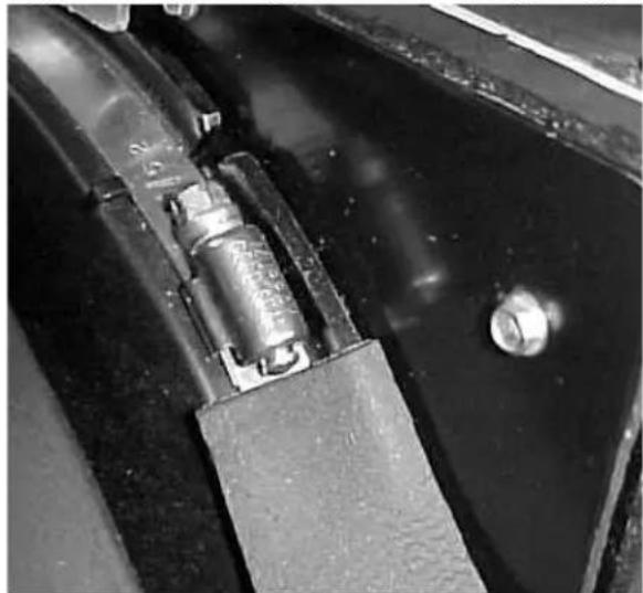
natural_image
Close-up of a mechanical component with a cylindrical spring and attached bracket (no visible text or symbols)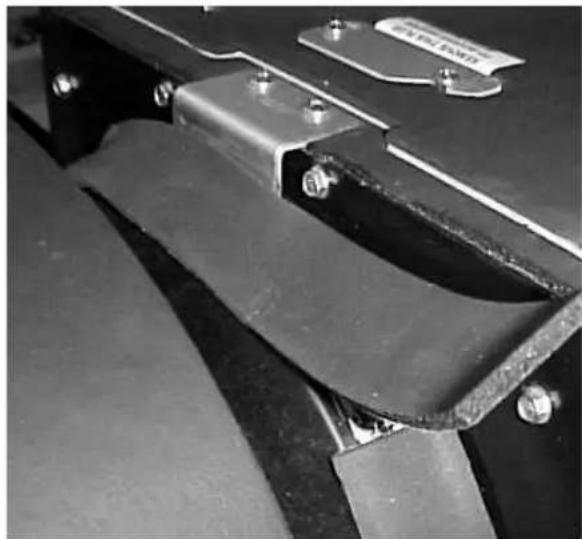
natural_image
Close-up of a metal bracket with bolts and a label, no readable text or symbols present.- Mounting: First insert the grommets. Then insert the sleeves. Use both clips in the front. Use both grommets and sleeves to secure the airhandler to the deck (see Figure 2). Also use two clips in the front to secure the airhandler to the deck. Thus, the airhandler is secured at four points (2 grommets + 2 clips). One clip goes anywhere on the left of the front drain, one clip goes on the right. Figure 3 shows the possible locations for the left clip.
Figure 2: Use grommets and sleeves when securing to deck
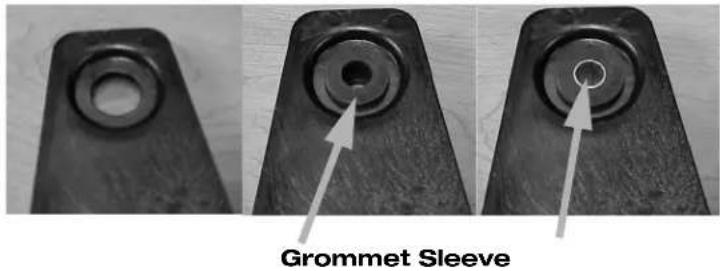
Figure 3: Circles mark the possible locations for left clip
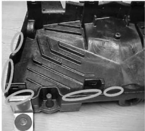
natural_image
Close-up of a mechanical component with multiple circular features and internal grooves (no visible text or symbols)- Drains: The two rear drains on AU airhandlers should always be installed. The front drain should be connected if needed for a particular application. Use only PVC hosebarbs with three wraps of threaded-seal tape. The front drain may be plugged using a PVC hosebarb with three wraps of threaded-seal tape.
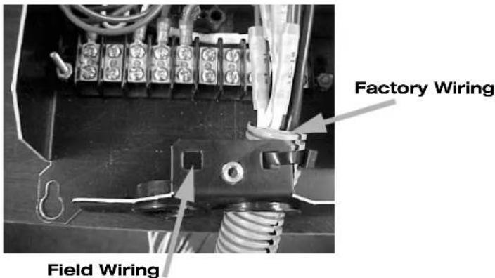
- Strain relief: Secure field wiring using a standard wire tie. The wire tie on the right secures the factory wiring, and there is provision on the left to secure the field wiring in the same manner as shown in Figure 4.
Figure 4: Securing the wiring
- Breathe Easy Option: Some AU airhandlers include a Breathe Easy™ air purifier. The Breathe Easy can also easily be added to AU airhandlers. This is highly recommended. The Breathe Easy is not a filter, nor is it a mere UV bulb. It is an air purification system consisting of a ultraviolet (UV) lamp and a photocatalytic oxidizer (PCO) nano-mesh. The lamp is of a wavelength that does NOT create destructive ozone. Many systems consist only of a UV bulb. Some of these create harmful ozone. And because they do not have a PCO, they are only able to affect living organisms. The Breathe Easy is able to reduce those same biological contaminants such as pollen, mold spores bacteria, viruses, but Breathe Easy is also able to reduce many other contaminants including fumes, smoke, odors, and VOCs.

WARNING
Ultraviolet (UV) light is harmful - never look directly at a lit UV lamp without UV protective glasses. Do not expose your skin directly to the UV light without protection. Note that the indirect light, the blue glow, is safe.
Turn off the breaker and then unplug the lamp before servicing. Remember that the bulb is glass and does get hot. Hot glass looks just like cold glass. Allow the lamp to cool for 5 minutes before servicing to avoid burns. The glass is fragile, so use safety gloves to avoid cuts if the glass should break. Replace the bulb annually. Models AU6-12 use bulb 4210800. Models AU18-24 use bulb 4210802.
- Overload Reset Access: There is a swivel plate on top of the unit that grants access to the reset button of the heater overload. Use a plastic pen or other non-conductive object to depress the overload button. Remember to cover the hole with the plate when finished. This helps prevent air from bypassing the coil.
FRESH AIR MAKE UP UNIT (FAMU)
The purpose of a FAMU is to pre-treat outside air before bringing it into the boat. This usually means removing humidity, and that is a FAMU's most important function. FAMUs are specially treated for extra corrosion resistance because they use outside air.
The way a FAMU pre-treats fresh air varies by temperature:
In warm weather - The FAMU uses cold water (if available) to cool the air. This removes moisture. To avoid over-cooling, the FAMU also has an electric heater to warm the air back up a little.
In cold weather - The FAMU uses hot water (if available) and/or electric heat to warm the air. In cold weather, moisture removal is not necessary.
FAMU - SPECIAL INSTALLATION REQUIREMENTS
FAMUs are installed like ordinary airhandlers, but have extra considerations:
- Locate the FAMU where the air will be as fresh and safe as possible. For example, do not locate it near exhausts or sources of carbon monoxide of any sort.
- Do not install in engine rooms.
- Do not expose to splashing water—use de-misting louvers if necessary.

WARNING
Do not install a FAMU near exhausts or sources of carbon monoxide of any sort.
Do not install in engine rooms.
FAMU - AVOID EXCESSIVE VELOCITY
In all cases, be careful of the air velocity across the coil. Excessive velocity can strip water droplets from the coil and entrain them in the air stream. This can result in mold, damaged blowers, wet ducts, etc. Excessive velocity can also result in inadequate dehumidification.
For a FAMU, do not exceed 250 feet-per-minute (76 meters-per-minute) across the coil. This is a general rule. Higher velocities may be permissible in drier climates. Determine the maximum coil velocity by temporarily removing the filter then use a vane anemometer to measure the air speed at all points across the face of the coil. The anemometer should be touching the coil. Readings even a short distance away are likely to be much lower. Reinstall the filter when done.
STANDARD MU CONTROL
Standard "MU" models include the standard MU control. The control comes wired to the unit—no additional control is needed.
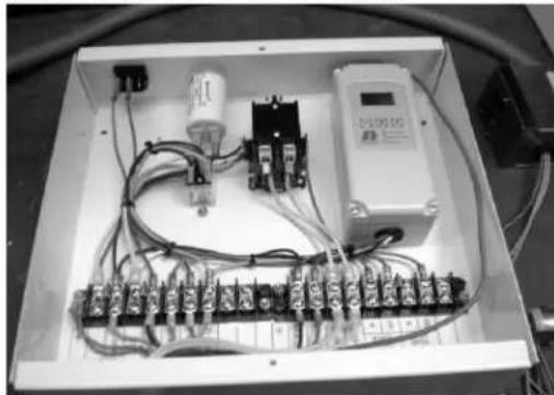
Figure 5: The Standard MU Control
natural_image
Interior view of an electronic control panel with visible wiring and circuit board (no text or symbols)STANDARD MU CONTROL - SETUP
Per the wiring diagram included with the unit, note that the transformer wiring must be reconfigured for 208VAC applications. It is factory wired for 230VAC.
Units with DC blowers include a knob for adjusting the blower speed. Refer to the "FAMU - Avoid Excessive Velocity" section. The thermostat is factory set at 70°F (21.1°C). There is usually no reason to change it. There is also a fuse and an on/off switch.
A standard MU control includes an air temperature sensor in the discharge of the FAMU. It also includes a Change Over Switch (COS). The COS indicates if the water in the pipe is hot or cold.
- If the water in the pipe is cold, then the valve opens. The cold water cools and dehumidifies the air.
a. If the discharge air is colder than setpoint, then the heater is pulsed on to warm the air. b. If the discharge air is warmer than setpoint, then the heater stays off.
- If the water in the pipe is hot, then the valve pulses with the heater.
a. If the discharge air is colder than setpoint, then the heater and the valve are pulsed on to warm the air. b. If the discharge air is warmer than setpoint, then the heater and the valve stay off.
SMU CONTROL
The SMU control is also known as the "steady heat" MU control. These units have "SMU" in the model number. The control comes wired to the unit—no additional control is needed. The SMU control benefits the generator by reducing electric heater cycles. Instead of frequently pulsing a larger heater on and off, the SMU leaves a smaller electric heater on or off for a long period because it's based on the temperature of the inlet air.
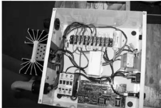
Figure 6: The SMU Control
natural_image
Interior view of an electrical control box with wiring and terminal blocks (no visible text or symbols)SMU CONTROL - SETUP
Units with DC blowers include a knob for adjusting the blower speed. Refer to the "FAMU - Avoid Excessive Velocity" section.
Most SMU units are intended for use with remote, field-wired switches. One switch controls the blower. One switch enables the heater. The heater will not run if the blower is off.
The SMU control has a two-stage thermostat and two setpoints - S1 and S2. Both are field adjustable, but should not usually be changed. S1 is factory set to 60°F (15.6°C). S2 is factory set to 50°F (10°C).
- If the outside air temperature is warmer than S1 and S2:
a. If the water in the pipe is cold, then the valve and the electric heater turn on.
b. If the water in the pipe is hot, then the valve and the electric heater turn off.
-
If the outside air temperature is between S1 and S2, then the valve and electric heater turn off.
-
If the outside air temperature is colder than S1 and S2, then the electric heater turns off and:
a. If the water in the pipe is cold, then the valve turns off.
b. If the water in the pipe is hot, then the valve turns on.
CIRCULATING WATER SYSTEM
SERVICE VALVES
Ball valves are required before and after each airhandler (see Figure 7). Always use full-flow ball valves. The ball valve for an airhandler should be 34 " full port for all airhandlers up to 24K. Airhandlers 30-36K should be 1" full port.
Figure 7: Diagram of Airhandler Piping and Service Valves
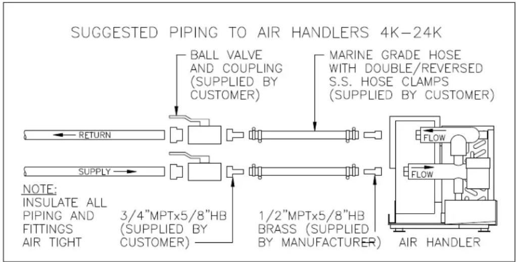
flowchart
graph TD
    A["SUGGESTED PIPING TO AIR HANDLERS 4K-24K"] --> B["BALL VALVE AND COUPLING (SUPPLIED BY CUSTOMER)"]
    A --> C["MARINE GRADE HOSE WITH DOUBLE/REversed S.S. HOSE CLAMPS (SUPPLIED BY CUSTOMER)"]
    B --> D["RETURN"]
    C --> E["SUPPLY"]
    D --> F["INSULATE ALL PIPING AND FITTINGS AIR TIGHT"]
    E --> G["3/4"MPTx5/8"HB (SUPPLIED BY CUSTOMER)"]
    E --> H["1/2"MPTx5/8"HB BRASS (SUPPLIED BY MANUFACTURER)"]
    H --> I["AIR HANDLER"]
HOSE
Flexible, reinforced hose between the service valve and the unit will isolate vibration. Hose to an airhandler should match the hosebarb that comes with the airhandler. Each hose connection should use double/reversed stainless steel hose clamps.
WATER FLOW DIRECTION
Note the arrows on the unit indicating direction of water flow. Reversing the flow can cause a number of problems, such as reduced performance and air lock. In general, the water usually enters low and exits high.
TIGHT CONNECTIONS
Always be sure to double-check connections (especially hose clamps) for correct placement and tightness. If possible, double hose clamps should be used at every hose connection for redundant protection against leaks. The hose clamp screws should be located opposite one another.
AIR BLEEDERS
Provision must be made to remove air from the system. All airhandlers include bleeder valves. Note that when air is bled from the system, water will usually be released also. The water may be collected in a sump or a bucket. Plan ahead to avoid a mess.
STRAINER
Strainers are mandatory in the condenser/seawater circuit AND in the circulated water circuit. Failure to follow these guidelines will void the warranty!
The circulated water strainer should be a 20-mesh "Y-strainer". Finer meshes will clean the system better, but they are likely to need cleaning too often and thus become a nuisance. More open meshes must not be used because they will not adequately protect the components.
CLEANLINESS
- Clean Coils: Boat yards are often very dusty places, especially while a boat is being built. This dust can quickly clog an airhandler coil if precautions are not taken. The safest thing to do is to put a piece of cardboard in front of the coil for protection, and do not operate the airhandler until the boat is finished. However, it is usually necessary to run the airhandlers during construction. If so, use a good quality, disposable filter. This will keep the coils looking new. Be sure to remove and replace those filters as needed and before delivery of the boat to the customer.
- Clean Water: Be sure the water going to the airhandlers is clean. When the boat is first constructed, or if much piping is changed, the circulated water system should be thoroughly flushed. Short-circuit the airhandler's service ball valves so that no water flows through the airhandler during this process. And, include a 20-mesh strainer. The chiller manual describes these requirements in more detail.
THERMAL INSULATION
- When to insulate: Leak checking the system after everything is insulated is sure to create frustration. Before the leak check, it is OK to insulate straight lengths of pipe, but do not insulate the joints or fittings until AFTER the leak check. If there are any leaks, they will probably be at the joints or fittings. Having the joints and fittings still uninsulated will make the leaks easier to find and fix. After checking for leaks, insulate the joints and fittings. Any exposed pipe can sweat and cause water damage so it is very important to insulate the piping thoroughly.
- Insulation material: We recommend closed cell insulation at least 3/4" thick insulation on the pipes. Piping through unconditioned space or other areas where the dewpoint may exceed 74°F will require thicker insulation.
- Size: The internal diameter of the insulation should match the external diameter of the pipe. If the insulation is too large, air will get between the insulation and the pipe and create condensation that may run down the pipe and show up some place else. This condensation will be minimal if the air cannot circulate, but it is better to avoid it altogether by avoiding the air gap. If the insulation is too small, it will be difficult to install. If split insulation is too small, it may eventually split open. Taping the split insulation all around will prevent this. The ideal solution is un-split insulation that closely fits or is just a little snug.
- Thorough: All piping should be thoroughly insulated to prevent condensation. Improper insulation is a common problem with chilled water systems, and very difficult to find and correct, even after the water damage is noticed. A gap in the insulation will produce condensation on the pipes, which can run down inside the insulation to a different location. Insulation must be air tight.
- Split insulation: If using split insulation, seams should be closed tightly, sealed with glue or tape. Completely wrapping split insulation with a sturdy cloth tape will also make it more durable and much less likely to split back open. All water fittings, connections, valves, etc. in the system should be well insulated, after the system is leak tested.
- Do not compress: Do not compress the insulation. For example, do not use tie wraps on insulation. The localized compression will cause poor performance, condensation, and eventually damage the insulation.
FLOW CONTROLS
Dometic offers and recommends a flow control on each airhandler. If some airhandlers take more water flow than they are designed for, that means other airhandlers will likely get less water flow than they need. Flow controls help ensure that no airhandler takes more flow than it should, and thus all the airhandlers get what they need. (The chillers do not need flow controls.)
CONDENSATE WATER

WARNING
Do not terminate condensate drain lines within four (4) feet of any outlet of engine or generator exhaust fumes, nor in a compartment housing an engine or generator, nor in a bilge, nor anywhere else containing hazardous fumes, unless the drain is connected properly to a sealed condensate or shower sump pump. Otherwise, those fumes may travel up the condensate line and contaminate living spaces.
ROUTING
Connect the condensate outlets to proper tubing and route to an appropriate location such as an overboard fitting or sump. Do not permit condensate to puddle in the bilge. Be sure the condensate line follows a consistently downhill route free of loops, kinks, or upward bends. When considered necessary, P-traps could be used to stop undesired vapors from traveling up the condensate line. Avoid creating any unintentional air traps which could prevent proper drainage.
TEE FITTINGS
Most airhandlers have at least two condensate drains. These may be connected together into a single drain line using a tee if a minimum 2" (5.1cm) drop exists from the drains to the tee.
HEEL PROTECTION
For installations on sailboats or any vessel that heels more than 15°, position airhandlers so that the condensate pans drain port and starboard. Note that most airhandlers have two or more drain connections. One drain connection should be on the port side, the other should be starboard.
CONNECTION
Attach a 5/8" id reinforced hose to the connection provided and tighten with a single hose clamp
THERMAL INSULATION
Because the condensate water is cold, it will make the condensate plumbing cold, too. Thus, water can condense on the outside of the condensate plumbing if it is not insulated. This is called "secondary condensation". This is why Dometic always insulates condensate drain pans.
In many applications, the condensate lines do not get cold enough and the ambient air is dry enough that little or no condensate occurs even on uninsulated condensate plumbing. However, we recommend 3/8" wall closed cell insulation on the condensate plumbing as a precaution, especially if it must pass through unconditioned spaces.
TEST
Test the condensate routing by pouring a quart of water into the pan and checking for flow.
ELECTRICAL
WIRING DIAGRAM
Connect power and accessories per the wiring diagram that came with the unit. The diagram will normally be found in the electric box. If you are installing a Gold Series airhandler with the EU Package, see below.
GOLD SERIES (AU) WITH THE EU PACKAGE
The EU Package includes plugs instead of junction boxes. This makes installation quicker and easier. It eliminates the possibility of most wiring errors. It also makes it easy to disconnect an individual airhandler from power.
Before the plugs will attach, two things must happen. First, the slots on the male plug must align with the keys on the female plug. The DC plugs are shown below; the HV plugs are the same, only with fewer pins. See Figure 8.
Figure 8: Male and female plugs of EU Package (DC shown)
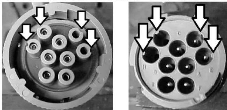
natural_image
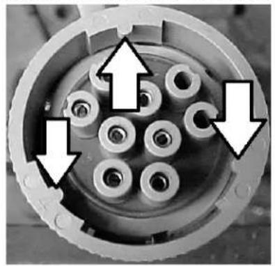
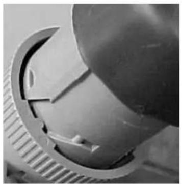
Close-up of two views of a mechanical component with multiple cylindrical pins and mounting holes, showing internal structure and mounting arrows (no text or symbols)Second, the male plug has a ring around it with a key. The key must be aligned with the slots on the female plug as shown in Figure 9, then twist the ring to lock it in place as shown in Figure 10.
Figure 9: Align key with slots
natural_image
Close-up of a mechanical component with multiple cylindrical holes and directional arrows indicating movement (no text or symbols)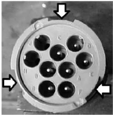
natural_image
Close-up of a circular mechanical component with multiple black holes and labeled points (no readable text or symbols)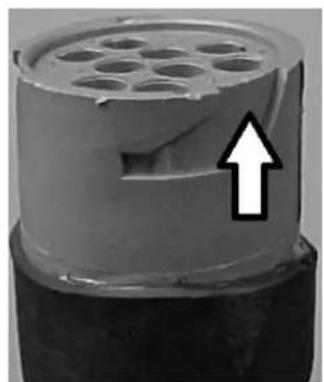
natural_image
Close-up of a cylindrical mechanical component with hexagonal holes and a black arrow pointing upward (no text or symbols)Figure 10: Align and twist
natural_image
Close-up of a metallic mechanical component with curved and grooved surfaces (no visible text or symbols)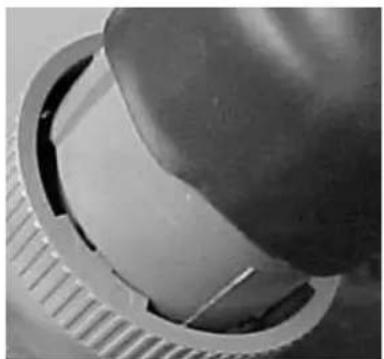
natural_image
Close-up of a mechanical component with a circular housing and textured surface (no visible text or symbols)MAX FUSE - CIRCUIT BREAKERS
"Max fuse" is indicated on the unit's label. It is the maximum allowable size for the HACR breaker or fuse. Smaller sizes are allowable and may be desirable. However, sizing the breaker too small invites nuisance trips. Breakers are usually sized at 175% to 200% of the current load. Curve 10 breakers should be used for the chillers due to the starting loads of the compressors. Always check with regulation codes (ABYC or Coast Guard) for final sizing of breakers or wiring.
MCA - MINIMUM CIRCUIT AMPACITY
MCA is indicated on the unit's label. Your wiring must be designed to continuously carry this electrical current. Be sure to read ABYC concerning wire type, size, ambient conditions, etc.
ELECTRICAL GROUNDING

WARNING
Failure to properly ground the unit can result in injury or death.
All units must be effectively grounded to minimize the hazard of electric shock and personal injury. This should be done by connecting a ground wire to the ground inside the electric box. Custom units, such as those lacking an electric box, may require other methods of grounding. Ground any given unit as indicated by the wiring diagram that comes with it. AC (alternating current) grounding (green wire) must be provided with the AC power conductors and connected to the ground terminal (marked "GRND") at the AC power input terminal block of the unit(s), per ABYC standard E-8, or equivalent.
CONTROLS
Dometic offers a variety of control solutions. The limited wiring information provided in this manual is applicable regardless of what style controls are used. Your controls manual has more information specific to the particular type of controls used on your system. Be sure to read it carefully.
MOUNTING THE DISPLAY
- The display must be put somewhere that it can measure the average room temperature. Mount the display mid-height of the cabin on an inside wall where it can measure freely circulating air. Never mount a display in direct sunlight or in the supply-air stream.
• If the display is mounted using its adhesive strips, the mounting surface must be smooth and clean. - If using screws, do not use a screw gun, and do not over-tighten the screws.
WATER SENSORS
The main function of the water sensor is to report the temperature of the water entering the airhandler to the control. It is therefore essential that the sensor make good thermal contact with the copper. For example, if the control wants cooling but the sensor is reporting the hot ambient rather than the cold copper temperature, then the control will think the water is hot. If the control wants cooling but thinks the water is hot, the control will not open the valve.
Water sensors should normally be attached to the copper tube where the circulating water enters the airhandler. Be sure it is making good thermal contact with the copper. Never attach a sensor to plastic pipe or hose.
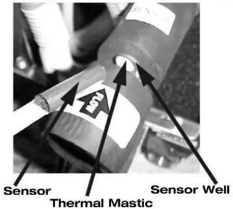
Many airhandlers have a sensor well for this purpose. The sensor should be put in the sensor well. Be sure there is plenty of thermal mastic to ensure good thermal contact and hold it in position with electrical tape. See Figure 11.
Figure 11: Securing the sensor to the sensor well
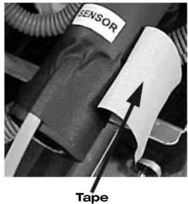
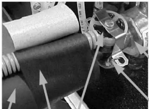
If there is no sensor well, use a little thermal mastic and tighten the sensor to the copper. A band clamp works well for this purpose. This is also a good way to secure the sensor. Just don't tighten it so much that you crush the copper. Do not use tape to hold the sensor to the copper, because condensation will cause it to loosen over time. See Figure 12.
Figure 12: Securing the sensor to the copper
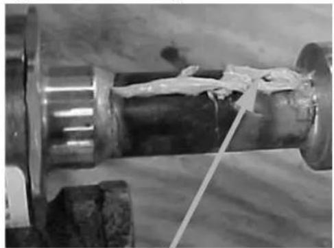
natural_image
Close-up of a mechanical component with a wire and wet material, no visible text or symbols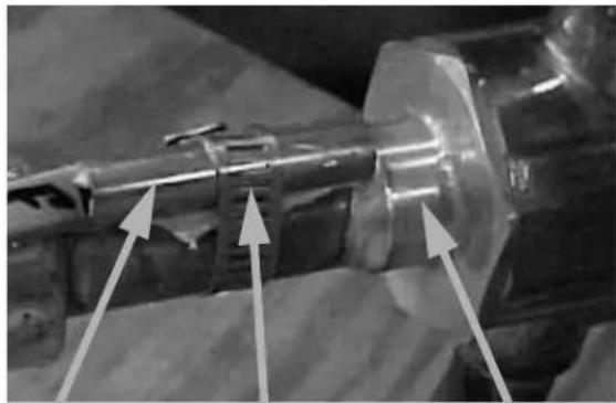
natural_image
Close-up of a mechanical component with three directional arrows pointing to features (no visible text or symbols)Thermal Mastic Sensor Band Clamp 3-Way Valve
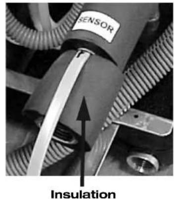
Regardless whether or not there is a sensor well, secure the sensor so it cannot be accidentally dislodged. As always, do not compress the insulation. Insulate the pipe and sensor together, so that the sensor reads the copper temperature and not the ambient air.
For the Gold Series airhandler with the EU Package the sensor well is in a slightly different location, as shown. In this position, the water sensor does not require insulation. The water sensor should be secured with a tie-wrap.
Figure 13: Water sensor location for Gold Series EU Package
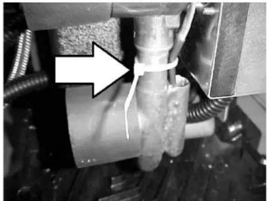
natural_image
Close-up of a mechanical assembly with hoses and a pipe fitting, no visible text or symbolsSome units use a "change-over-switch" (COS). These are commonly found on Fresh Air Makeup Units (FAMUs). They are held on with a spring. Note that the spring may NOT be adequate to secure the wire. Because they are switches rather than sensors, it is not usually necessary to insulate them.
Figure 14: Securing the sensor to a COS
natural_image
Close-up of mechanical components with directional arrows indicating movement or force (no visible text or symbols)3-Way Valve
Insulation Tape COS Spring
AIR SENSORS
Outside air sensor: If an outside air sensor is used, do not mount it in direct sunlight or on a hot surface.
Built-in display sensor: Cruisair displays do not have a built-in sensor. But, most Marine Air displays have a built-in sensor for measuring the room temperature. In cases where the display has a sensor, the following rules for sensors apply to the display also, unless a remote return-air sensor is used.
Sensor location: NEVER put a sensor in direct sunlight, near any heat producing appliances, on an outside wall, or in a bulkhead where heat from behind the panel might affect the sensor. NEVER put a sensor in a location where supply air can blow directly on it. NEVER put a sensor near or directly under a diffuser. NEVER put a sensor behind a door, in a corner, under a stairwell, or any place where the air is not freely circulating. Do not put them in cabinets.
Remote return-air sensors: Most applications do not need a separate return-air sensor, because the sensor in the display provides excellent control. If a return-air sensor is used, put it in a location where it will read the temperature of the return air. If a remote sensor is used, the sensor in the display is ignored. Return-air sensors should only be used if the display must be mounted in a location that violates one of the above rules for sensor location.
Air sensor location for Gold Series with EU Package: The air sensor should be installed as shown in Figure 15:
Figure 15: Placement of air sensor for Gold Series with EU Package
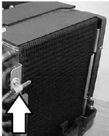
natural_image
Close-up of a black mechanical component with a white arrow pointing to a feature, no visible text or symbols.START-UP
PRESSURE PORTS
Some airhandlers have 14 " Shrader valves as pressure ports. With the valve in the "open" position, use the pressure ports to make sure water is flowing through the airhandler in the right direction. High pressure corresponds to the water inlet. Low pressure is the water out.
The gauge you use to measure water pressure must NOT be used to measure refrigerant pressures! Otherwise, you will contaminate the refrigerant circuit with moisture.
BLEEDING
- For new installations, follow the procedures in the chiller manual.
- When retrofitting a new airhandler, open only the inlet valve. Bleed as much air as possible. After bleeding the air, open the return valve (water out of the airhandler).
- Add water and anti-freeze as necessary to maintain the correct system pressure and freeze protection as indicated in the chiller manual.
- Note: Low water pressure can cause some airhandlers, especially those high up, to be put into a negative pressure situation. Whenever an airhandler's bleeder valve is opened, water should come out in a pressurized stream. If air comes OUT, it means the system has not been completely bled. If NOTHING comes out, it probably means there is not enough water pressure in the system.
FINAL AIRHANDLER INSPECTION
The following checklist is only for the airhandlers:
PLUMBING
- Are the water connections double/reversed hose clamped, with the screw-heads on opposite sides?
- Are the service valves open?
• Is the bleeder valve closed.
• Is the lever on the 3-way valve in the proper position? - Are the units mounted secure and level?
• Are condensate drains properly routed to an overboard discharge or sump? - Have any unused drain holes in the condensate pan been plugged?
• Do the condensate line consistently run downhill, with the drain pan as the highest point? - Has the condensate line been tested with a quart of water poured into the drain pan?
- Are the condensate lines insulated?
-
Are the inlet and outlet pipes connected properly?
-
Are joints and tees properly insulated?
- Are pipes individually insulated?
- Are pipes fastened securely to the boat as needed throughout their length?
- Does the system have the proper amount of antifreeze? Have you tested it with a refractometer?
AIR DISTRIBUTION SYSTEM
- Is there unobstructed airflow from the return-air grille to the coil?
• Is there a lint screen or filter in the return-air path where it is accessible for regular cleaning? - Have flexible ducts been pulled tight to remove bends and constrictions?
- Are grills and ducts correctly sized for the system?
• Have all gaps been plugged to prevent air from bypassing the return-air grille's filter?
CONTROLS AND WIRING
- Is the return-air sensor properly located and secured in the return-air path, out of direct sunlight, and out of direct contact with any metal objects?
- Are all wiring harnesses properly secured?
- Are wiring connections made, color to color, correctly at terminal strips?
- Are plugs and pins properly aligned and securely connected?
- Are all components properly grounded?
- Are the breakers and wire of the correct size and type?
- Are terminal strips located in a dry, safe place and properly covered?
OPERATION
If you want to turn off power to an airhandler while the airhandler's electric heater is still hot or running, residual heat may cause the manual thermal overload to trip. If that happens, you will not be able to operate the electric heater again until the overload has been manually reset. To avoid this, turn the heater off while allowing the blower to continue to run at high speed for 3 minutes. This will cool the heater off and prevent the overload from tripping.
AVOIDING FROZEN AIRHANDLERS
One of the advantages of chilled water is that dirty filters and reduced air flow cannot cause frozen coils. However, sub-freezing air temperatures CAN cause chilled water airhandlers to freeze if the ambient or inlet air is cold enough.
Anti-freeze in the system will protect the airhandlers AND the chillers to a point. We recommend a 20% by volume propylene glycol solution. Do not greatly exceed 20% propylene glycol, because performance will suffer. In any case, never allow the freezing point to rise above 20^ F. Thus, the unit can never freeze unless the ambient air temperature is below 20^ F. Use a digital refractometer to check the concentration of the antifreeze. Always use a non-toxic antifreeze.
Water flowing through the unit tends to protect against freezing. Hot flowing water gives more protection. But, if a service valve is closed, or if the 3-way valve is in the bypass position for any reason, the water in the coil will eventually reach the same temperature as the ambient air. If the ambient air temperature is below the freezing point of the water, the water will freeze and the coil will rupture.
With cold outside air, most fresh air makeup units will keep the valve open if the water is hot. But if the water is not hot, or if the sensor is cold, then the control will close the valve. Also, anything that kills power to the control or valve will cause the valve to close. If in doubt about the 3-way valve, the safest thing is to lock the lever in the "open" position. This will allow water to continue flowing through the coil.
CONTROLS
Dometic supplies a variety of controls for airhandlers and chillers. Refer to the appropriate control manual for more information.
AIRHANDLER MAINTENANCE
MONTHLY
AIR FILTERS
Dirty filters will reduce airflow and capacity. At least once a month, check the lint screen or filter behind the return-air grille or on the face of the airhandler. Replace or clean if necessary. The pleated, Breath Easy ^TM microparticle filters should be replaced, not cleaned. Reusable plastic filters should be vacuumed or washed with tap water. Do not use soap or solvents.
RUN THE SYSTEM
It is recommended that systems be operated regularly. Vessels not in use should have their chillers and airhandlers cycled on 30-60 minutes once a month. Vessels in use should cycle on limited-use components in similar intervals to those above. Systems should also be cycled to their reverse mode (cool to heat, heat to cool). This helps to maintain pump seals and internal mechanical contacts, while reducing the fouling effect of marine growth in the seawater circuit.
EVERY THREE MONTHS
CONDENSATE DRAINS
Check the airhandler and chiller condensate drains for obstructions by pouring a quart of water rapidly into the condensate pan. If it does not drain completely within 30 seconds, check the drain outlets for clogging. Remember that many Dometic systems have two drains, one at each end of the unit.
YEARLY
FREEZE PROTECTION
Check the level of non-toxic anti-freeze protection using a refractometer. 20% propylene glycol is recommended. Never allow the freezing point to rise above 20^ F.
AIRHANDLER VALVES
Airhandler motorized water valves should be inspected for corrosion that may bind the gear.
- With the airhandler off, access the water valve and remove the motor case. Inspect the gears and remove any build-up on the motor gear and/or the valve gear.
- Dry thoroughly and lubricate with a silicon spray or equivalent.
- Manually test the gear mechanism using the lever on the top of the valve before reassembly.
SENSORS
All control probes and sensors should be inspected for proper location and fastening. Improperly located and/or secured probes will provide erroneous readings, causing improper operation.
- Check all sensors at each airhandler for proper location. Water sensors should be securely fastened and insulated on the supply connection (water inlet) of the airhandler.
- If the built in air sensor on the controller display panel is not utilized, the remote air sensors should be located in the return-air stream as close to the cabin area as possible without being in contact with any other hot or cold surface.
- Sensors in loose-fitting sensor wells require generous thermal compound. Thermal compound is designed to readily transfer heat, and thus it helps the sensor maintain good thermal contact. The sensor well should be insulated.
- All sensors externally fastened to coils, pipes, etc. should be securely fastened with thermal mastic between the contact surfaces and insulated when necessary to provide accurate readings.
TROUBLESHOOTING

CAUTION
Do not leave any safeties (i.e., flowswitch, high pressure switch, low pressure switch, freeze sensor) switched/jumped out. They are safety devices designed to protect the system. Damage to the chillers could result if the safety devices are not working.

CAUTION
If a safety trips, it is important to find out WHY it tripped and fix the root problem. For example, a chiller may be able to adequately cool a boat despite the fact that the flow switch trips intermittently. But if a flow problem goes uncorrected, it will likely cause the evaporator to freeze and rupture. This is considered negligence and is NOT covered under warranty. DO NOT IGNORE THE SAFETIES! Find and fix the root cause.
BLOWER NOT RUNNING
- Check the circuit breaker. Turn it completely off, then back on.
- If it trips again immediately, then do NOT turn the breaker back on—there is likely a dangerous short-circuit. Call a trained technician to locate and fix the short-circuit.
- Read the control manual. Are you sure the blower SHOULD be running?
- If there is voltage at the blower but it is not running, then the blower motor or capacitor (if any) is bad.
BLOWER RUNNING, BUT NOT COOLING/HEATING
-
Check the position of the lever on the 3-way valve. If it moves to the "open"/energized position without resistance, then it is open. When the valve is energized, the lever can be easily moved to either position, but the valve remains open. If it moves to the open position but the spring resists the movement, then the valve is closed. When the valve is de-energized, the spring will try to move the lever back to the closed position.
• The 3-way valve is closed: -
Is there correct voltage at the valve? If there is correct voltage at the valve, it should be open unless the actuator is bad or improperly connected to the valve.
- Is the water in the pipe cold/hot? In cool mode, the valve will not open if the sensor cannot detect cold water. In cool mode, the water in the pipe should typically be 44 - 46^ . In heat mode, the water in the pipe should typically be 110 - 120^ .
- Is the water sensor or change-over-switch insulated and making good contact with the copper pipe? In cool mode, the valve will not open if the sensor cannot detect cold water. In heat mode, the valve will not open if the sensor cannot detect hot water.
- Read the control manual. SHOULD the valve be open?
- The 3-way valve is open: Check the airflow. If the TD (temperature difference between entering and exiting air) at full speed is greater than 18^ , then airflow may be low. NOTE: Poor airflow tends to cause the TD to increase, but the total cooling/heating effect is reduced due to the loss of air flow. Also note, 18^ is a rule of thumb, but TD can vary depending on airflow, air temperature, water flow, and water temperature.
- Airflow is low:
- Dirty filter - at the return-air grille or on the unit
• D i r t y c o i l - Blower is at low speed
- Low voltage (more than 10% below the rated voltage) to the blower. Note: Many controls adjust blower voltage to adjust the airflow. Multi-meters often have difficulty reading the "chopped" voltage accurately. Read your control manual for details on fan speed control.
- Restriction in the ductwork
- Wrong or faulty capacitor
• Water flow is inadequate.
- Is the coil air-locked? Try opening the airhandler's bleed valve for a few seconds. Water should come out in a steady, pressurized stream. If the airhandler has to be bled regularly, the system may have inadequate pressure, leaks, or both.
- A gurgling sound indicates air in the system. Bleed the airhandler and the entire system. Fix any leaks, add water, and raise the water pressure as appropriate.
-
Make sure the airhandler's service ball valves are open.
-
Dirty circulating water strainer.
- Pump problem, possibly a worn impeller.
• Has the water system changed? For example, another airhandler has been added or a flow control removed.
- The heat load may be exceeding design. Look out for external loads such as open doors and windows. Look out for internal loads such as showers, ovens, high-wattage electronics/lights - especially if they have recently been added or have increased usage.
Noisy Airhandler
• Any foreign object inside the blower can create loud noise and possibly damage the blower.
- Shipping or handling damage may cause the spinning blower wheel to rub on the blower inlet.
- A gurgling sound indicates air in system. Bleed the airhandler and the entire system. Fix any leaks, add water, and raise the water pressure as appropriate.
• Air noise may be caused from duct problems or a bad blower. Read the section on Audible Noise.
- A clicking sound with airhandler fan off, but circulation pump running, may be a bad flow control valve, or even a circulation pump problem.
GLOSSARY
3-WAY VALVE: . An electrically operated water regulating valve on an individual airhandler controlled by the thermostat. This valve provides water flow through the airhandler when opened, and bypasses water flow from the supply side to the return side when closed. On airhandlers, 3-way valves are superior to modulating valves because they provide better humidity control. The voltage supplied to the 3-way valve should be ±10% of its nominal rating.
AIRHANDLER: The fan coil unit that circulates air into a specific area for heating or cooling.
BLEEDER PORTS: Capped ports connected to 1/4" flexible tubing located on the airhandlers for purging air from the chilled water circulation system.
BTU: (British Thermal Unit) A common term used to define and measure capacity or refrigeration effect.
CFM: Abbreviation for "cubic feet per minute", a term used to specify the volume of airflow through the airhandlers and ducting.
CHILL CHASER: An auxiliary electric heater located in the airhandler.
CIRCUIT BREAKER: An electrical device which provides high current and short circuit protection for the compressor, airhandlers and pumps used in the chilled water system. HACR (heating, air conditioning & refrigeration) type circuit breakers are recommended for the ship's panel. HACR circuit breakers have a long delay to compensate for the electrical surge associated with compressor.
CONDENSATE DRAIN PAN: The pan directly under the airhandler's coil for removal of the "condensed" moisture taken out of the cabin air. Two drain spud attachments are provided for connection to drain hoses for proper removal of the water to a sump. There is also a condensate drain pan located under each chiller and the chilled water pump.
ELECTRIC HEAT: Electric resistance heaters are used as a chill chaser in the air handlers to warm the air, or in the chiller heater barrels to warm the circulating water in heat mode.
FILL ASSEMBLY: The point where a water hose is temporarily attached to the circulating water circuit in order to fill it. The fill assembly typically includes a ball valve and a pressure reducing valve.
GPM: Abbreviation for "gallons per minute", a term used to specify the amount of water flow through the chilled water or seawater system.
R-VALUE: R-value is the industry standard measure of a material's resistance to heat transfer. The higher the R-value, the more effective it is as an insulator.
RUN CAPACITOR: An electrical storage device used to reduce amperage to some electric motors for more efficient operation.
SEMICONDITIONED SPACE: A semiconditioned space is a space that meets the following requirements:
- It is at least 95% bounded by conditioned spaces, or by other semiconditioned spaces, or by vertical surfaces with at least R4 insulation.
- It is not exposed to outside air. There must be an effective vapor barrier.
- It is exposed to conditioned, return air.
- It is not conditioned with its own diffusers.
One example is the horizontal crawl space that divides two conditioned decks. Another example is the vertical space between a salon and the wall that separates it from the outdoors. In such a case, the wall should be insulated with at least R4 insulation.
SPIROTOP® is a registered trademark of Spirotherm, Inc. It is a device used to remove air from circulating water. It is typically installed at high points in the system.
SPIROVENT ^® is a registered trademark of Spirotherm, Inc. It is a device used to remove air from circulating water. It is typically installed inline in the circulating water piping in the engine room upstream of the pump.
THERMOSTAT: An adjustable control device that senses room temperature, via an air thermistor or sensor, and operates the motorized valve (if installed) on an airhandler for water flow. For example, it is necessary in most sensor wells.
TON: In refrigeration/air conditioning, a ton is the amount of heat absorbed in melting a ton (2000 pounds/908 kg) of ice over a 24-hour period. The ton of refrigeration is equal to 288,000 BTU in 24 hours. Divide 288,000 by 24 and get 12,000 BTU per hour. Therefore, one ton of refrigeration = 12,000 BTU/hr.
VAPOR BARRIER: A thin layer of material that prevents vapor from entering the protected space. Insulation without a vapor barrier, with a compromised vapor barrier, or with the vapor barrier in the wrong place will allow water vapor to migrate through the insulation and condense on the cold surface. The insulation must be between the cold surface and the vapor barrier.
Y STRAINER: A serviceable inline device used to filter debris from the water. It has a physical shape reminiscent of the letter "Y".
NOTES
NOTES
DOMETIC MARINE DIVISION
2000 N. Andrews Ave.
Pompano Beach, FL 33069 USA
Tel +1 954-973-2477
Fax +1 954-979-4414
Email MarineSales@dometic.com
24/7 TECH SUPPORT FOR UNITED STATES AND CANADA
8:00 AM to 5:00 PM Eastern Time: +1 800-542-2477
After hours and weekends: +1 888-440-4494
INTERNATIONAL SALES AND SERVICE
Europe and the Middle East: +44 (0) 870-330-6101
For all other areas visit our website to find your nearest distributor.
dometic.com

- Installation, Operation & Maintenance Manual
- Table of Contents
- INTRODUCTION 1
- SAFETY 1
- HOW IT WORKS 2
- APPLICATION & INSTALLATION STANDARDS 2
- INSTALLATION....2
- AIR DISTRIBUTION 4
- ELECTRIC HEAT 7
- SPECIFIC MODELS 7
- FRESH AIR MAKE UP UNIT (FAMU) 10
- CIRCULATING WATER SYSTEM 12
- CONDENSATE WATER 13
- ELECTRICAL 14
- START-UP 18
- OPERATION 19
- TROUBLESHOOTING 21
- GLOSSARY 23
- INTRODUCTION
- SAFETY
- RECOGNIZE SAFETY SYMBOLS, WORDS AND LABELS
- WARNING
- CAUTION
- OPERATIONAL SAFETY
- HOW IT WORKS
- APPLICATION & INSTALLATION STANDARDS
- MOUNTING
- LOCATION OF AIRHANDLERS
- SAFETY FIRST!
- SOLID AND LEVEL
- ACCESS
- AUDIBLE NOISE
- AVOID CONDENSATION
- FREEZE PROTECTION
- MINIMIZING AUDIBLE NOISE
- KEY PRINCIPLES
- PRACTICAL SUGGESTIONS
- AIR DISTRIBUTION
- THERMAL INSULATION
- ATTACHING FLEX DUCT TO MOUNT RING
- OVAL DUCT RINGS
- DUCT INSTALLATION
- SIZING OF DUCTS, GRILLES, AND PLENUMS
- FREE AREA
- CALCULATING AREA
- TRANSITION BOXES
- PLENUMS
- DUAL BLOWERS
- RETURN-AIR DUCT
- SLIMLINES
- BLOWTHROUGHS
- SUPPLY-AIR GRILLES
- RETURN-AIR GRILLES
- EXCESSIVE AIR VELOCITY
- ELECTRIC HEAT
- SPECIFIC MODELS
- AT AIRHANDLERS
- ATL AIRHANDLERS
- ATV AIRHANDLERS
- ABL AIRHANDLERS
- BLOWTHROUGH AIRHANDLERS
- GOLD SERIES (AU) AIRHANDLERS
- FRESH AIR MAKE UP UNIT (FAMU)
- FAMU - SPECIAL INSTALLATION REQUIREMENTS
- FAMU - AVOID EXCESSIVE VELOCITY
- STANDARD MU CONTROL
- STANDARD MU CONTROL - SETUP
- SMU CONTROL
- SMU CONTROL - SETUP
- CIRCULATING WATER SYSTEM
- SERVICE VALVES
- HOSE
- WATER FLOW DIRECTION
- TIGHT CONNECTIONS
- AIR BLEEDERS
- STRAINER
- CLEANLINESS
- FLOW CONTROLS
- CONDENSATE WATER
- ROUTING
- TEE FITTINGS
- HEEL PROTECTION
- CONNECTION
- TEST
- ELECTRICAL
- WIRING DIAGRAM
- GOLD SERIES (AU) WITH THE EU PACKAGE
- MAX FUSE - CIRCUIT BREAKERS
- MCA - MINIMUM CIRCUIT AMPACITY
- ELECTRICAL GROUNDING
- CONTROLS
- MOUNTING THE DISPLAY
- WATER SENSORS
- AIR SENSORS
- START-UP
- PRESSURE PORTS
- BLEEDING
- FINAL AIRHANDLER INSPECTION
- PLUMBING
- AIR DISTRIBUTION SYSTEM
- CONTROLS AND WIRING
- OPERATION
- AVOIDING FROZEN AIRHANDLERS
- AIRHANDLER MAINTENANCE
- MONTHLY
- AIR FILTERS
- RUN THE SYSTEM
- EVERY THREE MONTHS
- CONDENSATE DRAINS
- YEARLY
- AIRHANDLER VALVES
- SENSORS
- TROUBLESHOOTING
- BLOWER NOT RUNNING
- BLOWER RUNNING, BUT NOT COOLING/HEATING
- Noisy Airhandler
- GLOSSARY
- NOTES
- DOMETIC MARINE DIVISION
- 24/7 TECH SUPPORT FOR UNITED STATES AND CANADA
- INTERNATIONAL SALES AND SERVICE
Brand : DOMETIC
Model : Airhandler
Category : Air-conditioner