
GFF 18V-22 Professional - Saw BOSCH - Free user manual and instructions
Find the device manual for free GFF 18V-22 Professional BOSCH in PDF.

| Product type | Cordless lamello joiner (biscuit joiner) |
| Brand | Bosch |
| Model | GFF 18V-22 Professional |
| Nominal voltage | 18 V |
| No-load speed | 11,000 rpm |
| Max. mortising depth | 22 mm |
| Max. circular cutter diameter | 105 mm |
| Cutter arbor diameter | 22 mm |
| Spindle thread | M10 x 1.25 |
| Weight (according to EPTA 01:2014) | 3.0 – 4.0 kg |
| Recommended batteries | GBA 18V..., ProCORE18V... |
| Recommended chargers | GAL 18..., GAX 18..., GAL 36... |
| Operating temperature range | -15 °C to +50 °C |
| Charging temperature range | 0 °C to +35 °C |
| Adjustable angular stop | 0°, 30°, 45°, 60°, 90° (notches) |
| Adjustable height stop | Yes, for centering the groove |
| Adjustable mortising depth | 6 levels (flat dowels No. 0 to MAX) |
| Anti-restart protection | Yes |
| Soft start | Yes |
| Cutter brake | Automatic return of motor unit |
| Dust extraction system | Dust extraction connection with bag or vacuum cleaner |
| Included equipment | Circular cutter 105 mm, pin spanner, dust bag, angular stop, adjustable height stop |
| Maintenance | Regular cleaning, lubrication of guides with non-resinifying oil |
| After-sales service | DIRECT after-sales service (online return), spare parts at bosch-pt.com |
Frequently Asked Questions - GFF 18V-22 Professional BOSCH
User questions about GFF 18V-22 Professional BOSCH
0 question about this device. Answer the ones you know or ask your own.
Ask a new question about this device
Download the instructions for your Saw in PDF format for free! Find your manual GFF 18V-22 Professional - BOSCH and take your electronic device back in hand. On this page are published all the documents necessary for the use of your device. GFF 18V-22 Professional by BOSCH.
USER MANUAL GFF 18V-22 Professional BOSCH
natural_image
3D rendering of a Bosch industrial machine component (no visible text or symbols)natural_image
Technical line drawing of mechanical clamping or bracketing assembly with wooden components and mounting brackets (no text or symbols)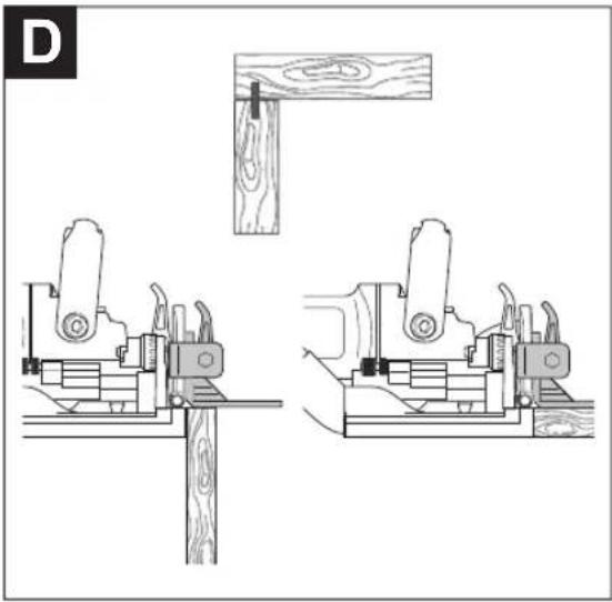
natural_image
Technical line drawing of two mechanical clamping setups with wooden components and mounting brackets (no text or symbols)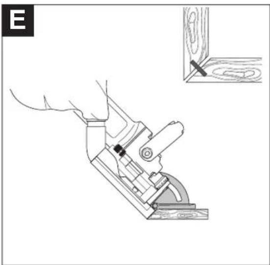
natural_image
Technical line drawing of a mechanical clamp or bracket assembly with a wooden base, showing no text or symbols.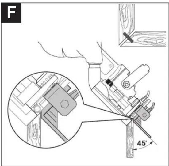
natural_image
Technical illustration showing two mechanical assembly steps: one with a wooden strip and a close-up of the tool, the other with a hand operating a workpiece (no text or symbols present)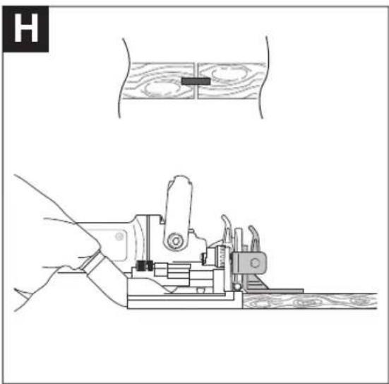
natural_image
Technical illustration showing two mechanical assembly steps: top view of a wooden plank with a rectangular component, bottom view of a hand using a clamp tool (no text or symbols)6
natural_image
Technical line drawing of a wooden cutting machine and its internal mechanism (no text or symbols)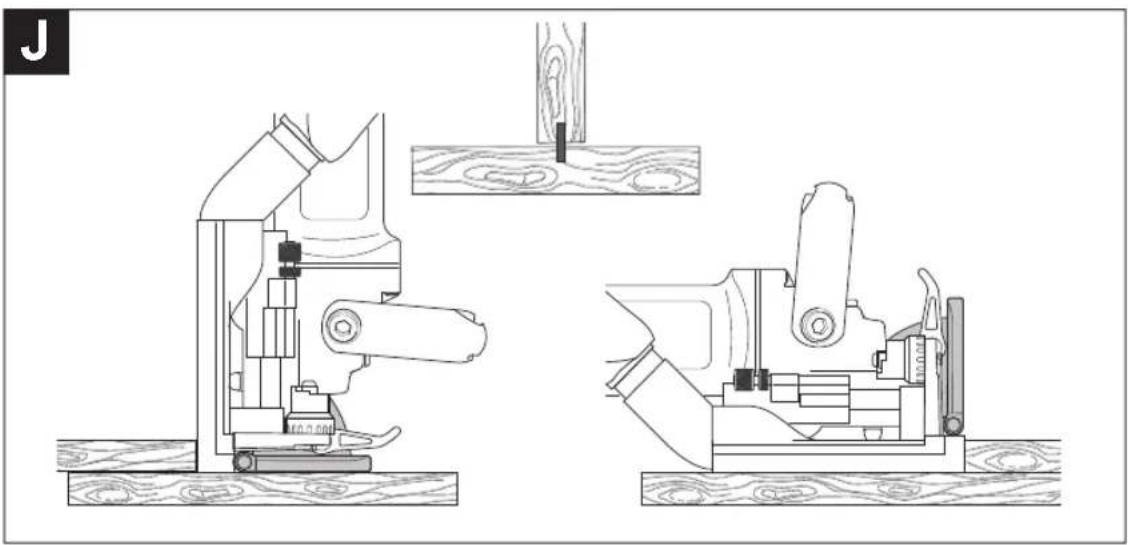
natural_image
Technical line drawing of two mechanical assembly components with wooden base and wood clamps, no text or symbols present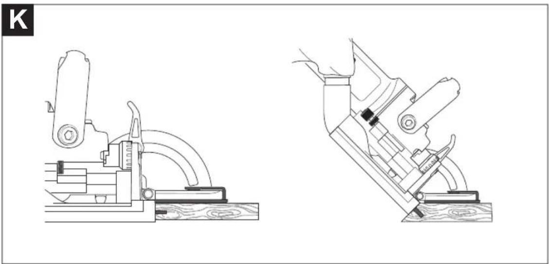
natural_image
Technical line drawings of mechanical clamping devices on wooden base (no text or symbols)Deutsch
Sicherheitshinweise
natural_image
Illustration of hands operating a mechanical device with no visible text or symbolswww.bosch-pt.com/serviceaddresses
Transport
General Power Tool Safety Warnings
WARNING
Read all safety warnings and all instructions. Failure to follow the
warnings and instructions may result in electric shock, fire and/or serious injury.
Save all warnings and instructions for future reference.
The term "power tool" in the warnings refers to your mains-operated (corded) power tool or battery-operated (cordless) power tool.
Work area safety
▶ Keep work area clean and well lit. Cluttered or dark areas invite accidents.
▶ Do not operate power tools in explosive atmospheres, such as in the presence of flammable liquids, gases or dust. Power tools create sparks which may ignite the dust or fumes.
▶ Keep children and bystanders away while operating a power tool. Distractions can cause you to lose control.
Electrical safety
▶ Power tool plugs must match the outlet. Never modify the plug in any way. Do not use any adapter plugs with earthed (grounded) power tools. Unmodified plugs and matching outlets will reduce risk of electric shock.
▶ Avoid body contact with earthed or grounded surfaces, such as pipes, radiators, ranges and refrigerators. There is an increased risk of electric shock if your body is earthed or grounded.
▶ Do not expose power tools to rain or wet conditions. Water entering a power tool will increase the risk of electric shock.
▶ Do not abuse the cord. Never use the cord for carrying, pulling or unplugging the power tool. Keep cord away from heat, oil, sharp edges or moving parts.
Damaged or entangled cords increase the risk of electric shock.
When operating a power tool outdoors, use an extension cord suitable for outdoor use. Use of a cord suitable for outdoor use reduces the risk of electric shock..
▶ If operating a power tool in a damp location is unavoidable, use a residual current device (RCD) protected supply. Use of an RCD reduces the risk of electric shock.
Personal safety
▶ Stay alert, watch what you are doing and use common sense when operating a power tool. Do not use a power tool while you are tired or under the influence of drugs, alcohol or medication. A moment of inattention while operating power tools may result in serious personal injury.
▶ Use personal protective equipment. Always wear eye protection. Protective equipment such as dust mask, non-skid safety shoes, hard hat, or hearing protection used for appropriate conditions will reduce personal injuries.
▶ Prevent unintentional starting. Ensure the switch is in the off-position before connecting to power source and/or battery pack, picking up or carrying the tool.
Carrying power tools with your finger on the switch or energising power tools that have the switch on invites accidents.
16 | English
Remove any adjusting key or wrench before turning the power tool on. A wrench or a key left attached to a rotating part of the power tool may result in personal injury.
▶ Do not overreach. Keep proper footing and balance at all times. This enables better control of the power tool in unexpected situations.
▶ Dress properly. Do not wear loose clothing or jewellery. Keep your hair, clothing and gloves away from moving parts. Loose clothes, jewellery or long hair can be caught in moving parts.
If devices are provided for the connection of dust extraction and collection facilities, ensure these are connected and properly used. Use of dust collection can reduce dust-related hazards.
Power tool use and care
▶ Do not force the power tool. Use the correct power tool for your application. The correct power tool will do the job better and safer at the rate for which it was designed.
▶ Do not use the power tool if the switch does not turn it on and off. Any power tool that cannot be controlled with the switch is dangerous and must be repaired.
▶ Disconnect the plug from the power source and/or the battery pack from the power tool before making any adjustments, changing accessories, or storing power tools. Such preventive safety measures reduce the risk of starting the power tool accidentally.
▶ Store idle power tools out of the reach of children and do not allow persons unfamiliar with the power tool or these instructions to operate the power tool. Power tools are dangerous in the hands of untrained users.
- Maintain power tools. Check for misalignment or binding of moving parts, breakage of parts and any other condition that may affect the power tool's operation. If damaged, have the power tool repaired before use. Many accidents are caused by poorly maintained power tools.
▶ Keep cutting tools sharp and clean. Properly maintained cutting tools with sharp cutting edges are less likely to bind and are easier to control.
▶ Use the power tool, accessories and tool bits etc. in accordance with these instructions, taking into account the working conditions and the work to be performed. Use of the power tool for operations different from those intended could result in a hazardous situation.
Battery tool use and care
▶ Recharge only with the charger specified by the manufacturer. A charger that is suitable for one type of battery pack may create a risk of fire when used with another battery pack.
▶ Use power tools only with specifically designated battery packs. Use of any other battery packs may create a risk of injury and fire.
When battery pack is not in use, keep it away from other metal objects, like paper clips, coins, keys, nails, screws or other small metal objects, that can make a connection from one terminal to another. Shorting the battery terminals together may cause burns or a fire.
▶ Under abusive conditions, liquid may be ejected from the battery; avoid contact. If contact accidentally occurs, flush with water. If liquid contacts eyes, additionally seek medical help. Liquid ejected from the battery may cause irritation or burns.
Service
▶ Have your power tool serviced by a qualified repair person using only identical replacement parts. This will ensure that the safety of the power tool is maintained.
Joints safety warnings
▶ Disc cutters must be rated for at least the speed marked on the tool. Disc cutters running over rated speed can fly apart and cause injury.
▶ Always use the guard. The guard protects the operator from broken disc cutter fragments and unintentional contact with the disc cutter.
▶ Always use side milling cutters of the correct size and shape and with the correct locating bore. Side milling cutters that do not match the mounting hardware of the router will run eccentrically, causing loss of control.
▶ Only bring the power tool into contact with the workpiece when switched on. Otherwise there is danger of kickback if the cutting tool jams in the workpiece.
▶ Do not put your hands in the routing area or close to the router. Grip the auxiliary handle with your other hand. Holding the router with both hands avoids injury.
▶ Never rout over metal objects, nails or screws. The router could become damaged and cause increased vibration.
▶ Use suitable detectors to determine if there are hidden supply lines or contact the local utility company for assistance. Contact with electric cables can cause fire and electric shock. Damaging gas lines can lead to explosion. Breaking water pipes causes property damage.
▶ Do not use blunt or damaged routers. Blunt or damaged routers cause increased friction, create imbalances and may become jammed.
When working with the tool, always hold it firmly with both hands and provide for a secure stance. The power tool is guided more secure with both hands.
- Secure the workpiece. A workpiece clamped with clamping devices or in a vice is held more secure than by hand.
▶ Always wait until the power tool has come to a complete stop before placing it down. The application tool can jam and cause you to lose control of the power tool.
▶ Always use the auxiliary handle supplied with the power tool. Loss of control can cause personal injury.
▶ Only use the application tools listed in this operating manual. Do not use cutting discs or circular saw blades.
▶ Check that the side milling cutter is firmly secured before starting operation.
▶ Only press the spindle lock button when the power tool is at a standstill. Otherwise, the power tool may become damaged.
▶ Only use the power tool when the anti-slip protection is fitted. This ensures that precise work can be carried out with the power tool.
In case of damage and improper use of the battery, vapours may be emitted. The battery can set alight or explode. Ensure the area is well ventilated and seek medical attention should you experience any adverse effects. The vapours may irritate the respiratory system.
▶ Do not modify or open the battery. There is a risk of short-circuiting.
The battery can be damaged by pointed objects such as nails or screwdrivers or by force applied externally. An internal short circuit may occur, causing the battery to burn, smoke, explode or overheat.
▶ Only use the battery in the manufacturer's products. This is the only way in which you can protect the battery against dangerous overload.


Protect the battery against heat, e.g. against continuous intense sunlight, fire, dirt, water and moisture. There is a risk of explosion and short-circuiting.
Product Description and Specifications

Read all the safety and general instructions.
Failure to observe the safety and general instructions may result in electric shock, fire and/or serious injury.
Please observe the illustrations at the beginning of this operating manual.
Intended Use
The power tool is designed to create slots for biscuit joints in chipboard, hardwood, softwood, plywood and fibreboard.
Product Features
The numbering of the product features refers to the diagram of the power tool on the graphics page.
(1) Handle (insulated gripping surface)
(2) On/off switch
(3) Angle guide clamping lever
(4) Height scale
(5) Angle scale
(6) Horizontal centre mark
(7) Anti-slip protection
(8) Adjustment knob for the height-adjustable stop
(9) Height-adjustable stop
(10) Routing width mark
(11) Vertical centre mark
(12) Clamping lever for the height-adjustable stop
(13) Direction of rotation arrow on housing
(14) Spindle lock button
(15) Auxiliary handle (insulated gripping surface)
(16) Rechargeable battery ^a
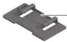
(17) Clip-on plate
(18) Angle guide
(19) Adjustment knob for routing depth
(20) Locking nut for routing depth adjustment
(21) Adjusting screw for routing depth adjustment
(22) Extraction outlet
(23) Dust bag
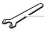
(24) Two-hole spanner
(25) Clamping nut
(26) Side milling cutter
(27) Direction of rotation arrow for side milling cutter
(28) Centring collar on the mounting flange
(29) Mounting flange
(30) Routing spindle
(31) Direction of rotation arrow for routing spindle
(32) Lock washer for the base plate
(33) Clamping screw for the base plate
(34) Base plate
(35) Rechargeable battery release button ^4
a) This accessory described here is not included with the product as standard. The items included are indicated on the packaging.
Technical Data
| Biscuit joiner GFF 18V-22 | ||
| Article number | 3 601 F20 1.. | |
| Rated voltage V= 18 | ||
| Rated no-load speed ^a) | min ^-1 | 11000 |
| Max. routing depth ^b) | mm 22 | |
| Spindle thread mm M10 x 1.25 | ||
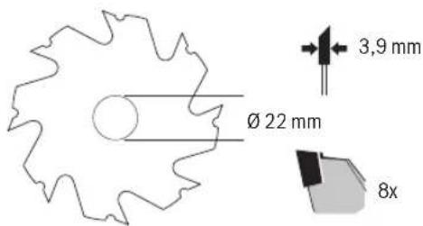
| Side milling cutter drilling diameter | mm 22 | |
| Max. diameter of side milling cutter | mm 105 | |
| Max. thickness of side milling cutter | mm | 4 |
| Weight according to EPTA-Procedure 01:2014 ^c) | kg 3.0–4.0 | |
18 | English
Biscuit joiner GFF 18V-22
| Recommended ambient temperature during charging | °C 0 to +35 |
| Permitted ambient temperature during operation ^D) and during storage | °C -15 to +50 |
| Recommended rechargeable batteries | GBA 18V...ProCORE18V... |
| Recommended battery chargers | GAL 18...GAX 18...GAL 36... |
A) The actual no-load speed must not exceed the rated no-load speed and is therefore lower.
B) achieved with a side milling cutter with a 105 mm diameter
C) Depends on battery in use
D) Limited performance at temperatures < 0 °C
Values can vary depending on the product, scope of application and environmental conditions. To find out more, visit www.bosch-professional.com/wac.
Noise/Vibration Information
Noise emission values determined according to EN 60745-2-19.
Typically, the A-weighted noise level of the power tool is: Sound pressure level 80 dB(A); sound power level 91 dB(A). Uncertainty K = 3 dB.
Wear hearing protection!
Vibration total values a_h (triax vector sum) and uncertainty K determined according to EN 60745-2-19:
a_n<2.5 m/s^2,K=1.5 m/s^2.
The vibration level given in these instructions has been measured in accordance with a standardised measuring procedure and may be used to compare power tools. It can also be used for a preliminary estimation of exposure to vibration.
The stated vibration level applies to the main applications of the power tool. However, if the power tool is used for different applications, with different application tools or poorly maintained, the vibration level may differ. This can significantly increase the exposure to vibration over the total working period.
To estimate the exposure to vibration accurately, the times when the tool is switched off or when it is running but not actually being used should also be taken into account. This can significantly reduce the exposure to vibration over the total working period.
Implement additional safety measures to protect the operator from the effects of vibration, such as servicing the power tool and application tools, keeping the hands warm, and organising workflows correctly.
Rechargeable battery
Bosch sells some cordless power tools without a rechargeable battery. You can tell whether a rechargeable battery is included with the power tool by looking at the packaging.
Charging the battery
▶ Use only the chargers listed in the technical data. Only these chargers are matched to the lithium-ion battery of your power tool.
Note: Lithium-ion rechargeable batteries are supplied partially charged according to international transport regulations. To ensure full rechargeable battery capacity, fully charge the rechargeable battery before using your tool for the first time.
Inserting the Battery
Push the charged battery into the battery holder until it clicks into place.
Removing the Battery
Note: Only remove the battery when the power tool is switched off.
To remove the rechargeable battery, press the battery release button and pull the battery out. Do not use force to do this.
The rechargeable battery has two locking levels to prevent the battery from falling out if the battery release button is pressed unintentionally. The rechargeable battery is held in place by a spring when fitted in the power tool.
Battery charge indicator
The green LEDs on the battery charge indicator indicate the state of charge of the battery. For safety reasons, it is only possible to check the state of charge when the power tool is not in operation.
Press the button for the battery charge indicator or to show the state of charge. This is also possible when the battery is removed.
If no LED lights up after pressing the button for the battery charge indicator, then the battery is defective and must be replaced.
Battery model GBA 18V...

LED Capacity
| 3× continuous green light 60-100% |
| 2× continuous green light 30-60% |
| 1× continuous green light 5-30% |
| 1× flashing green light 0-5% |
Battery model ProCORE18V...
LED Capacity
| 5 × continuous green light 80-100 % |
| 4 × continuous green light 60-80 % |
| 3 × continuous green light 40-60 % |
LED Capacity
2 × continuous green light 20–40 %
1 × continuous green light 5–20%
1 × flashing green light 0–5 %
Recommendations for Optimal Handling of the Battery
Protect the battery against moisture and water.
Only store the battery within a temperature range of -20 to 50 °C. Do not leave the battery in your car in the summer, for example.
Occasionally clean the ventilation slots on the battery using a soft brush that is clean and dry.
A significantly reduced operating time after charging indicates that the battery has deteriorated and must be replaced. Follow the instructions on correct disposal.
Fitting
Inserting/Replacing the Side Milling Cutter (see figures A–B)
Before carrying out any work on the power tool (e.g. maintenance, tool change etc.), remove the battery from the power tool. There is risk of injury from unintentionally pressing the on/off switch.
▶ Wearing protective gloves is recommended for inserting and replacing side milling cutters.
▶ Protect the side milling cutter from shock and impact.
The power tool can be operated with the Bosch side milling cutter 3 608 641 013 (105 mm diameter) or a commercially available side milling cutter with the same or a smaller diameter (< 105 mm).
- If necessary, set the angle guide (18) to 0^ (see "Setting the Routing Angle", page 20) and set the height-adjustable stop (9) to the maximum height (see "Setting the Height-Adjustable Stop", page 20).
- Turn the power tool so that the base plate (34) faces upward.
- Loosen the clamping screw (33) by approx. three turns.
- Open up the base plate (34). Hold the power tool in such a way that the base plate does not fold back down.
- Press and hold the spindle lock button (14).
- Loosen the clamping nut (25) with the supplied two-pin spanner (24) and remove the nut.
- If necessary, remove the inserted side milling cutter (26) and clean it.
- If necessary, remove the inserted mounting flange (29) and clean it.
-
Place the mounting flange (29) on the routing spindle (30) so that the centring collar (28) (diameter 22 mm) is on the top. The mounting flange must lock into the flats of the routing spindle (anti-twist protection).
-
Place the clean side milling cutter (26) on the mounting flange (29) as shown in the figure, so that the direction of rotation arrow (27) is visible on the side milling cutter and matches the direction of rotation arrow on the routing spindle (31). The locating bore of the side milling cutter must lock into the centring collar (28) of the mounting flange.
- Screw the clamping nut (25) onto the routing spindle (30). Using the two-hole spanner (24), firmly tighten the clamping nut while pressing the spindle lock button (14).
▶ Check that the side milling cutter is correctly attached and can turn freely.
- Close the base plate (34). Ensure that the lock washer (32) is positioned above the base plate.
- Tighten the clamping screw (33).
▶ Check that the base plate (34) is locked firmly in place.
Dust/Chip Extraction
The dust from materials such as lead paint, some types of wood, minerals and metal can be harmful to human health. Touching or breathing in this dust can trigger allergic reactions and/or cause respiratory illnesses in the user or in people in the near vicinity.
Certain dusts, such as oak or beech dust, are classified as carcinogenic, especially in conjunction with wood treatment additives (chromate, wood preservative). Materials containing asbestos may only be machined by specialists.
- Use a dust extraction system that is suitable for the material wherever possible.
- Provide good ventilation at the workplace.
- It is advisable to wear a P2 filter class breathing mask.
The regulations on the material being machined that apply in the country of use must be observed.
- Avoid dust accumulation at the workplace. Dust can easily ignite.
Clean the extraction outlet (22) if necessary. To do this, open the base plate (34) (see "Inserting/Replacing the Side Milling Cutter (see figures A-B)", page 19) and pull out the extraction outlet.
External Dust Extraction (see accessories page)
Insert the connector of an extraction hose (accessory) onto the extraction outlet (22), turning slightly. Connect the extraction hose to a vacuum cleaner.
The dust extractor must be suitable for the material being worked.
When extracting dry dust or dust that is especially detrimental to health or carcinogenic, use a special dust extractor.
Self-generated dust extraction with dust bag (see accessories page)
For smaller routing jobs, you can use the dust bag (23). Insert the connector of the dust bag (23) onto the extraction outlet (22), turning slightly.
20 | English
Empty the dust bag (23) at regular intervals to maintain optimum dust collection.
Do this by pulling off the dust bag (23), opening the zip and emptying the contents.
Operation
Setting the Routing Depth
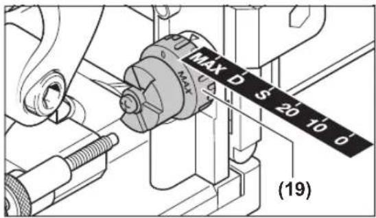
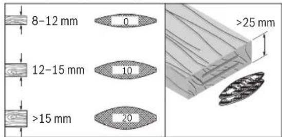
Use the adjustment knob (19) to set the routing depth. The adjustment knob has lock-in heights for six sizes of jointing biscuit.
Assigning the lock-in heights to jointing biscuits and routing depths:
Lock-in height Jointing biscuit Routing depth in mm ^A)
| 0 No. 0 8 | |
| 10 No. 10 10 | |
| 20 No. 20 12.3 | |
| S Simplex 13 | |
| D Duplex 14.7 | |
| MAX - 22 |
A) achieved with a side milling cutter with a 105 mm diameter. When using resharpened side milling cutters or side milling cutters with a smaller diameter (< 105 mm), it may be necessary to readjust the routing depth. Do this by loosening the locking nut (20). Turn the adjusting screw (21) clockwise to reduce the routing depth or anticlockwise to increase it. Perform a test run to check the routing depth adjustment. Then retighten the locking nut (20) firmly.
Setting the Height-Adjustable Stop
Using the height-adjustable stop (9), you can specify the distance between the top of the workpiece and the slot being routed.
To attach the height-adjustable stop (9), place it on the angle guide (18) and turn it into the guide groove of the angle guide using the adjustment knob (8).
Note: Do not apply force to attach it. If correctly positioned, the stop (9) runs smoothly.
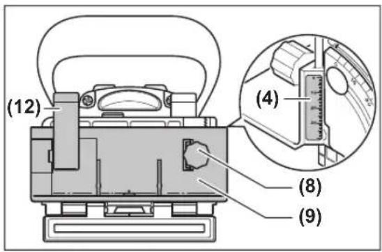
Using the adjustment knob (8), set the required distance on the height scale (4). Then tighten the clamping lever (12).
To ensure the slot is positioned in the centre of a workpiece, you must set the height-adjustable stop at half the workpiece thickness.
Example: For an 18 mm thick workpiece, set the height scale at 9 mm.
To remove the height-adjustable stop (9), loosen the clamping lever (12) and unscrew the stop, with the adjustment knob (8) facing upwards, all the way out of the angle guide (18).
Setting the Routing Angle
The angle guide (18) makes routing on mitres/bevels easier.
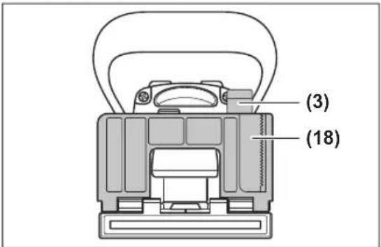
To adjust the angle guide (18), loosen the clamping lever (3). Tilt the angle guide until the required angle is set on the angle scale (5) (there are lock-in points at 0°, 30°, 45°, 60° and 90°). Then tighten the clamping lever (3).
▶ Take care to ensure that neither the height-adjustable stop (9) nor the clip-on plate (17) are located in the exit area of the side milling cutter once the routing angle has been set. To check, switch the power tool off and push the router exit against the edge of a table, for instance, until the side milling cutter is visible. The most extended side milling cutter must not make contact with the height-adjustable stop (9) or the clip-on plate (17).
Start-Up
▶ Before carrying out any work on the power tool (e.g. maintenance, tool change etc.), remove the battery
from the power tool. There is risk of injury from unintentionally pressing the on/off switch.
Before the power tool can be switched on, the base plate (34) must be locked firmly in place by the clamping screw (33) and the lock washer (32).
▶ Before switching on, check whether the automatic reset function on the motor unit is working correctly.
Push the router exit against the edge of a table, for instance, until the side milling cutter is visible. When the pressure is released, the side milling cutter must be fully withdrawn into the base plate.
Switching On and Off
To switch on the power tool, push the on/off switch (2) forward and push it forwards and down to lock it.
To switch off the power tool, push the on/off switch (2) backwards so that it jumps back into the off position.
Restart protection
The restart protection feature prevents the power tool from uncontrolled starting after the power supply to it has been interrupted.
To restart the tool, set the on/off switch (2) to the off position and then switch the power tool on again.
Soft start
The electronic soft start limits the torque when the power tool is switched on and increases the service life of the motor.
Working Advice
▶ When working with the machine, always hold it firmly with both hands and provide for a secure stance. The power tool is guided more secure with both hands.
▶ Do not put your hands in the routing area or close to the side milling cutter.

natural_image
Illustration of hands operating a mechanical device with a tool (no text or symbols visible)When working, hold the handle (1) in one hand, and the auxiliary handle (15) in the other hand.
▶ Only bring the power tool into contact with the workpiece when switched on. Otherwise there is danger of kickback if the cutting tool jams in the workpiece.
Carry out the routing process with a uniform feed.
Establishing the Routing Position
The vertical centre mark (11) on the angle guide and height guide indicates the centre of the slot (perpendicular to the side milling cutter). The maximum width of the slot is indicated by both marks (10) on the height-adjustable stop (9).
When positioning the height, the horizontal centre mark (6) on the base plate is useful, because it indicates the horizontal centre of the side milling cutter.
The arrow (13) on the power tool housing indicates the rotational direction of the side milling cutter.
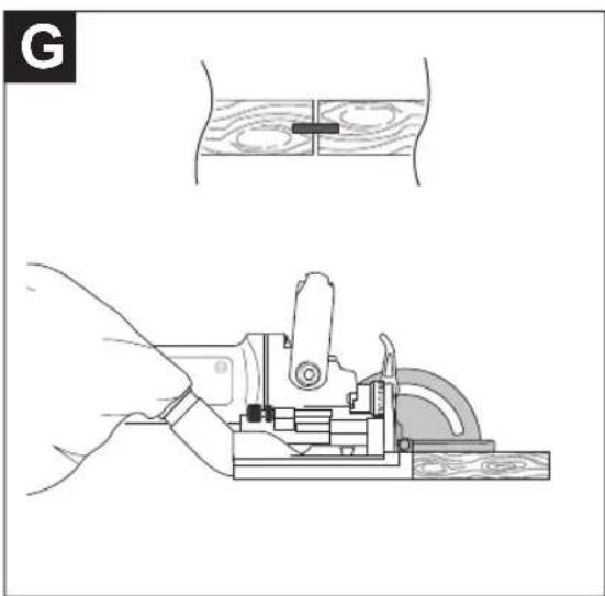
Routing Tongue-and-Groove Joints
Examples of the following types of joint can be found on the graphics pages:
- Corner joints: with angle guide see figure C, with height-adjustable stop see figure D
- Mitre/bevel joints: with angle guide see figure E, with height-adjustable stop see figure F
- Longitudinal and transverse joints: with angle guide see figure G, with height-adjustable stop see figure H
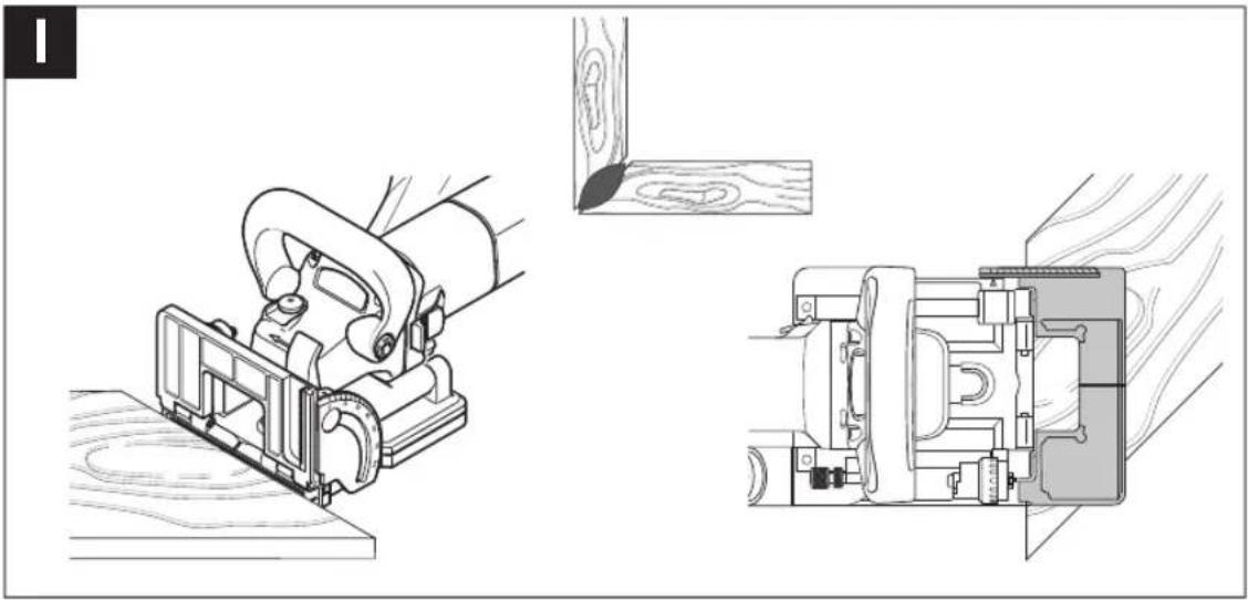
- Frame joints: see figure I
- Mid-wall joints: see figure J
Selecting the Right Jointing Biscuit
For a solid connection, use the largest possible jointing biscuits (slats). The Bosch range of accessories includes suitable jointing biscuits (see accessories page at the end of the operating instructions).
Routing Thin Workpieces (see figure K)
To rout workpieces less than 16 mm in thickness, place the clip-on plate (17) on the angle guide (18). This ensures that the slot is not too close to the top of the workpiece. When calculating the horizontal routing position, take into account the thickness of the clip-on plate.
Use the clip-on plate (17) to ensure the slot is not too deep, including on mitre/bevel joints on thin workpieces.
Routing Narrow Workpieces
When routing narrow workpieces, use the height-adjustable stop (9) if possible. Make sure that the maximum routing width marks (10) on it do not exceed the workpiece.
Maintenance and Service
Maintenance and Cleaning
Before carrying out any work on the power tool (e.g. maintenance, tool change etc.), remove the battery from the power tool. There is risk of injury from unintentionally pressing the on/off switch.
▶ To ensure safe and efficient operation, always keep the power tool and the ventilation slots clean.
22 | Français
If necessary, clean and grease the guides. Use only non-resinous oil for this purpose (e.g. sewing machine oil).
Retightening the Clamping Lever
You can readjust the clamping force of the clamping levers (3) and (12) as required. To do this, loosen the clamping levers and unscrew them. Position the clamping lever, offset at least 30^ anticlockwise, and retighten it.
After-Sales Service and Application Service
Our after-sales service responds to your questions concerning maintenance and repair of your product as well as spare parts. You can find explosion drawings and information on spare parts at: www.bosch-pt.com
The Bosch product use advice team will be happy to help you with any questions about our products and their accessories.
In all correspondence and spare parts orders, please always include the 10-digit article number given on the nameplate of the product.
Great Britain
Robert Bosch Ltd. (B.S.C.)
P.O. Box 98
Broadwater Park
North Orbital Road
Denham Uxbridge
UB 9 5HJ
At www.bosch-pt.co.uk you can order spare parts or arrange the collection of a product in need of servicing or repair.
Tel. Service: (0344) 7360109
E-Mail: boschservicecentre@bosch.com
You can find further service addresses at:
www.bosch-pt.com/serviceaddresses
Transport
The recommended lithium-ion batteries are subject to legislation on the transport of dangerous goods. The user can transport the batteries by road without further requirements.
When the batteries are shipped by third parties (e.g. air transport or forwarding agency), special requirements on packaging and labelling (e.g. ADR regulations) must be met. A dangerous goods expert must be consulted when preparing the items for shipping.
Dispatch battery packs only when the housing is undamaged. Tape or mask off open contacts and pack up the battery in such a manner that it cannot move around in the packaging. Please also observe the possibility of more detailed national regulations.
Disposal

Power tools, rechargeable batteries, accessories and packaging should be sorted for environmental-friendly recycling.
Do not dispose of power tools and batteries/re-chargeable batteries into household waste!
Only for EU countries:
According to the Directive 2012/19/EU on waste electrical and electronic equipment and its transposition into national law, power tools that are no longer usable, and, according to the Directive 2006/66/EC, defective or drained batteries must be collected separately and disposed of in an environmentally correct manner.
If disposed incorrectly, waste electrical and electronic equipment may have harmful effects on the environment and human health, due to the potential presence of hazardous substances.
Only for United Kingdom:
According to The Waste Electrical and Electronic Equipment Regulations 2013 (SI 2013/3113) (as amended) and the Waste Batteries and Accumulators Regulations 2009 (SI 2009/890) (as amended), products that are no longer usable must be collected separately and disposed of in an environmentally friendly manner.
Battery packs/batteries:
Li-ion:
Please observe the notes in the section on transport (see "Transport", page 22).
Français
natural_image
Illustration of a hand using a mechanical tool to adjust or install a component (no text or symbols visible)Robert Bosch (France) S.A.S.
www.bosch-pt.com/serviceaddresses
Transport
natural_image
Illustration of hands operating a mechanical device with no visible text or symbolsCalle Robert Bosch No. 405
www.bosch-pt.com/serviceaddresses
Transporte
natural_image
Illustration of a hand operating a mechanical device with a tool (no text or symbols visible)www.bosch-pt.com/serviceaddresses
Transporte
natural_image
Illustration of a hand operating a mechanical device with no visible text or symbolswww.bosch-pt.com/serviceaddresses
Trasporto
natural_image
Illustration of hands operating a mechanical device with no visible text or symbolswww.bosch-pt.com/serviceaddresses
Vervoer
natural_image
Illustration of hands operating a mechanical device with a tool (no text or symbols visible)Bosch Service Center
Telegrafvej 3
2750 Ballerup
På www.bosch-pt.dk kan der online bestilles reservedele eller oprettes en reparations ordre.
Tlf. Service Center: 44898855
Fax: 44898755
E-Mail: vaerktoej@dk.bosch.com
www.bosch-pt.com/serviceaddresses
70 | Svensk
Transport
natural_image
Illustration of hands operating a mechanical device with a tool (no text or symbols visible)Bosch Service Center
Telegrafvej 3
2750 Ballerup
Danmark
Tel.: (08) 7501820 (inom Sverige)
Fax: (011) 187691
www.bosch-pt.com/serviceaddresses
Transport
natural_image
Illustration of hands using a tool to adjust or install a mechanical component (no text or symbols visible)www.bosch-pt.com/serviceaddresses
Transport
natural_image
Illustration of hands operating a mechanical device with no visible text or symbolswww.bosch-pt.com/serviceaddresses
Kuljetus
natural_image
Illustration of hands operating a mechanical device with no visible text or symbolswww.bosch-pt.com/serviceaddresses
Μεταφορά
natural_image
Illustration of a hand operating a mechanical device with a tool (no text or symbols visible)www.bosch-pt.com/serviceaddresses
Nakliye
natural_image
Illustration of hands operating a mechanical device with a tool (no text or symbols visible)Robert Bosch Sp. z o.o.
www.bosch-pt.com/serviceaddresses
Transport
natural_image
Illustration of hands operating a mechanical device with a tool (no text or symbols visible)Bosch Service Center PT
K Vápence 1621/16
692 01 Mikulov
www.bosch-pt.com/serviceaddresses
Přeprava
natural_image
Illustration of hands operating a mechanical device with a tool (no text or symbols visible)www.bosch-pt.com/serviceaddresses
Transport
natural_image
Illustration of hands operating a mechanical device with no visible text or symbolswww.bosch-pt.com/serviceaddresses
Szállítás
natural_image
Illustration of hands operating a mechanical device with no visible text or symbols148 | Русский
www.bosch-pt.com/serviceaddresses
natural_image
Illustration of hands operating a mechanical device with no visible text or symbolswww.bosch-pt.com/serviceaddresses
Транспортування
natural_image
Illustration of hands operating a mechanical device with a tool (no text or symbols visible)www.bosch-pt.com/serviceaddresses
natural_image
Illustration of hands operating a mechanical device with no visible text or symbolsService scule electrice
Strada Horia Măcelariu Nr. 30-34, sector 1
013937 Bucureşti
www.bosch-pt.com/serviceaddresses
Transport
natural_image
Illustration of hands operating a mechanical device with no visible text or symbolsService scule electrice
Strada Horia Măcelariu Nr. 30-34, sector 1
013937 Bucureşti, România
www.bosch-pt.com/bg/bg/
www.bosch-pt.com/serviceaddresses
Транспортиране
natural_image
Illustration of hands operating a mechanical device with no visible text or symbolswww.bosch-pt.com/serviceaddresses
Транспорт
Pomoću obrtnog dugmeta (19) možete da definišete dubinu glodanja. Obrtno dugme ima visine za šest veličina pljosnatih tiplova.
Dodela visina za pljosnate tiplove i dubine glodanja:
| Visina Pljosnati tiplovi Dubina glodanja u mmA) | |
| 0 Br. 0 8 | |
| 10 Br. 10 10 | |
| 20 Br. 20 12,3 | |
| S Simplex 13 | |
| D Duplex 14,7 | |
Visina Pljosnati tiplovi Dubina glodanja u mm ^A)
MAX-22
A) Postignuto disk-gladalicom prečnika 105 mm Ako koristite naoštrene disk-glodalice ili koristite disk-glodalice manjeg prečnika (<105 mm), morate eventualno da dodatno podesite dubinu glodanja. Za to otpustite sigurnosnu navrtku (20). Okretanjem zavrtnja za podešavanje (21) u smeru kretanja kazaljki na satu možete da smanjite dubinu glodanja odn. povećate okretanjem suprotno od smera kretanja kazaljki na satu. Pomoću probnih glodanja proverite podešenu dubinu glodanja. Potom ponovo dobro zavrnite sigurnosnu navrtku (20).
Podešavanje graničnika koji je podesiv po visini
Pomoću graničnika koji je podesiv po visini (9) možete da definišete rastojanje između gornje strane radnog komada i žleba koji obrađujete glodanjem.
Za montažu graničnika koji je podesiv po visini (9) stavite ga na ugaoni graničnik (18) i okrenite ga pomoću obrtnog dugmeta (8) u vodicu ugaonog graničnika.
natural_image
Illustration of hands operating a mechanical device with no visible text or symbolsTokom rada jednom rukom držite ručku (1), a drugom rukom dodatnu ručku (15).
Vodite električni alat samo uključen na radni komad. Inače postoji opasnost od povratnog udarca, ako upotrebljeni alat zapne u radnom komadu.
Izvodite glodanje sa ravnomernim pomeranjem napred.
www.bosch-pt.com/serviceaddresses
Transport
Preporučeni litijum-jonski akumulatori podležu zahtevima propisa o opasnim materijama. Korisnik može bez dodatnih uslova transportovati akumulatore na drumu.
Kod slanja preko trećih lica (na primer vazdušnim transportom ili špedicijom) mora se obratiti pažnja na posebne zahteve u pogledu pakovanja i označavanja. Tada se kod pripreme paketa za slanje mora pozvati stručnjak za opasne materije.
Akumulatorske baterije šaljite samo ako kućište nije oštećeno. Odlepite otvorene kontakte i upakujte akumulatorsku bateriju tako, da se ne pokreće u paketu.
Molimo da obratite pažnju na eventualne dalje nationalne propise.
Uklanjanje dubreta

Električne alate, akumulacione baterije, pribor i pakovanja treba predati na reciklažu koja je u skladu sa zaštitom životne sredine.
Ne bacajte električne alate i akumulatore/baterije u kućno djubre!
Samo za EU-zemlje:
Prema evropskoj direktivi 2012/19/EU o starim električnim i elektronskim uređajima i njenoj primeni u nacionalnom pravu, električni alati koji se više ne mogu koristiti, a prema evropskoj direktivi 2006/66/EC akumulatori/baterije koje su u kvaru ili istrošene moraju se odvojeno sakupljati i uključiti u reciklažu koja ispunjava ekološke uslove.
natural_image
Illustration of a hand using a tool to adjust or install a mechanical component (no text or symbols visible)www.bosch-pt.com/serviceaddresses
Transport
Okretnim gumbom (19) možete odrediti dubinu glodanja.
Okretni gumb ima visine uglavljivanja za šest veličina plosnatih tipli.
natural_image
Illustration of hands operating a mechanical device with no visible text or symbolswww.bosch-pt.com/serviceaddresses
Transport
natural_image
Illustration of hands operating a mechanical device with no visible text or symbolswww.bosch-pt.com/serviceaddresses
Transport
natural_image
Illustration of hands operating a mechanical device with no visible text or symbolsStrādājot ar vienu roku, turiet rokturi (1), bet ar otru roku - papildrokturi. (15).
www.bosch-pt.com/serviceaddresses
Transportešana
natural_image
Illustration of hands operating a mechanical device with no visible text or symbolsnatural_image
Illustration of a hand using a sewing machine to adjust or install components (no text or symbols visible)www.bosch-pt.com/serviceaddresses
운반
natural_image
Illustration of hands operating a mechanical device with no visible text or symbolsRobert Bosch Morocco SARL
53.شارع الملازم محمد محرود
20300 الدار البيضاء
www.bosch-pt.com/serviceaddresses
النقل
Correctional Islamic Governmental Governmental Governmental Governmental Governmental Governmental Governmental Governmental Governmental Governmental Governmental Governmental Governmental Governmental Governmental Governmental Governmental Governmental Governmental Governmental Governmental Governmental Governmental Governmental Governmental Governmental Governmental Governmental Governmental Governmental Governmental Governmental Governmental Governmental Governmental Governmental Governmental Governmental Governmental Governmental Governmental Governmental Governmental Governmental Governmental Governmental Governmental Governmental Governmental Governmental Governmenta
natural_image
Illustration of hands operating a mechanical device with no visible text or symbolsnatural_image
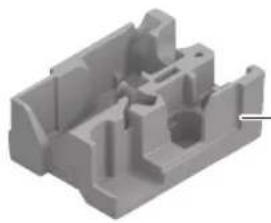
3D rendering of a mechanical component with labeled HDSOB (no other text or symbols visible)L-Boxx 238
1 600 A01 2G2
3 605 700 154
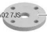
natural_image
3D rendered mechanical component with cutouts and mounting holes (no text or symbols)1 600 A02 WZ9 1 600 A02 7JS
1607950043
1 600 A02 LR1
3 608 641 013
0 (45 mm x 15 mm x 4 mm):
2 607 000 147 (1000x)
2 607 000 796 (50x)
10 (55 mm x 19 mm x 4 mm):
2 607 000 148 (1000x)
2 607 000 797 (50x)
20 (60 mm x 23 mm x 4 mm):
2 607 000 149 (1000x)
2 607 000 103 (50x)
Licenses
Copyright © 2015, Infineon Technologies AG
All rights reserved.
Redistribution and use in source and binary forms, with or without modification, are permitted provided that the following conditions are met:
- Redistributions of source code must retain the above copyright notice, this list of conditions and the following disclaimer.
- Redistributions in binary form must reproduce the above copyright notice, this list of conditions and the following disclaimer in the documentation and/or other materials provided with the distribution.
- Neither the name of the copyright holders nor the names of its contributors may be used to endorse or promote products derived from this software without specific prior written permission.
THIS SOFTWARE IS PROVIDED BY THE COPYRIGHT HOLDERS AND CONTRIBUTORS "AS IS" AND ANY EXPRESS OR IMPLIED WARRANTIES, INCLUDING, BUT NOT LIMITED TO, THE IMPLIED WARRANTIES OF MERCHANTABILITY AND FITNESS FOR A PARTICULAR PURPOSE ARE DISCLAIMED. IN NO EVENT SHALL THE COPYRIGHT OWNER OR CONTRIBUTORS BE LIABLE FOR ANY DIRECT, INDIRECT, INCIDENTAL, SPECIAL, EXEMPLARY, OR CONSEQUENTIAL DAMAGES (INCLUDING, BUT NOT LIMITED TO, PROCUREMENT OF SUBSTITUTE GOODS OR SERVICES; LOSS OF USE, DATA, OR PROFITS; OR BUSINESS INTERRUPTION) HOWEVER CAUSED AND ON ANY THEORY OF LIABILITY, WHETHER IN CONTRACT, STRICT LIABILITY, OR TORT (INCLUDING NEGLIGENCE OR OTHERWISE) ARISING IN ANY WAY OUT OF THE USE OF THIS SOFTWARE, EVEN IF ADVISED OF THE POSSIBILITY OF SUCH DAMAGE.
Warranty Disclaimer
This product contains Open Source Software components which underly Open Source Software Licenses. Please note that Open Source Licenses contain disclaimer clauses. The text of the Open Source Licenses that apply are included in this manual under "Licenses".
266 | Licenses
CE
|
| de | EU-Konformitätserklärung | Wir erklären in alleiniger Verantwortung, dass die genannten Produkte allen einschlägigen Bestimmungen der nachfolgend aufgeführten Richtlinien und Verordnungen entsprechen und mit folgenden Normen übereinstimmen.Technische Unterlagen bei:* | |
| Flachdübelfräse | Sachnummer | ||
| en | EU Declaration of Conformity | We declare under our sole responsibility that the stated products comply with all applicable provisions of the directives and regulations listed below and are in conformity with the following standards.Technical file at:* | |
| Biscuit Jointer | Article number | ||
| fr | Déclaration de conformité UE | Nous déclarons sous notre propre responsabilité que les produits décrits sont en conformité avec les directives, règlements normatifs et normes énumérés ci-dessous.Dossier technique auprès de:* | |
| Fraiseuse à lamelles | N° d'article | ||
| es | Declaración de conformidad UE | Declaramos bajo nuestra exclusiva responsabilidad, que los productos nombrados cumplen con todas las disposiciones correspondientes de las Directivas y los Reglamentos mencionados a continuación y están en conformidad con las siguientes normas.Documentos técnicos de:* | |
| Fresa para tacos planos | N° de artículo | ||
| pt | Declaração de Conformidade UE | Declaramos sob nossa exclusiva responsabilidade que os produtos mencionados cumprem todas as disposições e os regulamentos indicados e estão em conformidade com as seguintes normas.Documentação técnica pertencente à:* | |
| Fresadora para buchas planas | N.° do produto | ||
| it | Dichiarazione di conformità UE | Dichiariamo sotto la nostra piena responsabilità che i prodotti indicati sono conformi a tutte le disposizioni pertinenti delle Direttive e dei Regolamenti elencati di seguito, nonché alle seguenti Normative.Documentazione Tecnica presso:* | |
| Fresatrice per tasselli piatti | Codice prodotto | ||
| nl | EU-conformiteitsverklaring | Wij verklaren op eigen verantwoordelijkheid dat de genoemde producten voldoen aan alle desbetreffende bepalingen van de hierna genoemde richtlijnen en verordeningen en overeenstemmen met de volgende normen.Technisch dossier bij:* | |
| Lamellendeuvelrrees | Productnummer | ||
| da | EU-overensstemmelseserklæring | Vi erklærer som eneansvarlige, at det beskrevne produkt er i overensstemmelse med alle gældende bestemmelser i følgende direktiver og forordninger og opfylder følgende standarder.Tekniske bilag ved:* | |
| Fladdyvelfræser | Typenummer | ||
| sv | EU-konformitetsförklaring | Vi förklarar under eget ansvar att de nämnda produkterna uppfyller kraven i alla gällande bestämmelser i de nedan angivna direktiven och förordningarnas och att de stämmer överens med följande normer.Teknisk dokumentation:* | |
| Lamellfräs | Produktnummer | ||
| no | EU-samsvarserklæring | Vi erklærer under eneansvar at de nevnte produktene er i overensstemmelse med alle relevante bestemmelser i direktivene og forordningene nedenfor og med følgende standarder.Teknisk dokumentasjon hos:* | |
| Lamellfres | Produktnummer | ||
| fi | EU-vaatimustenmukaisuusvakuutus | Vakuutamme täten, että mainitut tuotteet vastaavat kaikkia seuraavien direktiivien ja asetusten asiaankuuluvia vaatimuksia ja ovat seuraavien standardien vaatimusten mukaisia.Tekniset asiakirjat saatavana:* | |
| Lamellijyrsin | Tuotenumero | ||
| el | Δήλωση πιστότητας EE | Δηλώνουμε με αποκλειστική μας ευθύνη, ότι τα αναφερόμενα προϊόντα αντιστοιχούν σε όλες τις σχετικές διατάξεις των πιο κάτω αναφερόμενων οδηγιών και κανονισμών και ταυτίζονται με τα ακόλουθα πρότυπα.Tεχνικά έγγραφα στη:* | |
| Φρεζοκαβιλιέρα | Αριθμός ευρετηρίου | ||
| tr | AB Uygunluk beyani | Tek sorumlu olarak, tanımlanan ürünün aşağıdaki yönetmelik ve direktiflerin geçerli bütün hükümlerine ve aşağıdaki standartlara uygun olduğunu beyan ederiz.Teknik belgelerin bulunduğu yer:* | |
| Yassi dübel frezesi | Ürün kodu | ||
||
CE
| pl | Deklaracja zgodności UE | Oświadczamy z pełną odpowiedzialnością, że niniejsze produkty odpowiadają wszystkim wymaganiom poniżej wyszczególnionych dyrektyw i rozporządzeń, oraz że są zgodne z następującymi normami.Dokumentacja techniczna:* | |
| Lamelownica | Numer katalogowy | ||
| cs | EU prohlášení o shodě | Prohlašujeme na výhradní zodpovědnost, že uvedený výrobek splňuje všechna příslušná ustanovení niže uvedených směrnic anařízení aje vsouladu snásledujícími normami:Technické podklady u:* | |
| Frézka na ploché kolíky | Objednací číslo | ||
| sk | EÚ vyhlásenie o zhode | Vyhlasujeme na výhradní zodpovednosť, že uvedený výrobok splňa všetky príslušné ustanovenia nižšie uvedených smerníc anariadení aje vsúlade snasledujúcími normami:Technické podklady má spoločnost:* | |
| Fréza na drážky plochých čapov | Vecné číslo | ||
| hu | EU konformitási nyilatkozat | Egyedūli felelőséggel kijelentjük, hogy a megnevezett termékek megfelelnek az alábbiakban felsorolásra kerülő irányelvek és rendeletek valamennyi idevágó előírásainak és megfelelnek a következő szabványoknak.Műszaki dokumentumok megőrzési pontja:* | |
| Lapostiplimaró | Cikkszám | ||
| ru | Заявление о соответствии EC | Мы заявляем под нашу единоличную ответственность, что названные продукты соответствуют всем действующим предписаниям нижеуказанных директив и распоряжений, а также нижеуказанных норм.Техническая документация хранится y:* | |
| Плоскодюбельна Товарный No я фрезерная машина | |||
| uk | Заява про відповідність ЄС | Мизаявляємо під нашу одноособову відповідальність, що названі вироби відповідають усім чинним положенням нищеозначених директив і розпоряджень, а також нижчеозначеним нормам.Технічна документація зберігається y:* | |
| Плоскодюбельна Товарний номер фрезерна машина | |||
| kk | EO сәйкестік мағлумдамасы | Өз жауапкершілікпен біз аталған өнімдер төменде жзылған директикалар мен жарлыктардың тиісті қағидаларына сәйкестігін және төмендері нормаларға сай екенін білдіреміз.Техникалық құжаттар:* | |
| Жалпақ дюбельдік фреза | Өнім нөмірі | ||
| ro | Declarație de conformitate UE | Declarăm pe proprie răspundere că produsele mentionate corespund tuturor dispozițiilor relevante ale directivelor și reglementărilor enumerate în cele ce urmează și sunt în conformitate cu următoarele standarde.Documentаție tehnică la:* | |
| Freză pentru dibluri plate | Număr de identificare | ||
| bg | ЕС декларация за съответствие | С пълна отговорностние декларираме, че посочените продукти отговарят на всички валидни изисквания на директивите и разпоредбите по-долу и съответства на следните стандарти.Техническа документация при:* | |
| Фреза за плоски дибли | Каталожен номер | ||
| mk | EU-Изјава за сообразност | Со целосна одговорност изјавуваме, дека опишаните производи се во согласност со сите релевантни одредби на следните регулативи и прописи и се во согласност со следните норми.Техничка документација кај:* | |
| Глодалка за плоснати типли | Број на дел/артикл | ||
| sr | EU-izjava o usaglašenosti | Na sopstvenu odgovornost izjavljujemo, da navedeni proizvodi odgovaraju svim dotičnim odredbama naknadno navedenih smernica u uredaba i da su u skladu sa sledećim standardima.Tehnička dokumentacija kod:* | |
| Glodalica za pljosnate tiplove | Broj predmeta | ||
| sl | Izjava o skladnosti EU | Izjavljamo pod izključno odgovornostjo, da je omenjen izdelek v skladu z vsemi relevantnimi določili direktiv in uredb ter ustreza naslednjim standardom.Tehnična dokumentacija pri:* | |
| Rezkalnik mozničnih utorov | Številka artikla | ||
| hr | EU izjava o sukladnosti | Pod punom odgovornošću izjavljujemo da navedeni proizvodi odgovaraju svim relevantnim odredbama direktiva i propisima navedenima u nastavku i da su sukladni sa sljedećim normama.Tehnička dokumentacija se može dobiti kod:* | |
| Glodalica za plosnate tiple | Kataloški br. | ||
CE
III
| et | EL-vastavusdeklaratsioon | Kinnitame ainuvastutajatena, et nimetatud tooted vastavad järgnevalt loetletud direktiivide ja määruste köikidele asjaomastele nõuetele ja on kooskõlas järgmiste normidega.Tehnilised dokumentid saadaval: * | ||
| Lametüüblifrees | Tootenumber | |||
| Iv | Deklaräcija par atbilstību ES standartiem | Mēs ar pilnu atbildību paziņojam, ka šeit aplūkotie izstrādājumi atbilst visiem tālāk minētajās direktīvās un rīkojumos ietvertajām saistošajām nostādnēm,kā arī sekojošiem standartiem.Tehniskā dokumentācija no: * | ||
| Plakano dibelu frēze | Izstrādājuma numurs | |||
| It | ES atitikties deklaracija | Atsakingai pareiškiame, kad išvardyti gaminiai atitinka visus privalomusžemiau nurodytų direktyvų ir reglamentų reikalavimus ir šiuos standartus.Techninė dokumentacija saugoma: * | ||
| Plokščiųjų dyginių jungčių frezavimo mašina | Gaminio numeris | |||
| GFF 18V-22 3 601 | F20 100 | 2006/42/ECEN 60745-1:2009+A11:20102014/30/EUEN 60745-2-19:2009+A1:20102011/65/EUEN IEC 55014-1:2021EN IEC 55014-2:2021EN IEC 63000:2018 | ||
| * Robert Bosch Power Tools GmbH(PT/ECS)70538 StuttgartGERMANY | ||||
| Thomas DonatoHelmut HeinzelmannChairman of the Head of Product CertificationManagement BoardThongi i.v. KudRobert Bosch Power Tools GmbH, 70538 Stuttgart, GERMANYStuttgart, 29.01.2024 | ||||
IV
CE
Declaration of Conformity
Biscuit Jointer Article number
GFF 18V-22 3 601 F20 100
We declare under our sole responsibility that the stated products comply with all applicable provisions of the regulations listed below and are in conformity with the following standards.
Technical file at: Robert Bosch Ltd. (PT/SOP-GB), Broadwater Park, North Orbital Road, Uxbridge UB9 5HJ, United Kingdom
The Supply of Machinery (Safety) Regulations 2008
The Electromagnetic Compatibility Regulations 2016
The Restriction of the Use of Certain Hazardous Substances in
Electrical and Electronic Equipment Regulations 2012
EN 60745-1:2009+A11:2010
EN 60745-2-19:2009+A1:2010
EN IEC 55014-1:2021
EN IEC 55014-2:2021
EN IEC 63000:2018

BOSCH
Vonjy Rajakoba
Managing Director - Bosch UK
Robert Bosch Power Tools GmbH, 70538 Stuttgart, Germany represented (in terms of the above regulations) by
Robert Bosch Limited, Broadwater Park, North Orbital Road,
Uxbridge UB9 5HJ, United Kingdom
Martin Sibley
Head of Sales Operations and Aftersales

Robert Bosch Ltd. Broadwater Park, North Orbital Road, Uxbridge UB9 5HJ, United Kingdom, as authorised representative acting on behalf of Robert Bosch Power Tools GmbH, 70538 Stuttgart, Germany
Place of issue: Uxbridge Date of issue: 30/01/2024