CER 18.0-EC C - Milling machine Flex - Free user manual and instructions
Find the device manual for free CER 18.0-EC C Flex in PDF.

| Product type | Cordless wood router |
| Brand | Flex |
| Model | CER 18.0-EC C |
| Rated voltage | 18 Vdc |
| Clamping capacity | 6.35 mm and 8 mm |
| No-load speed | Up to 30,000 /min |
| Weight (without battery) | 1.6 kg |
| Compatible batteries | AP 2.5 (0.42 kg), AP 5.0 (0.72 kg), AP 8.0 (1.18 kg) |
| Operating temperature | -10 to 40 °C |
| Intended use | Commercial use: straight routing, grooving, edge forming in wood and similar materials, dust-free routing with vacuum |
| Main features | Soft start, variable speed (6 positions 15,000-30,000 /min), LED light, spindle lock SPINDLE STOP™, quick-release base, interchangeable sub-base (round and D), adjustable edge guide, dust extraction hood |
| Safety | Wear eye and hearing protection; read instructions; use clamps; never exceed the nominal speed of the bits; observe the maximum diameter of the bits |
| Maintenance and cleaning | Remove battery before maintenance; regularly clean ventilation slots with dry compressed air; wear safety glasses |
| Spare parts | Available at www.flex-tools.com |
| Repairability | Repairs exclusively by an authorized technical service |
| Compliance | EN 62841, directives 2014/30/EU, 2006/42/EC, 2011/65/EU |
| Sound pressure level | 79 dB(A) |
| Sound power level | 87 dB(A) |
| Vibration emission value | < 2.5 m/s² |
Frequently Asked Questions - CER 18.0-EC C Flex
User questions about CER 18.0-EC C Flex
0 question about this device. Answer the ones you know or ask your own.
Ask a new question about this device
Download the instructions for your Milling machine in PDF format for free! Find your manual CER 18.0-EC C - Flex and take your electronic device back in hand. On this page are published all the documents necessary for the use of your device. CER 18.0-EC C by Flex.
USER MANUAL CER 18.0-EC C Flex
en Original operating instructions....17
natural_image
Technical line drawing of a mechanical clamp or bracket assembly (no text or symbols)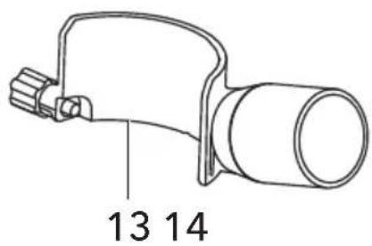

natural_image
Simple line drawing of a mechanical component with a cylindrical body and two protruding rods (no text or symbols)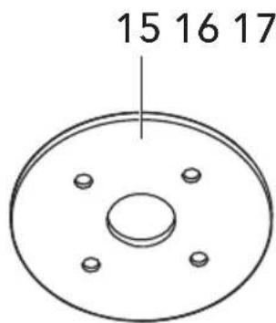
natural_image
Simple line drawing of a wrench with a vertical line above it (no text or symbols)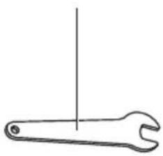
natural_image
Simple line drawing of a wrench with a vertical line above it (no text or symbols)

natural_image
Technical diagram of a mechanical assembly with no visible text or symbols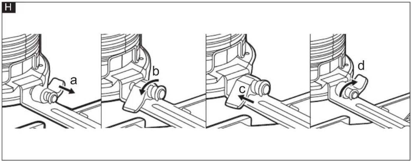
natural_image
Technical line drawing of a mechanical device with internal components and mounting base (no text or symbols)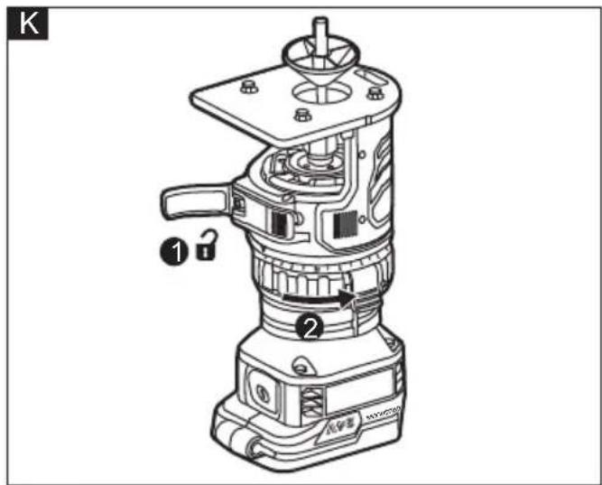
natural_image
Technical illustration of a mechanical assembly showing disassembled parts and exploded view (no text or symbols)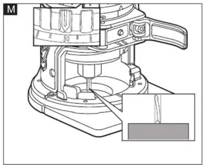
natural_image
Technical line drawing of a mechanical device with a close-up inset showing a tool interacting with a component (no text or symbols present)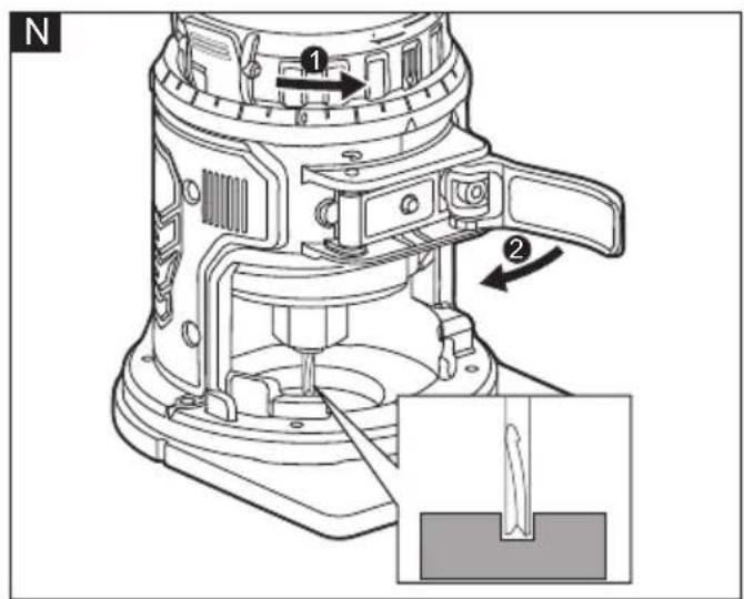
natural_image
Technical line drawing of a mechanical device labeled 'FLEX' with an inset showing internal components (no text or symbols beyond label)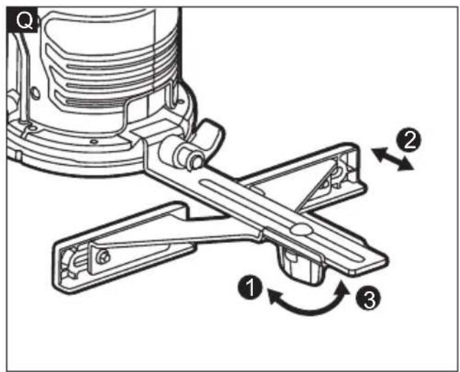
natural_image
Technical illustration of a mechanical device mounted on a workbench, showing motion lines and no text or symbols.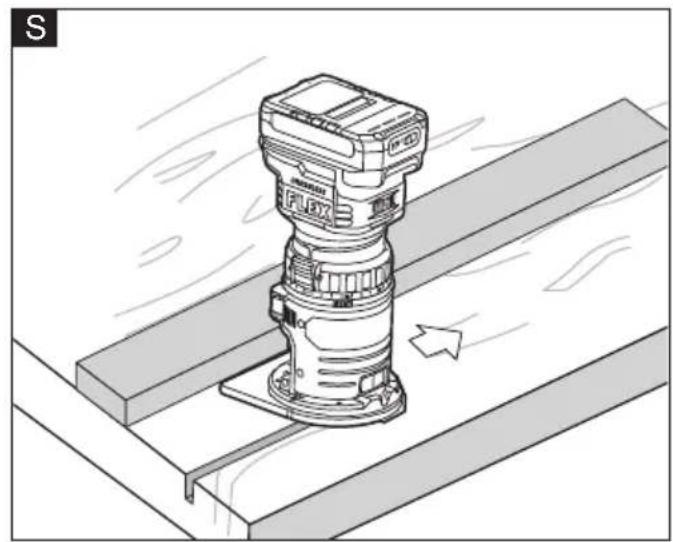
natural_image
Technical illustration of a mechanical assembly with a mounted component and directional arrow (no text or symbols)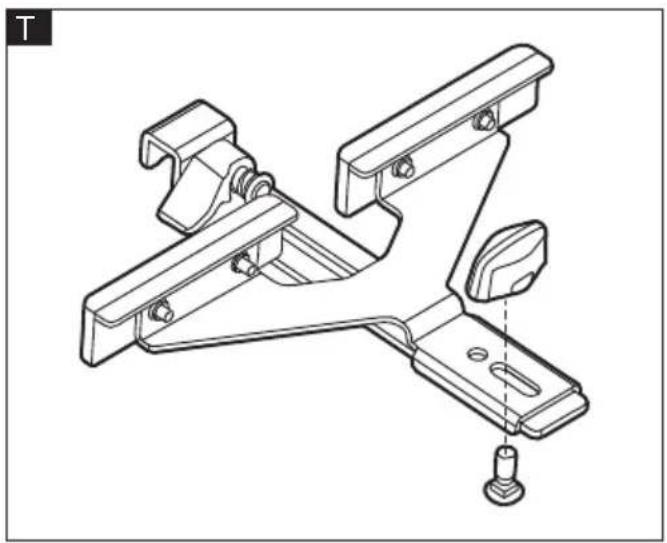
natural_image
Technical line drawing of a mechanical bracket assembly with mounting holes and a bolted base (no text or symbols)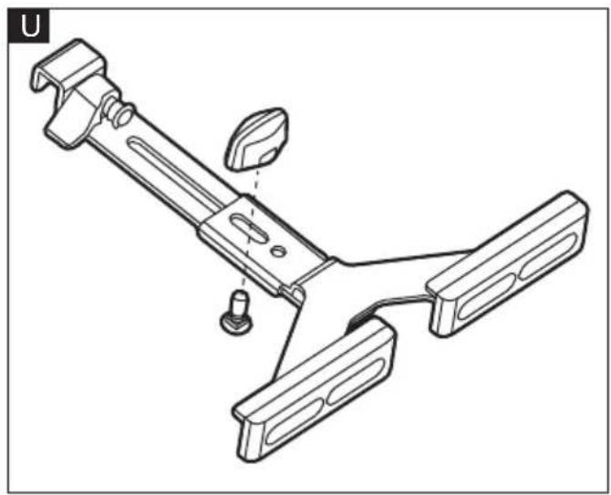
natural_image
Technical line drawing of a mechanical clamp or bracket assembly (no text or symbols)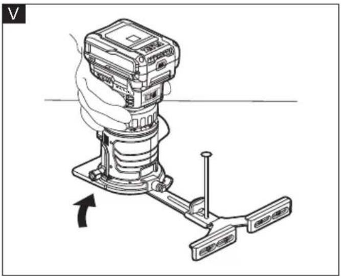
natural_image
Diagram of a mechanical device with a hand operating it, showing a lever mechanism (no text or symbols present)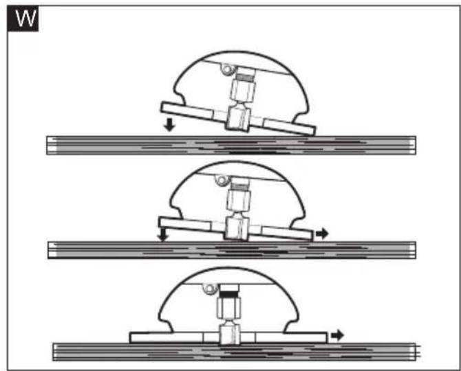
natural_image
Three sequential mechanical assembly diagrams showing a piston-cranked mechanism with downward force arrows, no text or symbols present.X
flowchart
graph TD
    A["Shaded Area"] --> B["Central Channel"]
    B --> C["Arrow 1: Downward flow"]
    B --> D["Arrow 2: Upward flow"]
    B --> E["Arrow 3: Leftward flow"]
    B --> F["Arrow 4: Rightward flow"]
Symbols used in this manual

WARNING!
Denotes impending danger. Non-observance of this warning may result in death or extremely severe injuries.

CAUTION!
Denotes a possibly dangerous situation. Non-observance of this warning may result in slight injury or damage to property.

NOTE
Denotes application tips and important information.
Symbols on the power tool
V Volts
/min Rotation rate

Wear Eye Protection

Wear Ear Protection

Read the instructions

Disposal information for the old machine
Important safety information

WARNING!
Before using the power tool, please read the follow:
– these operating instructions,
- the "General safety instructions" on the handling of power tools in the enclosed booklet (leaflet-no.: 315.915),
– the currently valid site rules and the regulations for the prevention of accidents.
This power tool is state of the art and has been constructed in accordance with the acknowledged safety regulations. Nevertheless, when in use, the power tool may
be a danger to life and limb of the user or a third party, or the power tool or other property may be damaged.
The trim router may be operated only if it is
- for its intended use
– in perfect working order.
Faults which impair safety must be repaired immediately.
Intended use
The rechargeable trim router CER 18-EC is designed
– for commercial use in industry and trade,
- for straight and grooved milling and the forming of edges in wood or similar materials,
- for dust free routing when used in combination with a suitable vacuum cleaner/dust exactor.
Safety instructions for trim router WARNING!
Read all safety warnings, instructions, illustrations and specifications provided with this power tool. Failure to follow all instructions listed below may result in electric shock, fire and/or serious injury. Save all warnings and instructions for future reference.
■ Use clamps or another practical way to secure and support the workpiece to a stable platform. Holding the work by your hand or against the body leaves it unstable and may lead to loss of control.
■ Never operate cutter bits at speeds that are higher than their maximum rated speed. Cutter bits running faster than their rated speed can break and fly apart.
■ Never use cutter bits with a diameter exceeding the maximum diameter specified in the technical data section.
Noise and vibration
The noise and vibration values have been determined in accordance with EN 62841. The A-weighted noise level of the power tool is typically:
– Sound pressure level L_pA : 79 dB(A);
- Sound power level L_WA : 87 dB(A);
- Uncertainty: K = 3 dB.
Total vibration value:
- Emission value a_h : <2.5 m/s
- Uncertainty: K = 1.5 m/s

CAUTION!
The indicated measurements refer to new power tools. Daily use causes the noise and vibration values to change.

NOTE
The vibration emission level given in this information sheet has been measured in accordance with a measurement method standardised in EN 62841 and may be used to compare one tool with another.
That the declared vibration total value(s) and the declared noise emission value(s) may also be used in a preliminary assessment of exposure.
However, if the tool is used for different applications, with different cutting accessories or poorly maintained, the vibration emission level may differ.
This may significantly increase the exposure level over the total working period.
To make an accurate estimation of the vibration exposure level, it is also necessary to take into account the times when the tool is switched off or running but not actually in use.
This may significantly decrease the exposure level over the total working period.
Identify additional safety measures to protect the operator from the effects of vibration such as: maintain the tool and the cutting accessories, keep the hands warm, organisation of work patterns.

WARNING!
- that the vibration and noise emissions during actual use of the power tool can differ from the declared values depending on the ways in which the tool is used especially what kind of workpiece is processed; and
- of the need to identify safety measures to protect the operator that are based on an estimation of exposure in the actual conditions of use(taking account of all parts of the operating cycle such as the times when the tool is switched off and when it is running idle in addition to the trigger time).

CAUTION!
Wear ear defenders at a sound pressure above 85 dB(A).
Technical data
| Tool CER 18-EC | |||
| Type Trim Router | |||
| Rated voltage Vdc 18 | |||
| Collet capacity mm | 6.35 | ||
| 8 | |||
| No-load speed /min | Up to 30000 | ||
| Weight according to "EPTA Procedure 01/2003" (without battery) | kg 1.6 | ||
| Battery AP 2.5 | AP 5.0 A | P 8.0 | |
| Weight of battery/kg | 0,42 0,72 | 1,18 | |
| Working Temperature | -10~40°C | ||
| Charging Temperature | 4~40°C | ||
| Storage Temperature | <50°C | ||
| Charger | CA 10.8/18.0, CA 18.0-LD | ||
Overview (see figure A)
The numbering of the product features refers to the illustration of the machine on the graphics page.
1 On/Off switch
2 Depth adjustment ring
3 Depth adjustment scale
4 Base lock lever
5 SPINDLE STOP™ Spindle lock
6 6.35 mm Collet
7 D-Shaped subbase
8 Quick release tab (x2)
9 Variable speed dial
10 Edge guide slot
11 LED lights
12 Edge guide assembly
13 Dust extraction hood
14 Centering cone
15 Round subbase
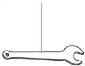
16 17mm Wrench
17 12mm Wrench
18 8 mm Collet
Instructions for use

WARNING!
Remove the battery before carrying out any work on the power tool.
Before switching on the power tool
Unpack the power tool and accessories and check that no parts are missing or damaged.

NOTE
The batteries are not fully charged on delivery. Prior to initial operation, charge the batteries fully. Refer to the charger operating manual.
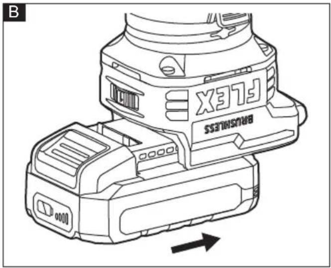
Inserting/replacing the battery
■ Press the charged battery into the power tool until it clicks into place (see figure B).
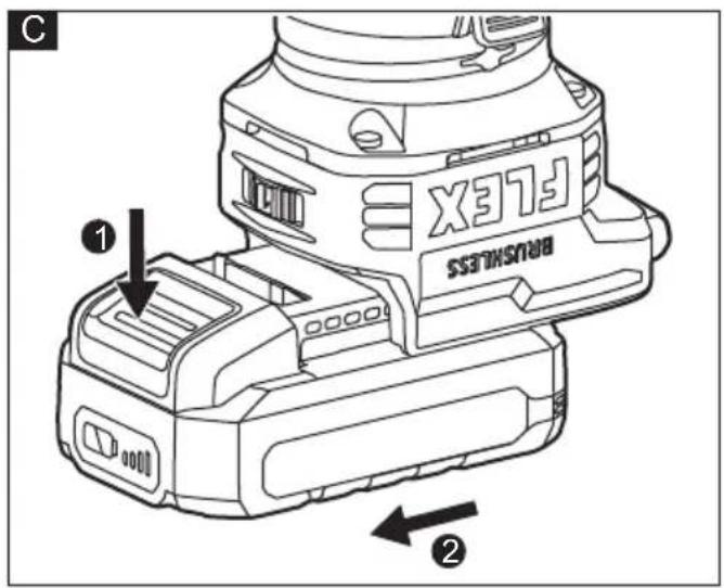
■ To remove, press the release button (1.) and pull out the battery (2.) (see figure C).

CAUTION!
When the device is not in use, protect the battery contacts. Loose metal parts may short circuit the contacts; explosion and fire hazard!
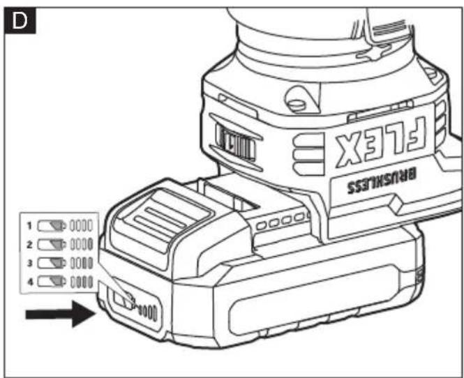
Battery state of charge
■ Press the button to check the state of charge at the state of charge indicator LEDs. (see figure D).
If one of the LEDs flashes, the battery must be recharged. If none of the LEDs light up after the button is pressed, the battery is faulty and must be replaced. The indicator goes out after 5 seconds.

NOTE
Follow the instructions for charging the battery set out in the charger operating manual.
Base quick release (see figure E)
a Open the lock lever
b Depress both quick release tabs and pull the base from the motor.
c To install the base, push the base unit down onto the unit until you hear a "click". Then close the lock lever. It is recommended to make the spindle lock face the dust outlet for easy operation.
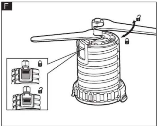
Installing/removing bits (see figure F)

WARNING!
Use protective gloves when removing the bit from the tool, or first allow the bit to cool down.
This router is shipped with a 6.35mm collet and a 8mm collet that accepts cutter bits with 6.35mm shanks and 8mm shanks, respectively.
a Remove the base
b Slide the spindle lock down or use the 12 mm wrench to hold the spindle securely.
c Use the 17 mm wrench to turn the collet nut counterclockwise.
d Install or remove the bit/collet as follows:
To install a bit, clean and insert the round shank of the desired router bit into the collet so that the cutting surfaces are approximately 3.2 mm to 6.4 mm away from the face of the collet.
To remove the bit, pull the bit out of the collet.
e Turn the collet nut clockwise to tighten the bit.
f Slide the spindle lock up.
g Install the base.

WARNING!
Tighten the collet nut securely to prevent the cutter bit from slipping. If the collet nut is not tightened securely, the cutter bit may detach during use, causing serious personal injury.

NOTE
To prevent damage to tool, do not tighten the collet nut without a cutter bit installed.

NOTE
To ensure proper gripping of the cutter bit shank and minimize run-out, the shank of the cutter bit must be inserted at least 16 mm into the collet.

NOTE
The tool could be started only when the spindle lock is released. The LED lights will flash to signal that the spindle is locked when the On/Off switch is pressed.
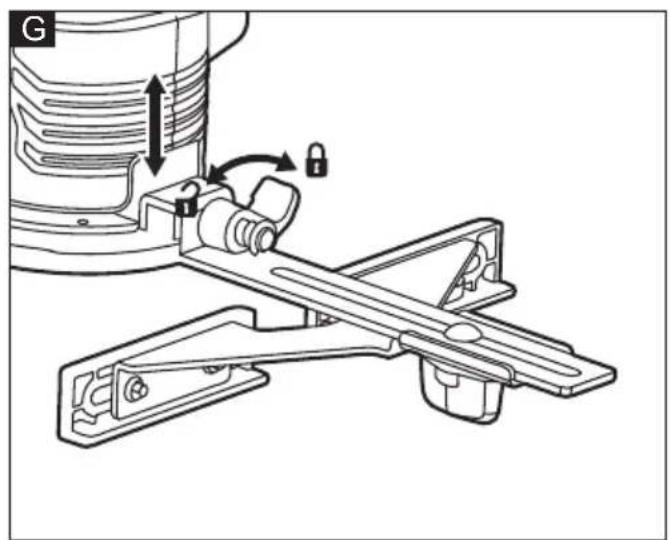
Installing/removing the edge guide assembly (see figure G)
a Turn the lock lever of the edge guide assembly to the left.
b Insert the hook of the edge guide assembly into the edge guide slot.
c Turn the lock lever to the right.
d To remove the edge guide assembly, turn the lock lever to the left and then remove it.
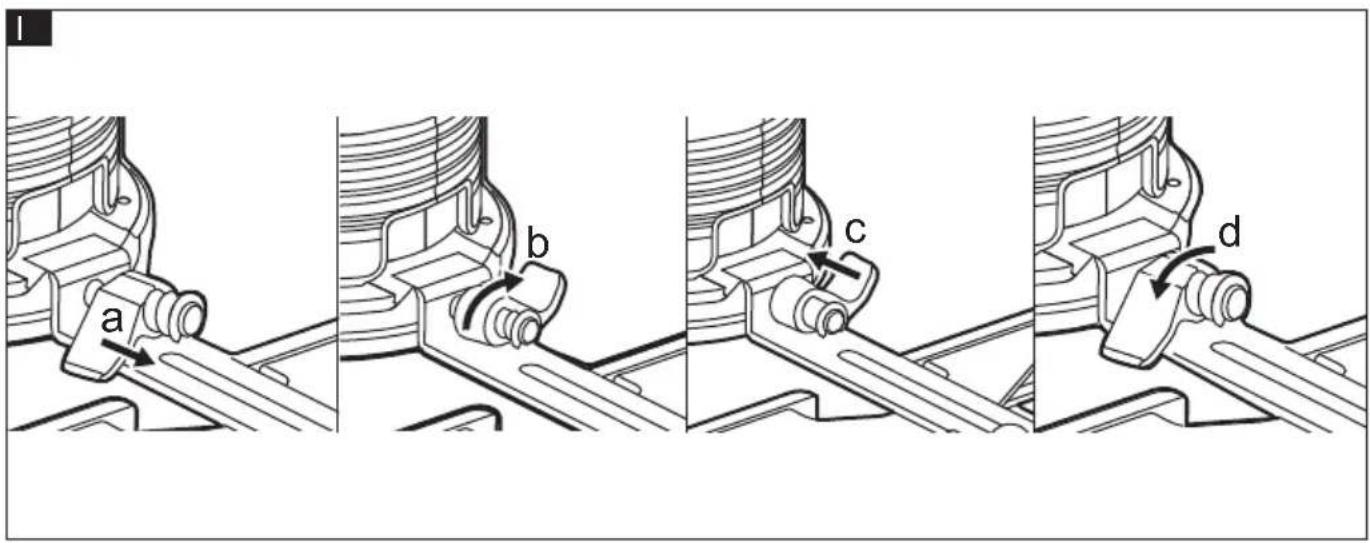
If the connection of edge guide assembly is loose, with the lock lever in the right-most position, pull the lock lever away from the hook and rotate it to the left. Then release the lock lever and turn it to the right (see figure H). If the edge guide assembly could not be removed easily, with the lock lever in the left-most position, pull the lock lever away from the hook and rotate it to the right. Then release the lock lever and turn it to the right (see figure I).
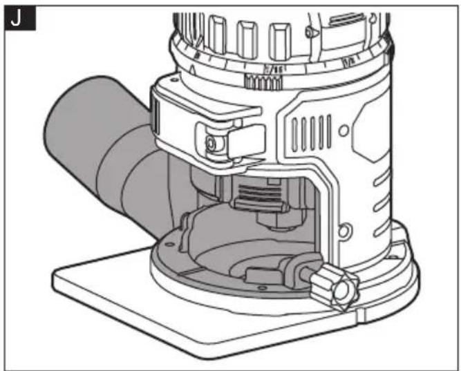
Installing/removing the dust extraction hood (see figure J)
The dust extraction hood allows connection of a 32 mm vacuum hose or adaptor.
a Insert the peg on the left side of the dust extraction hood into the slot on the left side of the base.
b Snap the right side of the hood with the screw knob onto the right side of the base.
c Tighten the screw knob.
d To remove the dust extraction hood, reverse the procedure.
Installing/removing the subbase (see figure K)
a Align the holes on the subbase with the holes at the bottom of the tool.
b Thread in but do not tighten the screws.
c Insert the pin of the centering cone into the collet and tighten the collet nut.
d Open the base lock lever and turn the depth adjustment ring until the centering cone stops and centers the subbase
e Close the base lock lever and tighten the screws.
f To remove the subbase, just loosen and remove the subbase screws.
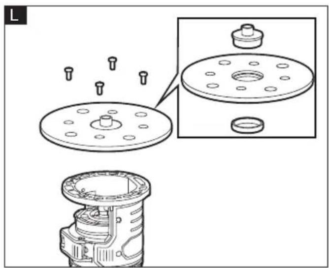
Template guides (not provided) (see figure L)
The round subbase will accept universal template guides. Use only a maximum 30.5 mm template guide with this tool.
The D-shaped subbase does not accommodate template guides and is designed to accommodate bits up to 38 mm in diameter.
a Center the round subbase.
b Insert the template guide into the center hole of the round subbase and secure according to the template guide instructions.
Adjusting the depth of cut (see figure M&N)
a Install the bit.
b Open the base lock lever.
c Turn the depth adjustment ring until the bit just touches the work piece.
d Turn the depth adjustment scale clockwise until the zero mark on the scale lines up with the pointer on the depth adjustment ring (see figure L).
e Turn the depth adjustment ring counterclockwise until the pointer lines up with desired depth of cut marking on the depth adjustment scale (see figure M). Each mark on the depth adjustment scale represents a depth change of 1/64" (0.4 mm) and one full (360°) turn of the ring changes the depth by 1/2" (12.7 mm).
f Close the base lock lever.
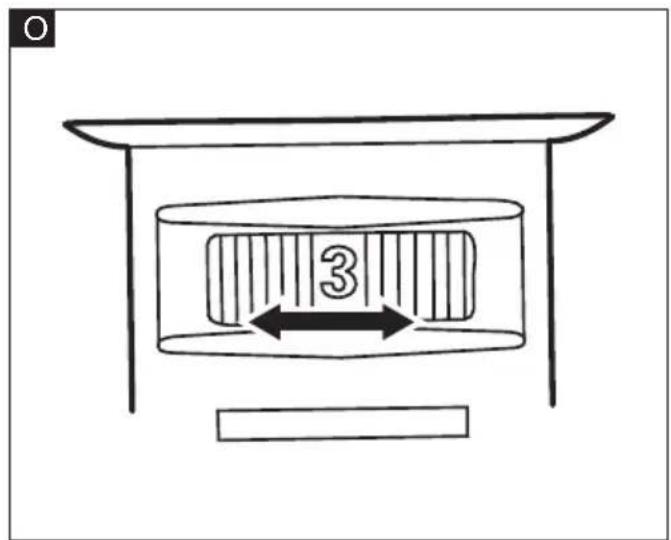
Variable speed dial (see figure O)
Turn the variable speed dial to control the router speed.
1-2 (Low Speed): 15000-17000 rpm
3-4 (Medium Speed): 20000-23000 rpm
5-6 (High Speed): 25000-30000 rpm
The speed dial is numbered "1" to "6", with position "1" being the lowest speed and position "6" being the highest speed.

WARNING!
Never change the speed while the tool is running. Failure to obey this could make you lose of control of the tool and result in serious personal injury and property damage.
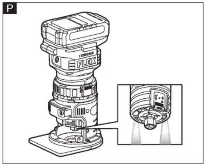
On/off switch (see figure P)
The soft-start feature minimizes torque twist, which is customary in router motors, by limiting the speed at which the motor starts. This increases the life of the motor.
To start the router, depress and release the on/off switch once.
To stop the router, depress and release the on/off switch again.
Always hold the tool and cutter bit away from the workpiece when turning on the switch. Only allow the tool and cutter bit to come into contact with the workpiece after it has reached full speed.
LED lights (see figure P)
■ The LED light will automatically turn on when starting the tool, and will turn off approximately 10 seconds after the tool is stopped.
■ The LED lights will flash to signal that the spindle lock is engaged when the On/Off switch is pressed. Release the spindle lock and start the tool again.
■ The LED lights will rapidly flash when the tool and/or battery pack becomes overloaded or too hot, and the internal sensors will turn the tool off. Rest the tool for a while or place the tool and battery pack separately under air flow to cool them.
■ The LED lights will flash more slowly to indicate that the battery is at low-battery capacity. Recharge the battery pack.
General operations

WARNING!
Removing the cutter bit from the workpiece while it is still rotating could damage the workpiece and result in loss of control, causing possibly serious personal injury.

WARNING!
Always clamp the workpiece securely and keep a firm grip on the tool base with both hands at all times. Failure to do so could result in loss of control, causing possibly serious personal injury. Making test cuts is essential with most routing applications. A test cut yields information about the set-up, the speed of the tool, the cutting depth, and how the cutter bit reacts to the workpiece. Much of routing is a trial-anderror process of making various adjustments, followed by test cuts, while learning all of the tool's operational abilities. To avoid ruining good material, make test cuts on scrap material. When operating the tool, always hold it firmly with both hands to maintain proper control.
Routing with the edge guide
The edge guide can be used as an aid in routing applications such as decorative edging, straight-edge planning and trimming, grooving, dadoing, and slotting.
Straight routing
a Loosen the knob and slide the fence along the arm of the edge guide to the desired length, then tighten the knob (see figure Q).
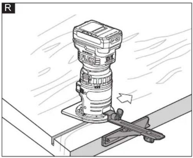
b Move the tool while keeping the edge guide flush with the side of the workpiece (see figure R).
Roundover bits with bearings are excellent for shaping the edge of any workpiece that is either straight or curved, if the curvature is at least as great as the radius of the bit to be used.
If the distance between the side of the workpiece and the cutting position is too wide for the edge guide, or if the side of the workpiece is not straight, firmly clamp a straight board to the workpiece and use it as a guide against the router base. Feed the tool in the direction of the arrow (see figure S).
Circular routing
The minimum and maximum radius of circles to be cut (distance between the center of circle and the center of bit) are 110 mm and 240 mm, respectively.
a Reassemble the knob and screw on the edge guide assembly as shown in Fig. T (smaller radius of cut) or Fig. U (larger radius of cut).
b Securely attach the edge guide to the base.
c Align the center hole in the edge guide with the center of the circle to be cut. Adjust the length of the edge guide.
d Drive a nail slightly less than 6.5 mm in diameter into the center hole to secure the edge guide.
e Pivot the tool clockwise around the nail to make the circle cut (Fig. V).
Internal routing (See figure W)
a With the cutting depth set, tilt the tool and place it on the workpiece, with only the leading edge of the subbase contacting the workpiece.
b Turn on the tool and allow it to reach its full speed, being careful not to allow the cutter bit to contact the workpiece.
c To begin the cut, gradually feed the cutter bit into the workpiece until the subbase is level with the workpiece, then move the router to make the cut.
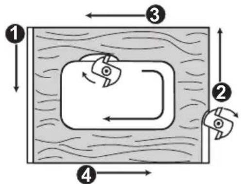
Feeding the trim router
■ Direction of feed (see figure X)
Feeding the tool in the opposite direction may cause loss of control, resulting in possibly personal injury.
■ Rate of Feed
The proper rate of feed depends on several factors: the hardness and moisture content of the workpiece, the cutting depth, and the cutting diameter of the bit. Use a faster rate of feed when cutting shallow grooves in soft woods, such as pine. Use a slower rate of feed when making deep cuts in hardwoods, such as oak.
Maintenance and care

WARNING!
Before performing any work on the power tool, remove the battery pack from the tool.
Cleaning

CAUTION!
When cleaning with compress air, always wear goggles.
Regularly clean the power tool and ventilation slots. Frequency of cleaning is dependent on the material and duration of use. Regularly blow out the housing interior and motor with dry compressed air.
Repairs
Repairs may be carried out by an authorized customer service centre only.
Spare parts and accessories
Other accessories, in particular tools and accessories, can be found in the manufacturer's catalogues. Exploded drawings and spare-part lists can be found on our homepage:
www.flex-tools.com.
Disposal information

WARNING!
Render redundant power tools unusable:
- battery operated power tool by removing the battery.

EU countries only
Do not throw electric power tools into the household waste!
In accordance with the European Directive 2012/19/EU on Waste Electrical and Electronic Equipment and transposition into national law used electric power tools must be collected separately and recycled in an environmentally friendly manner.

Raw material recovery instead of waste disposal.
Device, accessories and packaging should be recycled in an environmentally friendly manner. Plastic parts are identified for recycling according to material type.

WARNING!
Do not throw batteries into the household waste, fire or water. Do not open used batteries.
EU countries only:
In accordance with Directive 2006/66/EC defective or used batteries must be recycled.

NOTE
Please ask your dealer about disposal options!
CE-Declaration of conformity
We declare under our sole responsibility that the product described under "Technical specifications" conforms to the following standards or normative documents:
EN 62841 in accordance with the regulations of the directives 2014/30/EU, 2006/42/EG, 2011/65/EU.
Responsible for technical documents: FLEX-Elektrowerkzeuge GmbH, R & D Bahnhofstrasse 15, D-71711 Steinheim/Murr

Technical Director Head of Quality Department (QD)
UK CA Declaration of Conformity
We as the manufacturer: FLEX
declare under our sole responsibility, that the product(s) described under „Technical specifications“ fulfills all the relevant provisions of The Supply of Machinery
(Safety) Regulations S.I. 2008/1597 and also fulfills all the relevant provisions of the following UK Regulations:
Electromagnetic Compatibility Regulations
S.I. 2016/1091, The Restriction of the Use of Certain Hazardous Substances in Electrical and Electronic Equipment Regulations
S.I. 2012/3032 and are manufactured in accordance with the following designated Standards:
BS EN 62841-1:2015+A11:2022
BS EN 62841-2-17:2018
BS EN IEC 55014-1:2021
BS EN IEC 55014-2:2021
Place of declaration: Steinheim, Germany. Responsible person: Peter Lameli, Technical Director - FLEX-Elektrowerkzeuge GmbH
Contact details for Great Britain: FLEX Power Tools Limited, Unit 8 Anglo Office Park,
Lincoln Road, HP 12, 3RH Buckinghamshire, United Kingdom.

Technical Director Head of Quality
Department (QD)
06.12.2023
Exemption from liability
The manufacturer and his representative are not liable for any damage and lost profit due to interruption in business caused by the product or by an unusable product.
The manufacturer and his representative are not liable for any damage which was caused by improper use of the product or by use of the product with products from other manufacturers.
Voyants LED (voir figure P)
LED-lys (se figur P)
Base quick release (se figur E)
LED-lys (se figur P)
Technical Director Head of Quality
Department (QD)
- Negotovost: K = 3 dB.