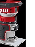
RFE 40 18.0-EC - Milling machine Flex - Free user manual and instructions
Find the device manual for free RFE 40 18.0-EC Flex in PDF.

| Product type | Milling machine for gutter bracket fixing |
| Brand | Flex |
| Model | RFE 40 18.0-EC |
| Battery voltage | 18 V |
| Compatible batteries | AP 18.0/2.5 Ah, AP 18.0/5.0 Ah |
| No-load speed (4 stages) | 1: 1-2800 rpm, 2: 1-3950 rpm, 3: 1-5100 rpm, 4: 1-6200 rpm |
| Mounting thread | M14 |
| Milling head diameter | 80 mm |
| Milling width | 40 mm |
| Milling depth | 6 mm or 8 mm (adjustable via support plate) |
| Weight (without battery) | 3.0 kg |
| Battery weight 2.5 Ah | 0.42 kg |
| Battery weight 5.0 Ah | 0.72 kg |
| Sound pressure level LPA | 82 dB(A) |
| Sound power level LWA | 93 dB(A) |
| Vibration (wood milling) | 2.8 m/s² (uncertainty K=1.5 m/s²) |
| Reversible blades | 4 blades, reusable by 90° rotation |
| Protection | Overload protection and temperature monitoring |
| Intended use | Professional, milling of wood and grooves for gutter bracket fixing |
| Maintenance and cleaning | Regularly clean ventilation slots and dust filter with dry compressed air |
| Repairs | Only by a service center authorized by the manufacturer |
| Spare parts | Exploded views and lists at www.flex-tools.com |
| Warranty | Do not loosen the gearbox screws under penalty of voiding warranty |
Frequently Asked Questions - RFE 40 18.0-EC Flex
User questions about RFE 40 18.0-EC Flex
0 question about this device. Answer the ones you know or ask your own.
Ask a new question about this device
Download the instructions for your Milling machine in PDF format for free! Find your manual RFE 40 18.0-EC - Flex and take your electronic device back in hand. On this page are published all the documents necessary for the use of your device. RFE 40 18.0-EC by Flex.
USER MANUAL RFE 40 18.0-EC Flex
natural_image
Illustration of a power tool with a blade and handle, no text or symbols presentde Originalbetriebsanleitung 3
en Original operating instructions 11
fr Notice d'instructions d'origine 19
it Istruzioni per l'uso originali 27
Inhalt
Verwendete Symbole 3
natural_image
Close-up of a mechanical component with a black arrow indicating a step, no visible text or symbolsnatural_image
Close-up of a microwave oven with a control panel and power button (no visible text or symbols)natural_image
Illustration of a hand using a power tool to clean or adjust equipment (no text or symbols visible)natural_image
Close-up of a car's front bumper with a curved arrow indicating motion (no text or symbols)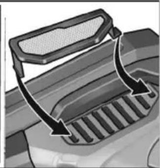
natural_image
Diagram of a vehicle's exhaust griddling with arrows indicating airflow direction (no text or symbols)Peter Lameli Technical Head
Klaus Peter Weinper Head of Quality Department (QD)
Symbols used in this manual ..... 11
Symbols on the power tool.... 11
Important safety information....11
Noise and vibration 12
Technical data 13
Overview 14
Instructions for use.... 15
Maintenance and care 17
Disposal information 18
C ∈ conformity.... 18
Exemption from liability 18
Symbols used in this manual

WARNING!
Denotes impending danger. Non-observance of this warning may result in death or extremely severe injuries.

CAUTION!
Denotes a potentially dangerous situation. Non-observance of this warning may result in injury or damage to property.

NOTE
Denotes hints on use and important information.
Symbols on the power tool

Read the operating instructions to mitigate the risk of injury.

Wear protective goggles.

Wear ear defenders.

Disposal information for the old tool (see page 18).
Important safety information

WARNING!
Before using the power tool, please read the following and act accordingly:
– these operating instructions,
- the "General safety instructions" on the handling of power tools in the enclosed booklet (leaflet no.: 315.915),
– the currently valid site rules and the regulations for the prevention of accidents.
This power tool is state of the art and has been constructed in accordance with the acknowledged safety regulations.
Nevertheless, when in use, the power tool may pose a danger to life and limb of the user or a third party, or the power tool or other property may be damaged. The power tool may be operated only
- for its intended use,
– in perfect working order.
Faults which compromise safety must be repaired immediately.
Intended use
The gutter bracket groove chaser RFE 40 18.0-EC is designed
-for commercial use in industry and trade, for chasing wood,
-for chasing mounting grooves for gutter brackets.
Safety instructions

WARNING!
Read all safety notices and instructions.
Failure to comply with the safety notices and instructions may result in electric shock, fire and/or serious injuries. Keep all safety notices and instructions in a safe place for future reference.
■ Wait until the blade shaft has come to rest before placing the power tool down. An exposed blade shaft could cut into the surface and cause loss of control as well as severe injuries.
■ Hold the power tool by the insulated handle surfaces only in case the blade shaft hits a live electrical cable. Contact with a live electrical cable could electrify metal parts of the power tool and cause an electric shock.
■ Hold and secure the workpiece using clamps or by other means to a steadfast surface or structure. If you only hold the workpiece by hand or against your body, it will be unstable and result in loss of control.
■ Do not reach into the chip ejection area. You could injure yourself on rotating parts.
■ Do not pass the chaser over metal objects, nails or screws. The blade and blade shaft could become damaged and cause increased vibrations.
■ When working, hold the power tool firmly with both hands and ensure that you have a secure footing. The power tool is controlled more securely when held with both hands.
■ Guide the power tool up to the workpiece only when the power tool is switched on. Otherwise there is the risk of kickback if the cutting accessory snags in the workpiece.
■ Protect yourself against hazardous dust. Dust from materials such as lead-based paint, some types of wood, minerals and metal can be hazardous to health. Contact with or inhalation of the dust can result in allergic reactions and/or breathing difficulties for the person using the tool or others in the vicinity. Some dusts such as from oak or beech are considered to be carcinogenic, particularly in connection with additives for wood treatment (chromate, wood preservative). Materials containing asbestos must be left to specialists.
- Where possible, use a dust extraction system suitable for the material.
- Ensure that the workplace is well ventilated.
– It is recommended to wear a respirator of filter class P2.
Observe the legislative requirements in your country for the materials that you are working with.

MATERIAL DAMAGE!
The mains voltage and the voltage specifications on the rating plate must correspond.
Noise and vibration

CAUTION!
The specified measured values refer to new power tools. Daily use causes the noise and vibration values to change.

NOTE
The vibration emission level given in this information sheet has been measured in accordance with a standardised test given in EN 62841 and may be used to compare one tool with another. It may be used for a preliminary assessment of exposure. The declared vibration emission level represents the main applications of the tool.
However, if the tool is used for different applications, with different cutting accessories or poor maintenance, the vibration emission level may differ. This may significantly increase the exposure level over the total working period.
To make an accurate estimation of the vibration exposure level, it is also necessary to take into account the times when the tool is switched off or running but not actually in use. This may significantly decrease the exposure level over the total working period.
Identify additional safety measures to protect the operator from the effects of vibration such as: tool and accessory maintenance, keep hands warm, standard operating procedures.

CAUTION!
Wear ear defenders at a sound pressure above 85 dB(A).
Technical data
| Device RFE 40 18.0-EC | ||
| Type Gutter bracket groove chaser | ||
| Mains voltage V 18 | ||
| Battery Ah AP 18.0/2.5 | AP 18.0/5.0 | |
| No load speed | rpm | 1 - 28002 - 39503 - 51004 - 6200 |
| Tool holder mm M14 | ||
| Blade head diameter mm 80 | ||
| Chasing width mm 40 | ||
| Chasing depth mm 6/8 | ||
| Weight according to "EPTA procedure 1/2003" | ||
| Weight (without battery) kg 3.9 | ||
| Weight of batteryAP 18.0/2.5AP 18.0/5.0 | kgkg | 0.420.72 |
| A-rated noise level in accordance with EN 62841 (see "Noise and vibration") | ||
| Sound pressure level L_PA | dB(A) | 82 |
| Sound power level L_WA | dB(A) | 93 |
| Uncertainty K | dB 3 | |
| Vibration total value in accordance with EN 62841 (see "Noise and vibration") | ||
| Emission value a_h when chasing wood | m/s^2 | 4.6 |
| Uncertainty K | m/s^2 | 1.5 |
Overview
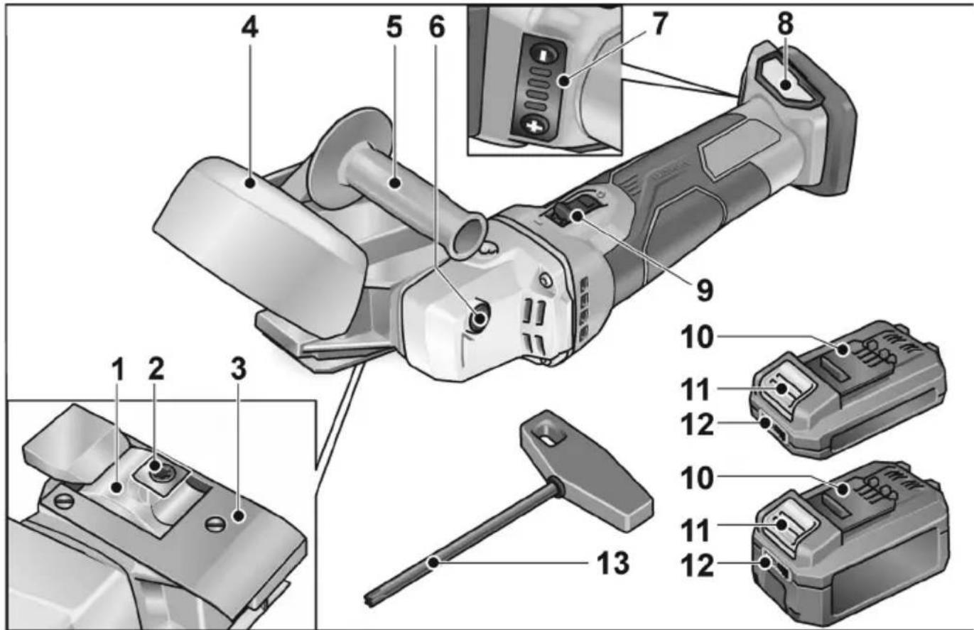
1 Chaser head
2 Reversible blade
3 Rest plate
4 Chip guide
5 Handle
6 Spindle lock
For holding the spindle during tool change.
7 Speed preselection
8 Slot for battery
9 Rocker switch
For switching on and off.
10 Li-ion battery (2.5 Ah or 5.0 Ah)
11 Release button for battery
12 State of charge indicator
13 Torx screwdriver
Instructions for use

WARNING!
Before carrying out any work on the power tool, remove the battery.
Before initial operation
Unpack the power tool and accessories and check that no parts are missing or were damaged during transport.

NOTE
The batteries are not fully charged on delivery. Charge the batteries fully before using for the first time. Consult the charger operating manual for this purpose.
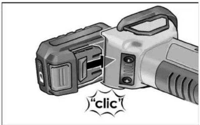
Inserting/replacing the battery
■ Press the charged battery into the power tool until it clicks into place.
■ To remove, press the release button (1.) and pull out the battery (2.).
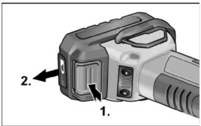

CAUTION!
Protect the battery contacts when the battery is not being used. Loose metal parts may short-circuit the contacts - explosion and fire hazard!
Battery state of charge
■ Press the button to check the state of charge on the state of charge indicator LEDs.
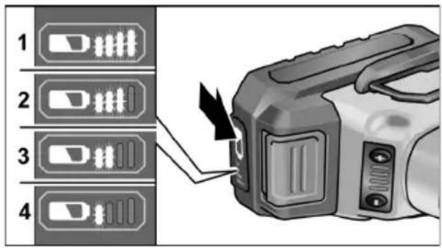
The indicator goes out after 5 seconds. If one of the LEDs flashes, the battery must be recharged. If none of the LEDs light up after the button is pressed, the battery is faulty and must be replaced.
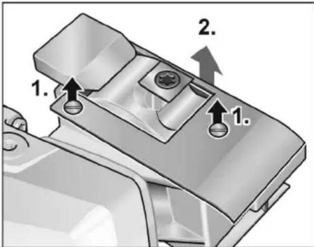
Inserting and changing the reversible blade

CAUTION!
Do not hold the reversible blade by the edges. Danger of flesh wounds!
The chaser head has 4 reversible blades. The reversible blades can be turned over.
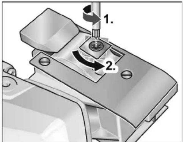
■ Rotate the chaser head until one of the reversible blades appears in the opening.
■ Use the Torx screwdriver to loosen the screw securing the reversible blade (1.).
■ Turn the reversible blade 90° until an unused side of the blade is aligned in the chaser (2.).
■ If all sides of the reversible blade are already worn, insert a new reversible blade.
■ Perform the same procedure for all 4 reversible blades.
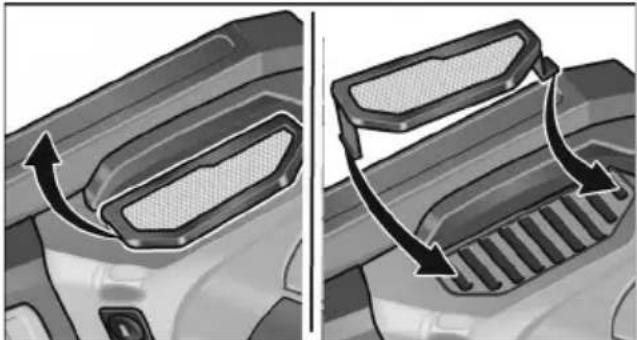
Adjusting the chasing depth
A chasing depth of between 6 mm to 8 mm can be selected.
Adjustment of the chasing depth is carried out by removal and assembly of the rest plate.
■ Using a screwdriver, loosen the screws securing the rest plate by turning in anticlockwise direction (1.).
■ Remove the rest plate (2.).
The chasing depth is now 8 mm.
If a chasing depth of 6 mm is required, reinstall the rest plate.
Switching the power tool on/off
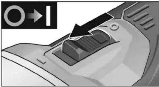
natural_image
Close-up of a mechanical component with a black arrow indicating direction, no visible text or symbols■ Push the switch rocker forwards and hold in position.
■ To switch off the power tool, release the switch rocker.
i NOTE
The switch rocker cannot be engaged because of safety reasons.
CAUTION!
The chaser head continues to run after switching off.
Speed preselection
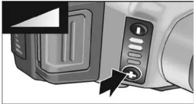
natural_image
Close-up of a microwave oven with control panel and buttons, showing a close-up of the door (no text or symbols visible)-To set the operating speed, press the speed regulation button. The speed selection remains set even after switching off.
-Press the switch carefully to accelerate the power tool to the preselected speed.
CAUTION!
Risk of injury from disintegration of the tool. Use a tool appropriate for the task at hand.
i NOTE
- Overload protection: Switches the machine off in the event of overload.
- Temperature monitoring: The machine will switch off if there is a risk of overheating.
Working with the power tool
WARNING!
The chaser head must not come into contact with sharp, protruding items. Risk of kickback! Damage to chaser head. If the reversible blades are damaged or heavily worn, they must be replaced without fail.
CAUTION!
Always hold the power tool firmly with both hands!
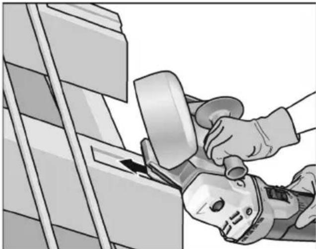
natural_image
Illustration of a hand using a power tool to clean or wear a component, no text or symbols visible- Secure the reversible blades and check that they are seated firmly.
- Check the chasing depth, adjust if necessary.
- Switch on the power tool.
- Bring the gutter bracket chaser into position on the working surface. The rest plate must be flush with the working surface.
- Guide the chaser over the material with even pressure.
Only use batteries and battery chargers of the manufacturer.
The order numbers are on our homepage: www.flex-tools.com
■ Do not use damaged batteries. These should be replaced straightaway.
■ Do not remove the battery.
■ Permissible ambient temperature (power tool, battery charger, battery)
- During charging 4 ... +40 °C
– During operation -20 ... +50 °C
- In storage -20 ... +50 °C
Maintenance and care

WARNING!
Remove the battery before carrying out any work on the power tool.
Cleaning

WARNING!
Do not use water or liquid detergents.
■ Regularly clean the power tool and ventilation slots.
■ Regularly blow out the housing interior and motor with dry compressed air.
■ Clean the dust filter at regular intervals.
natural_image
Two-panel illustration showing a car's front and side views of a helmet or seat cover, with arrows indicating the direction of change (no text or symbols present)■ Remove the dust filter and blow out with dry compressed air.
Gears

NOTE
Do not loosen the screws on the gear head during the warranty period. Failure to comply with this requirement will invalidate any claims under the manufacturer's warranty.
Repairs
Repairs may only be carried out by an authorised customer service centre.
Spare parts and accessories
Other accessories, in particular cutting accessories, can be found in the manufacturer's catalogues.
Exploded drawings and spare part lists can be found on our homepage:
www.flex-tools.com
Disposal information

WARNING!
End-of-life power tools must be rendered inoperable before disposal.
- For mains-operated power tools, remove the mains cable.
- For battery-operated power tools, remove the battery.

EU countries only
Do not dispose of electric power tools in household waste!
In accordance with the European Directive 2012/19/EU on Waste Electrical and Electronic Equipment and its incorporation into national law, used electric power tools must be collected separately and recycled in an environmentally-friendly manner.

Recycling raw materials instead of waste disposal.
Device, accessories and packaging should be recycled in an environmentally-friendly manner.
Plastic parts are identified for recycling according to material type.

WARNING!
Do not throw batteries into the household waste, fire or water. Do not open end-of-life batteries.
EU countries only: defective or end-of-life batteries must be recycled in accordance with Directive 2006/66/EC.

NOTE
Please ask your dealer about disposal options.
CE conformity
We declare on our sole responsibility that the product described under “Technical data” conforms to the following standards or normative documents:
EN 62841 according to the provisions of directives 2014/30/EU, 2006/42/EC, 2011/65/EC.
Responsible for technical documents: FLEX-Elektrowerkzeuge GmbH, R & D Bahnhofstrasse 15, D-71711 Steinheim/Murr
Peter Lameli Technical Head
Klaus Peter Weinper Head of Quality Department (QD)
15.12.2020
Exemption from liability
The manufacturer and his agent are not liable for any damage and lost profit due to interruption in business caused by the product or by an unusable product.
The manufacturer and his agent are not liable for any damage which was caused by improper use of the power tool or by use of the power tool with products from other manufacturers.
Table des matières
natural_image
Close-up of a mechanical component with a black arrow indicating direction (no text or symbols visible)natural_image
Close-up of a microwave oven with a control panel and power button (no visible text or symbols)natural_image
Illustration of a robotic hand using a power tool to clean or adjust equipment (no text or symbols visible)natural_image
Close-up of a car's front bumper with a curved arrow indicating direction (no text or symbols)
natural_image
Mechanical component with curved arrows indicating motion or force direction (no text or symbols)
Peter Lameli
Technical Head

Klaus Peter Weinper Head of Quality Department (QD)
15.12.2020
natural_image
Close-up of a mechanical component with a black arrow indicating direction, no visible text or symbolsnatural_image
Close-up of a microwave oven with control panel and buttons, showing a black arrow pointing to the button (no text or symbols visible)natural_image
Illustration of a hand using a power tool to clean or adjust equipment from a wall (no text or symbols visible)natural_image
Close-up of a car's front bumper with a curved arrow indicating motion (no text or symbols)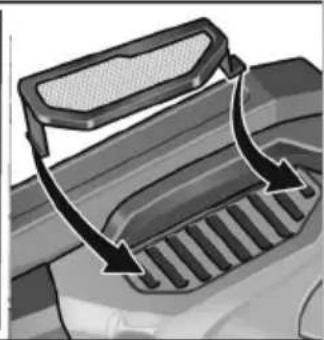
natural_image
Mechanical component with curved arrows indicating motion or force direction (no text or symbols)Peter Lameli Technical Head
Klaus Peter Weinper Head of Quality Department (QD)
15.12.2020