
GLT 35 18-EC - Grass trimmer Flex - Free user manual and instructions
Find the device manual for free GLT 35 18-EC Flex in PDF.

| Brand | Flex |
| Model | GLT 35 18-EC |
| Product type | Cordless grass trimmer |
| Usage category | Commercial use (industry and trade) |
| Rated voltage | 18 V (DC) |
| Weight of motor unit (without battery) | 2.7 kg |
| Weight of edger attachment | 1.7 kg (according to EPTA 01/2003) |
| Cutting mechanism | Bump head with twisted nylon line |
| Cutting line diameter | 2.4 mm |
| Length of supplied cutting line | 4 m |
| Cutting width | 35 cm |
| No-load speed | 5500-6500 rpm |
| Operating temperature | -10 °C to 40 °C |
| Charging temperature | 4 °C to 40 °C |
| Storage temperature | Below 50 °C |
| Compatible batteries | AP 18.0/2.5, AP 18.0/5.0, AP 18.0/8.0 |
| Compatible chargers | CA 10.8/18.0, CA 18.0-LD |
| Sound pressure level (L_PA) | 82.4 dB(A) (uncertainty K=2.22 dB) |
| Sound power level (L_WA) | 91.2 dB(A) (uncertainty K=2.22 dB) |
| Vibration emission value (a) | 7.28 m/s² (uncertainty K=1.5 m/s²) |
| Safety functions | Lock button, variable speed trigger, protective guard, emergency stop by releasing the trigger |
| Handles | Rear handle with trigger and adjustable front auxiliary handle |
| Speeds | 2 speeds: slow (position 1) and fast (position 2) |
| Maintenance | Cleaning with compressed air, gear lubrication every 50 h |
| Spare parts and repairability | Exploded views and lists on www.flex-tools.com, repairs by authorized service center |
Frequently Asked Questions - GLT 35 18-EC Flex
User questions about GLT 35 18-EC Flex
0 question about this device. Answer the ones you know or ask your own.
Ask a new question about this device
Download the instructions for your Grass trimmer in PDF format for free! Find your manual GLT 35 18-EC - Flex and take your electronic device back in hand. On this page are published all the documents necessary for the use of your device. GLT 35 18-EC by Flex.
USER MANUAL GLT 35 18-EC Flex
natural_image
Line drawing of a precision optical instrument with a circular head and hexagonal base (no text or symbols)en Original operating instructions....11
natural_image
Mechanical assembly diagram showing a rotating wheel and connecting rod with directional arrows indicating motion (no text or symbols)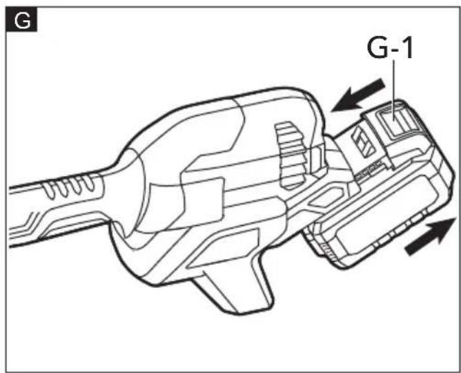

natural_image
Illustration of a person in protective gear using a long-handled manual shaver to spray plants (no text or symbols)In accordance with the European
Symbols used in this manual

WARNING!
Denotes impending danger. Non-observance of this warning may result in death or extremely severe injuries.

CAUTION!
Denotes a possibly dangerous situation. Non-observance of this warning may result in slight injury or damage to property.

NOTE
Denotes application tips and important information.
Symbols on the power tool
V
Volts

Read the instructions!

Disposal information for the old machine
For your safety

WARNING!
Before using the power tool, please read the follow:
– these operating instructions,
- the "General safety instructions" on the handling of power tools in the enclosed booklet (leaflet-no.: 315.915),
– the currently valid site rules and the regulations for the prevention of accidents.
This power tool is state of the art and has been constructed in accordance with the acknowledged safety regulations.
Nevertheless, when in use, the power tool may be a danger to life and limb of the user or a third party, or the power tool or other property may be damaged.
The power head may be used only
-asintended,
– in perfect working order.
Faults that impair safety must be repaired immediately.
Intended use
The power head is intended
– for commercial use in industry and trade,
- for using with only the following FLEX attachments Line Trimmer GLT 35 or subsequently introduced by FLEX.
Technical data
| Tool GPH 18-EC | |||
| Type Power Head | |||
| Voltage Vdc 18V | |||
| Weight (without battery back) | kg 2.7 | ||
| Battery 18V | AP 18.0/2.5AP 18.0/5.0AP 18.0/8.0 | ||
| Weight of battery | kg | AP 18.0/2.5AP 18.0/5.0AP 18.0/8.0 | 0.40.71.1 |
| Working Temperature | -10~40°C | ||
| Charging Temperature | 4~40°C | ||
| Storage Temperature | <50°C | ||
| Charger | CA 10.8/18.0, CA 18.0-LD | ||
Overview (see figure A)
The numbering of the product features refers to the illustration of the machine on the graphics page.
- Wing knob
- Coupler
- Shoulder-strap loop
- Speed mode switch
- Lock-off button
- Variable-speed trigger switch
- Rear handle
- Front-assist handle
- Assist-handle lock-lever
- Screw knob
Preparation
Know your power head
Before attempting to use the power head, familiarize yourself with all of its operating features and safety requirements.

WARNING!
Do not allow familiarity with the tool to cause carelessness. Remember that one careless moment is enough to cause severe injury. Before attempting to use any tool, be sure to become familiar with all of the operating features and safety instructions.

WARNING!
Do not attempt to modify this tool or create accessories not recommended for use with this tool. Any such alteration or modification is misuse and could result in a hazardous condition leading to possible serious personal injury.
Assembly

WARNING!
Read and understand the entire Operator's Manual for each optional attachment used with this power head and follow all warnings and instructions. Failure to follow all instructions could result in electric shock, fire and/or serious personal injury.

WARNING!
This 18V power head is designed to be used only with the attachment models that are specified in this Operator's Manual. Use of other, unauthorized attachments could cause serious personal injuries or property damage.

WARNING!
Some accessories have specific requirements related to safety. Always pay special attention to such instructions in the manual that accompanies each accessory.

WARNING!
Never install, remove, or adjust any attachment while the power head is running or with the battery installed. Failure to stop the motor and remove the battery can cause serious personal injury. NEVER OPERATE THE POWER HEAD WITHOUT AN ATTACHMENT.

WARNING!
Always remove the battery pack from the product when you are assembling parts, making adjustments, cleaning, or when the product is not in use.
Installing/removing the power head attachment
To install the attachment
a) Stop the motor and remove the battery pack.
b) Loosen the wing knob (1) (see Fig B).
c) The power head has two grooves on the coupler (2), ONLY the groove( B-2) is used to connect attachment: GLT 35.
d) Align the spring-loaded pin (C-2) on the attachment with the groove (C-1) on the coupler (2) and push the attachment shaft into the power head shaft until the pin pops out of the groove and you hear an audible "click" sound at the same time (see Fig C).
e) Pull the shaft of the attachment to verify that it is securely locked into the coupler (2).
f) Tighten the wing knob (1) securely.
To remove the attachment (See Fig D)
a) Stop the motor and remove the battery pack.
b) Loosen the wing knob.
c) Press down the spring-loaded pin (D-1), with the pin pressed, pull or twist the attachment shaft out of the coupler.
Mounting / adjusting the front-assist handle
To mount the front-assist handle (see Fig E)
a) Stop the motor and remove the battery pack from the power head.
b) Remove the screw knob (10) and the lock lever (9) from the front-assist handle (8).
c) Mount the front-assist handle (8) on the shaft.
d) Insert the lock lever (9) into the front-assist handle (8), and then tighten the screw knob (10). Make sure that the front-assist handle (8) faces upwards so that it points toward the rear handle.
e) Lower the lock lever to secure the front-assist handle onto the shaft so that it cannot move on the shaft during operation.
To adjust the front-assist handle position (see Fig F)
The handle should be adjusted so that the arm holding the front-assist handle is straight when using the power head.
To adjust the front-assist handle position, lift the lock lever so that the front-assistant handle can be moved to the desired position along the shaft. Lower the lock lever so that the handle cannot move on the shaft during operation.

WARNING!
There is a tag on the power head shaft to limit the adjustment distance of the front-assist handle to meet the requirements of the front and rear handle distance. Never adjust the front-assist handle beyond the tag position.

WARNING!
Never operate the tool without the front-assist handle firmly in place.
Attaching/removing the battery pack (see Fig G)

NOTE
Fully charge the battery pack before first use.
To attach
a) Align the raised portion on the battery pack with the grooves in the power head housing, then slide the battery pack onto the tool.
b) Make sure that the latches on the battery pack snap into place and the battery pack is secured to the tool before operation.

NOTE
When placing the battery pack on the tool, be sure that the raised rib on the battery pack aligns with the groove on the tool and the latches snap into place properly. Improper assembly of the battery pack can cause damage to internal components.
To remove
■ Press the battery-release button (G-1) and pull the battery pack out.

WARNING!
Battery tools are always in operating condition. Therefore, to avoid serious personal injury, always remove the battery pack and keep your hands clear of the lock-off button and variable speed trigger switch when carrying or transporting the tool.
Operating
Starting/stopping the power head (see Fig H)

WARNING!
Never operate the power head without an attachment. Do not attempt to start the power head without an attachment.
To start the power head
a) To turn the power head ON, push the lock-off button (5) to left or right and then depress the variable-speed trigger switch (6).
b) The variable-speed trigger switch (6) delivers higher speed with increased trigger pressure and lower speed with decreased trigger pressure.
To stop the power head
Release the variable-speed trigger switch (6) to stop the power head.

WARNING!
Always remove the battery pack from the power head during work breaks and after finishing work.
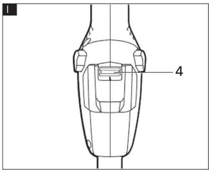
Changing speed mode (see Fig I)
Slide the speed-selector switch (4) to position "1" for low speed or position "2" for high speed.

NOTE
The runtime will decrease in high-speed mode compared to that in low-speed mode.
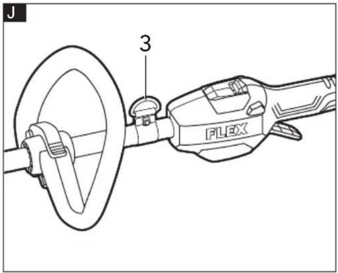
Using shoulder strap (sold separately)
For safe and comfortable operation, put the strap over one of your shoulders and across your back.
a) Remove the battery pack from the power head.
b) Depress the shoulder strap carabiner to open it and attach it into the shoulder-strap loop (3) (see Fig J).
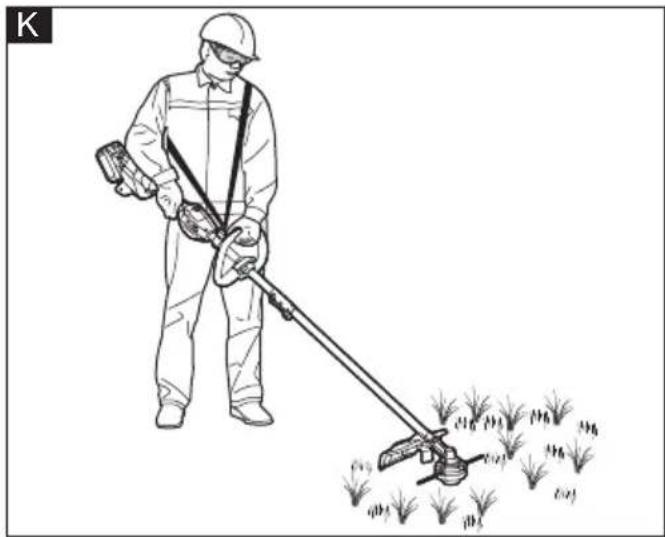
c) Adjust the shoulder strap length to a comfortable operating position - hold the trimmer with both hands: one hand on the rear handle and the other hand on the front-assist handle (see Fig K).

WARNING!
When an emergency occurs, take the shoulder strap off from your shoulder immediately, no matter what way the strap is on.
Maintenance and care

WARNING!
Before performing any work on the power tool, remove the battery pack from the tool.
Cleaning

CAUTION!
When cleaning with compressed air, always wear goggles.
Regularly clean the power tool and ventilation slots. Frequency of cleaning is dependent on the material and duration of use. Regularly blow out the housing interior and motor with dry compressed air.
Repairs
Repairs should only be carried out by an authorized customer service centre.
Spare parts and accessories
Other accessories, in particular tools and accessories, can be found in the manufacturer's catalogues. Exploded drawings and spare-part lists can be found on our homepage: www.flex-tools.com.
Disposal information

WARNING!
Render redundant power tools unusable:
- mains operated power tool by removing the power cord,
- battery operated power tool by removing the battery.

EU countries only
Do not throw electric power tools into the household waste!
In accordance with the European Directive 2012/19/EU on Waste Electrical and Electronic Equipment and transposition into national law used electric power tools must be collected separately and recycled in an environmentally friendly manner.

Raw material recovery instead of waste disposal.
Device, accessories and packaging should be recycled in an environmentally friendly manner. Plastic parts are identified for recycling according to material type.

WARNING!
Do not throw batteries into the household waste, fire or water. Do not open used batteries.
EU countries only: In accordance with Directive 2006/66/EC defective or used batteries must be recycled.

NOTE
Please ask your dealer about disposal options!
CE-Declaration of conformity
We declare under our sole responsibility that the product described under "Technical specifications" conforms to the following standards or normative documents:
EN 62841 in accordance with the regulations of the directives 2014/30/EU, 2006/42/EG, 2011/65/EU.
Responsible for technical documents:
Technical Director Head of Quality
Department (QD)
Declaration of Conformity
We as the manufacturer: FLEX Elektrowerkzeuge GmbH, Business address: Bahnhofstr. 15, 71711 Steinheim, Germany declare under our sole responsibility, that the product(s) described under „Technical specifications“ fulfills all the relevant provisions of The Supply of Machinery (Safety) Regulations S.I. 2008/1597 and also fulfills all the relevant provisions of the following UK Regulations:
Electromagnetic Compatibility Regulations S.I. 2016/1091, The Restriction of the Use of Certain Hazardous Substances in Electrical and Electronic Equipment Regulations
S.I. 2012/3032 and are manufactured in accordance with the following designated Standards:
BS EN 62841-1:2015
BS EN IEC 55014-1:2021
BS EN IEC 55014-2:2021
Place of declaration: Steinheim, Germany.
Responsible person: Peter Lameli, Technical Director - FLEX-Elektrowerkzeuge GmbH
Contact details for Great Britain: FLEX Power Tools Limited, Unit 8 Anglo Office Park, Lincoln Road, HP 12, 3RH Buckinghamshire, United Kingdom.

Peter Lameli Klaus Peter Weinper
Technical Director Head of Quality
Department (QD)
08.20.2023
Exemption from liability
The manufacturer and his representative are not liable for any damage and lost profit due to interruption in business caused by the product or by an unusable product. The manufacturer and his representative are not liable for any damage which was caused by improper use of the product or by use of the product with products from other manufacturers.
Peter Lameli Klaus Peter Weinper Technical Head Head of Quality
Department (QD)
natural_image
Line drawing of a long-handled tool or device with a lever and base mount (no text or symbols)en Original operating instructions....15
natural_image
Illustration of a worker using a long-handled tool to spread vegetation, with no text or symbols present.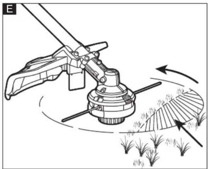
natural_image
Diagram of a manual sprinkler system with rotating blades and directional arrows indicating movement (no text or symbols)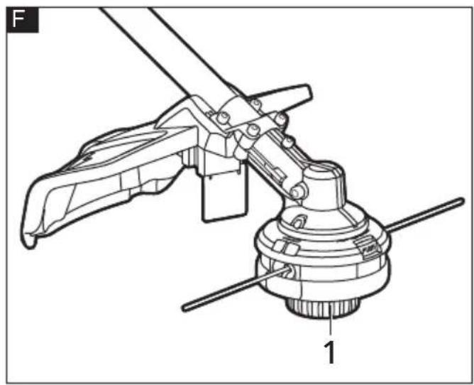
natural_image
Technical line drawing of a mechanical clamp or lever assembly (no text or symbols)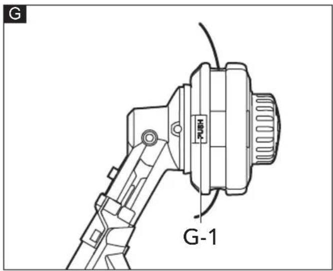

natural_image
Line drawing of a hand using a tool to adjust or install a mechanical component (no text or symbols present)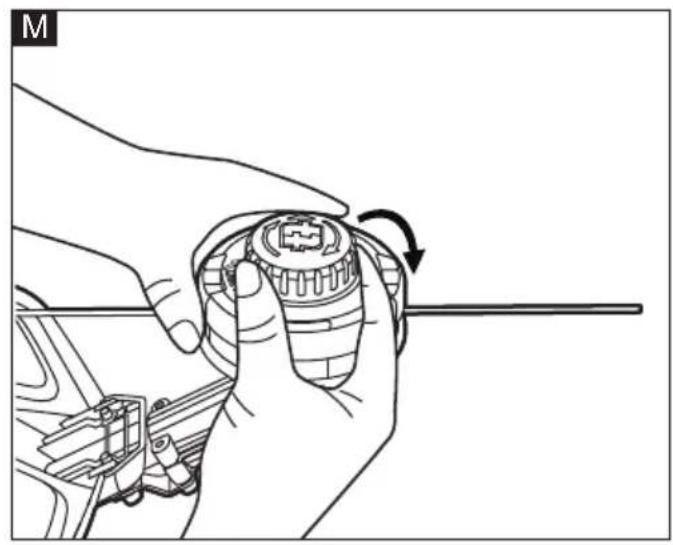
natural_image
Line drawing of a hand holding a mechanical component with a rotating arrow (no text or symbols)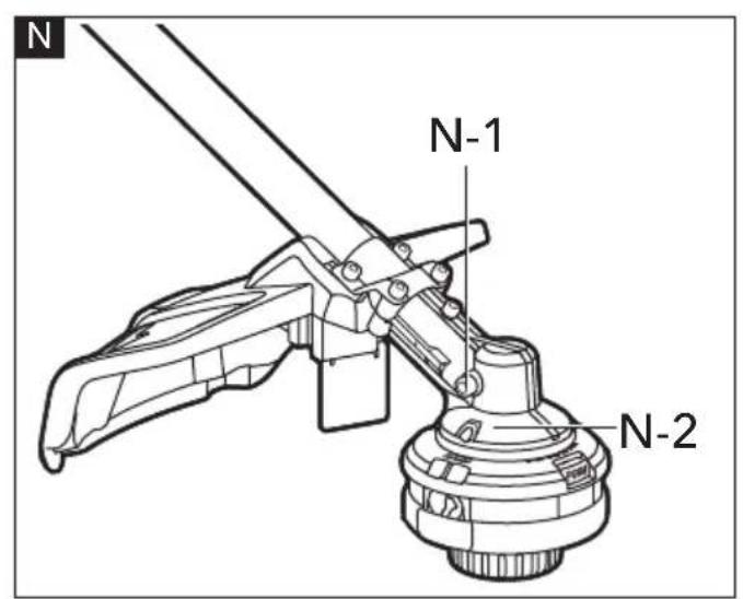
Symbols used in this manual

WARNING!
Denotes impending danger. Non-observance of this warning may result in death or extremely severe injuries.

CAUTION!
Denotes a possibly dangerous situation. Non-observance of this warning may result in slight injury or damage to property.

NOTE
Denotes application tips and important information.
Symbols on the power tool
V Volts
/min Rotationrate

Read the instructions

Wear ear protection

Wear eye protection

Do not use metal blades

WARNING - Beware of thrown objects

WARNING - Keep bystanders away

WARNING - The distance between the machine and bystanders shall be at least 15 m

WARNING - Disconnect battery before maintenance

Disposal information for the old machine (see page 21)!
For your safety

WARNING!
Before using the power tool, please read the follow:
– these operating instructions,
- the "General safety instructions" on the handling of power tools in the enclosed booklet (leaflet-no.: 315.915),
- the currently valid site rules and the regulations for the prevention of accidents.
This power tool is state of the art and has been constructed in accordance with the acknowledged safety regulations.
Nevertheless, when in use, the power tool may be a danger to life and limb of the user or a third party, or the power tool or other property may be damaged.
The line trimmer may be used only
-asintended,
- in perfect working order.
Faults that impair safety must be repaired immediately.
Intended use
The line trimmer is intended
– for commercial use in industry and trade,
- for trimming grass and weeds from around porches, fences, and decks with only the following FLEX Power Head GLT 35 18-EC or subsequently introduced by FLEX.
Safety instructions for line trimmer

WARNING!
Read all safety warnings, instructions, illustrations and specifications provided with this power tool. Failure to follow all instructions listed below may result in electric shock, fire and/or serious injury. Save all warnings and instructions for future reference.
■ Do not use the machine in bad weather conditions, especially when there is a risk of lightning. This decreases the risk of being struck by lightning.
■ Thoroughly inspect the area for wildlife where the machine is to be used. Wildlife may be injured by the machine during operation.
■ Thoroughly inspect the area where the machine is to be used and remove all stones, sticks, wires, bones, and other foreign objects. Thrown objects can cause personal injury.
■ Before using the machine, always visually inspect to see that the cutter or blade and the cutter or blade assembly are not damaged. Damaged parts increase the risk of injury.
■ Follow instructions for changing accessories. Improperly tightened blade securing nuts or bolts may either damage the blade or result in it becoming detached.
■ Wear eye, ear, head and hand protection. Adequate protective equipment will reduce personal injury by flying debris or accidental contact with the cutting line or blade.
■ While operating the machine, always wear non-slip and protective footwear. Do not operate the machine when barefoot or wearing open sandals. This reduces the chance of injury to the feet from contact with the moving cutters or lines.
■ While operating the machine, always wear long trousers. Exposed skin increases the likelihood of injury from thrown objects.
- Keep bystanders away while operating the machine. Thrown debris can result in serious personal injury.
■ Always use two hands when operating the machine. Holding the machine with both hands will avoid loss of control.
- Hold the machine by the insulated gripping surfaces only, because the cutting line or blade may contact hidden wiring. Cutting line or blades contacting a "live" wire may make exposed metal parts of the machine "live" and could give the operator an electric shock.
■ Always keep proper footing and operate the machine only when standing on the ground. Slippery or unstable surfaces may cause a loss of balance or control of the machine.
■ Do not operate the machine on excessively steep slopes. This reduces the risk of loss of control, slipping and falling which may result in personal injury.
■ When working on slopes, always be sure of your footing, always work across the face of slopes, never up or down and exercise extreme caution when changing direction. This reduces the risk of loss of control, slipping and falling which may result in personal injury.
- Keep all parts of the body away from the cutter, line or blade when the machine is operating. Before you start the machine, make sure the cutter, line or blade is not contacting anything. A moment of inattention while operating the machine may result in injury to yourself or others.
■ Do not operate the machine above waist height. This helps prevent unintended cutter or blade contact and enables better control of the machine in unexpected situations.
- When cutting brush or saplings that are under tension, be alert for spring back. When the tension in the wood fibres is released, the brush or sapling may strike the operator and/ or throw the machine out of control.
■ Use extreme caution when cutting brush and saplings. The slender material may catch the blade and be whipped toward you or pull you off balance.
■ Maintain control of the machine and do not touch cutters, lines or blades and other hazardous moving parts while they are still in motion. This reduces the risk of injury from moving parts.
- Carry the machine with the machine switched off and away from your body. Proper handling of the machine will reduce the likelihood of accidental contact with a moving cutter, line or blade.
■ Only use replacement cutters, lines, cutting heads and blades specified by the manufacturer. Incorrect replacement parts may increase the risk of breakage and injury.
■ When clearing jammed material or servicing the machine, make sure the switch is off and the battery pack is removed. Unexpected starting of the machine while clearing jammed material or servicing may result in serious personal injury.
- Carry the machine with the machine switched off and away from your body. Proper handling of the machine will reduce the likelihood of accidental contact with a moving cutter, line or blade.
■ Only use replacement cutters, lines, cutting heads and blades specified by the manufacturer. Incorrect replacement parts may increase the risk of breakage and injury.
■ Damage to Trimmer - If you strike a foreign object with the trimmer or it becomes entangled, stop the tool immediately, check for damage and have any damage repaired before further operation is attempted. Do not operate with a broken guard or spool.
If the equipment should start to vibrate abnormally, stop the motor and check immediately for the cause. Vibration is generally a warning of trouble. A loose head may vibrate, crack, break or come off the trimmer, which may result in serious or fatal injury. Make sure that the cutting attachment is properly fixed in position. If the head loosens after fixing it in position, replace it immediately. Never use a trimmer with a loose cutting attachment.t
■ Battery tools do not have to be plugged into an electrical outlet; therefore, they are always in operating condition. Be aware of possible hazards even when the tool is not operating. Take care when performing maintenance or service.
■ Do not wash with a hose; avoid getting water in motor and electrical connections.
Noise and vibration
The noise and vibration values have been determined in accordance with EN 62841.
The A-weighted noise level of the power tool is typically:
- Sound pressure level L_pA at operator's position: 82.4 dB(A);
- Sound power level L_WA : 91.2 dB(A);
- Uncertainty: K = 2.22 dB.
– Guaranteed sound power level: 96dB(A)
Total vibration value:
- Emission value a_h : 7.28 m/s
- Uncertainty: K = 1.5 m/s

CAUTION!
The indicated measurements refer to new power tools. Daily use causes the noise and vibration values to change.
NOTE
The vibration emission level given in this information sheet has been measured in accordance with a measurement method standardised in EN 62841 and may be used to compare one tool with another.
That the declared vibration total value(s) and the declared noise emission value(s) may also be used in a preliminary assessment of exposure.
However, if the tool is used for different applications, with different cutting accessories or poorly maintained, the vibration emission level may differ.
This may significantly increase the exposure level over the total working period.
To make an accurate estimation of the vibration exposure level, it is also necessary to take into account the times when the tool is switched off or running but not actually in use.
This may significantly decrease the exposure level over the total working period.
Identify additional safety measures to protect the operator from the effects of vibration such as: maintain the tool and the cutting accessories, keep the hands warm, organisation of work patterns.
WANNING:
- that the vibration and noise emissions during actual use of the power tool can differ from the declared values depending on the ways in which the tool is used especially what kind of workpiece is processed; and
- of the need to identify safety measures to protect the operator that are based on an estimation of exposure in the actual conditions of use(taking account of all parts of the operating cycle such as the times when the tool is switched off and when it is running idle in addition to the trigger time).
CAUTION!
Wear ear defenders at a sound pressure above 85 dB(A).
Technical data
| Tool GLT 35 | ||
| Type Line Trimmer | ||
| Cutting mechanism Bump head | ||
| No-load speed /min | 5500-6500 | |
| Cutting-line type | 4m Φ2.4mm twisted nylon line | |
| Cutting width cm 35 | ||
| Weight according to "EPTA Procedure 01/2003" | kg 1.7 | |
| Working temperature -10~ | 40°C | |
| Storage temperature <50°C | ||
Overview (see figure A)
The numbering of the product features refers to the illustration of the machine on the graphics page.
- Bump head
- Cutting line
- Trimmer head
- Trimmer attachment shaft
- Line-cutting blade
- Guard
- Hex key
- Bolt (2)
- Spring washer (2)
Preparation
Know your line trimmer
This product requires assembly. Carefully lift the tool from the carton and place it on a level work surface. Before attempting to use the line trimmer attachment, familiarize yourself with all of its operating features and safety requirements.

WARNING!
■ Do not allow familiarity with the tool to cause carelessness. Remember that one careless moment is enough to cause severe injury. Before attempting to use any tool, be sure to become familiar with all of the
operating features and safety instructions.
■ Do not attempt to modify this tool or create accessories not recommended for use with this tool. Any such alteration or modification is misuse and could result in a hazardous condition leading to possible serious personal injury.
Assembly

WARNING!
This product requires assembly. To reduce the risk of injury to persons, never operate without the guard in place. The guard must always be on the tool to protect the user.
Mounting the guard (See Fig B&C)
■ Install the guard before the attachment is connected to the power head.
■ To reduce the risk of injury to persons, do not operate without guard in place.
a. Loosen the two bolts (8) in the guard with the supplied hex key (7). Remove the bolts and spring washers (9) from the guard (6).
b. Lift the trimmer head (3) and face it downward; align the two mounting holes in the guard with the two assembly holes in the base of the shaft. Make sure that the inner surface of the guard faces towards the trimmer head.
c. Use the supplied hex key to secure the guard in place with the washers and bolts.
Connecting the line trimmer attachment to the power head GLT 35 18-EC
This line trimmer attachment is designed for use with FLEX Power Head GLT 35 18-EC.
See "To install the attachment" section in the power head GLT 35 18-EC operator's manual.
Operating
Holding the line trimmer (See Fig D)

WARNING!
Dress properly to reduce the risk of injury when operating this tool.
Do not wear loose clothing or jewelry. Wear eye and ear/hearing protection. Wear heavy, long pants, boots and gloves. Do not wear short pants and sandals or go barefoot.
Before operating the unit, stand in the operating position and check that:
■ The operator is wearing eye protection and proper clothing.
■ One arm is slightly bent. The hand of that arm is holding the rear handle.
■ The other arm is straight. The hand of that arm is holding the front-assist handle.
■ The trimmer head is parallel to the ground and easily contacts the material to be cut without the operator having to bend over.
To start/stop the line trimmer See "Starting/stopping the power head" section in the power head GLT 35 18-EC operator's manual.
Using the line trimmer
Tips for best trimming results (See Fig E)

WARNING!
■ Check for damaged/worn parts before each use.
■ To avoid serious personal injury, wear goggles or safety glasses at all times when operating this unit. Wear a face mask or dust mask in dusty locations. Wear proper clothing and footwear during operation to reduce the risk of injury that may be caused by flying debris.
- Clear the area to be cut before each use. Remove all objects, such as rocks, broken glass, nails, wire, or string that can be thrown or become entangled in the cutting attachment. Clear the area of children, bystanders, and pets. At a minimum, keep all children, bystanders, and pets at least 15 meter away. There still may be risk to bystanders from thrown objects.
■ Bystanders should be encouraged to wear eye protection. If you are approached, stop the motor and cutting attachment immediately.
■ The correct angle for the cutting attachment is parallel to the ground.
■ This line trimmer allows you to rest the bump head (1) on the ground for more comfortable operation.
■ Do not force the trimmer. Allow the very tip of the line to do the cutting (especially along walls). Cutting with more than the tip will reduce cutting efficiency and may overload the motor.
■ The cutting height is determined by the distance of the cutting line from the lawn surface.
■ Grass over 200 mm should be cut by working from top to the bottom in small increments to avoid premature line wear or motor drag.
■ Slowly move the trimmer into and out of the area being cut, maintaining the cutting head position at the desired cutting height. This movement can be either a forward-backward motion or a side-to-side motion. Cutting shorter lengths produces best results.
■ Trim only when grass and weeds are dry.
■ Wire and picket fences can cause extra line wear or breakage. Stone and brick walls, curbs, and wood may wear lines rapidly.
■ Avoid trees and shrubs. Tree bark, wood moldings, siding, and fence posts can easily be damaged by the lines.
Adjusting cutting line length (See Fig F)
The trimmer head allows the operator to release more cutting line without stopping the motor. As the line becomes frayed or worn, additional line can be released by lightly tapping the bump head (1) on the ground while operating the trimmer. For best results, tap the bump head on bare ground or hard soil. If line release is attempted in tall grass, the motor may overheat.
Always keep the trimming line fully extended. Line release becomes more difficult as the cutting line becomes shorter.

WARNING!
Do not remove or alter the line-cutting blade assembly. Excessive line length will cause the motor to overheat and may result in serious personal injury.
Maintenance and care

WARNING!
Before performing any work on the power tool, remove the battery pack from the tool.
Cleaning

CAUTION!
When cleaning with compressed air, always wear goggles. Regularly clean the power tool and ventilation slots. Frequency of cleaning is dependent on the material and duration of use. Regularly blow out the housing interior and motor with dry compressed air.
Repairs
Repairs should only be carried out by an authorized customer service centre.
Spare parts and accessories
Other accessories, in particular tools and accessories, can be found in the manufacturer's catalogues. Exploded drawings and spare-part lists can be found on our homepage: www.flex-tools.com.
Line replacement

NOTE
Always use triangle-shaped twisted nylon cutting line with a size that does not exceed 2.4 mm.
Using line other than that specified may cause the line trimmer to overheat or become damaged.

WARNING!
Never use metal-reinforced line, wire, or rope, etc. These can break off and become dangerous projectiles.
Wind the spool with new line

WARNING!
To prevent serious personal injury, remove the battery pack from the tool before servicing, cleaning, changing attachments, or removing material from the unit.
a. Press the two release tabs (G-1) on the spool base and remove the spool retainer by pulling it straight out (See Fig G).
b. Use a clean cloth to clean the inner surface of the spool retainer and spool base.

NOTE
Always clean the spool retainer and spool base before reassembling the trimmer head.
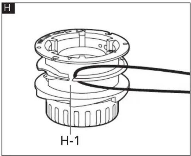
c. Check the spool retainer (H-1) and spool base for worn or damaged parts.
d. Fold the cutting line in half and hook the folded end of the cutting line (See Fig H).
e. Wind the line, in two even and tight layers, onto the spool retainer (H-1).

NOTE
Failure to wind the line in the direction indicated will cause the trimmer head to operate incorrectly.
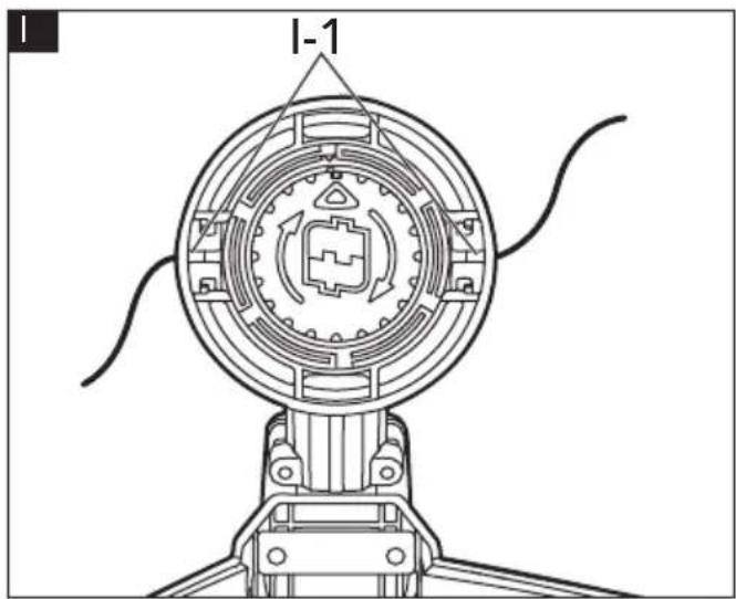
f. Place the ends of the line in two opposite eyelets (I-1) (See Fig I).
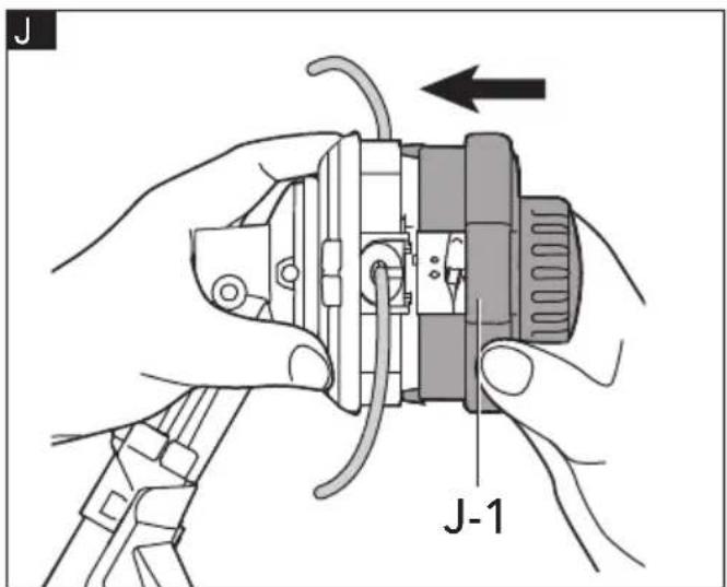
g. Align the two tabs on the spool base (J-1) with the slots on trimmer head and press it until it snaps into place (See Fig J).

NOTE
Make sure that the tabs on the spool base snap into place, otherwise the spool will come out during operation.
You can replace the new line in another way:
a. Press the two release tabs on the spool base and remove the spool retainer.
b. Reinstall the spool retainer in such a way that the threading hole (K-1) on the spool retainer is aligned with one of the eyelets (See Fig K).
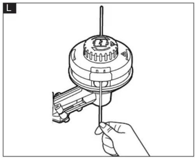
c. Insert the new line into the eyelet. Feed the line until the end of the line comes out of the other side eyelet of the spool base (See Fig L).
d. Pull the line from the other side until equal amounts of line appear on both sides.
e. Hold the spool base and rotate the bump head in the direction indicated by the arrow to wind the cutting line into the trimmer head (See Fig M).
f. Push down on the bump head and check for proper installation of the cutting line.
Transmission Gears Lubrication (See Fig N)
The transmission gears in the gear case (N-2) need be lubricated periodically with gear grease. Check the gear case grease level about every 50 hours of operation by removing the sealing screw (N-1) on the side of the case.
If no grease can be seen on the sides of the gear, follow the steps below to fill with gear grease up to 3/4 capacity.
Do not completely fill the transmission gear case (N-2).
a. Hold the line trimmer attachment on its side so that the sealing screw (N-1) is facing upwards.
b. Use a multi-function wrench (not included) to loosen and remove the sealing screw (N-1).
c. Use a grease syringe (not included) to inject some grease into the lubrication opening, taking care not to exceed 3/4 capacity.
d. Tighten the sealing screw (N-1) after injection.
Disposal information

WARNING!
Render redundant power tools unusable:
- mains operated power tool by removing the power cord,
- battery operated power tool by removing the battery.

EU countries only
Do not throw electric power tools into the household waste!
In accordance with the European Directive 2012/19/EU on Waste Electrical and Electronic Equipment and transposition into
national law used electric power tools must be collected separately and recycled in an environmentally friendly manner.

Raw material recovery instead of waste disposal.
Device, accessories and packaging should be recycled in an environmentally friendly manner. Plastic parts are identified for recycling according to material type.

WARNING!
Do not throw batteries into the household waste, fire or water. Do not open used batteries.
EU countries only:
In accordance with Directive 2006/66/EC defective or used batteries must be recycled.

NOTE
Please ask your dealer about disposal options!
CE-Declaration of conformity
We declare under our sole responsibility that the product described under "Technical specifications" conforms to the following standards or normative documents: EN 62841 in accordance with the regulations of the directives 2014/30/EU, 2006/42/EG, 2011/65/EU.
Responsible for technical documents:
Technical Director Head of Quality
Department (QD)
Declaration of Conformity
We as the manufacturer: FLEX
declare under our sole responsibility, that the product(s) described under „Technical specifications“ fulfills all the relevant provisions of The Supply of Machinery
(Safety) Regulations S.I. 2008/1597 and also fulfills all the relevant provisions of the following UK Regulations:
Electromagnetic Compatibility Regulations
S.I. 2016/1091, The Restriction of the Use of
Certain Hazardous Substances in Electrical and Electronic Equipment Regulations
S.I. 2012/3032 and are manufactured in accordance with the following designated Standards:
BS EN 62841-1:2015
IEC 62841-4-4:2020
BS EN IEC 55014-1:2021
BS EN IEC 55014-2:2021
Place of declaration: Steinheim, Germany.
Responsible person: Peter Lameli, Technical
Contact details for Great Britain: FLEX Power
Tools Limited, Unit 8 Anglo Office Park, Lincoln Road, HP 12, 3RH Buckinghamshire, United Kingdom.

Technical Director Head of Quality
Department (QD)
08.20.2023
Exemption from liability
The manufacturer and his representative are not liable for any damage and lost profit due to interruption in business caused by the product or by an unusable product.
The manufacturer and his representative are not liable for any damage which was caused by improper use of the product or by use of the product with products from other manufacturers.
