
CHE 5-40 SDS-max - Drill Flex - Free user manual and instructions
Find the device manual for free CHE 5-40 SDS-max Flex in PDF.


| Product type | Rotary hammer and chipping hammer |
| Brand | Flex |
| Model | CHE 5-40 SDS-max |
| Rated power input | 1150 W |
| No-load speed | 380 rpm |
| No-load impact rate | 2900 bpm |
| Max. impact energy (EPTA 05/2009) | 10 J |
| Max. drilling diameter in concrete | 40 mm |
| Max. drilling diameter in masonry (core bit) | 90 mm |
| Weight (EPTA 01/2003) | 6.4 kg |
| Protection class | II (double insulation) |
| Tool holder | SDS-max |
| Lubrication | Grease |
| Auxiliary handle | Yes, rotatable |
| Working mode selector | Rotary hammer / Chipping hammer / Chisel position adjustment |
| Safety clutch | Yes |
| Sound pressure level LpA | 96 dB(A) |
| Sound power level LWA | 107 dB(A) |
| Vibration value (drilling) | 8.9 m/s² (uncertainty K=1.5) |
| Vibration value (chipping) | 14.2 m/s² (uncertainty K=1.5) |
| Power supply | Mains, 230 V |
| Maintenance | Regular cleaning of ventilation slots; self-cutting carbon brushes; replacement by authorized service center |
| Safety | Wear safety glasses, ear protection, respiratory protection recommended |
Frequently Asked Questions - CHE 5-40 SDS-max Flex
User questions about CHE 5-40 SDS-max Flex
0 question about this device. Answer the ones you know or ask your own.
Ask a new question about this device
Download the instructions for your Drill in PDF format for free! Find your manual CHE 5-40 SDS-max - Flex and take your electronic device back in hand. On this page are published all the documents necessary for the use of your device. CHE 5-40 SDS-max by Flex.
USER MANUAL CHE 5-40 SDS-max Flex
natural_image
Illustration of a handheld drill bit with warning symbols (no text or labels)1 Staubschutzkappe
natural_image
Illustration of a drill presser with a circular component inserted, showing tool path and control panel (no text or symbols)natural_image
Close-up of a mechanical component with directional arrows indicating movement or flow (no text or symbols)Symbols used in this manual ..... 11
Symbols on the power tool 11
Important safety information ..... 11
Noise and vibration 12
Technical specifications 13
Overview 14
Operating instructions ..... 15
Maintenance and care 17
Disposal information 18
C€-Declaration of Conformity 18
Exemption from liability 18
Symbols used in this manual

WARNING!
Denotes impending danger.
Non-observance of this warning may result in death or extremely severe injuries.

CAUTION!
Denotes a possibly dangerous situation.
Non-observance of this warning may result in slight injury or damage to property.

NOTE!
Denotes application tips and important information.
Symbols on the power tool

Before switching on the power tool, read the operating manual!
Wear goggles!

Wear ear protection!

Use lightweight breathing protection!


Disposal information for the old machine (see page 18)!
Protection class II (completely insulated)
Important safety information

WARNING!
Read all safety warnings, instructions, illustrations and specifications provided with this power tool. Failure to follow all instructions listed below may result in electric shock, fire and/or serious injury. Save all warnings and instructions for future reference.
Before using the power tool, please read and follow:
– these operating instructions,
- the "General Power Tools Safety Rules" in the enclosed booklet (leafletno.: 315.915),
– the currently valid site rules and the regulations for the prevention of accidents.
This power tool is state of the art and has been constructed in accordance with the acknowledged safety regulations.
Nevertheless, when in use, the power tool may be a danger to life and limb of the user or a third party, or the power tool or other property may be damaged. The power tool may be operated only if it is
- as intended,
– in perfect working order.
Faults which impair safety must be repaired immediately.
Intended use
The hammer drill and chisel hammer CHE 5-40 SDS-max is designed
– for commercial use in industry and trade,
– for hammer drilling in masonry and concrete for compound/injection anchor attachment and through-holes,
– for simple trimming work to remove plaster, masonry and light concrete,
– to be used with suitable tools recommended by the manufacturer for this power tool.
Safety instructions for hammers
■ Wear ear protectors. Exposure to noise can cause hearing loss.
■ Use auxiliary handle(s), if supplied with the tool. Loss of control can cause personal injury.
■ Hold power tool by insulated gripping surfaces, when performing an operation where the cutting accessory may contact hidden wiring or its own cord. Cutting accessory contacting a "live" wire may make exposed metal parts of the power tool "live" and could give the operator an electric shock.
Safety instructions when using long drill bits with rotary hammers
■ Always start drilling at low speed and with the bit tip in contact with the workpiece.
At higher speeds, the bit is likely to bend if allowed to rotate freely without contacting the workpiece, resulting in personal injury.
■ Apply pressure only in direct line with the bit and do not apply excessive pressure. Bits can bend, causing breakage or loss of control, resulting in personal injury.
Additional safety instructions
■ Use suitable detectors to determine if utility lines are hidden in the work area or call the local utility company for assistance. Contact with electric lines can lead to fire and electric shock. Damaging a gas line can lead to explosion. Penetrating a water line causes property damage or may cause an electric shock.
■ When working with the machine, always hold it firmly with both hands and provide for a secure stance. The power tool is guided more secure with both hands.
- Secure the workpiece. A workpiece clamped with clamping devices or in a vice is held more secure than by hand.
■ Do not use the power tool if it has a damaged power cord. Do not touch the damaged power cord and pull out the mains plug if the power cord is damaged during work. Damaged power cords increase the risk of an electric shock.
■ Only use tools with SDS-max tool holder. Pull on the tool to check that it is locked properly.
■ Have a damaged dust cap replaced immediately. The dust cap prevents the ingress of dust into the tool holder.
■ Dust released from materials, such as lead paints, some types of wood, minerals and metal, may be hazardous to the operator or people in the vicinity. Inhaling or touching such dust may result in respiratory diseases and/or allergic reactions.
- Ensure the workplace is well ventilated.
- If possible, use external dust extraction.
- It is recommended to wear a respirator mask belonging to filter class P2.
■ Do not work on materials which release hazardous substances (e.g. asbestos).
■ Identify the power tool with stickers only. Do not drill any holes into the housing.
■ The mains voltage and the voltage specifications on the rating plate must correspond.
Noise and vibration
The noise and vibration values have been determined in accordance with EN 62841.
The A evaluated noise level of the power tool is typically:
– Sound pressure level L _pA : 96 dB(A);
– Sound power level L _WA : 107 dB(A);
– Uncertainty K: 3 dB.
Total vibration value:
- when hammer drilling:
– Emission value a_h : 8.9 m/s 2
– Uncertainty K: 1.5 m/s ^2
- when chiselling:
- Emission value a_h : 14.2 m/s
– Uncertainty K: 1.5 m/s ^2
ATTENTION!
The indicated measurements refer to new power tools. Daily use causes the noise and vibration values to change.

NOTE!
The vibration emission level given in this information sheet has been measured in accordance with a standardised test given in EN 62841 and may be used to compare one tool with another. It may be used for a preliminary assessment of exposure.
The declared vibration emission level represents the main applications of the tool. However if the tool is used for different applications, with different accessories or poorly maintained, the vibration emission may differ. This may significantly increase the exposure level over the total working period.
For a precise estimation of the vibration load the times should also be considered during which the power tool is switched off or even running, but not actually in use. This may significantly decrease the exposure level over the total working period.
Identify additional safety measures to protect the operator from the effects of vibration such as: maintain the tool and the accessories, keep the hands warm, organisation of work patterns.

CAUTION!
Wear ear protection at a sound pressure above 85 dB(A).
Technical specifications
| Hammer drill and chisel hammer | CHE 5-40 SDS-max | |
| Rated power W 1150 | ||
| Idle speed | min^-1 | 380 |
| Impact number at no load | min^-1 | 2900 |
| Max. single impact energy (according to "EPTA-procedure 05/2009") | J | 10 |
| Lubrication Grease | ||
| Tool holder SDS-max | ||
| Max. drill diameter – Concrete – Masonry (HM drill bit) | mm mm | 40 90 |
| Weight according to “EPTA-procedure 01/2003” | kg 6.4 | |
| Protection class II / | 回 | |
Overview

1 D u s t c a p
2 Locking sleeve
3 Rotary knob for operating mode
4 Vibration damper
5 S w i t c h
6 Handle
7 Power cord
8 Auxiliary handle
9 Rating plate *
10 Thumb wheel for selecting speed and impact rate
11 LED: standby
12 Tool grease
* not visible
Operating instructions
Before switching on the power tool
Unpack power tool and accessories and check that no parts are missing or damaged.
Adjusting the auxiliary handle

WARNING!
Before performing any work on the electric power tool, pull out the mains plug.

CAUTION!
Use electric power tool with attached auxiliary handle only.
The auxiliary handle can be swivelled into any position to ensure safe and fatigue-free working.
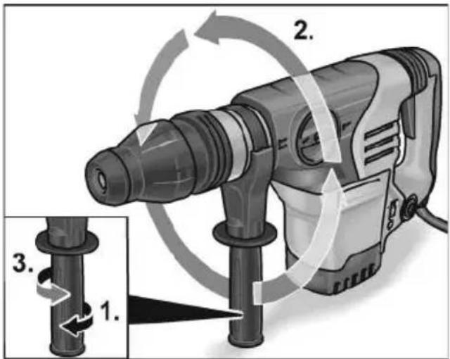
■ Release the clamping by turning the auxiliary handle counterclockwise (1.).
■ Swivel the auxiliary handle into the desired position (2.).
■ Secure the adjustment by turning the auxiliary handle clockwise (3.).
Changing the tool

WARNING!
Before performing any work on the electric power tool, pull out the mains plug.

CAUTION!
Used insertion tools may become hot. Wear protective gloves!

NOTE!
Tools used must have an SDS-max shank. Inserting the tools
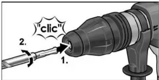
■ Clean and lightly grease the shaft of the insertion tool.
■ Check dust cap.
- Clean dirty cap.
- Have a defective dust cap replaced.
■ Insert the cutting accessory (1.) and turn (2.) until it locks.
■ Check lock by pulling on the insertion tool.
Removing the tools

■ Pull locking sleeve backwards (1.).
■ Remove insertion tool (2.).
Setting operating mode

CAUTION!
Do not change operating mode until the electric power tool is at a standstill.

■ Turn the rotary knob until it audibly engages in the required operating mode:
- Hammer drilling

-
Chiselling
-
Setting the chisel position (see below)

NOTE!
- The rotary knob must audibly click into place in all positions.
- Do not switch on the power tool in the position for setting the chisel position (3.).
Setting the chisel position
The chisel can be adjusted in 12 positions (moved 30° in each case).
■ Set the rotary knob for operating mode to the position shown.
■ Turn the chisel until the chisel is at the required angle.

natural_image
Illustration of a drill presser with a circular component inserted, showing mechanical components and a close-up view of the drill (no text or symbols present)■ Move rotary knob for operating mode to the symbol.
Switching on the power tool

natural_image
Close-up of a mechanical component with directional arrows indicating movement or force (no text or symbols)■ Press and hold down the switch. Switch off the machine:
■ Release the switch.
Safety clutch

CAUTION!
If the safety clutch trips, switch off the power tool immediately!
The safety clutch disconnects the motor from the tool if a preset torque limit value is exceeded. The insertion tool stops.
As a result, the motor and gears are protected from damage.
Operating instructions
i NOTE!
The hammer mechanism starts to work only above a certain operating temperature. When working at low ambient temperature, press the tool tip firmly against the work surface while the tool is in operation. Repeat as required until the operating temperature is reached and the hammer mechanism is working.
Hammer drilling
- Move rotary knob for operating mode to the symbol.
- Insert drill bit.
- Swivel the auxiliary handle into the required position.
- Insert mains plug.
- Grip electric power tool with both hands and assume working position.
- Position drill bit and switch on electric power tool.
- When hammer drilling, gently press electric power tool forwards. Excessive pressure does not reduce the drilling time but the service life of the drill bit!
- After drilling, switch off the power tool.
- Pull out the mains plug.
Chiselling
- Insert chisel.
- Set the rotary knob for operating mode to the position for setting the chisel position.
- Turn chisel into the required position.
- Move rotary knob for operating mode to the symbol.
- Swivel the auxiliary handle into the required position.
- Insert mains plug.
- Grip electric power tool with both hands and assume working position.
- Switching on the power tool.
- When chiselling, gently press electric power tool forwards to prevent it from jumping.
- After working, switch off the power tool.
- Pull out the mains plug.
Other information
- The use of "sharp" insertion tools increases performance and the service life of the electric power tool.
- Work preferably in intervals: work 30 sec., cool down 90 sec..
- After work, clean the electric power tool and store in the carrying case in a dry location.
Maintenance and care
WARNING!
Before performing any work on the electric power tool, pull out the mains plug.
Cleaning
Regularly clean the power tool and ventilation slots. Frequency of cleaning is dependent on the material and duration of use.
Regularly blow out the housing interior and motor with dry compressed air.
Carbon brushes
The electric power tool features cut-off carbon brushes.
When the cut-off carbon brushes reach their wear limit, the electric power tool switches off automatically.
NOTE!
Use only original parts supplied by the manufacturer for replacement purposes. If non-original parts are used, the guarantee obligations of the manufacturer will be deemed null and void.
When the power tool is being used, the carbon brushes can be seen sparking through the rear air inlet apertures. If the carbon brushes are sparking excessively, switch off the electric power tool immediately. Take your electric power tool to a customer service centre authorised by the manufacturer.
Gears
i NOTE!
Do not loosen the screws on the gear head during the warranty period.
Non-compliance will deem the guarantee obligations of the manufacturer null and void.
The electric power tool has an grease lubrication. Have the grease changed/topped up by a customer service workshop authorised by the manufacturer.
Repairs
Repairs may be carried out by an authorised customer service centre only.
X attachment cord
If the supply cord of this power tool is damaged, it must be replaced by a specially prepared cord available through the FLEX service organization.
Spare parts and accessories
Other accessories, in particular insertion tools, can be found in the manufacturer's catalogues.
Exploded drawings and spare-part lists can be found on our homepage: www.flex-tools.com
Disposal information

WARNING!
Render redundant power tools unusable by removing the power cord.

EU countries only.
Do not throw electric power tools into the household waste!
In accordance with the European Directive 2012/19/EU on Waste Electrical and Electronic Equipment and transposition into national law used electric power tools must be collected separately and recycled in an environmentally friendly manner.
i NOTE!
Please ask your dealer about disposal options!
CE-Declaration of Conformity
We declare under our sole responsibility that the product described under “Technical specifications” conforms to the following standards or normative documents:
EN 62841 in accordance with the regulations of the directives 2014/30/EU, 2006/42/EC, 2011/65/EU.
Responsible for technical documents: FLEX-Elektrowerkzeuge GmbH, R & D Bahnhofstrasse 15, D-71711 Steinheim/Murr

Peter Lameli Technical Head

Klaus Peter Weinper Head of Quality Department (QD)
30.11.2022
Exemption from liability
The manufacturer and his representative are not liable for any damage and lost profit due to interruption in business caused by the product or by an unusable product.
The manufacturer and his representative are not liable for any damage which was caused by improper use of the power tool or by use of the power tool with products from other manufacturers.
Table des matières
natural_image
Illustration of a drill presser with a circular component inserted, showing mechanical components and a close-up view of the drill (no text or symbols present)natural_image
Close-up of a mechanical component with directional arrows indicating movement or flow (no text or symbols)Peter Lameli Technical Head
Klaus Peter Weinper Head of Quality Department (QD)
natural_image
Illustration of a drill presser with a circular component inserted, showing mechanical components and a close-up view of the drill (no text or symbols present)natural_image
Close-up of a mechanical component with directional arrows indicating movement or force (no text or symbols)natural_image
Illustration of a drill presser operating a washing machine with a circular component inset (no text or symbols)natural_image
Close-up of a mechanical component with directional arrows indicating movement or flow (no text or symbols)Desmontar as ferramentas

natural_image
Illustration of a drill presser with a circular component inserted into the drill bit, alongside a close-up view of its internal structure (no text or symbols present)natural_image
Close-up of a mechanical component with directional arrows indicating movement or flow (no text or symbols)EN 62841 de acordo com as
natural_image
Illustration of a drill presser with a circular component inserted into the tool, alongside a close-up view of its internal structure (no text or symbols present)natural_image
Close-up of a mechanical component with directional arrows indicating movement or flow (no text or symbols)Peter Lameli Technical Head
Klaus Peter Weinper Head of Quality Department (QD)
natural_image
Illustration of a drill presser with a circular component inserted into the drill bit, alongside a close-up view of its internal structure (no text or symbols present)natural_image
Close-up of a mechanical component with directional arrows indicating movement or flow (no text or symbols)Peter Lameli Technical Head
Klaus Peter Weinper Head of Quality Department (QD)
30.11.2022
- under hammerboring:
- Emisjonsverdi a_h : 8,9 m/s
- Usikkerhet K: 1,5 m/s ^2
- under meisling:
- Emisjonsverdi a_h : 14,2 m/s ^2
– Usikkerhet K: 1,5 m/s ^2
OBS!
1 Deksel for støvbeskyttelse
2 Låsehylse
3 Dreieknapp for arbeidsmodus
4 Vibrasjonsdemping
5 B r y t e r
6 Håndtak
7 Strømkabel
■ Trekk läsehylsen bakover (1.).
■ Ta ut verktøyet (2.).
natural_image
Illustration of a drill presser with a circular component inserted into the drill bit, alongside a close-up view of its internal structure (no text or symbols)■ Dreieknappen for arbeidsmodus settes på symbolet
natural_image
Close-up of a mechanical component with directional arrows indicating movement or flow (no text or symbols)natural_image
Illustration of a drill presser with a circular component inserted, showing blade and handle mechanism (no text or symbols)natural_image
Close-up of a mechanical component with directional arrows indicating movement or flow (no text or symbols)Peter Lameli Technical Head
Klaus Peter Weinper Head of Quality Department (QD)
30.11.2022
natural_image
Illustration of a drill presser operating a washing machine with a circular component inserted (no text or symbols)natural_image
Close-up of a mechanical component with directional arrows indicating movement or flow (no text or symbols)Peter Lameli Technical Head
Klaus Peter Weinper Head of Quality Department (QD)
30.11.2022
natural_image
Illustration of a drill presser with a circular component inserted, alongside a close-up of its internal components (no text or symbols)natural_image
Close-up of a mechanical component with directional arrows indicating movement or flow (no text or symbols)natural_image
Illustration of a drill presser with a circular component inserted into it, showing mechanical components and a close-up view of the drill (no text or symbols present)natural_image
Close-up of a mechanical component with directional arrows indicating movement or flow (no text or symbols)Peter Lameli
Technical Head
Klaus Peter Weinper
Head of Quality
Department (QD)
30.11.2022
natural_image
Vertical sequence of icons representing various workplace and safety symbols (person, helmet, gear, worker, phone, trash bin) without any text or labels.natural_image
Illustration of a drill presser with a circular component inserted, alongside a close-up of its internal components (no text or symbols)natural_image
Close-up of a mechanical component with directional arrows indicating movement or flow (no text or symbols)Peter Lameli
Technical Head
Klaus Peter Weinper
Head of Quality
Department (QD)
-
- 30.
natural_image
Illustration of a drill presser with a circular component inserted, showing internal components and a close-up view of the drill (no text or symbols present)natural_image
Close-up of a mechanical component with directional arrows indicating movement or flow (no text or symbols)
Peter Lameli
Technical Head

Klaus Peter Weinper Head of Quality Department (QD)
30.11.2022
natural_image
Illustration of a drill presser with a circular component inserted, showing internal components and a close-up view of the device (no text or symbols present)■ Nastavte otočný gombík pre pracovný režim na symbol
natural_image
Close-up of a mechanical component with directional arrows indicating movement or flow (no text or symbols)
Peter Lameli
Technical Head
Klaus Peter Weinper Head of Quality Department (QD)
30.11.2022
natural_image
Illustration of a drill presser with a circular component inserted, showing mechanical components and a close-up view of the drill (no text or symbols present)natural_image
Close-up of a mechanical component with directional arrows indicating movement or flow (no text or symbols)
Peter Lameli
Technical Head

Klaus Peter Weinper Head of Quality Department (QD)
30.11.2022
natural_image
Illustration of a drill presser operating a washing machine with a circular component inset (no text or symbols)natural_image
Close-up of a mechanical component with directional arrows indicating movement or flow (no text or symbols)Peter Lameli Technical Head
Klaus Peter Weinper Head of Quality Department (QD)
2022-11-30
natural_image
Illustration of a drill presser with a circular component inserted, showing internal components and a close-up view of the drill (no text or symbols present)■ Darba režima pagriežamo pogu pagrieziet pret simbolu
natural_image
Close-up of a mechanical component with directional arrows indicating movement or flow (no text or symbols)Peter Lameli Technical Head
Klaus Peter Weinper Head of Quality Department (QD)
30.11.2022
natural_image
Illustration of a drill presser with a circular inset showing a wheel blade (no text or symbols)natural_image
Close-up of a mechanical component with directional arrows indicating movement or flow (no text or symbols)
Peter Lameli
Technical Head

Klaus Peter Weinper Head of Quality Department (QD)
30.11.2022


- Symbols used in this manual
- WARNING!
- CAUTION!
- NOTE!
- Symbols on the power tool
- Important safety information
- Intended use
- Safety instructions for hammers
- Safety instructions when using long drill bits with rotary hammers
- Additional safety instructions
- Noise and vibration
- ATTENTION!
- Overview
- Operating instructions
- Before switching on the power tool
- Adjusting the auxiliary handle
- Changing the tool
- Removing the tools
- Setting operating mode
- Setting the chisel position
- Switching on the power tool
- Safety clutch
- i NOTE!
- Hammer drilling
- Chiselling
- Other information
- Maintenance and care
- Cleaning
- Carbon brushes
- Gears
- Repairs
- X attachment cord
- Spare parts and accessories
- Disposal information
- CE-Declaration of Conformity
- Exemption from liability
- Table des matières
- Desmontar as ferramentas
- OBS!
Brand : Flex
Model : CHE 5-40 SDS-max
Category : Drill