
DH 5 SDS-max - Drill Flex - Free user manual and instructions
Find the device manual for free DH 5 SDS-max Flex in PDF.


| Product Type | SDS-max Rotary Hammer |
| Brand | Flex |
| Model | DH 5 SDS-max |
| Nominal Power | 1500 W |
| Supply Voltage | 230 V ~ 50 Hz |
| Chuck Type | SDS-max |
| Impact Energy | 8.5 J |
| No-load Impact Rate | 0 – 2700 blows/min |
| No-load Speed | 0 – 600 rpm |
| Max. Drilling Diameter in Concrete | 40 mm |
| Max. Drilling Diameter in Steel | 13 mm |
| Max. Drilling Diameter in Wood | 40 mm |
| Weight | 6.8 kg |
| Dimensions (L x W x H) | 480 x 110 x 290 mm |
| Sound Power Level (LWA) | 105 dB(A) |
| Sound Pressure Level (LpA) | 94 dB(A) |
| Hand-arm Vibration (Drilling) | 15 m/s² |
| Protection Class | II (double insulation) |
| Main Functions | Drilling, hammer drilling, chiseling |
| Variable Speed | Yes, variable |
| Rotation Direction | Left/Right |
| Anti-vibration Handle | Yes, auxiliary handle |
| Maintenance and Cleaning | Clean ventilation slots with a brush, periodic lubrication of the chuck |
| Spare Parts and Repairability | Carbon brushes, brush holders, chuck, switch available |
Frequently Asked Questions - DH 5 SDS-max Flex
User questions about DH 5 SDS-max Flex
0 question about this device. Answer the ones you know or ask your own.
Ask a new question about this device
Download the instructions for your Drill in PDF format for free! Find your manual DH 5 SDS-max - Flex and take your electronic device back in hand. On this page are published all the documents necessary for the use of your device. DH 5 SDS-max by Flex.
USER MANUAL DH 5 SDS-max Flex
natural_image
3D rendering of a black handheld power tool with attached cylindrical housing and cable (no text or symbols visible)de Originalbetriebsanleitung 3
en Original operating instructions 11
fr Notice d'instructions d'origine 18
it Istruzioni per l'uso originali 26
es Instrucciones de funcionamiento originales 34
pt Instruções de serviço originais 42
nl Originele gebruiksaanwijzing 50
da Originale driftsvejledning 58
no Originale driftsanvisningen 65
sv Originalbruksanvisning 72
fi Alkuperäinen käyttöohjekirja 79
el Auθεντικές οδηγίες χειρισμού 86
pl Oryginalna instrukcja obsługi 94
hu Eredeti üzemeltetési útmutató 102
cs Originální návod k obsluze 110
sk Originálny návod na obsluhu 117
et Originaalkasutusjuhend 124
It Originali naudojimo instrukcija 131
Iv Lietošanas pamācības oriģināls 139
ru Оригинальная инструкция
по эксплуатации 147
Inhalt
natural_image
Diagram of a mechanical device with circular arrows indicating rotational flow or cycle (no text or symbols)natural_image
Close-up of a black handheld device with a circular arrow indicating motion, no visible text or symbolsnatural_image
Close-up of a black handheld device with directional arrows indicating movement or force (no text or symbols visible)natural_image
Close-up of a black handheld device with a circular arrow indicating motion (no text or symbols visible)Klaus Peter Weinper Head of Quality Department (QD)
Symbols used in this manual ..... 11
Technical specifications ..... 11
Overview 12
Important safety information ..... 13
Noise and vibration 14
Operating instructions 14
Maintenance and care 16
Disposal information 17
C€-Declaration of Conformity ..... 17
Exemption from liability 17
Symbols used in this manual

WARNING!
Denotes impending danger.
Non-observance of this warning may result indeath or extremely severe injuries.

CAUTION!
Denotes a possibly dangerous situation.
Non-observance of this warning may result insight injury or damage to property.

NOTE!
Denotes application tips and important information.
Symbols on the power tool

Before switching on the power tool, read the operating manual!

Wear goggles!

Wear ear protection!

Disposal information for the old machine!
(See page 17)
Technical specifications
| Chisel hammer DH 5 | SDS-max | |
| Rated power W 1050 | ||
| Impact number at no load | min^-1 | 3500 |
| Max. single impact energy (according to "EPTA-procedure 05/2009") | J | 6.7 |
| Tool holder SDS max. | ||
| Lubrication Grease | ||
| Weight according to “EPTA-procedure 01/2003” | kg 5.4 | |
Overview

1 Dust cap
2 Locking sleeve
3 Rotary ring for chisel setting
4 S w i t c h
5 Locking button
6 H a n d l e
7 Clamping screw for auxiliary handle
8 Auxiliary handle
9 Power cord
10 Tool grease
11 Rating plate *
* not visible
Important safety information

WARNING!
Read all safety warnings and all
instructions. Failuretofollow the warnings and instructions may result inelectric shock, fire and/or serious injuries. Save all warnings and instructions for future reference.
Before using the power tool, please read and follow:
– these operating instructions,
- the "General safety instructions" on the handling of power tools in the enclosed booklet (leaflet-no.: 315.915),
– the currently valid site rules and the regulations for the prevention of accidents.
This power tool is state of the art and has been constructed in accordance with the acknowledged safety regulations.
Nevertheless, when in use, the power tool may be a danger to life and limb of the user or a third party, or the power tool or other property may be damaged. The power tool may be operated only if it is
- as intended,
– in perfect working order.
Faults which impair safety must be repaired immediately.
Intended use
The chisel hammer DH 5 SDS-max is designed
-for commercial use in industry and trade,
-for moderately difficult trimming and break-through work in concrete and masonry as well as for removing plaster and tiles,
-to be used with suitable tools recommended by the manufacturer for this power tool.
Safety instructions for hammers
■ Wear ear protection. The effect of noise may result in loss of hearing.
■ Use auxiliary handles supplied with the power tool. The loss of control may result in injuries.
If the insertion tool is at risk of coming into contact with concealed power cables or the power cord itself, hold the power tool by the insulated grip surfaces only. Contact with a live cable may also cause metal parts of the appliance to become live and result in an electric shock.
■ Use suitable detectors to detect concealed power supply cables or consult your local supply company.
Contact with electric cables may result in a fire and/or electric shock.
A damaged gas pipe may cause an explosion. Drilling into a water pipe will cause damage to property or may cause an electric shock.
■ When working, hold the electric power tool firmly with both hands and ensure that you have a secure footing.
The electric power tool is controlled more securely if held with both hands.
■ Secure the workpiece.
A workpiece is held more securely in a clamping device than by hand.
■ Do not use the electric power tool if it has a damaged power cord.
Do not touch the damaged power cord and pull out the mains plug if the power cord is damaged during work.
Damaged power cords increase the risk of an electric shock.
Special safety instructions
■ Do not work on cut materials which release hazardous substances (e.g. asbestos). Take precautions if hazardous, combustible or explosive dust is likely to occur. Wear protective dust mask. If available, use dust extraction equipment.
■ Identify the power tool with stickers only. Do not drill any holes into the housing.
■ The mains voltage and the voltage specifications on the rating plate must correspond.
Noise and vibration
The noise and vibration values have been determined in accordance with EN 60745.
The A evaluated noise level of the power tool is typically:
—Sound pressure level: 89 dB(A);
—Sound power level: 100 dB(A);
—Uncertainty: K = 3 dB.
Total vibration value (when chiseling):
$$ - \text { Emission value: a } \quad h = 1 1. 5 \mathrm{m} / \mathrm{s} ^ {2} $$
$$ - \text { Uncertainty: } K = 1. 5 \mathrm{m} / \mathrm{s} $$

ATTENTION!
The indicated measurements refer to new power tools. Daily use causes the noise and vibration values to change.

NOTE!
The vibration emission level given in this information sheet has been measured in accordance with a standardised test given in EN 60745 and may be used to compare one tool with another. It may be used for a preliminary assessment of exposure. The declared vibration emission level represents the main applications of the tool.
However if the tool is used for different applications, with different accessories or poorly maintained, the vibration emission may differ.
This may significantly increase the exposure level over the total working period.
For a precise estimation of the vibration load the times should also be considered during which the power tool is switched off or even running, but not actually in use.
This may significantly decrease the exposure level over the total working period.
Identify additional safety measures to protect the operator from the effects of vibration such as: maintain the tool and the accessories, keep the hands warm, organisation of work patterns.

CAUTION!
Wear ear protection at a sound pressure above85 dB(A).
Operating instructions
Before switching on the power tool
Unpack power tool and accessories and check that no parts are missing or damaged.
Adjusting the auxiliary handle

WARNING!
Before performing any work on the electric power tool, pull out the mains plug.

CAUTION!
Use electric power tool with attached auxiliary handle only.
The auxiliary handle can be swivelled into any position to ensure safe and fatigue-free working.
■ Loosen the clamping screw by turning it anti-clockwise.

natural_image
Illustration of a mechanical drill press with circular motion arrows indicating cycle (no text or symbols)■ Swivel the auxiliary handle into the required position (radial, axial).
■ Retighten the auxiliary handle by turning the clamping screw clockwise.
Inserting the tools

WARNING!
Before performing any work on the electric power tool, pull out the mains plug.

CAUTION!
Used insertion tools may become hot. Wearprotective gloves!

■ Clean and lightly grease the shaft of the insertion tool.
■ Check dust cap.
- Clean dirty cap.
- Replace defective dust cap.
■ Insert insertion tool and turn until it locks.
■ Check lock by pulling on the insertion tool.
Removing the tools

WARNING!
Before performing any work on the electric power tool, pull out the mains plug.

CAUTION!
Used insertion tools may become hot. Wearprotective gloves!

■ Pull locking sleeve backwards (1.).
■ Remove insertion tool (2..).
Setting the chisel position
The chisel can be adjusted in 12 positions (moved 30° in each case).

■ Pull rotary ring for chisel setting forwards and hold (1.).
■ Turn chisel until the chisel is at the required angle (2.).
■ Release rotary ring for chisel setting (3.).
Switching on the power tool
Without locking the switch:

natural_image
Close-up of a black handheld device with a circular arrow indicating rotation (no text or symbols visible)■ Press and hold down the switch.
Switch off the machine:
■ Release the switch.
Locking the switch:

CAUTION!
Following a power failure, the switched-on machine will start running again. If the power fails, switch off the electric power tool immediately!

natural_image
Close-up of a robotic arm with directional arrows indicating movement or force (no text or symbols)■ Press and hold down the switch.
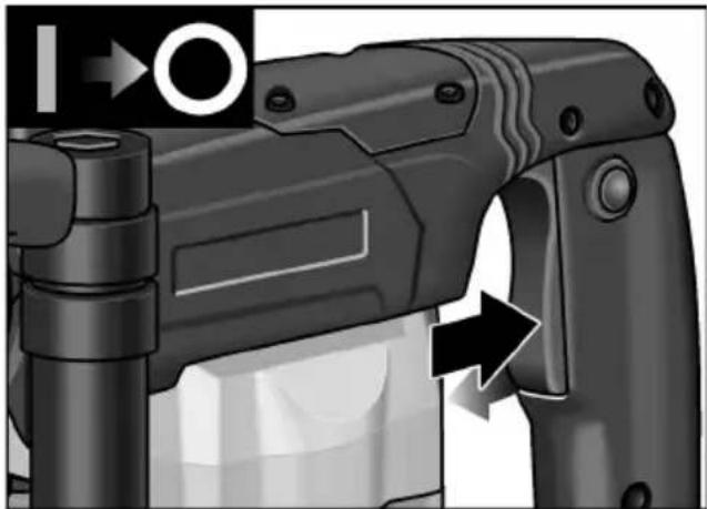
■ Press locking button to lock the switch. Switch off the machine:

natural_image
Close-up of a black handheld device with a circular button labeled 'I' and an arrow pointing to the handle (no readable text or symbols)■ Press and release the switch.
Operating instructions
- Insert chisel.
- Turn chisel into the required position.
- Swivel the auxiliary handle into the required position.
- Insert mains plug.
- Grip electric power tool with both hands and assume working position.
-
Switch on the power tool.
-
When chiselling, gently press electric power tool forwards to prevent it from jumping.
- After working, switch off the power tool.
- Pull out the mains plug.
Other information
—The use of “sharp” insertion tools increases performance and the service life of the electric power tool.
-Work preferably in intervals: Work 30 sec., cool down 90 sec.
—After work, clean the electric power tool and store in the carrying case in a dry location.
Maintenance and care

WARNING!
Before performing any work on the electric power tool, pull out the mains plug.
Cleaning
Regularly clean the power tool and ventilation slots. Frequency of cleaning is dependent on the material and duration of use.
Regularly blow out the housing interior and motor with dry compressed air.
Carbon brushes
The electric power tool features cut-off carbon brushes.
When the cut-off carbon brushes reach their wear limit, the electric power tool switches off automatically.

NOTE!
Use only original parts supplied by the manufacturer for replacement purposes. If non-original parts are used, the guarantee obligations of the manufacturer will be deemed null and void.
When the power tool is being used, the carbon brushes can be seen sparking through the rear air inlet apertures. If the carbon brushes are sparking excessively, switch off the electric power tool immediately.
Take your electric power tool to a customer service centre authorised by the manufacturer.
Gears

NOTE!
Do not loosen the screws on the gear head during the warranty period. Non-compliance will deem the guarantee obligations of the manufacturer null and void.
The electric power tool has grease lubrication. Have the grease changed/topped up by a customer service workshop authorised by the manufacturer.
Repairs
Repairs may be carried out by an authorised customer service centre only.
X attachment cord
If the supply cord of this power tool is damaged, it must be replaced by a specially prepared cord available through the service organization.
Spare parts and accessories
Other accessories, in particular insertion tools, can be found in the manufacturer's catalogues.
Exploded drawings and spare-part lists can be found on our homepage: www.flex-tools.com
Disposal information

WARNING!
Render redundant power tools unusable byremoving the power cord.

EU countries only.
Do not throw electric power tools into the household waste!
In accordance with the European Directive 2012/19/EG on Waste Electrical and Electronic Equipment and transposition into national law used electric power tools must be collected separately and recycled in an environmentally friendly manner.

NOTE!
Please ask your dealer about disposal options!
CE -Declaration of Conformity
We declare under our sole responsibility that the product described under “Technical specifications” conforms to the following standards or normative documents:
EN 60745 in accordance with the regulations of the directives 2004/108/EC (until 19.04.2016), 2014/30/EU (from 20.04.2016), 2006/42/EC, 2011/65/EC.
Responsible for technical documents: FLEX-Elektrowerkzeuge GmbH, R & D Bahnhofstrasse 15, D-71711 Steinheim/Murr

Eckhard Rühle Manager Research & Development (R & D)

Klaus Peter Weinper Head of Quality Department (QD)
22.07.2015
Exemption from liability
The manufacturer and his representative are not liable for any damage and lost profit due to interruption in business caused by the product or by an unusable product.
The manufacturer and his representative are not liable for any damage which was caused by improper use of the power tool or by use of the power tool with products from other manufacturers.
Table des matières
natural_image
Illustration of a mechanical drill bit with circular motion arrows indicating cycle (no text or symbols)natural_image
Close-up of a mechanical device with a directional arrow indicating motion (no text or symbols)natural_image
Close-up of a robotic arm with directional arrows indicating movement or force (no text or symbols)natural_image
Close-up of a black handheld device with directional arrows indicating movement or action (no text or symbols visible)Klaus Peter Weinper Head of Quality Department (QD)
22.07.2015
natural_image
Illustration of a drill bit with circular motion arrows indicating cycle (no text or symbols)natural_image
Close-up of a mechanical device with a handle and arrow indicating motion (no text or symbols)natural_image
Close-up of a robotic arm with directional arrows indicating movement or force (no text or symbols)natural_image
Close-up of a black handheld device with directional arrows indicating movement or force (no text or symbols)Eckhard Rühle Manager Research & Development (R & D)
Klaus Peter Weinper Head of Quality Department (QD)
22.07.2015
natural_image
Diagram of a mechanical device with circular arrows indicating rotational flow or cycle (no text or symbols)natural_image
Close-up of a black handheld device with a circular arrow indicating motion, no visible text or symbolsnatural_image
Close-up of a robotic arm with directional arrows indicating movement or force (no text or symbols)natural_image
Close-up of a black handheld device with directional arrows indicating movement or action (no text or symbols)Eckhard Rühle Manager Research & Development (R & D)
Klaus Peter Weinper Head of Quality Department (QD)
natural_image
Diagram of a mechanical device with circular arrows indicating rotational flow or cycle (no text or symbols)Desmontar as ferramentas

AVISO!
natural_image
Close-up of a robotic gun with a directional arrow indicating motion (no text or symbols)natural_image
Close-up of a robotic arm with directional arrows indicating movement or force (no text or symbols)natural_image
Close-up of a black handheld device with a circular arrow indicating motion, no visible text or symbols■ Premir e libertar o interruptor.
De hakhamer DH 5 SDS-max is bestemd
natural_image
Diagram of a mechanical power tool with circular motion arrows indicating rotational flow (no text or symbols)natural_image
Close-up of a black handheld device with a circular arrow indicating motion, no visible text or symbolsnatural_image
Close-up of a robotic arm with directional arrows indicating movement or force (no text or symbols)natural_image
Close-up of a black handheld device with a circular arrow indicating direction (no text or symbols visible)Eckhard Rühle Manager Research & Development (R & D)
Klaus Peter Weinper Head of Quality Department (QD)
natural_image
Diagram of a drill press with circular motion arrows indicating cycle (no text or symbols)natural_image
Close-up of a black handheld device with a circular arrow indicating rotation (no text or symbols visible)natural_image
Close-up of a robotic arm with directional arrows indicating movement or force (no text or symbols)■ Tryk på kontakten og hold den fast.
■ Tryk på låseknappen for at låse afbryderen.
Sluk maskinen:
natural_image
Close-up of a black handheld device with a circular arrow pointing to the right side (no visible text or symbols)Eckhard Rühle Manager Research & Development (R & D)
Klaus Peter Weinper Head of Quality Department (QD)
22.07.2015
1 Deksel for støvbeskyttelse
2 Låsehylse
3 Dreiering for innstilling av meisel
4 B r y t e r
5 Festeknapp
6 Håndtak
natural_image
Illustration of a drill bit with motion arrows indicating rotational flow (no text or symbols)natural_image
Close-up of a black handheld device with a circular arrow pointing to its side panel (no text or symbols visible)■ Trykk bryteren og hold den fast.
Slå maskinen av:
■ Slipp bryteren.
Med lås:

FORSIKTIG!
natural_image
Close-up of a black handheld device with directional arrows indicating movement or operation (no text or symbols visible)natural_image
Close-up of a black handheld device with a circular arrow indicating motion, no visible text or symbolsKlaus Peter Weinper Head of Quality Department (QD)
22.07.2015
natural_image
Diagram of a mechanical power tool with circular motion arrows indicating rotational flow (no text or symbols)natural_image
Close-up of a black handheld device with a circular arrow indicating motion, no visible text or symbolsnatural_image
Close-up of a black handheld device with directional arrows indicating movement or force (no text or symbols visible)natural_image
Close-up of a black handheld device with a circular arrow pointing to the handle (no visible text or symbols)Manager Research & Development (R & D)
Klaus Peter Weinper
Head of Quality Department (QD)
22.07.2015
natural_image
Illustration of a mechanical power tool with circular motion arrows indicating rotational flow (no text or symbols)natural_image
Close-up of a black handheld device with a circular arrow pointing to its side panel (no text or symbols visible)natural_image
Close-up of a robotic arm with directional arrows indicating movement or force (no text or symbols)natural_image
Close-up of a black handheld device with a circular arrow indicating direction (no text or symbols visible)Manager Research & Development (R & D)
Klaus Peter Weinper Head of Quality Department (QD)
22.07.2015
natural_image
Illustration of a mechanical power drill with circular motion arrows indicating cycle (no text or symbols)natural_image
Close-up of a black handheld device with a circular arrow indicating direction (no text or symbols visible)natural_image
Close-up of a black robotic gun with directional arrows indicating movement or force (no text or symbols visible)natural_image
Close-up of a black handheld device with a circular arrow indicating motion, no visible text or symbolsKlaus Peter Weinper Head of Quality Department (QD)
22.07.2015
natural_image
Illustration of a drill bit with circular motion arrows indicating cycle (no text or symbols)natural_image
Close-up of a robotic gun with a directional arrow indicating motion (no text or symbols)natural_image
Close-up of a black robotic gun with directional arrows indicating movement or force (no text or symbols)natural_image
Close-up of a black handheld device with a circular arrow indicating motion, no visible text or symbols2006/42/WE, 2011/65/WE.
natural_image
Illustration of a mechanical drill bit with circular motion arrows indicating cycle (no text or symbols)natural_image
Close-up of a black handheld device with a circular arrow indicating rotation (no text or symbols visible)natural_image
Close-up of a black handheld device with directional arrows indicating movement or operation (no text or symbols visible)natural_image
Close-up of a black handheld device with directional arrows indicating movement or force (no text or symbols visible)Eckhard Rühle
Manager Research &
Development (R & D)
Klaus Peter Weinper
Head of Quality
Department (QD)
22.07.2015
natural_image
Diagram of a drill press with circular motion arrows indicating cycle (no text or symbols)natural_image
Close-up of a black handheld device with a circular arrow indicating rotation (no text or symbols visible)natural_image
Close-up of a black handheld device with directional arrows indicating movement or force (no text or symbols visible)natural_image
Close-up of a black handheld device with a circular arrow pointing to the right side (no visible text or symbols)Eckhard Rühle
Manager Research &
Development (R & D)
22.07.2015
Klaus Peter Weinper
Head of Quality
Department (QD)
natural_image
Diagram of a drill bit with circular motion arrows indicating cycle (no text or symbols)■ Tiahnite blokovacie puzdro smerom dozadu (1.).
■ Vyberte pracovný nástroj (2.).
natural_image
Close-up of a black handheld device with a circular arrow indicating motion, no visible text or symbolsnatural_image
Close-up of a robotic arm with directional arrows indicating movement or force (no text or symbols)natural_image
Close-up of a black handheld device with a circular arrow indicating direction (no text or symbols visible)1 T o l m u k a i
2 Lukustushülss
natural_image
Illustration of a drill bit with motion arrows indicating rotational flow (no text or symbols)natural_image
Close-up of a firearm component with an arrow indicating motion, no visible text or symbolsnatural_image
Close-up of a robotic arm with directional arrows indicating movement or force (no text or symbols)natural_image
Close-up of a black handheld device with a circular arrow indicating motion, no visible text or symbolsKlaus Peter Weinper Head of Quality Department (QD)
22.07.2015
natural_image
Diagram of a mechanical power tool with circular motion arrows indicating rotational flow (no text or symbols)natural_image
Close-up of a mechanical device with a cylindrical component and an arrow indicating motion (no text or symbols visible)natural_image
Close-up of a black handheld device with directional arrows indicating movement or operation (no text or symbols visible)natural_image
Close-up of a black handheld device with directional arrows indicating movement or force (no text or symbols visible)Eckhard Rühle Manager Research & Development (R & D)
Klaus Peter Weinper Head of Quality Department (QD)
22.07.2015
natural_image
Illustration of a mechanical drill bit with circular motion arrows indicating cycle (no text or symbols)natural_image
Close-up of a firearm with a hand inserting a button, showing no text or symbols on the device itself.■ Spiediet slēdzi un turiet to nospiestu.
Ierīces izslēgšana:
■ Slēdzi atlaidiet.
Ar iefiksēšanos:

UZMANĪBU!
natural_image
Close-up of a black robotic gun with directional arrows indicating movement or force (no text or symbols visible)■ Spiediet slēdzi un turiet to nospiestu.
natural_image
Close-up of a black handheld device with directional arrows indicating movement or force (no text or symbols visible)■ Nospiediet slēdzi un atlaidiet.
Darba norādījumi
Klaus Peter Weinper Head of Quality Department (QD)
22.07.2015
natural_image
Illustration of a mechanical drill bit with circular motion arrows indicating cycle (no text or symbols)natural_image
Close-up of a black handheld device with a circular arrow indicating motion, no visible text or symbolsnatural_image
Close-up of a robotic arm with directional arrows indicating movement or force (no text or symbols)natural_image
Close-up of a black handheld device with a circular arrow pointing to the handle (no visible text or symbols)Eckhard Rühle Manager Research & Development (R & D)
Klaus Peter Weinper Head of Quality Department (QD)
22.07.2015


- Inhalt
- Symbols used in this manual
- WARNING!
- CAUTION!
- NOTE!
- Symbols on the power tool
- Technical specifications
- Overview
- Important safety information
- Read all safety warnings and all
- Intended use
- Safety instructions for hammers
- Special safety instructions
- Noise and vibration
- ATTENTION!
- Operating instructions
- Before switching on the power tool
- Adjusting the auxiliary handle
- Inserting the tools
- Removing the tools
- Setting the chisel position
- Switching on the power tool
- Locking the switch:
- Other information
- Maintenance and care
- Cleaning
- Carbon brushes
- Gears
- Repairs
- X attachment cord
- Spare parts and accessories
- Disposal information
- CE -Declaration of Conformity
- Exemption from liability
- Table des matières
- Desmontar as ferramentas
- AVISO!
- Med lås:
- FORSIKTIG!
- Ar iefiksēšanos:
- UZMANĪBU!
- Darba norādījumi
Brand : Flex
Model : DH 5 SDS-max
Category : Drill