
CI 11 18.0 - Pump Flex - Free user manual and instructions
Find the device manual for free CI 11 18.0 Flex in PDF.

| Product Type | Dual Function Inflator |
| Brand | Flex |
| Model | CI 11 18.0 |
| Power Supply | Flex 18V lithium-ion battery (not included) or 12V cigarette lighter |
| Maximum Pressure | 11 bar / 1100 kPa / 160 PSI |
| Air Flow | 408 L/min |
| Working Modes | High pressure and high volume |
| Deflation | Yes, via high volume hose |
| Digital Pressure Gauge | Yes, with target pressure setting |
| Automatic Shut-off | Yes (high pressure mode) |
| LED Lights | Yes, with dedicated switch |
| Removable Battery | Yes (Flex 18V system) |
| Battery Level Indicator | Yes (4 levels) |
| Cigarette Lighter Adapter | Included (12V cable) |
| Included Adapters | Tapered, sports needle, Presta valve, pneumatic chuck |
| High Pressure Hose | Yes, with chuck and locking clip |
| High Volume Hose | Yes, for bulky items |
| Operating Temperature | -10°C to 40°C |
| Storage Temperature | -40°C to 70°C |
| Insulation Class | III |
Frequently Asked Questions - CI 11 18.0 Flex
User questions about CI 11 18.0 Flex
0 question about this device. Answer the ones you know or ask your own.
Ask a new question about this device
Download the instructions for your Pump in PDF format for free! Find your manual CI 11 18.0 - Flex and take your electronic device back in hand. On this page are published all the documents necessary for the use of your device. CI 11 18.0 by Flex.
USER MANUAL CI 11 18.0 Flex
natural_image
Line drawing of a portable electric light bulb with control panel and display (no text or symbols)de Originalbetriebsanleitung....6
en Original operating instructions....12
fr Notice d'instructions d'origine ....18
it Istruzioni per l'uso originali....24
es Instrucciones de funcionamiento originales....30
pt Instruções de serviço originais....36
nl Originele gebruiksaanwijzing....42
da Originale driftsvejledning 48
no Originale driftsanvisningen....54
SV Originalbruksanvisning 60
fi Alkuperäinen käyttöohjekirja....66
el Auθεντικές οδηγίες χειρισμού....72
tr Orijinal işletme kılavuzu....79
pl Instrukcja oryginalna....85
hu Eredeti üzemeltetési útmutató 92
cs Originální návod k obsluze 98
sk Originálny návod na obsluhu 104
hr Originalna uputa za rad....110
sl Izvirno navodilo za obratovanje 116
ro Instructiuni de functionare originale.... 122
bg Оригинално упътване за експлоатация 128
ru Оригинальная инструкция по эксплуатации 135
et Originaalkasutusjuhend 142
It Originali naudojimo instrukcija 148
Iv Lietošanas pamācības oriģināls.... 154
ar
......160
ترجمة لإرشادات التشفيل الأصلية
A
Peter Lameli Klaus Peter Weinper Technical Head Head of Quality
Department (QD)
Symbols used in this manual

WARNING!
Denotes impending danger. Non-observance of this warning may result in death or extremely severe injuries.

CAUTION!
Denotes a possibly dangerous situation. Non-observance of this warning may result in slight injury or damage to property.

NOTE
Denotes application tips and important information
Symbols on the power tool
Vvolts

Insulation class III

To reduce the risk of injury, read the operating instructions!

Disposal information for the old machine (see page 16)!
For your safety

WARNING!
Before using the power tool, please read and follow:
– these operating instructions.
- the "General safety instructions" on the handling of power tools in the enclosed booklet (leaflet-no.: 315.915),
– the currently valid site rules and the regulations for the prevention of accidents.
This power tool is state of the art and has been constructed in accordance with the acknowledged safety regulations.
Nevertheless, when in use, the power tool may be a danger to life and limb of the user or a third party, or the power tool or other property may be damaged.
The Dual function inflator may be used only -asintended,
- in perfect working order.
Faults which impair safety must be repaired immediately.
Intended use
The Dual function inflator is designed
– for commercial use in industry and trade,
- for inflating tires, balls and other small volume items which fit the air chuck directly, or by using the supplied adapters.
– for inflating large volume items such as air beds, pools, boats, etc.
Safety instructions for dual function inflator
- Know your inflator. Read operator's manual carefully. Learn its applications and limitations, as well as the specific potential hazards related to this tool. Following this rule will reduce the risk of electric shock, fire, or serious injury.
■ Risk of bursting. Do not preset the inflator to result in an output pressure greater than marked maximum pressure of item to be inflated. Do not use at pressure greater than 160 PSI.
■ To reduce the risk of electric shock, do not expose to rain. Store indoors.
■ Inspect yearly for cracks, pin holes, or other imperfections that could cause the inflator to become unsafe. Never cut or drill holes in the inflator.
■ Make sure that the hose is free of obstructions or snags. Entangled or snarled hoses can cause loss of balance or footing and may become damaged.
■ Use the inflator only for its intended use. Do not alter or modify the unit from the original design or function.
■ Always be aware that misuse and improper handling of this inflator can cause injury to yourself and others.
■ Never leave an inflator unattended with the air hose attached.
■ Do not continue to use an inflator or hose that leaks air or does not function properly.
■ Always remove the battery pack before making adjustments, servicing an inflator, or when an inflator is not in use.
■ Do not attempt to pull or carry the inflator by the hoses.
■ Do not use the inflator as a breathing device.
■ Never direct a jet of compressed air toward people or animals. Take care not to blow dust and dirt towards yourself or others. Following this rule will reduce the risk of serious injury.
■ Protect your lungs. Wear a face or dust mask if the operation is dusty. Following this rule will reduce the risk of serious personal injury.
■ Do not use this inflator to spray chemicals. Your lungs can be damaged by inhaling toxic fumes.
- Check damaged parts. Before further use of the inflator or air tool, a guard or other part that is damaged should be carefully checked to determine that it will operate properly and perform its intended function. Check for alignment of moving parts, binding of moving parts, breakage of parts, mounting, and any other conditions that may affect its operation. A guard or other part that is damaged should be properly repaired or replaced by a SKIL factory service center or authorized FLEX service station. Following this rule will reduce the risk of shock, fire, or serious injury.
- Do not crush, drop or damage the battery pack. Do not use a battery pack or charger that has been dropped or received a sharp blow. A damaged battery is subject to explosion.
■ Properly dispose of a dropped or damaged battery immediately.
■ Do not charge a battery tool in a damp or wet location. Following this rule will reduce the risk of electric shock.
■ Allow pump to cool for five (5) minutes after each fifteen (15) minutes of continuous use.
■ Never block the inflating or deflating outlets while operating.
■ Save these instructions. Refer to them frequently and use them to instruct others who may use this handheld inflator. If you loan someone this handheld inflator, loan them these instructions also.
Noise and vibration
The noise and vibration values have been determined in accordance with EN 62841. The A evaluated noise level of the power tool is typically:
- Sound pressure level L_pA : XXX dB(A);
- Sound power level L_WA : XXX dB(A);
- Uncertainty: K = 3.0 dB.
– Total vibration value: - Emission value a_h : XXX m/s
- Uncertainty: K = 1.5 m/s
CAUTION!
The indicated measurements refer to new power tools. Daily use causes the noise and vibration values to change.
NOTE
The vibration emission level given in this information sheet has been measured in accordance with a standardised test given in EN 62841 and may be used to compare one tool with another.
It may be used for a preliminary assessment of exposure. The declared vibration emission level represents the main applications of the tool. However if the tool is used for different applications, with different accessories or poorly maintained, the vibration emission may differ. This may significantly increase the exposure level over the total working period. For a precise estimation of the vibration load the times should also be considered during which the power tool is switched off or even running, but not actually in use. This may significantly decrease the exposure level over the total working period. Identify additional safety measures to protect the operator from the effects of vibration such as: maintain the tool and the accessories, keep the hands warm, organisation of work patterns.
CAUTION!N!
Wear ear protection at a sound pressure above 85 dB(A)
Technical specifications
| Dual function inflator | ||
| Battery AP 18.0/2 | 2.5 AP 18.0/5 | 0 |
| Working temperature | -10~40°C | |
| Storage temperature | -40~70°C | |
| Charging temperature | 4~40°C | |
| Rated voltage | 18V Flex Lithium Battery Pack or 12V Vehicle Power | |
| Maximum air pressure | 11 BAR / 1100 kPa /160 PSI | |
| Air flow 408 L/min | ||
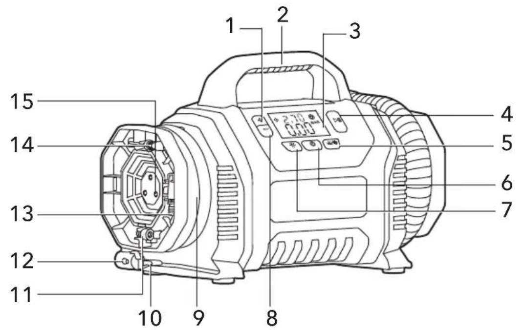
Overview (see figure A)
The numbering of the product features refers to the illustration of the machine on the graphics page.
1 BAR + Button
2 Handle
3 Digital Pressure Gauge
4 Start/Pause Button
5 Mode Button
6 Power Button
7 LED On/Off Button
8 BAR - Button
9 High Pressure Hose
10 Air-Chuck Clamp
11 Presta Valve Adapter
12 Air Chuck
13 Tapered Adapter
14 Sports Needle Adapter
15 LED Work Lights
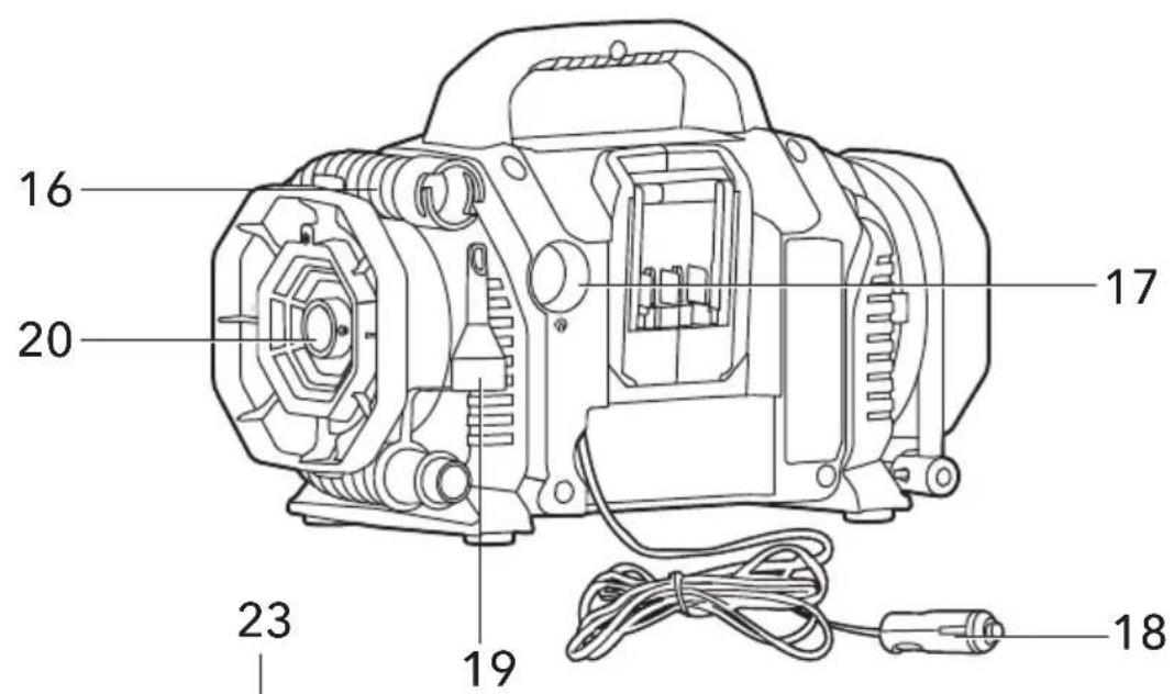
16 High Volume Hose
17 Air Intake
18 12V Vehicle Connector and Cord
19 Pinch Valve Adaptor
20 High Volume Air Output
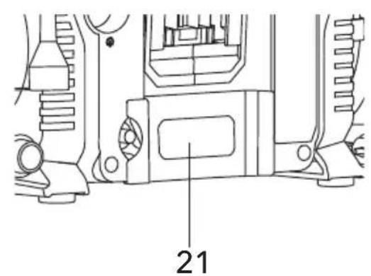
21 Vehicle Connector and Cord Cover
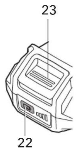
22 Battery Level Indicator Button
23 Battery-Release Button
Operating instructions

WARNING!
Remove the battery before carrying out any work on the power tool.
Before switching on the power tool
Unpack the dual function inflator and check that there are no missing or damaged parts.

NOTE
The batteries are not fully charged on delivery. Prior to initial operation, charge the batteries fully. Refer to the charger operating manual.
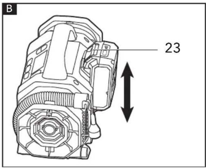
Inserting/replacing the battery
■ Press the charged battery into the power tool until it clicks into place.
■ To remove, press the release button (23) and pull out the battery. (see figure B)

CAUTION!
When the device is not in use, protect the battery contacts. Loose metal parts may short-circuit the contacts; explosion and fire hazard!
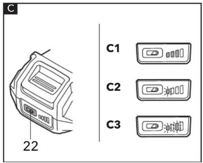
Battery level indicator (see figure C)
Press the battery level indicator button (22) to show the current battery level (see figure C1)

NOTE
- When the lowest level of the battery indicator starts flashing after pressing button, the battery is empty. (see figure C2)
- When 2 levels of the battery indicator start flashing after pressing button, the battery is not within the allowable operating temperature range. (see figure C3)
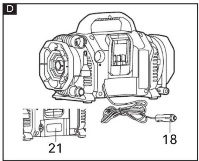
Car socket connection (see figure D)
■ As alternative to a battery pack, the car socket can be used as power supply.
■ Remove the vehicle connector and cord cover (21) from the back of the inflator.
■ Remove the car socket adapter (18) from the storage compartment.
■ Connect adapter to the car socket On/off.
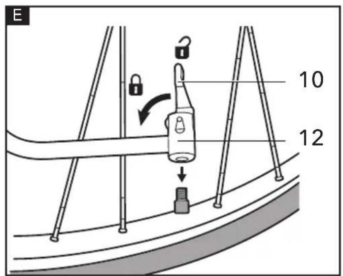
Inflating with the High-pressure hose (see figure E)
The air chuck (12) on the high-pressure hose can be used without adapters to inflate tires or other items that have a valve stem that fits the air-chuck opening.
■ Unlock the air chuck clamp (10)
■ Place the air chuck (12) on valve stem

NOTE
For Presta and Dunlop valves screw the adapter on the valve stem before placing the air chuck
■ Push the air chuck (12) down so that the threaded section of the valve stem is inside the air chuck
■ Lock the air chuck clamp(10)
■ See the instructions in the section of "Use the Digital Pressure Gauge in the High-Pressure Mode" in this manual for using the dual function inflator to start inflation.
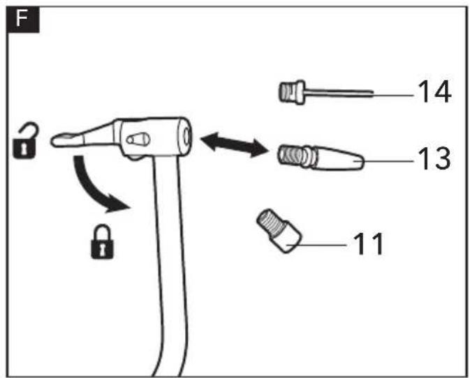
Inflating with the High-Pressure Hose and Adapters (see figure F)
The high-pressure hose can be used with the provided adapters to inflate a variety of items
Removing/installing adapters
■ Unlock the air chuck clamp (10)
■ Push the adapter into the air chuck (12) until it stops
■ Lock the air chuck clamp (10)
■ To remove the adapter, unlock the air chuck clamp (10) and remove the adapter from the air chuck (12).
Adapter Functions
■ The tapered adapter (13) -- Smaller air valves (such as floats and children's toys)
■ The sports needle (14) -- Sports balls or any other item that requires a sports needle.
■ The Presta valve adapter (11) -- Presta valve stems.
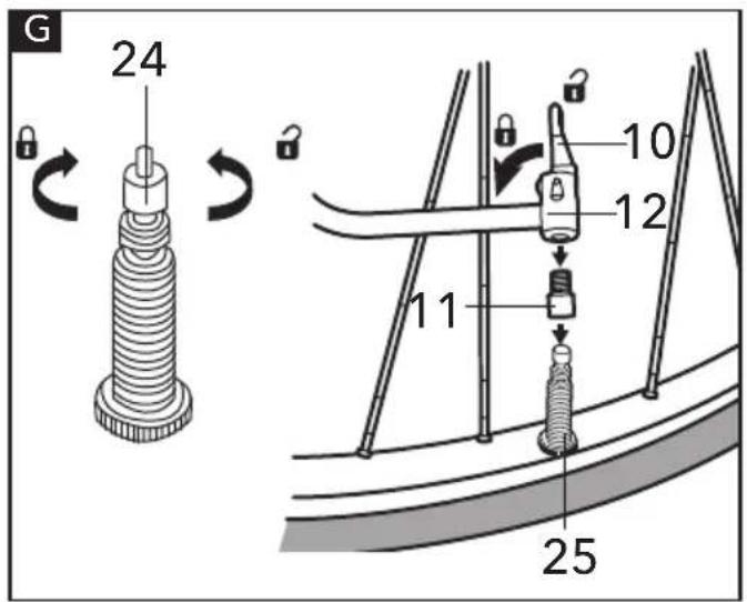
To use the presta valve adapter (see figure G)
■ Loosen the Presta valve locking nut (24).
■ Thread the Presta valve adapter (11) onto the Presta valve stem (25) of the tire.
■ Clamp the air chuck (12) onto the Presta valve adapter.
■ See the instructions in the section of "Use the Digital Pressure Gauge in the High Pressure Mode" in this manual for using the dual function inflator to start inflation.
■ After inflation, loosen and remove the air chuck (12) and the Presta valve adapter(11), then tighten the locking nut (24) of the Presta valve stem(25).
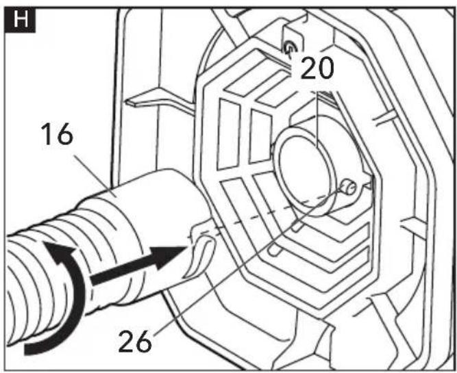
Inflating and Deflating with the High-Volume Hose (see figure H)
The high volume hose (16) is meant to be used for objects that hold large amounts of air, such as air mattresses, rafts and swimming pool floats.
■ Connect the high-volume hose (16) to the high volume air output (20). Align and
attach the slots in the hose to the pins (26), then turn the hose counter clockwise until it locks in place
■ Connect other end of the hose to the item to be inflated. Connect the hose directly or use the adapter attached to the hose.
■ See the instructions in the section of "Use the Digital Pressure Gauge in the High Volume Mode" in this manual for using the dual function inflator to start inflation.
■ After inflation, loosen and remove the high volume hose (16).
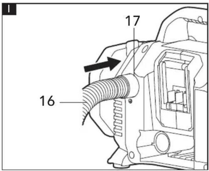
Deflating with the High-Volume Hose (see figure I)
■ Insert the high-volume hose (16) fully into the air intake (17).
■ Connect other end of the hose to the item to be deflated. Connect the hose directly or use the adapter attached to the hose.
- See the instructions in the section of "Use the Digital Pressure Gauge in the High-Volume Mode" in this manual for using the dual function inflator to start deflation.
■ After deflation, remove the high volume hose (16) from the air intake (17).
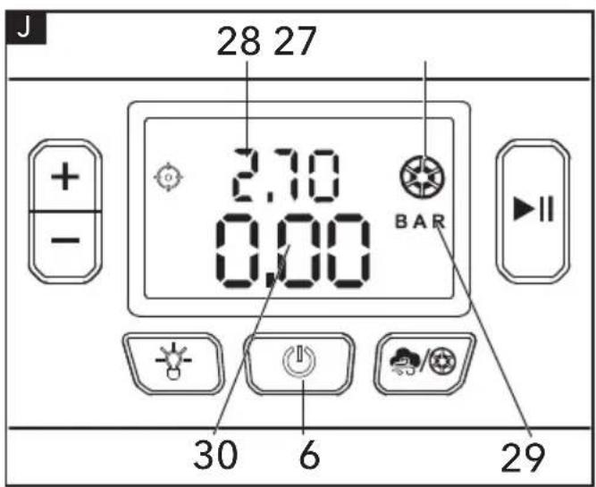
Using the Dual Function Inflator Use the Digital Pressure Gauge in the High-Pressure Mode (see figure J)
■ Press the power button (6) to turn the digital pressure gauge on. The working mode will default to the high-pressure mode (27). The dual function inflator will detect the current air pressure of the item (30).
■ Use the - and buttons + to set the target pressure (28).
NOTE
If the current pressure item to be inflated is greater than the target pressure, the dual function inflator will not begin inflation.
■ To select the desired unit of pressure, press the - and+ buttons simultaneously to scroll through the units (29) of BAR, KPA and PSI.
■ To start or pause the inflation, press the start/pause button (4).
■ The dual function inflator will shut off automatically when the target pressure (28) has been reached.
NOTE
After approx..5 minutes of inactivity the tool will automatically turn off.
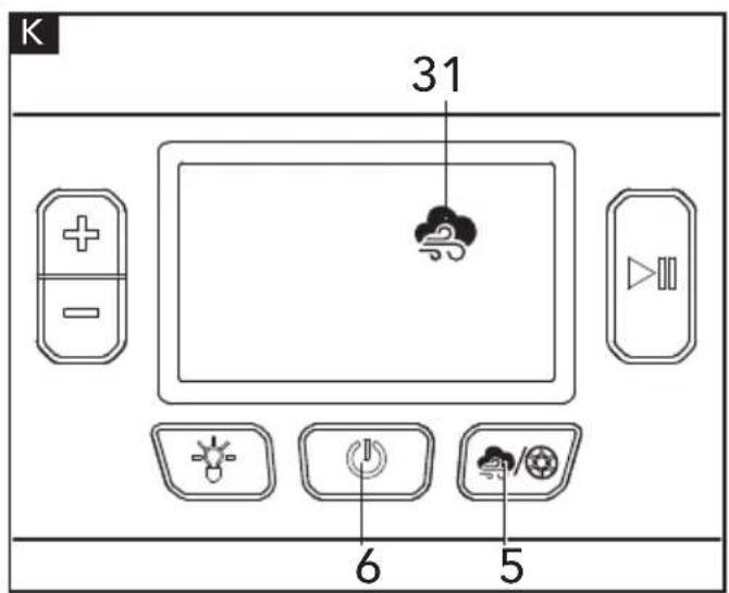
Use the Digital Pressure Gauge in the High-Volume Mode (see figure K)
■ Turn the digital pressure gauge on by pushing the power button (6). The working mode (27) will default to the high-pressure mode. Press the mode button (5) to switch to the high-volume mode (31).
■ To start or pause the inflation or deflation, press the start/pause button.
NOTE
Because the target pressure cannot be set in the high volume mode, there is no pressure related automatic shutoff.
LED Work Lights
■ To turn the LED work lights on, first power on the dual function inflator by pressing the power button, then press the LED On/Off Button(7).
■ Press the LED On/Off button (7) again to turn off the LED work lights.
Maintenance and care
WARNING!
Remove the battery before carrying out any work on the power tool.
Cleaning
■ Clean the power tool regularly. Frequency of cleaning is dependent on the material and duration of use.
■ Regularly blow out the housing interior and motor with dry compressed air.
Spare parts and accessories
For other accessories, see the manufacturer's catalogues. Exploded drawings and spare-part lists can be found on our homepage: www.flex-tools.com
Disposal information
WARNING!
Render redundant power tools unusable:
- Mains operated power tool by removing the power cord,
- Battery operated power tool by removing the battery.

EU countries only
Do not throw electric power tools into the household waste!
In accordance with the European Directive 2012/19/EU on Waste Electrical and Electronic
Equipment and transposition into national law used electric power tools must be collected separately and recycled in an environmentally friendly manner.
Raw material recovery instead of waste disposal.
Device, accessories and packaging should be recycled in an environmentally friendly manner. Plastic parts are identified for recycling according to material type.
WARNING!
Do not throw batteries into the household waste, fire or water. Do not open used batteries.
EU countries only:
In accordance with Directive 2006/66/EC defective or used batteries must be recycled.
NOTE
Please ask your dealer about disposal options!
C €-Declaration of Conformity
We declare under our sole responsibility that the product described under "Technical specifications" conforms to the following standards or normative documents:
EN 60335-1 in accordance with the regulations of the directives 2014/30/EU, 2006/42/EC, 2011/65/EU.
Responsible for technical documents:
Peter Lameli Klaus Peter Weinper Technical Head Head of Quality
Department (QD)
Declaration of Conformity
We as the manufacturer: FLEX Elektrowerkzeuge GmbH, Business address: Bahnhofstr. 15, 71711 Steinheim, Germany declare under our sole responsibility, that the product(s) described under „Technical specifications“ fulfills all the relevant provisions of The Supply of Machinery (Safety) Regulations S.I. 2008/1597 and also fulfills all the relevant provisions of the following UK Regulations: Electromagnetic Compatibility Regulations S.I. 2016/1091, The Restriction of the Use of Certain Hazardous Substances in Electrical and Electronic Equipment Regulations S.I. 2012/3032 and are manufactured in accordance with the following designated Standards: BS EN 60335-1:2019, BS EN 62233:2008, BS EN 55014-1:2017, BS EN 55014-2:2015, Place of declaration: Steinheim, Germany. Responsible person: Peter Lameli, Technical Director - FLEX-Elektrowerkzeuge GmbH
Contact details for Great Britain: FLEX Power Tools Limited, Unit 8 Anglo Office Park, Lincoln Road, HP 12, 3RH Buckinghamshire, United Kingdom.

19.05.2021
Exemption from liability
The manufacturer and his representative are not liable for any damage and lost profit due to interruption in business caused by the product or by an unusable product. The manufacturer and his representative are not liable for any damage which was caused by improper use of the power tool or by use of the power tool with products from other manufacturers.
Peter Lameli Klaus Peter Weinper Technical Head Head of Quality
Department (QD)
Technical Head Head of Quality
Department (QD)
Peter Lameli Klaus Peter Weinper Technical Head Head of Quality Department
(QD)
Peter Lameli Klaus Peter Weinper Technical Head Head of Quality
Department (QD)
Peter Lameli Klaus Peter Weinper Technical Head Head of Quality
Department (QD)
Peter Lameli Klaus Peter Weinper Technical Head Head of Quality Department
14 Adapter for sportsnål
15 LED arbeidslys
Peter Lameli Klaus Peter Weinper Technical Head Head of Quality Department
Peter Lameli Klaus Peter Weinper Technical Head Head of Quality Department
Peter Lameli Klaus Peter Weinper Technical Head Head of Quality
Department (QD)
Peter Lameli Klaus Peter Weinper Technical Head Head of Quality Department
Peter Lameli Klaus Peter Weinper Technical Head Head of Quality
Department (QD)
Peter Lameli Klaus Peter Weinper Technical Head Head of Quality Department
Peter Lameli Klaus Peter Weinper Technical Head Head of Quality Department
(QD)
Peter Lameli Klaus Peter Weinper Technical Head Head of Quality Department
Peter Lameli Klaus Peter Weinper Technical Head Head of Quality
Department (QD)
Peter Lameli Klaus Peter Weinper Technical Head Head of Quality Department
(QD)
Peter Lameli Klaus Peter Weinper Technical Head Head of Quality Department
Technical Head Head of Quality Department (QD)
Peter Lameli Klaus Peter Weinper Technical Head Head of Quality Department
Technical Head Head of Quality
Department (QD)
Technical Head Head of Quality
Department (QD)
Peter Lameli Klaus Peter Weinper Technical Head Head of Quality
Department (QD)
Peter Lameli Klaus Peter Weinper Technical Head Head of Quality Department
