SuperCross-Laser Compact - Measuring equipment Laserliner - Free user manual and instructions
Find the device manual for free SuperCross-Laser Compact Laserliner in PDF.

User questions about SuperCross-Laser Compact Laserliner
0 question about this device. Answer the ones you know or ask your own.
Ask a new question about this device
Download the instructions for your Measuring equipment in PDF format for free! Find your manual SuperCross-Laser Compact - Laserliner and take your electronic device back in hand. On this page are published all the documents necessary for the use of your device. SuperCross-Laser Compact by Laserliner.
USER MANUAL SuperCross-Laser Compact Laserliner
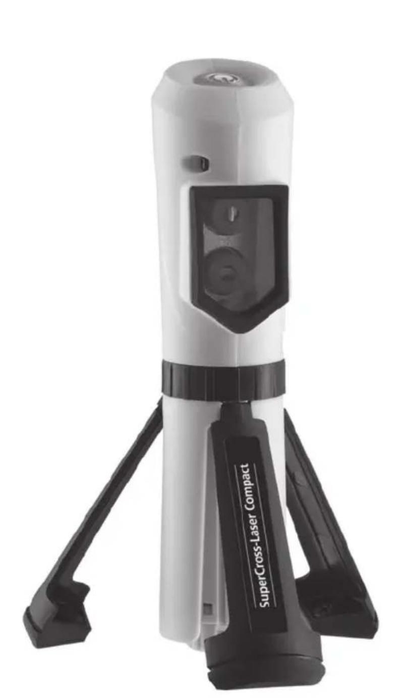
SuperCross-Laser Compact
natural_image
Exterior view of a SuperCross-Laser Compact device with black and white body (no visible text or symbols on the device itself)AUTOMATIC
LEVEL

1H 1V
5
Laserliner®
Innovation in Tools
| DE | 02 |
| GB | 06 |
| NL | 10 |
| DK | 14 |
| FR | 18 |
| ES | 22 |
| IT | 26 |
| PL | 30 |
| FI | 34 |
| PT | 38 |
| SE | 42 |
| NO | 46 |
| TR | 50 |
| RU | 54 |
| UA | 58 |
| CZ | 62 |
| EE | 66 |
| LV | 70 |
| LT | 74 |
| RO | 78 |
| BG | 82 |
| GR | 86 |
!
text_image
Warning sign with sunburst symbol inside triangle, indicating hazard or cautionRead the operating instructions and the enclosed brochure „Guarantee and additional notices“ completely. Follow the instructions they contain. Safely keep these documents for future reference.
Compact cross-line laser with 2 laser lines
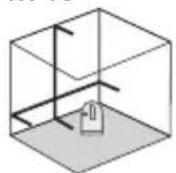
- Readily visible laser lines are outstanding for aligning tiles, wall studding, windows, doors, etc
- Simple to use by virtue of its magnetic-dampened pendulum system.
- Out-Of-Level: is indicated by optical signals when the unit is outside ist self-levelling range.
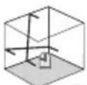
- The slope-mode feature is an extra that permits gradients to be laid out.
General safety instructions
text_image
Warning sign with sunburst symbol inside triangle, indicating hazard or cautionLaser radiation! Do not stare into the beam!
Class 2 laser < 1 mw · 635 nm EN 60825-1:2007-10
Caution: Do not look directly into the beam. Lasers must be kept out of reach of children. Never intentionally aim the device at people. This is a quality laser measuring device and is 100% factory adjusted within the stated tolerance. For reasons of product liability, we must also draw your attention to the following: Regularly check the calibration before use, after transport and after extended periods of storage. We also wish to point out that absolute calibration is only possible in a specialist workshop. Calibration by yourself is only approximate and the accuracy of the calibration will depend on the care with which you proceed.
Special product features
AUTOMATIC LEVEL
LEVEL
Automatic alignment of the device with a magnetically
dampened pendulum system. The device is brought into initial position and aligns itself autonomously.
Transport LOCK: The device is protected with a
pendelum lock during transport.
1H 1V
Number and direction of the lasers
1H = 1 horizontal laser line
1V = 1 vertical laser line
S = Slopefunction
SuperCross-Laser Compact
text_image
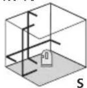
1 2 3 4 5 SuperCross Laser Compact1 ON/OFF button
2 Laser output windows
3 Transport retainer
4 Folding legs
5 Battery compartment
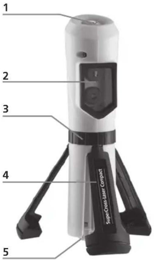
Transport retainer
text_image
Laserline SuperCranial 3 Open Locked!
Fold in the legs (4), switch off the laser (button 1) and lock the transport restraint (3) when the device is being transported or not in use. Then place the device in its soft-bag to protect it against damage.
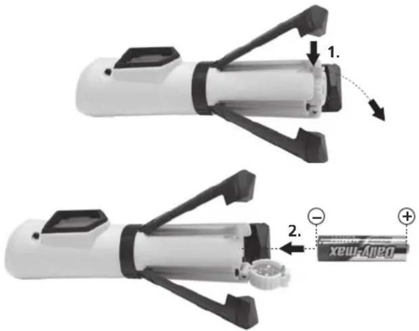
1 Insert battery
Open the battery compartment (5) and insert a battery.
text_image
Diagram showing two mechanical device components with labeled parts and a battery pack, illustrating assembly or disassembly steps.2 Horizontal and vertical levelling
Open the transport restraint and switch on the laser (button 1). The laser cross will appear. Now horizontal and/or vertical levelling work can be done.

The Out-Of-Level function must be activated in order to do horizontal and vertical levelling. It is activated by releasing the transport restraint. The Out-Of-Level function signals when the device is set up outside of its 4° automatic levelling range. If this is the case, the ON/OFF button will illuminate and the lasers will shut off. Place the device on a surface that is more level.
B Slope mode
Lock the transport restraint and switch on the laser (button 1). Now slopes can be laid out. IMPORTANT: This mode cannot be used to perform horizontal or vertical levelling because the laser lines are no longer automatically aligned.
4 EU directives and disposal
This device complies with all necessary standards for the free movement of goods within the EU.
This product is an electric device and must be collected separately for disposal according to the European Directive on waste electrical and electronic equipment.

Regularly check the calibration before use, after transport and after extended periods of storage.
Technical data
| Self-levelling range | ± 4° |
| Precision | ± 5 mm / 10 m |
| Operating range (depending on room illumination) | 20 m |
| Laser wavelength | 635 nm |
| Laser class / line laser output power | 2 / < 1 mW |
| Power supply / operating time | 1 x 1.5 V alkaline cell (type AA, LR6) / 5 hr. |
| Operating temperature | 0°C ... +50°C |
| Storage temperature | -10°C ... +70°C |
| Dimensions (W x H x D) | 35 x 153 x 36 mm |
| Weight (incl. battery) | 0,13 kg |
Subject to technical alterations 02.2010. Further safety and supplementary notices at: www.laserliner.com/info
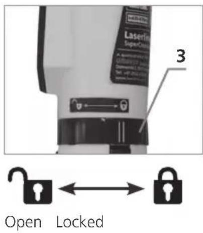
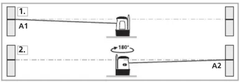
5 Preparing the calibration check
It is possible for you to check the calibration of the laser. To do this, position the device midway between 2 walls, which must be at least 5 metres apart. Do this by turning the unit on, thus releasing the transport restraint (cross laser on). See Section „Horizontal and vertical levelling“ about this.
- Mark point A1 on the wall.
- Turn the device through 180^ and mark point A2. You now have a horizontal reference between points A1 and A2.
text_image
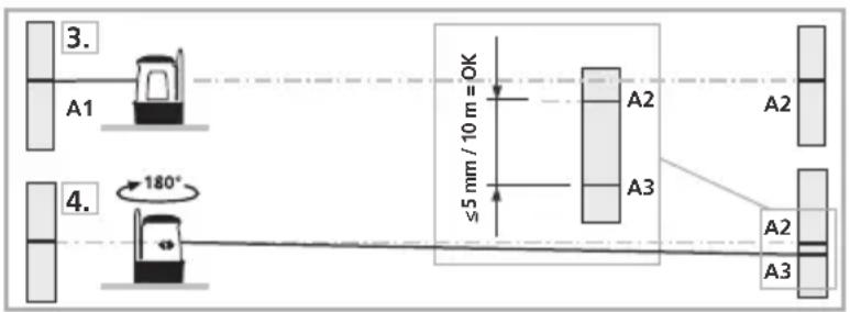
1. A1 2. 180° A26 Performing the calibration check
- Position the device as near as possible to the wall at the height of point A1.
- Turn the device through 180^ and mark point A3. The difference between points A2 and A3 is the tolerance.
text_image
3. A1 4. 180° ≤5 mm / 10 m = OK A2 A3 A2 A3
When A2 and A3 are more than 5 mm / 10 m apart, an adjustment is necessary. Contact your authorised dealer or else the UMAREX-LASERLINER Service Department.
Checking the vertical line: Position the device about 5 m from a wall. Fix a plumb bob with a line of 2.5 m length on the wall, making sure that the bob can swing freely. Switch on the device and align the vertical laser to the plumb line. The precision is within the specified tolerance if the deviation between the laser line and the plumb line is not greater than ± 1.5 mm.
Checking the horizontal line:
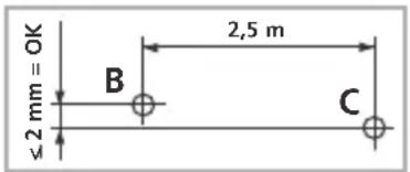
Position the device about 5 m from a wall and switch on the cross laser. Mark point B on the wall. Turn the laser cross approx. 2.5 m to the right and mark point C.
text_image
≤2 mm = OK B 2,5 m CCheck whether the horizontal line from point C is level with point B to within ± 2 mm. Repeat the process by turning the laser to the left.
!
text_image
Warning sign with sunburst symbol inside triangle, indicating hazard or cautiontext_image
Diagram showing two battery components with labeled parts and a battery pack, illustrating mechanical assembly or disassembly.text_image
3. A1 ≤ 5 mm / 10 m = OK 4. 180° A2 A3 A2 A3
text_image
Warning sign with sunburst symbol inside triangle, indicating hazard or cautiontext_image
LaserJet SuperControl 3Åbn Lås
!
text_image
3. A1 4. 180° ≤ 5 mm / 10 m = OK A2 A3 A2 A2 A3
text_image
Warning sign with triangular shape containing a central explosion or burst symboltext_image
LaserJet SuperCond 3Ouvrir Fermer
!
text_image
Diagram showing two mechanical device configurations with labeled parts and a battery pack, including directional arrows and polarity indicators.text_image
Warning sign with sunburst symbol inside triangle, indicating hazard or alerttext_image
3. A1 4. 180° ≤ 5 mm / 10 m = OK A2 A3 A2 A3
text_image
Warning sign with triangular frame and central explosion symboltext_image
Warning sign with triangular frame and central explosion symboltext_image
Diagram showing two mechanical device configurations with labeled parts and a battery model, including directional arrows and polarity indicators.text_image
Warning sign with sunburst symbol inside triangle, indicating hazard or cautiontext_image
Diagram showing two mechanical devices with labeled parts and a battery pack, illustrating assembly or disassembly steps.text_image
Warning sign with triangular frame and central sunburst symbolRadiação laser! ¡No mire al rayo láser! Láser classe 2 < 1 mW · 635 nm EN 60825-1:2007-10
text_image
Diagram showing two mechanical devices with labeled parts and a battery pack, illustrating assembly or disassembly steps.text_image
Warning sign with triangular triangle and central explosion symboltext_image
Diagram showing two mechanical device components with labeled parts and a battery pack, illustrating assembly or disassembly steps.text_image
Warning sign with sunburst symbol inside triangle, indicating hazard or cautionLaserstråling! Ikke se inn i strålen! Laser klasse 2 < 1 mW · 635 nm EN 60825-1:2007-10
text_image
Diagram showing two mechanical device configurations with labeled parts and a battery pack, illustrating assembly or disassembly steps.text_image
Warning sign with sunburst symbol inside triangle, indicating hazard or cautiontext_image
Warning sign with sunburst symbol inside triangle, indicating hazard or cautionЛазерное излучение!
text_image
Diagram showing two mechanical device components with labeled parts and a battery pack, illustrating assembly or disassembly steps.text_image
Warning sign with sunburst symbol inside triangle, indicating hazard or alerttext_image
Warning sign with sunburst symbol inside triangle, indicating hazard or cautionLASEROVÉ ZÁŘENÍ!
NEDÍVEJTE SE DO
PAPRSKU!
LASER TRÍDY 2
< 1 MW · 635 NM
EN 60825-1:2007-10
text_image
Warning sign with sunburst symbol inside triangle, indicating hazard or cautionLASERIKIIRGUS -
MITTE VAADATA
LASERIKIIRT!
LASERIKLASS 2
< 1 mW · 635 nm
EN 60825-1:2007-10
text_image
Diagram showing two mechanical devices with labeled components and a battery pack, illustrating assembly or disassembly steps.text_image
Warning sign with triangular frame and central explosion symbolLÄZERSTAROJUMS! NESKATİTIES TIEŠI STARÄ!
- LÃZERA KLASE
< 1 mW · 635 nm
EN 60825-1:2007-10
text_image
Warning sign with black triangular triangle and central explosion symbolLAZERIO SPINDULYS – NEŽIŪRĖKITE J LAZERIO SPINDULJ!
LAZERIO KLASÉ 2
< 1 MW · 635 NM
EN 60825-1:2007-10
text_image
Diagram showing two mechanical device components with labeled parts and a battery pack, illustrating assembly or disassembly steps.text_image
Warning sign with sunburst symbol inside triangle, indicating hazard or cautionRADIATIE LASER! NU SE VA PRIVI ÎN RAZA! LASER CATEGORIA 2 < 1 mW · 635 nm EN 60825-1:2007-10
text_image
Diagram showing two mechanical devices with labeled components and a battery pack, illustrating assembly or disassembly steps.text_image
Warning sign with sunburst symbol inside triangle, indicating hazard or alerttext_image
Diagram showing two mechanical devices with labeled components and a battery pack, illustrating assembly or disassembly steps.text_image
Warning sign with triangular frame and central explosion symbolnatural_image
Interior view of an art gallery with framed paintings on walls and a telescope on a pedestal (no text or symbols visible)SERVICE

Umarex GmbH & Co KG
-Laserliner-