ThermoCamera Pocket - Measuring equipment Laserliner - Free user manual and instructions
Find the device manual for free ThermoCamera Pocket Laserliner in PDF.

| Product type | Thermal camera |
| Brand | Laserliner |
| Model | ThermoCamera Pocket |
| Category | Measuring equipment |
| Sensor type | Uncooled microbolometer |
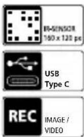
| Infrared resolution | 160 x 120 pixels |
| Display resolution | 320 x 240 pixels |
| Field of view (FOV) | 42° x 32° |
| Thermal sensitivity (NETD) | 0.05 °C (50 mK) @ 30 °C |
| Measurement range | -20 °C to 150 °C / 0 °C to 550 °C |
| Accuracy | ±2 °C or 2 % of measured value |
| Battery life | Approximately 4 hours |
| Power supply | Li-ion battery 3.7 V / 1.5 Ah / 5.55 Wh |
| Dimensions (L x H x D) | 90 x 25 x 85 mm |
| Weight | 168 g (battery included) |
| Memory | micro SD card up to 128 GB |
| Connections | USB Type-C |
| Image modes | IR Thermal, Visible, MIX (Auto Fusion) |
| Integrated flashlight | Yes |
| PC software | Windows 10/11, free download |
| Care and cleaning | Slightly damp cloth, no solvents |
| Safety | EMC compliant, do not use near high voltages |
| Recommended calibration | Once a year |
Frequently Asked Questions - ThermoCamera Pocket Laserliner
User questions about ThermoCamera Pocket Laserliner
0 question about this device. Answer the ones you know or ask your own.
Ask a new question about this device
Download the instructions for your Measuring equipment in PDF format for free! Find your manual ThermoCamera Pocket - Laserliner and take your electronic device back in hand. On this page are published all the documents necessary for the use of your device. ThermoCamera Pocket by Laserliner.
USER MANUAL ThermoCamera Pocket Laserliner
Laserliner
!
natural_image
Thermal imaging view showing heat distribution with bright yellow-orange hotspots against a dark blue background (no text or symbols visible)16 Fehlerdiagnose
https://packd.li/ll/ata/in
Completely read through the operating instructions, the „Warranty and Additional Information” booklet as well as the latest information under the internet link at the end of these instructions. Follow the instructions they contain. These documents must be kept in a safe place and passed on together with the product.
Intended use
This thermal imaging camera provides non-contact temperature measurement of surfaces. The device evaluates the radiation in the infrared wavelength via an integral, uncooled microbolometer. The imaging technology of the sensor provides a visual image of the temperatures surrounding the inspected object. Optimum visualisation of the temperature differences is achieved by colour coding the different measured temperatures in a thermogram using a false colour display. The additional digital camera allows photographs to be taken of the inspected area for documentation purposes. Amongst other things, the product is suitable for detecting thermal bridges and failed insulation in buildings, analysing heating systems, locating overheated components, cables and fuses, and identifying defective solar cells in PV modules. The analysis can be carried out on infrared, digital or MIX images (Auto Fusion). The MIX image provides an extremely easy to interpret and comprehensive representation of the temperature profiles by combining digital and infrared images. Measured data can be saved to an exchangeable SD card and transferred to a PC via the USB-C interface. The CustomApps function offers optimised default parameter settings for an extremely wide range of uses. This allows thermal imaging camera applications to be set quickly and safely for each specific use.
General safety instructions
- The product must only be used in accordance with its intended purpose and within the scope of the specifications.
- This product and its accessories are not toys. Keep out of reach of children.
- Modifications or changes to the product are not permitted, this will otherwise invalidate the approval and safety specifications.
- Do not expose the product to mechanical stress, extreme temperatures or significant vibration.
- The product may no longer by used if one or more of its functions fails, or if the housing or connections are damaged.
- When using the product outdoors, make sure that the weather conditions are appropriate and/or that suitable protection measures are taken.
- Do not touch the optical lenses with your hands.
Safety instructions
Dealing with electromagnetic radiation
- The measuring device complies with electromagnetic compatibility regulations and limit values in accordance with EMC-Directive 2014/30/EU.
- Local operating restrictions – for example, in hospitals, aircraft, petrol stations or in the vicinity of people with pacemakers – may apply. Electronic devices can potentially cause hazards or interference or be subject to hazards or interference.
- The measuring accuracy may be affected when working close to high voltages or high electromagnetic alternating fields.
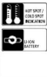
1 ON/OFF / temperature mode / back button
2 2,8" TFT colour display
3 Shutter / button left/up
4 button confirm/cancel
5 CustomApps / button right/down
6 Trigger (image capture) / back button
7 Mounting eyelet
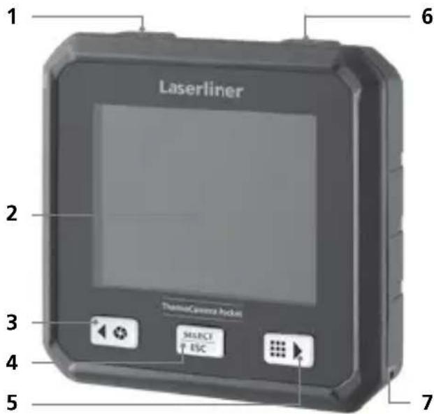
8 Flashlight
9 Digital camera
10 Infrared camera lens
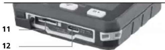
11 Micro-SD card
12 USB-C interface
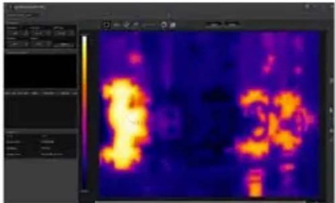
heatmap
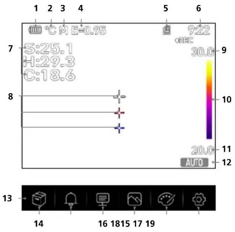
| Position | Value | |---|---| | 1 | 9.22 | | 5 | 30.0 | | 6 | 11 | | 7 | 25.1 | | 8 | 29.3 | | 9 | 18.6 | | 10 | 10 | | 11 | 11 | | 12 | 12 | | 13 | 14 | | 14 | 16 | | 15 | 18 | | 16 | 19 |
The hot and cold spots dynamically indicate the temperature extremes in an image capture.
1 Battery charge indicator
2 Temperature unit
3 Unit of distance
4 Set emissivity
5 Micro-SD card inserted
6 Time
7 Temperature:
S = mid-point
H = hot spot (max. temp. °C)
C = cold spot (min. temp. °C)
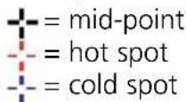
8 Marking:
9 Temperature Max.
10 Colour spectrum with temperature range
11 Temperature Min.
12 Select temperature mode
13 Main menu
14 Gallery
15 Set alarm above/below
16 Set parameter
17 Set image
18 Change colour pallet
19 General and measurement-specific settings
1 Inserting micro-SD card
To insert a micro-SD card, first open the rubber cover and then insert the memory card as illustrated.
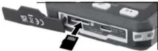
The device must be switched off before removing the micro-SD.
2 Use of lithium-ion rechargeable battery
- The battery must only be charged using the supplied USB charging cable and a USB-compatible power adapter with 5V and a minimum of 2.4A. Using any other power pack/charger will invalidate the warranty.
- Use the power supply/charger unit only in closed rooms; do not expose to moisture or rain otherwise risk of electric shock.
- Disconnect the power pack/charger from the mains when the device is not in use.
- When opening the device, qualified professionals must follow the disassembly instructions (link provided at the end of this section) and make sure there are no conductive objects in the vicinity of the battery contacts. Short-circuiting of these contacts can cause burn injuries or fire.
- Do not open the rechargeable battery. This could cause short-circuits.
- Connect the power supply unit to the mains and the connecting socket
- Charge the device's battery completely prior to use.
- When charging begins, a battery icon appears on the display, with bars gradually filling in.
- Charging is complete when the battery icon is fully filled with bars.
- If the battery has a weak charge, the battery icon is shown in red and a written warning appears in the display.

The device has a replaceable battery. Contact your distributor or the UMAREX-LASERLINER service department. The battery disassembly instructions can be found at: https://packd.li/ll/ata/ri
3 ON / OFF

ON
OFF
This thermal imaging camera is a precision device which can identify extremely small temperature differentials using highly sensitive infrared sensors. For applications where extremely accurate temperature readings for the measurement results are required, the thermal imaging camera must be operational for at least ten minutes every time either it is switched on or the temperature range
is changed in order to adjust the integral sensors to their operating temperature. Rapidly changing device or ambient temperatures, air flows, or external temperature sources are to be avoided.
4 Main menu
General and measurement-specific settings can be made in the main menu.

Gallery: You can access and manage all of the images captured with the thermal imaging camera in the media gallery.

Alarm: Set the alarm above and below the specified temperature level.

Parameter: Before each use, check the relevant parameters for infrared measurement or adjust them to the specific measuring situation to ensure accurate measurements. In doing so, please pay particular attention to the general parameters with respect to the emissivity coefficient, distance to target and ambient conditions.

Image mode: Select image mode from IR Thermal, MIX Image (Auto Fusion) and Visible image.

Colour palettes: Several colour palettes are available to display the infrared temperatures.

Settings: Set language, temperature units, date, time, etc., select CustomApps, automatic switch off and display information about the device.

Alarm: Below MIN / above MAX alarm

The alarm threshold values above and below the specified temperature levels can be set in this menu. Instructions for activating the alarm are provided in Section 11.3.

Parameter: Ambient temperature

Influences measurements taken with the thermal imaging camera are affected by the ambient temperature. This parameter compensates the influence of the ambient temperature on the measurement. This can be set between -10 °C and 50 °C.

Parameter: Reflection temperature

Infrared measurements of specific objects can be affected by reflection from other objects nearby or even from the ambient air because the measured object cannot be fully isolated. The reflection temperature setting can help compensate for the interference. The reflection
temperature is generally the same as the ambient temperature.
However, if larger objects with significantly different temperatures (approx. > 20 °C) are in close proximity to the measured area, its effects must be taken into account. For this purpose, follow these steps:
- Set emissivity coefficient to 1.0
- Aim the camera in the opposite direction of the actual measured object
- Determine the average temperature
- Set the average temperature as the reflection temperature
Laserliner
6.2 Parameter: Relative humidity

High humidity can lead to the lens of the thermal imaging camera misting over which means the infrared radiation is not fully received. The infrared radiation is absorbed on the way to the lens by the atmosphere and distributed by the water vapour suspended in the air, amongst other things (relative humidity). These influences should be taken into consideration, particularly when the distance to the measured object exceeds around 30 m. This can have a negative influence on the measuring accuracy. The parameter can be set from 10 % to 100 % to compensate for the influence of the relative humidity. Thick fog can also affect the measurement as the water droplets in the transmission path allow less infrared radiation through.
6.3 Parameter: Temp. Compensation

The temperature compensation can be set between -5.0 °C and +5.0 °C.
6.4 Parameter: Distance

Air contains many different substances which can absorb infrared rays. The infrared radiation from the inspected object therefore decreases as the distance increases. At distances greater than 10 metres, the atmospheric influences of the air must always be taken into account.
The distance can be set between 0 and 2,000 m.
6.5 Parameter: Emissivity

The level of infrared emissions given off by everything depends on the specific material and surface. This factor is determined by the emissivity coefficient (0.01 ... 1.0). For accurate measurements, it is absolutely essential that the emissivity coefficient is set first. The emissivity coefficient can be custom set or selected based on the predefined emissivity coefficients from the material list.

A simplified table for the emissivity coefficient is available from the Measurement Settings menu under Emissivity Coefficient.

Before each use, check the settings for infrared measurement and adjust them to the respective measuring situation to ensure accurate measurements. Pay particular attention to the general parameters for the emissivity coefficient and the reflection temperature.
Emissivity table (reference values with tolerances)
| Metals | |||||
| Alloy A3003 | Iron | Steel | |||
| Oxidised | 0.20 | Oxidised | 0.75 | Alloy (8% nickel, 18% chromium) | 0.35 |
| Roughened | 0.20 | With rust | 0.60 | Galvanised | 0.28 |
| Aluminium | Iron, cast | Oxidised | 0.80 | ||
| Oxidised | 0.30 | Non-oxidised | 0.20 | Heavily oxidised | 0.88 |
| Polished | 0.05 | Molten mass | 0.25 | Freshly rolled | 0.24 |
| Rough, flat surface | 0.96 | ||||
| Rusty, red | 0.69 | ||||
| Brass | Iron, forged | Sheet, nickel plated | 0.11 | ||
| Polished | 0.30 | Matt | 0.90 | Sheet, rolled | 0.56 |
| Oxidised | 0.50 | Lead | Stainless steel | 0.45 | |
| Chromium oxide | 0.81 | Rough | 0.40 | Zinc | |
| Copper | Platinum | Oxidised | 0.10 | ||
| Oxidised | 0.72 | Black | 0.90 | ||
| Copperoxide | 0.78 | ||||
| Inconel | Steel | ||||
| Oxidised | 0.83 | Cold rolled | 0.80 | ||
| Electropolished | 0.15 | Ground plate | 0.50 | ||
| Polished plate | 0.10 | ||||
Nonmetals
| Asbestos 0.93 | Grit 0.95 | Plastic | |||||
| Asphalt 0.95 | Gypsum | 0.88 | Translucent | 0.95 | |||
| Basalt 0.70 | Gypsum cardboard | 0.95 | PE, P, PVC | 0.94 | |||
| Brick, red 0.93 | Heat sink | Quartz glass | 0.93 | ||||
| Carborundum 0.90 | Black, anodized | 0.98 | Rubber | ||||
| Cement 0.95 | Human skin | 0.98 | Hard | 0.94 | |||
| Ceramics 0.95 | Ice | Soft, grey | 0.89 | ||||
| China Brilliant white With glaze | 0.73 0.92 | Clear With heavy frost | 0.97 0.98 | Sand | 0.95 | ||
| Laminate | 0.90 | Screed | 0.93 | ||||
| Lime | 0.35 | Snow | 0.80 | ||||
| Clay 0.95 | Lime malm brick | 0.95 | Soil | 0.94 | |||
| Coal Non-oxidised | 0.85 | Limestone | 0.98 | Tar | 0.82 | ||
| Marble | Tar paper 0.92 | ||||||
| Concrete, plaster, mortar | 0.93 | Black, dull finish Greyish, polished | 0.94 0.93 | Transformer paint | 0.94 | ||
| Cotton 0.77 | Masonry 0.93 | Wallpaper, light-co-loured | 0.89 | ||||
| Earthenware, matt 0.93 | Paint | Water | 0.93 | ||||
| Fabric 0.95 | Black, matt Heat-resistant White | 0.97 0.92 0.90 | Wood Untreated Beech, planed | 0.88 0.94 | |||
| Glass 0.90 | |||||||
| Glass wool 0.95 | |||||||
| Graphite 0.75 | Paper | ||||||
| Gravel 0.95 | All colours | 0.96 | |||||
Laserliner
7.0 Image: IR Thermal

Various image display modes are available: IR Thermal, Visible Image, MIX Image (Auto Fusion). In IR Thermal mode, only the infrared image is shown.
7.1 Image: Visible image

In Visible image mode, the digital image is displayed.
7.2 Image: MIX Image (Auto Fusion)

In MIX Image mode, the digital image and infrared image are overlaid using edge detection and detail enhancement. This allows the location of the relevant infrared areas to be quickly and precisely identified. The temperature in the central area is compared to the digital image. The mix ratio between the infrared image and the digital image can be adjusted manually. The detail of the overlaid area occupies approximately half the display area and is placed centrally but can be moved to a specific position using the touchscreen.
8.0 Set palette

There are eight standard palettes for displaying the recorded infrared temperatures. The choice of palette allows the false colour display of the infrared images displayed or taken to be modified. The measured temperatures are adjusted within the current image section and displayed in the respective colour space. The bargraph for the respective minimum/maximum temperatures serves as a reference for the temperature and colour mapping. The standard palettes provide a smooth and linear reproduction.
Iron
Rainbow
FeatherHot/Co
9 Temperature mode: Automatic, Manual and Histogram mode
AUTO In Automatic mode, the measured temperature range of the infrared image and the resulting distribution of the colour spectrum are dynamically adjusted. The colour spectrum of the measured infrared image is determined by the temperature range and colour scale. The colour distribution of the infrared image is automatically and dynamically adjusted in the bargraph based on the measured min./max. values.
MANUAL In manual settings mode, the temperature range is no longer set automatically based on the measured min./max. values but rather determined on the basis of manual values.
HG In Histogram mode, the colour distribution of the infrared image is adjusted in the same way as in Automatic mode. In addition, a statistical analysis of the temperature distribution in the infrared image (histogram) stabilises the min.max. values. If the temperatures vary significantly, this stabilises the view from one image to the next, e.g. when measuring moving objects.

The min/max values last measured are taken as the default setting every time the temperature range is switched from histogram (HG) to manual (MANUAL). Procedure when measuring in Manual temperature mode. For quick localisation and inspection of the relevant measuring positions, view the measured object in Automatic mode and determine the optimum measuring position in which the min/max temperature range approximately corresponds to the required temperature range. Once the min/max values have stabilised, select Manual mode without changing position to transfer the current values as a default setting using button (1).
10.0 Device settings: USB Mode (PC connection or PC camera)
The data recorded by the thermal imaging camera can be transferred to a PC in USB mode. To allow several people to view the image on the camera at the same time, the PC can be used for live transmission. The USB drive must be correctly removed from the PC after use to avoid read errors on the PC.
10.1 Device settings: Flashlight
The integrated torch makes it easier to see in dark areas, such as unfinished buildings without power or lighting, attic spaces, behind curtains, under stairs and in crawl spaces.
10.2 Device settings: Brightness
Screen brightness can be adjusted using the arrow keys.
10.3 Device settings: Date/Time
The time and date can be adjusted using the arrow buttons.
10.4 Device settings: Language
The preferred language can be set in this menu.
10.5 Device settings: Auto Power Off
The device switches off automatically after the preset time interval. The timer resets when any button is pressed.
10.6 Device settings: About
This menu provides information on the product.
11.0 Measure Settings: Distance unit
The unit of distance can be set in this menu.
Laserliner
11.1 Measure Settings: Temperature unit
The unit of temperature can be set in this menu.
11.2 Measure Settings: Temperature range
The default setting for the temperature range can be selected in this menu. Choose between two ranges: -20 - +150 °C (optimum for indoor and outdoor thermal imaging of buildings) 0 - +550 °C (optimum for industrial applications).
11.3 Measure Settings: Alarm mode (visual)
The upper and low alarm levels can be activated in the Alarm Mode menu. The upper and lower alarm levels must be activated to use the Alarm Range function. The Alarm Range is defined by the threshold values for the upper and lower alarm levels. The visual alarm highlights the mid-point, and hot and cold spots as well as their respective temperatures when a temperature is detected within the set limits. For example when the temperature is 35 °C and the upper alarm is set at 40 °C and the lower alarm at 30 °C .
11.4 Measure Settings: Image Align
The digital image and infrared image can be aligned to each other using the arrow keys. Use button 6 to toggle between the X and Y axes.
12 Reset
Selecting the "Format storage" option will delete all contents on the SD card currently inserted. All settings can be reset to factory defaults by selecting "Factory settings". We recommend formatting the SD card directly on a PC using FAT32 Format.

Warning: This will erase all recorded data and settings, including media gallery contents.
13.0 Camera: Shutter
In addition to the basic settings of the measuring device, the shutter function is an essential component for accurate thermography results. The image can be calibrated either manually or automatically. Manual calibration is activated by holding down button (3). Automatic calibration is performed, after a period of time, to keep the IR image sensor cyclically in the highest accuracy range.
13.1 Camera: Image and Video Capture
Pressing the shutter button freezes the image and opens the save menu with editing and comment functions. The editor including the keyboard is opened via the text note icon and closed via the checkmark icon. For video recording, hold the shutter button for at least 2 seconds; stop and save by pressing again.
13.2 Camera: Media gallery
Image captures are saved as JPG and HIR files in the media gallery, and also include the radiometric measurement data as well as the infrared/digital image. You can access, play and manage all of the images and videos recorded with the thermal imaging camera in the media gallery.
14.0 CustomApps: Menu
One-click configuration allows the device to be configured quickly using the CustomApp function for a wide range of standard applications, even with extensive parameter setups. CustomApps can be accessed by pressing the menu hot key for 1 seconds or from the
Settings menu. Further information on CustomApps is available here: https://packd.li/ll/ca2/ap/wi
14.1 CustomApps: Factory Settings
All parameters are reset to the default factory settings, the language settings remain the same. Due to the number of parameters and the subsequent possibility of entering incorrect information, it is advisable to reset the camera to the default settings before every important measurement. This allows parameters to be entered from a known starting point.
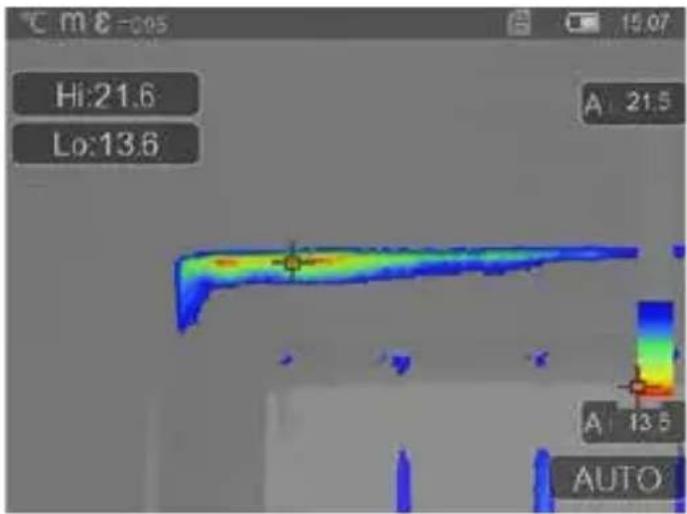
14.2 CustomApps: ThermalInsulation-Control
line
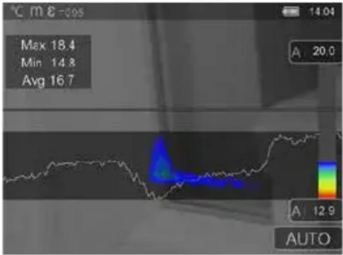
| Statistic | Value | | --------- | ----- | | Max | 18.4 | | Min | 14.8 | | Avg | 16.7 | | A | 20.0 | | A | 12.9 | | AUTO | |Thermal Insulation-Control is suitable for checking thermal insulation and analysing energy losses in indoor spaces. Cold building surfaces which can lead to energy losses are shown as blue to black, mid-warm surfaces in green to yellow, and warm surfaces in red to white. The horizontal line makes it easier to identify slight insulation problems and provides an overview of the energy efficiency of the area of the building under investigation. Typical weak spots are usually located on building façades but can also be around external doors, windowsills, pipework, and in heated cellars.
14.3 CustomApps: FloorHeating-Control
FloorHeating-Control provides visualisation of cable routing, thermal distribution and possible air inclusions. It allows you to check that an existing or recently installed underfloor heating system is heating up evenly. The thermal imaging camera provides information on the floor surface temperature which is also an important indicator of the heating system's efficiency.
14.4 CustomApps: LeakageControl
LeakageControl identifies cold spots where moisture can condense and damage from leaks may occur. These are the points in a building which transfer heat from inside to outside in a short space of time and thus cool more quickly than the surrounding areas. Early identification and treatment of these areas prevent subsequent mildew.
ColdView-Inspection is suitable for detailed examination of cold areas. Problem points such as thermal bridges, cold air flows or air leakages, such as around window frames or doors, can be identified quickly and accurately. The MIX image overlays the digital image on the coldest 20 % of the temperature range captured on site. The condensed colour palette provides an optimum visualisation of the precise extreme temperature points. A standard colour palette can be used for subsequent temperature measurement of the extremes in order to produce a balanced colour image for measurement and evaluation. The centre point (P1) provides direct temperature measurement.
14.6 CustomApps: Warmstellen-Inspektion
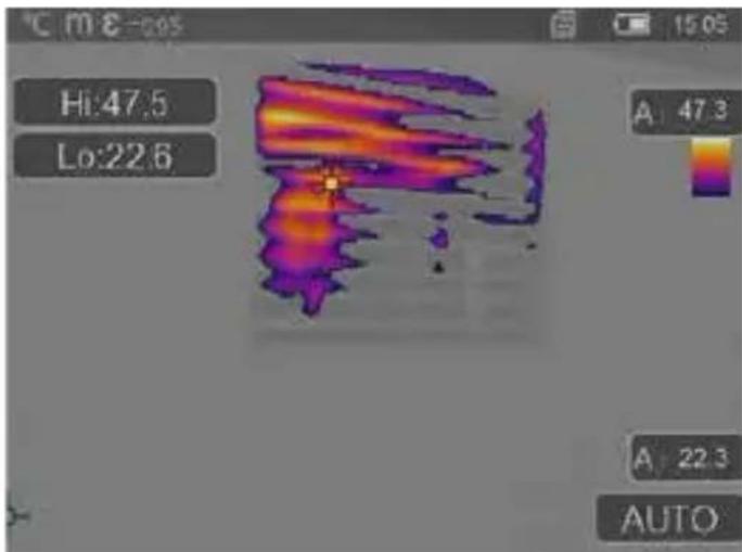
HotView-Inspection is suitable for detailed examination of hot areas and determination of points with predominantly high temperatures. These include heating pipes, fuses and electrical connections. The MIX image overlays the digital image on the warmest 20 % of the temperature range captured on site. The condensed colour palette provides an optimum visualisation of the precise extreme temperature points. A standard colour palette can be used for subsequent temperature measurement of the extremes in order to produce a balanced colour image for measurement and evaluation. The centre point (P1) provides direct temperature measurement.
14.7 CustomApps: OverHeating-Alarm
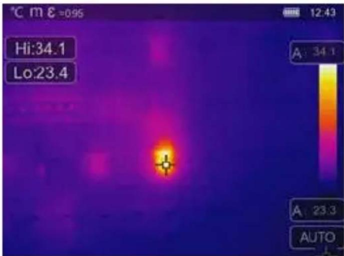
can also be identified, for example, brakes on lorries. To ensure stable measuring conditions, the best option is to use a tripod.
OverHeating-Alarm provides point measurement of temperatures and emits an acoustic alarm when the upper threshold value is exceeded. The setting for the threshold value is displayed once the CustomApp has been opened allowing you to set the threshold value (section 5, Setting the alarm) to suit the application. All other parameters have already been set. Check the function on a hot item before measuring the temperature. Applications include checking temperature threshold values for heating/air conditioning systems, for quality control in production areas, and determining overheated areas in buildings. Overheated electrical, mechanical or automotive components
14.8 CustomApps: Cold-Alarm
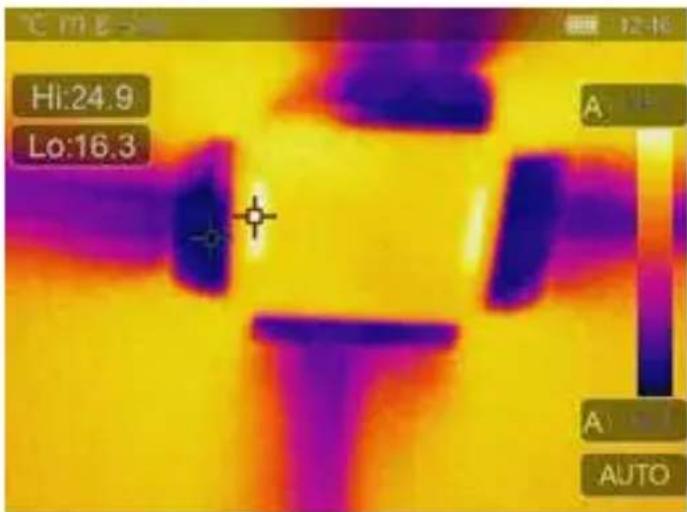
option is to use a tripod.
Cold-Alarm provides point measurement of temperatures and emits an acoustic alarm when the value falls below the lower threshold value. The setting for the threshold value is displayed once the CustomApp has been opened allowing you to set the threshold value (section 5, Setting the alarm) to suit the application. All other parameters have already been set. Check the function on a cold item before measuring the temperature. Applications include quick identification of areas in buildings where the temperature is too low, monitoring inlet temperatures and checking air conditioning systems, freezers and refrigerated warehouses. To ensure stable measuring conditions, the best
15 Software for Windows desktop PC
The software available online allows the recorded data to be transferred to a PC and used for further processing and documentation. Download the software and follow the installation instructions.
https://packd.li/ll/qrplus/ap/wi

It is not necessary to install a driver. The software operates under Windows 10 and 11.
2.
natural_image
Thermal imaging view showing heat signatures with no visible text or symbols16 Fault diagnosis
If problems occur when using the thermal imaging camera, take the following steps as shown in the table below. Should the problem persist, please contact the UMAREX Laserliner service department.
Error
device does not start Incorrect temperature display Incorrect image display Blurred image display device switches off suddenly
Reason
battery depleted Parameter setting unclear R Parameter setting unclear Outside optim. focus range no power
Solution
charge battery ry reset Reset via factory reset Adjust object distance charge battery
Information on maintenance and care
Clean all components with a damp cloth and do not use cleaning agents, scouring agents and solvents. Store the device in a clean and dry place.
Calibration
The measuring device must be calibrated and tested on a regular basis to ensure it is accurate and working properly. We recommend carrying out calibration once a year. Contact your distributor or the UMAREX-LASERLINER service department.
Technical Data (Subject to technical alterations. Rev25W23)
| Sensor type uncooled microbolometer | |
| Infrared temperature resolution | 160 x 120 pixels |
| Resolution display 320 x 240 pixels | |
| Field of view (FOV) 42° x 32° | |
| Spatial resolution (IFOV) 4,60 mrad | |
| Frame rate 9 Hz | |
| Focus fixed-focus | |
| Thermal sensitivity (NETD) NETD | 0.05°C (50 mK) @ 30°C |
| Measurement range -20°C ... | 150°C, 0°C ... 550°C |
| Precision ± 2°C oder 2% of measured value | |
| Screen type 2,8" colour TFT | |
| Mode | Infrared image, digital image, MIX image |
| Imageformat | JPEG |
| Memory Micro-SD card up to 128 GB | |
| Ports USB Typ C | |
| Operating conditions | -10°C ... 50°C, humidity 10 ... 90% rH, no condensation, max. working altitude 2000 m above sea level |
| Storage conditions -20°C ... 70°C, max. humidity 80% rH, no condensation | |
| Power supply Li-lon battery pack | 3,7V / 1,5Ah / 5,55Wh |
| Charging time approx. 4 h | |
| Operating time approx. 4 h | |
| Dimensions (W x H x D) | 90 x 25 x 85 mm |
| Weight | 168 g (incl. battery pack) |
EU and UK directives and disposal
This product complies with all necessary standards for the free movement of goods within the EU and the UK. This product, including accessories and packaging, is an electrical appliance that must be recycled in an environmentally appropriate manner in accordance with European and UK directives on waste electrical and electronic equipment, batteries and packaging, in order to recover valuable raw materials. Electrical devices, batteries and packaging do not belong in household waste. Users are obliged by law to surrender used batteries or battery packs to a public collection point, to sales outlets, or to technical customer services, free of charge. Please do not hesitate to contact the UMAREX-LASERLINER service department if you have any queries regarding removing the battery. With the help of the disassembly instructions, the device can be dismantled by qualified professionals. The batteries and the device should be disposed of separately. If the old device contains personal data, it is your responsibility to delete this data before returning the device for disposal. Look for information on local disposal facilities and note the relevant disposal and safety information at the collection points. The battery, whether installed or removed, is not subject to international hazardous goods regulations. The transport of multiple batteries could be relevant for hazardous materials regulations, please observe the special conditions (e.g. packaging). If the battery is not completely discharged, precautions must be taken to prevent short circuiting, e.g. isolation of the electrodes.
Further safety and supplementary notices at:
https://packd.li/ll/ata/in
Battery disassembly instructions available at:
https://packd.li/ll/ata/ri
Digital battery passport available at:
https://packd.li/ll/ata/db
Laserliner
!
heatmap
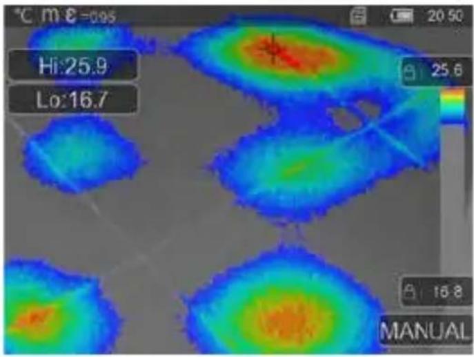
| Row | Column | Value | |---|---|---| | 7 | 1 | 9.22 | | 7 | 2 | 30.0 | | 7 | 3 | 9 | | 7 | 4 | 20.0 | | 7 | 5 | 11 | | 7 | 6 | 12 | | 8 | 1 | 10 | | 8 | 2 | 11 | | 8 | 3 | 12 | | 8 | 4 | 12 | | 8 | 5 | 12 | | 8 | 6 | 12 | | 13 | 1 | 14 | | 13 | 2 | 16 | | 13 | 3 | 18 | | 13 | 4 | 17 | | 13 | 5 | 19 | The image contains a color scale ranging from 9 to 12, but the numerical values are not explicitly labeled in the image. The text 'S:25.1', 'H:29.3', 'C:18.6' are visible at the top left. The 'AUTO' label is positioned near the bottom center of the chart.
https://packd.li/ll/ca2/ap/wi
14.1 CustomApps: Fabrieksinstelling
natural_image
Thermal imaging view showing heat signatures with no visible text or symbols16 Storingsdiagnose
https://packd.li/ll/ata/in
8 Marquage: + = Point central - = Point chaud - = Point froid
natural_image
Thermal imaging view showing heat signatures with no visible text or symbolshttps://packd.li/ll/ata/in
heatmap
| Row | Column | Value | |---|---|---| | 7 | 1 | 9.22 | | 7 | 2 | 30.0 | | 7 | 3 | 9 | | 7 | 4 | 20.0 | | 7 | 5 | 11 | | 7 | 6 | 12 | | 8 | 1 | 10 | | 8 | 2 | 11 | | 8 | 3 | 12 | | 8 | 4 | 12 | | 8 | 5 | 12 | | 8 | 6 | 12 | | 13 | 1 | 14 | | 13 | 2 | 16 | | 13 | 3 | 18 | | 13 | 4 | 17 | | 13 | 5 | 19 | The image contains a color scale ranging from 9 to 12, but the numerical values are not explicitly labeled in the image. The text 'S:25.1', 'H:29.3', 'C:18.6' are visible at the top left. The 'AUTO' label is positioned near the bottom center of the chart.
natural_image
Thermal imaging view showing heat signatures with no visible text or symbolshttps://packd.li/ll/ata/in
natural_image
Thermal imaging view showing heat signatures with bright yellow-orange regions against a dark blue background (no text or symbols visible)https://packd.li/ll/ata/in
natural_image
Thermal imaging view showing two bright hotspots on a dark background, with no visible text or symbols.https://packd.li/ll/ata/in
https://packd.li/ll/qrplus/ap/wi
!
natural_image
Thermal imaging view showing heat signatures with no visible text or symbolshttps://packd.li/ll/ata/in
The Ground Truth image displays a single, solid horizontal line. According to Rule 2 (UNDERSCORE & LINE RULES), this is a stylistic or background line, not a placeholder underscore. Therefore, the OCR result must ignore it and output nothing or only meaningful text. The provided OCR content is "____", which consists of four underscores. This is an incorrect interpretation of the line as a placeholder, violating the rule that stylistic lines must be ignored. The OCR has hallucinated underscores where none should exist based on the GT's visual context. Hence, the OCR result is inconsistent with the Ground Truth.