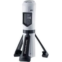
AC-tiveMaster PD - Measuring equipment Laserliner - Free user manual and instructions
Find the device manual for free AC-tiveMaster PD Laserliner in PDF.

| Product type | Voltage and continuity tester |
| Brand | Laserliner |
| Model | AC-tiveMaster PD |
| Category | Measuring equipment |
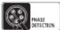
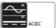
| Use | Automatic measurement of alternating (AC) and direct (DC) voltage, single-pole phase test, rotating magnetic field test |
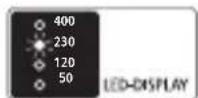
| Display | LED (light-emitting diodes) and audible signal |
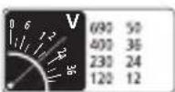
| Voltage range | 12, 24, 36, 50, 120, 230, 400, 690 V AC/DC |
| LED resolution | ± 12, 24, 36, 50, 120, 230, 400, 690 V AC/DC |
| Identification | Automatic voltage, polarity and range |
| Single-pole phase test | 100...690 V AC, 50/60 Hz |
| Continuity test | Resistance < 300 Ω, test current 5 μA |
| Rotating magnetic field | Left/right display (LED), 100...400 V AC, 50/60 Hz |
| Power supply | 2 AAA batteries (LR03, alkaline) 1.5 V |
| Current consumption | Max. 30 mA / approx. 250 mW |
| Operating temperature | -10 °C to 55 °C |
| Humidity | Max. 85% relative humidity |
| Overvoltage category | CAT III-1000V / CAT IV-600V |
| Pollution degree | 2 |
| Protection class | IP64 |
| Weight | 220 g |
| Standards | EN 61243-3; EN 61326 |
| Maintenance and cleaning | Clean with a dry, lint-free cloth. Calibrate annually. |
| Safety | Double insulation (class II). Caution for voltages > 25 V AC or 60 V DC. Do not touch the test probes. |
Frequently Asked Questions - AC-tiveMaster PD Laserliner
User questions about AC-tiveMaster PD Laserliner
0 question about this device. Answer the ones you know or ask your own.
Ask a new question about this device
Download the instructions for your Measuring equipment in PDF format for free! Find your manual AC-tiveMaster PD - Laserliner and take your electronic device back in hand. On this page are published all the documents necessary for the use of your device. AC-tiveMaster PD by Laserliner.
USER MANUAL AC-tiveMaster PD Laserliner


!
natural_image
Close-up of a wall-mounted electrical socket with a black tool inserted, showing wiring details (no text or symbols visible)Read the operating instructions and the enclosed brochure „Guarantee and additional notices“ completely. Follow the instructions they contain. Safely keep these documents for future reference.
Function/Application
Voltage and continuity tester for automatic measurement of AC (alternating current) and DC (direct current) voltages. The device can be used to perform a single-phase test and a rotating fi eld test while also indicating the phase direction. The information is indicated by means of an LED display and an acoustic signal.
Safety instructions
- The device must only be used in accordance with its intended purpose and within the scope of the specifications.
- Before every measurement make sure that the area to be checked (e.g. line) and the tester are in perfect operating condition. Test the device by connecting it to known voltage sources (e.g. a 230 V socket in the case of AC testing or a car battery in the case of DC testing). Stop using the device if one or a number of its functions fails.
- If you are working with voltages higher than 25 V AC/60 V DC, exercise extreme caution. Touching the electrical conductors at such voltages poses a risk of life-threatening electric shocks. Take particular care if the 50V warning LED is on.
- Do not use the device in environments in which there are conductive particles or where the occurrence of moisture (in the form of condensation, for example) can create transient conductivity.
- If the device comes into contact with moisture or other conductive residue, work must not be carried out under voltage. At and above voltages of 25 V AC/60 V DC, the presence of moisture creates the risk of life-threatening electric shocks. Clean and dry the device before use. When using the device outdoors, make sure that the weather conditions are appropriate and/or that suitable protection measures are taken.
-
If you are taking measurements in the hazardous vicinity of electrical installations, do not work alone and seek guidance from an electrically skilled person before starting work.
-
Isolate the device from all current sources before opening the battery compartment cover.
- The device must not be connected to voltages for longer than 30 seconds.
- Hold the device by the grip sections only. Do not touch the test prods during measurement.
- If possible, do not work alone.
Symbols
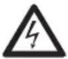
Hazardous electrical voltage warning: Unprotected live components inside the device housing may pose a risk of electric shock.

Danger area warning

Protection class II: The test device has reinforced or double insulation.
CAT III
Overvoltage category III: Equipment in fixed installations and for applications where specific requirements with regard to the reliability and availability of equipment have to be met, e.g. circuit-breakers in fixed installations and devices used in industrial applications which are permanently connected to the fixed installation.
CAT IV
Overvoltage category IV: Devices such as electricity meters, overcurrent circuit breakers and ripple-control units, which are intended for use at or near the infeed into the electrical installation of buildings, and specifically from the main distribution to the supply system.
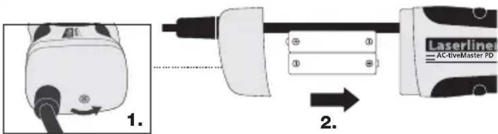
1 Insertion of batteries
!
The device is ready for use immediately once the batteries have been inserted. It does not have a separate ON/OFF switch and is therefore always active. As from a measuring voltage of 50 V, the device operates in emergency mode even without batteries.
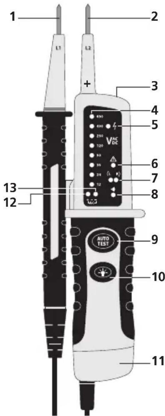
1 Test prod -
2 Test prod +
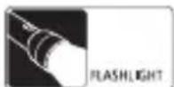
3 Flashlight
4 LEDs for indicating the voltage
5 LED for single-pole phase test
6 Voltage warning > 50V
7 LED for clockwise (L) / anticlockwise (R) rotating fi eld
8 LED for continuity
9 Self-test
10 Flashlight ON/OFF
11 Battery compartment
12 LED for +DC voltage
13 LED for -DC voltage
12 + 13
LED for AC voltage
2 Functional test/Self-test
- Test the voltage tester by applying it to familiar voltage sources
- Connect test prods (1) and (2). The LED for the continuity test (8) lights up and a signal sounds.
- Press the „AUTOTEST“ button. If the test is successful, all the LEDs (4) light up along with the LED for the continuity test (8) and a signal sounds.
3 Voltage test
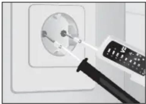
natural_image
Close-up of a wall-mounted electrical socket connected to a power cord (no text or symbols visible)Hold the base device (+) in your right hand and the second test prod (-) in your left hand. Now apply the test prods to the contacts to be tested (line, socket, etc.).
- The voltage tester is activated automatically at voltages of 12 V or above and indicates the measured voltage by lighting up the relevant LED (4).
Single-pole phase test
- Contact the conductor to be tested with test prod L2, L1 remains free during the measurement. The LED (5) will light up if an AC voltage is applied on the conductor.
- The single-pole phase test can only be performed with fully charged batteries inserted.
- The single-pole phase test can be carried out as from an AC voltage of approx. 100 V AC.
- When the single-pole phase test is carried out on the outer conductor, the indicator function may be adversely affected under certain conditions (e.g. when insulating personnel protective equipment is used or at insulated locations).

The single-pole phase test is not suitable for checking for zero voltage. To do this, you need to carry out a two-pole phase test.
5 Determining the direction of the rotating fi eld
Clockwise rotating fi eld
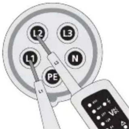
If the R LED (8) lights up, it means that what you think is phase L1 really is phase L1 and that what you think is phase L2 really is phase L2.
Anticlockwise rotating fi eld
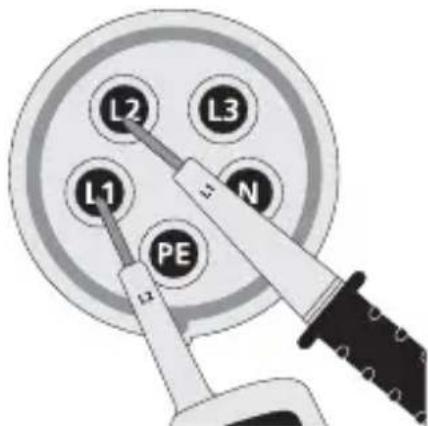
If the L LED (7) lights up, it means that what you think is phase L1 is actually phase L2 and that what you think is phase L2 is actually phase L1.
!
When you crosscheck this by switching round the test prods, the opposite symbol should light up instead.
6 Battery lamp
To switch on the battery lamp, press and hold down button 10. The light switches itself off automatically as soon as the button is released.
7 Calibration
The voltage tester needs to be calibrated and tested on a regular basis to ensure it produces accurate measurement results. We recommend carrying out calibration once a year.
EU directives and disposal
This device complies with all necessary standards for the free movement of goods within the EU.
This product is an electric device and must be collected separately for disposal according to the European Directive on waste electrical and electronic equipment.

Further safety and supplementary notices at:
www.laserliner.com/info
Technical data
| Voltage range | 12, 24, 36, 50, 120, 230, 400, 690 V AC/DC |
| LEDs ± 12, 24, 36, 50, 120, 230, 400, 690 V AC/DC | |
| Tolerance -30% to 0% of the reading | |
| Voltage detection Automatic | |
| Polarity detection Entire range | |
| Range detection Automatic | |
| Response time < 0.1 s, LED | |
| Frequency range 50/60 Hz | |
| Automatic load (RCD/FI) Yes | |
| Internal base load Approx. | 2.1 W at 600 V |
| Peak current 1s < 0.2 A / Is | (5 s) < 3.5 mA |
| ON time ON time = 30 s/10 min. | |
| Single-pole phase test | |
| Voltage range | 100 to 690 V AC |
| Frequency range 50/60 Hz | |
| Continuity test | |
| Resistance range | < 300 Ω |
| Testing current | 5 μA |
| Overvoltage protection | 690 V AC/DC |
| Indication of rotating fi eld direction | |
| Voltage range (LEDs) | 100 to 400 V |
| Frequency range 50/60 Hz | |
| Measuring principle | Two-pole with contact electrode |
| Power supply | 2x 1.5 Type AAA, LR03, alkaline |
| Power consumption | Max. 30 mA / approx. 250 mW |
| Operating temperature | -10°C ... 55°C |
| Humidity | Max. 85% relative air humidity |
| Overvoltage category | CAT III - 1000 V / CAT IV - 600 V |
| Pollution degree 2 | |
| Degree of protection | IP64 |
| Weight | 220 g |
| Test standards | EN 61243-3; EN 61326 |
Subject to technical alterations. 06.2010
!
natural_image
Close-up of a wall-mounted electrical socket with a power cord inserted, showing internal components (no text or symbols visible)natural_image
Close-up of a wall-mounted electrical socket with a black tool inserted, showing internal components (no text or symbols visible)natural_image
Close-up of a wall-mounted electrical socket with a black tool inserted, showing internal components (no text or symbols visible)natural_image
Close-up of a wall-mounted electrical socket with a power cord inserted, showing internal components (no text or symbols visible)natural_image
Close-up of a wall-mounted electrical socket with a black tool inserted, showing internal components (no text or symbols visible)natural_image
Close-up of a wall socket with a black tool inserted, showing a magnified view of the socket (no text or symbols visible)natural_image
Close-up of a wall-mounted device with a circular socket and a black tool inserted, no visible text or symbols.natural_image
Close-up of a wall-mounted electrical socket with a power cord and a black tool inserted, no visible text or symbols.natural_image
Close-up of a wall-mounted electrical socket with a power cord and a black tool inserted, no visible text or symbols.natural_image
Close-up of a wall-mounted electrical socket with a power cord and a black tool inserted, no visible text or symbols.natural_image
Close-up of a wall-mounted electrical socket with a power cord and a black tool inserted, no visible text or symbols.natural_image
Close-up of a wall-mounted electrical socket with a power cord and indicator lights (no visible text or symbols)natural_image
Close-up of a wall-mounted electrical socket with a power cord inserted, showing internal components (no text or symbols visible)natural_image
Close-up of a wall-mounted power socket connected to a digital display unit (no visible text or symbols)natural_image
Close-up of a wall-mounted electrical socket with a black tool inserted, showing wiring and components (no text or symbols visible)natural_image
Close-up of a wall-mounted electrical socket with a power cord and indicator light (no visible text or symbols)natural_image
Close-up of a wall-mounted electrical socket with a power cord inserted, showing internal components (no text or symbols visible)natural_image
Close-up of a wall-mounted electrical socket with a power cord and a black tool inserted, no visible text or symbols.natural_image
Close-up of a wall socket with a power cord inserted, showing internal components (no text or symbols visible)natural_image
Close-up of a wall socket with a power cord inserted, showing internal components (no text or symbols visible)SERVICE


Umarex GmbH & Co KG
- Laserliner -
Laserliner® Innovation in Tools