CableTracer Pro - Measuring equipment Laserliner - Free user manual and instructions
Find the device manual for free CableTracer Pro Laserliner in PDF.
| Product type | Universal and flexible line detector kit with transmitter and receiver |
| Brand | Laserliner |
| Model | CableTracer Pro |
| Category | Measuring equipment |
| Transmitter dimensions (L x H x D) | 68 x 130 x 32 mm |
| Receiver dimensions (L x H x D) | 59 x 192 x 37 mm |
| Transmitter weight (battery included) | approx. 200 g |
| Receiver weight (battery included) | approx. 240 g |
| Transmitter power supply | 1 x 9 V battery type IEC 6LR61 alkaline |
| Receiver power supply | 1 x 9 V battery type IEC 6LR61 alkaline |
| Nominal voltage | 12 – 250 V |
| Voltage measurement range | 12 – 400 V AC / DC |
| Transmission frequency | 125 kHz |
| Overvoltage category | CAT III 300 V |
| Measurement depth (voltage detection) | 0 – 0.4 m |
| Measurement depth (unipolar) | 0 – 2 m |
| Measurement depth (bipolar) | 0 – 0.5 m |
| Main functions | Cable tracing, fuse localization, short-circuit detection, cable break detection, water and heating pipe detection, conductor identification, non-contact mains voltage detection |
| Maintenance and cleaning | Protect from moisture and liquids; clean and dry before use; store in a dry place |
| Safety | Use only for intended purpose; do not use in CAT IV; observe safety instructions for voltages > 25 V AC or 60 V DC |
| Spare parts and repairability | Batteries replaceable by user; other spare parts not specified |
| General information | Compliant with EU standards; must be recycled according to WEEE directive; manual available in multiple languages |
Frequently Asked Questions - CableTracer Pro Laserliner
User questions about CableTracer Pro Laserliner
0 question about this device. Answer the ones you know or ask your own.
Ask a new question about this device
Download the instructions for your Measuring equipment in PDF format for free! Find your manual CableTracer Pro - Laserliner and take your electronic device back in hand. On this page are published all the documents necessary for the use of your device. CableTracer Pro by Laserliner.
USER MANUAL CableTracer Pro Laserliner
text_image
257 CODE SENSE LEVEL NCY NODE Laserliner® CableTracer RECV
text_image
VCH 200 120 100 12 LEVEL To LEVEL Laserliner® CableTracer TX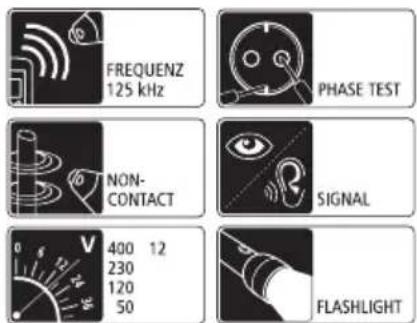
text_image
FREQUENZ 125 kHz PHASE TEST NON- CONTACT SIGNAL 400 12 230 120 50 FLASHLIGHT
text_image
Laserliner® Innovation in Toolstext_image
F G H I NCV SIG 1888 CODE 8 T SENSE LEVEL J K L M N Q P Otext_image
6LR61 9V Alkaliflowchart
graph LR
    A["HOLD"] --> B["LEVEL"]
    B --> C["simultaneous"]
    C --> D["CODE 1"]
    D --> E["4 LEVEL"]
    D --> F["5"]
    F --> G["CODE 2"]
    G --> H["LEVEL"]
    G --> I["0"]
    I --> J["CODE 3"]
    J --> K["LEVEL"]
    J --> L["0"]
    L --> M["0"]
text_image
NCV Q NCV MODEnatural_image
Close-up of a hand holding a circular object with a pen, next to another hand holding a tool (no visible text or symbols)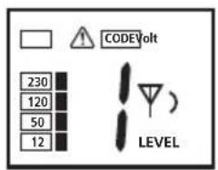
text_image
COVIDVolt 230 120 50 12 LEVEL

natural_image
Close-up of a hand holding a mechanical component, possibly a valve or tool, with no visible text or symbols.
text_image
CODE LEVEL)

natural_image
Close-up of a hand holding a plug inserted into a socket (no text or symbols visible)
natural_image
Close-up of a hand inserting a plug into a socket on an electrical outlet (no text or symbols visible)
natural_image
Interior view of a modern bathroom with sink, mirror, and bed (no text or symbols visible)natural_image
Interior view of a room with electrical fixtures and lighting fixtures (no text or symbols visible)natural_image
Interior view of a room with lighting fixtures and equipment, no visible text or symbolsnatural_image
Interior courtyard scene with fountain, water feature, and speaker equipment (no visible text or symbols)natural_image
Interior view of a room with electrical wiring and wall-mounted components, no visible text or symbolsnatural_image
Interior view of a room with electrical equipment and wiring, showing close-ups of components (no text or symbols visible)natural_image
Interior hallway scene with fire extinguishers and a speaker icon (no text or symbols)natural_image
Interior view of a room with wall-mounted electrical outlets, lighting fixtures, and electrical connections (no text or symbols visible)Read the operating instructions and the enclosed brochure „Guarantee and additional notices“ completely. Follow the instructions they contain. Safely keep these documents for future reference.
Function / Application
Universal, fl exible cable tracer set including sender and receiver.
- Non-contact tracing of the transmission signal by the receiver.
- Locates electrical cables, fuses, circuit breakers, metal pipes (such as heating pipes) and much more.
- Locates interrupted cables in existing installations and short-circuits in existing installation cables.
- May be used with or without mains voltage, up to max. 400V.
- Display of DC and AC voltages up to max. 400V.
– Single-pole search, for optimal cable and object search in greater depths.
- Two-pole search, for locating fuses, short-circuits and ground fault circuit interrupters.
– High transmission frequency of 125 KHz allows for exact and fail-safe locating performance without power failures.
– Signal coding allows as many as 7 senders to be used with one receiver and is thus ideal for complex installation settings.
- Integrated AC voltage detector recognises and locates live lines.
- Permanent AC voltage warnings increase safety with sender and receiver.
- Automatic and manual modes for adjustment to the particular measuring conditions.
- Integrated illumination of measuring points, powerful LED lighting.
- Overvoltage category CAT III (according to EN 61010-1, max. 300V) and all lower categories. The devices and accessories must not be used in overvoltage category CAT IV (e.g. low voltage installation sources).
How it works
Measurement is performed using one or more senders and one receiver. The sender feeds coded signals into the cable to be checked. The signal is a modulated current creating an electromagnetic field around the conductor. The receiver recognises this field, decodes it and is then able to find and locate cables with this signal.
Safety instructions
- The device must only be used in accordance with its intended purpose and within the scope of the specifications.
- Only the original measuring leads may be used. Their voltage, category and ampere rated powers must match those of the measuring device.
- Isolate the device from all current sources before opening the battery compartment cover. If possible, do not work alone.
- Hold the device by the grip sections only. Do not touch the test prods during measurement.
- If you are working with voltages higher than 25 V AC/60 V DC, exercise extreme caution. Touching the electrical conductors at such voltages poses a risk of life-threatening electric shocks.
- If the device comes into contact with moisture or other conductive residue, work must not be carried out under voltage. At and above voltages of 25 V AC/60 V DC, the presence of moisture creates the risk of life-threatening electric shocks. Clean and dry the device before use. When using the device outdoors, make sure that the weather conditions are appropriate and/or that suitable protection measures are taken.
- Take particular care if the Sender TX device displays the 50V warning.
- Do not use the device in environments in which there are conductive particles or where the occurrence of moisture (in the form of condensation, for example) can create transient conductivity.
- If you are taking measurements in the hazardous vicinity of electrical installations, do not work alone and seek guidance from an electrically skilled person before starting work.
- Before taking any measurements, make sure that both the area to be tested (e.g. a line), the test device and the accessories used (e.g. connection cable) are in proper working order. Test the device by connecting it to known voltage sources (e.g. a 230 V socket in the case of AC testing or a car battery in the case of DC testing). Stop using the device if one or a number of its functions fails.
- Do not leave the sender running permanently. Only use during actual measurement. After a measurement is taken, the sender must be removed from the measuring circuit.
- Do not use the device in environments containing explosive gases or vapour.
- Protect the device against contamination and damage, and make sure it is stored in a dry location.
- Do not expose the device to moisture or liquids. When using the device outdoors, make sure that the weather conditions are appropriate and/or that suitable protection measures are taken.
- The structure of the device must not be modified in any way.
– The measuring tools and accessories are not toys. Keep out of reach of children. - Please ensure compliance with the safety regulations set out by local and national authorities with regard to the correct and proper use of the device.
Symbols
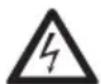
Hazardous electrical voltage warning: Unprotected live components inside the device housing may pose a risk of electric shock.

Danger area warning

Protection class II: The test device has reinforced or double insulation.
CAT III
Overvoltage category III: Equipment in fixed installations and for applications where specific requirements with regard to the reliability and availability of equipment have to be met, e.g. circuit-breakers in fixed installations and devices used in industrial applications which are permanently connected to the fixed installation.

Earth potential

Important notes. Must be observed.
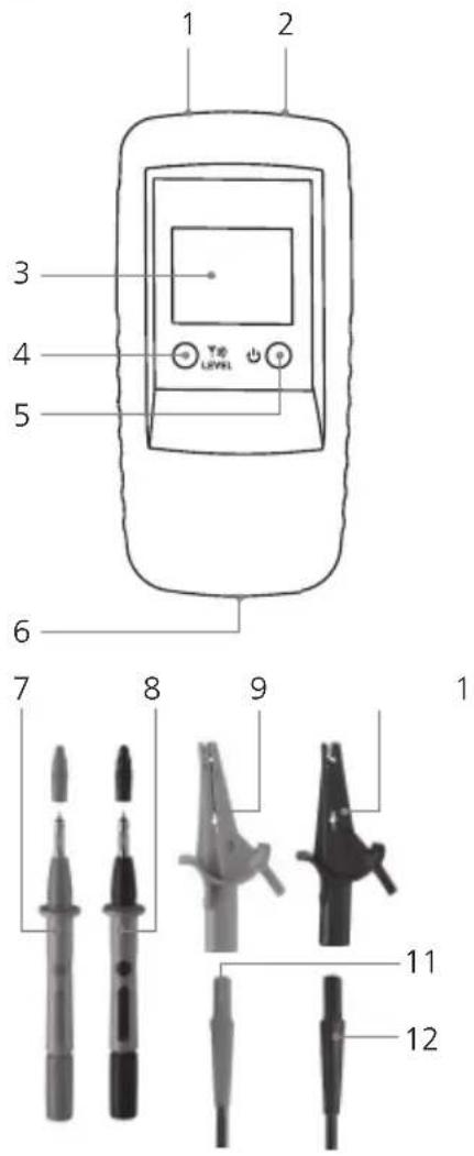
1 Description
text_image
1 2 3 4 5 6 7 8 9 1 11 12Sender TX
1 Connecting socket, red +
2 Connecting socket, black -
3 LC display
4 Sender code button:
Settings output power trans-
mission signal / illumination
LC display (hold button
down for 2 seconds) / set
sender code
5 ON/OFF buttonOFF: hold button down for 2 seconds
6 Battery compartment (rear)
7 Test prod, red +
8 Test prod, black -
9 Optional: Test clamp, red +
10 Optional: Test clamp, black -
11 Connecting cable, red +
12 Connecting cable, black -
text_image
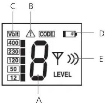
C B Volt CODE 400 230 120 50 12 LEVEL A D ELC display sender TX
A Sender code (1,2,3,4,5,6,7)
B External voltage warning
C Display external voltage (12, 50, 120, 230, 400V)
D Low battery charge
E Display output power transmission signal (level I, II, III)
text_image
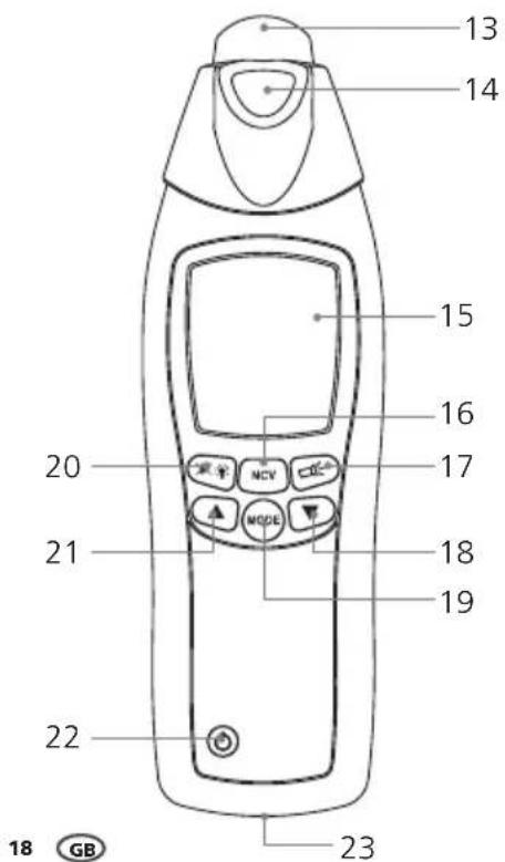
13 14 15 16 17 20 21 MODE 18 19 22 23 18 GBReceiver RECV
13 Sensor head
14 Flashlight
15 LC display
16 Toggle measurement mode: Locate cables (SIG) / Locate mains voltage (NCV)
17 ON/OFF button fl ash light
18 Reduce sensitivity
19 Toggle manual / automatic search mode
20 Illumination LC display /Turn on/off acoustic signal (hold button down for 2 seconds)
21 Increase sensitivity
22 ON/OFF button - OFF: hold button down for 2 seconds
23 Battery compartment (rear)
text_image
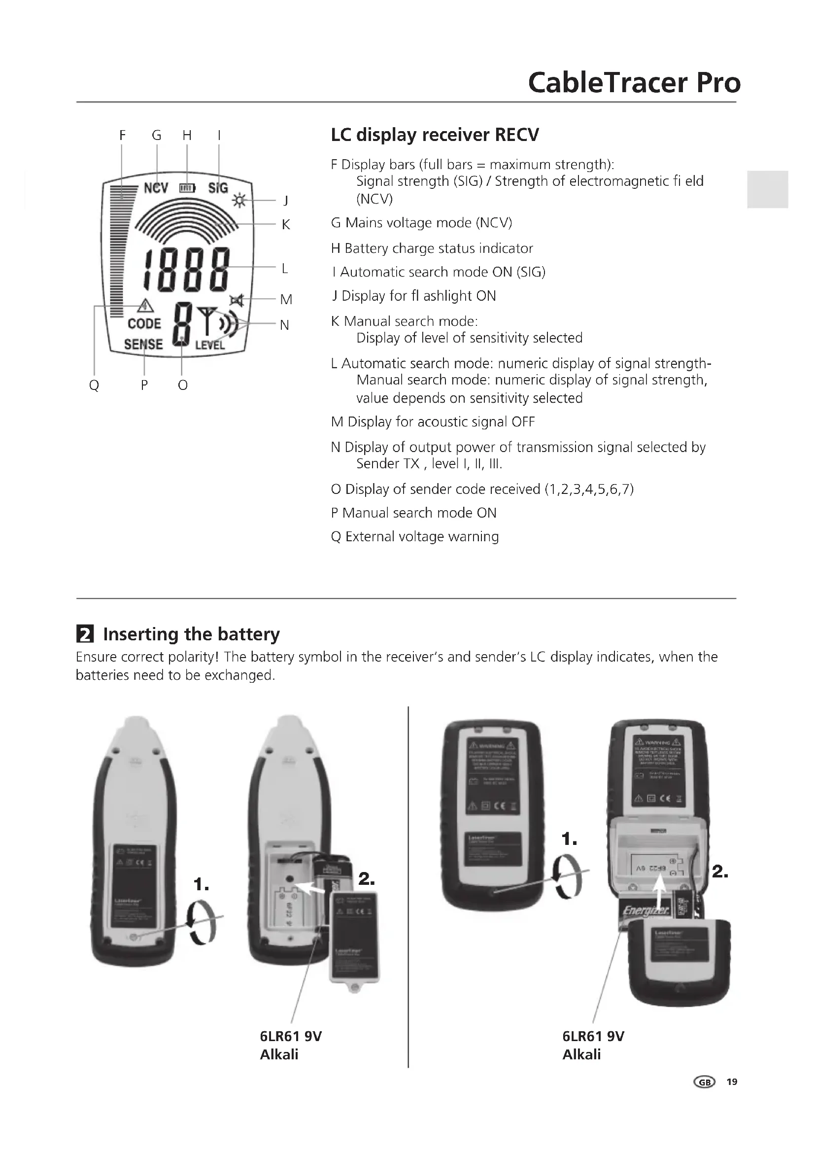
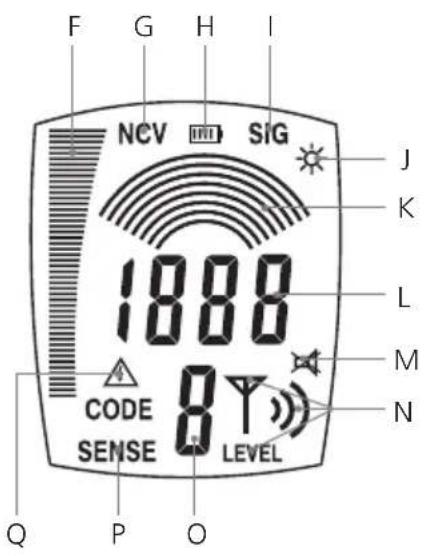
F G H I NCV SIG 1888 CODE 8 T SENSE LEVEL J K L M N Q P OLC display receiver RECV
F Display bars (full bars = maximum strength): Signal strength (SIG) / Strength of electromagnetic field (NCV)
G Mains voltage mode (NCV)
H Battery charge status indicator
I Automatic search mode ON (SIG)
J Display for fl ashlight ON
K Manual search mode: Display of level of sensitivity selected
L Automatic search mode: numeric display of signal strength Manual search mode: numeric display of signal strength, value depends on sensitivity selected
M Display for acoustic signal OFF
N Display of output power of transmission signal selected by Sender TX, level I, II, III.
O Display of sender code received (1,2,3,4,5,6,7)
P Manual search mode ON
Q External voltage warning
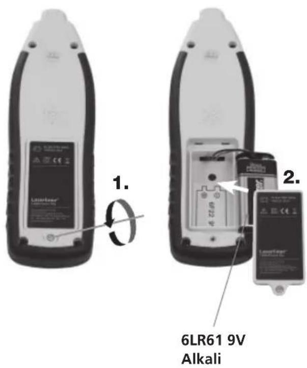
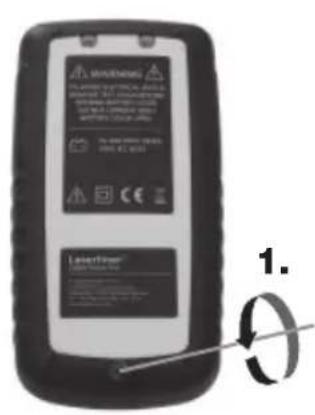
2 Inserting the battery
Ensure correct polarity! The battery symbol in the receiver's and sender's LC display indicates, when the batteries need to be exchanged.
text_image
1. 2. 6LR61 9V Alkali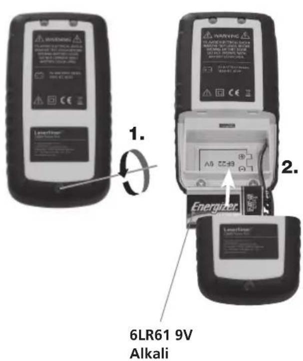
text_image
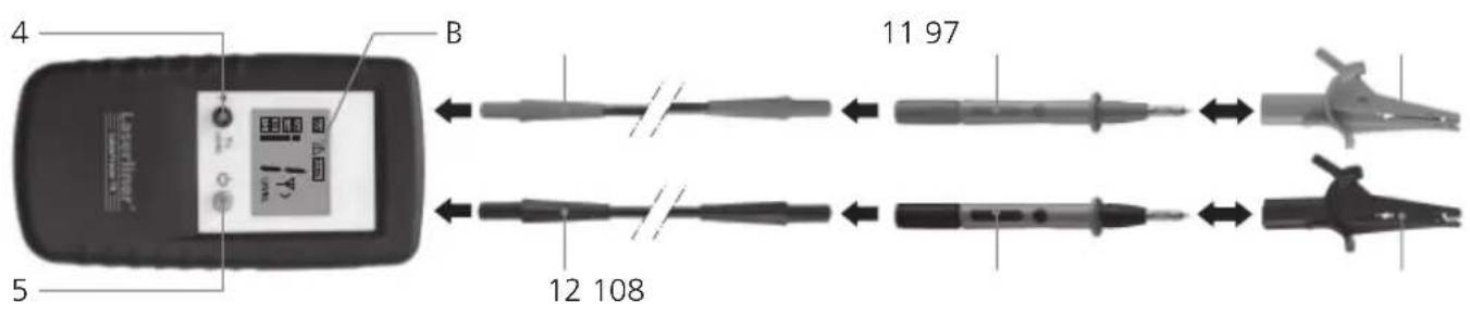
6LR61 9V Alkali3 Sender TX: Set-up
Connect the cables to the device. Ensure that the proper polarity is observed when doing so! Use the ON/OFF button (5) to switch the device on. Depending on the application, the output power of the signal can be selected using the sender code button (4): level 1 = lowest power; level 3 = highest power. Increasing the power from lowest to highest expands the operating distance of the receiver RECV by five times. If external voltage is present, the LC display indicates the magnitude of the voltage and the warning symbol (B). It also shows the sender code. To illuminate the display, press the sender code button (4) and hold it down for 2 seconds. To switch the device off, press the ON/OFF button and hold it down for 2 seconds. The device can be operated with or without voltage and is voltage-resistant up to 400 V.
text_image
4 B 11 97 5 12 108
- Be sure to observe the safety instructions when working with live cables.
- The integrated external voltage warning (B) of the sender must not replace checking for zero voltage!
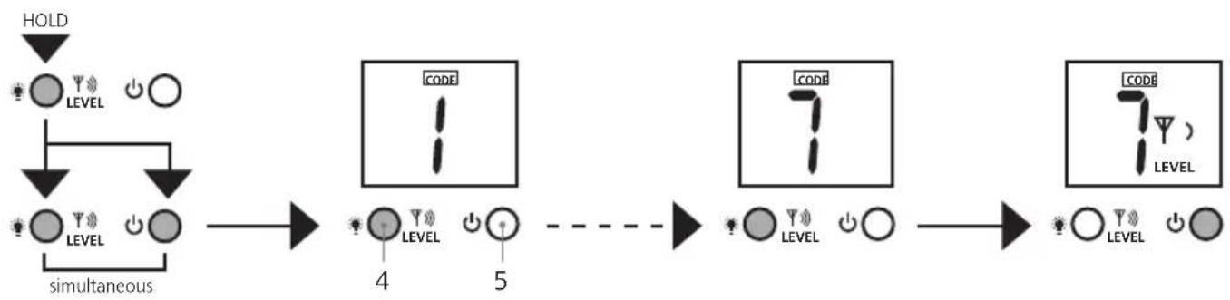
4 Sender TX: Set sender code
If you are using only one sender, it is not necessary to adjust the sender code. If you are using more than one sender, the sender code must be adjusted. To do this, ensure that the device is turned off. Then hold down the sender code button (4) and briefly press the ON/OFF button (5). Then press the sender code button and set the desired code. Set all devices in use to different sender codes. The ON/OFF button then saves the settings and switches the device on. There are 7 sender codes to choose from.
flowchart
graph LR
    A["HOLD"] --> B["LEVEL"]
    B --> C["simultaneous"]
    C --> D["CODE 1"]
    D --> E["4 LEVEL"]
    D --> F["5"]
    F --> G["CODE 2"]
    G --> H["LEVEL"]
    G --> I["0"]
    I --> J["CODE 3"]
    J --> K["LEVEL"]
    J --> L["0"]
    L --> M["0"]
5 Receiver RECV: Set receiving mode
!
The integrated external voltage warning (Q) of the receiver must not replace checking for zero voltage!
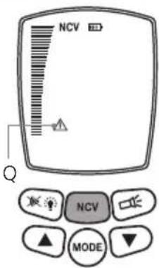
5A Mains voltage recognition
This mode works without a sender and is activated by pressing button 16. „NVC” appears on the LCD. This mode can be used to specifically locate live lines.
The strength of the electromagnetic field is displayed as bars. An additional acoustic receiver signal indicates in various pitches how far away the live cable is. The higher the pitch, the closer the live cable is. If external voltage is present, a warning symbol (Q) is displayed.
text_image
NCV Q NCV MODE5B Automatic search mode
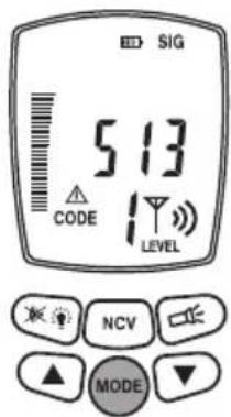
This mode only works with the sender. It is active as soon as the device is turned on and the LC display shows „SIG“. The device automatically sets the sensitivity in order to achieve optimal measuring results. Select this setting by pressing the Mode button.
The signal strength is indicated in bars and may be read numerically. An additional acoustic receiver signal indicates in various pitches how far away the desired cable is. The higher the pitch, the closer the desired cable is. The numerical display is the most exact way of locating the cable.
The sender code transmitted from the sender and the output power of the transmission signal are displayed as well. If external voltage is present, a warning symbol (Q) is displayed.
text_image
SIG 513 CODE LEVEL NCV MODE5C Manual search mode
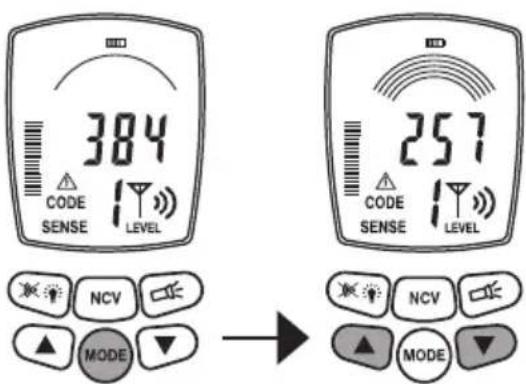
This mode only works with the sender and is selected by pressing the Mode button. „SENSE“ appears on the LC display. Use the arrow keys to adjust the sensitivity: 1 arch = maximum sensitivity; 8 arches = minimum sensitivity. Reducing the sensitivity can be useful, when the area to be measured needs to be limited to a certain range.
The signal strength is also determined by the output power of the sender. Therefore, also adjust the sender level in order to achieve the desired sensitivity.
text_image
384 CODE SENSE LEVEL 257 CODE SENSE LEVEL NCV MODE → NCV MODEThe signal strength is indicated in bars and provides a
detailed read numerically. An additional acoustic receiver signal indicates in various pitches how far away the desired cable is. The higher the pitch, the closer the desired cable is. The numerical display is the most exact way of locating the cable.
The sender code transmitted from the sender and the output power of the transmission signal are displayed as well. If external voltage is present, a warning symbol (Q) is displayed.
6 Prepare for measuring
Technically, the measurements can always be taken on cables with or without voltage. The receiving range of the receiver is generally wider when working with dead-voltage cables. The sender is always powered by battery.
- The measurements should always be taken on cables that have been shut down. - Be sure to follow the safety instructions when working under voltage.
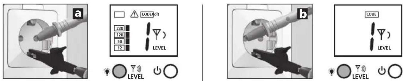
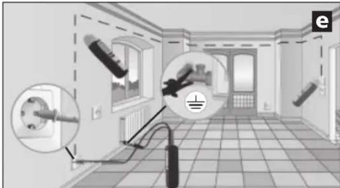
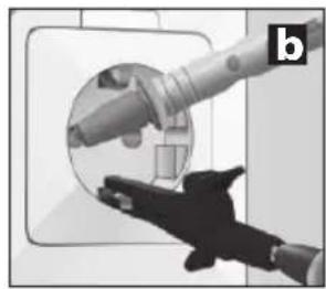
When working under voltage, the sender may determine the phase conductor. To do this, connect the black cable (-) to the protective earth and the red cable (+) to the conductor to be measured. You will know that it is the phase conductor if the display indicates voltage and a warning symbol (example a). If those are not displayed, it is either the neutral conductor N (example b) or the operating voltage is not present or the protective earth has not been connected properly.
If a fault current is already present in the measuring circuit, the ground fault circuit interrupter can be released by the additional power from the sender.
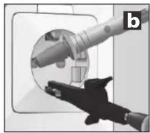
For safety reasons, the sender should only be connected from the phase against the neutral conductor (example c) when working under voltage. However, if the sender is connected from the phase against the protective earth (example d), it is essential to check whether the protective earth is properly earthed and fully functional. If this is not the case, any part connected to the earth may be under voltage.
natural_image
Close-up of a hand holding a plug inserted into a socket (no text or symbols visible)
natural_image
Hand inserting a plug into an electrical socket (no text or symbols visible)When checking the functionality of the protective earth, please ensure compliance with the safety regulations set out by local and national authorities.
7 Applications
There are three general applications:
A. Use with a receiver: Locate live lines.
B. Single-pole use with sender and receiver: Measurement of separate forward and return conductors, see images d and e in chapter 7B.
C. Two-pole use with sender and receiver: Measurements with common forward and return conductors in one cable, see image c.
7 Applications
7A Voltage detector
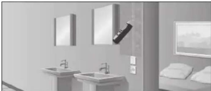
Turn on the receiver and switch to mains voltage mode. The device will now detect live electric conductors and can follow their course. The sender is not necessary for this process. See also chapter 5A.
natural_image
Interior view of a modern bathroom with sink, mirror, and bed (no text or symbols visible)7B Single-pole applications (separate forward and return conductors)
In this case, the sender is only connected to one conductor in a multi-core cable. This conductor then transmits the high-frequency signal of the sender. The return conductor in this case is the earth, ideally an earthing conductor or any other good earth connection. The detection depth is a maximum of 2m and is dependent on the surrounding material.
!
- The transmission signal of the sender should be earthed properly in order to achieve optimal results.
- When working under voltage, be sure to follow the safety instructions.
Examples for single-pole applications
7B-1 Trace cables / locate sockets
!
- Make the measuring circuit zero-potential.
- The lead transmission signal that is fed in may be transmitted to other cables if they are parallel to the lead over longer distances.
- To expand the range, it is recommended to separate the cable to be measured from the rest of the measuring circuit.
Connect the sender to the cable to be measured and to the protective earth. See image d in chapter 6. Then turn on the receiver and begin searching.
Recommended setting for the receiver: Manual search mode, maximum sensitivity, see chapter 5C.
Tip 1: As an alternative protective earth, you may use a fixed radiator. See image e. However, please ensure that the radiator is earthed correctly.
natural_image
Interior view of a room with electrical fixtures and wiring, no visible text or symbolsTip 2: A simple way to trace the course of the cable is to use the acoustic signal, the bar display and the numerical indication on the display. If you need to record the course of the cable in detail, simply mark those spots where the numerical display indicates the highest values.
Tip 3: You can increase your range by five times if you raise the output power of the sender from level 1 to 3.
Tip 4: In order to localise the desired cable further, it may be useful to earth parallel cables as well.
7B-2 Locate interrupted cables
!
- Make the measuring circuit zero-potential.
- An interrupted cable must have a transfer resistance of 100 kΩ or higher.
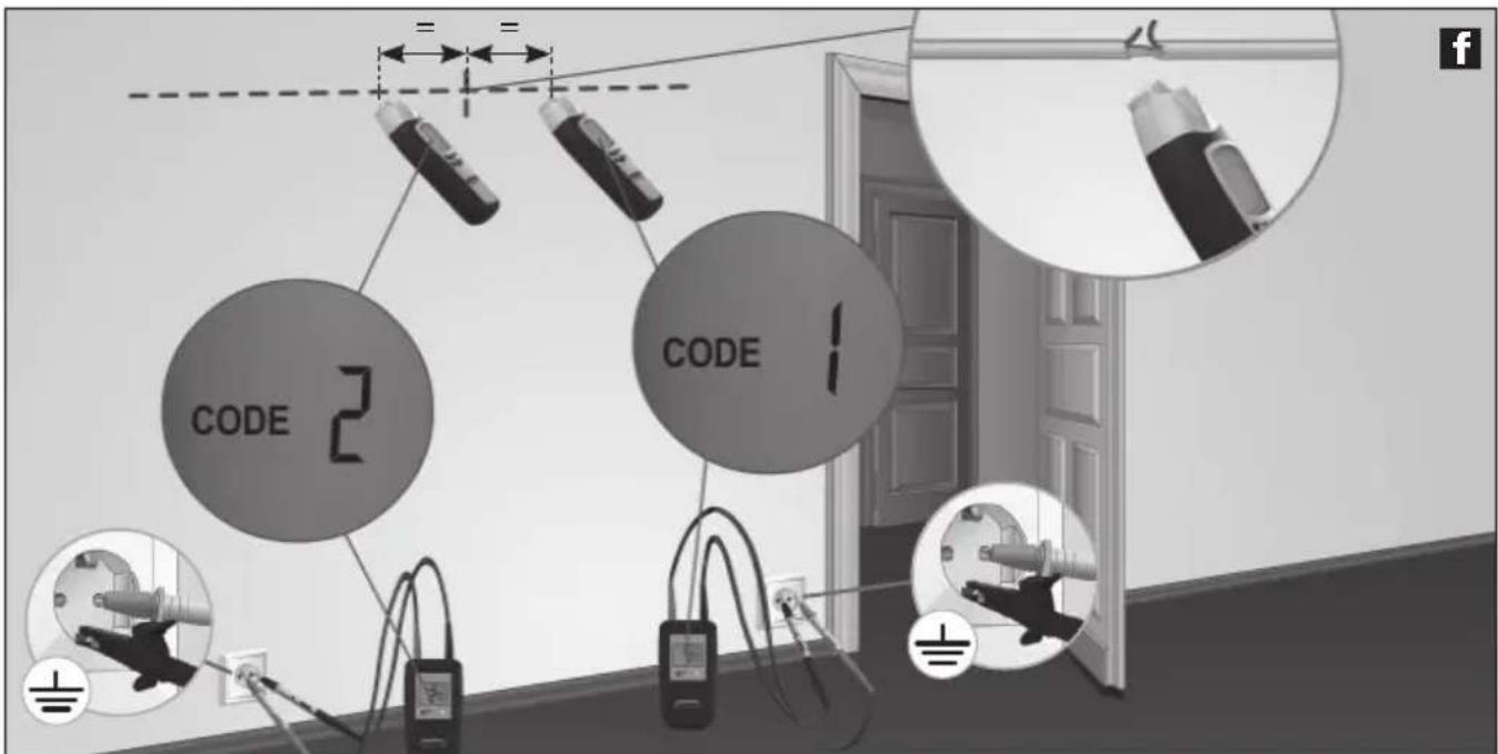
You may use two senders for this application. The second sender is not included in the set but is available as an accessory. Set the different sender codes in the sender devices and connect the cable to be measured and the protective earth. See image f in chapter 4. Then turn on the receiver and begin tracing the course of the cable. The interruption in the cable is located exactly in the middle between the two sender code values indicated in the LC display. Also follow tips 1 through 3.
Recommended setting for the receiver: Manual search mode, maximum sensitivity, see chapter 5C.
Tip 5: The cable interruption may be localised systematically by adjusting the sensitivity of the receiver and the output power of the sender.
Tip 6: To achieve optimal results, any cables not included in measuring should be earthed. This is particularly true for any unused individual conductors in multi-core cables and sheathed cables. If these are not earthed, the fed in signal may lead to crosstalk (due to capacitive and inductive coupling). The cable interruption can then no longer be adequately localised.
Tip 7: The search for interrupted cables in heated floors follows a similar concept. Ensure that there is no earthed shielding film above the heating wires. If necessary, separate it from the earthing connection.
text_image
CODE 2 CODE 1
natural_image
Interior view of a room with lighting fixtures and a close-up of a hand holding a device (no visible text or symbols)When working with one sender, the exact location of the interruption may not be as easy to find due to possible crosstalk of the electromagnetic field. See image g. In this case, the receiver displays the transmission signal after the interruption as a signifi cant decrease. The interruption is located where the signal begins decreasing.
7B-3 Find conductors underground

- Make the measuring circuit zero-potential.
Connect the sender to the desired cable and the protective earth and switch it on. Please ensure that the loop between the desired cable (red) and the earthing (black) is as big as possible. If the distance between them is to short, the receiver may not be able to locate the signal at maximum range. See also tips 2 and 3 as well as application 7B-6 on the next page.
Recommended setting for the receiver: Automatic search mode, see chapter 5B.
Tip 8: To increase the receiver's range, set the output power of the sender to the highest level. See chapter 3.
Tip 9: Pay attention to the bars indicated on the receiver during the search. They fluctuate greatly when panning the receiver over the desired cable. When the device is directly above the cable, the display shows the highest number of bars.
natural_image
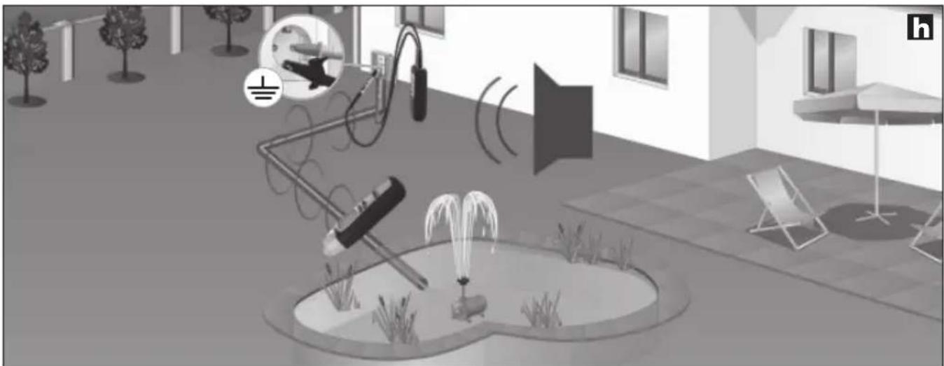
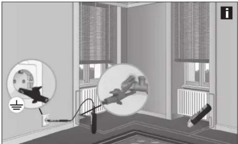
Interior courtyard scene with fountain, water spray, and wall-mounted equipment (no visible text or symbols)7B-4 Locate heating and water pipes

- Make the measuring circuit zero-potential.
- The heating pipes must be separated from the earth connection. Otherwise the receiver may not be able to locate the transmission signal at maximum range.
Connect the sender with the black cable (-) to the protective earth and with the red cable (+) to the radiator. See image i. The radiator must not be earthed while you do this. Then turn on the receiver and begin searching. Also follow tips 2 and 3.
Recommended setting for the receiver: Automatic search mode, see chapter 5B.
natural_image
Interior view of a room with electrical wiring and wall-mounted components, showing no visible text or symbols.7B-5 Locate nonconducting installation pipes
!
- For cable channels, remove the wires in the pipe from the power source and connect them to an earth potential.
- Make the measuring circuit zero-potential.
Guide a cable probe (copper wire) or a taut wire into the nonconducting installation pipe. Connect the sender with the red cable (+) to the probe and with the black cable (-) to an earth potential and switch on. Then turn on the receiver and begin searching. The receiver can now find the course of the installation pipes by means of the probe. Also follow tip 3.
Recommended setting for the receiver: Automatic search mode, see chapter 5B.
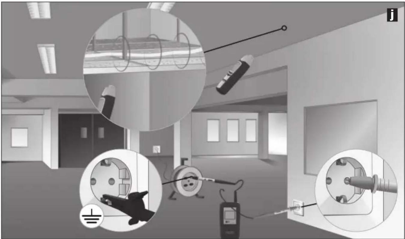
7B-6 Locate conductors in inaccessible places
!
- Make the measuring circuit zero-potential.
- When working under voltage, be sure to follow the safety instructions.
Make the loop between the measuring lead (red) and the return conductor (black) as big as possible. This improves reception and thus increases the range of the receiver. One way of achieving this is to use an extension cable. See image j. This is particularly helpful when working under voltage. The distance between measuring conductor and return conductor should be at least 2 m. Also follow tips 2, 3 and 6.
Recommended setting for the receiver: Automatic search mode, see chapter 5B.
Tip 10: The return conductor (black) may also be connected via the neutral conductor (N). The measuring conductor and return conductor should then be in the same electric circuit.
natural_image
Interior view of a room with electrical equipment and wiring, showing no visible text or symbols.7C Two-pole applications (common forward and return conductors)
These measurements may be taken in properly connected electric circuits (without cable interruptions). In this case, the sender is connected to two conductors in a common cable. The high-frequency signal of the sender goes back to the pick-up via the forward and return conductors. Measurements may be taken with or without voltage.
The detection depth is a maximum of 0.5 m and is dependent on the surrounding material.
Tip 11: When measuring under voltage, the individual phases (L1, L2, L3) may be distinguished, for example for sockets, lampholders, light switches etc.

- For safety reasons, the measuring circuit should be zero-potential.
- When working under voltage, be sure to follow the safety instructions.
- Additional earth wires and shieldung in the cable reduce the detection depth of the receiver.
- Shielding (such as metal coverings, metal supports etc.) in the vicinity reduces the range.
Examples for single-pole applications
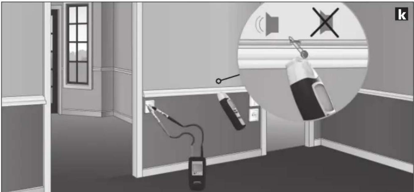
7C-1 Locate short-circuits

- Make the measuring circuit zero-potential.
- The short-circuit resistance must be less than 20 ohm. This can be determined using a multimeter. If the resistance is >20 ohm, you may be able to find the defect by searching for interrupted cables. See chapter 7B-2 on how to do this.
Connect the sender to short-circuited conductor and switch it on. Then turn on the receiver and begin searching. The receiver is able to trace the signal up to the location of the short-circuit. See image k. Adjust the receiver's sensitivity and the sender's output power little by little until you have located the short-circuit.
Recommended settings for the receiver: Manual search mode, minimum sensitivity, see chapter 5C.
natural_image
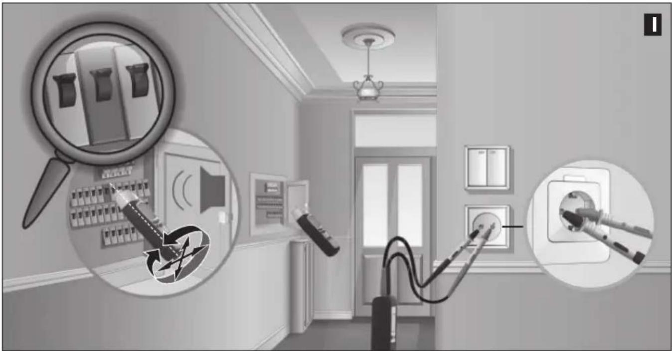
Interior hallway scene with fire extinguishers and a speaker, no visible text or symbols7C-2 Locate fuses
!
- Measurement under voltage! It is essential that you follow the safety instructions.
- The cover of the fuse box may only be removed by a skilled electrician.
Connect the sender to the phase conductor and the neutral conductor (N). Then turn on the receiver and begin searching. Follow the signal in the sub-distributor. See image I. Adjust the receiver's sensitivity and the sender's output power little by little until you have located the fuse.
The accuracy in locating fuses always depends on the various installation condition (RCD machines, types of fuses etc.).
Recommended settings for the receiver: Manual search mode, minimum sensitivity, see chapter 5C.
Tip 12: When locating a fuse, pay attention to the numbers in the numerical display. The highest value will appear when in the vicinity of the desired fuse.
Tip 13: Rotate the receiver around its longitudinal axis by 90^ or modify its horizontal and vertical positions. This will adjust the device to different automatic circuit breakers, which have magnetic coils installed in different positions.
Tipp 14: You will achieve the best results by measuring directly at the connections.
Tipp 15: These measurements may be taken without voltage as well. Some installation conditions produce more accurate results than others.
natural_image
Interior view of a room with electrical appliances and lighting fixtures (no text or symbols visible)8 Further functions of the device
- In poor lighting conditions, the display illumination may be switched on in both the sender and the receiver. See chapter 1.
- The receiver features a flashlight in addition. The flashlight switches itself off automatically after 1 minute. Do not switch the flashlight on or off while measuring mains voltage recognition (NCV) to maintain full functionality.
- The acoustic signal may be deactivated in the receiver. See chapter 1.
Technical data
| Sender CableTracer TX | |
| Output signal | 125 kHz |
| Nominal voltage | 12 – 250V |
| Measurement range | 12 – 400V AC/DC |
| Frequency range | 0 – 60 Hz |
| Overvoltage category | CAT III 300V, pollution degree 2 |
| Power supply | 1 x 9V block, IEC LR6, Alkali |
| Automatic switch-off | ca. 1 Std. |
| Operating temperature | 0°C – 40°C |
| Storage temperature | -20°C – 60°C |
| Operating height | 2000 m |
| Weight incl. battery | ca. 200 g |
| Dimensions (W x H x D) | 68 x 130 x 32 mm |
| Receiver CableTracer RECV | |
| Measurement ranges: | |
| Voltage detection | 0 – 0.4 m measuring depth |
| Single-pole measurement | 0 – 2 m measuring depth |
| Two-pole measurement | 0 – 0.5 m measuring depth |
| Power supply | 1 x 9V block, IEC LR6, Alkali |
| Automatic switch-off | ca. 10 minutes |
| Operating temperature | 0 °C – 40 °C |
| Storage temperature | -20 °C – 60 °C |
| Operating height | 2000 m |
| Weight incl. battery | ca. 240 g |
| Dimensions (W x H x D) | 59 x 192 x 37 mm |
Subject to technical alterations. 07.2010
EU directives and disposal
This device complies with all necessary standards for the free movement of goods within the EU.
This product is an electric device and must be collected separately for disposal according to the European Directive on waste electrical and electronic equipment.
Further safety and supplementary notices at: www.laserliner.com/info

A Zendcode (1,2,3,4,5,6,7)
text_image
F G H I NCV SIG 1888 CODE 8 T SENSE LEVEL Q P O J K L M NLC-display ontvanger RECV
F Staafdiagramweergave (volledige uitslag = maximale sterkte): signaalsterkte (SIG) ( elektromagnetische veldsterkte (NCV)
G Netspanningsmodus (NCV)
H Indicator batterij-laadtoestand
text_image
NCV Q NCV MODEnatural_image
Close-up of a hand holding a plug inserted into a socket (no text or symbols visible)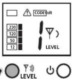
text_image
CODEVolt 230 120 50 12 LEVEL LEVEL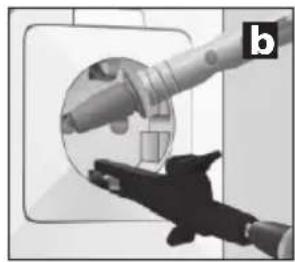
natural_image
Close-up of a hand holding a cylindrical device with a circular inset showing internal components (no visible text or symbols)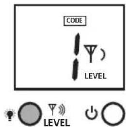
text_image
CODE LEVEL LEVEL
natural_image
Close-up of a hand holding a plug inserted into a socket (no text or symbols visible)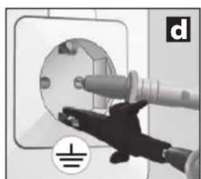
natural_image
Close-up of a hand inserting a plug into an electrical socket (no text or symbols visible)
natural_image
Interior view of a modern bathroom with sink, mirror, and bed (no text or symbols visible)natural_image
Interior view of a room with electrical fixtures and wiring, no visible text or symbolstext_image
CODE 2 CODE 1 = = f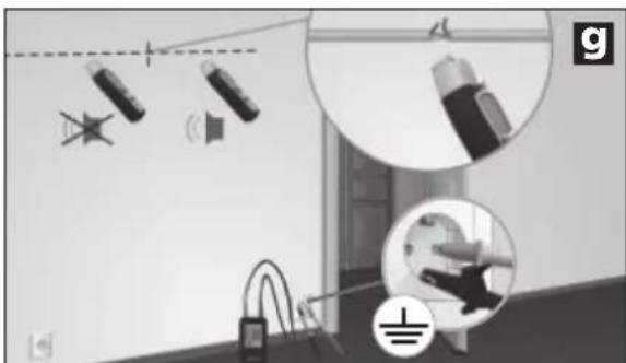
natural_image
Interior scene with lighting fixtures and a ceiling-mounted device, no visible text or symbolsnatural_image
Interior courtyard scene with fountain, water feature, and speaker equipment (no visible text or symbols)natural_image
Interior view of a room with electrical wiring and wall-mounted components, no visible text or symbolsnatural_image
Interior view of a room with electrical wiring and equipment, showing close-ups of components (no text or symbols visible)natural_image
Interior room scene with fire extinguishers and a wall-mounted device, no visible text or symbols7C-2 Zekeringen vinden
!
natural_image
Interior view of a room with wall-mounted electrical outlets and wall-mounted switches, showing lighting and wiring (no text or symbols)A Sendekode (1,2,3,4,5,6,7)
text_image
F G H I NCV SIG 1888 CODE 8 T SENSE LEVEL J K L M N Q P OLC-display modtager RECV
flowchart
graph LR
    A["HOLD"] --> B["LEVEL"]
    B --> C["simultaneous"]
    C --> D["CODE 1"]
    D --> E["4 LEVEL"]
    D --> F["5"]
    F --> G["CODE 2"]
    G --> H["LEVEL"]
    G --> I["0"]
    I --> J["CODE 3"]
    J --> K["LEVEL"]
    J --> L["0"]
    L --> M["0"]
text_image
NCV Q NCV MODEnatural_image
Close-up of a hand inserting a cable into a circular socket (no text or symbols visible)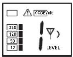
text_image
230 120 50 12 CODEVolt LEVEL
natural_image
Illustration of a robotic arm interacting with a circular mechanical component (no text or symbols visible)
text_image
CODE LEVEL)

natural_image
Close-up of a hand holding a plug inserted into a socket (no text or symbols visible)
natural_image
Close-up of a hand using a tool to clean or install a circular component, no visible text or symbols
natural_image
Interior view of a modern bathroom with sink, mirror, and bed (no text or symbols visible)natural_image
Interior view of a room with electrical fixtures and wiring, showing no visible text or symbolstext_image
CODE 2 CODE 1 = = f
natural_image
Interior view of a room with lighting fixtures and a close-up of a hand holding a device (no visible text or symbols)natural_image
Interior courtyard scene with fountain, water feature, and speaker (no visible text or symbols)natural_image
Interior view of a room with electrical wiring and wall-mounted components, no visible text or symbolsnatural_image
Interior view of a medical or laboratory facility with close-ups of electrical equipment and wiring (no visible text or symbols)natural_image
Interior hallway scene with fire extinguishers and a speaker, no visible text or symbolsnatural_image
Interior view of a room with electrical appliances and lighting fixtures (no text or symbols visible)text_image
F G H I NCV SIG 1888 CODE 8 T SENSE LEVEL J K L M N Q P Otext_image
NCV Q NCV MODEnatural_image
Close-up of a hand inserting a cable into a wall-mounted device (no text or symbols visible)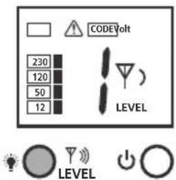
text_image
CODE Volt 230 120 50 12 LEVEL LEVEL
natural_image
Close-up of a hand holding a mechanical component, possibly a valve or tool, with no visible text or symbols.
text_image
CODE LEVEL LEVEL
natural_image
Close-up of a hand holding a plug inserted into a socket (no text or symbols visible)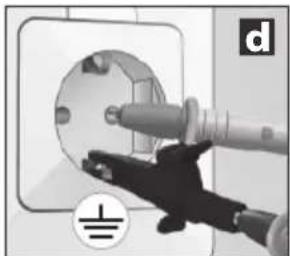
natural_image
Close-up of a hand inserting a plug into a socket on an electrical outlet (no text or symbols visible)
natural_image
Interior view of a modern bathroom with sink, mirror, and bed (no text or symbols visible)natural_image
Interior view of a room with electrical fixtures and wiring, no visible text or symbolstext_image
CODE 2 CODE 1 = = f
natural_image
Interior view of a room with ceiling lights, hanging cables, and a floor-mounted device (no visible text or symbols)natural_image
Interior courtyard scene with fountain, water spray, and wall-mounted equipment (no visible text or symbols)natural_image
Interior room scene with electrical wiring and wall-mounted components, no visible text or symbolsnatural_image
Interior view of a room with electrical equipment and circular insets showing wiring, sensors, and lighting (no visible text or symbols)natural_image
Interior hallway scene with fire extinguishers and a wall-mounted phone, featuring a circular inset showing sound waves (no text or symbols)text_image
F G H I NCV SIG 1888 CODE 8 T SENSE LEVEL J K L M N Q P OPantalla LC receptor RECV
flowchart
graph LR
    A["HOLD"] --> B["LEVEL"]
    B --> C["simultaneous"]
    C --> D["CODE 1"]
    D --> E["4 LEVEL"]
    D --> F["5"]
    F --> G["CODE 2"]
    G --> H["LEVEL"]
    G --> I["0"]
    I --> J["CODE 3"]
    J --> K["LEVEL"]
    J --> L["0"]
    L --> M["0"]
5 Receptor RECV: ajuste del modo de recepción
!
text_image
NCV Q NCV MODEnatural_image
Close-up of a hand holding a plug inserted into a socket (no text or symbols visible)
natural_image
Hand inserting a plug into an electrical socket (no text or symbols visible)
natural_image
Interior view of a modern bathroom with sink, mirror, and bed (no text or symbols visible)natural_image
Interior view of a room with electrical fixtures and wiring, showing no visible text or symbolstext_image
CODE 2 CODE 1 = = f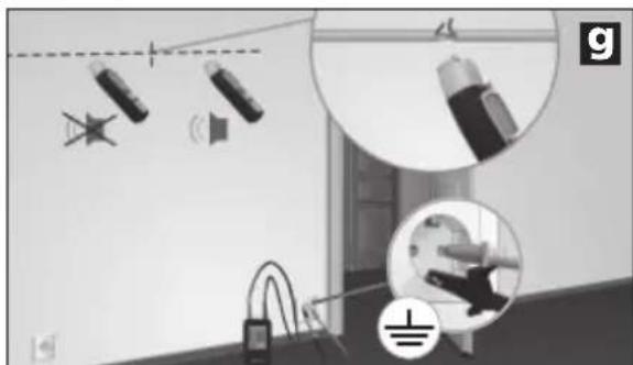
natural_image
Interior view of a room with lighting fixtures and electrical components (no visible text or symbols)natural_image
Interior courtyard scene with fountain, water spray, and wall-mounted equipment (no visible text or symbols)natural_image
Interior view of a room with electrical wiring and wall-mounted components, no visible text or symbolsnatural_image
Interior view of a room with electrical equipment and wiring, showing close-ups of components like wires, switches, and sensors (no text or symbols visible)natural_image
Interior hallway scene with fire extinguisher, phone, and sound barrier icons (no text or symbols)natural_image
Interior view of a room with wall-mounted electrical outlets and wall-mounted switches, showing lighting and wiring (no text or symbols)text_image
F G H I NCV SIG 1888 CODE 8 T SENSE LEVEL J K L M N Q P ODisplay LC ricevitore RECV
text_image
NCV Q NCV MODEnatural_image
Close-up of a hand inserting a plug into a circular socket (no text or symbols visible)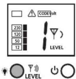
text_image
CODE Volt 230 120 50 12 LEVEL LEVEL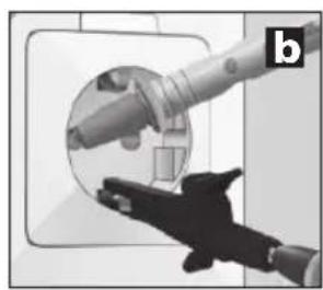
natural_image
Close-up of a robotic arm interacting with a circular mechanical component, no visible text or symbols
text_image
CODE LEVEL LEVEL
natural_image
Close-up of a hand holding a plug inserted into a socket (no text or symbols visible)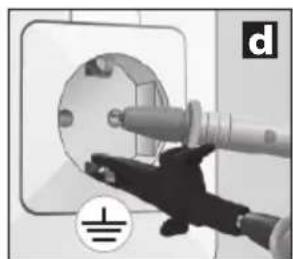
natural_image
Hand inserting a plug into an electrical socket (no text or symbols visible)
natural_image
Interior view of a modern bathroom with sink, mirror, and bed (no text or symbols visible)natural_image
Interior view of a room with electrical fixtures and wiring, showing no visible text or symbolstext_image
CODE 2 CODE 1 = = f
natural_image
Interior view of a room with lighting fixtures and equipment, no visible text or symbolsnatural_image
Interior courtyard scene with fountain, water feature, and speaker (no visible text or symbols)natural_image
Interior view of a room with electrical wiring and wall-mounted components, no visible text or symbolsnatural_image
Interior view of a room with electrical wiring and equipment, showing close-ups of components (no text or symbols visible)natural_image
Interior hallway scene with wall-mounted devices and a speaker icon (no text or symbols)natural_image
Interior view of a room with electrical appliances and lighting fixtures (no text or symbols visible)text_image
F G H I NCV SIG 1888 CODE 8 T SENSE LEVEL Q P O J K L M Nflowchart
graph LR
    A["HOLD"] --> B["LEVEL"]
    B --> C["simultaneous"]
    C --> D["CODE 1"]
    D --> E["4 LEVEL"]
    D --> F["5"]
    F --> G["CODE 2"]
    G --> H["LEVEL"]
    G --> I["0"]
    I --> J["CODE 3"]
    J --> K["LEVEL"]
    J --> L["0"]
    L --> M["LEVEL"]
text_image
NCV Q NCV MODEnatural_image
Close-up of a hand inserting a plug into a circular socket (no text or symbols visible)
text_image
CODEVolt 230 120 50 12 LEVEL LEVEL
natural_image
Close-up of a hand holding a mechanical component, possibly a valve or tool, with no visible text or symbols.
text_image
CODE LEVEL LEVEL
natural_image
Close-up of a hand holding a plug inserted into a socket (no text or symbols visible)
natural_image
Close-up of a hand inserting a plug into a socket on an electrical outlet (no text or symbols visible)
natural_image
Interior view of a modern bathroom with sink, mirror, and bed (no text or symbols visible)natural_image
Interior view of a room with electrical fixtures and lighting fixtures (no text or symbols visible)text_image
CODE 2 CODE 1 = = f
natural_image
Interior view of a room with ceiling lights, hanging cables, and a floor-mounted device (no visible text or symbols)natural_image
Interior courtyard scene with fountain, water feature, and speaker (no text or symbols)natural_image
Interior room scene with electrical wiring and wall-mounted components, no visible text or symbolsnatural_image
Interior view of a room with electrical wiring and equipment, showing close-ups of lighting fixtures (no text or symbols visible)natural_image
Interior hallway scene with fire extinguishers and a speaker icon (no text or symbols)natural_image
Interior view of a room with wall-mounted electrical outlets, lighting fixtures, and electrical connectors (no text or symbols visible)text_image
F G H I NCV SIG 1888 CODE 8 T SENSE LEVEL J K L M N Q P Onatural_image
Close-up of a handheld electronic device with battery and control panel, no visible text or symbols6LR61 9 V alkaliparisto
text_image
WARNING 1. 0
text_image
WARNING Energizer A5 CC-33 2.6LR61 9 V alkaliparisto
text_image
NCV Q NCV MODEnatural_image
Close-up of a hand holding a plug inserted into a socket (no text or symbols visible)
natural_image
Close-up of a hand using a power tool to clean or install an electrical socket (no text or symbols visible)
natural_image
Interior view of a modern bathroom with sink, mirror, and bed (no text or symbols visible)natural_image
Interior view of a room with electrical fixtures and wiring, showing no visible text or symbolsnatural_image
Interior scene with lighting fixtures and a ceiling-mounted device, no visible text or symbolsnatural_image
Interior courtyard scene with fountain, water feature, and speaker (no text or symbols)natural_image
Interior view of a room with electrical wiring and wall-mounted components, no visible text or symbolsnatural_image
Interior view of a room with electrical wiring and equipment, showing close-ups of lighting fixtures and wiring connections (no text or symbols visible)natural_image
Interior hallway scene with fire extinguishers and a speaker, no visible text or symbols7C-2 Sulakkeen haku
!
natural_image
Interior hallway with wall-mounted electrical outlets, switches, and lighting fixtures (no text or symbols visible)Mostrador LC Emissor TX
A Código emissor (1,2,3,4,5,6,7)
text_image
F G H I NCV SIG J 1888 CODE 87° LEVEL M N SENSE LEVEL Q P OMostrador LC Receptor RECV
text_image
NCV Q NCV MODEnatural_image
Close-up of a hand inserting a plug into a circular socket (no text or symbols visible)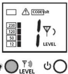
text_image
CODEVolt 230 120 50 12 LEVEL LEVEL
natural_image
Close-up of a hand holding a mechanical component, possibly a tool or device, with no visible text or symbols.
text_image
CODE LEVEL LEVEL
natural_image
Close-up of a hand holding a plug inserted into a socket (no text or symbols visible)
natural_image
Close-up of a hand inserting a plug into a socket on an electrical outlet (no text or symbols visible)
natural_image
Interior view of a modern bathroom with sink, mirror, and bed (no text or symbols visible)natural_image
Interior view of a room with electrical fixtures and wiring, showing no visible text or symbolstext_image
CODE 2 CODE 1 = = f
natural_image
Interior view of a room with lighting fixtures and electrical components (no visible text or symbols)natural_image
Interior courtyard scene with fountain, water feature, and speaker (no text or symbols)natural_image
Interior view of a room with electrical wiring and wall-mounted components, no visible text or symbolsnatural_image
Interior view of a room with electrical equipment and wiring, showing no visible text or symbols.natural_image
Interior room scene with fire extinguishers and a speaker icon, no visible text or symbolsnatural_image
Interior hallway with wall-mounted electrical outlets, switches, and a magnifying glass highlighting a device (no text or symbols)text_image
F G H I NCV SIG 1888 CODE 8 T SENSE LEVEL J K L M N Q P OLC-display mottagare RECV
flowchart
graph LR
    A["HOLD"] --> B["LEVEL"]
    B --> C["simultaneous"]
    C --> D["CODE 1"]
    D --> E["4 LEVEL"]
    D --> F["5"]
    F --> G["CODE 2"]
    G --> H["LEVEL"]
    G --> I["0"]
    I --> J["CODE 3"]
    J --> K["LEVEL"]
    J --> L["0"]
    L --> M["0"]
text_image
NCV Q NCV MODEnatural_image
Close-up of a hand inserting a plug into a circular socket (no text or symbols visible)
text_image
CODEVolt 230 120 50 12 LEVEL LEVEL
natural_image
Close-up of a hand holding a mechanical component, possibly a tool or device, with no visible text or symbols.
text_image
CODE LEVEL LEVEL
natural_image
Close-up of a hand holding a plug inserted into a socket (no text or symbols visible)
natural_image
Close-up of a hand inserting a plug into an electrical socket (no text or symbols visible)
natural_image
Interior view of a modern bathroom with sink, mirror, and bed (no text or symbols visible)natural_image
Interior view of a room with electrical fixtures and lighting fixtures (no text or symbols visible)text_image
CODE 2 CODE 1 = = f
natural_image
Interior view of a room with lighting fixtures and electrical connections (no visible text or symbols)natural_image
Interior courtyard scene with fountain, water feature, and speaker (no text or symbols)natural_image
Interior view of a room with electrical wiring and wall-mounted components, no visible text or symbolsnatural_image
Interior view of a room with electrical equipment and wiring, showing close-ups of lighting fixtures (no text or symbols visible)natural_image
Interior hallway with fire extinguisher and phone, showing safety symbols (no text or labels)natural_image
Interior hallway with wall-mounted electrical outlets and a power plug, showing lighting and wiring (no text or symbols)8 Ytterligare apparatfunktioner
A Sendekode (1,2,3,4,5,6,7)
B Advarsel mot ekstern spenning
C Indikering ekstern spenning (12, 50, 120, 230, 400V)
D Batteriets oppladingsnivå for lavt
text_image
F G H I NCV SIG 1888 CODE 8 T SENSE LEVEL J K L M N Q P OLC-display mottaker RECV
natural_image
Interior view of a handheld electronic device showing battery, switch, and display unit (no visible text or symbols)6LR61 9V alkali

text_image
WATERMUS 1. 0
text_image
WARNING Energizer A5 CC+3 2.6LR61 9V alkali
3 Sender TX Klargjøring
natural_image
Close-up of a hand inserting a plug into a circular socket (no text or symbols visible)
text_image
230 120 50 12 CODEVolt LEVEL

natural_image
Close-up of a hand holding a mechanical component, possibly a tool or device, with no visible text or symbols.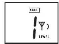
text_image
CODE LEVEL

natural_image
Close-up of a hand holding a plug inserted into a socket (no text or symbols visible)
natural_image
Close-up of a hand inserting a plug into a wall socket, with no visible text or symbols
natural_image
Interior view of a modern bathroom with sink, mirror, and bed (no text or symbols visible)natural_image
Interior view of a room with electrical fixtures and lighting fixtures (no text or symbols visible)text_image
CODE 2 CODE 1 = = f
text_image
Diagram illustrating lighting and electrical installation with labeled components and wiring connectionsnatural_image
Interior courtyard scene with fountain, water feature, and speaker (no text or symbols)natural_image
Interior view of a room with electrical wiring and wall-mounted components, no visible text or symbolsnatural_image
Interior view of a room with electrical equipment and wiring, showing no visible text or symbols.natural_image
Interior room scene with wall-mounted fire extinguishers and a speaker icon (no text or symbols)7C-2 Lokalisering av sikringer
!
natural_image
Interior view of a room with electrical outlets, switches, and lighting fixtures (no text or symbols visible)A Verici kodu (1,2,3,4,5,6,7)
text_image
F G H I NCV SIG 1888 CODE 8 T SENSE LEVEL J K L M N Q P OLCD Ekrani RECV Alici
text_image
NCV Q NCV MODE5B Otomatik arama modu
natural_image
Close-up of a hand inserting a plug into a circular socket (no text or symbols visible)
text_image
230 120 50 12 CODEVolt LEVEL

natural_image
Close-up of a hand holding a mechanical component, possibly a tool or device, with no visible text or symbols.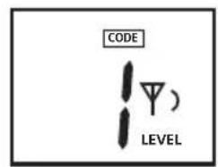
text_image
CODE LEVEL)

natural_image
Close-up of a hand holding a plug inserted into a socket (no text or symbols visible)
natural_image
Close-up of a hand inserting a plug into a socket on an electrical outlet (no text or symbols visible)
natural_image
Interior view of a modern bathroom with sink, mirror, and bed (no text or symbols visible)natural_image
Interior view of a room with electrical fixtures and wiring, showing no visible text or symbolstext_image
CODE 2 CODE 1 = = f
natural_image
Interior view of a room with ceiling lights, hanging cables, and ceiling fixtures (no visible text or symbols)natural_image
Interior courtyard scene with fountain, water feature, and wall-mounted speaker (no text or symbols)natural_image
Interior view of a room with electrical wiring and wall-mounted components, no visible text or symbolsnatural_image
Interior view of a room with electrical equipment and wiring, showing no visible text or symbols.natural_image
Interior hallway scene with fire extinguisher, phone, and sound barrier icons (no text or symbols)natural_image
Interior view of a room with electrical outlets, switches, and lighting fixtures (no text or symbols visible)text_image
F G H I NCV SIG J 1888 CODE 87° LEVEL M N SENSE LEVEL Q P Otext_image
NCV Q NCV MODEnatural_image
Close-up of a hand inserting a plug into a socket (no text or symbols visible)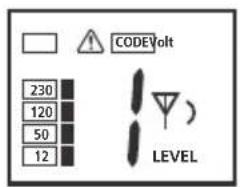
text_image
COVIDVolt 230 120 50 12 LEVEL
natural_image
Close-up of a robotic arm interacting with a circular mechanical component, no visible text or symbols
text_image
CODE LEVEL

natural_image
Close-up of a hand holding a plug inserted into a socket (no text or symbols visible)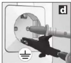
natural_image
Close-up of a hand inserting a plug into a socket on an electrical outlet (no text or symbols visible)
natural_image
Interior view of a modern bedroom with sink, mirror, and bed (no visible text or symbols)natural_image
Interior view of a room with electrical fixtures and lighting fixtures (no text or symbols visible)natural_image
Interior scene with lighting fixtures and a ceiling-mounted device, no visible text or symbolsnatural_image
Interior courtyard scene with fountain, water feature, and speaker (no visible text or symbols)natural_image
Interior view of a room with electrical wiring and wall-mounted components, no visible text or symbolsnatural_image
Interior view of a room with electrical wiring, sensors, and lighting fixtures (no visible text or symbols)natural_image
Interior hallway with fire extinguishers and a speaker icon, no visible text or symbolsnatural_image
Interior view of a room with wall-mounted electrical outlets and wall-mounted switches, showing lighting and wiring (no text or symbols)text_image
F G H I NCV SIG J 1888 CODE 87° LEVEL M N SENSE LEVEL Q P Otext_image
NCV Q NCV MODEnatural_image
Close-up of a hand inserting a plug into a circular socket (no text or symbols visible)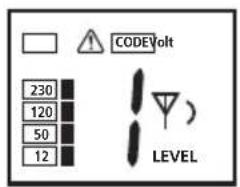
text_image
230 120 50 12 CODEVolt LEVEL

natural_image
Close-up of a hand holding a mechanical component, possibly a tool or device, with no visible text or symbols.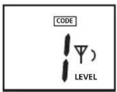
text_image
CODE LEVEL)

natural_image
Close-up of a hand holding a plug inserted into a socket (no text or symbols visible)
natural_image
Close-up of a hand using a power plug to clean electrical socket (no text or symbols visible)
natural_image
Interior view of a modern bathroom with sink, mirror, and bed (no text or symbols visible)natural_image
Interior view of a room with electrical fixtures and wiring, showing no visible text or symbolstext_image
CODE 2 CODE 1 = = f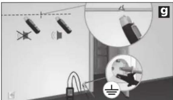
natural_image
Interior view of a room with lighting fixtures and equipment, no visible text or symbolsnatural_image
Interior courtyard scene with fountain, water feature, and wall-mounted speaker (no text or symbols)natural_image
Interior view of a room with electrical wiring and wall-mounted components, no visible text or symbolsnatural_image
Interior view of a room with electrical equipment and wiring, showing close-ups of sensors and components (no text or symbols visible)natural_image
Interior hallway scene with fire extinguishers and a speaker icon (no text or symbols)natural_image
Interior view of a room with electrical outlets, switches, and lighting fixtures (no text or symbols visible)text_image
F G H I NCV SIG 1888 CODE 8 T SENSE LEVEL J K L M N Q P Otext_image
NCV Q NCV MODEnatural_image
Close-up of a hand inserting a plug into a circular socket (no text or symbols visible)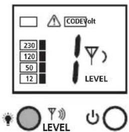
text_image
CODEVolt 230 120 50 12 LEVEL LEVEL
natural_image
Close-up of a hand holding a mechanical component, possibly a tool or device, with no visible text or symbols.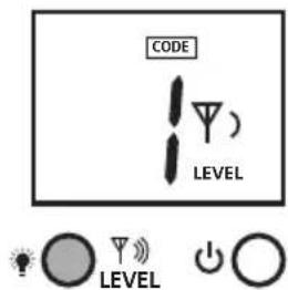
text_image
CODE LEVEL LEVEL
natural_image
Close-up of a hand holding a plug inserted into a socket (no text or symbols visible)
natural_image
Close-up of a hand inserting a plug into a socket on an electrical outlet (no text or symbols visible)
natural_image
Interior view of a modern bathroom with sink, mirror, and bed (no text or symbols visible)natural_image
Interior view of a room with electrical fixtures and lighting fixtures (no text or symbols visible)text_image
CODE 2 CODE 1 = = f
text_image
Diagram illustrating lighting and electrical installation with labeled components and magnified views of componentsnatural_image
Interior courtyard scene with fountain, water feature, and speaker (no visible text or symbols)natural_image
Interior view of a room with electrical wiring and wall-mounted components, no visible text or symbolsnatural_image
Interior view of a room with electrical equipment and wiring, showing close-ups of components (no text or symbols visible)natural_image
Interior hallway scene with fire extinguisher, hose, and spray bottle (no text or symbols)natural_image
Interior view of a room with electrical appliances and lighting fixtures (no text or symbols visible)text_image
F G H I NCV SIG 1888 CODE 8 T SENSE LEVEL J K L M N Q P Onatural_image
Close-up of a remote control device with battery and two connected devices, no visible text or symbols6LR61 9V leelis

text_image
WATERMUS 1. 0
text_image
WARNING Energizer A5 CC-33 2.6LR61 9V leelis
3 Saatja TX: etteseadistamine
text_image
NCV Q NCV MODEnatural_image
Close-up of a hand inserting a plug into a circular socket (no text or symbols visible)
text_image
230 120 50 12 CODEVolt LEVEL

natural_image
Illustration of a hand holding a cylindrical device with a handle, no visible text or symbols
text_image
CODE LEVEL

natural_image
Close-up of a hand holding a plug inserted into a socket (no text or symbols visible)
natural_image
Close-up of a hand using a power tool to clean or install an electrical socket (no text or symbols visible)
natural_image
Interior view of a modern bathroom with sink, mirror, and bed (no text or symbols visible)natural_image
Interior view of a room with electrical fixtures and lighting fixtures (no text or symbols visible)text_image
CODE 2 CODE 1 = = f
natural_image
Interior view of a room with lighting fixtures and a close-up of a device (no visible text or symbols)natural_image
Interior courtyard scene with fountain, water feature, and speaker (no visible text or symbols)natural_image
Interior view of a room with electrical wiring and wall-mounted components, no visible text or symbolsnatural_image
Interior view of a room with electrical equipment and wiring, showing close-ups of components (no text or symbols visible)natural_image
Interior hallway scene with fire extinguishers and a speaker icon (no text or symbols)7C-2 Kaitsmete leidmine
!
- Mõõtmine pinge all! Pidage ohutusjuhistest tingimata kinni.
natural_image
Interior hallway with electrical appliances and sound wave visualizations (no text or symbols)text_image
F G H I NCV SIG 1888 CODE 8 T SENSE LEVEL J K L M N Q P Onatural_image
Close-up of a handheld electronic device with battery and control panel, no visible text or symbols6LR61 9 V Alkali

text_image
WATERMUS 1. 0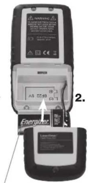
text_image
WARNING Energizer A5 CC-33 2.6LR61 9 V Alkali
text_image
NCV Q NCV MODEnatural_image
Close-up of a hand holding a plug inserted into a socket (no text or symbols visible)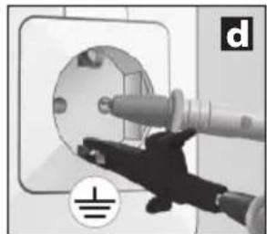
natural_image
Hand inserting a plug into an electrical socket (no text or symbols visible)
natural_image
Interior view of a modern bathroom with sink, mirror, and bed (no text or symbols visible)natural_image
Interior view of a room with electrical fixtures and wiring, showing no visible text or symbolstext_image
CODE 2 CODE 1 = = f
natural_image
Interior view of a room with lighting fixtures and a close-up of a device (no visible text or symbols)natural_image
Interior courtyard scene with fountain, water feature, and speaker (no text or symbols)natural_image
Interior view of a room with electrical wiring and wall-mounted components, no visible text or symbolsnatural_image
Interior view of a room with electrical wiring and equipment, showing close-ups of components (no text or symbols visible)natural_image
Interior hallway scene with fire extinguishers and a speaker icon (no text or symbols)natural_image
Interior view of a room with electrical appliances and lighting fixtures (no text or symbols visible)text_image
F G H I NCV SIG 1888 CODE 8 T SENSE LEVEL Q P O J K L M Ntext_image
NCV Q NCV MODEnatural_image
Close-up of a hand inserting a plug into a circular socket (no text or symbols visible)
text_image
230 120 50 12 CODEVolt LEVEL

natural_image
Close-up of a robotic arm holding a circular mechanical component, with no visible text or symbols
text_image
CODE LEVEL)

natural_image
Close-up of a hand holding a plug inserted into a socket (no text or symbols visible)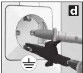
natural_image
Close-up of a hand inserting a plug into a socket on an electrical outlet (no text or symbols visible)
natural_image
Interior view of a modern bedroom with sink, mirror, and bed (no visible text or symbols)natural_image
Interior view of a room with electrical fixtures and lighting fixtures (no text or symbols visible)text_image
CODE 2 CODE 1 = = f
natural_image
Interior scene with lighting fixtures and a ceiling-mounted device, no visible text or symbolsnatural_image
Interior courtyard scene with fountain, water feature, and speaker (no visible text or symbols)natural_image
Interior view of a room with electrical wiring and wall-mounted components, no visible text or symbolsnatural_image
Interior view of a room with electrical equipment and wiring, showing no visible text or symbols.natural_image
Interior hallway scene with wall-mounted devices and a speaker icon (no text or symbols)natural_image
Interior view of a room with electrical appliances and lighting fixtures (no text or symbols visible)text_image
F G H I NCV SIG 1888 CODE 8 T SENSE LEVEL Q OP J K L M NAfi şaj LC receptor RECV
text_image
NCV Q NCV MODEnatural_image
Close-up of a hand inserting a plug into a circular socket (no text or symbols visible)
text_image
CODEVolt 230 120 50 12 LEVEL LEVEL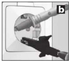
natural_image
Close-up of a hand holding a mechanical component, possibly a tool or device, with no visible text or symbols.
text_image
CODE LEVEL LEVEL
natural_image
Close-up of a hand holding a plug inserted into a socket (no text or symbols visible)
natural_image
Close-up of a hand using a power tool to clean or install an electrical socket (no text or symbols visible)
natural_image
Interior view of a modern bathroom with sink, mirror, and bed (no text or symbols visible)natural_image
Interior view of a room with electrical fixtures and lighting fixtures (no text or symbols visible)text_image
CODE 2 CODE 1 = = f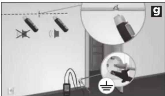
natural_image
Interior view of a room with lighting fixtures and equipment, no visible text or symbolsnatural_image
Interior courtyard scene with fountain, water feature, and camera setup (no visible text or symbols)natural_image
Interior view of a room with electrical wiring and wall-mounted components, no visible text or symbolsnatural_image
Interior view of a room with electrical equipment and wiring, showing no visible text or symbols.natural_image
Interior hallway scene with fire extinguisher, phone, and sound barrier icons (no text or symbols)natural_image
Interior view of a room with electrical appliances and lighting fixtures (no text or symbols visible)text_image
F G H I NCV SIG J K L M N CODE 8 T SENSE LEVEL Q P Otext_image
NCV Q NCV MODEnatural_image
Close-up of a hand inserting a plug into a circular socket (no text or symbols visible)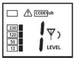
text_image
230 120 50 12 CODEVolt LEVEL

natural_image
Illustration of a hand holding a cylindrical device with a handle, no visible text or symbols
text_image
CODE LEVEL

natural_image
Close-up of a hand holding a plug inserted into a socket (no text or symbols visible)
natural_image
Close-up of a hand using a power tool to clean or install an electrical socket (no text or symbols visible)
natural_image
Interior view of a modern bathroom with sink, mirror, and bed (no text or symbols visible)natural_image
Interior view of a room with electrical fixtures and wiring, showing no visible text or symbolstext_image
CODE 2 CODE 1 = = f
natural_image
Interior view of a room with ceiling lights, hanging cables, and a floor-mounted device (no visible text or symbols)natural_image
Interior courtyard scene with fountain, water feature, and speaker equipment (no visible text or symbols)natural_image
Interior view of a room with electrical wiring and wall-mounted components, no visible text or symbolsnatural_image
Interior view of a room with electrical equipment and wiring, showing no visible text or symbols.natural_image
Interior hallway scene with wall-mounted devices and a speaker icon (no text or symbols)natural_image
Interior view of a room with electrical appliances and lighting fixtures (no text or symbols visible)text_image
F G H I NCV SIG 1888 CODE 8 T SENSE LEVEL J K L M N Q P Onatural_image
Close-up of a handheld electronic device with battery and control panel, no visible text or symbols6LR61 9V Alkali

text_image
WATERMUS 1. 0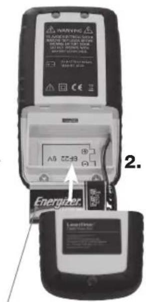
text_image
WARNING Energizer A5 CC-B3 2. EnergyTransfer6LR61 9V Alkali
text_image
NCV Q NCV MODEnatural_image
Close-up of a hand inserting a plug into a circular socket (no text or symbols visible)
text_image
COVIDVolt 230 120 50 12 LEVEL

natural_image
Close-up of a hand holding a mechanical component, possibly a tool or device, with no visible text or symbols.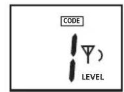
text_image
CODE LEVEL

natural_image
Close-up of a hand holding a plug inserted into a socket (no text or symbols visible)
natural_image
Close-up of a hand using a power tool to clean or install an electrical socket (no text or symbols visible)
natural_image
Interior view of a modern bathroom with sink, mirror, and bed (no text or symbols visible)natural_image
Interior view of a room with electrical fixtures and wiring, showing no visible text or symbolsnatural_image
Interior view of a room with ceiling lights, hanging cables, and a floor-mounted device (no visible text or symbols)natural_image
Interior courtyard scene with fountain, water feature, and speaker equipment (no visible text or symbols)natural_image
Interior view of a room with electrical wiring and wall-mounted components, no visible text or symbolsnatural_image
Interior view of a room with electrical wiring and equipment, showing close-ups of lighting fixtures (no text or symbols visible)natural_image
Interior hallway scene with wall-mounted devices and a speaker icon (no text or symbols)natural_image
Interior view of a room with electrical appliances and lighting fixtures (no text or symbols visible)natural_image
Interior hallway with wall-mounted electrical control panel and power plug, showing magnified views of components (no text or symbols)SERVICE


Umarex GmbH & Co KG
-Laserliner-