Cubus G 210 S - Laser level Laserliner - Free user manual and instructions
Find the device manual for free Cubus G 210 S Laserliner in PDF.
| Product type | Rotary laser level |
| Brand and model | Laserliner Cubus G 210 S |
| Dimensions (l x h x p) | 130 x 160 x 145 mm (with tripod and wall bracket) |
| Weight | 1300 g (with tripod and wall bracket) |
| Power supply | Rechargeable Li-ion battery 7.4V / 2.6Ah / 19.24Wh; charge via 9V adapter or USB-C; autonomy approx. 25 h (red/green); charging time approx. 4 h |
| Remote control power supply | 2 x 1.5V LR03 (AAA) batteries |
| Self-leveling range | ± 4° |
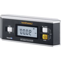
| Accuracy | ± 0.15 mm/m |
| Rotation speeds | 0, 30, 330, 600 rpm |
| Operating modes | Rotation, Scanner (10°/45°/90°/180°), Point (fixed laser) |
| Anti-drift system | ADS (Anti-Drift System): laser stops in case of external movement |
| Manual tilting function | Yes, activated via auto/slope button and using the angle plate |
| Reference laser | Yes, for alignment in vertical mode |
| Receiver compatibility | SensoLite 110, 210, 410, SensoMaster M350 (red); SensoLite G 110, G 210, 410, SensoMaster M350 (green) |
| Remote control | Infrared, range up to 30 m |
| Laser wavelength | Red: 635 nm; Green: 515 nm |
| Laser class | 2 (< 1 mW) according to EN 60825-1:2014/A11:2021 / EN 50689:2021 |
| Protection | IP66 (dust and rain) |
| Working conditions | -10 °C to 50 °C, max. humidity 80% RH, max. altitude 4000 m |
| Storage conditions | -10 °C to 70 °C, max. humidity 80% RH |
| Tripod thread | 5/8" lateral |
| Maintenance and cleaning | Clean with a slightly damp cloth; do not use solvents; remove battery before prolonged storage; annual calibration recommended |
| Safety | Do not look into the laser beam; avoid reflective surfaces; do not use at eye level (1.40-1.90 m); observe safety distances |
| After-sales service | Contact UMAREX-LASERLINER for calibration, repairs or spare parts |
| General information | Full manual available at notice-facile.com; recycling according to European and British directives |
Frequently Asked Questions - Cubus G 210 S Laserliner
User questions about Cubus G 210 S Laserliner
0 question about this device. Answer the ones you know or ask your own.
Ask a new question about this device
Download the instructions for your Laser level in PDF format for free! Find your manual Cubus G 210 S - Laserliner and take your electronic device back in hand. On this page are published all the documents necessary for the use of your device. Cubus G 210 S by Laserliner.
USER MANUAL Cubus G 210 S Laserliner
text_image
Laserliner auto slope tilt CUBUSSENSOR
AUTOMATIC
ADS
Tilt

lock

auto auto man
Laserliner
DE
02
EN
13
NL
24
DA
35
FR
46
ES
57
IT
68
PL
79
FI
90
PT
01
SV
12
NO
23
TR
34
RU
45
UK
56
CS
67
ET
78
RO
89
BG
00
EL
11
SL
22
HU
33
SK
44
HR
55
!
text_image
Warning sign with sunburst symbol inside triangle, indicating caution or hazardnatural_image
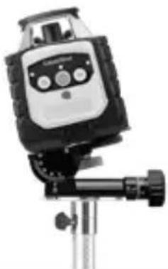
Exterior view of a LaserRiver device with control buttons and a USB-C logo (no readable text or symbols beyond branding)Laserliner

text_image
a b c Laserliner CUBUS d f e tiltnatural_image
Close-up of two batteries with one labeled 'AXALINE' and the other a CDK card, showing no visible text or symbols on the devices themselves.
text_image
Laserliner 8 9 10 11 12 13 1natural_image
Close-up of a precision optical instrument with adjustable screen and lever (no visible text or symbols)man
(


natural_image
Architectural cross-section diagram of a building facade with structural beams and framing (no text or symbols)Lasermodi
Rotations-Modus
natural_image
Illustration of a portable device with a circular arrow symbol on the left (no text or symbols present)Punkt-Modus
natural_image
Illustration of a robot with directional arrows indicating rotation (no text or symbols)Scan-Modus
natural_image
Illustration of a propeller with four blades and control buttons (no text or symbols)Handempfänger-Modus
natural_image
Illustration of a portable device and a smartphone with circular arrows indicating rotation (no text or symbols)Cubus Green: https://packd.li/ll/APV/in
Completely read through the operating instructions, the "Warranty and Additional Information" booklet as well as the latest information under the internet link at the end of these instructions. Follow the instructions they contain. This documents must be kept in a safe place and if the laser device is passed on, this documents must be passed on with it.
Intended use
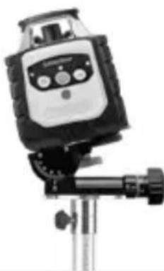
This rotary laser is designed for aligning the horizontal plane. Thanks to the 5/8" thread integrated on the side of the housing for mounting on a tripod, it is also suitable for vertical alignment. The rotary laser has a manual tilt function. The Cubus model is compatible with the SensoLite 110, SensoLite 210, SensoLite 410 and SensoMaster M350 receivers and the Cubus Green with the SensoLite G 110, SensoLite G 210, SensoLite 410 and SensoMaster M350 receivers.
General safety instructions
- The device must only be used in accordance with its intended purpose and within the scope of the specifications.
- The measuring tools and accessories are not toys. Keep out of reach of children.
- Modifications or changes to the device are not permitted, this will otherwise invalidate the approval and safety specifications.
- Do not expose the device to mechanical stress, extreme temperatures, moisture or significant vibration.
- The device must no longer be used if one or more of its functions fail, the battery charge is weak, or the housing has been damaged.
- When using the device outdoors, make sure that the weather conditions are appropriate and/or that suitable protection measures are taken.
- Please ensure compliance with the safety regulations set out by local and national authorities with regard to the correct and proper use of the device.
Safety instructions
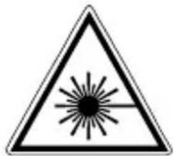
Using class 2 lasers
natural_image
Warning symbol with a triangular triangle containing a central starburst (no text or numbers)Laser radiation! Do not stare into the beam! Class 2 laser| < 1 mW · 635 / 515 nm
EN 60825-1:2014/A11:2021 / EN 50689:2021
- Attention: Do not look into the direct or reflected beam.
- Do not point the laser beam towards persons.
- If a person's eyes are exposed to class 2 laser radiation, they should shut their eyes and immediately move away from the beam.
- Under no circumstances should optical instruments (magnifying glass, microscope, binoculars) be used to look at the laser beam or reflections.
- Do not use the laser at eye level (1.40 ... 1.90 m)
- Reflective, specular or shiny surfaces must be covered whilst laser devices are in operation.
- In public areas shield off the laser beam with barriers and partitions wherever possible and identify the laser area with warning signs.
Safety instructions
Dealing with electromagnetic radiation
- The measuring device complies with electromagnetic compatibility regulations and limit values in accordance with EMC-Directive 2014/30/EU.
- Local operating restrictions – for example, in hospitals, aircraft, petrol stations or in the vicinity of people with pacemakers – may apply. Electronic devices can potentially cause hazards or interference or be subject to hazards or interference.
- The measuring accuracy may be affected when working close to high voltages or high electromagnetic alternating fields.
Special product features and functions

The rotary laser aligns itself automatically. It is set to the required ion (to within an operating angle of ±4^ ) and the automatic in performs the necessary fine adjustment, with three electronicent sensors detecting the X, Y and Z axes.

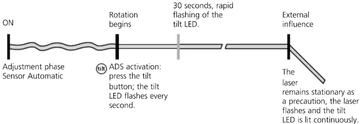
The anti-drift system (ADS) prevents erroneous or inaccurate measurements. How it works: continuous monitoring of the alignment of the laser is activated 30 seconds after the ADS is switched on. If the device moves due to the influence of external factors or the laser loses its height reference, the laser will come to a standstill. Additionally, the laser flashes and the tilt LED is lit continuously. To continue working, press the tilt button again or switch the device off then on again.

The ADS is not active following switch-on. Once the device has been set up, press the tilt button to activate the ADS. The tilt LED flashes to indicate that the ADS function is active; see the diagram below.

The ADS does not activate the monitoring function until 30 seconds after the laser levelling procedure has been completed (set-up phase).
The tilt LED flashes every second during the set-up phase, rapid flashing, when ADS is active.
ADS function
flowchart
graph LR
    A["ON"] --> B["Adjustment phase Sensor Automatic"]
    B --> C["30 seconds, rapid flashing of the tilt LED."]
    C --> D["External influence"]
    D --> E["Laser remains stationary as a precaution, laser flashes and tilt LED is lit continuously."]
    F["Rotation begins"] --> C
    G["ADS activation: press the tilt button; the tilt LED flashes every second."] --> C
Laserliner
"Lock" Transport LOCK: The device is protected by a special motor brake during transport.

The device characterised by specific protection against dustand rain.
Using the power supply / lithium-ion rechargeable battery
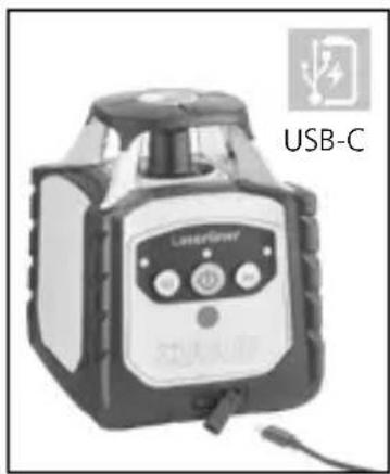
- The rechargeable battery can be charged using the 9V power supply provided or externally using the battery's integral USB-C socket and a standard USB-C power supply.
- Use the power supply/charger unit only in closed rooms; do not expose to moisture or rain otherwise risk of electric shock.
- Charge the device's battery completely prior to use.
- Connect the power pack/charger to the mains power supply and the socket in the battery pack. Please only use the power pack/charger supplied. Using any other power pack/charger will invalidate the warranty.
- While the battery is being charged when installed, the LED operating display lights up red. The LED changes to green when charging is complete.
- While the device is being charged, the LEDs flash from right to left in ascending order. Charging is complete when all three LEDs are continuously lit.
- When the battery charge level is very low, the middle LED operating display flashes first of all, and then all three LED displays together before the device switches off.
- Operation without battery: The device can be used without a battery if it is connected to the mains supply via the charging socket and the enclosed mains adapter. In this case, the middle LED operating display flashes.
natural_image
Exterior view of a LaserPower device labeled USB-C, showing control panel and sensor buttons (no readable text beyond label)
text_image
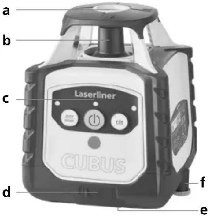
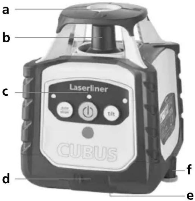
a b c Laserliner CUBUS d f ea Reference laser outlet
b Prism head / laser beam outlet
c Control panel
d Connection socket for power pack/charger
e 5/8" thread
f Battery compartment
text_image
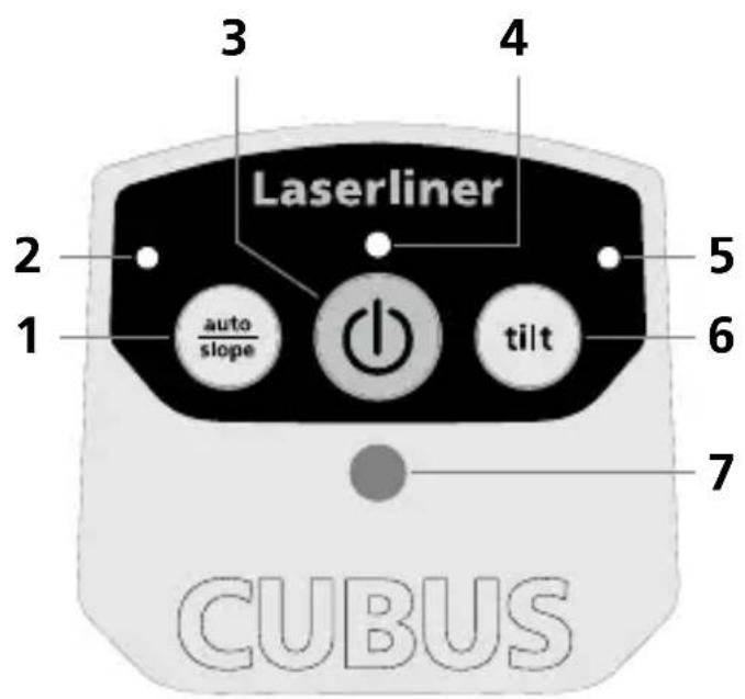
3 4 Laserliner 2 1 auto slope 5 6 tilt 7 CUBUS1 auto/slope function
2 auto/slope function LED: LED off: automatic alignment LED on: manual alignment
3 ON/OFF button
4 Operation indicator (LowBat: LED flashes)
5 Tilt function LED
6 Tilt function
7 Infrared signal receptor
Laserliner
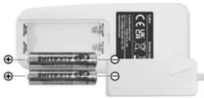
Insert batteries into the remote control
Open the battery compartment and insert batteries (2 x 1,5V LR03 (AAA)) according to the symbols. Observing the correct polarity.
natural_image
Close-up of two batteries with one partially open and the other closed, showing no visible text or symbols on the devices themselves.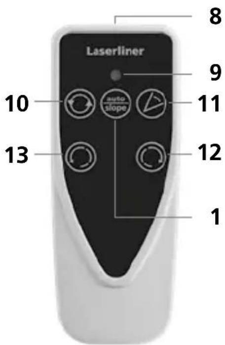
text_image
Laserliner 8 9 10 auto slope 11 12 13 18 Infrared signal emitter
9 Operation indicator
10 Rotary speed for selection 600 / 330 / 30 / 0 rpm
11 Scan mode 10^ / 45^ / 90^ / 180^
12 Positioning button (rotate to the right)
13 Positioning button (rotate to the left)
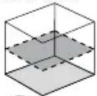
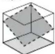
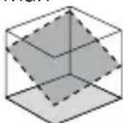
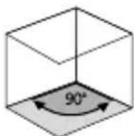
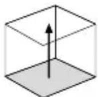
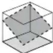
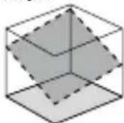
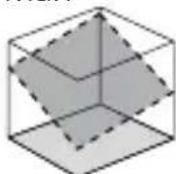
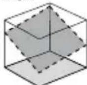
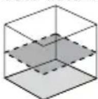
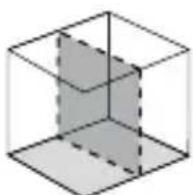
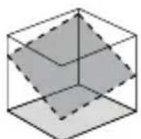
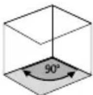
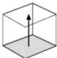
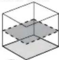
Space grids: These show the laser planes and functions.
auto: Automatic alignment / man: Manual alignment
auto auto man
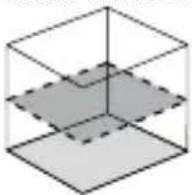
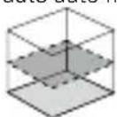
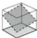
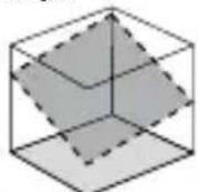
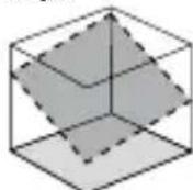
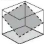
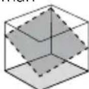
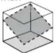
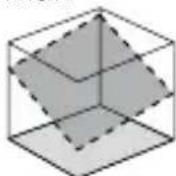
Horizontal
levelling
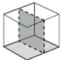
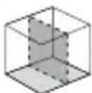
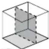
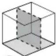
Vertical
levelling
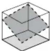
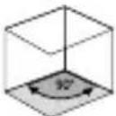
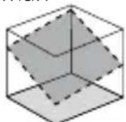
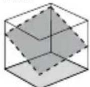
Inclined plane 90° angle 90° reference
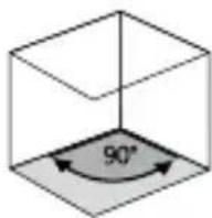
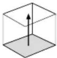
function
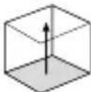
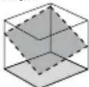
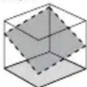
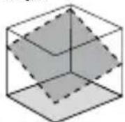
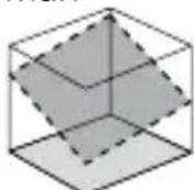
Horizontal levelling and vertical levelling
- Horizontal: Position the device on a level surface or on a tripod.
- Vertical: Place the device on its side with the stand and wall bracket fitted. The operator panel should be at the top. The device with the stand and wall bracket can be mounted on a tripod for vertical use.
- Press the „ON/OFF“ switch
auto auto
(1)
(

auto/slope function LED OFF: Automatic alignment
- The device levels itself automatically to within a range of ± 4^ . During the set-up phase, the laser flashes and the prism head remains stationary. When levelling is complete, the laser lights up continuously and rotates at maximum speed. Refer also to the sections about „Sensor Automatic“ and „ADS Tilt“.

If the device has been placed on a surface with a slope of more than 4^ , the prism head will remain stationary and the laser as well as the auto/slop LED will start to flash. The device must then be placed on a more even surface.
Slope function
Steeper slopes can be set using the angle plate, which is available as an optional extra.
TIP: Allow the device to align itself automatically and set the angle plate to the zero position. Then press the auto/slope button to switch the automatic sensor off. Finally, incline the device to the angle you require.
natural_image
Close-up of a mounted scientific instrument with a control panel and tripod base (no visible text or symbols)man
(


Auto/slope function LED ON: Manual alignment
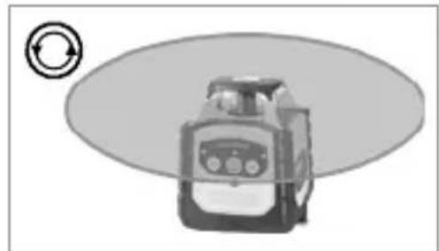
Laser modes
Rotary mode
The following speeds can be set using the rotary button: 0, 30, 330, 600 rpm
Spot mode
You access spot mode by pressing the rotary button repeatedly until the laser stops rotating. The laser can then be rotated to the required position using the positioning buttons.
Scan mode
The scan button can be used to activate and set a lightintensive segment in 4 different widths. You position the segment via the direction buttons.
Hand receiver mode
Working with the laser receiver (available as an optional extra): Set the rotary laser to maximum speed and switch on the laser receiver. Refer to the operating instructions for the respective laser receiver about this.
natural_image
Illustration of a mechanical device with a circular arrow symbol on the left (no text or labels)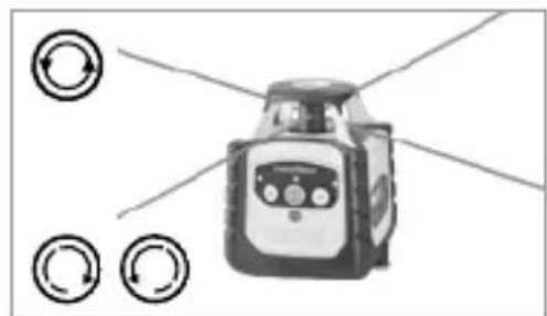
natural_image
Illustration of a robot with directional arrows indicating rotation (no text or symbols)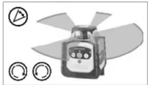
natural_image
Illustration of a propeller with three circular icons indicating rotation (no text or symbols)
natural_image
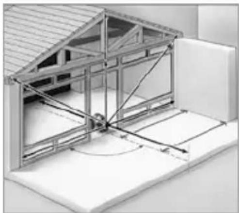
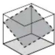
Illustration of a portable device connected to a smartphone with circular arrows indicating rotation (no text or symbols)Working with the reference laser
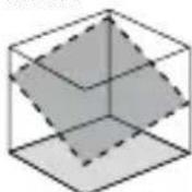
The device has one reference laser. In vertical mode the reference laser is used to align the device. Align the reference laser parallel to the wall for this purpose. This aligns the vertical laser plane at a right angle to the wall, see illustration.
natural_image
Architectural diagram of a two-story building interior with structural beams and supports (no text or symbols)Information on maintenance and care
Clean all components with a damp cloth and do not use cleaning agents, scouring agents and solvents. Remove the battery before storing for longer periods. Store the device in a clean and dry place.
Calibration
The measuring device should be calibrated and tested on a regular basis to ensure it is accurate and working properly. We recommend the measuring device is calibrated every year. If necessary, contact your distributor or the UMAREX-LASERLINER service department.
EU and UK directives and disposal
This device complies with all necessary standards for the free movement of goods within the EU and the UK.
This product, including accessories and packaging, is an electrical appliance that must be recycled in an environmentally appropriate manner in accordance with European and UK directives on waste electrical and electronic equipment, batteries and packaging, in order to recover valuable raw materials. Electrical devices, batteries and packaging do not belong in household waste. Users are obliged by law to surrender used batteries or battery packs to a public collection point, to sales outlets, or to technical customer services, free of charge. Remove the battery from the device without damaging it using standard commercial tools: arrange separate collection before returning the device for disposal. Please do not hesitate to contact the UMAREX-LASERLINER service department if you have any queries regarding removing the battery. Look for information on local disposal facilities and note the relevant disposal and safety information at the collection points.
Further safety and supplementary notices at:
Cubus: https://packd.li/II/ANM/in
Cubus Green: https://packd.li/ll/APV/in
| Technical data (Subject to technical alterations. 24W43) | |
| Self-levelling range ± 4° | |
| Accuracy ± 0.15 mm / m | |
| Levelling | automatic horizontal / vertical levelling with electronic levels and motors |
| Self-levelling alignment time | approx. 30 seconds over the entire operating angle |
| Rotation speed 0, 30, 330, 600 rpm | |
| Laser wavelengths Reference beam red / green | 635 nm / 515 nm |
| Laser class | 2 / < 1 mW (EN 60825-1:2014/A11:2021 / EN 50689:2021) |
| Power supply Li-ion battery pack | 7.4V / 2.6Ah / 19.24Wh |
| Operating time red / green approx. 25 h | |
| Charging time approx. 4 h | |
| Operating conditions | -10°C ... 50°C, max. humidity 80% rH, no condensation, max. working altitude 4000 m above sea level |
| Storage conditions | -10°C ... 70°C, max. humidity 80% rH |
| Protection class IP 66 | |
| Dimensions (W x H x D) | 130 x 160 x 145 mm (with stand and wall bracket) |
| Weight 1300 g (with stand and wall bracket) | |
| Remote control | |
| Power supply 2 x 1.5V LR03 (AAA) | |
| Remote control range max. 30 m (IR-control) | |
| Weight 70 g (incl. batteries) | |
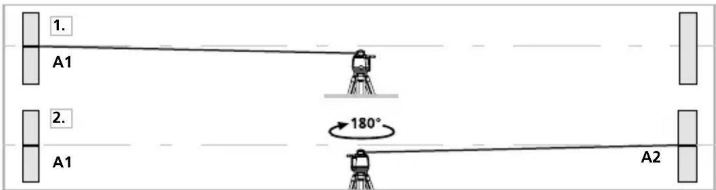
Preparing the calibration check
It is possible for you to check the calibration of the laser. To do this, position the device midway between 2 walls, which must be at least 5 metres apart. Switch the device on. The best calibration results are achieved if the device is mounted on a tripod. IMPORTANT: The automatic sensor must be active (auto/slope LED is off).
- Mark point A1 on the wall.
- Turn the device through 180^ and mark point A2. You now have a horizontal reference between points A1 and A2.
text_image
1. A1 2. A1 180° A2Performing the calibration check
- Position the device as near as possible to the wall at the height of point A1. Now adjust the device in the X axis.
- Turn the device through 180^ and mark point A3. The difference between points A2 and A3 is the tolerance for the X axis.
- To check the Y and Z axis, repeat steps 3 and 4.

text_image
3. A1 4. 180° <0,15 mm / m = OK A2 A3 A2 A3
If points A2 and A3 are more than 0.15 mm / m apart on either the X or Y axis, the device is in need of adjustment. Contact your authorised dealer or else the UMAREX-LASERLINER Service Department.
!
text_image
Warning sign with sunburst symbol inside triangle, commonly used in safety or hazard warningnatural_image
Exterior view of a Laseraser device labeled USB-C, showing control panel and speaker grille (no readable text beyond label)Laserliner
text_image
a b c Laserliner CUBUS d f e Jute lift Tiltnatural_image
Close-up of two batteries with one partially open and the other closed, no visible text or symbols on the main components.
text_image
Laserliner 8 9 10 auto slope 11 12 1 13natural_image
3D wireframe diagram of a cube with shaded internal planes (no text or symbols)natural_image
Close-up of a precision optical instrument with adjustable arm and control panel (no visible text or symbols)man

(

natural_image
Illustration of a mechanical device with a circular arrow symbol on the left (no text or labels)Puntmodus
natural_image
Illustration of a robot with directional arrows indicating rotation or signal flow (no text or symbols)Scanmodus
natural_image
Illustration of a propeller with four blades and control buttons (no text or symbols)Handontvanger-Modus
natural_image
Illustration of a portable device and a smartphone with circular arrows indicating rotation (no text or symbols)natural_image
Architectural cross-section diagram of a building facade with structural beams and supports (no text or symbols)Cubus Green: https://packd.li/ll/APV/in
text_image
3. A1 4. 180° ≤0,15 mm / m = OK A2 A3 A2 A3
natural_image
Warning symbol with a triangular triangle and central sunburst pattern (no text)natural_image
Exterior view of a LaserFilter device labeled USB-C, showing control panel and power cord (no readable text beyond label)
text_image
a b c Laserliner CUBUS d f enatural_image
Close-up of two batteries with one partially open and the other closed, showing battery labels and polarity indicators (no readable text or symbols)
text_image
Laserliner 8 9 10 auto slope 11 12 13 1natural_image
Close-up of a mounted scientific instrument with control panel and tripod base (no visible text or symbols)man
(


LED auto/slope-funktion lyser: Manuel indjustering
Lasermodi
Rotations-modus
natural_image
Illustration of a mechanical device with a circular arrow symbol on the left (no text or labels)
natural_image
Illustration of a robot with four circular arrows pointing outward from it, no text or symbols present.
natural_image
Illustration of a propeller with four blades and control buttons (no text or symbols)
natural_image
Illustration of a device with a circular arrow symbol, next to a smartphone displaying a screen (no text or symbols present)natural_image
Architectural diagram of a roof structure with steel framework and structural beams (no text or symbols)Cubus Green: https://packd.li/ll/APV/in
text_image
Warning sign with sunburst symbol inside triangle, commonly used for safety or hazard warningnatural_image
Close-up of two batteries with one partially open and the other closed, showing no visible text or symbols on the devices themselves.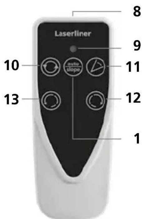
text_image
Laserliner 8 9 10 auto slope 11 12 13 1natural_image
Close-up of a mounted optical instrument with control panel and tripod stand (no visible text or symbols)man
(


natural_image
Illustration of a mechanical device with a circular arrow symbol on the left (no text or labels)Mode Point
natural_image
Diagram of a robot with directional arrows indicating rotation, no text or symbols presentMode Scanner
natural_image
Illustration of a propeller with four blades and control buttons (no text or symbols)natural_image
Illustration of a device with a circular arrow symbol, next to a smartphone displaying a screen (no text or symbols present)natural_image
Architectural diagram of a roof structure with steel framework and structural beams (no text or symbols)Cubus Green: https://packd.li/ll/APV/in
text_image
Warning sign with sunburst symbol inside triangle, commonly used for safety or hazard warningnatural_image
Exterior view of a LaserFilter device with control buttons and a USB-C label (no readable text beyond branding)
text_image
a b c Laserliner CUBUS d f enatural_image
Close-up of two batteries with one partially open and the other closed, showing battery labels and polarity indicators (no readable text or symbols)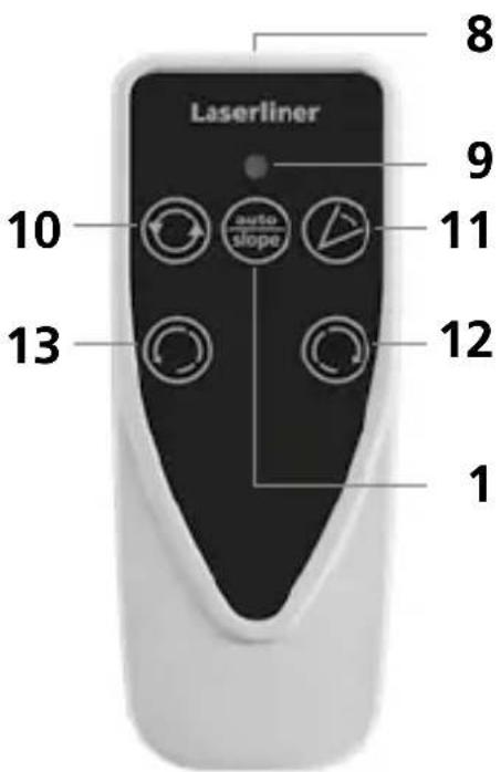
text_image
Laserliner 8 9 10 auto slope 11 13 12 1natural_image
Close-up of a mounted scientific instrument with control lever and display panel (no visible text or symbols)man
(


natural_image
Illustration of a mechanical device with a circular arrow symbol on the left (no text or labels)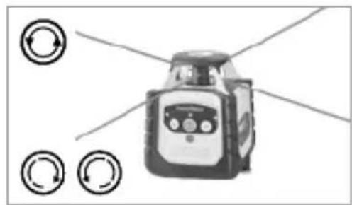
natural_image
Illustration of a robot with circular arrows pointing outward from it, no text or symbols present.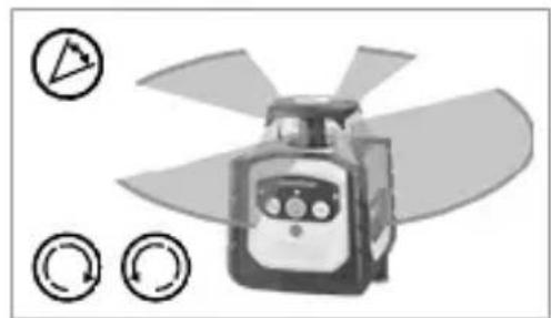
natural_image
Illustration of a propeller with four blades and control buttons (no text or symbols)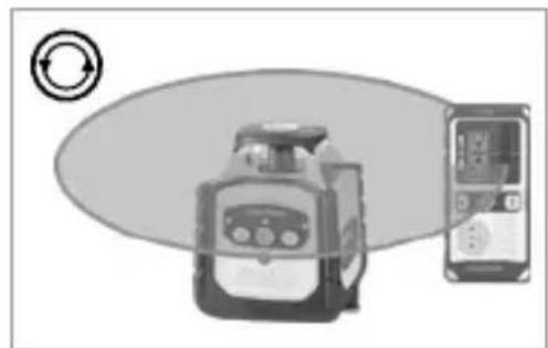
natural_image
Illustration of a device with a circular arrow symbol and a separate smartphone displaying a screen (no text or symbols present)natural_image
Architectural cross-section diagram of a building facade with structural beams and framing (no text or symbols)Cubus Green: https://packd.li/ll/APV/in
text_image
Warning sign with sunburst symbol inside triangle, commonly used in safety or hazard prevention context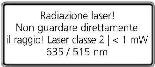
natural_image
Exterior view of a LaserMeter device labeled USB-C, showing control panel and power button (no readable text beyond label)Laserliner

text_image
a b c Laserliner CUBUS d f enatural_image
Close-up of two batteries with one labeled 'ZHXALINE' and the other a CDK card (no visible text or symbols on the devices themselves)
text_image
Laserliner 8 9 10 auto slope 11 12 13 1natural_image
3D wireframe diagram of a cube with shaded faces (no text or symbols)Livellamento verticale
natural_image
Close-up of a handheld industrial sensor or pressure meter device with no visible text or symbolsman
(


natural_image
Illustration of a mechanical device with a circular arrow symbol on the left (no text or labels)natural_image
Illustration of a robot with directional arrows and circular indicators (no text or symbols)Modalità scan
natural_image
Illustration of a propeller with four blades and three circular control buttons below (no text or symbols)natural_image
Illustration of a portable device and a smartphone with circular arrows indicating rotation (no text or symbols)natural_image
Architectural diagram of a steel-framed building structure with internal beams and supports (no text or symbols)Cubus Green: https://packd.li/ll/APV/in
text_image
3. A1 4. 180° ≤0,15 mm / m = OK A2 A3 A2 A3
natural_image
Warning symbol with a triangular frame and central sunburst pattern (no text)natural_image
Exterior view of a LaserFilter device labeled USB-C, showing control panel and ports (no readable text beyond label)
text_image
a b c Laserliner CUBUS d f enatural_image
Close-up of two batteries with one partially open and the other closed, showing no visible text or symbols on the devices themselves.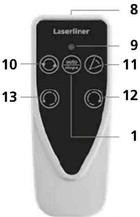
text_image
Laserliner 8 9 10 auto slope 11 13 12 1natural_image
Close-up of a handheld scientific instrument with a mounted probe and control lever (no visible text or symbols)man

(


natural_image
Illustration of a device with circular arrow symbol (no text or labels)Tryb punktowy
natural_image
Illustration of a robot with circular arrows pointing outward from it, no text or symbols present.Tryb skanowania
natural_image
Illustration of a propeller with blades and control buttons (no text or symbols)natural_image
Illustration of a device with a circular arrow symbol and a smartphone displaying a screen (no text or symbols present)natural_image
Architectural cross-section diagram of a roof structure with structural framework (no text or labels)Cubus Green: https://packd.li/ll/APV/in
text_image
Warning sign with triangular shape containing a central sunburst symbolnatural_image
Exterior view of a LaserPower device labeled USB-C, showing control panel and power cord (no readable text beyond label)Laserliner

text_image
a b c Laserliner CUBUS d f enatural_image
Close-up of a white cylindrical battery with two 200-pin batteries and one 100-pin CD card, showing polarity indicators (no text or symbols on the main components)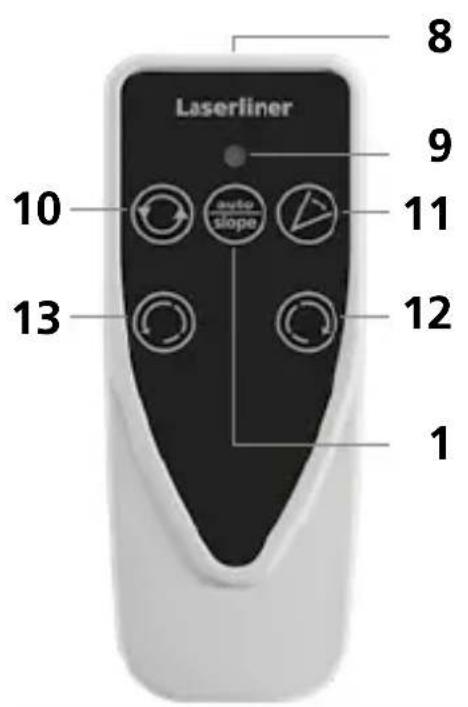
text_image
Laserliner 10 auto slope 13 12 9 8natural_image
Close-up of a mounted optical instrument with control panel and tripod base (no visible text or symbols)man
(


natural_image
Illustration of a mechanical device with circular arrow symbol (no text or labels)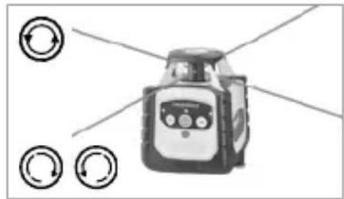
natural_image
Illustration of a robot with directional arrows indicating rotation or signal flow (no text or symbols)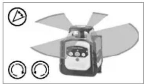
natural_image
Illustration of a propeller with fan blades and control buttons (no text or symbols)
natural_image
Illustration of a device with a circular arrow symbol, next to a smartphone displaying a screen (no text or symbols present)natural_image
Architectural cross-section diagram of a building facade with structural beams and supports (no text or symbols)Cubus Green: https://packd.li/ll/APV/in
natural_image
Warning symbol with a triangular triangle containing a central starburst (no text or numbers)natural_image
Product photo of a LaserPower device labeled USB-C, showing control panel and speaker grille (no readable text beyond label)
text_image
a b c Laserliner CUBUS d f enatural_image
Close-up of two batteries with one partially open and the other closed, showing model numbers and polarity indicators (no readable text or symbols)
text_image
Laserliner 8 9 10 auto slope 11 12 13 1natural_image
Close-up of a mounted scientific instrument with control panel and tripod base (no visible text or symbols)man
(


natural_image
Illustration of a device with a circular arrow symbol on the left (no text or labels)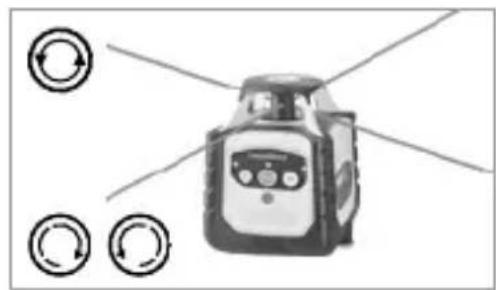
natural_image
Illustration of a robot with circular arrows pointing outward from it, no text or symbols present.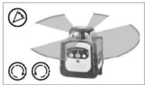
natural_image
Illustration of a propeller with blades and control buttons (no text or symbols)
natural_image
Illustration of a portable device and a smartphone with circular arrows indicating rotation (no text or symbols)natural_image
Architectural cross-section diagram of a roof structure with structural framework (no text or labels)Cubus Green: https://packd.li/ll/APV/in
text_image
Warning sign with triangular shape containing a central sunburst symbolLaserstrålning! Titta aldrig direkt in i laserstrålen! Laser klass 2 | < 1 mW 635 / 515 nm
EN 60825-1:2014/A11:2021 / EN 50689:2021
natural_image
Exterior view of a LaserMeter device labeled USB-C, showing control panel and power button (no readable text beyond label)Laserliner
text_image
a b c Laserliner CUBUS d f enatural_image
Close-up of a white cylindrical battery with two 200-pin batteries and a black CEPB card, showing polarity indicators (no text or symbols on the main components)
text_image
Laserliner 8 9 10 11 12 13 1natural_image
3D wireframe diagram of a cube with shaded faces (no text or symbols)Vertikal nivellering
Lutande plan 90° vinkel 90° referens-
funktion
Laserliner
natural_image
Close-up of a handheld industrial sensor or pressure meter device with no visible text or symbolsman
(


Lysdiod auto/slope-funktion tänd: Manuell injustering
Laserlägen
Rotationsläge
natural_image
Illustration of a mechanical device with circular arrow symbol (no text or labels)Punktläge
natural_image
Illustration of a robot with circular arrows pointing outward from it, no text or symbols present.Skanningsläge
natural_image
Illustration of a propeller with blades and control buttons (no text or symbols)Handmottagarläge
natural_image
Illustration of a device with a circular arrow symbol and a smartphone displaying a screen (no text or symbols present)natural_image
Architectural cross-section diagram of a roof structure with structural framework (no text or labels)Cubus Green: https://packd.li/ll/APV/in
text_image
3. A1 4. 180° ≤0,15 mm / m = OK A2 A3 A2 A3
natural_image
Warning symbol with a triangular frame and central sunburst pattern (no text)Laserstråling! Ikke se inn i strålen! Laser klasse 2 | < 1 mW 635 / 515 nm
EN 60825-1:2014/A11:2021 / EN 50689:2021
natural_image
Exterior view of a LaserCover device labeled USB-C, showing control panel and sensor buttons (no readable text beyond label)
text_image
a b c Laserliner CUBUS d f etext_image
Cp Alkaline CD48 Color Magnetic Card
text_image
Laserliner 8 9 10 auto slope 11 12 13 1natural_image
Close-up of a mounted optical instrument with control panel and display unit (no visible text or symbols)man
(


natural_image
Illustration of a device with circular arrow symbol (no text or labels)
natural_image
Illustration of a robot with directional arrows indicating rotation or signal flow (no text or symbols)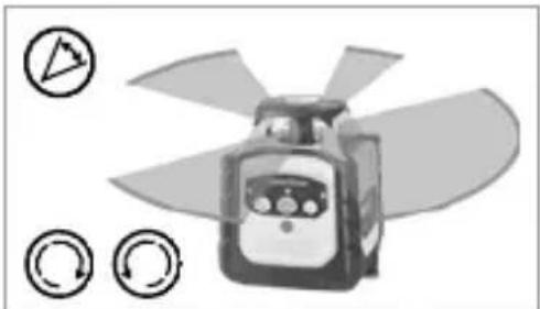
natural_image
Illustration of a propeller with four blades and circular control buttons (no text or symbols)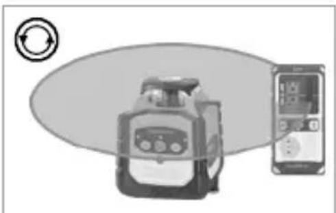
natural_image
Illustration of a portable device and a smartphone with circular arrows indicating rotation (no text or symbols)Arbeide med referanselaseren
natural_image
Architectural cross-section diagram of a roof structure with structural framework (no text or labels)Cubus Green: https://packd.li/ll/APV/in
| Tekniske data (Det tas forbehold om tekniske endringer. 24W43) | |
| Selvnivelleringsområde ± 4° | |
| Nøyaktighet ± 0,15 mm / m | |
| Nivellering | horisontal / vertikal automatisk med elektroniske vaterpass og servomotorer |
| Innstillingshastighet ca. 30 Sek. over | hele arbeidsvinkelen |
| Rotasjonsturtall 0, 30, 330, 600 o/min | |
| LaserbølgelengdeReferansestråle rød / grønn | 635 nm / 515 nm |
| Laserklasse | 2 / < 1 mW (EN 60825-1:2014/A11:2021 / EN 50689:2021) |
| Strømforsyning | Li-lon batteripakke 7,4V / 2,6Ah / 19,24Wh |
| Driftsvarighet rød / grønn ca. 25 timer | |
| Ladetid ca. 4 timer | |
| Arbeidsbetingelser | -10°C ... 50°C, luftfuktighet maks. 80% rH, ikke kondenserende, arbeidshøyde maks. 4000 m.o.h. |
| Lagringsbetingelser | -10°C ... 70°C, luftfuktighet maks. 80% rH |
| Beskyttlsesart IP 66 | |
| Mål (B x H x D) | 130 x 160 x 145 mm(med stativ- og veggholder) |
| Vekt 1300 g (med stativ- og veggholder) | |
| Fjernbetjening | |
| Strømforsyning 2 x 1,5V LR03 (AAA) | |
| Rekkevidde fjernbetjening maks. 30 | m (IR-control) |
| Vekt 70 g (inkl. batterier) | |
text_image
3. A1 4. 180° ≤0,15 mm / m = OK A2 A3 A2 A3
text_image
Warning sign with triangular shape containing a central sunburst symbolnatural_image
Exterior view of a LaserTimer device labeled USB-C, showing control panel and power cord (no readable text beyond label)Laserliner

text_image
a b c Laserliner CUBUS d f enatural_image
Close-up of two batteries with charging caps, one labeled 'AXALINE' and the other a CD card (no visible text beyond labels)
text_image
Laserliner 8 9 10 11 12 13 1natural_image
Close-up of a precision optical instrument with mounted components (no visible text or symbols)man
(


natural_image
Illustration of a device with circular arrow symbol (no text or labels)
natural_image
Illustration of a robot with directional arrows indicating rotation or signal flow (no text or symbols)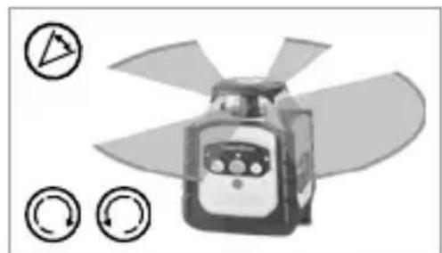
natural_image
Illustration of a propeller with blades and control buttons (no text or symbols)
natural_image
Illustration of a portable device with a circular icon and a smartphone displaying a screen, no text or symbols present.natural_image
Architectural cross-section diagram of a building facade with structural beams and supports (no text or symbols)Cubus Green: https://packd.li/ll/APV/in
natural_image
Warning symbol with a triangular frame and central sunburst pattern (no text)natural_image
Exterior view of a LaserPower device labeled USB-C, showing control panel and power button (no readable text beyond label)natural_image
Close-up of two batteries with one labeled 'HYALINE' and the other a CD49 card, showing no visible text or symbols on the devices themselves.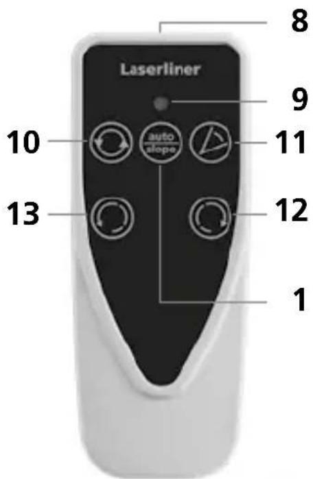
text_image
Laserliner 1 8 9 10 auto slope 11 12 13 1natural_image
Close-up of a mounted optical instrument with control panel and tripod base (no visible text or symbols)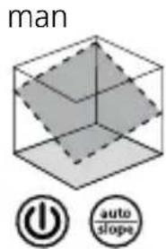
text_image
man power auto slopesnatural_image
Illustration of a device with a circular arrow symbol on the left (no text or labels)natural_image
Illustration of a robot with directional arrows and circular indicators (no text or symbols)Режим сканирования
natural_image
Illustration of a propeller with four blades and circular control buttons (no text or symbols)natural_image
Illustration of a portable device connected to a smartphone with circular arrows indicating rotation (no text or symbols)natural_image
Architectural diagram of a roof structure with steel framework and structural beams (no text or symbols)Cubus Green: https://packd.li/ll/APV/in
text_image
Warning sign with triangular triangle and central sunburst symbolnatural_image
Product photo of a LaserTimer device labeled USB-C, showing control panel and sensor buttons (no readable text beyond label)Laserliner

text_image
a b c Laserliner CUBUS d f enatural_image
Close-up of a white cylindrical battery with two black lithium-ion batteries, one labeled 'Cable' and the other 'Electric C'.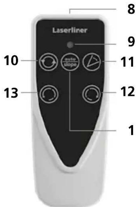
text_image
Laserliner 8 9 10 auto slope 11 13 12 1natural_image
Close-up of a mounted scientific instrument with control panel and tripod base (no visible text or symbols)man
(

natural_image
Illustration of a mechanical device with a circular arrow symbol on the left (no text or labels)Точковий режим
natural_image
Illustration of a robot with directional arrows indicating rotation or signal flow (no text or symbols)Віяловий режим
natural_image
Illustration of a propeller with four blades and control buttons (no text or symbols)natural_image
Illustration of a kitchen appliance and a smartphone with circular arrows indicating rotation (no text or symbols)natural_image
Architectural cross-section diagram of a building facade with structural framework and structural elements (no text or symbols)Cubus Green: https://packd.li/ll/APV/in
text_image
3. A1 4. 180° ≤0.15 mm / m = OK A2 A3 A2 A3
natural_image
Warning symbol with a triangular triangle and central sunburst pattern (no text)natural_image
Exterior view of a LaserFilter device labeled USB-C, showing control panel and sensor buttons (no readable text beyond label)
text_image
a b c Laserliner CUBUS d f enatural_image
Close-up of two batteries with one partially open and the other closed, showing battery design (no text or symbols visible)
text_image
Lasertiner 8 9 10 auto slope 11 13 12 1natural_image
Close-up of a black and white scientific instrument with control panel and tripod base (no visible text or symbols)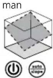
text_image
man power auto slope
natural_image
Illustration of a mechanical device with a circular arrow symbol on the left (no text or labels)Bodový režim
natural_image
Illustration of a robot with directional arrows indicating rotation or signal flow (no text or symbols)Skenovací režim
natural_image
Illustration of a propeller with four blades and control buttons (no text or symbols)natural_image
Illustration of a portable device connected to a smartphone with circular arrows indicating refresh or sync (no text or symbols)natural_image
Architectural cross-section diagram of a building facade with structural beams and supports (no text or symbols)Cubus Green: https://packd.li/ll/APV/in
text_image
Warning sign with triangular shape containing a central sunburst symbolLaserkiirgus! Mitte vaadata laserikiirt! Laseriklass 2 | < 1 mW 635 / 515 nm
EN 60825-1:2014/A11:2021 / EN 50689:2021
natural_image
Exterior view of a LaserPower device labeled USB-C, showing control panel and power button (no readable text beyond label)Laserliner

text_image
a b c Laserliner CUBUS d f ea Referentslaseri väljund
natural_image
Close-up of a white cylindrical battery with two red batteries and a black CECB card, showing polarity indicators (no text or symbols on the main components)
text_image
Laserliner 8 9 10 11 12 13 1natural_image
3D wireframe diagram of a cube with shaded internal planes (no text or symbols)natural_image
Close-up of a handheld scientific instrument with control panel and tripod stand (no visible text or symbols)man
(

natural_image
Architectural diagram of a roof structure with steel framework and structural beams (no text or symbols)Cubus Green: https://packd.li/ll/APV/in
text_image
Warning sign with sunburst symbol inside triangle, commonly used in safety or hazard prevention contextnatural_image
Simple wavy line diagram with two vertical bars on both sides (no text or symbols)Faza de setare Senzor Automatic
text_image
USB-C LED/Power 100% 100%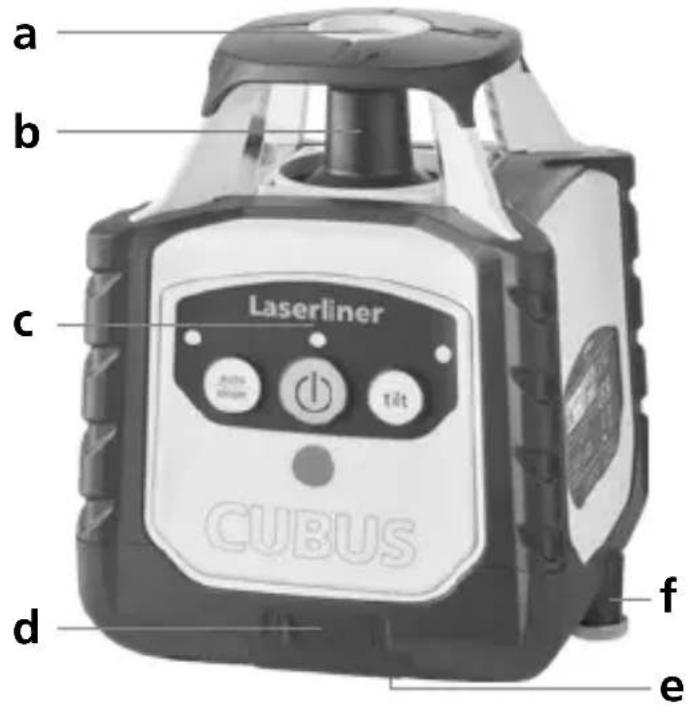
text_image
a b c Laserliner CUBUS d f enatural_image
Close-up of two batteries with one labeled 'Cer 200' and the other showing a CD49 card (no text on batteries or background)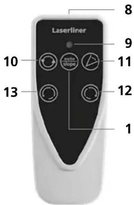
text_image
Laserliner 8 9 10 auto slope 11 12 13 1natural_image
Close-up of a laboratory instrument with control panel and mechanical arm (no visible text or symbols)man
(


natural_image
Illustration of a mechanical device with a circular arrow symbol on the left (no text or labels)Modul punctiform
natural_image
Illustration of a robot with four circular arrows pointing outward from it, no text or symbols present.Modul scanare
natural_image
Illustration of a propeller with four blades and control buttons (no text or symbols)Modul de receptor manual
natural_image
Illustration of a device connected to a smartphone with circular arrows indicating rotation (no text or symbols)natural_image
Architectural diagram of a building interior with structural beams and supports (no text or symbols)Cubus Green: https://packd.li/ll/APV/in
natural_image
Warning symbol with a triangular triangle and central starburst (no text or numbers)natural_image
Simple wavy line diagram with a vertical bar on the left (no text or symbols)natural_image
Exterior view of a LaserTimer device labeled USB-C, showing control panel and sensor buttons (no readable text beyond label)Laserliner

text_image
a b c Laserliner CUBUS d f e(2 × 1,5V LR03 (AAA)) според
natural_image
Close-up of two batteries with one partially open and the other closed, showing no visible text or symbols on the devices themselves.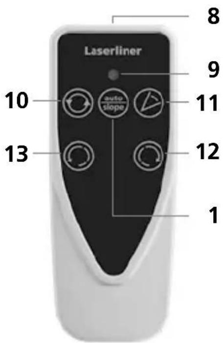
text_image
Laserliner 1 13 10 auto slope 9 8 12natural_image
Close-up of a precision optical instrument with adjustable arm and control panel (no visible text or symbols)man
(

natural_image
Illustration of a mechanical device with a circular arrow symbol on the left (no text or labels)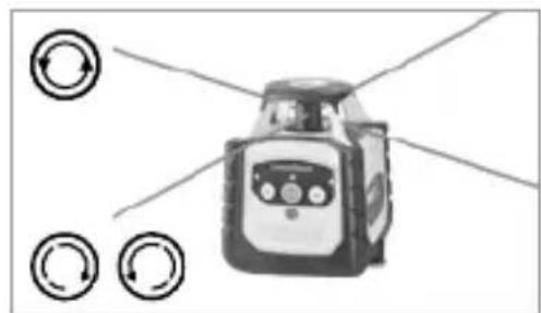
natural_image
Illustration of a robot with directional arrows indicating rotation or signal flow (no text or symbols)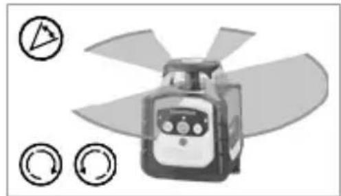
natural_image
Illustration of a propeller with four blades and control buttons (no text or symbols)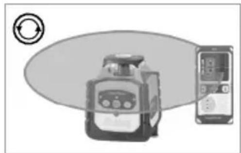
natural_image
Illustration of a device with a circular arrow symbol and a smartphone displaying a screen (no text or labels)natural_image
Architectural diagram of a building interior with structural beams and supports (no text or symbols)Cubus Green: https://packd.li/ll/APV/in
natural_image
Warning symbol with a triangular triangle and central sunburst (no text or numbers)natural_image
Exterior view of a LaserEaser device labeled USB-C, showing control panel and sensor buttons (no readable text beyond label)
text_image
a b c Laserliner CUBUS d f enatural_image
Close-up of two batteries with one partially open and the other closed, showing battery design (no text or symbols visible)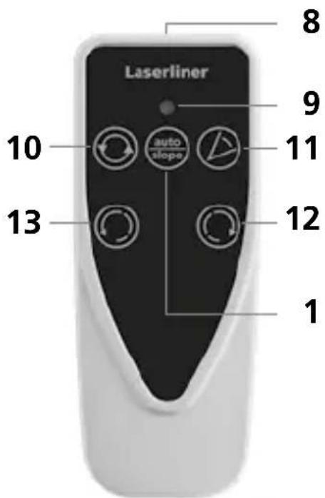
text_image
Laserliner 1 8 9 10 auto slope 11 12 13 1natural_image
Close-up of a mounted scientific instrument with control panel and tripod base (no visible text or symbols)man
(


natural_image
Illustration of a robot with a circular arrow symbol on the left (no text or labels)natural_image
Illustration of a robot with directional arrows indicating rotation or signal flow (no text or symbols)Λειτουργία σάρωσης
natural_image
Illustration of a propeller with three circular icons indicating rotation or refresh (no text or symbols)natural_image
Illustration of a portable device and a smartphone with circular arrows indicating rotation (no text or symbols)natural_image
Architectural diagram of a structural frame with beams and supports, no visible text or symbolsCubus: https://packd.li/ll/ANM/in
Cubus Green: https://packd.li/ll/APV/in
text_image
Warning sign with sunburst symbol inside triangle, commonly used in safety or hazard prevention contextnatural_image
Exterior view of a LaserRiver device labeled USB-C, showing control panel and buttons (no readable text beyond label)Laserliner

text_image
a b c Laserliner CUBUS d f enatural_image
Close-up of two batteries with one labeled 'ZHXALINE' and the other a CDK card (no visible text or symbols on the devices themselves)
text_image
Laserliner 8 9 10 auto slope 11 12 13 18 Izhod infrardečega signala
9 Prikaz delovanja
10 Izbira hitrosti vrtenja
600 / 330 / 30 / 0 vrt/min
11 Način skeniranja
10° / 45° / 90° / 180°
12 Gumb za pozicioniranje (zasuk v desno)
13 Gumb za pozicioniranje (zavrtite v levo)
Mreže za prostore: Na njih so prikazani nivoji in funkcije laserja.
natural_image
Close-up of a precision optical instrument with adjustable lens and tripod base (no visible text or symbols)man
(

natural_image
Architectural cross-section diagram of a building facade with structural beams and framing (no text or symbols)Laserski načini
Način vrtenja
natural_image
Illustration of a portable device with a circular arrow symbol on the left (no text or symbols present)Točkovni način
natural_image
Illustration of a robot with directional arrows and circular indicators (no text or symbols)Način skeniranja
natural_image
Illustration of a propeller with four blades and three circular icons below (no text or symbols)natural_image
Illustration of a portable device and a handheld device with circular arrow symbol (no text or labels)Cubus Green: https://packd.li/ll/APV/in
text_image
Warning sign with sunburst symbol inside triangle, commonly used in safety or hazard prevention contextnatural_image
Exterior view of a LaserPower device labeled USB-C, showing control panel and ports (no readable text beyond label)
text_image
a b c Laserliner CUBUS d f enatural_image
Close-up of a mounted scientific instrument with control panel and tripod base (no visible text or symbols)man
(


natural_image
Architectural diagram of a roof structure with steel framework and structural beams (no text or symbols)Lézermódok
Forgatási mód
natural_image
Illustration of a robot with a circular arrow symbol on the left (no text or symbols present)Pont üzemmód
natural_image
Illustration of a robot with directional arrows and circular indicators (no text or symbols)Letapogatás üzemmód
natural_image
Illustration of a propeller with four blades and three circular icons below (no text or symbols)Kézi vevő üzemmód
natural_image
Illustration of a portable device and a handheld device with circular arrow symbol (no text or labels)Cubus: https://packd.li/ll/ANM/in
Cubus Green: https://packd.li/ll/APV/in
text_image
Warning sign with sunburst symbol inside triangle, commonly used in safety or hazard prevention contextnatural_image
Exterior view of a LaserRaser device labeled USB-C, showing control panel and buttons (no readable text beyond label)Laserliner

text_image
a b c Laserliner CUBUS d f enatural_image
Close-up of two batteries with one labeled 'ZHXALINE' and the other a CDK card, showing no visible text or symbols on the devices themselves.
text_image
Laserliner 10 auto slope 13 12 8 9 11text_image
man power auto slopenatural_image
Architectural cross-section diagram of a building facade with structural framework (no text or symbols)Režimy lasera
Režim otáčania
natural_image
Illustration of a portable device with a circular arrow symbol on the left (no text or labels)Bodový režim
natural_image
Illustration of a robot with directional arrows indicating rotational flow (no text or symbols)Režim skenovania
natural_image
Illustration of a propeller with four blades and three circular icons below (no text or symbols)natural_image
Illustration of a device with a circular arrow symbol and a separate screen showing a device with a display (no text or symbols present)Cubus Green: https://packd.li/ll/APV/in
natural_image
Warning symbol with a triangular triangle and central sunburst (no text or numbers)Lasersko zračenje! Ne gledati u lasersku zraku! Laser klase 2 < 1 mW · 635 / 515 nm
EN 60825-1:2014/A11:2021 / EN 50689:2021
natural_image
Exterior view of a LaserPower device labeled USB-C, showing control panel and wiring (no readable text beyond label)
text_image
a b c Laserliner CUBUS d f ea Izlaz referentnog lasera
b Glava prizme / izlaz laserske zrake
c Upravljačko polje
d Priključnica za mrežni adapter / punjač
e 5/8" navoj
f Pretinac za baterije

text_image
3 4 Laserliner 2 1 auto slope 5 6 tilt 7 CUBUS1 Funkcije auto/slope
2 LED funkcije auto/slope:
Isključen LED: Automatsko
niveliranje
Uključen LED: Ručno niveliranje
3 Tipka UKLJ./ISKLJ.
4 Indikator rada
(LowBat: treperi LED)
5 LED indikator funkcije naginjanaj
6 Funkcija naginjanja
7 Polje prijama infracrvenog signala
Laserliner
natural_image
Close-up of two batteries with one partially open and the other closed, showing no visible text or symbols.
text_image
Laserliner 8 9 10 auto slope 11 12 13 18 Izlaz infracrvenog signala
9 Indikator rada
10 Odabir brzine rotacije 600 / 330 / 30 / 0 o/min
11 Modus skeniranja
10° / 45° / 90° / 180°
12 Tipka za pozicioniranje (zakretanje udesno)
13 Tipka za pozicioniranje (zakretanje ulijevo)
Prostorna rešetka: Ona naznačuje razine lasera i funkcije.
Auto: Automatsko niveliranje / Man: Ručno niveliranje
auto auto man
Vodoravno
niveliranje
Okomito
niveliranje
Kosa ravnina Kut od 90°
Funkcija
referentnog
kuta od 90°
Vodoravno i okomito niveliranje
– Vodoravno: Postavite uređaj na što ravnijoj površini ili ga pričvrstite na stativu.
- Okomito: Stavite uređaj s montiranim stativnim i zidnim držačem na stranu. Upravljačko polje pokazuje prema gore. Pomoću stativnog i zidnog držača uređaj se u okomitoj primjeni može montirati na stativu.
– Pritisnite tipku UKLJ./ISKLJ.
auto auto
(1)
(1)

Isključen LED funkcije auto/slope: Automatsko niveliranje
- Uređaj se automatski nivelira u rasponu od ± 4°. U fazi namještanja laser treperi, a glava prizme miruje. Kad se izvrši niveliranje, laser stalno svijetli i rotira na maksimalnom broju okretaja. U vezi s time pogledajte i odlomak „Senzorska automatika“ i „ADS naginjanje“.

Ako je uređaj postavljen prekoso (pod kutom većim od 4°), glava prizme miruje, a laser i LED funkcije auto/slope trepere. Uređaj je tada potrebno postaviti na ravnijoj površini.
Funkcija naginjanja
Veći nagibi mogu se ostvariti korištenjem opcionalnog kutnog nosača. SAVJET: Najprije pustite uređaj da se automatski nivelira i zatim postavite kutni nosač na nulu. Zatim pomoću tipke auto/slope-isključite senzorsku automatiku. Nakon toga nagnite uređaj pod željenim kutom.
natural_image
Close-up of a mounted scientific instrument with control panel and tripod base (no visible text or symbols)man
(
auto slope

Uključen LED funkcije auto/slope: ručno niveliranje
Laserliner
Modusi lasera
Modus rotacije
Pomoću tipke za rotaciju namještaju se brojevi okretaja: 0, 30, 330, 600 o/min
Punktualni modus
Kako biste dospjeli u punktualni modus, pritišćite tipku za rotaciju sve dok laser ne prestane rotirati. Laser je moguće zakrenuti u željeni položaj pomoću tipki za pozicioniranje.
Modus skeniranja
Pomoću tipke za skeniranje moguće je aktivirati i namjestiti neki segment intenzivnog svjetla u 4 različite širine. Segment se u željeni položaj zakreće korištenjem tipki za pozicioniranje.
natural_image
Illustration of a device with a circular arrow symbol on the left (no text or labels)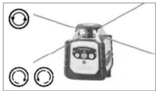
natural_image
Illustration of a robot with directional arrows and circular indicators (no text or symbols)
natural_image
Illustration of a propeller with blades and control buttons (no text or symbols)
natural_image
Illustration of a portable device and a handheld electronic device with circular arrow symbol (no text or labels)Rad s referentnim laserom
Uređaj raspolaže referentnim laserom. Kod rada u okomitom položaju referentni laser služi za niveliranje uređaja. U tu svrhu fino namjestite referentni laser paralelno sa zidom. Okomita ravnina lasera tada je usmjerena okomito na zid; pogledajte sliku.

natural_image
Architectural cross-section diagram of a roof structure with structural framework (no text or labels)Cubus Green: https://packd.li/ll/APV/in
| Tehnički podaci(Zadržavamo pravo na tehničke izmjene bez prethodne najave. 24W43) | |
| Raspon samoniveliranja ± 4° | |
| Točnost ± 0,15 mm / m | |
| Niveliranje | vodoravno / okomito automatski pomoću elektroničkih libela i servomotora |
| Brzina podešavanja oko 30 sekundi preko cijelog radnog kuta | |
| Broj okretaja pri rotaciji 0, 30, 330, 600 o/min | |
| Valna duljina lasera crveno / zeleno | 635 nm / 515 nm |
| Valna duljina lasera Referentna zraka crveno / zeleno | 635 nm / 515 nm |
| Klasa lasera | 2 / < 1 mW (EN 60825-1:2014/A11:2021 / EN 50689:2021) |
| Napajanje | Paket litij-ionskih punjivih baterija, 7,4V / 2,6Ah / 19,24Wh |
| Trajanje rada crveno / zeleno oko 25 sati | |
| Vrijeme učitavanja oko 4 sati | |
| Radni uvjeti | -10°C ... 50°C, maks. vlaga 80% rH, bez kondenzacije, Radna visina maks. 4000 m nadmorske visine (normalna nula) |
| Uvjeti skladištenja | -10°C ... 70°C, maks. vlaga 80% rH |
| Klasa zaštite IP 66 | |
| Dimenzije (Š x V x D) | 130 x 160 x 145 mm(sa stativni držač / zidni držač) |
| Masa 1300 g (sa stativni držač / zidni držač) | |
| Daljinski upravljač | |
| Napajanje 2 x 1,5V LR03 (AAA) | |
| Domet daljinskog upravljača max | 30 m (IR kontrola) |
| Masa 70 g (uklj. baterije) | |
natural_image
Illustration of a construction site with crane lifting a bucket, showing structural grid and safety equipment (no text or symbols)MANUALE
PAP 22
CARTA
RACCOLTA CARTA
VERIFICA LE
DISPOSIZIONI DEL
TUO CUMUNE.

text_image
FR
FR