
SRC 585 RG - Rototiller STIGA - Free user manual and instructions
Find the device manual for free SRC 585 RG STIGA in PDF.
| Product type | Tiller |
| Brand | Stiga |
| Model | SRC 585 RG |
| Engine power | 3.5 kW |
| Engine speed | 3300 min⁻¹ |
| Starting | Recoil starter |
| Net weight | 62.5 kg |
| Working width | 82 cm |
| Working depth | ≥ 10 cm (adjustable via skid) |
| Working speed | 0.1 - 0.3 m/s |
| Transmission | Belt and chain |
| Rotation speed of the tines | 120 rpm |
| Measured sound power level | 95.21 dB(A) |
| Guaranteed sound power level | 97 dB(A) |
| Sound pressure level | 75.21 dB(A) |
| Hand-arm vibrations | < 2.5 m/s² |
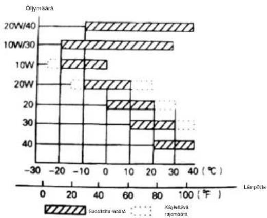
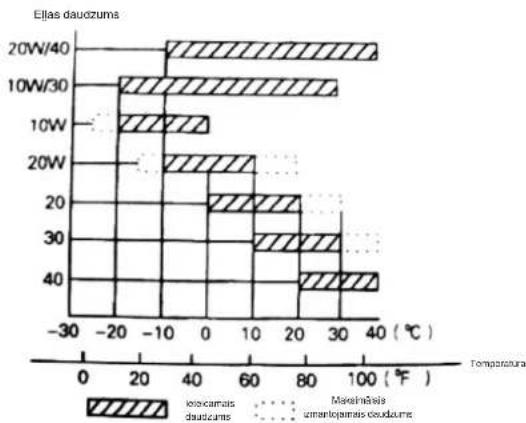
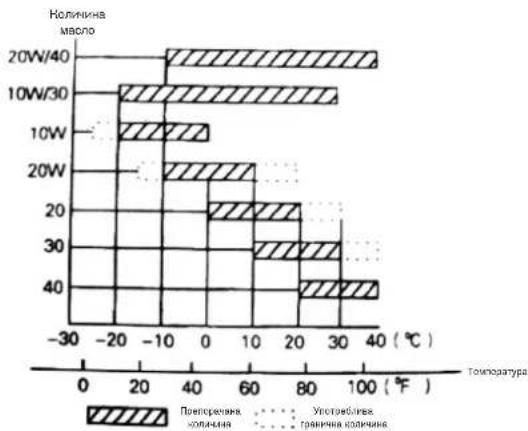
| Engine oil capacity | 0.6 L (SAE 15W-40 oil) |
| Spark plug electrode gap | 0.70 - 0.80 mm |
| Idle speed | 1800 ± 100 rpm |
| Maximum no-load speed | 3600 ± 50 rpm |
| Air filter maintenance | Every 50 hours (or 10 h in dusty conditions) |
| Engine oil change | First after 20 h, then every 50 h |
| Long-term storage | Drain gearbox lubricant, apply anti-corrosion oil |
Frequently Asked Questions - SRC 585 RG STIGA
User questions about SRC 585 RG STIGA
0 question about this device. Answer the ones you know or ask your own.
Ask a new question about this device
Download the instructions for your Rototiller in PDF format for free! Find your manual SRC 585 RG - STIGA and take your electronic device back in hand. On this page are published all the documents necessary for the use of your device. SRC 585 RG by STIGA.
USER MANUAL SRC 585 RG STIGA
natural_image
Icon of a person reading a book inside a circle (no text or symbols) | Motozappatrice condotta a piedi - MANUALE DI ISTRUZIONI |
 | ATTENZIONE: prima di usare la macchina, leggere attentamente il presente libretto.Мотокултиватор управляван от право положениеУПЪТВАНЕ ЗА УПОТРЕБА - ВНИМАНИЕ: преди да използвате машинатапрочетете внимателно настоящата книжка. |
 | Motokultivatoru kontrolisano pješacima - UPUTSTVO ZA UPOTREBUPAŽNJA: prilje nego što koristite ovu mašinu, pažljivo pročitajte priručnik s uputama. |
 | Ručně vedený motokultivátor - NÁVOD K POUŽITÍ |
 | UPOZORNĚNÍ: před použitím stroje si pozorně přečtěte tento návod k použití.Motorfræser betjent af gående personer - BRUGSANVISNING |
 | ADVARSEL: læs Instruktionsbogen omhyggeligt lgennem, før du tager denne maskine I brug.Handgeführte Motorhacke - GEBRAUCHSANWEISUNG |
 | ACHTUNG: vor Inbetrlebnahme des geräts die gebrauchsanleitung aufmerksam lesen.Σκαπτικό βενζίνης πεζού χειριστή - ΟΔΗΓΙΕΣ ΧΡΗΣΠΣ |
 | ПРОΣΟΧΗ: πριν χρησιμοποιησετε το μηχανημα, διαβαστε προσεκτικα το παρον εγχειριδιο.Tiller - OPERATOR’S MANUAL |
 | WARNING: read thoroughly the Instruction booklet before using the machine. |
 | ATENCIÓN: antes de utilizar la máquina, leer atentamente el presente manual.Kõndiva juhiga mullafrees - KASUTUSJUHEND |
 | TÄHELEPANU: enne masina kasutamist lugeda tähelepanelikult antud kasutusjuhendit.Kävellen ohjattava puutarhajyrsin - KÄYTTÖOHJEET |
 | VAROITUS: lue käyttöopas huolellisesti ennen koneen käyttöä.Motobineuse à conducteur à pied - MANUEL D’UTILISATION |
 | ATTENTION: lire attentivement le manuel avant d’utiliser cette machine.Ručno upravljana motorna kopačica - PRIRUČNIK ZA UPORABU |
 | POZOR: prije uporabe stroja, pažljivo pročitajte ovaj priručnik.Gyalogvezetésű kultivátor - HASZNÁLATI UTASÍTÁS |
 | FIGYELEM! a gép használata előtt olvassa el figyelmesen a jelen kézikönyvet.Pėsčio operatoriaus valdomas variklinis kultivatoriusNAUDOJIMO INSTRUKCIJOS - DĖMESIO: prieš naudojant įrenginį, atidžiał perskaityti šįnaudotojo vadovą. |
 | Kājniekvadāms motorkaplis - LIETOŠANAS INSTRUKCIJA |
 | UZMANĪBU: plirms aparāta lietošanal rūpīgl lzlaslet doto Instrukciju.Моторен плуг - УПАТСТВА ЗА УПОТРЕБА |
 | ВНИМАНИЕ: прочитајте го внимателно ова упатство пред да ја користите машината.Lopend bediende motorhakfrees - GEBRUIKERSHANDLEIDING |
 | LET OP: vooraleer de machine te gebruiken, dient men deze handleiding aandachtig te lezen.Motordrevet håndført jordfres - INSTRUKSJONSBOK |
 | ADVARSEL: les denne bruksanvisningen noye før du bruker maskinen.Glebogryzarka prowadzona przez operatora pieszegoINSTRUKCJE OBSŁUGI - OSTRZEŽENIE: przed użyciem maszyny, należy uważnie przeczytaćniniejszą instrukcję. |
 | Motoenxada para operador apeado - MANUAL DE INSTRUÇÕES |
 | ATENÇÃO: antes de usar a máquina, lela atentamente o presente manual.Motosapă cu conducător pedestru - MANUAL DE INSTRUCTIUNI |
 | ATENTIE: inainte de a utiliza mașina, citiți cu atenție manualul de față.Mотокультиватор с пешеходным управлениемРУКОВОДСТВО ПО ЭКСПЛУАТАЦИИ - ВНИМАНИЕ: прежде чем пользоватьсяоборудованием, внимательно прочтите это руководство по эксплуатации. |
 | Ručne vedená kultivátor - NÁVOD NA POUŽITIE |
 | UPOZORNENIE: pred použitím stroja si pozorne prečiftajte tento návod.Motorni prekopalnik za stoječega delavca - PRIROČNIK ZA UPORABO |
 | POZOR: preden uporabite stroj, pazljivo preberite priročnik z navodiii.Motokultivator na guranje - PRIRUČNIK SA UPUTSTVIMA |
 | PAŽNJA: pre korišćenja mašine pažljivo pročitatl ovaj priručnik.Förarledd jordfräs - BRUKSANVISNING |
 | WARNING: läs igenom hela detta hätte innan du använder maskinen.Ayak kumandalı motorlu çapa makinesi - KULLANIM KILAVUZUDÍKKAT: makineyi kullanmadan önce talimatlar içeren kilavuzu dikkatle okuyun. |
IT - TRADUZIONE DELLE ISTRUZIONI ORIGINALI
INDICE
1. NORME DI SICUREZZA 2


ATTENZIONE!
natural_image
Close-up of a hand adjusting a mechanical component with visible wiring and a circular detail (no text or symbols)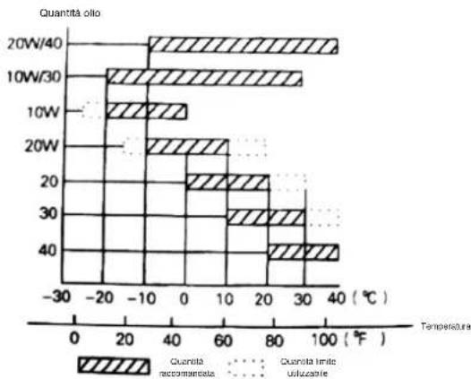
bar
| Temperature (°C) | Quantity oilo (°C) - Lactose | Quantity oilo (°C) - Unaccommodato | Quantity oilo (°C) - Uclustane | |---|---|---|---| | 20W/40 | 38 | -15 | - | | 10W/30 | 32 | -18 | - | | 10W | 10 | -5 | 0 | | 20W | 12 | -12 | 0 | | 20 | 60 | 20 | 0 | | 30 | 75 | 25 | 0 | | 40 | 35 | 35 | 0 |Figura 2 Tabella 1
natural_image
Close-up of a hand adjusting a mechanical component with a circular housing and bolts (no visible text or symbols)Figura 4
natural_image
Close-up of a mechanical clamp or bracket assembly with metal tubing and a curved handle (no text or symbols visible)
natural_image
Close-up of a mechanical agricultural machine with metal blades and mounting bracket (no visible text or symbols)Figura 5 Figura 6
natural_image
Mechanical lever handle and grip assembly (no text or symbols visible)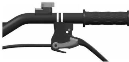
natural_image
Close-up of a black bicycle brake lever with handle and grip (no text or symbols visible)Figura 7 Figura 8
natural_image
Close-up of a mechanical belt drive system with pulleys and gears (no visible text or symbols)natural_image
Close-up of a mechanical assembly with visible gears and springs (no text or symbols)natural_image
3D rendered image of a black automotive brush tool with handle and lever (no text or symbols visible)
natural_image
Close-up of a black automotive brake lever handle and grip (no text or symbols visible)Figura 14 Figura 15
natural_image
Close-up of a mechanical vehicle's wheel and suspension components (no visible text or symbols)Figura 15 Figura 16
natural_image
Close-up of a mechanical engine component with visible blades and housing (no text or symbols)5. AVVIAMENTO
5.1. COME AVVIARE LA MACCHINA

Attenzione!
5.2. COME FERMARE IL MOTORE
natural_image
Line drawing of hands operating a mechanical device with a knob (no text or symbols)

Attenzione!

ВНИМАНИЕ!
natural_image
Close-up of a hand adjusting a mechanical component with a circular tool (no visible text or symbols)Фигура 2 Таблица 1

bar
| Temperature (°C) | Preoperatively MpaO | Oversaturated Ophthalate MpaO | |---|---|---| | 20W/40 | 38 | -15 | | 10W/30 | 30 | -10 | | 10W | 10 | -5 | | 20W | 10 | -5 | | 20 | 20 | 10 | | 30 | 25 | 15 | | 40 | 35 | 25 | The chart displays 'Temperature (°C)' on the x-axis, with 'Preoperatively MpaO' and 'Ophthalate MpaO' as legend categories. The bars are shaded with diagonal hatching for each category. The y-axis is labeled 'Temperature (°C)'.natural_image
Close-up of a hand adjusting a mechanical component with a circular housing and bolts (no visible text or symbols)Фигура 4
natural_image
Close-up of a mechanical clamp or bracket with metal wire being inserted (no text or symbols visible)Фигура 5 Фигура 6
natural_image
Close-up of a mechanical assembly with metal components and wiring (no visible text or symbols)natural_image
Mechanical lever handle and grip assembly (no text or symbols visible)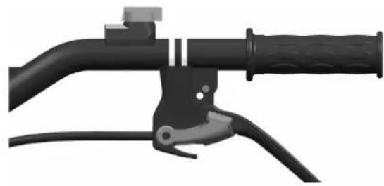
natural_image
Mechanical lever handle and grip assembly (no text or symbols visible)Фигура 7 Фигура 8
natural_image
Mechanical assembly diagram showing a belt drive system with pulleys and gears (no text or symbols)natural_image
Mechanical assembly diagram showing motor and gear components with no visible text or symbolsnatural_image
3D rendered image of a black automotive lever handle and grip assembly (no text or symbols visible)
natural_image
Close-up of a black automotive lever handle and cable assembly (no text or symbols visible)Фигура 14 Фигура 15
natural_image
Close-up of a mechanical vehicle's wheel assembly with visible suspension components (no text or symbols)Фигура 15 Фигура 16

natural_image
Close-up of a mechanical assembly with a wheel and pump component (no visible text or symbols)5. СТАРТИРАНЕ
natural_image
Line drawing of a hand using a tool to adjust or install a mechanical component (no text or symbols visible)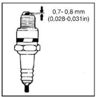

Внимание!


PAŽNJA!
natural_image
Close-up of a hand adjusting a mechanical component with a circular tool (no visible text or symbols)Slika 2 Tabela 1
bar
| Temperature (°C) | Preporučenis količina | Grančne količina koja se može količini | |---|---|---| | 20W/40 | -10 | 35 | | 10W/30 | -15 | 30 | | 10W | 0 | 5 | | 20W | 10 | 0 | | 20 | 20 | 0 | | 30 | 20 | 0 | | 40 | 35 | 0 |natural_image
Close-up of a hand adjusting a mechanical component with a circular housing and bolted joints (no visible text or symbols)Slika 4
- Kontrola filtra za zrak

Pažnja!
natural_image
Close-up of a mechanical clamp or bracket assembly with metal tubing and a curved handle (no text or symbols visible)
natural_image
Close-up of a mechanical agricultural machine component with no visible text or symbolsSlika 5 Slika 6
natural_image
Mechanical lever handle assembly with black and gray components (no text or symbols visible)
natural_image
Mechanical lever handle and grip assembly (no text or symbols visible)Slika 7 Slika 8
- Kad rukovatelj pusti polugu kvačila, kvačilo je isključeno, a struja motora se ne prenosi na motokultivator i noževi se prestaju okretati (vidi Sl. 8).
Napomena: Prije nego što podesite visinu ručica pluga, postavite mašinu vodoravno na ravni teren da slučajno ne padne.
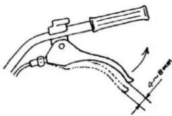
- Prije svega provjerite je li kabel kvačila zategnut. Obično kabel treba imati zazor od 4-8 mm; ako nije tako, popustite maticu za fiksiranje i podesite kabel. Kada završite podešavanje, pritegnite maticu za fiksiranje (vidi SI. 9).
- Ako je potrebno, rukovatelj može pokrenuti motor da bi provjerio da li se kvačilo pravilno aktivira i deaktivira.
Slika 9
4. Podešavanje zategnutosti kaiša:
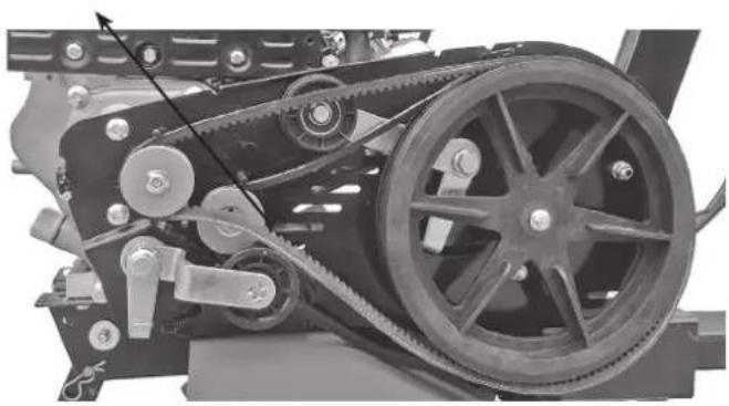
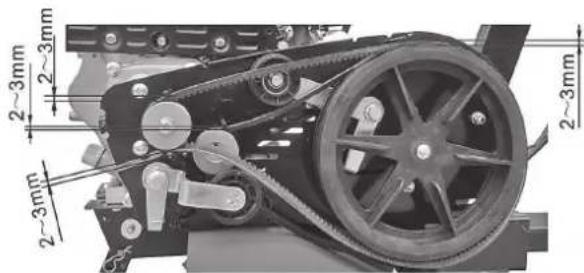
- Ako zategnutost kaiša nije u granicama vrijednosti nazivnog zatezanja, trebate podesiti kaiš. Popustite 4 matice motora (vidi SI. 10 i 11).
- Kada odvrnete četiri matice na motoru, ako je kaiš jako labav, gurnite motor naprijed, a ako je kaiš suviše zategnut, gurajte motor unatrag sve dok se kaiš normalno ne zategne. Potom pritegnite matice na motoru i na spojnom tanjiru (vidi SI. 12).
natural_image
Mechanical assembly showing a belt drive system with pulleys and gears (no visible text or symbols)Slika 10 Matice motora

natural_image
Close-up mechanical assembly showing internal components and wiring (no visible text or symbols)Slika 11 Matice motora
5. Podešavanje kabela gasa:
- Normalna brzina: 1800±100 okretaja/min; prevelika brzina: 3000±50 okretaja/min. Brzina se može regulirati pomoću brojača okretaja.
- Način kontrole i podešavanja brzine. Podešavanje kabela gasa
Slika 12 Slika 13
Poluga gasa
- Okrenite polugu gasa na ručicu za plugove do maksimuma bez opterećenja i provjerite pokazuje li brojač okretaja brzinu između 3600±50 okretaja/min. Potom okrenite polugu do minima i provjerite je li na brojaču prikazana brzina između 1800±100 okretaja/min.
- Ako brzina koju pokaže brojač okretaja nije u rasponu navedenih vrijednosti, trebate podesiti motor.
natural_image
Two black automotive lever handle assemblies shown from front and side views (no text or symbols visible)Slika 14 Slika 15
- Kad rukovatelj pusti polugu kvačila, kvačilo je isključeno, a struja motora se ne prenosi na motokultivator i noževi se prestaju okretati (vidi SI. 15).
Napomena: Kada koristite polugu invertora pogona, radite u sigurnosnim uslovima. Neodgovarajuće podešavanje kabela kvačila ugrožava normalni rad mašine.
7. Podešavanje pomoćnog točka:
natural_image
Close-up of a mechanical vehicle's wheel and suspension components (no visible text or symbols)Slika 15 Slika 16

natural_image
Close-up of a mechanical component with a wheel and attached fan (no visible text or symbols)5. STARTANJE
5.1. POSTUPAK STARTANJA MAŠINE

Pažnja!
Prije nego što pokrenete motor, poluga mjenjača mora biti u leru. Trebate pustiti polugu kvačila.
- Postavite polugu zraka na CLOSE (zatvoreno).
- Okrenite lagano polugu gasa na najveću brzinu.
- Postavite prekidač motora na ON (otvoreno).
Lagano povucite kabel elektropokretača sve dok se on ne počne opirati, zatim ga povucite prema vani brzo i snažno.
Nemojte odjednom pustiti polugu jer bi ona mogla odskočiti unatrag i pogoditi i oštetiti motor. Za puštanje poluge, pustiti istu da polako klizi duž sajle za startanje.

- Kad se motor zagrije, lagano gurnite polugu zraka prema OPEN (otvoriti).

- Koristite polugu gasa (ili polugu leptirastog ventila) da podesite brzinu motora do potrebne vrijednosti.

5.2. POSTUPAK ZAUSTAVLJANJA MOTORA
- U slučaju nužde, motor se može zaustaviti izravno kad se prekidač motora postavi na OFF.
-
U normalnim uslovima, postupak gašenja motora je sljedeći:
-
Gurnite polugu gasa prema minimimu.
- Okrenite prekidač motora na OFF.
6. ODRŽAVANJE BENZINSKOG MOTORA

Pažnja!
• Zaustavite motor prije održavanja istog.
- Da ne bi došlo do slučajnog startanja motora, postavite prekidač motora na OFF (zaustavljeno) i otkačite liniju za spajanje svjećicu za paljenje.
- Kontrolu i održavanje motora može izvršiti samo ovlašteni distributer, osim ako rukovatelj ne posjeduje alat i materijal potrebni za kontrolu i održavanje i ako je u stanju popraviti motor i izvršiti održavanje motora.
Napomena: Ako želite održati dobar učinak motora, isti morate redovito kontrolirati i podešavati. Redovito održavanje garantira dug radni vijek motokultivatora. U donjoj tablici opisani su potrebni vremenski intervali održavanja i dijelovi koje treba održavati.
| Komponenta | Svakodnevna upotreba | Nakon prvog mjeseca/ nakon 20 sati | Jednom u sezoni/ svakih 50 sati | Jednom u 6 mjeseci/ svakih 100 sati | Jednom godišnje/ svakih 300 sati | |
| Motorno ulje | Kontrola nivoa ulja | ● | ||||
| Zamjena ulja ● ● | ||||||
| Mazivo u mjenjačkoj kutiji (nalazi se kod nekih modela) | Kontrola ulja | ● | ||||
| Dodavanje ulja | ● | ● | ||||
| Filtar zraka | Kontrola | ● | ||||
| Čišćenje | ● | |||||
| Svjećica za paljenje | Kontrola i čišćenje | ● | ||||
| Štitnik od iskri (opcija) Čišćenje ● | ||||||
| Spremnik i filtar za gorivo | Čišćenje | ● | ||||
| Ventil za zrak | Kontrola/ podešavanje | ● | ||||
| Linija goriva Kontrola Jednom u 2 godine (ako je potrebno, zamijenite) ● | ||||||
Napomena:
- Ako mašinu koristite u prašnjavoj sredini, održavanje trebate češće vršiti.
- Rukovatelj ne može skinuti motor ako ne posjeduje odgovarajući alat i znanje potrebno da izvrši popravku.
6.1. ZAMJENA MOTORNOG ULJA
natural_image
Line drawing of hands operating a mechanical device with a knob (no text or symbols)

Pažnja!


UPOZORNĚNÍ!
natural_image
Close-up of a hand adjusting a mechanical component with a circular tool (no visible text or symbols)Obrázek 2 Tabulka 1
bar
| Wind Speed | Mnozati Oleje (°C) | Doporubene minozaté (°C) | Doublehne maxni minozaté (°C) | | :--- | :--- | :--- | :--- | | 20W/40 | -10 | 35 | 38 | | 10W/30 | -15 | 30 | 32 | | 10W | 0 | 0 | 0 | | 20W | 10 | 0 | 0 | | 20 | 20 | 15 | 25 | | 30 | 30 | 25 | 35 | | 40 | 40 | 35 | 45 | Tepotanatural_image
Close-up of a hand adjusting a mechanical component with a circular housing and mounting bracket (no visible text or symbols)Obrázek 4
natural_image
Close-up of a mechanical clamp or bracket with metal wire being inserted (no text or symbols visible)
natural_image
Close-up of a mechanical agricultural machine component with no visible text or symbolsObrázek 5 Obrázek 6
natural_image
Close-up of a black bicycle brake lever handle and grip (no text or symbols visible)
natural_image
Mechanical lever handle and grip assembly (no text or symbols visible)Obrázek 7 Obrázek 8
natural_image
Mechanical assembly showing a belt drive system with pulleys and gears (no visible text or symbols)natural_image
Close-up mechanical assembly showing internal components and wiring (no visible text or symbols)natural_image
3D rendered image of a black automotive lever handle and grip (no text or symbols visible)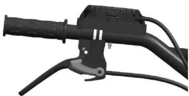
natural_image
Close-up of a black automotive brake lever handle and grip (no text or symbols visible)natural_image
Close-up of a mechanical vehicle's wheel assembly and suspension mechanism (no visible text or symbols)natural_image
Close-up of a mechanical engine component with visible blades and housing (no text or symbols)5. STARTOVÁNÍ
5.1. JAK NASTARTOVAT STROJ

Upozornění!
5.2. JAK ZASTAVIT MOTOR

6. ÚDRŽBA BENZINOVÉHO MOTORU

Upozornění!
natural_image
Line drawing of a hand using a tool to adjust or install a mechanical component (no text or symbols visible)

Upozornění!

ADVARSEL!
natural_image
Close-up of a hand adjusting a mechanical component with a circular tool (no visible text or symbols)Figur 2 Tabel 1
bar
Ollemaengde | Oil Mix | Anoctalei mangle (°C) | Mindst Brugbar mangle (°C) | |---|---|---| | 20W/40 | -15 | 38 | | 10W/30 | -15 | 30 | | 10W | -5 | 0 | | 20W | -10 | 10 | | 20 | 20 | 80 | | 30 | 20 | 60 | | 40 | 35 | 100 |natural_image
Close-up of a hand adjusting a mechanical component with a circular housing and mounting bracket (no visible text or symbols)Figur 4
natural_image
Close-up of a mechanical clamp or bracket with metal wire and clamping tool (no text or symbols visible)
natural_image
Close-up of a mechanical agricultural machine component with no visible text or symbolsFigur 5 Figur 6
natural_image
Mechanical lever handle assembly with black and gray components (no text or symbols visible)
natural_image
Mechanical lever handle and grip assembly (no text or symbols visible)Figur 7 Figur 8
natural_image
Mechanical assembly showing a belt drive system with pulleys and gears (no visible text or symbols)Figur 10 Møtrikker motor

natural_image
Close-up mechanical assembly showing internal components and wiring (no visible text or symbols)Figur 11 Møtrikker motor
natural_image
Two black automotive lever handle assemblies shown from front and side views (no text or symbols visible)Figur 14 Figur 15
natural_image
Close-up of a mechanical vehicle's wheel and suspension components (no visible text or symbols)Figur 15 Figur 16

natural_image
Close-up of a mechanical assembly with a wheel and attached component (no visible text or symbols)5. START
5.1. SÅDAN STARTES MASKINEN

Advarsel!
natural_image
Line drawing of hands using a tool to adjust or install a mechanical component (no text or symbols visible)

Advarsel!


VORSICHT!
natural_image
Close-up of a hand adjusting a mechanical component with a circular tool (no visible text or symbols)natural_image
Close-up of a hand adjusting a mechanical component with a black housing and bolted joints (no visible text or symbols)Abbildung 4
natural_image
Close-up of a mechanical clamp or bracket with metal wire and cable (no text or symbols visible)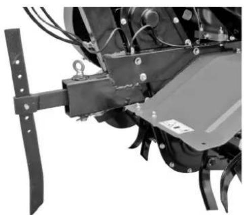
natural_image
Close-up of a mechanical assembly with metal components and wiring (no visible text or symbols)natural_image
Mechanical lever handle assembly with black and gray components (no text or symbols visible)
natural_image
Mechanical lever handle and grip assembly (no text or symbols visible)natural_image
Mechanical assembly diagram showing a belt drive system with pulleys and gears (no text or symbols)natural_image
Mechanical assembly diagram showing motor components and wiring (no text or labels visible)natural_image
3D rendered image of a black automotive brush tool with attached cable and handle (no text or symbols visible)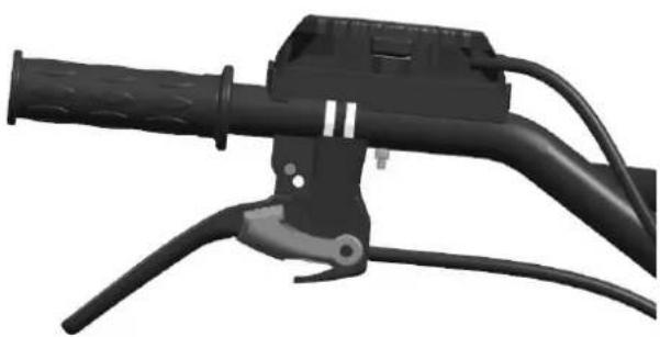
natural_image
Close-up of a black automotive lever handle and cable (no text or symbols visible)natural_image
Close-up of a mechanical component with visible wheels and mounting brackets (no text or symbols)natural_image
Close-up of a mechanical engine component with visible blades and hub (no text or symbols)5. ANLASSEN
5.1. ANLASSEN DER MASCHINE

Vorsicht!
natural_image
Line drawing of a hand using a tool to adjust or install a mechanical component (no text or symbols visible)

Vorsicht!
ΠΡΟΣΟΧΗ!
natural_image
Close-up of a hand adjusting a mechanical component with a circular tool (no visible text or symbols)Εικόνα 2 Πίνακας 1
bar
| Wind Speed | Solar Temperature (°C) | Peacarous Temperature (°C) | |---|---|---| | 20W/40 | -15 | 38 | | 10W/30 | -15 | 30 | | 10W | -5 | 0 | | 20W | -15 | 10 | | 20 | 20 | 80 | | 30 | 20 | 30 | | 40 | 20 | 35 | | 40 | 40 | 40 |natural_image
Close-up of a hand adjusting a mechanical component with a circular housing and bolted joints (no visible text or symbols)Eikóva 4
natural_image
Close-up of a mechanical clamp or bracket assembly with metal tubing and a curved handle (no text or symbols visible)
natural_image
Close-up of a mechanical agricultural machine component with no visible text or symbolsΕικόνα 5 Εικόνα 6
natural_image
Mechanical lever handle and grip assembly (no text or symbols visible)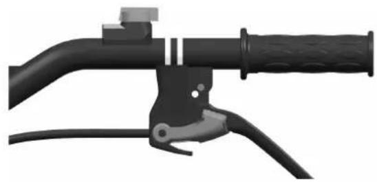
natural_image
Mechanical lever handle and grip assembly (no text or symbols visible)Εικόνα 7 Εικόνα 8
Eikóva 9
natural_image
Mechanical assembly diagram showing a belt drive system with pulleys and gears (no text or symbols)natural_image
Mechanical assembly diagram showing motor and gear components with no visible text or symbolsnatural_image
3D rendered image of a black automotive lever handle and grip assembly (no text or symbols visible)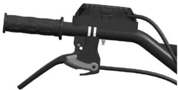
natural_image
Close-up of a black automotive brake lever handle and grip (no text or symbols visible)Εικόνα 14 Εικόνα 15
natural_image
Close-up of a mechanical device with wheels and attached brackets (no visible text or symbols)Εικόνα 15 Εικόνα 16

natural_image
Close-up of a mechanical component with a wheel and fan assembly (no visible text or symbols)5. EKKINHΣH
natural_image
Line drawing of hands using a tool to adjust or install a mechanical component (no text or symbols visible)

Προσοχή!
Please pay special attention to the following information:
Please read carefully this operation and maintenance manual before operation and strictly comply with the manual while operating. If you operate in compliance with the manual, the tiller designed by our company can work safely and reliably without damage to equipment and personal injury. Should you not operate in compliance with the manual, there may occur severe damage or injury to your equipment or your body.
1. SAFETY WARNINGS
1.1. TRAINING
a) Carefully read the operation manual. Get fully familiar with the correct method of operation of this machine and its mechanisms. Understand how to stop it and how to quickly disengage the operation mechanism.
b) No child is allowed to use the machine! No adult is allowed to use the machine before carefully reading the manual!
c) Ensure no other persons or things with potential safety risk, especially children and pets, are inside the working area!
1.2. PREPARATION
a) Thoroughly check the area for the machine to work in, and remove all sundries.
b) Before starting the engine, put shift gear in neutral position!
c) Don't operate the machine without the proper clothing. If the working area has a slippery ground, wear a pair of anti-skid shoes to improve your standing stability.
d) Take care when treating fuel, which is inflammable! Pay attention to the following rules:
1) Use an appropriate container to hold the fuel.
2) When the engine is running or is hot, never try to add fuel into it!
3) Take extra care when fueling the engine outdoors; never try to fuel the engine indoors!
4) Before starting, tighten the fuel tank cap and wipe off any fuel spilled out!
e) Never try to make any adjustment when the engine is running!
f) For any operation or work on the machine, for example, preparation and maintenance of the machine, wearing a pair of safety glasses is necessary.
1.3. OPERATION
a) When starting the engine, the shift lever shall stay in the neutral position. The operator's hands and feet are not allowed to approach revolving parts or to be under such parts.
b) When operating the machine on (or while crossing) a cobbled road, sidewalk, or highway, stay alert to the traffic conditions to notice any potential traffic risk! Never use the machine to carry any passenger!
c) If the machine bumps against any foreign thing, please shut off the engine immediately, and thoroughly check whether the tiller is damaged; if so, repair it before restarting and operating it.
d) Always pay attention to the surrounding conditions to avoid slipping down, or dropping.
e) If the machine shows any abnormal vibration, shut off the engine without any delay! Check to find the reason, it's important because abnormal vibration normally is harbinger of fault.
f) Before leaving the operating position to repair, adjust, check or remove of things jammed between blades, always remember to shut off the engine first!
g) If the machine is to be left uncared by the operator, all necessary preventive measures, such as disengaging power output shaft, lowering of accessory devices, shift to neutral position of gear shift lever, and shutting off the engine shall be taken first!
h) Before cleaning, repair or checking the machine, the operator must shut off the engine and ensure all moving parts are in a stationary state!
i) Engine's emission is hazardous, so never try to run it indoors!
j) Never operate the tiller without proper protection equipment, guard or other protection devices in place!
k) When the machine is running, always keep it away from children and pets!
I) Never overload the machine with a big tilling depth and a high speed!
m) The machine is not allowed to run at a high speed on a slippery road. Watch back to take care when driving backward!
n) Never allow any looker-on to approach a running machine!
o) Only the accessory devices and equipment (like the counter weight) allowed by the manufacturer of the tiller may be used
p) Never try to operate the tiller when the view is limited or lighting conditions are poor!
q) Take care when tilling a hard field, because the blades may hook into the ground, hence pushing the tiller forward. If such a result does occur, just let free the handle and don't try to control the machine!
r) Never operate the tiller on an abrupt slope!
s) Take care not to let the machine turn over when it is ascending or descending a slope!
1.4. REPAIR, MAINTENANCE AND STORAGE
a) Keep the machine, accessory devices and equipment, including the battery, in a safe working condition. Whenever possible, detach the battery before storage to prevent freezing, and charge it to some extent when it is necessary to do so.
b) Check whether bolts under shear stress, mounting bolts of engine and other bolts are tightened properly at a fixed interval, so as to ensure the machine can work safely.
c) The machine shall be stored indoors and away from flames, and cool the engine before storing it.
d) If the tiller is to be stored for a long time, the manual shall always be kept as an important material.
e) Don't repair the machine at will unless you have the proper tools and the manual to instruct disassembling, assembling and repairing of the machine.
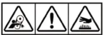
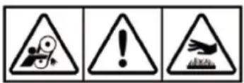
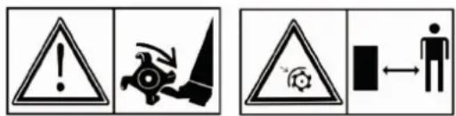
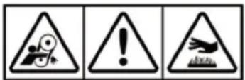
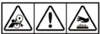
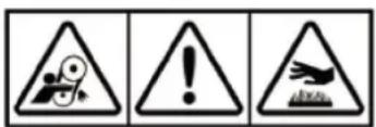
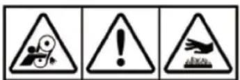
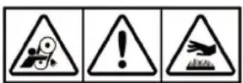
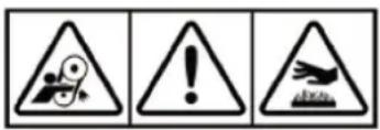
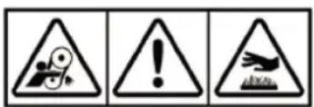
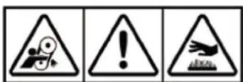
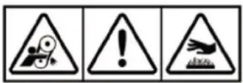
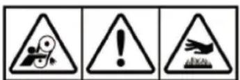
2. SAFETY SYMBOLS
The following symbols are to remind you that if you don't pay attention, you might be severely injured. Please carefully read the symbols in the manual and notices about safety.
If these symbols peel off or are illegible, please contact the distributor to replace such symbols.
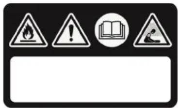


WARNING!
Read the instructions before operating the machine
DANGER! Engines emit carbon monoxide.
DANGER! Fuel is flammable and explosive.
WARNING
DANGER! Keep away from hot surfaces.
DANGER! Keep hands and feet away from rotating parts.
DANGER! Keep the work area free of people, children and animals.
DANGER! Turning rotor Always keep away from tilling blades
3. BRIEF INTRODUCTION OF TILLER
3.1. MAJOR TECHNICAL PARAMETERS
| Power 3.5 kW | |
| Engine rotations 3300 min | -1 |
| Starting Recoil start | |
| Net weight/ gross weight 62.5 kg | |
| Tilling width 82cm | |
| Tilling depth ≥10 cm | |
| Working speed 0.1~0.3 m/s | |
| Transmission With belt and chain wheel | |
| Rotate speed 120 r/min | |
| Measured sound power level | 95.21 dB (A) |
| Uncertainty | 2.0 dB (A) |
| Guaranteed sound power level | 97 dB (A) |
| Sound pressure level | 75.21 dB (A) |
| Uncertainty | 1.46 dB (A) |
| Vibrations transmitted to handlebar | < 2.5 m/s ^2 |
| Uncertainty | 2.0 m/s ^2 |
3.2. NAMES OF MAJOR PARTS AND COMPONENTS OF TILLER
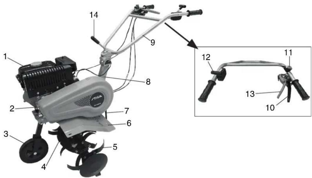
Figure 1
- Gasoline engine
- Reduction box
- Damping lever
- Clutch handle, forward
-
Clutch handle, reverse
-
Belt guard
- Tilling blade
- Bracket
- Extinguishing switch
-
Lifting part
-
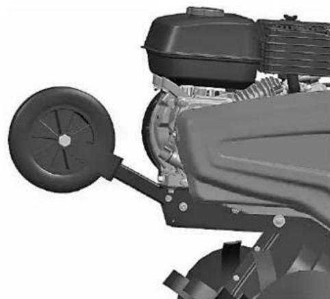
Front wheel assembly
- Fender
- Handle pipe assembly
- Accelerator valve regulator
Before each tiller leaves the factory, it has gone through shakedown test, but the user still should check all mechanisms of the machine and adjust them before actually using it, so as to let it work better.
4.1. ROUTINE CHECK
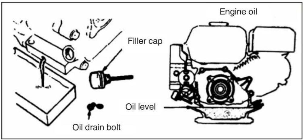
1. Check engine oil

Warning!
The engine shall be filled with 0.6L of engine oil. If the level of engine oil is lower than the normal one when the user is using the engine, the engine will be severely damaged!

Warning!
Please use clean and high-quality engine oil for four-stroke engines. Use of dirty oil or any other type of engine oil will shorten the engine's service life.
- Put the engine in a horizontal position.
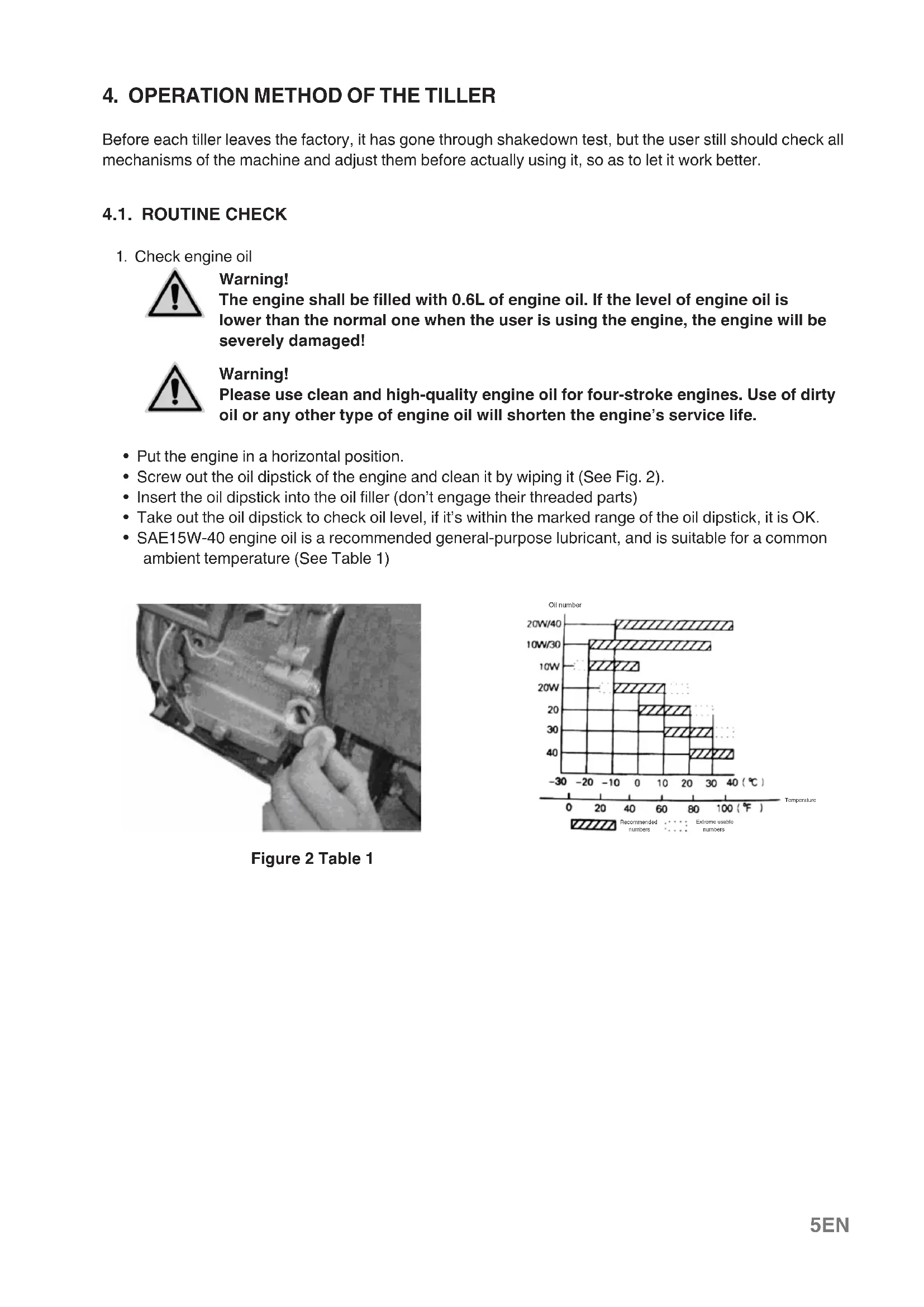
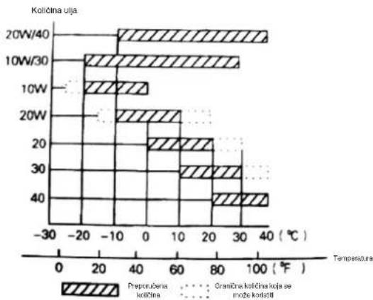
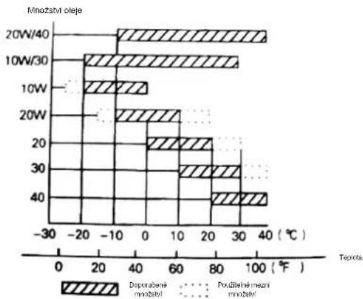
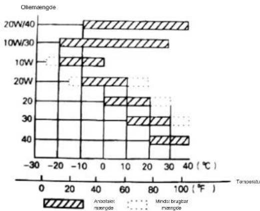
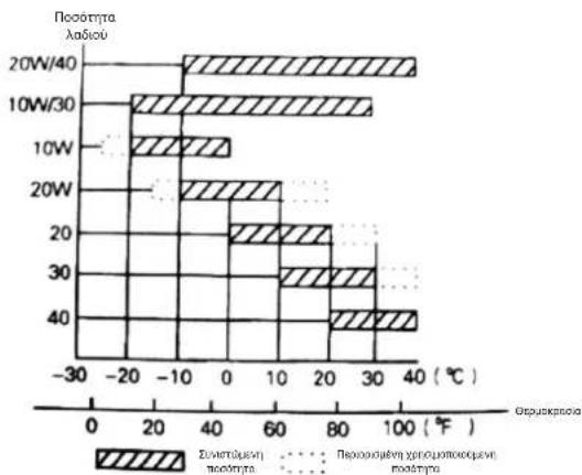
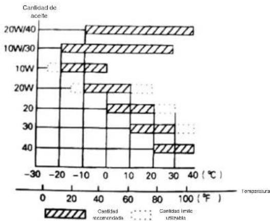
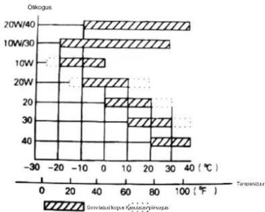
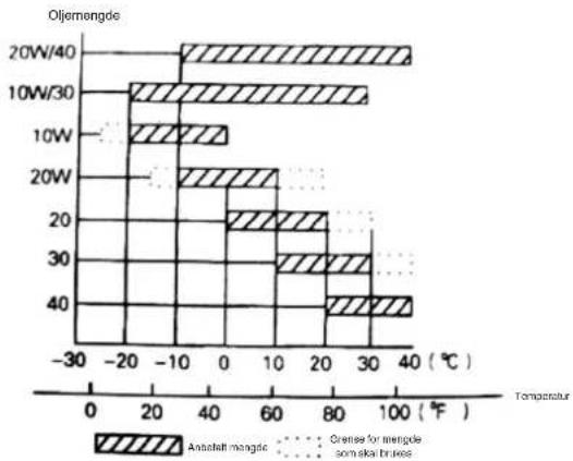
- Screw out the oil dipstick of the engine and clean it by wiping it (See Fig. 2).
- Insert the oil dipstick into the oil filler (don't engage their threaded parts)
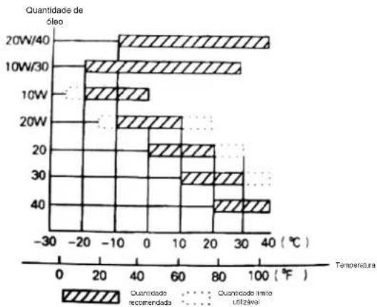
Take out the oil dipstick to check oil level, if it's within the marked range of the oil dipstick, it is OK. - SAE15W-40 engine oil is a recommended general-purpose lubricant, and is suitable for a common ambient temperature (See Table 1)
natural_image
Close-up of a hand adjusting a mechanical component with a circular tool (no visible text or symbols)Figure 2 Table 1

bar
| Oil number | Temperature (°C) | Recommendation Number | Recommendation Numbers | |---|---|---|---| | 20W/40 | 0 | 38 | 38 | | 10W/30 | 0 | 30 | 30 | | 10W | 20 | -15 | -15 | | 20W | 20 | -15 | -15 | | 20 | 30 | 20 | 20 | | 30 | 30 | 20 | 20 | | 40 | 30 | 35 | 35 | The chart displays the recommended numbers and recommended numbers for each oil price at different temperatures. The x-axis represents temperature in degrees Celsius, and the y-axis represents the oil price. The legend distinguishes between 'Recommended numbers' (hatched bars) and 'Extremable numbers' (dotted lines).-
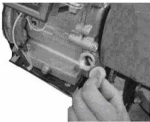
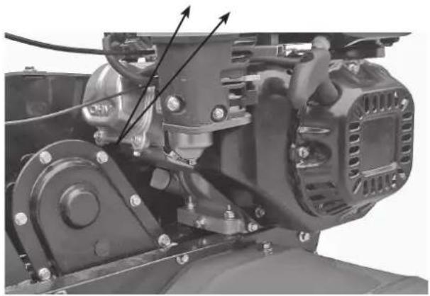
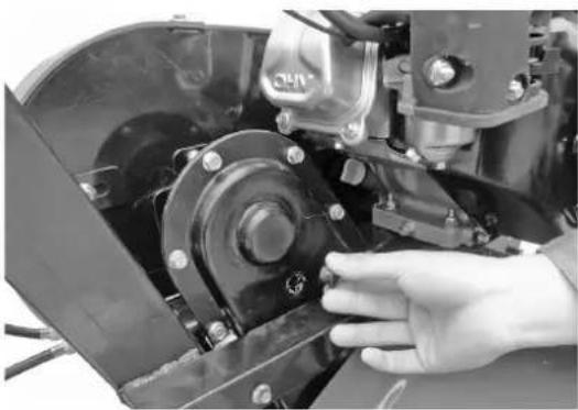
Check lubricant in reduction box
-
Put the tiller on a horizontal ground and screw out the plug (See Fig.4).
- Advise append appropriate lubricant to the reduction box every 50 hours.
- Recommended lubricant is Calcium base grease.

natural_image
Close-up of a hand adjusting a mechanical component with a black housing and bolted joints (no visible text or symbols)Figure 4
- Check air filter

Warning!
Never try to run the engine without the air filter, if so, the engine will be worn more quickly.
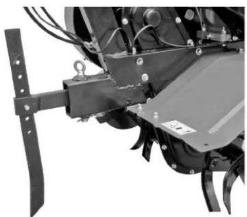
4.2. STATUS ADJUSTMENT OF THE TILLER
- Adjustment of handle frame
Note: Before adjusting height of handle frame, please put the machine on a flat horizontal ground to prevent it from accidental falling.
- Loosen the lifting handle and select the hole in an appropriate position, then adjust the handle's cross bar to as high as user's waist, then turn the lifting handle to tighten it (See Fig. 5).
- Adjustment of tilling depth:
- By adjusting height of damping lever, tilling depth can be adjusted. Specifically, adjusting the lever downward will increase tilling depth, and adjusting it upward will decrease tilling depth. (See Fig. 6).
natural_image
Close-up of a mechanical clamp or bracket with a metal wire inserted, no visible text or symbols
natural_image
Close-up of a mechanical agricultural machine component with no visible text or symbolsFigure 5 Figure 6
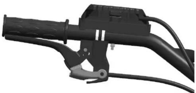
3. Adjustment and use of clutch:
Note: Before using the clutch, lower the engine speed.
- By "engage" and "disengage" of the clutch, the user can control output of engine's power.
- When the user holds tight the clutch lever, the clutch is engaged and transmits engine power to the tiller and tilling blades begin to rotate (See Fig. 7).
natural_image
Mechanical lever handle assembly with black and gray components (no text or symbols visible)
natural_image
Mechanical lever handle and grip assembly (no text or symbols visible)Figure 7 Figure 8
- When the user releases clutch lever, clutch will be disengaged, and the engine power can't be transmitted to the tiller, and tilling blades stop rotating (See Fig. 8).
Note: Before adjusting height of handle frame, please put the machine on a flat horizontal ground to prevent it from accidental falling.
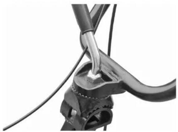
- First confirm tension of clutch cable. Normally the cable shall have a 4\~8mm degree of freedom, if not, please loosen the locking nut and adjust the cable, and tighten the locking nut after finishing adjustment (See Fig. 9).
- If necessary, the user may start the engine to check whether the clutch can engage and disengage properly.

Figure 9
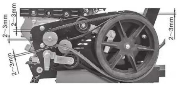
4. Adjustment of belt tension:
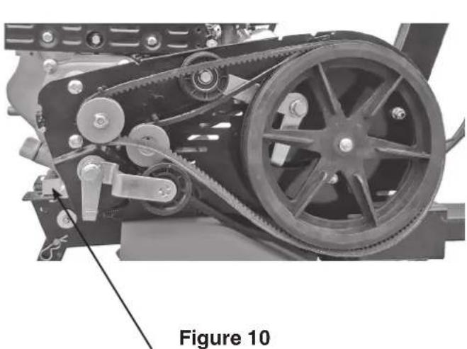
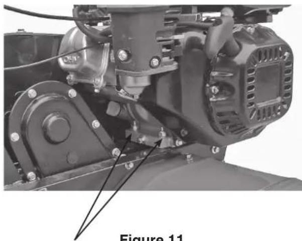
- If belt tension isn't in the normal tension range, it needs adjustment. Please loosen the engine's 4 mounting bolts (See Fig.10 10 and 11).
- After loosen the engine's 4 mounting bolts, then if belt is too loose, push the engine forward, and if belt is too tight, move backward the engine till belt tension falls in the normal range, finally tighten engine's mounting bolts and connection plate's mounting bolts (See Fig. 12).
natural_image
Mechanical assembly diagram showing a belt drive system with pulleys and gears (no text or symbols)\ Figure 10 Engine mounting bolt
natural_image
Mechanical assembly diagram showing motor components and wiring (no text or symbols)Figure 11 Engine mounting bolt
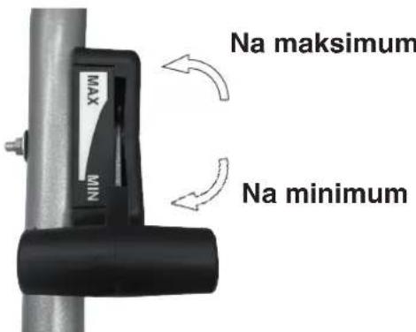
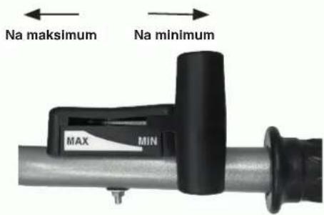
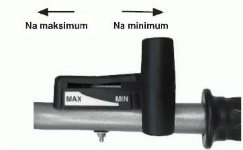
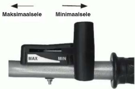
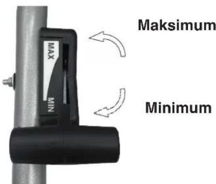
5. Adjustment of accelerator cable:
- Idling within normal speed range: 1800±100 Rpm; within high speed range 3300 Rpm, and it can be adjusted using a speed counter.
• Method of confirming speed and adjustment of it. Adjustment of accelerator cable
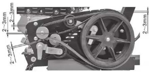
Figure 12 Figure 13
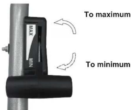
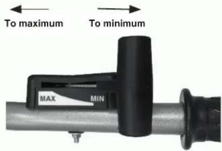
Accelerator valve regulator
- Turn the accelerator valve regulator on the handle frame to the maximum adjustable position without any load, and check if speed counter shows the speed is 3600 ± 50 , and then turn the accelerator valve regulator to the minimum adjustable position and check whether speed counter shows the speed is 1800 ± 100 .
- If the speed value displayed by the speed counter isn't within the said ranges, it is necessary to adjust the gasoline engine.
Steps to adjust the engine:
a) Observe whether connection points of the accelerator cable are loose or have broken off, if so, retighten them to their original places.
b) Turn accelerator valve regulator on the handle frame to the maximum adjustable position without load, and then adjust the speed adjusting bolt of the gasoline engine's accelerator operation mechanism to a proper position.
c) After long work, the user may adjust the fine-adjusting bolt of the accelerator cable to adjust the engine.
- Use the clutch of reverse gear:

Warning!
Before using the clutch of reverse gear, lower the engine speed.
- By "engage" and "disengage" of the clutch of reverse gear, the user can control output of engine's power.
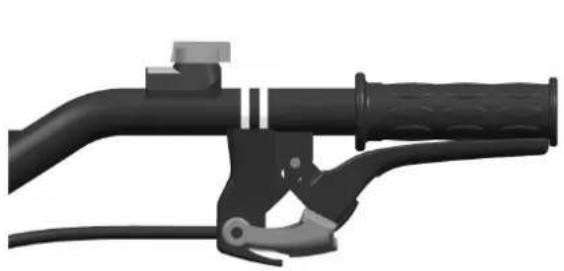
- When the user holds tight the clutch lever, the clutch is engaged and transmits engine power to the tiller and tilling blades begin to reverse rotate (See Fig. 14).
natural_image
3D rendered image of a black mechanical lever handle and grip assembly (no text or symbols visible)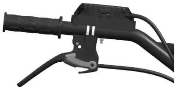
natural_image
Close-up of a black automotive lever handle and cable assembly (no text or symbols visible)Figure 14 Figure 15
- When the user releases clutch lever, clutch will be disengaged, and the engine power can't be transmitted to the tiller, and tilling blades stop rotating (See Fig. 15).
Note: When using the clutch of reverse gear, especial pay attention to safety. Sure, improper adjustment of clutch cable will affect normal use of the product.
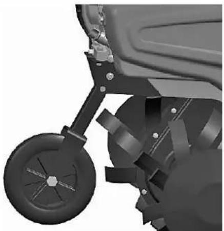
-
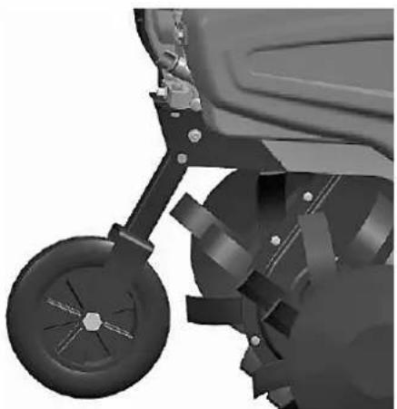
Adjustment of front wheel:
-
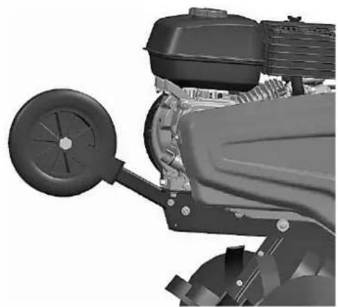
Adjust front wheel of tiller to the state shown in Fig. 15 when it is going to drive on the road.
- Adjust front wheel of tiller to the state shown in Fig. 16 when it is going to till the field.
natural_image
Close-up of a mechanical vehicle's wheel assembly (no visible text or symbols)Figure 15 Figure 16

natural_image
Close-up of a mechanical engine component with visible blades and housing (no text or symbols)5. STARTING
5.1. STEPS TO START IT

Warning!
Before starting the engine, gear shift lever must be put in the neutral position. Clutch lever shall be released.
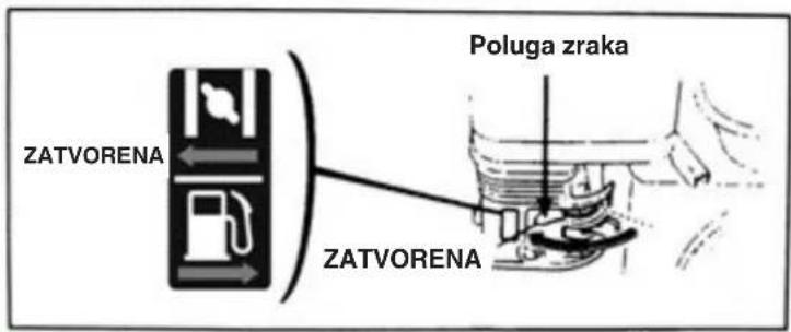
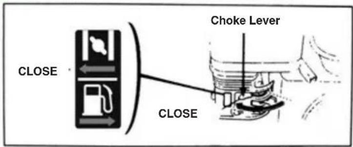
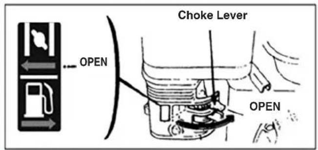
- Put the choke lever to the CLOSE position.
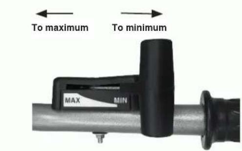
- Turn the accelerator valve regulator lever slightly to the direction for high speed
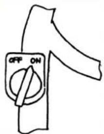
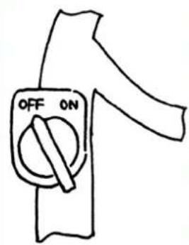
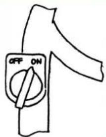
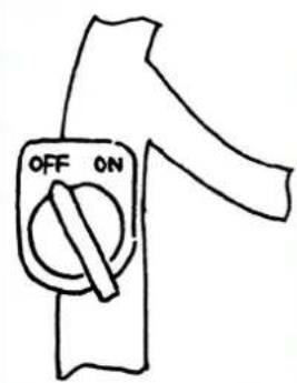
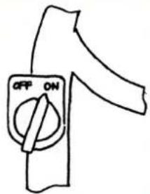
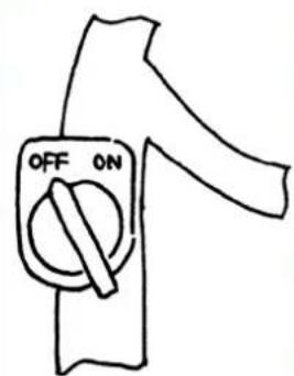
- Put the engine switch to ON (open) position.
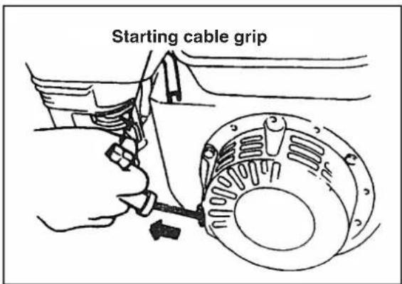
Slightly pull the starter cable until you feel a resistance, and then pull it out fast with a big force.
Never abruptly release the lever, which would let it bounce back to hit and damage the engine, so if you want to release, slowly let it back in the direction of the starter cable's resilience.
- After the engine has warmed up, slowly push the choke lever to OPEN position.
- Use the accelerator valve regulator (or throttle valve lever) to regulate the engine speed to the need level.

5.2. HOW TO STOP THE ENGINE
- Under an emergency, the engine can be stopped, which means the user can directly shift the engine switch to OFF position.
• Under a normal condition, the steps to stop the engine are as follows:
-
Push the accelerator valve regulator to the minimum position.
-
Turn the engine switch to OFF position.
6. MAINTENANCE OF GASOLINE ENGINE

Warning!
- Stop the engine before any maintenance.
- In order to prevent inadvertent starting of the engine, please put the engine switch on OFF (stopped) position and pull off the line connecting spark plug.
- Check and maintenance of the engine can only be conducted by an authorized distributor, unless the user itself has proper tools and materials for check and maintenance, and has the ability to repair and maintain the engine.
Note: If you want to maintain a good performance of the engine, it must undergo regular check and adjustment. The routine maintenance guarantees the long-term service life. In the following table, the required maintenance intervals and the items to be maintained will be described.
| Item\Maintenance cycleAs per months shown.Or actual running hours,whichever is earlier. | Daily use | After the first month or after 20 hours | Every season or 50 hours | Every 6 months or 100 hours | Every year or 300 hours | |
| Engine oil | Check oil level | ● | ||||
| Change oil ● | ● | |||||
| Lubricant in reduction box (applicable to some models) | Check lubricant | ● | ||||
| Append lubricant | ● | ● | ||||
| Air filter | Check | ● | ||||
| Clean | ● | |||||
| Spark plug | Check and clean | ● | ||||
| Spark arrester (optional) | Clean | ● | ||||
| Fuel tank and filter Clean ● | ||||||
| Air valve Check-adjust ● | ||||||
| Fuel line | Check | Every two years (if necessary, change it) ● | ||||
Note:
- If the machine is to be used in a dusty condition, maintenance frequency shall be increased.
- The user may not disassemble the engine unless he has proper tools and mechanic repair ability.
6.1. CHANGE OF ENGINE OIL
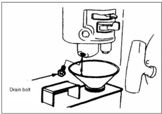
Drain engine oil after warming up the engine because such operation can ensure a quick and complete drainage of oil:
- Loosen engine oil dipstick and oil drain bolt to drain the engine oil.
- Screw back the oil drain bolt and tighten it.
- Refill the engine with recommended engine oil and check engine oil level.
- Refit the engine oil dip stick.
• The volume of engine oil shall be 0.6 L.
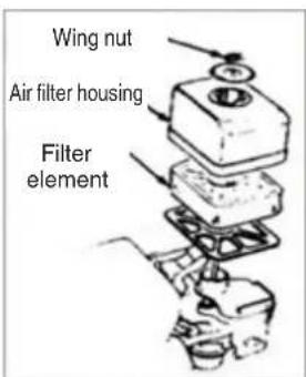
6.2. MAINTENANCE OF AIR FILTER
A dirty air filter will obstruct air into the carburetor. So in order to prevent fault of carburetor, the air filter shall be maintained regularly. If the engine is to work in a dusty environment, its maintenance frequency should be increased.

Warning!
Never use gasoline or low-burning-point detergent to clean air filter element because they may cause burning.
MAINTAIN AIR CLEANER
Clean up in cleansing solvent and dry up once every 50 hours (every 10 hours in unusually dusty circumstances) and then immerse in clean engine oil until saturated, squeeze out excessive oil
Note: never try to run the engine without an air filter, because such operation would cause quick wear of the engine.
• Take apart the wing nut and air filter housing and take out the filter element.
- Use an uninflammable or high-burning-point detergent to clean filter element and let it dry up.
- Drench filter element with engine oil and then squeeze the oil out.
- Refit filter element and air filter housing.
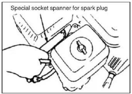
6.3. MAINTENANCE OF SPARK PLUG
Note: Never use any spark plug with an incorrect heat range. In order to guarantee normal running of the engine, the spark plug shall have an appropriate gap without deposit on it.
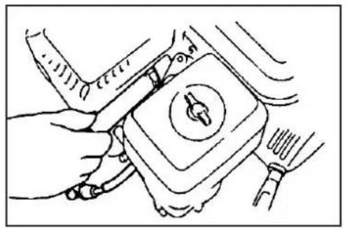
- Use a special socket spanner to detach the spark plug.
natural_image
Line drawing of a hand using a tool to adjust or install a mechanical component (no text or symbols visible)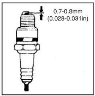

Warning!
- If the engine has just stopped running, the muffler will be very hot. So keep clear of hot temperature to avoid scald.
- Check the spark plug. If it is obviously worn or the insulation has any crack or damage, please replace it, if it has too much carbon deposition; use a wire brush to clean it.
- Use a clearance gauge to measure the spark plug gap, correct value of which shall be 0.70 to 0.80mm.
- Check whether spark plug washer is good. In order to avoid thread alternating, use hand to screw spark plug in first.
- After screwing spark plug to the bottom, use a special socket spanner to tighten it and the washer below it.
Note: If the spark plug is a new one, tighten the spark plug further by 1/2 turn after the washer is pressed down tightly.
If the spark plug has been used, tighten it further by 1/8 - 1/4 turn after the washer is pressed down tightly.
The spark plug must be tightened adequately, or it will be heated and damage the engine.

Warning!
If the engine has just stopped running, the muffler will be very hot. Don't work on the engine before it has cooled.
Note: Spark arrester must be maintained every 100 hours to ensure it can work effectively.
- Loosen out two 4mm screws from the exhaust deflection pipe and take apart the exhaust deflection pipe.
- Loosen out four 5mm screws from the muffler guard to detach the muffler guard.
- Loosen out the 4mm screws from the spark arrester to detach it from the muffler.
- Use a brush to remove carbon deposition from the mesh enclosure of the spark arrester.
Note: No cracks or damage in the spark arrester is allowed. If there is any crack or damage, replace the spark arrester.
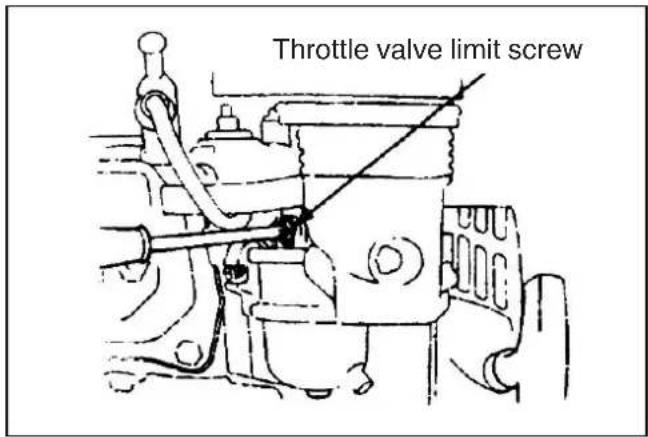
6.4. IDLING ADJUSTMENT OF THE CARBURETOR
- Start the engine to warm it up to the normal temperature.
- When engine is idle running, adjust the throttle valve's limit screw to set the normal idling speed.
Normal idling speed: 1800±150rmp
7. MAINTENANCE OF TILLER
Due to wear from running, friction and change of load, the tiller's bolts may get loose, and parts and components may get worn, causing lower power of the gasoline engine, higher fuel consumption rate and other faults that will affect use of the tiller. In order to keep the above adverse conditions to a minimum level, it is necessary to strictly and regularly conduct maintenance of the tiller, so that it can maintain a good technical condition and have a longer service life.
7.1. RUNNING IN
- Please refer to the manual for information about running-in of the gasoline engine.
- A new or overhauled tiller shall work for one hour without load first, then work for another nine hours, then the machine can be used for normal farming.
7.2. TECHNICAL MAINTENANCE OF TILLER

Warning!
Before commencing any inspections, cleaning or maintenance/adjustments on the machine:
- Stop the machine and turn off the engine.
- Make sure that any moving component has stopped.
-
Wait until the engine cools down.
-
Maintenance per shift (before and after each shift of work):
a) Listen and watch to check if there is any abnormal phenomenon like abnormal noise, overheating, loose bolts, etc.
b) Check if there is any oil leakage from the gasoline engine.
c) Check if oil levels of the gasoline engine are between the upper and lower marks of its oil level indicators
d) Timely remove dirt, slime, weeds and oil stains on the whole machine and its accessories.
e) Keep the farming record.
- First-level maintenance (every 150 hours of work):
a) Conduct all items of maintenance for each shift.
b) Clean reduction box, and change grease
- Second-level maintenance (every 800 hours of work):
a) Conduct all items of the maintenance for every 150 hours of work.
b) Check all gears and bearings, if any of them is severely worn, replace it.
c) If any of the tiller's other parts and components, such as any tilling blade or bolt, is damaged, please replace it.
- Technical check and repair (every 1500-2000 hours of work):
a) Disassemble the whole machine at a local authorized service shop to clean and check it, and if any of the parts and components is severely worn, replace it or repair it if it is appropriate to do so.
- Repair and maintenance of gasoline engine shall be conducted as per the manual.
7.3. TABLE OF MINI-TILLER'S TECHNICAL MAINTENANCE
(AN ITEM MARKED WITH √ SHALL BE MAINTAINED)
| Content of maintenance\Work interval | Every day | After 8 hours of work under a half load | After the first month or after 20 hours | After the third month or after 150 hours | Every year or 1,000 hours | Every 2 years or 2,000 hours |
| Check and tighten bolts and nuts | √ | |||||
| Check and add new engine oil | √ | |||||
| Clean and change engine oil | (First time) (Second time) | √(third time and thereafter) | ||||
| Check if there's oil leakage | √ | |||||
| Clean dirt, weeds, and oil stains | √ | |||||
| Solve problems | √ | |||||
| Adjust operating parts √ | ||||||
| Tension belt (*) | √ | |||||
| Gears and bearings (*) | √ | |||||
(*) Interventions that must be carried out by your Dealer or by an Authorised Service Centre
7.4. LONG STORAGE OF MINI-TILLER
If the tiller need be stored for a long time, the following measures should be taken to prevent rust and erosion.
- Seal up and store gasoline engine as per requirements in the manual of gasoline engine.
- Clean dirt and slime on the outer surface.
- Drain lubricant from the transmission box and fill it with new lubricant.
- Apply anti-corrosion oil on unpainted part of the non-aluminum-alloy surface.
- Keep the product in a well ventilated, dry and safe indoor place.
- Properly keep the tools, quality certificate and operation manual attached to the machine.
7.5. TRANSPORT
A forklift truck should be used to move the machine. The forks should be opened as far as possible and inserted into the pallet. The weight of the machine is given on the Manufacturer's data plate together with the other technical information.
Motor-hoe can be transported to given place by means of transport wheel (Fig 1 part. 3).
Switch off the engine before transporting the machine
8. TROUBLE SHOOTING
If the engine can't be started, please check
- Whether the engine switch is in the ON position,
- Whether there is enough lubricant in the machine,
- Whether fuel valve is in the ON position,
- Whether there is fuel in the fuel tank,
- Whether fuel can be delivered into carburetor, to check this, the user can loosen drain bolt of carburetor and set the fuel valve to the ON position.

Warning!
If any fuel is spilled out, thoroughly remove it and let it dry up before checking spark plug or starting the engine, because fuel spilled out and its vapor may cause a fire.
- Whether the spark plug can spark.
a) Pull off the spark plug cap, remove dirt from it, then detach the spark plug.
b) Fit spark plug cap over the spark plug.
c) Contact the metallic case of spark plug to engine's cylinder head. Slightly pull the starter to check if sparks are produced. If so, refit the spark plug and start the engine.
- If the engine still cannot start, please repair it at an authorized distributor's shop.

¡ATENCIÓN!
natural_image
Close-up of a hand adjusting a mechanical component with a circular valve (no visible text or symbols)Figura 2 Tabla 1
bar
| Temperature (°C) | 20W/40 | 10W/30 | 10W | 20W | 20 | 30 | 40 | |---|---|---|---|---|---|---|---| | -30 | - | - | - | - | - | - | - | | -20 | - | - | - | - | - | - | - | | -10 | - | - | - | - | - | - | - | | 0 | 40 | 35 | 30 | 10 | 80 | 90 | 100 | | 100 | 40 | 35 | 30 | 10 | 80 | 90 | 100 | Legend: Solid black bars = "Cantidad accomendada", Dotted red line = "Cantidad limit utilizable".natural_image
Close-up of a hand adjusting a mechanical component with a circular housing and bolted joints (no visible text or symbols)Figura 4
- Control filtro del aire

¡Atención!
natural_image
Close-up of a mechanical clamp or bracket with a metal wire inserted, no visible text or symbols
natural_image
Close-up of a mechanical assembly with metal blades and wiring (no visible text or symbols)Figura 5 Figura 6
natural_image
Mechanical lever handle assembly with black and gray components (no text or symbols visible)
natural_image
Mechanical lever handle and grip assembly (no text or symbols visible)Figura 7 Figura 8
natural_image
Mechanical assembly diagram showing a belt drive system with pulleys and gears (no text or symbols)Figura 10 Tuercas del motor
natural_image
Mechanical assembly diagram showing motor and gear components with no visible text or symbolsFigura 11 Tuercas del motor
natural_image
3D rendering of a black automotive lever handle and grip (no text or symbols visible)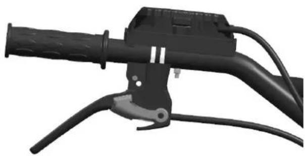
natural_image
Close-up of a black automotive brake lever handle and grip (no text or symbols visible)Figura 14 Figura 15
natural_image
Close-up of a mechanical vehicle's wheel and suspension components (no visible text or symbols)Figura 15 Figura 16

natural_image
Mechanical assembly diagram showing a motor, crankshaft, and fan blade (no text or symbols)5. ARRANQUE
5.1. CÓMO PONER EN MARCHA LA MÁQUINA

¡Atención!
natural_image
Line drawing of a hand using a tool to adjust or install a mechanical component (no text or symbols visible)

¡Atención!

TÄHELEPANU!
natural_image
Close-up of a hand adjusting a mechanical component with a circular tool (no visible text or symbols)Joonis 2 Tabel 1
bar
| Oil Temperature (°C) | Scavellad kogus (°C) | Kapulesa prinogus (°C) | |---|---|---| | 20W/40 | -15 | 38 | | 10W/30 | -15 | 30 | | 10W | -10 | 5 | | 20W | -10 | 10 | | 20 | 20 | 20 | | 30 | 20 | 30 | | 40 | 35 | 40 |natural_image
Close-up of a hand adjusting a mechanical component with a circular housing and mounting bracket (no visible text or symbols)Joonis 4
- Ôhufiltri kontroll

Tähelepanu!
natural_image
Close-up of a mechanical clamp or bracket with metal wire and clamping tool (no text or symbols visible)
natural_image
Close-up of a mechanical device with attached components and mounting brackets (no visible text or symbols)Joonis 5 Joonis 6
natural_image
Mechanical lever handle assembly with black and gray components (no text or symbols visible)
natural_image
Mechanical lever handle and grip assembly (no text or symbols visible)Joonis 7 Joonis 8
natural_image
Mechanical assembly showing a belt drive system with pulleys and gears (no visible text or symbols)Joonis 10 Mootorimutrid

natural_image
Close-up mechanical assembly showing internal components and wiring (no visible text or symbols)Joonis 11 Mootorimutrid
natural_image
Two black automotive lever handle assemblies shown from front and side views (no text or symbols visible)Joonis 14 Joonis 15
natural_image
Close-up of a mechanical vehicle's wheel and suspension components (no visible text or symbols)Joonis 15 Joonis 16

natural_image
Close-up of a mechanical assembly with a wheel and attached component (no visible text or symbols)5. KÄIVITAMINE
5.1. KUIDAS MASINAT KÄIVITADA

Tähelepanu!
- Keerake kergelt gaasikangi maksimumkiiruse poole.
- Asetage mootorilülii asendisse ON (lahti).
natural_image
Line drawing of a hand using a tool to adjust or install a mechanical component (no text or symbols visible)

Tähelepanu!

VAROITUS!
natural_image
Close-up of a hand adjusting a mechanical component with a circular knob (no visible text or symbols)Kuva 2 Taulukko 1
bar
| Wind Speed | Suostellu maaat (°C) | Kayletlava rajamaata (°C) | |---|---|---| | 20W/40 | -15 | 38 | | 10W/30 | -12 | 32 | | 10W | -10 | 5 | | 20W | -5 | 10 | | 20 | 10 | 7 | | 30 | 15 | 25 | | 40 | 35 | 100 |natural_image
Close-up of a hand adjusting a mechanical component with a circular housing and bolted joints (no visible text or symbols)Kuva 4
natural_image
Close-up of a mechanical clamp or bracket with metal wire and clamping tool (no text or symbols visible)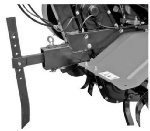
natural_image
Close-up of a mechanical agricultural machine component with no visible text or symbolsKuva 5 Kuva 6
natural_image
Mechanical lever handle and grip assembly (no text or symbols visible)
natural_image
Mechanical lever handle and grip assembly (no text or symbols visible)Kuva 7 Kuva 8
Kuva 9
natural_image
Mechanical assembly showing a belt drive system with pulleys and gears (no visible text or symbols)natural_image
Close-up mechanical assembly showing internal components and wiring (no visible text or symbols)natural_image
Two black automotive lever handle assemblies shown from front and side views (no text or symbols visible)Kuva 14 Kuva 15
natural_image
Close-up of a mechanical vehicle's wheel and suspension components (no visible text or symbols)Kuva 15 Kuva 16

natural_image
Close-up of a mechanical component with a wheel and attached fan (no visible text or symbols)5. KÄYNNISTYS
5.1. MITEN KONE KÄYNNISTETÄÄN

Varoitus!
natural_image
Line drawing of a hand using a tool to adjust or install a mechanical component (no text or symbols visible)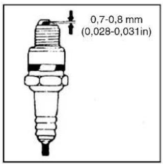

Varoitus!

ATTENTION!
natural_image
Close-up of a hand adjusting a mechanical component with a circular valve (no visible text or symbols)Figure 2 Tableau 1

bar
| Temperature (°C) | Quantité recommandés (°C) | Quantité limite utilisable (°C) | |---|---|---| | 20W/40 | -15 | 38 | | 10W/30 | -15 | 30 | | 10W | -10 | 0 | | 20W | -5 | 10 | | 20 | 5 | 20 | | 30 | 10 | 25 | | 40 | 35 | 40 |natural_image
Close-up of a hand adjusting a mechanical component with a circular housing and mounting bracket (no visible text or symbols)Figure 4
natural_image
Close-up of a mechanical clamp or bracket with a metal wire inserted, no visible text or symbols
natural_image
Close-up of a mechanical agricultural machine with metal blades and mounting bracket (no visible text or symbols)Figure 5 Figure 6
natural_image
Close-up of a black bicycle brake lever handle and grip (no text or symbols visible)
natural_image
Mechanical lever handle and grip assembly (no text or symbols visible)Figure 7 Figure 8
natural_image
Mechanical assembly diagram showing a belt drive system with pulleys and gears (no text or symbols)natural_image
Mechanical assembly diagram showing motor, gear, and housing components with no visible text or symbolsnatural_image
3D rendered image of a black mechanical lever handle and grip assembly (no text or symbols visible)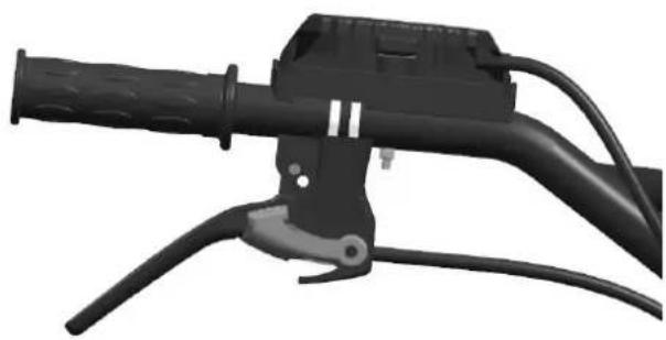
natural_image
Close-up of a black automotive brake lever handle and cable (no text or symbols visible)Figure 14 Figure 15
natural_image
Close-up of a mechanical vehicle's wheel and suspension components (no visible text or symbols)Figure 15 Figure 16

natural_image
Close-up of a mechanical engine component with visible blades and housing (no text or symbols)5. DÉMARRAGE
5.1. COMMENT DÉMARRER LA MACHINE

Attention!
natural_image
Line drawing of hands operating a mechanical device with a knob (no text or symbols)

Attention!


POZOR!
Prije korištenja strojem pročitajte upute
natural_image
Close-up of a hand adjusting a mechanical component with a circular tool (no visible text or symbols)Slika 2 Tablica 1

bar
| Temperature (°C) | Propručena količina (°C) | Grančna luperativa količina (°C) | |---|---|---| | 20W/40 | -10 | 38 | | 10W/30 | -15 | 30 | | 10W | 0 | 0 | | 20W | 10 | 0 | | 20 | 20 | 0 | | 30 | 25 | 0 | | 40 | 35 | 0 |-
Kontrolirajte mazivo u kućištu reduktora
-
Namjestite motornu kopačicu na horizontalnu površinu i skinite čep (vidi sl. 4).
- Preporučujemo dodavanje pogodnog maziva za kućište reduktora svakih 50 sati.
- Preporučeno mazivo je mast na bazi kalcija.
natural_image
Close-up of a hand adjusting a mechanical component with a circular housing and mounting bracket (no visible text or symbols)Slika 4
natural_image
Close-up of a mechanical clamp or bracket with metal wire and clamping tool (no text or symbols visible)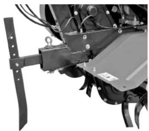
natural_image
Close-up of a mechanical assembly with metal blades and mounting brackets (no visible text or symbols)Slika 5 Slika 6
natural_image
Close-up of a black bicycle brake lever handle and grip (no text or symbols visible)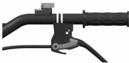
natural_image
Mechanical lever handle and grip assembly (no text or symbols visible)Slika 7 Slika 8
- Kad rukovatelj otpusti ručicu spojke, spojka se deaktivira i struja se s motora ne prenosi motornoj kopačici, a noževi se prestaju okretati (vidi sl. 8).
natural_image
Mechanical assembly showing a belt drive system with pulleys and gears (no visible text or symbols)Slika 10 Matice motora

natural_image
Close-up mechanical assembly showing internal components and wiring (no visible text or symbols)Slika 11 Matice motora
5. Podešavanje kabela gasa:
- Normalna brzina: 1800±100 o/min; povećana brzina: 3000±50 o/min. Brzinu možete podesiti pomoću brojača okretaja.
- Način kontrole i podešavanje brzine. Podešavanje kabela gasa
Slika 12 Slika 13
Ručica gasa
- Okrenite ručicu gasa na ručki za upravljanje na maksimum bez opterećenja i provjerite pokazuje li brojač okretaja brzinu između 3600±50 o/min. Zatim okrenite ručicu na minimum i provjerite pokazuje li brojač okretaja brzinu od 1800±100 o/min.
- Ako brzina koju pokazuje brojač okretaja nije u naznačenim granicama, treba podesiti motor.
Podešavanje motora:
a) Kontrolirajte da spojevi kabela gasa nisu popustili ili puknuli. Ako jesu, ponovno ih zategnite.
b) Okrenite ručicu gasa na ručki za upravljanje na maksimum bez opterećenja, zatim smanjite brzinu podešavajući matice mehanizma za ubrzavanje motora sve do odgovarajućeg položaja.
c) Nakon mnogo sati rada rukovatelj može podesiti matice za kabel gasa kako bi podesio motor.
natural_image
3D rendered image of a black automotive lever handle and grip assembly (no text or symbols visible)
natural_image
Close-up of a black automotive brake lever with handle and lever arms (no text or symbols visible)Slika 14 Slika 15
- Kad rukovatelj otpusti ručicu spojke, spojka se deaktivira i struja se s motora ne prenosi motornoj kopačici, a noževi se prestaju okretati (vidi sl. 15).
Napomena: Prilikom uporabe ručice sustava za kretanje unatrag postupajte na siguran način. Nepravilno podešen kabel spojke ugrožava normalnu uporabu proizvoda.
-
Podešavanje prednjeg kotača:
-
Podesite prednji kotač motorne kopačice u položaj koji se vidi na sl. 15 prilikom putovanja po cesti.
- Podesite prednji kotač motorne kopačice u položaj koji se vidi na sl. 16 prilikom putovanja po polju.
natural_image
Close-up of a mechanical device with wheels and mounting brackets (no visible text or symbols)Slika 15 Slika 16

natural_image
Close-up of a mechanical engine component with visible blades and hub (no text or symbols)5. POKRETANJE
5.1. KAKO POKRENUTI STROJ

Pozor!
natural_image
Line drawing of hands using a tool to adjust or install a mechanical component (no text or symbols visible)

Pozor!

FIGYELEM!
natural_image
Close-up of a hand adjusting a mechanical component with a circular tool (no visible text or symbols)- ábra 1. táblázat

bar
| Power Level | Alaniott mannyiség (°C) | Hasznatall hasznendős (°C) | |---|---|---| | 20W/40 | -15 | 38 | | 10W/30 | -15 | 30 | | 10W | -5 | 0 | | 20W | -10 | 10 | | 20 | 5 | 80 | | 30 | 15 | 25 | | 40 | 35 | 40 | Hörnéséketnatural_image
Close-up of a hand adjusting a mechanical component with a circular housing and bolts (no visible text or symbols)natural_image
Close-up of a mechanical clamp or bracket assembly with metal rods and a curved handle (no text or symbols visible)
natural_image
Close-up of a mechanical assembly with metal brackets and mounting feet (no visible text or symbols)- ábra 6. ábra
natural_image
Mechanical lever handle assembly with black and gray components (no text or symbols visible)
natural_image
Mechanical lever handle and grip assembly (no text or symbols visible)7. ábra 8. ábra
natural_image
Mechanical assembly showing a belt drive system with pulleys and gears (no visible text or symbols)- ábra Motor anyák

natural_image
Close-up mechanical assembly showing internal components and wiring (no visible text or symbols)Gázkar
natural_image
Two black automotive lever handle assemblies shown from front and side views (no text or symbols visible)- ábra 15. ábra
natural_image
Close-up of a mechanical vehicle's wheel and suspension components (no visible text or symbols)- ábra 16. ábra

natural_image
Close-up of a mechanical component with a wheel and attached fan (no visible text or symbols)5. INDÍTÁS
5.1. A GÉP BEINDÍTÁSA

Figyelem!
natural_image
Line drawing of hands using a tool to adjust or install a mechanical component (no text or symbols visible)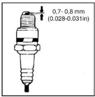

Figyelem!

DÈMESIO!
natural_image
Close-up of a hand adjusting a mechanical component with a circular knob (no visible text or symbols)natural_image
Close-up of a hand adjusting a mechanical component with a circular housing and bolts (no visible text or symbols)4 paveikslas
- Oro filtro patikrinimas

Dèmesio!
natural_image
Close-up of a mechanical clamp or bracket with a metal wire inserted, no visible text or symbols
natural_image
Close-up of a mechanical assembly with metal components and mounting brackets (no visible text or symbols)natural_image
Close-up of a black bicycle brake lever handle and grip (no text or symbols visible)
natural_image
Close-up of a black bicycle brake lever handle and grip (no text or symbols visible)natural_image
Mechanical assembly showing a belt drive system with pulleys and gears (no visible text or symbols)natural_image
Close-up mechanical assembly showing motor, gear, and housing components (no visible text or symbols)natural_image
Two black automotive lever handle assemblies shown from front and side views (no text or symbols visible)natural_image
Close-up of a mechanical vehicle's wheel assembly (no visible text or symbols)natural_image
Close-up of a mechanical engine component with visible blades and housing (no text or symbols)5. UŽVEDIMAS
5.1. KAIP PALEISTI [RENGIN]
![STIGA SRC 585 RG - KAIP PALEISTI [RENGIN] - 1](/content/2026/04/614703/images/064612ef3caec38fe4d88744634e9cf67cab4dc390243fa4dc2e79c564b5d74d.jpg)
Dèmesio!
natural_image
Line drawing of a hand using a tool to adjust or install a mechanical component (no text or symbols visible)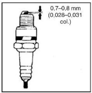
![STIGA SRC 585 RG - KAIP PALEISTI [RENGIN] - 3](/content/2026/04/614703/images/35f1d079f63f5622277d2a305898da00bee0278b38ff33d8294cc86e928b6ec7.jpg)
Dèmesio!

UZMANĪBU!
Pirms mašinas izmantošanas uzmanīgi izlasiet instrukciju
natural_image
Close-up of a hand adjusting a mechanical component with a circular tool (no visible text or symbols)- attēls 1. tabula
bar
| Wind Speed | Elias daucizums (°C) | Marmalbais (°C) | |---|---|---| | 20W/40 | -10 | 38 | | 10W/30 | -15 | 30 | | 10W | 0 | 10 | | 20W | 10 | 6 | | 20 | 20 | 20 | | 30 | 25 | 15 | | 40 | 35 | 10 |natural_image
Close-up of a hand adjusting a mechanical component with a circular housing and bolts (no visible text or symbols)natural_image
Close-up of a mechanical clamp or bracket with a metal rod inserted, no visible text or symbols
natural_image
Close-up of a mechanical agricultural machine component with no visible text or symbols- attēls 6. attēls
natural_image
Mechanical lever handle assembly with black and gray components (no text or symbols visible)
natural_image
Mechanical lever handle and grip assembly (no text or symbols visible)7. attēls 8. attēls
natural_image
Mechanical assembly showing a belt drive system with pulleys and gears (no visible text or symbols)natural_image
Close-up mechanical assembly showing internal components and wiring (no visible text or symbols)natural_image
Two black automotive lever handle assemblies shown from front and side views (no text or symbols visible)natural_image
Close-up of a mechanical vehicle's wheel and suspension components (no visible text or symbols)- attēls 16. attēls
natural_image
Close-up of a mechanical assembly with a wheel and attached component (no visible text or symbols)5. IEDARBINĀŠANA
5.1. MAŠINAS IEDARBINĀŠANA

Uzmanību!
natural_image
Line drawing of a hand using a tool to adjust or install a mechanical component (no text or symbols visible)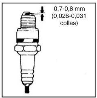

Uzmanību!

ВНИМАНИЕ!
natural_image
Close-up of a hand adjusting a mechanical component with visible wiring and mounting holes (no text or symbols)Слика 2 Табела 1
bar
| Temperature (°C) | Pre-Saturation (°C) | Post-Saturation (°C) | |---|---|---| | 20W/40 | -15 | 38 | | 10W/30 | -15 | 30 | | 10W | -10 | 0 | | 20W | -5 | 10 | | 20 | 5 | 20 | | 30 | 15 | 30 | | 40 | 35 | 40 |natural_image
Close-up of a hand adjusting a mechanical component with a bolt and housing (no visible text or symbols)Слина 4
natural_image
Close-up of a mechanical clamp or bracket with metal wire and clamping mechanism (no text or symbols visible)
natural_image
Close-up of a mechanical agricultural machine with visible blades and mounting brackets (no text or symbols)Слика 5 Слика 6
natural_image
3D rendering of a black bicycle brake lever handle and grip (no text or symbols visible)
natural_image
Close-up of a black bicycle brake lever handle and lever (no text or symbols visible)Слина 7 Слина 8
natural_image
Mechanical assembly diagram showing a belt drive system with pulleys and gears (no text or symbols)natural_image
Mechanical assembly diagram showing motor, gear, and housing components with no visible text or symbolsnatural_image
3D rendered image of a black automotive lever handle and grip assembly (no text or symbols visible)
natural_image
Close-up of a black automotive brake lever with handle and cable (no visible text or symbols)Слина 14 Слина 15
natural_image
Close-up of a mechanical component with visible wheels and mounting brackets (no text or symbols)Слика 15 Слика 16

natural_image
Close-up of a mechanical engine component with visible blades and housing (no text or symbols)5. ПАЛЕЊЕ
natural_image
Line drawing of a hand using a tool to adjust or install a mechanical component (no text or symbols visible)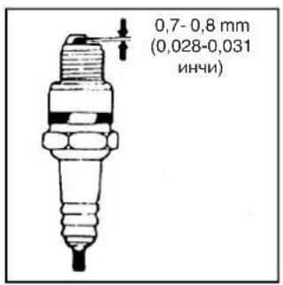

Внимание!
8. PROBLEEMOPLOSSING 18

Let op!


LET OP!
natural_image
Close-up of a hand adjusting a mechanical component with a circular tool (no visible text or symbols)natural_image
Close-up of a hand adjusting a mechanical component with a circular housing and bolted joints (no visible text or symbols)Afbeelding 4
- Controle luchtfilter

Let op!
natural_image
Close-up of a mechanical clamp or bracket assembly with metal tubing and a curved handle (no text or symbols visible)
natural_image
Close-up of a mechanical assembly with metal components and mounting brackets (no visible text or symbols)natural_image
Mechanical lever handle assembly with black and gray components (no text or symbols visible)
natural_image
Mechanical lever handle and grip assembly (no text or symbols visible)natural_image
Mechanical assembly showing a belt drive system with pulleys and gears (no visible text or symbols)natural_image
Close-up mechanical assembly showing motor, gear, and housing components (no visible text or symbols)Versnellingshendel
natural_image
3D rendered image of a black mechanical lever handle and grip (no text or symbols visible)
natural_image
Close-up of a black automotive brake lever handle and grip (no text or symbols visible)natural_image
Close-up of a mechanical device with wheels and mounting brackets (no visible text or symbols)natural_image
Close-up of a mechanical engine component with visible blades and housing (no text or symbols)5. START
5.1. HOE DE MACHINE STARTEN

Let op!
5.2. HOE DE MOTOR STOPPEN
6. ONDERHOUD VAN DE BENZINEMOTOR

Let op!
natural_image
Line drawing of a hand using a tool to adjust or install a mechanical component (no text or symbols visible)

Let op!
8. PROBLEEMOPLOSSING
7. VEDLIKEHOLD AV FILTERET 16
7.1. GJENNOMTESTING 16
7.2. TEKNISK VEDLIKEHOLD AV MOTORHAKKEN 16
7.3. TEKNISK VEDLIKEHOLDSTABELL FOR MINI-MOTORHAKKEN (DET MÅ UTF∅RES VEDLIKEHOLD VED FANEN INDIKERT MED √) 17
7.4. LANGTIDS OPPBEVARING AV MINI-MOTORHAKKEN 17
7.5. TRANSPORT....17
8. PROBLEML∅SNINGER 18

Advarsel!
1.4. REPARASJON, VEDLIKEHOLD OG OPPBEVARING

ADVARSEL!
natural_image
Close-up of a hand adjusting a mechanical component with a circular tool (no visible text or symbols)Figur 2 Tabell 1
natural_image
Close-up of a hand adjusting a mechanical component with a circular housing and bolts (no visible text or symbols)Figur 4
natural_image
Close-up of a mechanical clamp or bracket with metal wire and clamping tool (no text or symbols visible)
natural_image
Close-up of a mechanical assembly with metal blades and mounting brackets (no visible text or symbols)Figur 5 Figur 6
natural_image
Mechanical lever handle and grip assembly (no text or symbols visible)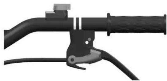
natural_image
Mechanical lever handle and grip assembly (no text or symbols visible)Figur 7 Figur 8
natural_image
Mechanical assembly showing a belt drive system with pulleys and gears (no visible text or symbols)Figur 10 Motormutre

natural_image
Close-up mechanical assembly showing internal components and mounting brackets (no visible text or symbols)Figur 11 Motormutre
natural_image
Two black automotive lever handle assemblies shown from front and side views (no text or symbols visible)Figur 14 Figur 15
natural_image
Close-up of a mechanical vehicle's wheel and suspension components (no visible text or symbols)Figur 15 Figur 16

natural_image
Close-up of a mechanical component with a wheel and attached fan (no visible text or symbols)5. OPPSTART
5.1. HVORDAN STARTE MASKINEN

Advarsel!
Før du starter motoren, skal girspaken stå i nøytral stilling. Clutchspaken må slippes opp.
VEDLIKEHOLD AV LUFTFILTERET
6.3. VEDLIKEHOLD AV TENNPLUGGEN
natural_image
Line drawing of a hand using a tool to adjust or install a mechanical component (no text or symbols visible)

Advarsel!
7. VEDLIKEHOLD AV FILTERET
(DET MÅ UTF∅RES VEDLIKEHOLD VED FANEN INDIKERT MED √)
- at tennpluggen genererer gnisten.

OSTRZEŻENIE!
natural_image
Close-up of a hand adjusting a mechanical component with a circular tool (no visible text or symbols)Rysunek 2 Tabela 1

bar
| Temperature (°C) | Ilość oleju | |---|---| | 20W/40 | -10 | | 10W/30 | -15 | | 10W | 0 | | 20W | -5 | | 20 | 10 | | 30 | 15 | | 40 | 30 | | 40 | 40 |natural_image
Close-up of a hand adjusting a mechanical component with a circular housing and bolted joints (no visible text or symbols)Rysunek 4
natural_image
Close-up of a mechanical clamp or bracket assembly with metal tubing and a curved handle (no text or symbols visible)
natural_image
Close-up of a mechanical agricultural machine component with no visible text or symbolsRysunek 5 Rysunek 6
natural_image
Mechanical lever handle and grip assembly (no text or symbols visible)
natural_image
Mechanical lever handle and grip assembly (no text or symbols visible)Rysunek 7 Rysunek 8
natural_image
Mechanical assembly showing a belt drive system with pulleys and gears (no visible text or symbols)natural_image
Close-up mechanical assembly showing internal components and wiring (no visible text or symbols)natural_image
3D rendering of a black automotive lever handle and grip assembly (no text or symbols visible)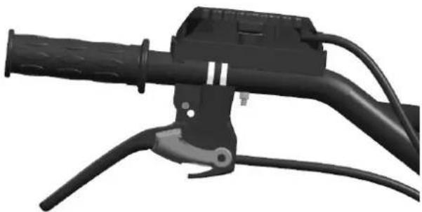
natural_image
Close-up of a black automotive brake lever handle and grip (no text or symbols visible)natural_image
Close-up of a mechanical device with wheels and brackets (no visible text or symbols)natural_image
Close-up of a mechanical assembly with a wheel and propeller (no visible text or symbols)5. ROZRUCH
5.1. JAK URUCHOMIĆ MASZYNE

Ostrzeżenie!
natural_image
Line drawing of a hand using a tool to adjust or install a mechanical component (no text or symbols visible)

Ostrzeżenie!

ATENÇÃO!
natural_image
Close-up of a hand adjusting a mechanical component with a circular tool (no visible text or symbols)Figura 2 Tabela 1
bar
| Temperature (°C) | Quantity de óleo (T) | Quantity de limbo (T) | Utilizável (T) | |---|---|---|---| | 20W/40 | -15 | -30 | -10 | | 10W/30 | -10 | -25 | -5 | | 10W | -5 | -15 | 0 | | 20W | 0 | 10 | 5 | | 20 | 5 | 20 | 10 | | 30 | 10 | 30 | 20 | | 40 | 15 | 40 | 30 |natural_image
Close-up of a hand adjusting a mechanical component with a circular housing and mounting bracket (no visible text or symbols)Figura 4
natural_image
Close-up of a mechanical clamp or bracket with a metal wire inserted, no visible text or symbols
natural_image
Close-up of a mechanical agricultural machine with metal blades and mounting bracket (no visible text or symbols)Figura 5 Figura 6
natural_image
Mechanical lever handle assembly with black and gray components (no text or symbols visible)
natural_image
Mechanical lever handle and grip assembly (no text or symbols visible)Figura 7 Figura 8
natural_image
Mechanical assembly diagram showing a belt drive system with pulleys and gears (no text or symbols)Figura 10 Porcas do motor
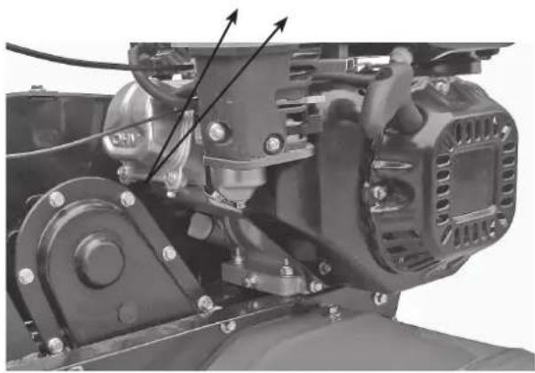
natural_image
Mechanical assembly diagram showing motor components and wiring (no text or labels visible)Figura 11 Porcas do motor
Para regular o motor:
natural_image
3D rendered image of a black automotive lever handle and grip (no text or symbols visible)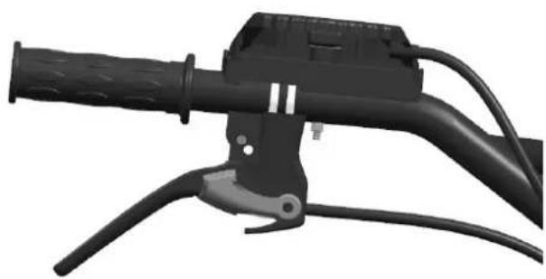
natural_image
Close-up of a black automotive brake lever handle and cable (no text or symbols visible)Figura 14 Figura 15
natural_image
Mechanical component with a wheel and attached bracket (no visible text or symbols)Figura 15 Figura 16
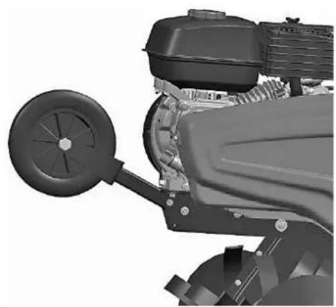
natural_image
Close-up of a mechanical engine component with visible blades and housing (no text or symbols)5. ARRANQUE
5.1. COMO INICIAR A MÁQUINA

Atenção!
natural_image
Line drawing of a hand using a tool to adjust or install a mechanical component (no text or symbols visible)

Atenção!
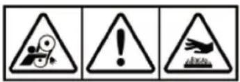

ATENTIE!
natural_image
Close-up of a hand adjusting a mechanical component with a circular valve (no visible text or symbols)Figura 2 Tabelul 1

bar
| Cantitate de uel | Limita cantitate | Limita recomandava | |---|---|---| | 20W/40 | 38 | -15 | | 10W/30 | 30 | -10 | | 10W | 0 | -15 | | 20W | 10 | -5 | | 20 | 20 | 5 | | 30 | 15 | 10 | | 40 | 35 | 25 | The chart displays a horizontal bar chart with two categories: 'Limita cantitate' and 'unliquidable'. The x-axis represents temperature in °C, ranging from -30 to 100. The bars are shaded with diagonal hatching, indicating the magnitude of each value. The legend defines the legend as 'Limita cantitate' (dotted line) and 'unliquidable' (dashed line). The chart is labeled with the number of units (e.g., 20W/40, 10W/30).natural_image
Close-up of a hand adjusting a mechanical component with a circular housing and bolted joints (no visible text or symbols)Figura 4
natural_image
Close-up of a mechanical clamp or bracket assembly with metal tubing and a curved handle (no text or symbols visible)
natural_image
Close-up of a mechanical agricultural machine component with no visible text or symbolsFigura 5 Figura 6
natural_image
Close-up of a black bicycle brake lever handle and grip (no text or symbols visible)
natural_image
Close-up of a black bicycle brake lever handle and grip (no text or symbols visible)Figura 7 Figura 8
natural_image
Mechanical assembly diagram showing a belt drive system with pulleys and gears (no text or symbols visible)natural_image
Mechanical assembly diagram showing motor components and wiring (no text or labels visible)natural_image
Two black automotive lever handle assemblies shown from front and side views (no text or symbols visible)Figura 14 Figura 15
natural_image
Close-up of a mechanical vehicle's wheel and suspension components (no visible text or symbols)Figura 15 Figura 16
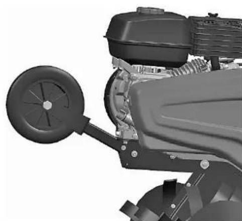
natural_image
Close-up of a mechanical engine component with visible blades and housing (no text or symbols)5. PORNIREA
5.1. CUM SE PORNEŞTE MAŞINA

Atentie!
natural_image
Line drawing of a hand using a tool to adjust or install a mechanical component (no text or symbols visible)

Atentie!
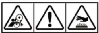
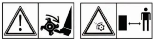
ВНИМАНИЕ!
natural_image
Close-up of a hand adjusting a mechanical component with a circular valve (no visible text or symbols)Рисунок 2 Таблица 1

bar
| Temperature (°C) | Recommended temp (°C) - количества | Predельно допустима количества | |---|---|---| | 20W/40 | 38 | -15 | | 10W/30 | 30 | -10 | | 10W | 0 | -15 | | 20W | 10 | -20 | | 20 | 20 | -15 | | 30 | 30 | -10 | | 40 | 35 | -5 |natural_image
Close-up of a hand adjusting a mechanical component with a circular housing and bolted joints (no visible text or symbols)Рисунок 4
natural_image
Close-up of a mechanical clamp or bracket assembly with metal tubing and a curved handle (no text or symbols visible)
natural_image
Close-up of a mechanical agricultural machine component with no visible text or symbolsРисунок 5 Рисунок 6
natural_image
Mechanical lever handle and grip assembly (no text or symbols visible)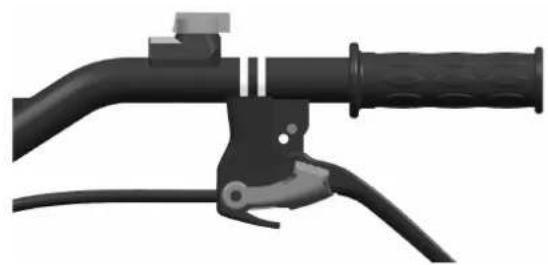
natural_image
Mechanical lever handle and grip assembly (no text or symbols visible)Рисунок 7 Рисунок 8
natural_image
Mechanical assembly diagram showing a belt drive system with pulleys and gears (no text or symbols)natural_image
Mechanical assembly diagram showing motor and gear components with no visible text or symbolsnatural_image
3D rendered image of a black automotive lever handle and grip assembly (no text or symbols visible)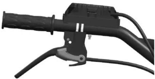
natural_image
Close-up of a black automotive brake lever handle and grip (no text or symbols visible)natural_image
Close-up of a mechanical vehicle's wheel and suspension components (no visible text or symbols)natural_image
Close-up of a mechanical engine component with visible blades and housing (no text or symbols)5. ЗАПУСК
natural_image
Line drawing of hands operating a mechanical device with a knob (no text or symbols)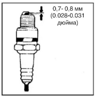

Внимание!


UPOZORNENIE!
natural_image
Close-up of a hand adjusting a mechanical component with a circular valve (no visible text or symbols)
bar
Množstvo oleja | Wind Speed | Ddoanutane mnozestro (°C) | Poultalné pravové mnozestro (°C) | | :--- | :--- | :--- | | 20W/40 | -10 | 38 | | 10W/30 | -15 | 32 | | 10W | 0 | 0 | | 20W | 10 | -5 | | 20 | 20 | 20 | | 30 | 25 | 30 | | 40 | 30 | 35 | Topolanatural_image
Close-up of a hand adjusting a mechanical component with a circular housing and bolts (no visible text or symbols)Obrázok 4
natural_image
Close-up of a mechanical clamp or bracket with metal wire and clamping tool (no text or symbols visible)Obrázok 5 Obrázok 6

natural_image
Close-up of a mechanical assembly with metal components and wiring (no visible text or symbols)natural_image
Mechanical lever handle assembly with black and gray components (no text or symbols visible)
natural_image
Mechanical lever handle and grip assembly (no text or symbols visible)Obrázok 7 Obrázok 8
natural_image
Mechanical assembly showing a belt drive system with pulleys and gears (no visible text or symbols)natural_image
Close-up mechanical assembly showing internal components and wiring (no visible text or symbols)natural_image
Two black automotive lever handle assemblies shown from front and side views (no text or symbols visible)natural_image
Close-up of a mechanical vehicle's wheel assembly with attached brackets and wheels (no visible text or symbols)natural_image
Close-up of a mechanical component with a wheel and attached fan (no visible text or symbols)5. ŠTARTOVANIE
5.1. AKO NAŠTARTOVAŤ STROJ

Upozornenie!
natural_image
Line drawing of hands using a tool to adjust or install a mechanical component (no text or symbols visible)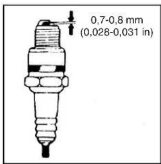

Upozornenie!


POZOR!
Preden stroj uporabite, preberite navodila NEVARNOST! Motor oddaja ogljikov monoksid. NEVARNOST! Gorivo je vnetljivo in eksplozivno.
POZOR!
natural_image
Close-up of a hand adjusting a mechanical component with a circular tool (no visible text or symbols)Slika 2 Tabela 1
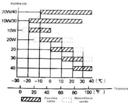
bar
| Temperature (°C) | Pijporčena količina (°C) | Mejna količina za uporbo (°C) | |---|---|---| | 20W/40 | -10 | 38 | | 10W/30 | -15 | 30 | | 10W | 0 | 0 | | 20W | 10 | 0 | | 20 | 20 | 0 | | 30 | 20 | 0 | | 40 | 35 | 0 |natural_image
Close-up of a hand adjusting a mechanical component with a circular housing and mounting bracket (no visible text or symbols)Slika 4
natural_image
Close-up of a mechanical clamp or bracket with metal wire and clamping tool (no text or symbols visible)
natural_image
Close-up of a mechanical device with attached components and mounting brackets (no visible text or symbols)Slika 5 Slika 6
3. Regulacija in uporaba sklopke:
natural_image
Mechanical lever handle assembly with black and gray components (no text or symbols visible)
natural_image
Mechanical lever handle and grip assembly (no text or symbols visible)Slika 7 Slika 8
natural_image
Mechanical assembly showing a belt drive system with pulleys and gears (no visible text or symbols)natural_image
Close-up mechanical assembly showing motor, gear, and housing components (no visible text or symbols)natural_image
3D rendered image of a black automotive lever handle and grip assembly (no text or symbols visible)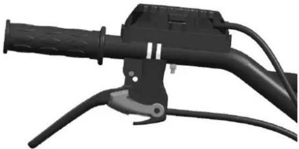
natural_image
Close-up of a black automotive brake lever handle and grip (no text or symbols visible)Slika 14 Slika 15
natural_image
Close-up of a mechanical device with wheels and levers (no visible text or symbols)Slika 15 Slika 16
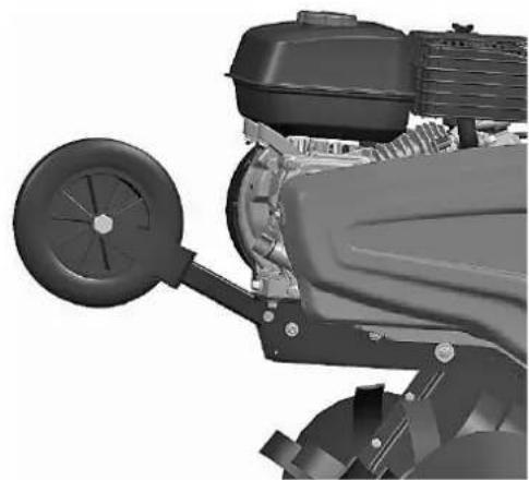
natural_image
Close-up of a mechanical assembly with a wheel and fan component (no visible text or symbols)5. ZAGON
5.1. ZAGON MOTORJA

Pozor!
- Ko se motor ogreje, ročico čoka rahlo potisnite v smeri oznake OPEN (odprto).
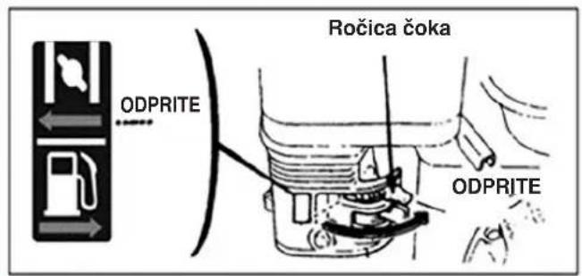
- Za reguliranje zaželene hitrosti motorja uporabite ročico plina (oziroma ročico dušilnega ventila).
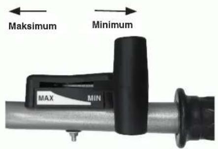
5.2. ZAUSTAVITEV MOTORJA
natural_image
Line drawing of hands using a tool to adjust or install a mechanical component (no text or symbols visible)

Pozor!
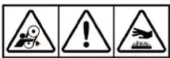

PAŽNJA!
natural_image
Close-up of a hand adjusting a mechanical component with a circular tool (no visible text or symbols)Slika 2 Tabela 1
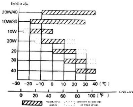
bar
| Temperature (°C) | Propručena količina | Grančna količna keja se moža korstili | |---|---|---| | 20W/40 | -10 | 38 | | 10W/30 | -15 | 32 | | 10W | 0 | 0 | | 20W | 10 | 0 | | 20 | 20 | 0 | | 30 | 25 | 0 | | 40 | 35 | 0 |- Proverite ulje u menjačkoj kutiji
- Postavite motokultivator na vodoravnu povrsinu i skinite poklopac (vidi sl. 4).
- Preporučujemo da svakih 50 sati sipate mazivo koje će odgovarati menjačkoj kutiji.
- Preporučeno mazivo je na bazi kalcijuma.

natural_image
Close-up of a hand adjusting a mechanical component with a circular housing and mounting bracket (no visible text or symbols)Slika 4
- Kontrola filtera za vazduh

Pažnja!
natural_image
Close-up of a mechanical clamp or bracket with a metal wire inserted, no visible text or symbolsSlika 5 Slika 6
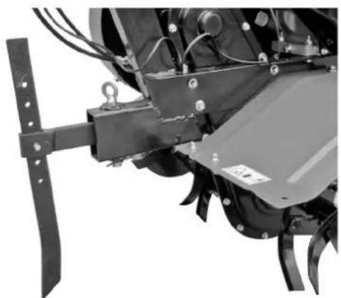
natural_image
Close-up of a mechanical agricultural machine component with no visible text or symbols3. Podešavanje i upotreba kvačila:
Napomena: pre upotrebe kvačila, smanjite brzinu motora.
natural_image
Mechanical lever handle assembly with black and gray components (no text or symbols visible)
natural_image
Mechanical lever handle and grip assembly (no text or symbols visible)Slika 7 Slika 8
natural_image
Mechanical assembly showing a belt drive system with pulleys and gears (no visible text or symbols)Slika 10 Matice motora
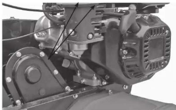
natural_image
Close-up mechanical assembly showing internal components and wiring (no visible text or symbols)Slika 11 Matice motora
5. Podešavanje kabla gasa:
- Normalna brzina: 1800±100 obrtaja/min; prevelika brzina: 3000±50 obrtaja/min. Brzina se može regulisati pomoću brojača obrtaja.
- Način kontrole i podešavanja brzine. Podešavanje kabla gasa
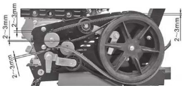
Slika 12 Slika 13
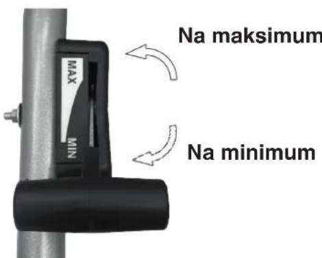
Poluga gasa
- Okrenite polugu gasa na ručici pluga do maksimuma bez opterećenja i proverite da li brojač obrtaja pokazuje brzinu između 3600±50 obrtaja/min. Potom okrenite polugu do minima i proverite da li je na brojaču prikazana brzina između 1800±100 obrtaja/min.
- Ako brzina koju pokaže brojač obrtaja nije u rasponu navedenih vrednosti, potrebno je podesiti motor.
natural_image
Two black automotive lever handle assemblies shown from front and side views (no text or symbols visible)Slika 14 Slika 15
natural_image
Close-up of a mechanical vehicle's wheel and suspension components (no visible text or symbols)Slika 15 Slika 16

natural_image
Close-up of a mechanical assembly with a wheel and attached component (no visible text or symbols)5. POKRETANJE
5.1. POSTUPAK POKRETANJA MAŠINE

Pažnja!
Pre nego što pokrenete motor, poluga menjača mora biti u leru. Treba da pustite polugu kvačila.
- Postavite polugu vazduha na CLOSE (zatvoreno).
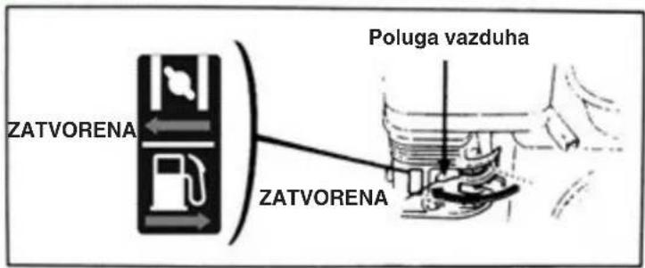
- Okrenite lagano polugu gasa na najveću brzinu.
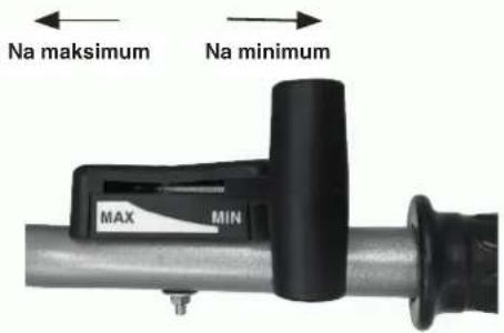
- Postavite prekidač motora na ON (otvoreno).
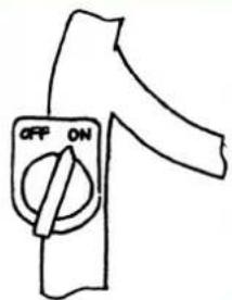
Lagano povucite kabal elektropokretača sve dok se ne opire, zatim ga brzo i snažno povucite ka vani.
Nemojte odjednom pustiti polugu jer bi ona mogla odskočiti unazad i pogoditi i oštetiti motor. Da biste polugu otpustili, pustite istu da polako klizi duž sajle za pokretanje.

- Kad se motor zagreje, lagano gurnite polugu vazduha prema OPEN (otvoriti).
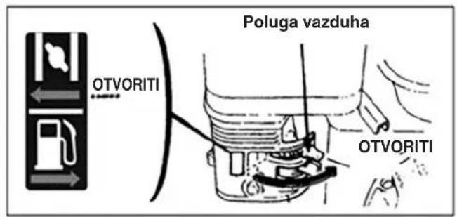
- Koristite polugu gasa (ili polugu leptirastog ventila) da biste podesili brzinu motora do potrebne vrednosti.
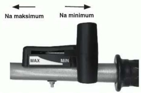
5.2. POSTUPAK ZAUSTAVLJANJA MOTORA
natural_image
Line drawing of a hand using a tool to adjust or install a mechanical component (no text or symbols visible)

Pažnja!
- Ako se motor tek zaustavio, izduvni lonac će biti veoma vruć. Držite se podalje od vrućih delova da se ne opečete.
- Proverite svećicu za paljenje. Ako je istrošena ili su se na izolatoru pojavile pukotine ili oštećenja, zamenite je; ako na njoj ima prevelikih naslaga uglja, očistite je metalnom četkom.
- Koristite merni listić da izmerite rastojanje između elektroda svećice: tačna vrednost mora biti između 0,70 i 0,80 mm.
- Proverite da li je podloška svećice za paljenje u dobrom stanju. Da ne biste oštetili navoj, rukom zavrnite svećicu za paljenje.
- Kad zavrnete svećicu za paljenje do kraja, pomoću posebnog nasadnog ključa pritegnite svećicu i donju podlošku.
1.4. REPARATION, UNDERHÅLL OCH FÖRVARING
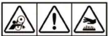

WARNING!
natural_image
Close-up of a hand adjusting a mechanical component with a circular tool (no visible text or symbols)Figur 2 Tabell 1

bar
| Temperature (°C) | Trokommenderide (nmm) | Extront antändische (mm) | other (mm) | |---|---|---|---| | 20W/40 | -15 | -10 | -5 | | 10W/30 | -10 | -5 | 0 | | 10W | -5 | 0 | 5 | | 20W | -10 | 10 | 15 | | 20 | 10 | 20 | 30 | | 30 | 20 | 30 | 40 | | 40 | 30 | 40 | 50 |natural_image
Close-up of a hand adjusting a mechanical component with no visible text or symbolsFigur 4
- Kontrollera luftfiltret

Varning!
natural_image
Close-up of a mechanical clamp or bracket with a metal wire inserted, no visible text or symbols
natural_image
Close-up of a mechanical agricultural machine component with no visible text or symbolsFigur 5 Figur 6
natural_image
Close-up of a black bicycle brake lever handle and grip (no text or symbols visible)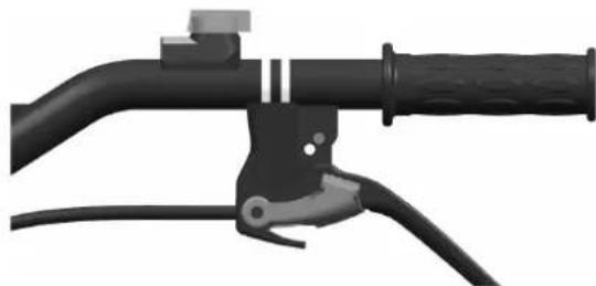
natural_image
Close-up of a black bicycle brake lever handle and grip (no text or symbols visible)Figur 7 Figur 8
natural_image
Mechanical assembly showing a belt drive system with pulleys and gears (no visible text or symbols)Figur 10 Motorns monteringsbultar

natural_image
Close-up mechanical assembly showing internal components and wiring (no visible text or symbols)Figur 11 Motorns monteringsbultar
natural_image
3D rendered image of a black automotive lever handle and grip (no text or symbols visible)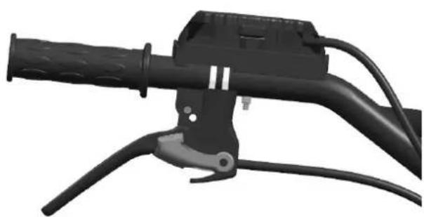
natural_image
Close-up of a black automotive brake lever handle and grip (no text or symbols visible)Figur 14 Figur 15
natural_image
Mechanical component with visible wheels and mounting brackets (no text or symbols)Figur 15 Figur 16

natural_image
Close-up of a mechanical engine component with visible blades and hub (no text or symbols)5. STARTA
5.1. STEG FÖR ATT STARTA MASKINEN

Varning!
natural_image
Line drawing of hands using a tool to adjust or install a mechanical component (no text or symbols visible)

Varning!


DİKKAT!
natural_image
Close-up of a hand adjusting a mechanical component with a circular tool (no visible text or symbols)Resim 2 Tablo 1
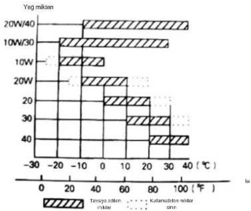
bar
Yag mikten | Temperature (W) | Taways solution (kcal/mol) | Kalamisblan mixer (kcal/mol) | | :--- | :--- | :--- | | 20W/40 | -15 | 40 | | 10W/30 | -15 | 35 | | 10W | -10 | 0 | | 20W | -10 | 10 | | 20 | 20 | 20 | | 30 | 20 | 30 | | 40 | 30 | 40 |natural_image
Close-up of a hand adjusting a mechanical component with a circular housing and mounting bracket (no visible text or symbols)Resim 4
natural_image
Close-up of a mechanical clamp or bracket with a metal wire inserted, no visible text or symbols
natural_image
Close-up of a mechanical agricultural machine component with no visible text or symbolsResim 5 Resim 6
natural_image
Mechanical lever handle assembly with black and gray components (no text or symbols visible)
natural_image
Mechanical lever handle and grip assembly (no text or symbols visible)Resim 7 Resim 8
natural_image
Mechanical assembly showing a belt drive system with pulleys and gears (no visible text or symbols)natural_image
Close-up mechanical assembly showing motor, gear, and housing components (no visible text or symbols)natural_image
Two black automotive lever handle assemblies shown from front and side views (no text or symbols visible)Resim 14 Resim 15
natural_image
Close-up of a mechanical vehicle's wheel assembly and suspension components (no visible text or symbols)Resim 15 Resim 16

natural_image
Close-up of a mechanical engine component with visible blades and housing (no text or symbols)5. ATEŞLEME
5.1. MAKİNENİN ÇALIŞTIRILMASI

Dikkat!
natural_image
Line drawing of hands using a tool to adjust or install a mechanical component (no text or symbols visible)

Dikkat!
UK Importer: STIGA LTD
CA
Unit 8, Bluewater Estate Plympton, Devon, PL7 4JH, England
| FR [Induction de la crème et leory role]Dacrimoni CE de Conforme (2004/2012), Annon II, surle A]Dacrimoni de la Coque de la Coque de la Coque de la Coque de la Coque de la Coque de la Coque de la Coque de la Coque de la Coque de la Coque de la Coque de la Coque de la Coque de la Coque de la Coque de la Coque de la Coque de la Coque de la Coque de la Coque de la Coque de la Coque de la Coque de la Coque de la CoQue de la Coque de la Coque de la Coque de la Coque de la Coque de la Coque de la Coque de la Coque de la Coque de la Coque de la Coque de la Coque de la Coque de la Coque de la Coque de la Coque de la Coque de la Coque de la Coque de la Coque de la Coque de la Coque de la Coque de la Coque de la Coue de la Coque de la Coque de la Coque de la Coque de la Coque de la Coque de la Coque de la Coque de la Coque de la Coque de la Coque de la Coque de la Coque de la Coque de la Coque de la Coque de la Coque de la Coque de la Coque de la Coque de la Coque de la Coque de la Coque de la Coque de la CoQue de la Coque de la Coque de la Coque de la Coque de la Coque de la Coque de la Coque de la Coque de la Coque de la Coque de la Coque de la Coque de la Coque de la Coque de la Coque de la Coque de la Coque de la Coque de la Coque de la Coque de la Coque de la Coque de la Coque de la Coque de la Cque de la Coque de la Coque de la Coque de la Coque de la Coque de la Coque de la Coque de la Coque de la Coque de la Coque de la Coque de la Coque de la Coque de la Coque de la Coque de la Coque de la Coque de la Coque de la Coque de la Coque de la Coque de la Coque de la Coque de la Coque de la C#e de la Coque de la Coque de la Coque de la Coque de la Coque de la Coque de la Coque de la Coque de la Coque de la Coque de la Coque de la Coque de la Coque de la Coque de la Coque de la Coque de la Coque de la Coque de la Coque de la Coque de la Coque de la Coque de la Coque de la Coque de la Co#e de la Coque de la Coque de la Coque de la Coque de la Coque de la Coque de la Coque de la Coque de la Coque de la Coque de la Coque de la Coque de la Coque de la Coque de la Coque de la Coque de la Coque de la Coque de la Coque de la Coque de la Coque de la Coque de la Coque de la Coque de lCoque de la Coque de la Coque de la Coque de la Coque de la Coque de la Coque de la Coque de la Coque de la Coque de la Coque de la Coque de la Coque de la Coque de la Coque de la Coque de la Coque de la Coque de la Coque de la Coque de la Coque de la Coque de la Coque de la Coque de la Coque de la COque de la Coque de la Coque de la Coque de la Coque de la Coque de la Coque de la Coque de la Coque de la Coque de la Coque de la Coque de la Coque de la Coque de la Coque de la Coque de la Coque de la Coque de la Coque de la Coque de la Coque de la Coque de la Coque de la Coque de la Coque de la Corque de la Coque de la Coque de la Coque de la Coque de la Coque de la Coque de la Coque de la Coque de la Coque de la Coque de la Coque de la Coque de la Coque de la Coque de la Coque de la Coque de la Coque de la Coque de la Coque de la Coque de la Coque de la Coque de la Coque de la Coque de la Colo de la Coque de la Coque de la Coque de la Coque de la Coque de la Coque de la Coque de la Coque de la Coque de la Coque de la Coque de la Coque de la Coque de la Coque de la Coque de la Coque de la Coque de la Coque de la Coque de la Coque de la Coque de la Coque de la Coque de la Coque de la Coique de la Coque de la Coque de la Coque de la Coque de la Coque de la Coque de la Coque de la Coque de la Coque de la Coque de la Coque de la Coque de la Coque de la Coque de la Coque de la Coque de la Coque de la Coque de la Coque de la Coque de la Coque de la Coque de la Coque de la Coque de la Coaque de la Coque de la Coque de la Coque de la Coque de la Coque de la Coque de la Coque de la Coque de la Coque de la Coque de la Coque de la Coque de la Coque de la Coque de la Coque de la Coque de la Coque de la Coque de la Coque de la Coque de la Coque de la Coque de la Coque de la Coque de la Coque de la Coque de la Coque de la Coque de la Coque de la Coque de la Coque de la Coque de la Coque de la Coque de la Coque de la Coque de la Coque de la Coque de la Coque de la Coque de la Coque de la Coque de la Coque de la Coque de la Coque de la Coque de la Coque de la Coque de la Coque de la COQue de la Coque de la Coque de la Coque de la Coque de la Coque de la Coque de la Coque de la Coque de la Coque de la Coque de la Coque de la Coque de la Coque de la Coque de la Coque de la Coque de la Coque de la Coque de la Coque de la Coque de la Coque de la Coque de la Coque de la Coque de la CO#e de la Coque de la Coque de la Coque de la Coque de la Coque de la Coque de la Coque de la Coque de la Coque de la Coque de la Coque de la Coque de la Coque de la Coque de la Coque de la Coque de la Coque de la Coque de la Coque de la Coque de la Coque de la Coque de la Coque de la Coque de LaCoque de la Coque de la Coque de la Coque de la Coque de la Coque de la Coque de la Coque de la Coque de la Coque de la Coque de la Coque de la Coque de la Coque de la Coque de la Coque de la Coque de la Coque de la Coque de la Coque de la Coque de la Coque de la Coque de la Coque de la Coque de lCoQue de la Coque de la Coque de la Coque de la Coque de la Coque de la Coque de la Coque de la Coque de la Coque de la Coque de la Coque de la Coque de la Coque de la Coque de la Coque de la Coque de la Coque de la Coque de la Coque de la Coque de la Coque de la Coque de la Coque de la Coque de la C##e de la Coque de la Coque de la Coque de la Coque de la Coque de la Coque de la Coque de la Coque de la Coque de la Coque de la Coque de la Coque de la Coque de la Coque de la Coque de la Coque de la Coque de la Coque de la Coque de la Coque de la Coque de la Coque de la Coque de la Coque de la C###de la Coque de la Coque de la Coque de la Coque de la Coque de la Coque de la Coque de la Coque de la Coque de la Coque de la Coque de la Coque de la Coque de la Coque de la Coque de la Coque de la C###de la Coque de la Coque de la Coque de la Coque de la Coque de la Coque de la Coque de la Coque DE la Coque DE la Coque DE la Coque DE la Coque DE la Coque DE la Coque DE la Coque DE LACODE DE LACODE DE LACODE DE LACODE DE LACODE DE LACODE DE LACODE DE LACODE DE LACODE DE LACODE DE LACODE DE LACODE DE LACODE DE LACODE DE LACODE DE LACODE DE LACODE DE LACODE DE LACODE DE LACODE DE LACODE DE LACODE DE LACODE DE LACODE DE LACODE DE LACOCE DE LACODE DE LACODE DE LACODE DE LACODE DE LACODE DE LACODE DE LACODE DE LACODE DE LACODE DE LACODE DE LACODE DE LACODE DE LACODE DE LACODE DE LACODE DE LACODE DE LACODE DE LACODE DE LACODE DE LACODE DE LACODE DE LACODE DE LACODE DE LACODE DE LACOO DE LACODE DE LACODE DE LACODE DE LACODE DE LACODE DE LACODE DE LACODE DE LACODE DE LACODE DE LACODE DE LACODE DE LACODE DE LACODE DE LACODE DE LACODE DE LACODE DE LACODE DE LACODE DE LACODE DE LACODE DE LACODE DE LACODE DE LACODE DE LACODE DE LACOOE DE LACODE DE LACODE DE LACODE DE LACODE DE LACODE DE LACODE DE LACODE DE LACODE DE LACODE DE LACODE DE LACODE DE LACODE DE LACODE DE LACODE DE LACODE DE LACODE DE LACODE DE LACODE DE LACODE DE LACODE DE LACODE DE LACODE DE LACODE DE LACODE DE LACOIDE DE LACODE DE LACODE DE LACODE DE LACODE DE LACODE DE LACODE DE LACODE DE LACODE DE LACODE DE LACODE DE LACODE DE LACODE DE LACODE DE LACODE DE LACODE DE LACODE DE LACODE DE LACODE DE LACODE DE LACODE DE LACODE DE LACODE DE LACODE DE LACODE DE LACOODE LACODE DE LACODE DE LACODE DE LACODE DE LACODE DE LACODE DE LACODE DE LACODE DE LACODE DE LACODE DE LACODE DE LACODE DE LACODE DE LACODE DE LACODE DE LACODE DE LACODE DE LACODE DE LACODE DE LACODE DE LACODE DE LACODE DE LACODE DE LACODE DE LACODEDE LACODE DE LACODE DE LACODE DE LACODE DE LACODE DE LACODE DE LACODE DE LACODE DE LACODE DE LACODE DE LACODE DE LACODE DE LACODE DE LACODE DE LACODE DE LACODE DE LACODE DE LACODE DE LACODE DE LACODE DE LACODE DE LACODE DE LACODE DE LACODE DE LACODE DLACODE DE LACODE DE LACODE DE LACODE DE LACODE DE LACODE DE LACODE DE LACODE DE LACODE DE LACODE DE LACODE DE LACODE DE LACODE DE LACODE DE LACODE DE LACODE DE LACODE DE LACODE DE LACODE DE LACODE DE LACODE DE LACODE DE LACODE DE LACODE DE LACODE DE LCAODE DE LACODE DE LACODE DE LACODE DE LACODE DE LACODE DE LACODE DE LACODE DE LACODE DE LACODE DE LACODE DE LACODE DE LACODE DE LACODE DE LACODE DE LACODE DE LACODE DE LACODE DE LACODE DE LACODE DE LACODE DE LACODE DE LACODE DE LACODE DE LACODE DE LA COQUE DE LA COQUE DE LA COQUE DE LA COQUE DE LA COQUE DE LA COQUE DE LA COQUE DE LA COQUE DE LA COQUE DE LA COQUE DE LA COQUE DE LA COQUE DE LA COQUE DE LA COQUE DE LA COQUE DE LA COQUE DE LA COQUE DE LA COQUE DE LA COQUE DE LA COQUE DE LA COQUE DE LA COQUE DE LA COQUE DE LA COQUE DE LA COQUE DE LA COQUDE DE LA COQUE DE LA COQUE DE LA COQUE DE LA COQUE DE LA COQUE DE LA COQUE DE LA COQUE DE LA COQUE DE LA COQUE DE LA COQUE DE LA COQUE DE LA COQUE DE LA COQUE DE LA COQUE DE LA COQUE DE LA COQUE DE LA COQUE DE LA COQUE DE LA COQUE DE LA COQUE DE LA COQUE DE LA COQUE DE LA COQUE DE LA COQUE DE LACOQUE DE LA COQUE DE LA COQUE DE LA COQUE DE LA COQUE DE LA COQUE DE LA COQUE DE LA COQUE DE LA COQUE DE LA COQUE DE LA COQUE DE LA COQUE DE LA COQUE DE LA COQUE DE LA COQUE DE LA COQUE DE LA COQUE DE LA COQUE DE LA COQUE DE LA COQUE DE LA COQUE DE LA COQUE DE LA COQUE DE LA COQUE DE LA COQUE DE LACOQUDE DE LA COQUE DE LA COQUE DE LA COQUE DE LA COQUE DE LA COQUE DE LA COQUE DE LA COQUE DE LA COQUE DE LA COQUE DE LA COQUE DE LA COQUE DE LA COQUE DE LA COQUE DE LA COQUE DE LA COQUE DE LA COQUE DE LA COQUE DE LA COQUE DE LA COQUE DE LA COQUE DE LA COQUE DE LA COQUE DE LA COQUE DE LA COQUE DE LCAODE DE LA COQUE DE LA COQUE DE LA COQUE DE LA COQUE DE LA COQUE DE LA COQUE DE LA COQUE DE LA COQUE DE LA COQUE DE LA COQUE DE LA COQUE DE LA COQUE DE LA COQUE DE LA COQUE DE LA COQUE DE LA COQUE DE LA COQUE DE LA COQUE DE LA COQUE DE LA COQUE DE LA COQUE DE LA COQUE DE LA COQUE DE LA COQUE DE LA C##DE DE LA COQUE DE LA COQUE DE LA COQUE DE LA COQUE DE LA COQUE DE LA COQUE DE LA COQUE DE LA COQUE DE LA COQUE DE LA COQUE DE LA COQUE DE LA COQUE DE LA COQUE DE LA COQUE DE LA COQUE DE LA COQUE DE LA COQUE DE LA COQUE DE LA COQUE DE LA COQUE DE LA COQUE DE LA COQUE DE LA COQUE DE LA COQUE DE LA CORQUE DE LA COQUE DE LA COQUE DE LA COQUE DE LA COQUE DE LA COQUE DE LA COQUE DE LA COQUE DE LA COQUE DE LA COQUE DE LA COQUE DE LA COQUE DE LA COQUE DE LA COQUE DE LA COQUE DE LA COQUE DE LA COQUE DE LA COQUE DE LA COQUE DE LA COQUE DE LA COQUE DE LA COQUE DE LA COQUE DE LA COQUE DE LA COQUE DE LA C###DE DE LA COQUE DE LA COQUE DE LA COQUE DE LA COQUE DE LA COQUE DE LA COQUE DE LA COQUE DE LA COQUE DE LA COQUE DE LA COQUE DE LA COQUE DE LA COQUE DE LA COQUE DE LA COQUE DE LA COQUE DE LA COQUE DE LA COQUE DE LA COQUE DE LA COQUE DE LA COQUE DE LA COQUE DE LA COQUE DE LA COQUE DE LA COQUE DE LA CONCUE DE LA COQUE DE LA COQUE DE LA COQUE DE LA COQUE DE LA COQUE DE LA COQUE DE LA COQUE DE LA COQUE DE LA COQUE DE LA COQUE DE LA COQUE DE LA COQUE DE LA COQUE DE LA COQUE DE LA COQUE DE LA COQUE DE LA COQUE DE LA COQUE DE LA COQUE DE LA COQUE DE LA COQUE DE LA COQUE DE LA COQUE DE LA COQUE DE LA COQUE DE LA COQUE DE LA COQUE DE LA COQUE DE LA COQUE DE LA COQUE DE LA COQUE DE LA COQUE DE LA COQUE DE LA COQUE DE LA COQUE DE LA COQUE DE LA COQUE DE LA COQUE DE LA COQUE DE LA COQUE DE LA COQUE DE LA COQUE DE LA COQUE DE LA COQUE DE LA COQUE DE LA COQUE DE LA COQUE DE LA COQUE DE LA COQUE DE LA C#E DE LA COQUE DE LA COQUE DE LA COQUE DE LA COQUE DE LA COQUE DE LA COQUE DE LA COQUE DE LA COQUE DE LA COQUE DE LA COQUE DE LA COQUE DE LA COQUE DE LA COQUE DE LA COQUE DE LA COQUE DE LA COQUE DE LA COQUE DE LA COQUE DE LA COQUE DE LA COQUE DE LA COQUE DE LA COQUE DE LA COQUE DE LA COQUE DE LA CO Queende LA COQUE DE LA COQUE DE LA COQUE DE LA COQUE DE LA COQUE DE LA COQUE DE LA COQUE DE LA COQUE DE LA COQUE DE LA COQUE DE LA COQUE DE LA COQUE DE LA COQUE DE LA COQUE DE LA COQUE DE LA COQUE DE LA COQUE DE LA COQUE DE LA COQUE DE LA COQUE DE LA COQUE DE LA COQUE DE LA COQUE DE LA COQUE DE LA COQUEDE LA COQUE DE LA COQUE DE LA COQUE DE LA COQUE DE LA COQUE DE LA COQUE DE LA COQUE DE LA COQUE DE LA COQUE DE LA COQUE DE LA COQUE DE LA COQUE DE LA COQUE DE LA COQUE DE LA COQUE DE LA COQUE DE LA COQUE DE LA COQUE DE LA COQUE DE LA COQUE DE LA COQUE DE LA COQUE DE LA COQUE DE LA COQUE DE LA COQUE DES LCAODE DE LA COQUE DE LA COQUE DE LA COQUE DE LA COQUE DE LA COQUE DE LA COQUE DE LA COQUE DE LA COQUE DE LA COQUE DE LA COQUE DE LA COQUE DE LA COQUE DE LA COQUE DE LA COQUE DE LA COQUE DE LA COQUE DE LA COQUE DE LA COQUE DE LA COQUE DE LA COQUE DE LA COQUE DE LA COQUE DE LA COQUE DE LA COQUDE DE LA CCAODE DE LA COQUE DE LA COQUE DE LA COQUE DE LA COQUE DE LA COQUE DE LA COQUE DE LA COQUE DE LA COQUE DE LA COQUE DE LA COQUE DE LA COQUE DE LA COQUE DE LA COQUE DE LA COQUE DE LA COQUE DE LA COQUE DE LA COQUE DE LA COQUE DE LA COQUE DE LA COQUE DE LA COQUE DE LA COQUE DE LA COQUE DE LA COQUEDE LA COQUDE DE LA COQUE DE LA COQUE DE LA COQUE DE LA COQUE DE LA COQUE DE LA COQUE DE LA COQUE DE LA COQUE DE LA COQUE DE LA COQUE DE LA COQUE DE LA COQUE DE LA COQUE DE LA COQUE DE LA COQUE DE LA COQUE DE LA COQUE DE LA COQUE DE LA COQUE DE LA COQUE DE LA COQUE DE LA COQUE DE LA COQUE DE LA COQUDE DE LCAODE DE LA COQUE DE LA COQUE DE LA COQUE DE LA COQUE DE LA COQUE DE LA COQUE DE LA COQUE DE LA COQUE DE LA COQUE DE LA COQUE DE LA COQUE DE LA COQUE DE LA COQUE DE LA COQUE DE LA COQUE DE LA COQUE DE LA COQUE DE LA COQUE DE LA COQUE DE LA COQUE DE LA COQUE DE LA COQUE DE LA COQUE DE LA C###DE DE LA CCAODE DE LA COQUE DE LA COQUE DE LA COQUE DE LA COQUE DE LA COQUE DE LA COQUE DE LA COQUE DE LA COQUE DE LA COQUE DE LA COQUE DE LA COQUE DE LA COQUE DE LA COQUE DE LA COQUE DE LA COQUE DE LA COQUE DE LA COQUE DE LA COQUE DE LA COQUE DE LA COQUE DE LA COQUE DE LA COQUE DE LA COQUEDE LA CCAODE DE LA COQUE DE LA COQUE DE LA COQUE DE LA COQUE DE LA COQUE DE LA COQUE DE LA COQUE DE LA COQUE DE LA COQUE DE LA COQUE DE LA COQUE DE LA COQUE DE LA COQUE DE LA COQUE DE LA COQUE DE LA COQUE DE LA COQUE DE LA COQUE DE LA COQUE DE LA COQUE DE LA COQUE DE LA COQUE DE LA COQUE DE LA C###D#DE LA COQUE DE LA COQUE DE LA COQUE DE LA COQUE DE LA COQUE DE LA COQUE DE LA COQUE DE LA COQUE DE LA COQUE DE LA COQUE DE LA COQUE DE LA COQUE DE LA COQUE DE LA COQUE DE LA COQUE DE LA COQUE DE LA COQUE DE LA COQUE DE LA COQUE DE LA COQUE DE LA COQUE DE LA COQUE DE LA COQUE DE LA COQUE DE LA COQUTEA C###DE LA COQUE DE LA COQUE DE LA COQUE DE LA COQUE DE LA COQUE DE LA COQUE DE LA COQUE DE LA COQUE DE LA COQUE DE LA COQUE DE LA COQUE DE LA COQUE DE LA COQUE DE LA COQUE DE LA COQUE DE LA COQUE DE LA COQUE DE LA COQUE DE LA COQUE DE LA COQUE DE LA COQUE DE LA COQUE DE LA COQUE DE LA COQUE DE LA COUDELE A COUDELE A COUDELE A COUDELE A COUDELE A COUDELE A COUDELE A COUDELE A COUDELE A COUDELE A COUDELE A COUDELE A COUDELE A COUDELE A COUDELE A COUDELE A COUDELE A COUDELE A COUDELE A COUDELE A COUDELEA COUDELE A COUDELE A COUDELE A COUDELE A COUDELE A COUDELE A COUDELE A COUDELE A COUDELE A COUDELE A COUDELE A COUDELE A COUDELE A COUDELE A COUDELE A COUDELE A COUDELE A COUDELE A COUDELE A COUDELE |