
L 910 LED - Lighting STEINEL - Free user manual and instructions
Find the device manual for free L 910 LED STEINEL in PDF.
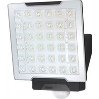
| Product type | LED wall light up/down lighting |
| Brand | Steinel |
| Model | L 910 LED |
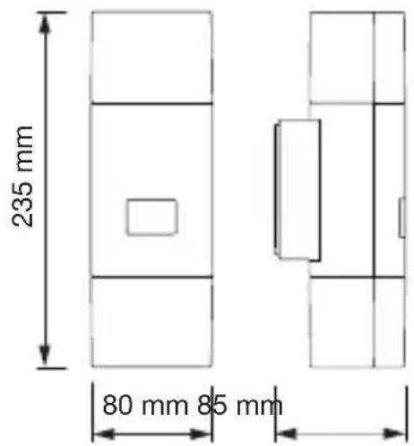
| Dimensions (H x W x D) | 235 x 80 x 85 mm |
| Weight | Approx. 0.5 kg (estimated) |
| Power supply | 220-240 V ~ 50/60 Hz |
| Power consumption | 9.80 W |
| Luminous flux | 797 lm |
| Luminous efficacy | 81 lm/W |
| Color temperature | 3000 K (warm white) |
| Color rendering index (CRI) | 82 |
| Average lifespan | > 60 000 h (L70B50 at 25°C) |
| Protection rating | IP44 |
| Protection class | II |
| Operating ambient temperature | -20 °C to +40 °C |
| Energy efficiency class | E |
| Light source | Integrated non-replaceable LED |
| Main functions | Up/down lighting, suitable for outdoor use (IP44) |
| Package contents | Wall light, wall bracket, 3 screws, 3 wall plugs, 3 spacer pieces, 2 locking screws |
| Maintenance and cleaning | Clean with a damp cloth; do not use detergent |
| Safety | Disconnect power before any intervention; installation according to NF C-15100 standard; repairs by a specialist workshop |
| Spare parts and repairability | Non-replaceable light source; use only original spare parts |
| Manufacturer warranty | 36 months (parts and labor) |
Frequently Asked Questions - L 910 LED STEINEL
User questions about L 910 LED STEINEL
0 question about this device. Answer the ones you know or ask your own.
Ask a new question about this device
Download the instructions for your Lighting in PDF format for free! Find your manual L 910 LED - STEINEL and take your electronic device back in hand. On this page are published all the documents necessary for the use of your device. L 910 LED by STEINEL.
USER MANUAL L 910 LED STEINEL
natural_image
World map silhouette in grayscale, showing continents and oceans without any text or labelsContact
www.steinel.de/contact

.steinel
L 910 S
L 910
L 930 S
L 930
DE....8
GB....14
FR....19
NL....25
IT .....30
ES....36
PT....42
SE....48
DK....53
FI....58
NO .....63
GR....68
TR....74
HU .....79
CZ....85
SK....90
PL .....96
RO .....102
SI....108
HR....113
EE....119
LT.....124
LV....129
RU .....134
BG .....140
CN....146
Textteil beachten!
Follow written instructions!
natural_image
Technical line drawing of a cylindrical industrial vessel with internal components and mounting holes (no text or symbols)3.4
L910
natural_image
Technical line drawing of a mechanical device with internal components and mounting holes (no text or symbols)3.2
L910
natural_image
Technical line drawing of a cylindrical mechanical component with internal components and mounting holes (no text or symbols)3.5
L 910 S L 910
3.3
L 930 S
natural_image
Technical line drawing of an electrical enclosure with internal components and mounting screws (no text or symbols)3.6
L 930 S L 910
3.7
3.9
L 910 S, L 930 S
3.10
L 910 S, L 910
radar
| Angle | Value | |-------|-------| | 0° | 100 | | 30° | 150 | | 60° | 120 | | 90° | 80 | | 120° | 180 | | 150° | 140 | | 180° | 160 |3.8
3.11
L 930 S, L 930
radar
| Angle | Value | |-------|-------| | 0° | 180 | | 30° | 150 | | 60° | 120 | | 90° | 90 | | 120° | 60 | | 150° | 40 | | 180° | 20 | | 210° | 40 | | 240° | 60 | | 270° | 90 | | 300° | 120 | | 330° | 150 | | 360° | 180 |
flowchart
graph TD
    A["ON"] --> B["BASIC LIGHT OFF"]
    A --> C["1/2 OFF"]
    A --> D["2lux 20lux"]
    A --> E["2min 15min"]
    A --> F["Test OFF"]
    A --> G["5m 12m"]
    style A fill:#f9f,stroke:#333
    style B fill:#ccf,stroke:#333
    style C fill:#cfc,stroke:#333
    style D fill:#fcc,stroke:#333
    style E fill:#cff,stroke:#333
    style F fill:#ffc,stroke:#333
    style G fill:#fcc,stroke:#333
DE
Please read carefully and keep in a safe place.
– Under copyright. Reproduction either in whole or in part only with our consent.
Symbols
Hazard warning!
2. General safety precautions

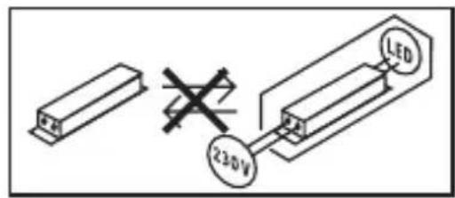
Disconnect the power supply before attempting any work on the unit.
- During installation, the electric power cable being connected must not be live.
Therefore, switch off the power first and use a voltage tester to make sure the wiring is off-circuit. - Installing the light involves work on the mains voltage supply. This work must therefore be carried out professionally in accordance with national wiring regulations and electrical operating conditions. (e.g. DE - VDE 0100, AT-ÖVE / ÖNORM E8001-1, CH- SEV 1000)
- Only use genuine replacement parts.
- Repairs may only be made by specialist workshops.
3. L 910 S, L 910, L 930 S, L 930
Proper use
L 910 S, L 930 S
- LED uplight / uplight-downlight with infrared sensor.
Proper use
L 910, L 930
- LED uplight / uplight-downlight.
L 910 S, L 930 S:
The integrated infrared sensor detects the invisible heat radiated from moving objects (people, animals, etc.).
The heat detected in this way is converted electronically into a signal that switches the light ON automatically. Heat is not detected through obstacles, such as walls or panes of glass, and will therefore not activate the light.
Twilight-controlled effect lighting on the wall can be selected as an option.
Important:
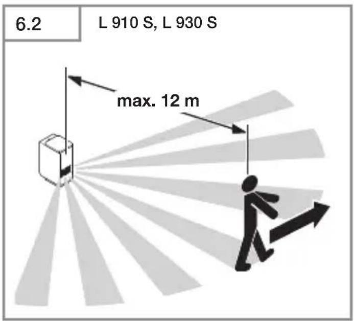
The most reliable way of detecting motion is to install the light with the sensor aimed across the direction in which a person would walk and by ensuring that no obstacles (such as trees and walls, for example) obstruct the line of sensor vision. Reach is limited when walking directly towards the light.
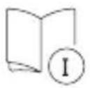
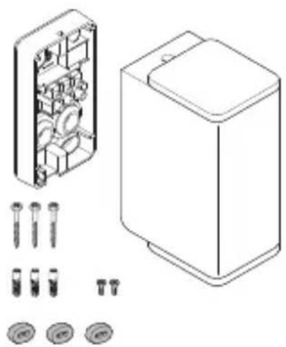
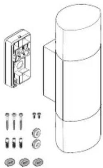
Package contents (Fig. 3.1/3.2/3.3/3.4)
- Light
- Wall mount
- Three screws
- Three wall plugs
- Three spacers
- Two retaining screws
Product dimensions L 910 S, L 910 (Fig. 3.5)
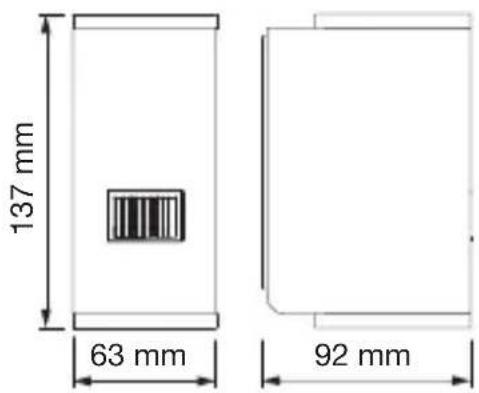
Product dimensions L 930 S, L 930 (Fig. 3.6)
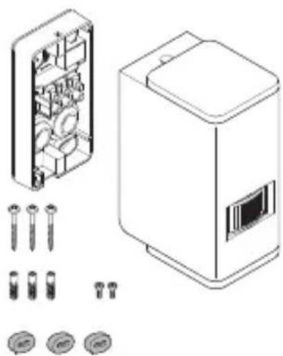
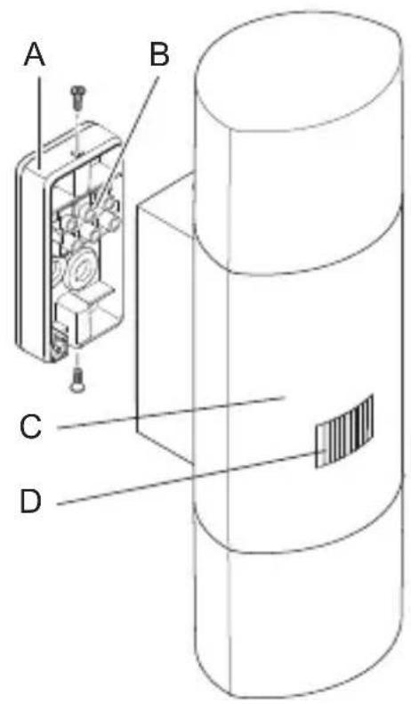
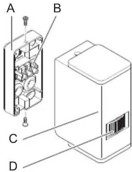
Product components (Fig. 3.7/3.8)
A Wall mount
B Connecting terminal
C Light enclosure
D IR sensor (L 910 S, L 930 S only)
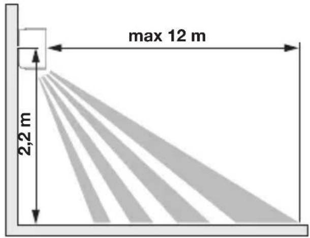
Detection zone (Fig. 3.9)
(L 910 S, L 930 S only)
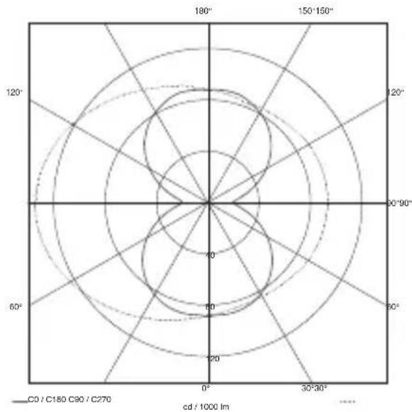
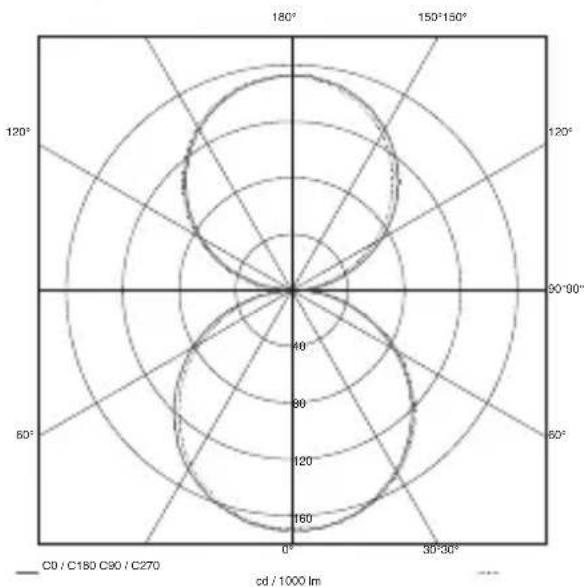
L 910 S, L 910 luminous intensity distribution
(Fig. 3.10)
L 930 S, L 930 luminous intensity distribution
(Fig. 3.11)
4. Electrical connection
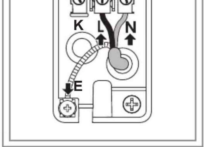
Wiring diagram (Fig. 4.1)
The supply lead is a three-core cable:
L = phase conductor (usually black, brown or grey)
N = neutral conductor (usually blue)
PE = protective-earth conductor (green/yellow)
K = communication cable (optional) (L 910 S, L 930 S only)
If you are in any doubt, identify the conductors using a voltage tester; then disconnect from the power supply again. Connect phase (L)
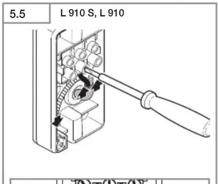
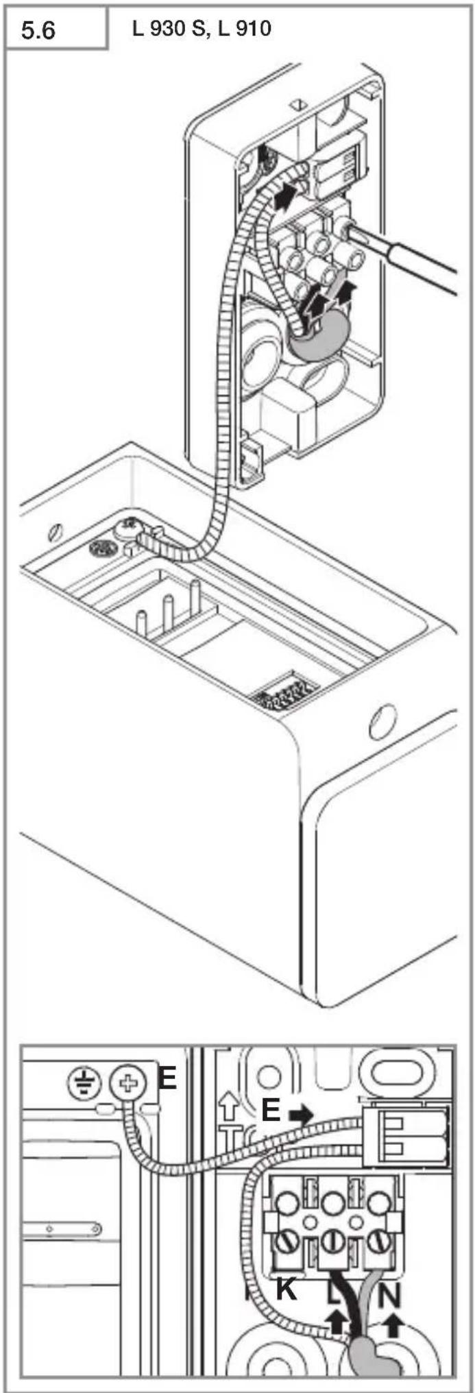
and neutral conductor (N) to the connecting terminal, connect protective-earth conductor
(PE) to terminal (E). (Fig. 5.5/5.6)
Important:
Incorrectly wired connections will produce a short circuit later on in the product or fuse box. In this case, you must identify the individual conductors once again and reconnect them. A mains switch for switching the product ON and OFF may, of course, be installed in the mains supply lead.
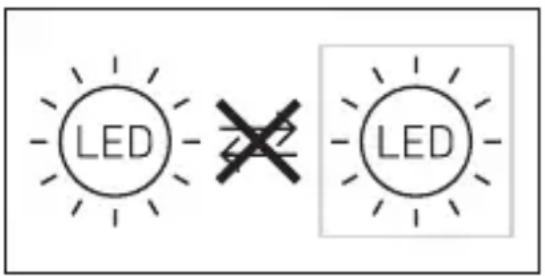
The light source of this luminaire cannot be replaced. If the light source needs to be replaced (e.g. at the end of its service life), the complete luminaire must be replaced.
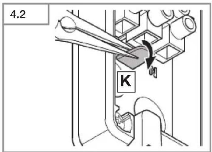
Group behaviour
Communication cable (K) permits internal STEINEL group interconnection of L 910 S, L 930 S.
For this, the cover tab in the terminal compartment must be broken off. (Fig. 4.2)
As many as 10 lights can be interconnected with each other. Maximum communication cable length is 50 m.
The first light in a group to detect movement switches the entire group ON. If no further movement is detected after the time setting selected, the last light in a group to detect movement switches the entire group OFF.
Note:
- No voltage may be connected to the communication cable. Do no connect any external loads.
– Within the interconnected group, all lights operate in line with their specific DIP-switch settings.
– Group interconnection is not possible in test mode.
5. Mounting
- Check all components for damage.
- Do not use the product if it is damaged.
- When installing the light, make sure the installation site is not subject to vibration.
- Select an appropriate mounting location, taking the reach and motion detection into consideration.
Mounting procedure
- Switch OFF power supply (Fig. 4.1)
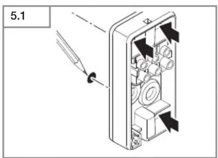
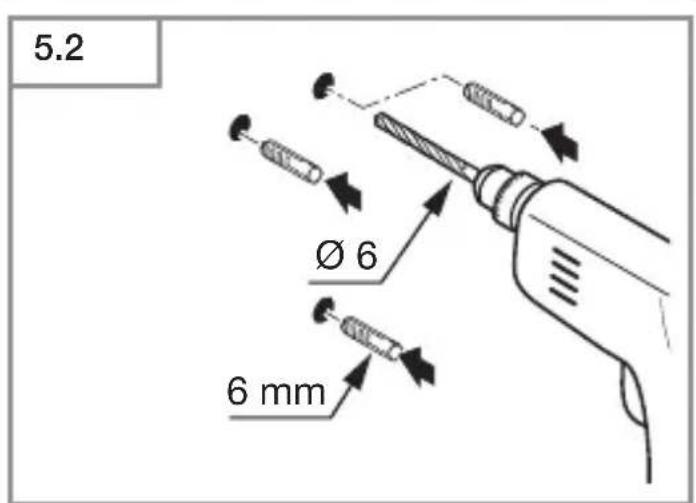
• Mark drill holes (Fig. 5.1) - Drill holes and insert wall plugs (Fig. 5.2)
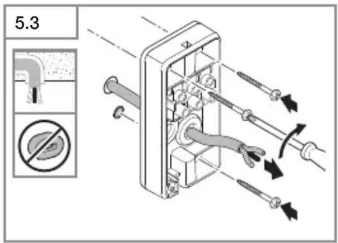
• Fit sealing plug (L 910 only) - Installation with concealed power supply lead (Fig. 5.3)
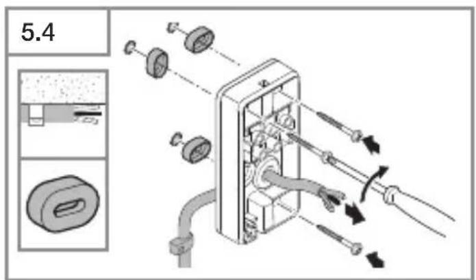
- Installation with surface-mounted power supply lead (Fig. 5.4)
- Connect conductors
- Connect protective earth conductor (PE) to terminal (E) (L 910 S, L 910) (Fig. 5.5)
- Connect power supply lead's protective earth conductor (PE) to WAGO terminal (L 930 S, L 930) (Fig. 5.6)
• Make settings → "6. Function"
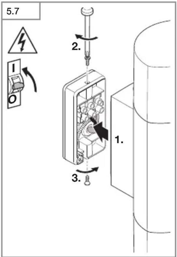
- Fit light enclosure and screw in place with retaining screw (Fig. 5.7)
Important:
Make sure light enclosure is screwed on firmly.
- Switch ON power supply (Fig. 5.7)
6. Function
Functions can be set for the L 910 S, L 930 S sensor versions.
Factory setting: all DIP switches OFF
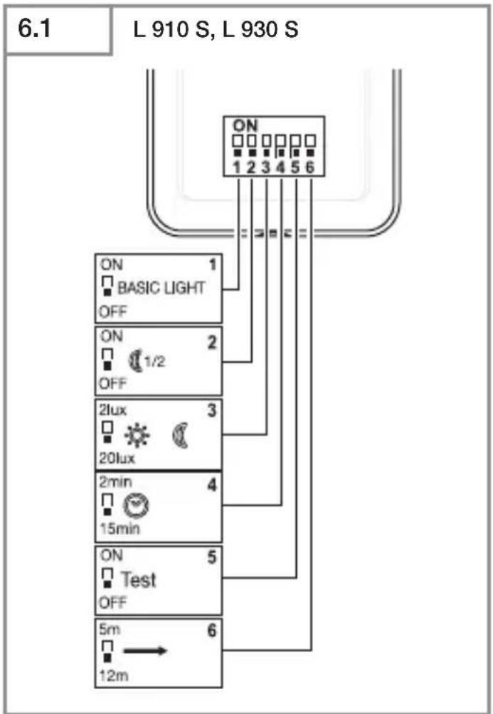
Once installed, the light can be put into operation. All pre-programmed functions are selected via DIP switches 1 to 6. (Fig. 6.1)
DIP 1: effect lighting
OFF = sensor mode, main light / soft start ON = effect lighting as from light-level setting selected, main light activated by sensor
DIP 2: night economy mode, effect lighting
OFF = effect lighting ON all night ON = effect lighting ON for half the night in relation to setting selected at DIP 1
DIP 3: twilight setting
OFF=20lux
ON=2lux
DIP 4: time setting
OFF=2minutes
ON=15minutes
DIP 5: test mode
OFF = test mode deactivated ON = test mode activated (5 seconds)
Note:
Communication (optional group interconnection) to the interconnected lights is deactivated in test mode. Only the light being tested is in test mode. The other lights remain in group mode. Delay time is 8 seconds. The light is in daytime mode. Manual override (4 h mode) cannot be selected in daytime mode.
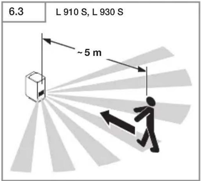
DIP 6: reach adjustment
OFF=12m(Fig. 6.2)
ON=5m(Fig. 6.3)
If a mains switch is installed in the mains supply lead, the following functions are available in addition to simply switching light ON and OFF:
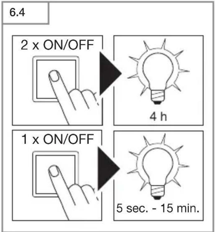
Manual override (Fig. 6.4)
1) Activate manual override:
Switch OFF and ON twice. The light is set to
manual override for 4 hours. Then it returns automatically to sensor mode.
2) Deactivate manual override:
Switch OFF and ON once. Light goes out or switches to sensor operation.
Important:
Switching must take place within 0.2 to 1 second.
Note:
When groups are interconnected, this command is sent to all of the lights that are connected.
7. Maintenance / care
The product requires no maintenance.
The light can be cleaned with a damp cloth (without detergents) if dirty.
Important note: the control gear cannot be replaced.
8. Disposal
Electrical and electronic equipment, accessories and packaging must be recycled in an environmentally compatible manner.
Do not dispose of electrical and electronic equipment as domestic waste.
For EU countries only:
under the current European Directive on Waste Electrical and Electronic Equipment and its transposition in national law, electrical and electronic equipment no longer suitable for use must be collected separately and recycled in an environmentally compatible manner.
9. Manufacturer's warranty
This STEINEL product has been manufactured with utmost care, tested for proper operation and safety and then subjected to random sample inspection. STEINEL guarantees that it is in perfect condition and proper working order. The warranty period is 36 months and starts on the date of sale to the consumer. We will remedy defects caused by material flaws or manufacturing faults. The warranty will be met by repair or replacement of defective parts at our own discretion. The warranty shall not cover damage to wear parts, damage or defects caused by improper treatment or maintenance. Further consequential damage to other objects shall be excluded.
Claims under the warranty will only be accepted if the unit is sent fully assembled and well-packed with a brief description of the fault, a receipt or invoice (date of purchase and dealer's stamp) to the appropriate Service Centre.
Repair service:
If defects occur outside the warranty period or are not covered by the warranty, ask your nearest service station for the possibility of repair.
GB
- Technical Specifications
| Dimensions (H × W × D) | L 910 S, L 910: 235 × 80 × 85 mmL 930 S, L 930: 137 × 63 × 92 mm | |
| Power supply 220 - 240 V, 50 / 60 Hz | ||
| Power consumption ( P_on ) L 910 S, L 910: 9.80 WL 930 S, L 930: 9.30 W | ||
| Light output L 910 S, L 910: 797 lmL 930 S, L 930: 457 lm | ||
| Efficiency L 910 S, L 910: 81 lm/WL 930 S, L 930: 49 lm/W | ||
| Standby sensor ( P_sb ) 0.30 W | ||
| Colour temperature 3,000 K (warm white) | ||
| Colour rendering index R | _a = 82 | |
| Average rated life expectancy L70B50 at 25°C: >60,000 hours | ||
| Colour consistency SDCM Starting value: 3 | ||
| Luminous intensity distribution L 910 | L 930 | |
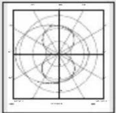 | 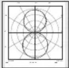 | |
| Detection reach | L 910 S, L 930 S: 12 m | |
| Angle of coverage L 910 S: 180° | L 930 S: 140° | |
| Time setting L 910 S, L 930 S: 120 sec. - 15 min. | ||
| Twilight setting L 910 S, L 930 S: 2 - 20 lux | ||
| Effect light L 910 S, L 930 S: optionally via DIP switch | ||
| Lamp LED | ||
| IP rating IP 44 | ||
| Protection class L 910 S, L 910: II | L 930 S, L 930: I | |
| Ambient temperature -20°C to +40°C | ||
| Energy efficiency class L 910 S, L 910 contain an energy class "E"light source.L 930 S, L 930 contain an energy efficiency class "D" light source. | ||
11. Troubleshooting
Malfunction Cause Remedy
| Light without power ■ Fuse has tripped, not switched ON, break in wiring■ Short circuit in mains power supply lead■ Any mains switch OFF | ■ Activate, change fuse, turn ON mains switch, check wiring with voltage tester■ Check connections■ Switch on mains switch |
| Light does not switch ON ■ Wrong twilight setting selected■ Mains switch OFF■ Fuse has tripped | ■ Reset■ Switch ON■ Activate, change fuse, check connection if necessary |
| Light does not switch OFF ■ Continued movement within the detection zone | ■ Check detection zone |
| Light does not switch OFF completely ■ Basic light level selected | ■ Check DIP 1 and DIP 2 |
| Light switching ON despite no movement being detected ■ Light not mounted for detecting movement reliably■ Movement occurred but not identified by the observer (movement behind wall, small object moving in immediate proximity of lamp etc.) | ■ Securely mount enclosure■ Check detection zone |
FR
- Led-lamp Uplight-/Up-Downlight.
L 910 S, L 930 S:
– Lampada LED uplight-/up-downlight.
L 910 S, L 930 S:
(solo L 910 S, L 930 S)
(solo L 910 S, L 930 S)
- LED-lampe Uplight/Up-Downlight.
L 910 S, L 930 S:
- LED-lampe uplight-/up-downlight.
L 910 S, L 930 S:
Den integrerte infrarødsensoren registrerer den usynlige varmestrålingen fra f.eks. mennesker eller dyr som beveger seg. Den registrerte varmestrålingen omsettes elektronisk og tenner
DIP 6: Rekkeviddeinnstilling
OFF=12m(ill. 6.2)
ON=5m(ill. 6.3)
Permanent lys (ill. 6.4)
1) Tenne permanent lys:
8. Απόσυρση
- LED Iamba Uplight-/Up-Downlight.
L 910 S, L 930 S:
– Svítidlo LED Uplight-/Up-Downlight.
L 910 S, L 930 S:
ZAP = 5 m (obr. 6.3)
OFF = 12 m (obr. 6.2) ON = 5 m (obr. 6.3)
- Lampa LED Uplight /Up-Downlight.
L 910 S, L 930 S:
3 ANI GARANTIA PRODUCATORULUI
IZKLOP (OFF) = 20 luksov
VKLOP (ON) = 2 luksa
IZKLOP (OFF) = 12 m (sl. 6.2)
VKLOP (ON) = 5 m (sl. 6.3)
OFF = 12 m (joon. 6.2)
ON = 5 m (joon. 6.3)
(camo L 910 S, L 930 S)
小组特征
OFF = 20 Lux ON = 2 Lux
DIP 4: 时间设置
8. 废弃物处理

- Contact
- .steinel
- DE
- Please read carefully and keep in a safe place.
- Symbols
- General safety precautions
- Disconnect the power supply before attempting any work on the unit.
- L 910 S, L 910, L 930 S, L 930
- Proper use
- L 910 S, L 930 S:
- Important:
- Package contents (Fig. 3.1/3.2/3.3/3.4)
- Product components (Fig. 3.7/3.8)
- (Fig. 3.10)
- (Fig. 3.11)
- Electrical connection
- Wiring diagram (Fig. 4.1)
- Group behaviour
- Note:
- Mounting
- Mounting procedure
- Function
- Factory setting: all DIP switches OFF
- DIP 1: effect lighting
- DIP 2: night economy mode, effect lighting
- DIP 3: twilight setting
- DIP 4: time setting
- DIP 5: test mode
- DIP 6: reach adjustment
- Manual override (Fig. 6.4)
- 1) Activate manual override:
- 2) Deactivate manual override:
- Maintenance / care
- Disposal
- For EU countries only:
- Manufacturer's warranty
- Repair service:
- Troubleshooting
- FR
- DIP 6: Rekkeviddeinnstilling
- Permanent lys (ill. 6.4)
- 1) Tenne permanent lys:
- Απόσυρση
- ANI GARANTIA PRODUCATORULUI
- DIP 4: 时间设置
- 废弃物处理
Brand : STEINEL
Model : L 910 LED
Category : Lighting