DL 750 - Lighting STEINEL - Free user manual and instructions
Find the device manual for free DL 750 STEINEL in PDF.
User questions about DL 750 STEINEL
0 question about this device. Answer the ones you know or ask your own.
Ask a new question about this device
Download the instructions for your Lighting in PDF format for free! Find your manual DL 750 - STEINEL and take your electronic device back in hand. On this page are published all the documents necessary for the use of your device. DL 750 by STEINEL.
USER MANUAL DL 750 STEINEL
Unit 714, Northwest Business Park · Kilshane Drive
Ballycoolin · Dublin 15 · Tel.: +353/1/8809120
Fax: +353/1/8612061 · info@sockettool.ie
F DUVAUCHEL S.A.
ACTICENTRE - CRT 2
Tel: +421/42/4 45 67 10 - Fax: +421/42/4 45 67 11
neco@neco.sk · www.neco.sk
no Steinel Distribution SRL
Parc industrial Metrom - RO - 500269 Brasov
Str. Carpatilor nr. 60
Tel: +40/01268 53 00 00 · Fax: +40/01268 53 11 11
www.steinel.ro
(Dalinsko Upravljanje d.o.o.
B. Smelane 10 · HR-10 000 Zagreb
Tel: +3 85/1/3 88 02 47 Fax: +3 85/1/3 88 02 47
dalinsko-uprav|anie@inet.hr
LMAmberos SIA
Brivbas calye 195-16 - LV-1039 Riga
Tel: 00371 67550740 - Fax: 00371 67552850
www.ambergs.lv
© Производитель
natural_image
Close-up of a white ceiling light fixture with a circular recess and radial base, no visible text or symbols.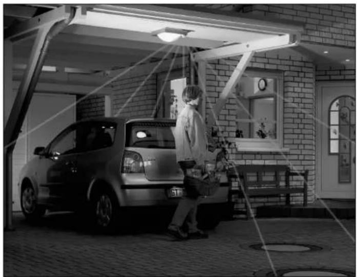
natural_image
Black-and-white photo of a person standing beside a car under a shelter, with no visible text or symbols.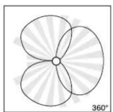
natural_image
Symmetrical four-petal flower-like shape with radiating petals, no text or symbols present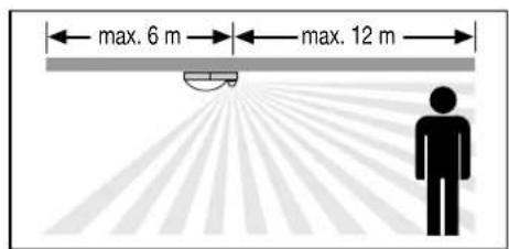
text_image
max. 6 m max. 12 m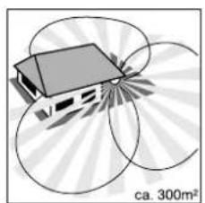
natural_image
Diagram of a house with solar panels surrounding a 300m² scale, no text or symbols present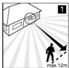
text_image
1 max.12m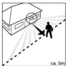
natural_image
Illustration of a person using a tool to spray or spray near a house, with a dashed line indicating distance (no text or symbols)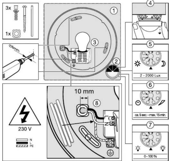
text_image
3x 1x Ø6mm 10 mm 230 V N L PE ① ③ ② ④ ⑤ 2 - 2000 Lux ⑥ ca. 5 sec. - max. 15 min. ⑦ 0 - 100 %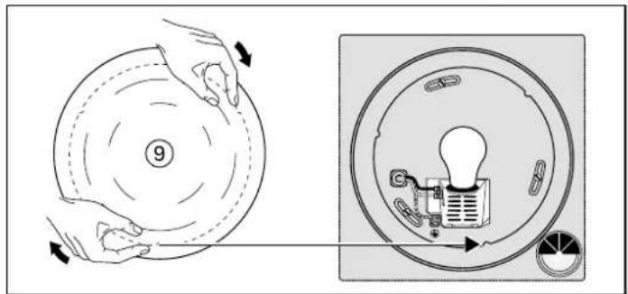
text_image
Diagram illustrating a device operation with labeled parts and directional arrows, showing hand positioning and internal components.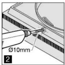
text_image
Ø10mm 2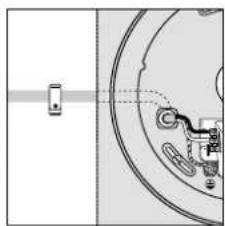
natural_image
Pure mechanical diagram showing a shaft and gear assembly without any text or symbols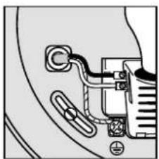
natural_image
Pure electrical circuit lines without any symbols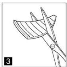
natural_image
Line drawing of a pair of scissors cutting a blade, no text or symbols present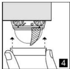
natural_image
Diagram of a hand pressing down on a cup with arrows indicating motion (no text or symbols)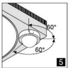
text_image
60° 60° 5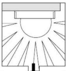
natural_image
Diagram of a sunlit indoor structure with rays radiating from a central point (no text or symbols)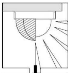
natural_image
Pure technical diagram showing a cross-section with shaded region and radiating lines, no text or symbols present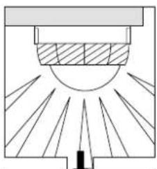
natural_image
Pure diagram of a sunlit indoor structure with rays, no text or symbols present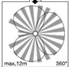
natural_image
Diagram of a four-blade fan-like structure with radial blades and central hub, labeled max.12m and 360° (no text or symbols beyond labels)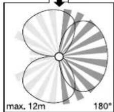
natural_image
Diagram of a four-petal flower with radial blades and a central hub, labeled with maximum 12m width and 180° angle (no text or symbols beyond labels)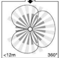
natural_image
Symmetrical abstract diagram with four petal-like shapes and radial lines, labeled with radius <12m and 360° (no text or symbols within the diagram itself)Tipp!
  lalogen lalogen | normal/not dimmable | dimmable(all dimmers) | |
| [S0034] | [SW7H] | ||
 |  |  min. 5 min. min. 5 min. | [STK0]min. 5 min. |
 |  |  Watt-o- Watt-o- |  |
 |  |  | 10% - 100% |

Montageanleitung
GB Installation instructions
Dear customer,
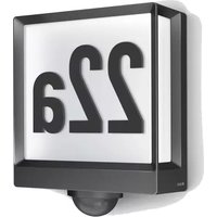
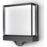
Congratulations on purchasing your new STEINEL Ceiling-SensorLight and thank you for the confidence you have shown in us. You have chosen a high-quality product that has been manufactured, tested and packed with the greatest care.
Please familiarise yourself with these instructions before attempting to install the CeilingSensorLight as prolonged reliable and trouble-free operation will only be ensured if it is fitted correctly.
We hope your new Ceiling-SensorLight will give you lasting satisfaction.
System components
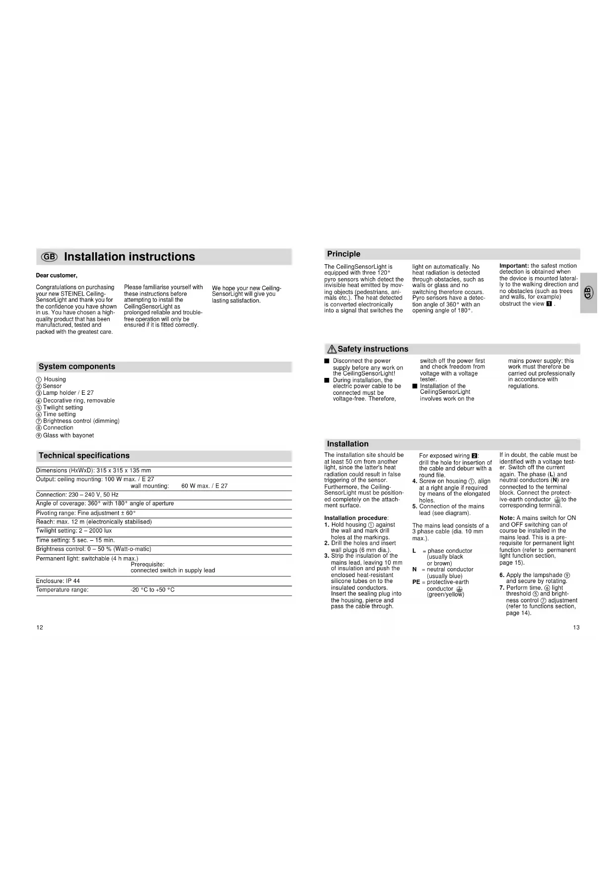
① Housing
② Sensor
③ Lamp holder / E 27
④ Decorative ring, removable
⑤ Twilight setting
⑥ Time setting
⑦ Brightness control (dimming)
① Connection
⑨ Glass with bayonet
Technical specifications
| Dimensions (HxWxD): 315 x 315 x 135 mm |
| Output: ceiling mounting: 100 W max. / E 27 |
| wall mounting: | 60 W max. / E 27 |
| Connection: 230 – 240 V, 50 Hz |
| Angle of coverage: 360° with 180° angle of aperture |
| Pivoting range: Fine adjustment ± 60° |
| Reach: max. 12 m (electronically stabilised) |
| Twilight setting: 2 – 2000 lux |
| Time setting: 5 sec. – 15 min. |
| Brightness control: 0 – 50 % (Watt-o-matic) |
| Permanent light: switchable (4 h max.) |
| Prerequisite: |
| connected switch in supply lead |
| Enclosure: IP 44 |
| Temperature range: |
| -20 °C to +50 °C |
Principle
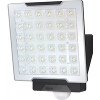
The CeilingSensorLight is equipped with three 120° pyro sensors which detect the invisible heat emitted by moving objects (pedestrians, animals etc.). The heat detected is converted electronically into a signal that switches the
light on automatically. No heat radiation is detected through obstacles, such as walls or glass and no switching therefore occurs. Pyro sensors have a detection angle of 360° with an opening angle of 180°.
Important: the safest motion detection is obtained when the device is mounted laterally to the walking direction and no obstacles (such as trees and walls, for example) obstruct the view 1.
⚠ Safety instructions
■ Disconnect the power supply before any work on the CeilingSensorLight!
■ During installation, the electric power cable to be connected must be voltage-free. Therefore,
switch off the power first and check freedom from voltage with a voltage tester.
■ Installation of the CeilingSensorLight involves work on the
mains power supply; this work must therefore be carried out professionally in accordance with regulations.
Installation
The installation site should be at least 50 cm from another light, since the latter's heat radiation could result in false triggering of the sensor. Furthermore, the Ceiling-SensorLight must be positioned completely on the attachment surface.
Installation procedure:
- Hold housing ① against the wall and mark drill holes at the markings.
- Drill the holes and insert wall plugs (6 mm dia.).
- Strip the insulation of the mains lead, leaving 10 mm of insulation and push the enclosed heat-resistant silicone tubes on to the insulated conductors. Insert the sealing plug into the housing, pierce and pass the cable through.
For exposed wiring 2: drill the hole for insertion of the cable and deburr with a round file.
4. Screw on housing ①, align at a right angle if required by means of the elongated holes.
5. Connection of the mains lead (see diagram).
The mains lead consists of a 3 phase cable (dia. 10 mm max.).
L = phase conductor (usually black or brown)
N = neutral conductor (usually blue)
PE = protective-earth
conductor ⊕
(green/yellow)
If in doubt, the cable must be identified with a voltage tester. Switch off the current again. The phase (L) and neutral conductors (N) are connected to the terminal block. Connect the protective-earth conductor ⊖ to the corresponding terminal.
Note: A mains switch for ON and OFF switching can of course be installed in the mains lead. This is a prerequisite for permanent light function (refer to permanent light function section, page 15).
-
Apply the lampshade ⑨ and secure by rotating.
-
Perform time, ⑥ light threshold ⑤ and brightness control ⑦ adjustment (refer to functions section, page 14).
Functions
Once you have installed the housing and connected the CeilingSensorLight, it can be
put into operation. After removing the decorative ring ④ the adjusting screws for
twilight, time and brightness control are visible.
text_image
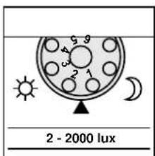
2 - 2000 luxTwilight setting (threshold) ⑤
text_image
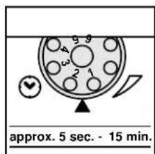
approx. 5 sec. - 15 min.Switch-off delay (time setting) ⑥
text_image
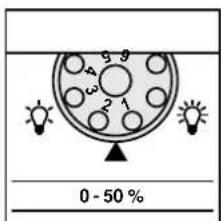
0 - 50 %Brightness control (Watt-o-matic) ⑦
Continuously adjustable sensor response threshold from 2 - 2000 lux.
Adjustment control set to 1 = daylight operation, approx. 2000 lux. (factory setting)
Adjustment control set to 6 = night-time operation approx. 2 lux.
The adjustment control must be set to 1 (daylight operation) when setting the detection zone in daylight.
Continuously adjustable light duration of 5 sec. to 15 min.
Adjustment control set to 1 = shortest time (5 sec., factory setting)
Adjustment control set to 6 = longest time (15 min.)
When setting the detection zone, it is recommended to select the shortest time (setting 1).
Continuously adjustable constant light from 0 - 50 %. When movement is detected, the light switches from, say, 20 watts maintained light output to maximum output (100 watts).
Adjustment control set to 1 = no dimming (factory setting)
Adjustment control set to 6 = greatest dimming
If this control is rotated, the red LED (behind the lens) flashes and the light illuminates with the set brightness. After release, the dimming level can be further adjusted for approx. 3 sec. (LED continues to flash).
Soft light illumination
The CeilingSensorLight has a soft light illumination function. This means that the light does not switch directly to full
output when switched on, but the brightness is slowly increased to 100% within two seconds. The electronics
operate equally gently when switching off.
Permanent light function
If a power switch is installed in the supply lead, the following functions are
possible in addition to simply switching ON and OFF:
Important:
The switch should be operated repeatedly in short succession (in the range of 0.5 - 1 sec.)
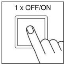
text_image
1 x OFF/ON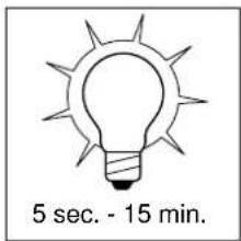
text_image
5 sec. - 15 min.Sensor operation
1) Switch on the light: Switch 1 x OFF and ON The light remains on for the set time.
2) Switch off light:
Switch 1 x OFF and ON The light goes out or transfers to sensor operation.
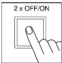
text_image
2 x OFF/ON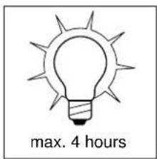
text_image
max. 4 hoursPermanent light operation
1) Switch on the light: Switch 2 x OFF and ON The light is set to permanent illumination for 4 hours (the red LED illuminates behind the lens). It subsequently changes automatically to sensor operation (red LED goes out).
2) Switch off light:
Switch 1 x OFF and ON The light goes out or changes to sensor operation.
Reach setting/adjustment
Assuming an installation height of 2.5 m, the maximum reach of the sensor is 12 m. Optimum adjustment of the detection zone is possible according to needs. The shrouds provided serve to cover any desired number of lens segments and individually reduce the reach. False switching by cars and
pedestrians, etc. is therefore ruled out, or risk areas deliberately monitored. The shrouds can be divided vertically or horizontally along the grooved divisions, or cut with scissors 3. After removing the decorative ring 4, the shrouds are to be suspended on the upper part of the sensor lens.
The decorative ring is subsequently to be reapplied and the shrouds are fixed firmly in place.
Fine adjustment is also possible by turning the sensor housing by ± 60° 5
Troubleshooting
| Malfunction | Cause | Remedy |
| CeilingSensorLight without power | ■ Fuse has blown; not switched ON; break in wiring■ Short circuit■ Mains switch OFF | ■ Replace fuse, switch on mains switch, check wiring with voltage tester■ Check connections■ Switch power ON |
| CeilingSensorLight does not switch on | ■ Twilight setting in nighttime mode during daytime operation■ Bulb burnt out■ Mains switch OFF■ House fuse faulty■ Detection zone not correctly adjusted■ Product's internal electrical fuse has been activated (LED illuminates permanently) | ■ Readjust (control 5)■ Replace light bulb■ Switch power on■ New house fuse, check connection if necessary■ Readjust■ Switch off, eliminate short circuit if appropriate and switch on again |
| CeilingSensorLight does not switch off | ■ Continued movement within the detection zone■ Dimming set to 50 % | ■ Check detection zone and readjust if necessary■ Readjust dimming |
| CeilingSensorLight switches on when it should not | ■ Wind is moving trees and bushes in the detection zone■ Cars in the street are detected■ Sunlight shining on the lens■ Sudden temperature changes due to weather (wind, rain, snow) or exhaust air from fans or open windows | ■ Adjust zone■ Adjust zone■ Mount sensor in a protected place or change detection zone■ Adjust detection zone or install in a different place |
| CeilingSensorLight reach modification | ■ Differing ambient temperatures | ■ Use shrouds to define detection zone precisely |
| Red LED is constantly illuminated, even without no permanent light setting | ■ Product's internal electrical fuse has been activated■ Bulb burnt out■ Bulb with more than 100 W connected | ■ Switch off, eliminate short circuit if appropriate and switch on again■ Change bulb■ Switch off SensorLight, insert a bulb with max. 100 W and switch on again |
Operation/Maintenance
| The CeilingSensorLight is suitable for switching on a light automatically. Weather can affect operation of the sensor. Strong gusts of wind, | snow, rain and hail can cause switching errors, since the sudden temperature changes cannot be distinguished from heat sources. The detection | lens can be cleaned with a damp cloth (without detergents) if dirty. |
CE Declaration of conformity
This product complies with the European Directive on Low-Voltage Appliances,
06/95/EC and the EMC Directive 04/108/EC.
Functional Warranty
This Steinel product has been manufactured with utmost care, tested for proper operation and safety and then subjected to random sample inspection. STEINEL guarantees that it is in perfect condition and proper working order. The warranty period is 36 months and starts on the date of sale to the consumer.
We will remedy defects caused by material flaws or manufacturing faults. The warranty will be met by repair or replacement at our own discretion. The warranty does not cover damage to wear parts or damage and defects caused by improper treatment, maintenance or the use of non-genuine parts. Further consequential damage to other objects is excluded. Claims under the warranty will only be accepted if the unit is sent fully assembled and well packed with a brief description of the fault, a
receipt or invoice (date of purchase and dealer's stamp) to the appropriate Service Centre.
Repair Service: Our Customer Service Department will repair faults not covered by warranty or after the warranty period. Please send the product well packed to your nearest Service Centre.

PE = aardedraad (groen/geel)