GL 60 LED - Lighting STEINEL - Free user manual and instructions
Find the device manual for free GL 60 LED STEINEL in PDF.
| Product type | Outdoor detector luminaire |
| Brand | Steinel |
| Model | GL 60 LED |
| Dimensions (H x Ø) | 1038 x 120 (glass) / 220 (base) mm |
| Weight | Approx. 1.5 kg |
| Power supply | 220-240 V / 50-60 Hz |
| Power consumption | 9.2 W (detection mode) / 0.8 W (standby) |
| Luminous flux | 954 lm (source supplied) / 781 lm (luminaire) |
| Luminous efficacy | 104 lm/W (source) |
| Color temperature | 3000 K (warm white) |
| Color rendering index | Ra = 82 |
| Average lifespan | L70B50 at 25°C: > 20,000 h |
| Detection angle | 360° (30° opening) |
| Detector range | Max. 12 m |
| Twilight threshold setting | 2 to 2000 lux (continuously adjustable) |
| Time delay | 5 seconds to 15 minutes (adjustable) |
| Orientation light | 0-50% of nominal power |
| Protection rating | IP44 |
| Protection class | II |
| Ambient temperature | -20 °C to +40 °C |
| Main functions | Infrared motion detection, forced ON 4h, orientation light, soft start |
| Care and cleaning | Clean the lens with a damp cloth, without detergent |
| Safety | Installation by a professional, cut power before intervention |
| Spare parts and repairability | Light source replaceable by user; manufacturer warranty 3 years, after-sales service |
| General information | Outdoor use, energy efficiency class F (supplied source) |
Frequently Asked Questions - GL 60 LED STEINEL
User questions about GL 60 LED STEINEL
0 question about this device. Answer the ones you know or ask your own.
Ask a new question about this device
Download the instructions for your Lighting in PDF format for free! Find your manual GL 60 LED - STEINEL and take your electronic device back in hand. On this page are published all the documents necessary for the use of your device. GL 60 LED by STEINEL.
USER MANUAL GL 60 LED STEINEL
natural_image
Close-up of a metallic cylindrical object with a handle and vertical slot, no visible text or symbols.GL 60 S
text_image
N L ⊕ 230 V ⑦ 2 - 2000 Lux ⑧ 5 sec.-15 min ⑨ 10 - 50% ⑥ ④ ③ ① ② ③. ⑤ L N + 20 cm 80mm/3,15" 9-10mm/0,37" ① ② ③. ④ ⑤ ⑥ 6x70 mm M6 x 20 8 mm⑪
natural_image
Symmetrical four-petal flower-like shape with radiating lines, labeled max. 12 m and 360° (no text or symbols on the flower itself)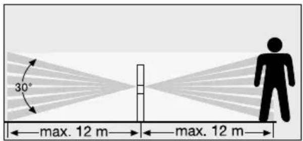
text_image
30° max. 12 m max. 12 m
natural_image
Radial graphic with a vertical line and a person silhouette, no text or symbols present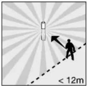
text_image
< 12m⑫
natural_image
Illustration of hands using a handheld device to interact with a keyboard (no text or symbols visible)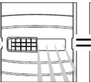
natural_image
Diagram of airflow or heat transfer through a container with a grid inside, showing parallel lines and a equality symbol (no text or labels)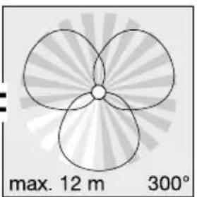
natural_image
Symmetrical four-petal flower-like shape with radial gradient background, labeled 'max. 12 m 300°' (no other text or symbols)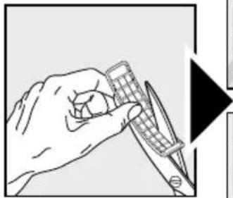
natural_image
Illustration of a hand holding a calculator and a pen, with no visible text or symbols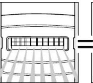
natural_image
Diagram of a vehicle rearview system with grid lines and a horizontal bar (no text or symbols)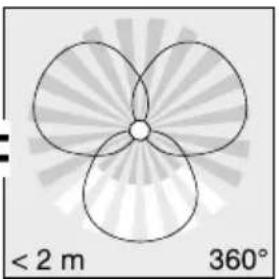
natural_image
Symmetrical geometric pattern with three petal-like shapes radiating from a central point, labeled with radius <2 m and 360° (no text or symbols beyond labels)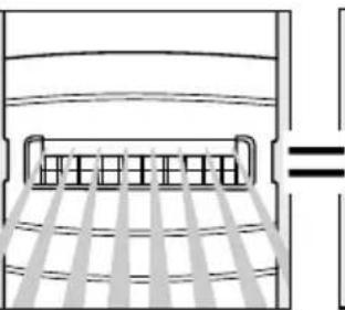
natural_image
Pure diagram of a bed with horizontal bars and diagonal lines, no text or symbols present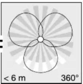
natural_image
Symmetrical abstract diagram with three petal-like shapes radiating from a central point, labeled with radius '360°' and distance '< 6 m' (no text or symbols within the diagram itself)⑬
text_image
1 x 5 sec.-15 min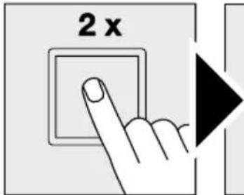
text_image
2 x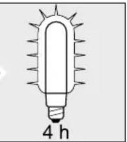
natural_image
Simple line drawing of a glowing incandescent light bulb with 4 hours label (no text or symbols on the bulb itself)DE Montageanleitung
text_image
Weather icon decomposition diagram showing sun and moon symbols with directional arrows and a checkmarkGB Installation instructions
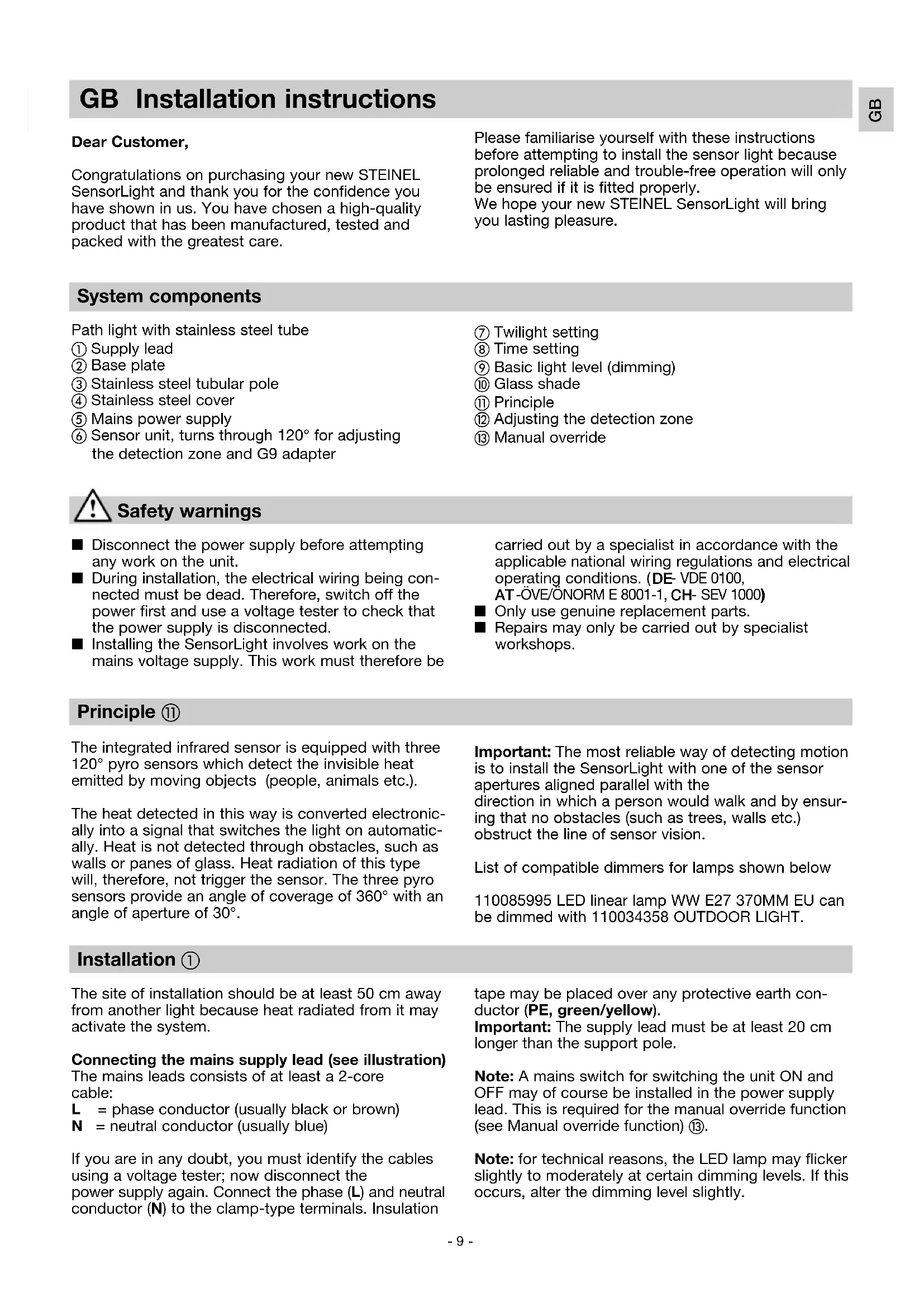
Dear Customer,
Congratulations on purchasing your new STEINEL SensorLight and thank you for the confidence you have shown in us. You have chosen a high-quality product that has been manufactured, tested and packed with the greatest care.
Please familiarise yourself with these instructions before attempting to install the sensor light because prolonged reliable and trouble-free operation will only be ensured if it is fitted properly.
We hope your new STEINEL SensorLight will bring you lasting pleasure.
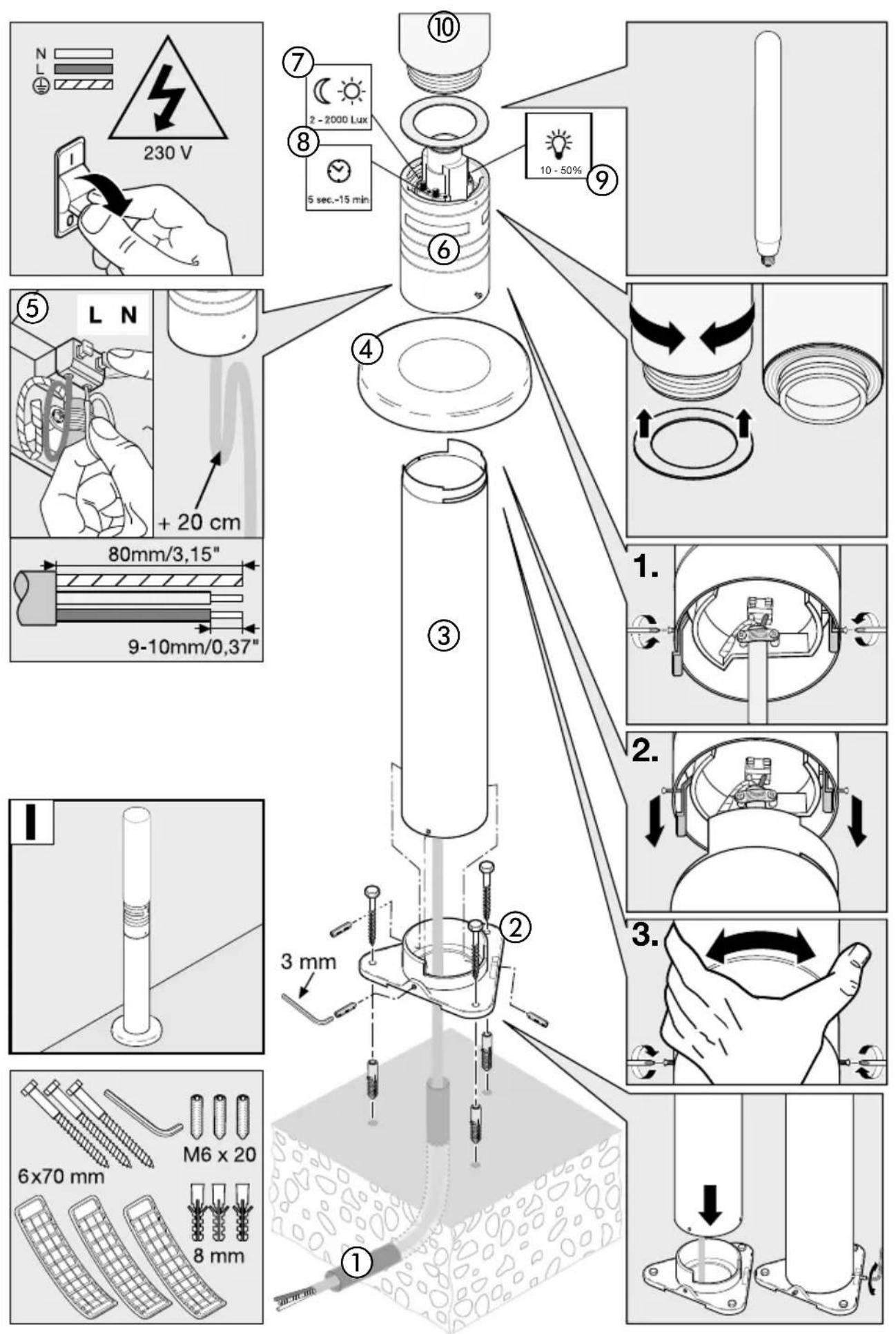
System components
Path light with stainless steel tube
① Supply lead
② Base plate
③ Stainless steel tubular pole
④ Stainless steel cover
⑤ Mains power supply
⑥ Sensor unit, turns through 120^ for adjusting the detection zone and G9 adapter
⑦ Twilight setting
⑧ Time setting
⑨ Basic light level (dimming)
⑩ Glass shade
⑪ Principle
⑫ Adjusting the detection zone
⑬ Manual override

Safety warnings
■ Disconnect the power supply before attempting any work on the unit.
■ During installation, the electrical wiring being connected must be dead. Therefore, switch off the power first and use a voltage tester to check that the power supply is disconnected.
■ Installing the SensorLight involves work on the mains voltage supply. This work must therefore be
carried out by a specialist in accordance with the applicable national wiring regulations and electrical operating conditions. (DE- VDE 0100, AT-ÖVE/ÖNORM E 8001-1, CH- SEV 1000)
■ Only use genuine replacement parts.
■ Repairs may only be carried out by specialist workshops.
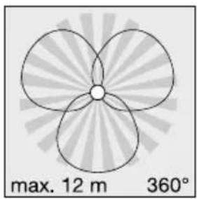
Principle ⑪
The integrated infrared sensor is equipped with three 120^ pyro sensors which detect the invisible heat emitted by moving objects (people, animals etc.).
The heat detected in this way is converted electronically into a signal that switches the light on automatically. Heat is not detected through obstacles, such as walls or panes of glass. Heat radiation of this type will, therefore, not trigger the sensor. The three pyro sensors provide an angle of coverage of 360^ with an angle of aperture of 30^ .
Important: The most reliable way of detecting motion is to install the SensorLight with one of the sensor apertures aligned parallel with the direction in which a person would walk and by ensuring that no obstacles (such as trees, walls etc.) obstruct the line of sensor vision.
List of compatible dimmers for lamps shown below
110085995 LED linear lamp WW E27 370MM EU can be dimmed with 110034358 OUTDOOR LIGHT.
Installation ①
The site of installation should be at least 50 cm away from another light because heat radiated from it may activate the system.
Connecting the mains supply lead (see illustration)
The mains leads consists of at least a 2-core cable:
L = phase conductor (usually black or brown)
N = neutral conductor (usually blue)
If you are in any doubt, you must identify the cables using a voltage tester; now disconnect the power supply again. Connect the phase (L) and neutral conductor (N) to the clamp-type terminals. Insulation
tape may be placed over any protective earth conductor (PE, green/yellow).
Important: The supply lead must be at least 20 cm longer than the support pole.
Note: A mains switch for switching the unit ON and OFF may of course be installed in the power supply lead. This is required for the manual override function (see Manual override function) ⑬.
Note: for technical reasons, the LED lamp may flicker slightly to moderately at certain dimming levels. If this occurs, alter the dimming level slightly.
Technical specifications
| Dimensions (H x ∅): | 1038 x ∅ 120 (glass shade) / ∅ 220 (base) mm |
| Power supply: | 220-240 V / 50/60 Hz |
| Power consumption (Pon)*: | 9.2 W / E 27 |
| Luminous flux/efficiency, lamp*: | 954 lm, 104 lm/W |
| Standby light: | 0.8 W |
| Luminous flux/efficiency: | 781 lm, 79.9 lm/W |
| Colour temperature*: | 3000 K (warm white) |
| Colour rendering index*: | Ra = 82 |
| Average rated life expectancy*: | L70B50 at 25°C: >20,000 hours. |
| Colour consistency SDCM*: | starting value: 3 |
| Luminous intensity distribution*: | 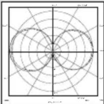 |
| Angle of coverage: | 360° with 30° angle of aperture |
| Detection reach: | Max. 12 m |
| Twilight setting: | 2-2000 lux |
| Time setting: | 5 s - 15 min |
| Manual override: | Selectable (4 hours) provided:switch is connected in mains supply lead |
| Basic light level: | 10-50% |
| IP rating: | IP44 |
| Protection class: | II |
| Ambient temperature: | -20°C to +40°C |
| This product contains an energy efficiency class "F" light source. | |
| * for LED lamp provided with the light | |
Functions ⑦, ⑧, ⑨
The sensor-switched light can be put into service after mounting the sensor unit and connecting it to the mains power supply. The controls for adjusting
the twilight response threshold, time and basic light level are positioned next to the lamp socket.
Twilight setting (response threshold) ⑦
(factory setting: daylight operation 2000 lux)
2 - 2000 Lux
Sensor response threshold can be infinitely varied from 2-2000 lux.
Control dial set to ⚙ = daylight operation approx. 2000 lux.
Control dial set to = twilight operation approx. 2 lux. To adjust the detection zone in daylight, set control dial to (daylight operation).
Switch-off delay (time setting) ⑧
(factory setting: 5 sec.)

5 sec.-15 min
Light ON duration can be infinitely varied from 5 sec. to 15 min.
Control dial set to - = shortest time
Control dial set to + = longest time (15 min.)
It is recommended to select the shortest time – when adjusting the detection zone
Basic light level ⑨
(factory setting: dimmer off: 0%)

0 - 50%
Light output can be infinitely adjusted up to 50 % of maximum power when set to stay ON all the time.
This means: light is only switched from a basic light level of 1-4 watts to maximum output when movement is identified in the sensor's detection zone.
Note:
Basic light function only with dimmable lights.
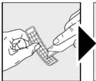
Reach setting / adjustment ⑫
The sensor has a maximum reach of 12 m. The detection zone can be optimised to suit individual needs. The shrouds provided are used for blanking out any number of lens segments or to shorten reach as required. This prevents the light from being activat-
ed unintentionally, e.g. by cars, passers-by etc. and allows to you to target danger spots. The shrouds can be divided or cut with a pair of scissors along the vertical and horizontal grooves. Turning the sensor unit permits final precision adjustment.
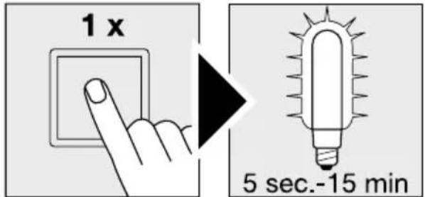
Manual override function ⑬
If a mains switch is installed in the mains supply lead, the light is capable of the following functions in addition to the simple ON/OFF function:
Sensor operation
1) Switch light ON (when light is OFF):
Switch OFF and ON once.
Light stays ON for the period selected.
2) Switch light OFF (when light is ON):
Switch OFF and ON once.
Light goes out or switches to sensor mode.
Manual override
1) Select manual override:
Switch OFF and ON twice. The light will stay ON for 4 hours (red LED lights up behind the lens). Then it returns automatically to sensor mode (red LED behind the lens is OFF).
2) Deactivate manual override:
Switch OFF and ON once. Light goes out or switches to sensor mode.
Important:
The switch should be actuated in rapid succession (in the 0.5- sec. range).
Soft light start
The sensor light features a soft light start function. This means that when turned ON, the light is not switched directly to maximum output but gradually
builds up brightness to 100% within the space of a second. Brightness is also gradually reduced when the light is switched OFF.
Troubleshooting
| Malfunction | Cause Remedy | |
| SensorLight without power | ■ Fuse faulty, not switched on, break in wiring■ Short circuit | ■ Fit new fuse, turn mains switch on; check wiring with voltage tester■ Check connections |
| SensorLight will not switch ON | ■ Twilight control set to night-time mode during daytime operation■ LED lamp faulty■ Mains switch OFF■ Fuse faulty■ Detection zone not properly targeted■ Internal electrical fuse has been activated (red LED behind the lens is lit/flashing constantly) | ■ Re-adjust (control 7)■ Change■ Switch on■ Fit new fuse, check connection if necessary■ Re-adjust■ Switch OFF SensorLight or check/change lamp and switch back ON again after 5 sec |
| SensorLight will not switch OFF | ■ Continuous movement in the detection zone■ Basic light level set to 50% | ■ Check detection zone and re-adjust if necessary■ Set basic light level to 0% (control 9) |
| SensorLight switches on when it should not | ■ Wind is moving trees and bushes in the detection zone■ Cars in the street are being detected■ Sudden temperature changes due to weather (wind, rain, snow) or air expelled from fans, open windows | ■ Change detection zone■ Change detection zone■ Change detection zone, change site of installation |
| SensorLight reach has changed | ■ Change in ambient temperatures | ■ Use shrouds to adjust detection zone accurately |
| Red LED behind the lens is lit/ flashing constantly although manual override is not selected | ■ Internal fuse activated | ■ Switch OFF SensorLight or check/change lamp and switch back ON again after 5 sec |
| LED lamp flickers | ■ For technical reasons, at various dimming levels | ■ Alter dimming level |
Operation / Maintenance
The SensorLight is suitable for switching light on automatically. Weather conditions may affect the way the SensorLight works. Strong gusts of wind, snow, rail or hail may cause the light to come on when it is not wanted because the sensor is unable to distinguish sudden changes of temperature from sources of heat. The detector lens may be cleaned with a damp cloth if it gets dirty (do not use cleaning agents).
text_image
Weather icon decomposition diagram showing sun and moon symbols with directional arrows and a checkmarkLight source can be changed by consumer.
Disposal
Electrical and electronic equipment, accessories and packaging must be recycled in an environmentally compatible manner.
Do not dispose of electrical and electronic equipment as domestic waste.
EU countries only:
Under the current European Directive on Waste Electrical and Electronic Equipment and its implementation in national law, electrical and electronic equipment no longer suitable for use must be collected separately and recycled in an environmentally compatible manner.
Manufacturer's warranty
This Steinel product has been manufactured with great care, tested for proper operation and safety in accordance with applicable regulations and then subjected to random sample inspection. Steinel guarantees that it is perfect condition and proper working order. The warranty period is 36 months, starting on the date of sale to the consumer. We will remedy defects caused by material flaws or manufacturing faults. The warranty will be met by repair or replacement at our own discretion. The warranty shall not cover damage to wear parts, damage or defects caused by improper treatment or maintenance. Further consequential damage to other objects shall be excluded.
The warranty will only be honoured if the product is sent to the appropriate Service Centre fully assembled and well packed with a brief description of the fault, receipt or invoice (date of purchase and dealer's stamp).
Repair service:
Please ask your nearest service centre how to proceed for repairing faults not covered by the warranty or occurring after the warranty expires.
3 YEAR MANUFACTURER'S WARRANTY
natural_image
Pure geometric diagram with concentric circles and radial lines, no text or symbols presenttext_image
Weather icon decomposition diagram showing sun and moon symbols with directional arrows and a checkmarknatural_image
Radar chart with concentric circles and radial lines, no text or symbols presenttext_image
Weather icon decomposition diagram showing sun and moon symbols with directional arrows and a checkmarktext_image
5 sec.-15 mintext_image
Weather icon decomposition diagram showing sun and moon symbols with directional arrows and a checkmarknatural_image
Polar coordinate system diagram with concentric circles and radial lines (no text or labels)text_image
Weather icon decomposition diagram showing sun and moon symbols with directional arrows and a checkmarknatural_image
Radar chart with concentric circles and radial lines, no text or labels visibletext_image
Weather icon decomposition diagram showing sun and moon symbols with directional arrows and a checkmarknatural_image
Polar coordinate system diagram with concentric circles and radial lines (no text or labels)text_image
Weather icon decomposition diagram showing sun and moon symbols with directional arrows and a checkmarktext_image
Weather icon decomposition diagram showing sun and moon symbols with directional arrows and a checkmarktext_image
Diagram showing a polar coordinate system with labeled axes and concentric circles, likely representing a physical or mathematical model.text_image
Weather icon decomposition diagram showing sun and moon symbols with directional arrows and a checkmarkRekkeviddeinnstilling/justering ⑫
text_image
Weather icon decomposition diagram showing sun and moon symbols with directional arrows and a checkmarknatural_image
Pure geometric diagram with concentric circles and radial lines, no text or symbols presenttext_image
Weather icon decomposition diagram showing sun and moon symbols with directional arrows and a checkmarktext_image
Weather icon decomposition diagram showing sun and moon symbols with directional arrows and a checkmarktext_image
Weather icon decomposition diagram showing sun and moon symbols with directional arrows and a checkmarktext_image
Weather icon decomposition diagram showing sun and moon symbols with directional arrows and a checkmarktext_image
Weather icon decomposition diagram showing sun and moon symbols with directional arrows and a checkmarknatural_image
Polar coordinate system diagram with concentric circles and radial lines (no text or labels)text_image
Weather icon decomposition diagram showing sun and moon symbols with directional arrows and a checkmarktext_image
Weather icon decomposition diagram showing sun and moon symbols with directional arrows and a checkmark3 ANI GARANTIA PRODUCATORULUI
text_image
Weather icon decomposition diagram showing sun and moon symbols with directional arrows and a checkmarktext_image
Weather icon decomposition diagram showing sun and moon symbols with directional arrows and a checkmarktext_image
Diagram showing a polar coordinate system with labeled axes and concentric circles, likely representing a physics or engineering concept.text_image
Weather icon decomposition diagram showing sun and moon symbols with directional arrows and a checkmarktext_image
Weather icon decomposition diagram showing sun and moon symbols with directional arrows and a checkmarknatural_image
Radar chart with concentric circles and radial lines, no text or labels visibletext_image
Weather icon decomposition diagram showing sun and moon symbols with directional arrows and a checkmarktext_image
Weather icon decomposition diagram showing sun and moon symbols with directional arrows and a checkmarktext_image
5 sec.-15 mintext_image
Weather icon decomposition diagram showing sun and moon symbols with directional arrows and a checkmarktext_image
Diagram showing a polar coordinate system with angular divisions and concentric circles, likely representing a physical or mathematical model.text_image
Weather icon decomposition diagram showing sun and moon symbols with directional arrows and a checkmark灯源可由终端客户更换。
废弃物处理
natural_image
World map silhouette in grayscale, showing continents and oceans without any text or labelsContact
www.steinel.de/contact