
MHSC2000E - Multitools EGO - Free user manual and instructions
Find the device manual for free MHSC2000E EGO in PDF.
| Product type | Cordless multi-tool |
| Brand | EGO |
| Model | MHSC2000E |
| Rated voltage | 56 V |
| Battery type | Lithium-ion (compatible BA1120E, BA2240E, BA2800, BA3360, BA4200) |
| Power head weight | 2.73 kg (without battery) |
| Pole hedge trimmer weight | 2.28 kg (without battery, without sheath) |
| Pole pruner extension weight | 1.89 kg (with guide protection) |
| Edger extension weight | 1.59 kg (without battery) |
| Blade length (hedge trimmer) | 51 cm |
| Max cutting capacity (hedge trimmer) | 26 mm |
| Guide bar length (pruner) | 250 mm |
| Chain pitch (pruner) | 9.5 mm |
| Cutting width (edger) | 38 cm |
| Cutting line diameter | 2.4 mm |
| Guaranteed sound power level (hedge trimmer) | 95 dB(A) |
| Guaranteed sound power level (pruner) | 104 dB(A) |
| Guaranteed sound power level (edger) | 96 dB(A) |
| Vibration (hedge trimmer, front handle) | 2.8 m/s² (K=1.5 m/s²) |
| Vibration (pruner, front handle) | 2.1 m/s² (K=1.5 m/s²) |
| Vibration (edger, front handle) | 1.1 m/s² (K=1.5 m/s²) |
| Lubrication type (pruner) | Chain and bar oil (20 ml reservoir) |
| Protection | Wear safety glasses, gloves, hearing protection and helmet recommended |
| Warranty | Check EGO policy at egopowerplus.com |
Frequently Asked Questions - MHSC2000E EGO
User questions about MHSC2000E EGO
0 question about this device. Answer the ones you know or ask your own.
Ask a new question about this device
Download the instructions for your Multitools in PDF format for free! Find your manual MHSC2000E - EGO and take your electronic device back in hand. On this page are published all the documents necessary for the use of your device. MHSC2000E by EGO.
USER MANUAL MHSC2000E EGO
EN Hedge trimmer attachment 5
Residual risk! People with electronic devices, such as pacemakers, should consult their physician(s) before using this product. Operation of electrical equipment in close proximity to a heart pacemaker could cause interference or failure of the pacemaker.
WARNING: To ensure safety and reliability, all repairs and replacements should be performed by a qualified service technician.
SAFETY SYMBOLS
The purpose of safety symbols is to attract your attention to possible dangers. The safety symbols and the explanations with them deserve your careful attention and understanding. The symbol warnings do not, by themselves, eliminate any danger. The instructions and warnings they give are no substitutes for proper accident prevention measures.
WARNING: Be sure to read and understand all safety instructions in this Operator's Manual, including all safety alert symbols such as "DANGER," "WARNING," and "CAUTION" before using this tool. Failure to follow all instructions listed below may result in electric shock, fire, and/or serious personal injury.
SYMBOL MEANING
SAFETY ALERT SYMBOL: Indicates DANGER,WARNING,OR CAUTION. May be used in conjunction with other symbols or pictographs.

WARNING: The operation of any power tools can result in foreign objects being thrown into your eyes, which can result in severe eye damage. Before beginning power tool operation, always wear safety goggles or safety glasses with side shields and a full face shield when needed. We recommend a Wide Vision Safety Mask for use over eyeglasses or standard safety glasses with side shields.
SAFETY INSTRUCTIONS
This page depicts and describes safety symbols that may appear on this product. Read, understand, and follow all instructions on the machine before attempting to assemble and operate it.
| Safety Alert | Indicates a potential person- al injury hazard. | |
| Read Operator's Manual | To reduce the risk of injury, user must read and under- stand the operator's manual before using this product. | |
| Wear Eye Protection | Always wear safety goggles or safety glasses with side shields and a full face shield when operating this product. | |
| Wear Ear Protection | Always wear ear protection when operating this product. | |
| 51cm | Blade Length | The length of the blade |
| ∅26mm | Cutting Capacity | Max. Cutting capacity of the blade |
| Keep hands and feet away from the cutting tool | Never attempt to operate your power tool with one hand. Loss of control of the power tool resulting in serious or fatal injury may result. To reduce the risk of cut injuries, keep hands and feet away from the cutting tool. Never attach a moving cutting tool with your hand or any other part of your body. | |
| 15m | Keep Bystanders Away | Ensure that other people and pets remain at least 15m away from the hedge trimmer when it is in use. |
| Do Not Expose To Rain | Do not use in the rain or leave outdoors while it is raining. | |
| CE | CE | This product is in accordance with applicable EC directives. |
EN
EN
| WEEE | Waste electrical products should not be disposed of with household waste. Take to an authorized recycler. | |
| XX | Noise | Guaranteed sound power level. Noise emission to the environment according to the European community's Directive. |
| mm Millimeter Length or size | ||
| V Volt Voltage | ||
| cm Centimeter Length or size | ||
| in. Inch | Length or size | |
| kg Kilogram Weight | ||
IMPORTANT SAFETY INSTRUCTIONS
WARNING! When using electric gardening appliances, basic safety precautions should always be followed to reduce the risk of fire, electric shock, and personal injury, including the following:
READ CAREFULLY BEFORE USE
KEEP FOR FUTURE REFERENCE
DANGER! Do not operate near electrical power lines.
The unit has not been designed to provide protection from electric shock in the event of contact with overhead electric lines, Consult local regulations for safe distances from overhead electric power lines and ensure that the operating position is safe and secure before operating the tool.
HEDGE TRIMMER SAFETY WARNING
DANGER! Keep hands away from blade. Contact
with blade will result in serious personal injury.
- Keep all parts of the body away from the cutter blade. Do not remove cut material or hold material to be cut when blades are moving. Make sure the switch is off when clearing jammed material. A moment of inattention while operating the hedge trimmer may result in serious personal injury.
-
On machines with a defined transport position (cutting blade folded flat against the hedge trimmer shaft): Never start the machine in the transport position, since the blades are not engaged in that position and you therefore cannot visually check to see that they will be stopped at idle when you start to adjust the cutting blade to the desired cutting position (where the blades are engaged).
-
Carry the hedge trimmer by the handle with the cutter blade stopped. When transporting or storing the hedge trimmer always fit the cutting device cover. Proper handling of the hedge trimmer will reduce possible personal injury from the cutter blades.
- Do not grasp the exposed cutting blades or cutting edges when picking up or holding the hedge trimmer.
-
Hold the power tool by insulated gripping surfaces only, because the cutter blade may contact hidden wiring. Cutter blades contacting a "live" wire may make exposed metal parts of the power tool "live" and could give the operator an electric shock.
-
Keep cable away from cutting area. During operation the cable may be hidden in shrubs and can be accidentally cut by the blade.
-
Check the hedge for foreign objects before operating, e.g. wire fences.
To reduce the risk of injury from loss of control, be absolutely sure that the cutting blade is clear of you and all other obstructions and objects, including the ground, because when the tool starts, the motor speed will be fast enough to engage and move the cutting blade on the tool. - Do not allow other persons in the general work area. Ensure that other people and pets remain at least 15m away from the hedge trimmer when it is in use.
- Never allow children to operate the hedge trimmer.
Use both hands when operating the hedge trimmer. Using one hand could cause loss of control and result in serious personal injury. - Do not overreach. Keep proper footing and balance at all times. Special care must be taken in slippery conditions (wet ground, snow) and in difficult, overgrown terrain. Watch for hidden obstacles such as tree stumps, roots and ditches to avoid fallen branches, scrub and cuttings. Be extremely cautious when working on slopes or uneven ground.
- Do not use on a ladder, rooftop, tree, or other unstable support. Stable footing on a solid surface enables better control of the hedge trimmer in unexpected situations.
-
Observe the cutting blades at all times - do not cut any area if the hedge that you cannot see. When cutting the top of a taller hedge, check the other side of the hedge frequently for bystanders, animals and obstructions.
-
Check damaged parts before further use of the hedge trimmer. Check for alignment of moving parts, binding of moving parts, breakage of parts, mounting, and any other condition that may affect its operation.
- Check the blade and motor mounting bolts at frequent intervals for proper tightness. Also, visually inspect blade for damage (e.g., bent, cracked, and worn). Replace the blade only with a blade from EGO™.
- Replace the blade if it is bent or cracked. An unbalanced blade causes vibration that could damage the motor drive unit or cause personal injury.
If the equipment should start to vibrate abnormally, stop the motor and check immediately for the cause. Vibration is generally a warning of trouble.
The trimmer shall be used to cut stems less than 26mm thick. - Trim only in daylight or in good artificial light.
- Do not use the battery-operated hedge trimmer in rain
ADDITIONAL WARNING
- Do not charge the battery pack in rain or in wet locations.
Use only with the battery packs and chargers listed SAVE THESE INSTRUCTIONS below:
| BATTERY PACK CHARGER | |
| BA1120E, BA2240E, BA2800, BA3360, BA4200 | CH2100E CH5500E |
The battery pack must be removed from the appliance before it is scrapped.
The battery shall be disposed of safely.
- Do not dispose of the battery in a fire. The cells may explode. Check with local codes for possible special disposal instructions.
- Do not open or mutilate the battery. Released electrolyte is corrosive and may cause damage to the eyes or skin. It may be toxic if swallowed.
CAUTION! The electrolyte is a dilute sulfuric acid that is harmful to the skin and eyes. It is electrically conductive and corrosive.
Exercise care in handling batteries in order not to short the battery with conducting materials such as rings, brackets, and keys. The battery or conductor may overheat and cause burns.
- Battery tools do not have to be plugged into an electrical outlet; therefore, they are always in operating condition. Be aware of possible hazards even when the tool is not operating. Take care when performing maintenance or service.
- Remove the battery pack before servicing, clean or removing material from the tool.
EN
- Replacement Parts - When servicing, use only identical EGO replacement parts. Use of any other accessory or attachment may increase the risk of injury.
Have your power tool serviced by a qualified repair person using only identical replacement parts. This will ensure that the safety of the power tool is maintained.
- Do not wash with a hose; avoid getting water in motor and electrical connections.
- Store the tool in a dry and high or locked location out of reach of children.
If situations occur that are not covered in this manual, use care and good judgment. Contact the EGO Service Center for assistance.
Save these instructions. Refer to them frequently and use them to instruct others who may use this tool. If you lend this tool to someone else, also lend these instructions to them to prevent misuse of the product and possible injury.
SAVE THESE INSTRUCTIONS
NOTE: SEE YOUR POWER HEAD OPERATOR'S MANUAL FOR ADDITIONAL SPECIFIC SAFETY RULES.
SPECIFICATIONS
| Blade Length 51 cm | ||
| Cutting Capacity 26 mm | ||
| Weight (Without battery pack) 2.28 kg | ||
| Measured sound power level \( L_{WA} \) | 92.3 dB(A)K=2.72 dB(A) | |
| Sound pressure level at operator's ear \( L_{PA} \) | 80.4 dB(A)K=3 dB(A) | |
| Guaranteed sound power level \( L_{WA} \)(measured according to 2000/14/EC) | 95 dB(A) | |
| Valuation of vibration \( a_h \) | Front-assist handle | \( 2.8\mathrm{\;m}/{\mathrm{s}}^{2} \)\( K = {1.5}\mathrm{\;m}/{\mathrm{s}}^{2} \) |
| Rear handle | \( 3.0\mathrm{\;m}/{\mathrm{s}}^{2} \)\( K = {1.5}\mathrm{\;m}/{\mathrm{s}}^{2} \) | |
The above parameters are tested and measured equipped with power head PH1400E;
The declared vibration total value has been measured in accordance with a standard test method and may be used for comparing one tool with another;
EN
The declared vibration total value may also be used in ADJUSTING THE CUTTING BLADE a preliminary assessment of exposure. When the hedge trimmer is removed
NOTICE: The vibration emission during actual use of the power tool can differ from the declared value in which the tool is used; In order to protect the operator, user should wear gloves and ear protectors in the actual conditions of use.
PACKING LIST
| PART NAME QUANTITY | |
| Hedge Trimmer Attachment 1 | |
| Wrench 1 | |
| Blade Scabbard 1 | |
| Operator's Manual 1 |
DESCRIPTION
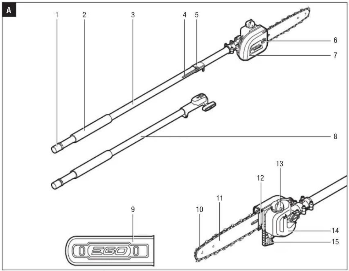
KNOW YOUR HEDGE TRIMMER ATTACHMENT (Fig. A)
- Cutting Blade
- Quadrant
- Trigger
- Hedge Trimmer Shaft
- Soft Sleeve
- End Cap
- Adjusting Lever
- Gear Case
- Wrench
- Blade Scabbard
- Tip Protector (Optional, SOLD SEPARATELY)
ASSEMBLY
WARNING: If any parts are damaged or missing, do not operate this product until the parts are replaced. Use of this product with damaged or missing parts could result in serious personal injury.
WARNING: Do not attempt to modify this product or create accessories not recommended for use with this hedge trimmer. Any such alteration or modification is misuse and could result in a hazardous condition leading to possibly serious personal injury.
WARNING: Never attach or adjust any attachment while the power head is running or with the battery installed. Failure to stop the motor and remove the battery may cause serious personal injury.
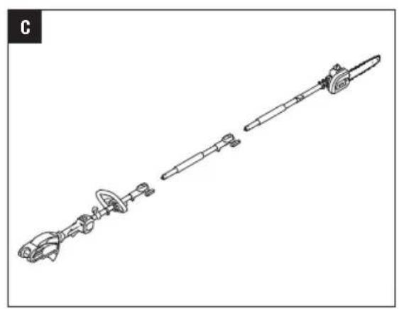
When the hedge trimmer is removed from the package, it is folded in its storage position where the cutting blade is against the shaft (Fig. B). It is recommended to adjust the cutting blade to a suitable working position before attaching it to the power head.
There are 12 possible working positions. The angle of the cutting blade can be adjusted upwards in 4 stages from 0^ (straight) to 45^ , and downwards in 7 stages from 0^ to 90^ (right angle facing down) (Fig. C).
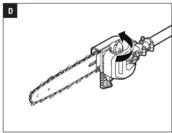
- Press the trigger on the adjusting lever and meanwhile rotate the adjusting lever to adjust the cutting blade to the desired cutting position (Fig. D).
- Once the desired position has been reached, release the trigger. An audible click indicates that the locking pin is engaged in the quadrant, right located into place (Fig. D).
Fig. D parts description see below:
| D-1 Quadrant |
| D-2 Locking Pin |
WARNING: To reduce the risk of injury, carry out the adjustment only when the cutting blades are at a standstill. Never touch the blades while making adjustments.
WARNING: To reduce the risk of injury, always stop the tool and fit the blade scabbard before moving the cutting blade to the storage position or from the storage position to the normal working position.
CONNECTING/REMOVING THE HEDGE TRIMMER ATTACHMENT TO THE POWER HEAD
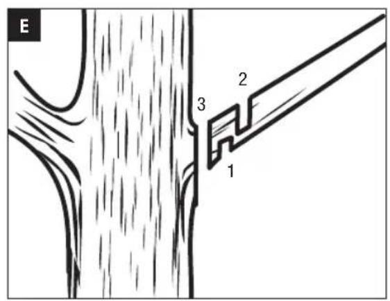
This hedge trimmer attachment is designed for use with EGO 56V LITHIUM-ION Power Head PH1400E. Besides top cutting, there is a side-cutting position in the hedge trimmer shaft for connecting with the power head (Fig. E). Detail working techniques please see "WORKING TECHNIQUES" section in this manual.
Fig. E parts description see below:
| E-1 | Top Cut Position |
| E-2 | Side Cut Position |
See "INSTALLING AN ATTACHMENT TO THE POWER HEAD" section in the power head PH1400E operator's manual for connecting the hedge trimmer to the power head.
See "REMOVING THE ATTACHMENT FROM THE POWER HEAD" section in the power head PH1400E operator's manual to remove the hedge trimmer from the power head.
MOUNTING THE TIP PROTECTOR (Optional)
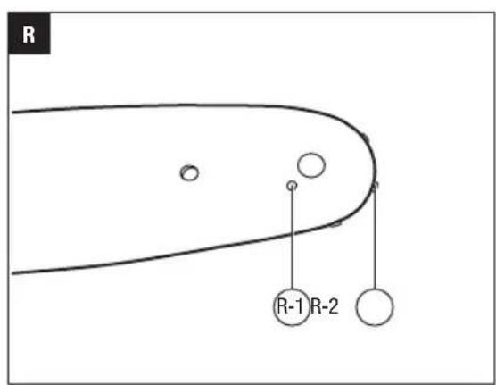
- Use a 3mm hex wrench to remove the short bolt, plain washer, bush and nut at the end of the cutting blade (Fig. F). Save the plain washer, bush and nut for reassembly.
Fig. F parts description see below:
| F-1 Nut F-3 Plain Washer | ||
| F-2 Bush F-4 Short Bolt |
- Align the tip protector with the bulge on the cutting blade and mount it into place. Secure it with the new long bolt and nut as well as the saved washer, bush and nut (Fig. G).
Fig. G parts description see below:
| G-1 Nut G-4 Bush | ||
| G-2 Tip Protector G-5 Plain Washer | ||
| G-3 Nut G-6 Long Bolt |
OPERATION
DANGER: Never cut near power lines, electric cords, or other electric sources. If the cutting blades jam on any electrical cord or line, DO NOT TOUCH THE CUTTING BLADE OR THE ALUMINUM POLE! THEY CAN BECOME ELECTRICALLY LIVE AND MAY BE VERY DANGEROUS.
Continue to hold the hedge trimmer by the insulated rear handle or lay it down and away from you in a safe manner. Disconnect the electrical service to the damaged line or cord before attempting to free the cutting blade from the line or cord. Contact with the cutting blade, other conductive parts of the hedge trimmer or live electric cords or lines will result in death by electrocution or seriousinjury.
WARNING: Do not allow familiarity with this product to make you careless. Remember that a careless fraction of a second is sufficient to inflict serious injury.
WARNING: Always wear eye protection, along with hearing protection. Failure to do so could result in objects being thrown into your eyes and other possible serious injuries.
Before each use, inspect the entire product for damaged, missing, or loose parts such as screws, nuts, bolts, caps, etc. Tighten securely all fasteners and caps and do not operate this product until all missing or damaged parts are replaced.
WARNING: To prevent serious personal injury, remove the battery pack from the tool before servicing, cleaning, changing attachments or removing material from the unit.
After each use, clean the tool.
See the Maintenance section for cleaning instructions.
APPLICATIONS
You may use this product for trimming the hedges, shrubs, scrub, bushes and similar material with a branch diameter of less than 026mm
NOTICE: The tool is to be used only for its prescribed purpose. Any other use is deemed to be a case of misuse.
USING THE HEDGE TRIMMER WITH POWER HEAD
WARNING: Dress properly to reduce the risk of
injury when operating this tool. Do not wear loose clothing or jewelry. Wear eye and ear/hearing protection. Wear heavy, long pants, boots and gloves. Do not wear short pants or sandals or go barefoot.
PREPARATION FOR CUTTING:
- Adjusting the cutting blade to the desired working position.
- Remove the blade scabbard from the cutting blade.
- For safe and better operation, put on the shoulder strap across the shoulder. Adjust the shoulder strap into a comfortable operating position. Following the instructions in the section "MOUNTING THE SHOULDER STRAP" in PH1400E operator's manual to attach the shoulder strap onto the power head.
WARNING: The shoulder strap is also a quick
release mechanism in hazardous situation. When an emergency occurs, take it off your shoulder immediately, no matter what way the strap is in.
WORKING TECHNIQUES
Horizontal Cutting (with cutting blade at an angle): Cut close to the ground from a standing position, e.g. low shrubs.
Swing the cutting blade up and down as you move along the hedge - use both sides of the cutting blades, do not rest the cutter blade on the ground (Fig. H).
EN
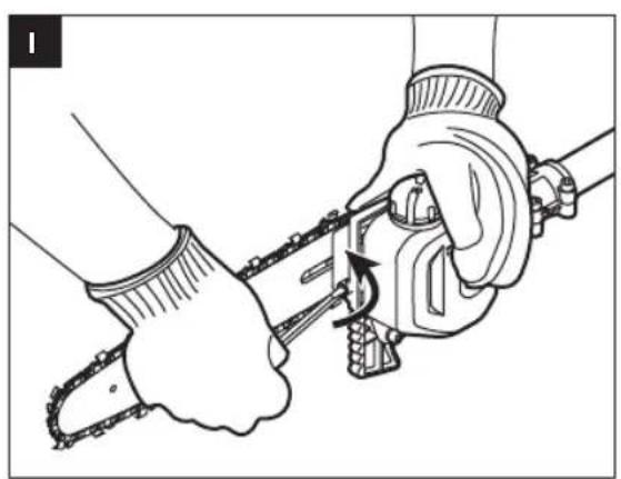
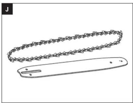
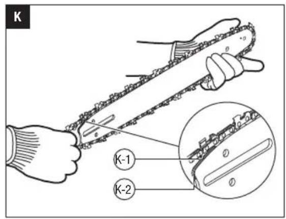
Horizontal Cutting (with straight cutting blade)
Hold the cutting blade at an angle of 0^ to 10^ as you swing the hedge trimmer horizontally. Swing the cutting blade in an arc towards the outside of the hedge so that the cuttings are swept to the ground (Fig. I, J & K).
Recommendation: Only cut hedges that are no more than chest height in this working position.
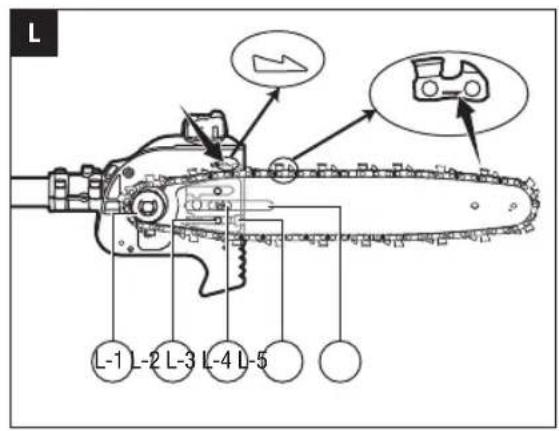
Vertical Cutting (with cutting blade at an angle):
Cutting without standing directly next to the hedge, e.g. flowerbed between operator and hedge.
In this cutting position, for your better control of the hedge trimmer, it is recommended that connect the hedge trimmer with the power head at the side-cutting position (see Fig. E).
Swing the cutting blade up and down in an arc as you move along the hedge - use both sides of the cutting blade (Fig. L).
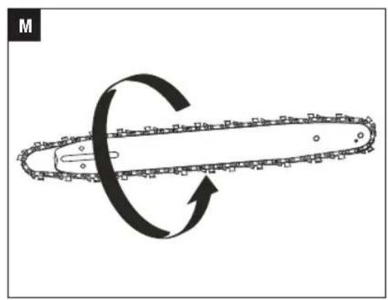
Vertical Cutting (with straight cutting blade):
Extra long reach without the need for other aids.
Swing the cutting blade up and down in an arc as you move along the hedge - use both sides of the cutting blade (Fig. M).
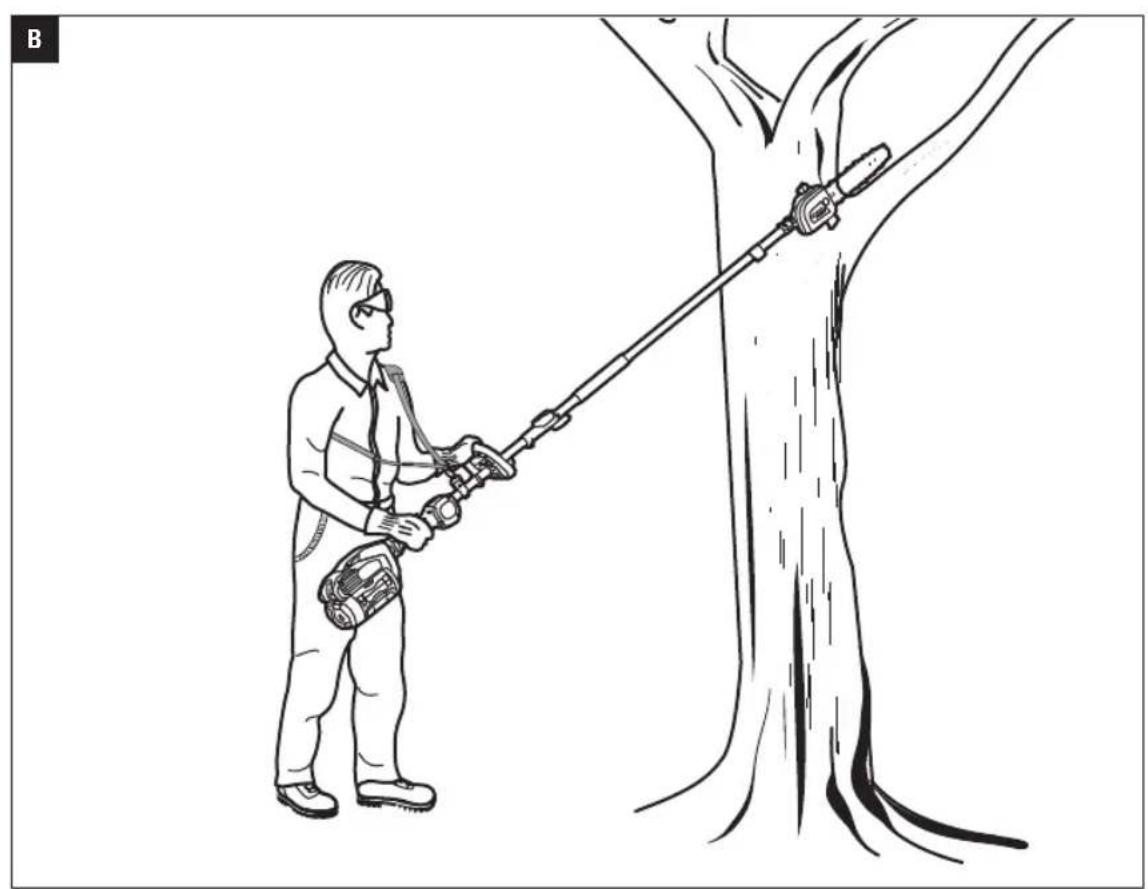
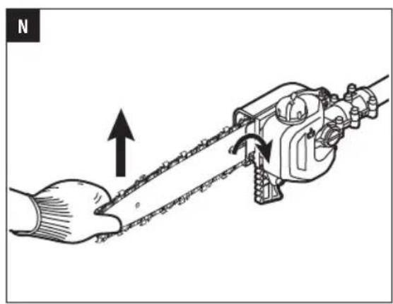
Overhead Cutting (with cutting blade at an angle)
Hold the hedge trimmer vertically and swing it in an arc to make maximum use of its reach (Fig. N). For extreme high hedge, the extension pole is suitable for aids in trimming.
WARNING: Any working position above head height is tiring. To minimize the risk of accidents, work in such positions for short periods only. Set angle of adjustable cutting blade to maximum so that the tool can be held in a lower, less tiring position (with shoulder strap) while still providing adequate reach.
TO START/STOP THE TOOL
See "STARTING/STOPPING THE POWER HEAD" section in the power head PH1400E operator's manual.
MAINTENANCE
WARNING: Before inspecting, cleaning or servicing the unit, stop the motor, wait for all moving parts to stop, and remove the battery pack. Failure to follow these instructions can result in serious personal injury or property damage.
WARNING: When servicing, use only identical replacement parts. Use of any other parts can create a hazard or cause product damage. To ensure safety and reliability, all repairs should be performed by a qualified service technician.
GENERAL MAINTENANCE
Avoid using solvents when cleaning plastic parts. Most plastics are susceptible to damage from various types of commercial solvents and may be damaged by their use. Use clean cloths to remove dirt, dust, oil, grease, etc.
CLEAN THE UNIT
Use a soft brush to remove debris from all air intakes and cutting blade.
To remove pitch and other sticky residue, spray the blades with resin solvent. Run the motor briefly so that the solvent is evenly distributed.
- Do not use any strong detergents on the plastic housing or the handle. They can be damaged by certain aromatic oils, such as pine and lemon, and by solvents such as kerosene. Moisture can also cause a shock hazard. Wipe off any moisture with a soft dry cloth. Never use water for cleaning the tool.
SHARPENING THE CUTTING BLADE
When cutting performance and behavior begin to deteriorate, i.e. blades frequently snag on branches: Resharpen the cutting blades.
It is recommended to have the cutting blades resharpened by a qualified service technician.
NOTICE: Do not operate your hedge trimmer with dull or damaged cutting blades. This may cause overload and will give unsatisfactory cutting results.
LUBRICATING THE BLADE
To prevent rust, it is recommended to lubricate the blades with anti-rusting oil when it is stored for long time.
WARNING: Blades are sharp. When handling the blade assembly, wear non-slip, heavy-duty protective gloves. Do not place your hand or fingers between blades or in any position where they could get pinched or cut. NEVER touch blades or service the unit with battery pack installed.
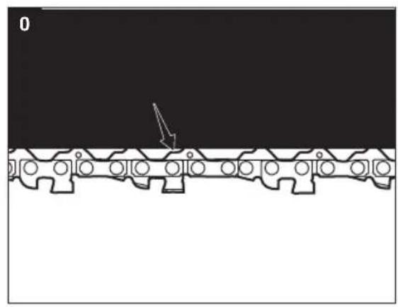
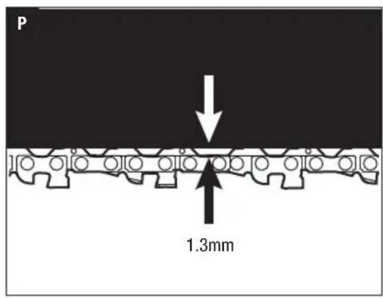
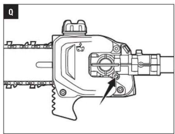
The transmission gears in the gear case need to be lubricated periodically with gear grease. Check the gear case grease level about every 50 hours of operation by removing the sealing screw on the gear case. There are three sealing screws with one on the side and two on the top.
If no grease can be seen on the flanks of the gear, follow the steps below to fill with gear grease up to 3/4 capacity.
Do not completely fill the transmission gears.
- Depending on which screw you are removing, hold the hedge trimmer on its side or lay it on its back so that the sealing screw to be removed is facing upwards (Fig. 0 & P).
- Use the wrench provided to loosen and remove the sealing screw.
- Use a grease syringe (not included) to inject some grease into the screw hole; do not exceed 3/4 capacity.
- Tighten the sealing screw after injection.
STORING THE UNIT
Remove the battery pack from the tool.
Clean the tool thoroughly before storing it.
Put on the blade scabbard onto the cutting blade before storing or transporting. Use caution to avoid the sharp teeth of the blades. For saving space, it is recommended to fold the hedge trimmer to its storage position (see Fig. B).
If the hedge trimmer is removed from the power head and stored separately, fit the end cap on the attachment shaft to avoid dirt getting into the coupler.
- Store the unit in a dry, well-ventilated area, locked-up or up high, out of the reach of children. Do not store the unit on or adjacent to fertilizers, gasoline, or other chemicals.
Protecting the environment

Do not dispose of electrical equipment, battery charger and batteries/ rechargeable batteries into household waste!
According to the European law 2012/19/EU, electrical and electronic equipment that is no longer usable, and according to the European law 2006/66/EC, defective or used battery packs/batteries, must be collected separately.
If electrical appliances are disposed of in landfills or dumps, hazardous substances can leak into the groundwater and get into the food chain, damaging your health and well-being
EC DECLARATION OF CONFORMITY

EN
We, EGO EUROPE GMBH.
Declare that the product 56V lithium-ion cordless hedge trimmer attachment HTA2000, equipped with power head PH1400E
Complies with the essential health and safety requirements of the following Directives:
2006/42/EC, 2014/30/EU, 2011/65/EU, 2000/14/EC
Standards and technical specifications referred to: EN 60745-1, EN ISO 10517, EN 55014-1, EN 55014-2
Measured Sound Power Level: 92.3 dB(A)
Guaranteed Sound Power Level: 95 dB(A)
* (The above parameters are tested and measured equipped with the power head)

Peter Melrose Dong Jianxun Managing Director of EGO Europe GmbH Chervon
Quality Manager of
* (Authorized representative for CHERVON and responsible for technical documentation)
01/12/2016
EN TROUBLESHOOTING
| PROBLEM | CAUSE SOLUTION | |
| Hedge Trimmer does not work. | The battery pack is not attached to the hedge trimmer. No electrical contact between the hedge trimmer and battery. The battery pack is depleted. The lock-off button is not depressed before pressing the trigger. The battery pack or power head is too hot. The blade is jammed. The hedge trimmer is not well connected with the power head. | Attach the battery pack to the hedge trimmer. Remove battery, check contacts and reinstall the battery pack. Charge the battery pack. Press down the lock-off lever and hold it, then depress the trigger to turn on the tool. Allow the battery pack or power head to cool until the temperature drops below 152°F (67°C). Remove the battery pack from the tool. Remove the obstruction carefully and then reinsert the battery and restart the tool. Disconnect the hedge trimmer from the power head. Reconnect them following the section "INSTALLING AN ATTACHMENT TO THE POWER HEAD" in PH1400E operator's manual. |
| Excessive vibration or noise. | Dry or corroded blades. Blades or blade support is bent. Bent or damaged teeth. Loose blade bolts. | Lubricate the blades. Replace with a new blade or support. Contact EGO service center for blade or support replacement. Replace with a new blade or support. Contact EGO service center for blade or support replacement. Tighten the blade bolts. Using a 3mm wrench, (not included), turn the bolt clockwise to tighten. |
WARRANTY
EGO WARRANTY POLICY
Please visit the website_egopowerplus.com for full terms and conditions of the EGO Warranty policy.
2006/42/CE, 2014/30/UE, 2011/65/UE, 2000/14/CE
2006/42/CE, 2014/30/UE, 2011/65/UE, 2000/14/CE
2006/42/CE, 2014/30/UE, 2011/65/UE, 2000/14/CE
Normas e caracteristicas sociales relatives a:
EN 60745-1, EN ISO 10517, EN 55014-1, EN 55014-2
Nivel de potencia do som medico: 92,3 dB(A)
VEILIGHEIDSWAARSCHUWINGEN VOOR HEGGENSCHAREN
HET APPARAAT SCHOONMAKEN
HET APPARAAT OPBERGEN
E-1 $tilling for klipning at top
E-2 $illing for klipning at sider
RENGORING AF APPARATET
OPBEVARING AF APPARATET
| D-1 | Kvadrant |
| D-2 | Laseplugg |
ADVARSEL: For a redusere risikoen for skade skal reguleringen bare gjores nár skjarebladet star stille. Unnga a ta pa bladene under justeringen.
ADVARSEL: For a redusere risikoen for skade skal du alltid stoppe verktoyet og sette pa sliren for du setter skjarebladet i transportstilling ellr ransportstilling til normal arbeidsstilling.
KOBLE HEKKTRIMMEREN PÄ/AV MOTORENHETEN
Fig. G parts description see below:
| G-1 | Mutter G-4 Hylse | ||
| G-2 | Tuppbeskytter G-5 Underlagsskive | ||
| G-3 | Mutter G-6 Lang sknue | ||
DRIFT
A FARE: Unngå Å klippeær kraftlinjer, elektriske ledninger erler andre el-kilder. Hvis skjarebladene setter seg fast i en elektrisk ledning, MÅ DU IKKE TA PÁ SKJÆREBLADENE ELLER ALUMINIUMSSTANGEN! DE KAN BLI “LEVENDE” OG DERMED SVERT FARLIGE.
GENERELT VEDLIKEHOLD
NCOJb30BaTbCBAmte C DpyMm CNMBONAMN NNI KNTORpAMMAMN.

HIMAHHE! NcnoJIb3OBAHne IIObIX MEXAHUeCKNX INCTpymeHTOB MOKET npBecTN K NOIaHaHHIO NOCTOPOHHX npEmTOB B rna3a, YTO MOKET CTaTB npHInHO cepBe3HBx TpaBM. Pn pa6oTe c TAKIM IHCTpymeHTOM BCERda HadeBaIte 3aunTHbIE OUYK, OUYC C 6OKOBbIMN UNTkAMn IINI NueBle UNTKN. IOBepx 3aunTHbIX OOKOB peKOMeHNyETCR HaeBaTb 3aunTHyIO Macky Wide Vision nIN NCNoJIb3OBaTb CTaNaprTHbIE 3aunTHbIE OUYC C 6OKOBbIMN UNTkAMn
MEPbI INPEIOCTOPOXHOCTN
Ha daHHoI cTpaHnue OINcAHI npEynpexKaIOUe CMBOJI, KOToPbIE MOrT pNcYrCTBOBaTb Ha N3JeIMI. IpoHTaTe n pa36epntecb co BCEMN INHCTpyKJMAH HA INHCTpyMeHTe n CO6KnOJaTe INx npn C6OpKe n 3KcIIyatauM INHCTpyMeHTa.
IPEIOCTEPEXEHN O5 ONACHOCTNIPINcNoJIb3OBAHM KYCTOPE3A
ONACHO!PykndoJnxhblHaxoOntbcHa Ha6e3onachompacctoHHnOTpexyuero3neMeHTa. PpIKoCHOBHeNkpekyuemy3neMeHTy moKET npNBecTKN cepbe3HbIM TpaBMam.
CneHTE 3a TEM, YTO6bI cactn Tena HaxoDnncb Ha
pacctoHHN OT pexyUero 3nemeHTa. He y6npaTe
cpe3AHbIe qactn n He depKNTe o6pe3aEMbIE
qactn BO BpemraBpaueHnpeKyuero 3nemeHTa.
PepeO uOncTKoN OT 3acptpBux MATEpnaIOB
y6eHNTecb, YTO yCTPOINCTBO BIKNUOHeO.
JaKe KpaTkoBpeMeHHa HEBHMAteJIbHOCTb PnI
HCNoJIb3OBaHHu yCTPOINCTBa MOKeT PnIBecTN K
cepbe3HbIM TpaBMAM.
PnmeHneIyctpoCTBcONpeDeneHHbIM TpaHCnOpTnpoBOuHbIMNIOXKeHNEM (pexynn 3JemeHT CNOxEN BnIoTHyIO K Bany Kyctope3a). HkOrda He 3anyckaTe yCTpOCTBO B TpaHCnOpTnpoBOUHOM NIOXKeHN, TAKKIN 3TOM pexyuNE 3JemeHTbHe HaxoJrTCB 3aueJIeHNu NEBO3MOXHO Bu3yAalHo y6eITbC8 TOM, YTO OHN OCTaHOBTcRA HxOIOCTOM XOdy Nepei HaaylOM perYInPOBKn IX NIOXKeHN.
Bo BpemnpeHocn KcTope3 Heo6xOIMO depKaTa 3a pyKoTky. Pekyun 3IeMeHT He doJKeH Bpaatbcr. Bo Bpemr TpaHcnpotnpOBKn Hxpanenny pekuynn 3IeMeHT DOJIKeH 6bIt 3akpyxnom.HaJnxJaee IcNoB3OBAHne KcTope3a CHNkaet pncnnoyehn TpaBM Bpe3ynbTaTe KOHTAKTa CpeKyuIM 3IeMeHTOM.
PnO6paueHHcHCTpyMeHTOM He 6epntecb3a OTKpbTbIe pexyuune 3neMeHTbI Hnpexyuine Kpa.
-ДерхиTe 3ЛeКТПОНСТРМЕNT TOЛБКо 3a NOBepxHOCTH C 3aUHTbIM NOKpbITINEM, TAK KAK HOK MOXET KacaTbCkPbIToN 3ЛeKTPONPOBODNK. KacaHne peKyuIM 3IeMENTOM PNOBODKN IOI HAnpRKeHEM MOKET NepeDaTb HAnpRKeHMe HA MetaJIUNHeCKNe YactN 3ЛeKTPOMHCTPМЕNTa I PrnBeCTN K NopaxKeHIO ONEATOPA 3ЛeKTPNECKIM TOKOM.
- DApKInTe Ka6eBnNoaBHe OT pexyux 3IeMeHToB. Bo BpemNcOnb3oBaHnna Ka6eB MoKeT 3aTePraTcB KcyTx N cyuHNO nOaTb NoD pexyui 3IeMeHt.
Ipepa60To npoBpTe KnByIO n3ropoDb Ha Hauuue noctopoHnx o6bekTOB (HaNPmep, npoBOJouhIx orpaKaDeHH).
YTO6bI CHN3NTb pNCK NONYeHn TpaBM npn notepe KOHTpOJIa, Heo6xOdIma a6cONHOthra yBepeHHocTb B TOM, YTO peKyuJni 3JeMeHT He KacaetcOnepaTopa INpynx npenrTCTBn I O6bEkTOB, B TOM qNCNE 3emn, NockoJIbky npn 3anycke IHCTpyMeHTa CKOpOCTb BpaueHn DBnraTeJRAJBIAETC DOCTaTOUHO BlicOKoI dJa 3axBaTa INpeMeueHn peKyuJero 3JeMeHTa.
He donyckaTe noctopOHnHex B pa6oyu 30hy. Y6eNTecb, yTO dpyTne IIOU IN KINBOTHIbe HAXOJATcH paacctoAHn He Mehee 15 M ot pa6otaUeTo yCTpOCTBa.
He no3BONJte DeTAM mCnonb3OBaB kyctope3.
Pn pa6ote cyptpoiCTBOM ydepKBAHTe erO DByMa pykam. Pn ydepKBAHm OHOy pyko BO3MOxHa Nopep KOnTpOJa, YTO MOXET npNBecTN K cepbe3hblm TpaBMAM.
He nepehanpraaTecb. Bcerda coxpaHnTe yctoynBOe noLoXeHne n paBHOBecne. Heo6xoIMo Co6IIOaTB oO6yIO octopoxHOCTb Ha cKoJIb3kOM NOKpBTIN (MOKpar 3emJI, CHER), a TAKKE B CNOXHOJ 3apocwe MeCTHOCTN.CneDHTe 3a CkPbITbIMn IpenTCTBnMM, TAKIM KAK NH, KOPHN KAHABbl. M36eaiTe ynaBux BeTOK, KYCTAPHKOB IV OBe3KOB. BydtE Oco6EH0 BHmATEJIbHbI npn pa6ote Ha CKNoHax HnepOBHOI NOBepxHOCTN.
He nCnoB3yIte yCTpoIcTBO Ha IeCTHnIax, KpbIax, DepeBbIx INpyrIX HeYCTOuINbIX onopax. YCToIuINBOE NOIOJKeHne HA TBepDOn NOBEPXHOCTN N03BOJnET JLyIe KOHTPOJIuPObaTB yCTPOIcTBO B HEnpeBnIDEHbIX CNTyaIcx.
IocTOrHNO DePKeHTe peKyUne 3JeMeHTbI B noIe 3peHn. He cpeaTe paCTnteBHOCTb, ecn ee He BuNDHO. Pnp Cpe3AHn BEPxHe YacTn BbICOKo N3rOPOu nepNoOnueckn npOBepaIte, yTO C dpyroT CTOPOHbI N3rOPOu Het NoCTOPOHnx IuC, XIBOTbIX n IpenraTcBn.
IpeKkDbIMnCNoB3OBaHMe yctpoiCTBa npOBepIe erHa HAnHne NOBpeKDeHHbIX qacte. IpOBePbTe DBNxyuieCe qactn Ha npAanBbHOCTb BbipAanBbAHn n CcHnEHN, a TAKKe BCE OCTaBbHe qactn yCTPOiCTBa HA HANHne NOBpeXdHn, HAdexHoCTb KpeHnHn n DpyrNe ycNoBn, KOtOpbl E MOrTy NOBnTb Ha paBoTy yCTpoiCTBa.
-периончеси npовергnte Наджсьфкcaиpekyшeroлемента и кpenжнбхбогтOB.TakkeBn3yaJIbHo npовергnte pekyшилем entHaHannue nobpeckdenn (HanpIMep, n3r6OB, tpeuHn npn3hakOB n3Hoca).ДдЯ 3amehblncnoIb3ynte TOnbkopekyшилем ent EGO™.
3aementhepexyuun 3nemHT,ecn OH coHynncn Tpchyn. Hec6banaHcnpoBaHbI pexyuun 3nemENT Bb3bBAeT Bn6paunO, KOtopa MoKET npBecTN K NOBpeXdEHIO DnIRatela YCTPOINCTBA INN TPaBMam.
EcnnyyctpoiCtBOye3MepHO Bn6puyET,BykHIOHTe DBnraTeN HEmeIeHNO BbIaCHNTpePmHy.ObbHOBB6paun yka3bBaet HA Bo3NHKOHeHne npo6nembl.
YcTPOIcTBMOKETNCHOB3OBaTbCRAJINpe3KNCTe6JIeTOnUHHOHe6Oone 26 MM.
Pa6oTaTe ToIbKO pN DHeBHom CBeTe IIN XopoUeM NCKyCCTBeHHOM OCBeueHm.
He nCnoIb3yIte aKkymyIaTOpHoe yCTpoIcTBO noDdoKdEm.
DONOHINHTIbHbIE INPEyUNPEXJENHIA
He 3apjkaite aKkyMnyTop noDdoxJemnn BO BnaXbIy yCNOBnX.
IcnoNb3yUte TOnbKO aKkMyJrTopbI N 3apAaHbIe yctpoCTBa EGO.
| AKKUMЛЯTOPHА BATAPЕ | ЗAPДНOE УстюйСТВО |
| BA1120E, BA2240E, BA2800, BA3360, BA4200 | CH2100E CH5500E |
PpeJeemBb6paCbIBaTb yCTpoINCTBO,Heo6xOIMOn 13BneYb aKKyMnTOp.
AkkymyIantop Heo6xOIMO yTNIN3npoBaTb 6e30nacHbIM cnoc6om.
He 6pocaiTe akkmyIaTOpbI B orOHB. AkkmyIaTOpbIMORYB3OpBaTbC.O3HakOMbTEcB C MeCTbIMN HOPMaMn IN paBnAmn, KOTOpbIE MOrY T coepKaTbCneuaJIbHbe INCHpyKUIN NO yTuIN3aUIN.
He BckpbibaTe Hn DeOpMpye AkkmyIaTOp BbTEKm 3JIeKTPoINr MOKe TcTaB nPunHoi Kopp03m n PnBeCTN K NOBpeJdeHIO rna Nnn KOxN. OH TokChyeh npn pOrNaTbHaBHn.
BHUMAHNE! 3neKtpoNT npedctabnreT co60 pa36abHHeHHyO cepHy KcNToY, KOtopa OnaCha dno Koxn rna. OHa 3neKtpnpoBOnHa n arpeccNBHa.
Будte octopokhbl npn obpaueHn c
akymyIaTOpamn, YTo6bl He 3aMKHyTb KOHTaTbI
npdMeTAMN N3 pNoBDAuX MATEpHaJIOB, TAKMn
kak konba, 6pacnetbl KlnOu. AkmyIaTOp nnn
KOHTaKT MOrY TpepeTbCn Bbl3BaTb OKOrn.
Pa60aHue OAKyMyIaTOPOB HnCTpyMeHTbI He Tpe6yeTcnoKIOUoATb Kpo3eTe 3JeKtpocetn, NO3tOMY OHN BcERda IOTOBbl KNCNOB3OBAHIO. POMHNTe OBO3MOXHOCTN BO3HNKHOBEHn ONaChbIX CNYaui DaXe KOra yCTpOCTBO He NCNoJIb3yETcR. Co6nOJaTe OTOPOXHOCTb PnB BYINONHeHH TeXHueCKOrO 6CnykBaHn INI pEMoHTa.
N3BLeKeHTe aKKyMnyTOp nepei BblonHeHnem 06cnyxmbAHn, OCHCTKN Hn ydaJIeHN MaTePnana n3 BBICOTope3a.
3anachbteyactn.PnppeMOHTeNCNOB3yNTeTOnbko NDENTHcHBe 3anachbte yactn EGO.NcNoB30BaHne Dpynx npHaJNeXHOcte Hnn pncno6HeH MoKet PnIBecTN K NOyHuHIO TpaMbbl.
Pemont3neKtpOnHCTpyMeHTa donxhen npOn3BOoNTbC KBAHnHnIpOBaHHbIM CneuaHcTOM C HcNoJIb3OBAHHem TOnbKO IeHTuHBix 3anaChbIX Yactei.3To o6ecneHT 6e3onachyio pa60Ty 3neKtpOnHCTpyMeHTa.
He MoTe yCToPcTBo n3 uHaHra. M36eaiTe nonaHaHn BObblB DBrAteIb n 3JeKtpueckne coeDHHHeHn.
XpaHHTe yCTPOIcTBO B CYXOM, BBICOKOM NIN 3aKpbITOM MecTe, HEOCTyHOM DnI DETeN.
Pn BO3HKnHOBEN H CNTyaun, He ONncAHbIX B DaHHOM pyKOBOcTBe, CO6HOnaTe OCTopoxHOCTb I pyKOBOCTByTECb 3dpaBBIM CMBICNOM. O6paTInTeCB B cepBnchBn ceHTp EGO 3a NOMOsbIO.
CoxpaHnTe DaHHbIe HNCTpyKun. Perynpho npocMaTPBaIte Ix N ppeOCTaBnIte IIN O3HakOMJIeHNr Dpym NOnb3ObaTeIeM. OdaKNBaK KOMy-IM6 yCTpoIcTBo, nepeaIte TaKke daHHbIe INCHCTpyKun IINppeOTBpaUeHHeHnpaBInbHorO INCIOJIb3OBAHn I BO3MOXHbIX TpABM.
COXPAHNTE DAHHbIE INHCTPYKcIMN IPMMEUAHNE. DONOLHNTeJIbHBIE CIELNAJIbHbIE PPABNJIA TEXHNK BE30NACHOCTCN M.B PYKOBOCDTBE IONBJ3OBATEJN PINBODHO BLOKA.
TEXHNUECKNEXAPAKTEPNCTIKN
ACTHACADKNBEPTIKAJbHOKYCTOPE3A (Pnc.A)
- Pexyuuni 3nement
2.3y6aTbI cekTop - Kypok
- Bān ďbεptɪkɑaɪbHoRo Kcθctope3a
- Мяков наknадka
- Konzeboy KonnaHOK
- Pbyar peyunipobkn
- Kopnyc peyuKTopa
- KnIOu
- Yexon pejxuero 3nemehTa
- 3aunTa HakoHeuHnKa (DOnONHnTeNbHO, PPODAETCOTDEJIbHO)
C6OPKA
A PEPENPEXDEHNE.EcnnKaKne-Jin6o qactn NOBpeXdeHbI INN OTCyTCTByOT, He NCNOlb3yUte yctpoCTBO, NOKa OHN He 6yDyt UCTAHOBJIeHbI. IcNoNb3OBAHHe YcTPOJCTBa B Cnyuae NOBpeXdeHn INN OTCyTCTBnq TaCTe MOKTe pINBECTN K NONYeHHO cepbe3HO TpABMbI.
A PEPENPEXKHENE. He NbTaIaTeCb N3MeHHTb KOHCTpyKUIO BbICOTpe3a ININ NCNoJIb3OBaTb H peKOMeHNoBaHHBe IINr Hrero DOnONHITeNBHeI npNCnOc6JIeHn. IIOo6Hoe N3MeHHe NcHTaETc HnHaNExKaUM NcNoJIb3OBAHNEM N CnOCo6CTByET BO3NHKOHeHnIO OAnCHOH CNTyaCNI, KOTOPa NpNBEdT K NOyueHIO cepbe3HO TpaBMbl.
A PEPENPEXDEHNE. HIKoRa He BbInOJIHnTe yCTaHOBky nIIN peYIpOBky npHaIeXHoCTe, ecII npINBOHOH 6NoK pa6otaET nII B Hero ycTaHOBHe aKKyMylTOp. IBnraTeNb DoJKeH 6b1b OctaHOBJeH, a aKKyMylTOp N3BLeueH, B pOTuBHOM cIyuec CyIeCTByET pNCK NoLyehn cepBe3HbIX TpaBM.
PEYJINPOBKA PEXXUYEFO 3JIEMEHTA
N3BLeueHHb N3 ynaKOBKn BepTnKaIbHbI KcyTope3 CLOKeH B TpaHcnpTnpoBOOHOe NOLOKeHne, npu KOtOpom peKyUH 3NeMent npKAT K BaLy (Pnc. B). Ppeed nOdkJIIOUeHHeM INHCTpyMeHTa K npINBoDHomy 6LOKy peKOMeHNdyETc npINBeCTn peKyUH 3NeMent B nOxDxOJaUe pe paOoyee noLOKeHne.
PpeDyCMOTpeHO 12 pa6oHx noJoxeHn. YrOJ peKyuIero 3JIeMeHTa MoXHO perYIpNObaTb BBePx B 4 noJoxeHnAx OT 0^ (npAme)do 45^ nBn3 B 7 noJoxeHnx OT 0^ do 90^ (npabBIM yIiOM BBePx) (Pnc.C).
- Haxmnte Kypok Ha pbiHare peryInpOBKn OndHOBpeMeHHO BpaaJIte pbiHa rperyInpOBKn B Jxenaemoe nIOXeHne (Pnc.D).
- Korga Jenaemoe noJoxHeHne 6ydt DocnHyTo, OTNcyTNE Kypok. DOnKhen 6bItb CblIeH eJyOK, KOtOpBIO O3Haayet, YTO CTONOpHBI WITnDf npabINbHO BOWeI C 3aCenIeHne C 3y6aTbIM cekTopom (Pnc.D).
OnicaHHe 1aTei Ha Puc. D
D-13ycbatbceKTop
D-2 CtonopnHbI uTnΦT
A PEPENPPEKHEHNE.Bo n36exaHne TpaBM BbINOJIHe Te peryIINPOBky TOJbKO npn NOJIHOCTbIO OCTaHOBNeHHbIX pexyuix 3eMeENTax. HIKoRda He npNKacaiTeCb KpeyUIM 3eMeENTam BO Bpemr peYIINPOBKn.
PENyPExHNE. TOp6bI CHN3ntb pCK NOyehnTpaBmbl, Bcerda ocTaHaBnBaIte INcTpymENT nHaedeBaTe YexoHa pexuynn 3IeMeNTpeed nepemeeHempexyeero 3IeMeHTa B noNoXeHne dIxApanEHnIuN I3 noNoXeHnXpaHEnR B HopMaJIbHOe paOoyee noNoXeHne.
YCTAHOBKA HACADKN BEPTNKAJbHORO KYCTOPE3A HA IPNBODHO BLOK IN CHRTNE C HERO
3ta hacaKa BEpTKaNbHOrO KcTope3a npedHa3HueHa dIy nCnOJb3OBaHn c npBODhIM 6NOKOM EGO PH1400E CINTIN-IOHHbIM AKKymyTApOM 56 B. Kpome noJoxehn BEpxHe N Ope3K cyuEcTByET TAKKe noJoxeHne 6koBoI Ope3Kn, KOtOpoe npedyCMOTpeHO Ha BaJe BEpTKaNbHOrO KcTope3a dIpyNkUohEnr K npBODHomy 6nOky (Pnc.E). IopDp6HbIe CbeDeHnO npEmax pa6oTBcM. B pa3dene «IPNEMbl PA5OTbl daHHoro pyKOBOCTBa.
OnicaHne chaTeHa Puc.E
E-1 monotonenbepe3kn
E-2 monojekhe ne 6okoboi 6pe3kn
HCTpykunno yCTaHOBKe hacdKn BepTKKaIbHoro Kcytope3a Ha npBOdHO6nOK CM.B pa3deNe «YCTAHOBKA INCHTPMEnTA HA INPBODHOB BLOK> pykoBoOcTBa nonb3oBaTeNa npBOdHO6noka PH1400E.
HCTpykunno CHTnHO HacadKn BepTKaIbHorO KcyTOpe3a C npBODHoro 6noka cm. B pa3deJe «CHTNE IHCTPYMEHTA C PNPBOHO HO BLOKA pykoBDCTBa nonb3oBeTeJ npBODHoro 6noka PH14005
YCTAHOBKA 3AUNTbI HAKOHEHNKA (dONOHHTeBHO)
1.CnOMOuBHO WcETNrpAHHORO KJIIOUa 3 MM N3BNEKITe KopoTKn 6oNT, PLOCKyU OaIb6y, BkNaDbIu IraKy Ha KOHcpe pexkyJero 3neMeHTa (Pnc.F). CoXpaHNTe PNOCKyU OaIb6y, BkNaDbIu IraKy dIra NoCNeDuOuSeI c6OpKn.
Onicahine yactei Ha Puc.F
CMA3KA UECTEPHEN PEDYKTOPA
WecTePHN B peyKTope Heo6xOIMn NepnoDnueckn Cma3bIBaTb TpaHCMNCCHNOHH CMA3KO. PpOBepa Te yPOBeHb CMA3KN KaxBle 50 cacob pa60Tb, CHRB yINOTHTeNBbI BNHT Kopnyca peyKTopa. IpeycmOTpeHO TPN yINOTHTeNBbIX BNHTa: OINH c6Oky n DBA CBepxy.
Ecnn no 6okam wectepeH He BnHO CNEIOB CMA3Kn, BbINOHNHe YkazAHhble HIXe DeCTBnA, YTO6bl 3aNtB TpaHCmCCNOHHyO CMA3ky Ha 3/4 o6bema.
He 3aMbai Te WeecTePHn peyKTopa nonHOctbIO.
1.B3aBNCIMOCNOT N3BNEKaEMO BnHTa NOJIOXnTe HnCTpyMeHt Ha 6oKnn Ha 3aJHOO YAcTb, YTO6bl yNtOHnTeJIbHbI BnHT 6bJn HanpaBneH BBepx (Pnc.OuP).
2. Ncnonb3yute npnlaraeMbI KIOH, YTO6bI OTKpyTITb IN3BNEy yNtOHNTeBHBuHT.
3.ИспοльзуITEСмоЗЧБиIшпru(HE BXOДNT B KOMПLEK),YTOБыBNPbICHTyHEMHOrO CMA3KN B OTBepCTe ДЯВHТ(He 6OJIeE 3/4 O6beMa).
4. 3akpyTte ynpnToTHeBbHbN BnHT nocne cMa3Km.
XPAHEHMEYCTPOICTBA
13BNEKITEaKKMyJATOpH3yCTPOIcTBA.
TtataTeNbHOOcHnTe yCtpoCTBOpeE xpaHeHnEM.
- NpeD xpaHHeHm mI TpAHCnOpTIpOBKO HaedeBaHTe
choxHa pexkyu3IeMeHr. ByIbTe octopoKhbIC
octpbIMN 3y6bMaM pexkyuero 3IeMeHtA. IINa 3KoHOMn
MeCTa peKOMeHdyETc cNOXHTb BepTNUkJIbHbI
Kyctope3 B nOLOKeHne dIra XpaHHeH (cm.Pnc.B).
EcnHnHCTpyMeHT c npBODHO 6NOKa HpaHNTcO TdEnbHO, HAdeHbTe KOIIaQK HA BaI INHCTpyMeHTa, YTObbl36ExaTb 3arp3HeHH BTyKN.
XpaHnTe yctpoCTBO Cyxom, xopoio npOBETpnaEMOM, 3aKpbITOM NIN BBICOKOM MecTe, HeNOCTynHom dIeTei. He xpaHnTe yctpoCTBO pRdOM C yO6peHnMn, 6eH3INOM INI DpymN XMNueckMN BeueCTBAMN.
3aunTa OkpykaHoueI cpebl
He BbIbpaBbAaTe 3eKtpoPn6Opbl, 3apdHbte yCTpoiCTBa n AKKyMnyTophBle 6atapEn BmecTe C 6bITOBbIMn OTxOdAm!
HeNcNoJIb3yEmoe 3NEKTPnueckoe n 3NEKTPoHHoe 6OpdyOBaHne (B COOTBeTCTBmC 3aKOHOM EC 2012/19/EU), a TaKke HeNCnPabHBhe nn pa3pKaKeHHbIe aKKyMnIaTOphBle 6aTapei (B COOTBeTCTBmC 3aKOHOM EC 2006/66/ EC)doJXhbl yTNIN3nPoBaTbCRA OTeJIbHO OT dpyrO Mycopa.
Pn yTnIImaun 3JneKtpnpnbopOB Ha cBankax nnonrohax T6O onacHbte BueeCTBa MOyT nonactb B rpyHTOBbl BOdb, a CNEOBATEbHO N B Ntuy, YTO CO3daET yRpo3y 3dOpOBbUo I 6JIarococToHHIO JIOde.
DEKJIAPALI O COOTBETCTBHN HOPMAM EC

Mbl, EGO EUROPE GMBH
DEKLARACJA ZGODNOSCI WE

POLITYKA GWARANCYJNA EGO
ANGYELMEZTETES: Barmely
INSTALAREA VÄRFULUI PROTECTOR (Optional)
2006/42/CE, 2014/30/UE, 2011/65/UE, 2000/14/CE
Standardesisi specificati tehnice la care se refera: EN 60745-1,EN ISO 10517,EN 55014-1,EN 550
Nivel de putere acustica maturat: 92,3 dB(A)
Nivel de putere acustica garantat: 95 dB(A)
EIK.DIaTIVIeippaipawvEapntmuWvdeite TapaKaTu:
D-1 pavazwtos tpoxoc
D-2 Meipos aovaiians
A NPOEIAONIOHSH: Ia va 1 Tov Kivouvo Taupatioou dyéayete tn puohian mOvo otav oI aeTIDEc KOINCS exouv akivntoiothei. Note unv ayyicete TcI aeTIDEC EVKWAVETpuHIOIEC
A PPOEIADONIOHEN: TIA VA MEIWOETE TOV KIVDUVO TpaUaIaOuO, Otaqatate NaVTaTO Epyaleio KAI TOTotheTEITE TN OHK N AETIDAC TPOTO U METAKINOT E T N AETIDA KOITCS OTN OeON ATOHKeUOns N TPIV ATO METAKINON ATO autn Tg EON OTNV KAVOVIK HcEON EpyaiaC.
SYNΔEΣH/ANOMAKPYNΣH TOY IPOΣAPTHMATO Σ KONTAPOΨΑΙΟΥ ΜΠΟΡΤΟΥΡΑΣ ΣTHN HAEKTPΚH KEΦΑΗ
AutoToTIPPOOAPnmaKovTApOaIbouMTOpVTOUpac ExEIOEIAOTeYiaXpnJneTmNIAeTKPiKNEePAaN AIOIOY-IONTONEGO56VPH140OE.EKTOsTcEaONs AVW KOITNC,UTAPxEiMaAeON TIAyIACoNTNSOTOV aSova KovTApOaIbouMTOpVTOUpASYIAEeN TIV NAEKPIKKePakH (EIK.E).TIAeTTIOpeicTexVIkeEs EpyaiaGdEITEtoATIOITAAOaE《TEXNIKEEPRAIAZ》 OToTAPoVEvXeipidio.
Eik. E Ia TnTneipypnT Twv EaaptuaTsw Deite napakatw:
Fig. G parts description see below:
D-1 Kadran
D-2 Kitleme Pimi
LUGEGE KASUTUSJUHENDIT
OLULISED OHUTUSJUHISED
Residual risk! People with electronic devices, such as pacemakers, should consult their physician(s) before using this product. Operation of electrical equipment in close proximity to a heart pacemaker could cause interference or failure of the pacemaker.
WARNING: To ensure safety and reliability, all repairs and replacements should be performed by a qualified service technician.
SAFETY SYMBOLS
The purpose of safety symbols is to attract your attention to possible dangers. The safety symbols and the explanations with them deserve your careful attention and understanding. The symbol warnings do not, by themselves, eliminate any danger. The instructions and warnings they give are no substitutes for proper accident prevention measures.
WARNING: Be sure to read and understand all safety instructions in this Operator's Manual, including all safety alert symbols such as "DANGER," "WARNING," and "CAUTION" before using this tool. Failure to follow all instructions listed below may result in electric shock, fire, and/or serious personal injury.
SYMBOL MEANING
SAFETY ALERT SYMBOL: Indicates DANGER,WARNING, OR CAUTION. May be used in conjunction with other symbols or pictographs.

WARNING: The operation of any power tools can result in foreign objects being thrown into your eyes, which can result in severe eye damage. Before beginning power tool operation, always wear safety goggles or safety glasses with side shields and a full face shield when needed. We recommend a Wide Vision Safety Mask for use over eyeglasses or standard safety glasses with side shields.
SAFETY INSTRUCTIONS
This page depicts and describes safety symbols that may appear on this product. Read, understand, and follow all instructions on the machine before attempting to assemble and operate it.
| Safety Alert | Indicates a potential personal injury hazard. | |
| Read operator's manual | To reduce the risk of injury, user must read and understand operator's manual before using this product. | |
| Wear Eye Protection | Always wear safety goggles or safety glasses with side shields and a full face shield when operating this product. | |
| CE | CE | This product is in accordance with applicable EC directives. |
| WEEE | Waste electrical products should not be disposed of with household waste. Take to an authorized recycler. | |
| Do Not Expose To Rain | Do not use in the rain or leave outdoors while it is raining. | |
| V Volt | Voltage | |
| mm Millimeter Length | or size | |
| cm Centimeter Length | or size | |
| in. Inch | Length or size | |
| kg Kilogram Weight | ||
| lb Pound Weight | ||
| Direct Current | Type or a characteristic of current | |
GENERAL POWER TOOL SAFETY WARNINGS
WARNING: Read all safety warnings and
instructions. Failure to follow the warnings and instructions may result in electric shock, fire and/or serious injury.
Save all warnings and instructions for future reference.
The term "power tool" in the warnings refers to your mains-operated (cored) power tool or battery-operated (cordless) power tool.
WORK AREA SAFETY
- Keep work area clean and well lit. Cluttered or dark areas invite accidents.
Do not operate power tools in explosive atmospheres, such as in the presence of flammable liquids, petrol or dust. Power tools create sparks which may ignite the dust or fumes. - Keep children and bystanders away while operating a power tool. Distractions can cause you to lose control.
ELECTRICAL SAFETY
Power tool plugs must match the outlet. Never modify the plug in anyway. Do not use any adaptor plugs with earthed (grounded) power tools. Unmodified plugs and matching outlets will reduce risk of electric shock.
- Avoid body contact with earthed or grounded surfaces, such as pipes, radiators, ranges and refrigerators. There is an increased risk of electric shock if your body is earthed or grounded.
- Do not expose power tools to rain or wet conditions. Water entering a power tool will increase the risk of electric shock.
- Do not abuse the cord. Never use the cord for carrying, pulling or unplugging the power tool. Keep cord away from heat, oil, sharp edges or moving parts. Damaged or entangled cords increase the risk of electric shock.
- When operating a power tool outdoors, use an extension cord suitable for outdoor use. Use of a cord suitable for outdoor use reduces the risk of electric shock.
If operating a power tool in a damp location is unavoidable, use a Ground-fault circuit interrupter protected supply. Use of GFCI reduces the risk of electric shock.
PERSONAL SAFETY
- Stay alert, watch what you are doing and use common sense when operating a power tool. Do not use a power tool while you are tired or under the influence of drugs, alcohol, or medication. A moment of inattention while operating power tools may result in serious personal injury.
Use personal protective equipment. Always wear eye protection. Protective equipment such as dust mask, non-skid safety shoes, hard hat, or hearing protection used for appropriate conditions will reduce personal injuries.
- Prevent unintentional starting. Ensure the switch is in the off-position before connecting to power source and/or battery pack, picking up or carrying the tool. Carrying power tools with your finger on the switch or energizing power tools that have the switch on invites accidents.
Remove any adjusting key or wrench before turning the power tool on. A wrench or a key left attached to a rotating part of the power tool may result in personal injury.
- Do not overreach. Keep proper footing and balance at all times. This enables better control of the power tool in unexpected situations.
- Dress properly. Do not wear loose clothing or jewelry. Keep your hair, clothing and gloves away from moving parts. Loose clothes, jewelry or long hair can be caught in moving parts.
If devices are provided for the connection of dust extraction and collection facilities, ensure these are connected and properly used. Use of dust devices can reduce dust-related hazards.
POWER TOOL USE AND CARE
- Do not force the power tool. Use the correct power tool for your application. The correct power tool will do the job better and safer at the rate for which it was designed.
- Do not use the power tool if the switch does not turn it on and off. Any power tool that cannot be controlled with the switch is dangerous and must be repaired.
- Disconnect the plug from the power source and/or the battery pack from the power tool before making any adjustments, changing accessories, or storing power tools. Such preventive safety measures reduce the risk of starting the power tool accidentally.
- Store idle power tools out of the reach of children and do not allow persons unfamiliar with the power tool or these instructions to operate the power tool. Power tools are dangerous in the hands of untrained users.
- Maintain power tools. Check for misalignment or binding of moving parts, breakage of parts and any other condition that may affect the power tool's operation. If damaged, have the power tool repaired before use. Many accidents are caused by poorly maintained power tools.
EN
-
Keep cutting tools sharp and clean. Properly maintained cutting tools with sharp cutting edges are less likely to bind and are easier to control.
-
Use the power tool, accessories and tool bits etc. in accordance with these instructions, taking into account the working conditions and the work to be performed. Use of the power tool for operations different from those intended could result in a hazardous situation.
This 56V power head PH1400E may be used with only the following EGO attachments or subsequently introduced by EGO for use with this power head:
| ATTACHMENT TYPE MODEL | NUMBER |
| Edger EA0800 | |
| Brush Cutter BCA1200 | |
| Line Trimmer STA1500 | |
| Pole Saw PSA1000 | |
| Pole Hedge Trimmer HTA200 | 00 |
BATTERY TOOL USE AND CARE
- Recharge only with the charger specified by the manufacturer. A charger that is suitable for one type of battery pack may create a risk of fire when used with another battery pack.
Use power tools only with specifically designated battery packs listed below. Use of any other battery packs may create a risk of injury and fire.
| BATTERY | CHARGER |
| BA1120E, BA2240E, BA2800, BA3360, BA4200 (BA3360 & BA4200 are not applicable when equipped with brush cutter attachment) | CH5500E, CH2100E |
- When battery pack is not in use, keep it away from other metal objects, like paper clips, coins, keys, nails, screws or other small metal objects that can make a connection from one terminal to another. Shorting the battery terminals together may cause burns or a fire.
Under abusive conditions, liquid may be ejected the battery; avoid contact. If contact accidentally occurs, flush with water. If liquid contacts eyes, additionally seek medical help. Liquid ejected from the battery may cause irritation or burns.
SERVICE
Have your power tool serviced by a qualified reperson using only identical replacement parts. This will ensure that the safety of the power tool is maintained.
If situations occur that are not covered in this manual, use care and good judgment. Contact the EGO Service Center for assistance.
SAVE THESE INSTRUCTIONS
ADDITIONAL SPECIFIC SAFETY RULES CAN BE FOUND IN THE APPLICABLE ATTACHMENT'S OPERATOR'S MANUAL
SPECIFICATIONS
| Voltage | 56 V --- |
| Weight (Without battery pack) 2.73 kg |
PACKING LIST
| PART NAME QUANTITY | |
| Power Head 1 | |
| Adjustable Front-Assist Handle | 1 |
| Shoulder Strap | 1 |
| Operator's Manual | 1 |
DESCRIPTION
KNOW YOUR POWER HEAD (Fig. A)
- Air Outlet
- Air Inlet
- Rear Handle
- Lock-off Button
High/low-Speed Switch
- Shoulder-strap Mount Hanger
- Threshold Ring
- Adjustable Front-Assist Handle
- Coupler
-
Shaft-Release Button
-
Wing Knob
- Trigger
- Battery-Release Button
- Rubber Pad Protection
- Latch
- Electric Contacts
- Ejection Mechanism
- Shoulder Strap (special accessory)
ASSEMBLY
WARNING: If any parts are damaged or missing, do not operate this product until the parts are replaced. Use of this product with damaged or missing parts could result in serious personal injury.
WARNING: Always remove the battery pack from the product when you are assembling parts, making adjustments, cleaning, or when the product is not in use.
INSTALLING AN ATTACHMENT TO THE POWER HEAD
WARNING: Read and understand entire Operator's Manual for each optional attachment used on this power head and follow all warnings and instructions. Failure to follow all instruc tions could result in electric shock, fire and/or serious personal injury.
WARNING: This 56V power head PH1400E is designed to be used only with the EGO attachment models that are specified in this Operator's Manual or subsequently introduced by EGO for use with this power head. Use of other, unauthorized attachments could cause serious personal injuries or property damage.
WARNING: Never install, remove, or adjust any attachment while the power head is running or with the battery installed. Failure to stop the motor and remove the battery can cause serious personal injury. NEVER OPERATE THE POWER HEAD WITHOUT AN ATTACHMENT.
The attachment connects to the power head by means of a coupler device.
- Stop the motor and remove the battery pack.
- Loosen the wing knob.
- Remove the end cap from the attachment. Align the arrow on the attachment shaft with the arrow on the coupler and push the attachment shaft into the coupler until you hear a clear "click" sound, which indicates that the attachment shaft is mounted into place (Fig. B).
Fig. B parts description see below:
| B-1 | Attachment Shaft B-4 | Arrow | on the Coupler |
| B-2 | Arrow on the Attachment Shaft | B-5 | Shaft-Release Button |
| B-3 | Wing Knob B-6 Power-head | Shaft | |
-
Pull the shaft of the attachment to verify it is securely locked into the coupler. If not, rotate the attachment shaft from side to side in the coupler until it snaps into place.
-
Tighten the wing knob securely.
WARNING: Be certain the wing knob is fully tightened before operating equipment; check it periodically for tightness during use to avoid serious personal injury.
REMOVING THE ATTACHMENT FROM THE POWER HEAD
- Stop the motor and remove the battery pack.
- Loosen the wing knob.
- Press the shaft-release button, with the button depressed, pull or twist the attachment shift out of the coupler.
MOUNTING AND ADJUSTING THE FRONT-ASSIST HANDLE
- Stop the motor and remove the battery pack, if installed.
- Loosen the wing nut to separate the adjustable front-assist handle (Fig. C).
Fig. C parts description see below:
| C-1 | Lock Pole C-3 Front-Assist Handle |
| C-2 | Clamping Block C-4 Wing Nut |
- Push the front-assist handle onto the shaft between the threshold ring and the coupler (Fig. D).
- Insert the clamping block into the handle slot (Fig. E).
- Mount the lock pole, and pre-tighten them with the wing nut. Make sure that the front-assist handle is upwards and points toward the top of the rear handle (Fig. F).
- Adjust the front-assist handle between the threshold ring and the coupler to make sure your front arm is straight when operating and ensure that the arrow on the front-assist handle is within the limitation range marked on the coupler (Fig. 6).
Fig. G parts description see below:
| G-1 | Arrow | G-2 | Limitation Range |
- Lock the lever of the lock pole (Fig. H).
WARNING: Never operate the tool without the front-assist handle firmly in place.
WARNING: Only fix the front-assist handle between the threshold ring and the coupler.
MOUNTING THE SHOULDER STRAP
Depress the strap hook to open it and attach it onto shoulder-strap mount hanger on the power head (Fig. 1).
EN OPERATION
WARNING: Do not allow familiarity with this product to make you careless. Remember that a careless fraction of a second is sufficient to inflict serious injury.
WARNING: Always wear eye protection. Failure to do so could result in objects being thrown into your eyes and other possible serious injuries.
WARNING: Do not use any attachments or accessories not recommended by the manufacturer of this product. The use of attachments or accessories not recommended can result in serious personal injury.
WARNING:NEVER OPERATE THE POWER HEAD WITHOUT AN ATTACHMENT.
INSTALLING/REMOVING THE BATTERY PACK
NOTE: Fully charge the battery pack before first use.
To Install
Align the battery ribs with the mounting slots and press the battery pack down until you hear a "click" (Fig. J).
Fig. J parts description see below:
J-1 Mounting Slot
J-2 Rib
To Remove
Depress the battery-release button and pull the battery pack out (Fig. K).
WARNING: To avoid serious personal injury, always remove the bat tery pack and keep hands clear of the lock-off button and trigger when carrying or transporting the tool.
STARTING/STOPPING THE POWER HEAD (Fig. L)
To Start
Press down the lock-off button and hold it in that position. Depress the trigger to turn on the power head. Different pressure on the trigger results in variable rotating speed of the power head. More pressure, higher speed.
To Stop
Release the trigger.
NOTICE: The motor runs only when the lock-off button and trigger are both pressed.
Speed Adjustment Function (Fig. L)
The power head has two speeds. Position "1" is for low speed while Position "2" for high speed. Push or pull the high/low-speed switch to choose the suitable speed during operation.
Fig. L parts description see below:
L-1 Hign/Low-Speed Switch
L-2 Lock-off Button
L-3 Trigger
MAINTENANCE
WARNING: Before inspecting, cleaning or servicing the unit, stop the motor, wait for all moving parts to stop, and remove the battery pack. Failure to follow these instructions can result in serious personal injury or property damage.
WARNING: When servicing, use only identical replacement parts. Use of any other parts can create a hazard or cause product damage. To ensure safety and reliability, all repairs, other than the items listed in these maintenance instructions, should be performed by a qualified service technician.
NOTICE: Before each use, inspect the entire product for damaged, missing, or loose parts such as screws, nuts, bolts, caps, etc. Tighten securely all fasteners and caps and do not operate this product until all missing or damaged parts are replaced. Please contact customer service or a quali fied service technician.
GENERAL MAINTENANCE
Avoid using solvents when cleaning plastic parts. Most plastics are susceptible to damage from various types of commercial solvents and may be damaged by their use. Use clean cloths to remove dirt, dust, oil, grease, etc.
CLEANING THE POWER HEAD
- Stop the motor and remove the battery pack.
- Clean dirt and debris from the power head using a damp cloth with a mild detergent.
NOTICE: Do not use any strong detergents on the plastic housing or the handle. They can be damaged by certain aromatic oils such as pine and lemon.
STORING THE POWER HEAD
- Remove the battery pack from the power head before storing.
- Clean all foreign material from the power head.
- Store it in a place that is inaccessible to children.
- Keep away from corrosive agents such as garden chemicals and de-icing salts.
Protecting the environment

Do not dispose of electrical equipment, battery charger and batteries/ rechargeable batteries into household waste!
According to the European law 2012/19/EU, electrical and electronic equipment that is no longer usable, and according to the European law 2006/66/EC, defective or used battery packs/batteries, must be collected separately.
If electrical appliances are disposed of in landfills or dumps, hazardous substances can leak into the groundwater and get into the food chain, damaging your health and well-being.
TROUBLESHOOTING
See the applicable attachment's operator's manual.
WARRANTY
EGO WARRANTY POLICY
Please visit the website egopowerplus.com for full terms and conditions of the EGO Warranty policy.
01/12/2016
WAARSCHUWING: Lees alle
- Lock the lever of the lock pole (Fig. H).
SIKKERHET I ARBEIDSOMRADET
| G-1 | Pil G-2 | Greneomrade |
GENERELT VEDLIKEHOLD
CIMBOJbI 6E30NACHOCTN
CmBONbI 6e3oNaCHOCTn PpeHa3HaueHbI DnnpINBneEHn BHMaHn K BO3MOXhBM PnCKam.CmBONbl6e3oNaCHOCTn, a TAKKe o5bAcHeHn K Hm, Tpe6yOTOCO6Oro BHMaHn N NOHMnHn. PpeDynpeKdEHHnoTexHke 6e3oNaCHOCTn CAMn No c6e He yctpaHIOOnaCHOCTb.NHcTpykUn n PpeDynpeKdEHHne3AmHrTO COOTBeTCTByUOuMe Mepb I No PpeDtBpaUeHHIOHEcuaCTbIX CJIyuaEB.
NPEDYNPEXDEHNE. Npeed nCnObl30BaHneM yCTpOInCTBa BHIMATEbHO npOHTaTe BCE nHCTpyKuBn B DaHHOM pyKOBOCTBE nOJIb3OBaTEJn O3HaKOMbTcBc C pIeDyPNPEKDAIOUmm CMMBONAMn 6e3oNaCHOCTn, TAKIM KAK «ONACHOCTb», «PENEYPNPEXDEHNE» n «BHIMAHNE». HecO6NIoDEHn BCex npINBeDeHHbIX NHKe INCHETpyKcM MoKET npINBeCTn K nopaxHeHIO 3NEkTPnueckm TKOM, BO3HKnHOBeHNO NOjapa n/INn NOnyueHnO cepbe3HbIX TpaBM.
3HAUHHE CUMBOIOB
PENEYPEXDAIOUIN CNMBOJ O3HauaET YBEOMNEHNA, PENEYPEXDEHNA IN PENEOCTEPEXEHNA. MoKet NcONb3OBaTbcra C dpynMM CNMBONAMN INN 306paXeHNMA.

ApeynpexKHeHNE.Bpe3yIbTaTe
paobToI 3JektpoHnCTpyMeHTa B rna3a
MOryt nonactb NOcTOPOHNHe npeDMtB1,
TTO npINBeTe K cepbe3HOM NoBPExdEHIO
rna3.IpeED HAanOM NcNOb3OBAHnA
3NeKTPoHnCTpyMeHTa BCERda HaeBaJIte
3aunTHyMQKy INN 3aunTHbIe OOKC
6OKOBIMN uNTkAMN INONHOpOoHbHyO
3aunTHyMQKy (npn Heo6xOIMOcT).
PiOBex OOKOB INN CTAnDapTHbIX 3aunTHbIX
OOKOB peKOMeHdyETc HaeBaTb MACKy Wide
Vision Safety.
HCHCTPYKUNI NO TEXHNIKE 5E3OJACHOCTN
Jaee npBedeHOn 3o6paXeHne n OINCAHne CnMBONOB
Be30NaChOCTN, KOtOpbIe MOrTy pncyTcBOBaTb Ha daHHOM
yctpoCTBE. PpeD c6pKo nn NcNoB3OBAHNEM
BHIMATEJbHO IpOHTaTe BCE HcTpyKUIn, PpBedeHHbIe
Ha yctpoCTBE, n Co6KnDaJIte nx.
A NPEDYNPEXDEHNE. HNKoHa He BbInonHnre yCTAHOBky, DEMONTax nnn peryInpOBky INCTPYMEHTOB, ecn npBODHO blok pa60tae n nn yCTAHOBHe AKKyMnyIaTOp. Dbratel doJKeH 6b1b octAHOBHe, a AKKyMnyIaTOp n3BNeueH, B pOtnHBOM cNyae CyueCTByET Pnck nOnyuHnna cepBe3hblx TpaBM. HNKoDA HE NcNoJIb3yIte PnBODHO bLOK BE3 YCTAHOBJIeHHO rNCHPTYMEHTA.
HCTpymeHT coeHHaTcC npBODhbIM 6nOKOM npn NOMOuM Myfbl.
- OctahOBITE DBIRATEIb N 3BNeKITE AKKMyJrTOp.
- OtkpyTne 6apaiuKOBbI ΦKcTop.
- CHIMITE KOIIaOK C INHCTPMEHTA. COBmecTNE CTpeKy HA BAIE INHCTPMEHTA CO CTpeKoH Ma MyΦTe N BCTaBBTE BAI INHCTPMEHTA B MyΦTy DO ΜεŋKa, YTO6bI 3aΦNcKpOBaTB INHCTPMEHT Ha MecTe (Pnc.B).
OnicaHHe haeHa Puc.B
- Notaryte 3a BaII NHCPTPymeHTA, YTO6bI y6eIITbcra, YTO OH NaTeXHO 3aФnKcnpOBaH MyΦTe. Ecn 3To He TaK, NOBpaauTBe BAII NHCPTPymeHTa n3 CTOpOHbI B CTOpOHy B MyΦTe, Noka OH He BCTaHET Ha MecTo.
- Hadejxho 3aTnHte 6apawKOBbI nnKcTOp.
A NPEDYNPEXDEHNE. IpeNcNoB3OBAHNEM yCTPOINCTBa y6eINTecb, YTO 6apawkoBbI pKcatop nonHOCTbIO 3aTAYr. BO BpEmN cNOB3OBAHnBpEmOT BpEmEH nPoBeprTe HAdEKeHObT bero 3aTJKeHn, TTObI npDoTbpATNTb PCK NOnyHeHn TpaBM.
N3BNEUHNE HNCTPYMEHTA N3 PNPBOHO BIOKA
1.OctahOBHTe DBIRATEbN IN3BNEKTe AKKyMnyTApOp.
2. OTkpyTHe 6apaUkoBbI φnKCaTOp.
3.HaXMMTe KHNKny N3BneYHnBa Bana n, ydepKnBa aee HaxkatoB, BbITAHNTe Nn BBkpyTnte BaI INCTpyMeHTa 13 Myfbl.
YCTAHOBKA IN PEGYINPOBKA INEPEDHEN BCNOMORATEJIbHOI PYKORTKN
- OCTaHOBInTe DmIraTeNb N3BnEKeNTe AKKMyJrTOp,ecnOH yCTaHOBnEH.
- OTKpyTne 6apauKOByIO raiKy, YTO6bI CHrTb peYnnpemyIO nepeHHO BCnOMORAteBHyO pyKOaTKy (Pnc.C).
OnicaHue 1aTei Ha PnC.C
HeBb6paBbaIte 3neKtpoobopyoBaHne,3apnHbIe yCtpoCTBA,6aTapeKNnAkkymyIaTOpbI BmecTe C6bITOBbIMNOTXOamn!
B COOTBETCTBUN C eBPONEJKM 3aKoHOM 2012/19/EU aJIeKTPuueckoe N 3aJIeKTPoHHoe O6OpyDObAHne, KOtOpoe He NOJNEXKT DAJIbHeIWe EKcNIpyaTauIN, a TAKKe HEPnIroDHBie I NCIOJIb3OBAHHIE 6bATapeKN i AKkyMnyTOpbl (cornaCHO eBPONEIKOMY 3aKOHy 2006/66/EC) DOJXHbI 6bITb yTIIN3IPOBaHbI OTdJIbHO.
Pn ytnin3aun 3JKeTpnuecknx
yctpoictb Ha cBaankax B no3emHbIe
BOdbMOrTy npocOHTbcra OAnChbIe
BeueCTBa, KOtOpBie 3aTeM nonaDyT B
nIuueByu Cenb n PnpBeDyT K o6uemy
yyxdueno 3doopobby n 6naRonOnyur.
YCTPAHEHME HENCINPABHOCTEIN
CM.pyKOBODCTBO NOIb3OBATeTn IcIIOb3yeMOro INHCTpyMeHTa.
TAPAHITNIA
TAPAHINHARI NOJINTUKA EGO
Iocetnte Be6-caIT egopowerplus.com,HTo6b03HaKOMITbc8 CO BCEMN yCNOBnMn cPOKAMr rapaHTmHOH NOPTNIk EGO.
01/12/2016
PRZECZYTAJ WSZYSTKIE INSTRUKCJE!

ZAPOZNAJ SIE Z INSTRUKCJA OPERATORA
BEZPICZENSTWO W MIEJSCU PRACY
POLITYKA GWARANCYJNA EGO
FIGYELMEZTETES: Barmely
LUGEGE KASUTUSJUHENDIT
RU Hacda Ka BbICTope3a 130
READ ALL INSTRUCTIONS!

READ OPERATOR'S MANUAL
Residual risk! People with electronic devices, such as pacemakers, should consult their physician(s) before using this product. Operation of electrical equipment in close proximity to a heart pacemaker could cause interference or failure of the pacemaker.
WARNING: To ensure safety and reliability, all repairs and replacements should be performed by a qualified service technician.
SAFETY SYMBOLS
The purpose of safety symbols is to attract your attention to possible dangers. The safety symbols and the explanations with them deserve your careful attention and understanding. The symbol warnings do not, by themselves, eliminate any danger. The instructions and warnings they give are no substitutes for proper accident prevention measures.
WARNING: Be sure to read and understand all safety instructions in this Operator's Manual, including all safety alert symbols such as "DANGER," "WARNING," and "CAUTION" before using this tool. Failure to follow all instructions listed below may result in electric shock, fire, and/or serious personal injury.
SYMBOL MEANING
SAFETY ALERT SYMBOL: Indicates DANGER,WARN-ING, or CAUTION. May be used in conjunction with other symbols or pictographs.

WARNING: The operation of any power tools can result in foreign objects being thrown into your eyes, which can result in severe eye damage. Before beginning power tool operation, always wear safety goggles or safety glasses with side shields and a full face shield when needed. We recommend a Wide Vision Safety Mask for use over eyeglasses or standard safety glasses with side shields.
SAFETY INSTRUCTIONS
This page depicts and describes safety symbols that may appear on this product. Read, understand, and follow all instructions on the machine before attempting to assemble and operate it.
| Safety Alert | Indicates a potential personal injury hazard. | |
| Read & Understand Operator's Manual | To reduce the risk of injury, user must read and understand the operator's manual before using this product. | |
| Wear Eye Protection | Always wear safety goggles or safety glasses with side shields and a full face shield when operating this product. | |
| Wear Ear Protection | Pole saw noise may damage your hearing. Always wear sound barriers (ear plugs or ear mufflers) to protect your hearing. | |
| Wear Head Protection | Wear an approved safety hard hat to protect your head. | |
| Wear Protective Gloves | Protect your hands with gloves when handling saw and saw chain. Heavy-duty, nonslip gloves improve your grip and protect your hands. | |
| Wear Safety Footwear | Wear non-slip safety footwear when using this equipment. | |
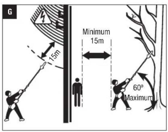
| Keep sufficient distance away from electrical power lines | To prevent electrocution, do not operate within 50 ft. (15m) of overhead electrical lines. Contact with or use near power lines may cause serious injury or electric shock resulting in death. | |
| Do Not Expose To Rain | Do not use in the rain or leave outdoors while it is raining. | |
| CE | CE | This product is in accordance with applicable EC directives. |
EN
EN
| WEEE | Waste electrical products should not be disposed of with household waste. Take to an authorized recycler. | |
| XX dB | Noise | Guaranteed sound power level. Noise emission to the environment according to the European community's Directive. |
| V Volt Voltage | ||
| mm Millimeter Length or | size | |
| cm Centimeter Length or | size | |
| in. Inch Length or size | ||
| kg Kilogram Weight | ||
| n0 | No Load Speed | Rotational speed, at no load |
| ... /min Per | Minute Revolutions per minute | |
| - | Direct Current | Type or a characteristic of current |
IMPORTANT SAFETY INSTRUCTIONS
WARNING! When using electric gardening appliances, basic safety precautions should always be followed to reduce the risk of fire, electric shock, and personal injury, including the following:
READ CAREFULLY BEFORE USE
KEEP FOR FUTURE REFERENCE
DANGER! Do not operate near electrical power lines. The unit has not been designed to provide protection from electric shock in the event of contact with overhead electric lines. Consult local regulations for safe distances from overhead electric power lines and ensure that the operating position is safe and secure before operating the tool.
POLE SAW SAFETY WARNINGS
-
Keep all parts of the body away from the saw chain when the pole saw is operating. Before you start the pole saw, make sure the saw chain is not contacting anything. A moment of inattention while operating pole saws may cause entanglement of your clothing or body with the chain.
-
Avoid unintentional contact with the stationary saw chain or guide bar rails. These can be very sharp. Always wear gloves and long pants or chaps when handling the pole saw, saw chain, or guide bar.
Always hold the pole saw with your one hand on the rear handle and your other hand on the front handle. Serious injury to the operator, helpers, and/or bystanders can result from one-handed operation. - Hold the power tool by insulated gripping surfaces only, because the saw chain may contact hidden wiring. Saw chains contacting a "live" wire may make exposed metal parts of the power tool "live" and could give the operator an electric shock.
- Wear safety glasses and hearing protection. Further protective equipment for head, hands, legs and feet is recommended. Adequate protective clothing will reduce personal injury by flying debris or accidental contact with the saw chain.
- Do not operate a pole saw in a tree. Operation of a pole saw while up in a tree may result in personal injury.
Always keep proper footing and operate the pole saw only when standing on fixed, secure and level surface. Slippery or unstable surfaces such as ladders may cause a loss of balance or control of the pole saw. - Never operate a pole saw that is damaged or improperly adjusted or that is not completely and securely assembled. Be sure that the saw chain stops moving when the trigger switch is released.
- Inspect the work piece for nails, wire, or other foreign objects prior to cutting.
- When cutting a limb that is under tension be alert for spring back. When the tension in the wood fibers is released the spring loaded limb may strike the operator and/or throw the pole saw out of control.
- Use extreme caution when cutting brush and saplings. The slender material may catch the saw chain and be whipped toward you or pull you off balance.
Aggressive or abusive cutting or misuse of the pole saw can cause premature bar, chain, and/or sprocket wear, as well as broken chain or bar, leading to kickback, chain throw or the ejection of material. -
Never use the guide bar as a lever. A bent guide bar can cause premature bar, chain, and/or sprocket wear, as well as a broken chain or bar, leading to kickback, chain throw or the ejection of material.
-
Carry the pole saw with two hands on the handles, with the pole saw switched off. When transporting or storing the pole saw always fit the guide bar cover. Proper handling of the pole saw will reduce the likelihood of accidental contact with the moving saw chain.
- Do not remove cut material or hold material to be cut when blades are moving. Make sure the switch is off when clearing jammed material. Saw chain continues to move after the switch is turned off. A moment of inattention while operating the pole pruner may result in serious personal injury.
- Follow instructions for lubricating, chain tensioning and changing accessories. Improperly tensioned or lubricated chain may either break or increase the chance for kickback. Keep cutting edge sharp and clean for best performance and to reduce the risk of injury.
- Keep handles dry, clean, and free from oil and grease. Greasy, oily handles are slippery causing loss of control.
Cut wood only. Do not use pole saw for purposes not intended. For example: do not use pole saw for cutting plastic, masonry or non-wood building materials. Use of the pole saw for operations different than intended could result in a hazardous situation. - Do not use the pole saw in bad weather conditions, especially when there is a risk of lightning. This decreases the risk of being struck by lightning.
-
Stop the motor and remove the battery pack whenever you leave the tool.
-
Store Idle Appliances Indoors. When not in use, appliances should be stored indoors in a dry and high or locked-up place with the battery pack removed, out of reach of children.
- Check Damaged Parts. Before further use of the product, a guard or other part that is damaged should be carefully checked to determine that it will operate properly and perform its intended function. Check for alignment of moving parts, binding of moving parts, breakage of parts, mounting, and any other condition that may affect its operation. A guard or other part that is damaged should be properly repaired or replaced by an authorized service center unless indicated elsewhere in this manual.
ADDITIONAL WARNINGS
- Do not charge the battery pack in rain, or in wet locations.
Use only with EGO's battery packs and chargers.
| BATTERY PACK CHARGER | |
| BA1120E, BA2240E, BA2800 | CH2100E |
| BA3360, BA4200 | CH5500E |
EN
The battery pack must be removed from the appliance before it is scrapped.
The battery shall be disposed of safely.
- Do not dispose of the battery in a fire. The cells may explode. Check with local codes for possible special disposal instructions.
- Do not open or mutilate the battery. Released electrolyte is corrosive and may cause damage to the eyes or skin. It may be toxic if swallowed.
CAUTION! The electrolyte is a dilute sulfuric acid that is harmful to the skin and eyes. It is electrically conductive and corrosive.
Exercise care in handling batteries in order not to short the battery with conducting materials such as rings, brackets, and keys. The battery or conductor may overheat and cause burns.
- Battery tools do not have to be plugged into an electrical outlet; therefore, they are always in operating condition. Be aware of possible hazards even when the tool is not operating. Take care when performing maintenance or service.
- Remove the battery pack before servicing, cleaning or removing material from the tool.
-
Replacement Parts - When servicing, use only identical EGO replacement parts. Use of any other accessory or attachment may increase the risk of injury.
-
Do not wash with a hose; avoid getting water in motor and electrical connections.
If situations occur that are not covered in this manual, use care and good judgment. Contact the EGO Service Center for assistance. - Save these instructions. Refer to them frequently and use them to instruct others who may use this tool. If you lend this tool to someone else, also lend these instructions to them to prevent misuse of the product and possible injury.
SAVE THESE INSTRUCTIONS
NOTE: SEE YOUR POWER HEAD OPERATOR'S MANUAL FOR ADDITIONAL SPECIFIC SAFETY RULES.
EN SPECIFICATIONS
| Guide Bar Length 250 mm | ||
| Chain Pitch 9.5 mm | ||
| Chain Gauge 1.1 mm | ||
| Saw Chain Type | 90PX040X (Oregon) | |
| Guide Bar Type | 104MLEA041 (Oregon) | |
| Chain Oil Tank Capacity 220 ml | ||
| Weight (with chain sheath) 1.89 kg | ||
| Measured sound power level LWA | 101.4 dB(A) K=2.36 dB(A) | |
| Sound pressure level at operator's ear LPA | 87.0 dB(A) K=3 dB(A) | |
| Guaranteed sound power level LWA (measured according to 2000/14/EC) | 104 dB(A) | |
| Valuation of vibration an: | Front-assist handle | 2.1 m/s2 K=1.5 m/s2 |
| Rear handle | 2.5 m/s2 K=1.5 m/s2 | |
The above parameters are tested and measured equipped with power head PH1400E.
The declared vibration total value has been measured in accordance with a standard test method and may be used for comparing one tool with another;
The declared vibration total value may also be used in a preliminary assessment of exposure.
NOTICE: The vibration emission during actual use of the power tool can differ from the declared value in which the tool is used; In order to protect the operator, user should wear gloves and ear protectors in the actual conditions of use.
PACKING LIST
| PART NAME QUANTITY | |
| Pole Saw Attachment 1 | |
| Chain Sheath 1 | |
| Dual-head Wrench 1 | |
| Operator's Manual 1 |
Recommended Bar and Chain for this Pole Saw
| PART NAME MODEL NUMBER | |
| Guide Bar AG1000 | |
| Saw Chain | AC1000 |
DESCRIPTION
KNOW YOUR POLE SAW ATTACHMENT (Fig. A)
- End Cap
- Soft Sleeve
- Pole-saw Shaft
- Dual-head Wrench
- Wrench Holder
- Cover-screw
- Chain-sprocket Cover
- Extension Pole (Optional, SOLD SEPARATELY)
- Chain Sheath
- Saw Chain
- Guide Bar
- Chain-tensioning Screw
- Oil-tank Cap
- Oil Tank
- Bucking Spikes
ASSEMBLY
WARNING: If any parts are damaged or missing, do not operate this product until the parts are replaced. Use of this product with damaged or missing parts could result in serious personal injury.
WARNING: Do not attempt to modify this product or create accessories not recommended for use with this pole saw. Any such alteration or modification is misuse and could result in a hazardous condition leading to possibly serious personal injury.
CONNECTING THE POLE SAW ATTACHMENT TO THE POWER HEAD
This pole saw attachment is designed for use with EGO 56V LITHIUM-ION Power Head PH1400E.
See "INSTALLING AN ATTACHMENT TO THE POWER HEAD" section in the power head PH1400E operator's manual.
CONNECTING THE EXTENSION POLE BETWEEN THE POWER HEAD AND THE POLE SAW ATTACHMENT (Optional)
The extension pole extends the cutting range. It should to be connected between the power head and the pole saw attachment.
Follow the process in the section "CONNECTING THE POLE SAW ATTACHMENT TO THE POWER HEAD "to install and secure the extension pole between the pole saw attachment and power head (Fig. C).
WARNING: Failure to secure the attachment and power head/extension pole as instructed above could result in serious injury or death.
WARNING: Never attach or adjust any attachment while the power head is running or with the battery installed. Failure to stop the motor and remove the battery may cause serious personal injury.
OPERATION
DANGER: Never cut near power lines, electric cords, or other electric sources. If the bar and chain jams on any electrical cord or line, DO NOT TOUCH THE BAR, CHAIN OR THE ALUMINUM POLE! THEY CAN BECOME ELECTRICALLY LIVE AND MAY BE VERY DANGEROUS.
Continue to hold the pole saw by the insulated rear handle or lay it down and away from you in a safe manner. Disconnect the electrical service to the damaged line or cord before attempting to free the bar and chain from the line or cord. Contact with the bar, chain, other conductive parts of the pole saw, or live electric cords or lines could result in death by electrocution or serious injury.
WARNING: Do not allow familiarity with this product to make you careless. Remember that a careless fraction of a second is sufficient to inflict serious injury.
WARNING: Always wear eye protection, along with hearing protection. Failure to do so could result in objects being thrown into your eyes and other possible serious injuries.
Before each use, inspect the entire product for damaged, missing, or loose parts such as screws, nuts, bolts, caps, etc. Tighten securely all fasteners and caps and do not operate this product until all missing or damaged parts are replaced.
WARNING: To prevent serious personal injury, remove the battery pack from the tool before servicing, cleaning, changing attachments or removing material from the unit.
APPLICATIONS
You may use this product for the purpose listed below:
Limbing
Pruning
NOTICE: The tool is to be used only for its prescribed purpose. Any other use is deemed to be a case of misuse.
FILLING OILTANK WITH BAR AND CHAIN LUBRICANT
WARNING: Do not smoke or bring any fire or flame near the oil or the pole saw. Oil may spill and cause a fire.
NOTICE: The pole saw is not filled with oil at the time of purchase. It is essential to fill the tank with chain oil before use. Chain life and cutting capacity depend on optimum lubrication. The chain is automatically lubricated with chain oil during operation. Oil level should also be checked after every 20 minutes of use and refilled as needed.
- Remove the battery pack from the power head.
- Clean the oil tank cap and the area around it to ensure that no dirt falls into the oil tank.
- Place the pole saw attachment upright and rotate the oil tank cap counterclockwise to remove it (Fig. D).
- Carefully pour the bar and chain oil into the tank until it fills to the tank neck. Be careful not to let the oil spill from the opening. Wipe off any excess oil and close the oil tank cap.
NOTICE:
Use ORIGO and chain oil for best results. It is specially designed to provide low friction and faster cuts.
- Do not use dirty, used or other contaminated oils. Damage may occur to the bar or chain.
PREPARATION FOR CUTTING (Fig. B)
Refer to "Important Safety Instructions" earlier in this manual for appropriate safety equipment.
- Lift the tip of the guide bar to check for any sagging in the chain. The chain is correctly tensioned when there is no sag on the underside of the guide bar and the chain is snug, but it can be turned by hand without binding. If the tension requires adjustment, refer to the "REPLACING THE BAR AND CHAIN" section in the MAINTENANCE section of this manual for adjustment instructions.
- Check the tension of the cover screw before use. If it is loose, securely tighten the cover screw by turning it clockwise.
- Check the sharpness of cutting teeth on the saw chain and make sure the chain is well lubricated.
EN
Wear non-slip gloves for maximum grip and protection.LIMBING AND PRUNING
Never stand directly under the limb you are cut ting.
Make sure that you have a secure and balanced footing.
Watch out for obstacles such as tree stumps, roots and ditches, which could cause you to trip or stumble.
- Maintain a proper grip on the unit whenever the motor is running. Hold the unit firmly with both hands.
- For safe and better operation, put on the shoulder strap across the shoulder. Adjust the shoulder strap into a comfortable operating position. Following the instructions in the section "MOUNTING THE SHOULDER STRAP" in PH1400E operator's manual to attach the shoulder strap onto the power head.
WARNING: The shoulder strap is also a quick release mechanism in hazardous situation. When an emergency occurs, take it off your shoulder immediately, no matter what way the strap is in.
TO START/STOP THE TOOL
See "STARTING/STOPPING THE POWER HEAD" section in the power head PH1400E operator's manual.
BASIC CUTTING PROCEDURE (Fig. E & F)
Follow the steps below to prevent damage to tree or shrub bark. Do not use a back-and-forth sawing motion.
- Make a shallow first cut (1/4 of limb diameter) on the underside of the limb close to the main limb or trunk.
- Make a second cut from the top side of the limb outboard from the first cut. Continue the cut through the limb until the limb separates from the tree. Be prepared to balance the weight of the tool when the limb falls.
- Make a final cut close to trunk.
NOTICE: For second and final cuts (from top of limb or branch), hold the bucking spikes against the limb being cut (Fig. F). This will help steady the limb and make it easier to cut with light downward pressure. If you force the cut, damage to the bar, chain, or motor can result in
4. Release the trigger on the power head as soon as the cut is completed.
NOTICE: Failure to follow proper cutting procedures will result in the bar and chain binding and becoming pinched or trapped in the limb. If this should happen:
- Stop the motor and remove the battery pack.
- If the limb can be reached from the ground, lift the limb while holding the saw. This should release the "pinch" and free the saw.
- If the saw is still trapped, call a professional for assistance.
This pole saw attachment is designed for trimming small branches and limbs up to 20cm in diameter. For best results, observe the following precautions.
- Plan the cut carefully. Be aware of the direction in which the branch will fall.
WARNING: Branches may fall in unexpected directions. Do not stand directly under the branch being cut.
- The most typical cutting application is to position the unit at an angle of 60^ or less (Fig. G). As the angle of the pole saw shaft to the ground increases, the difficulty of making the first cut (from the underside of limb) increases.
- Remove long branches in several stages.
- Cut lower branches first to allow the top branch es more room to fall.
- Work slowly, keeping both hands on the saw with a firm grip. Maintain secure footing and balance.
- Do not cut from a ladder; this is extremely dangerous. Leave such operations for professionals.
- Do not make the flush cut next to the main limb or trunk until you have cut off much of limb to reduce the weight. Following proper cutting procedures will prevent stripping the bark from the main member.
- Do not use the pole saw for felling or bucking.
- To prevent electrocution, do not operate within 15m of overhead electrical lines and keep bystanders at least 15m away (Fig. G).
MAINTENANCE
WARNING: Before inspecting, cleaning or servicing the unit, stop the motor, wait for all moving parts to stop, and remove the battery pack. Failure to follow these instructions can result in serious personal injury or property damage.
WARNING: When servicing, use only identical replacement parts. Use of any other parts can create a hazard or cause product damage. To ensure safety and reliability, all repairs, other than the items listed in these maintenance instructions, should be performed by a qualified service technician.
GENERAL MAINTENANCE
Avoid using solvents when cleaning plastic parts. Most plastics are susceptible to damage from various types of commercial solvents and may be damaged by their use. Use clean cloths to remove dirt, dust, oil, grease, etc.
CLEAN THE UNIT
After each use, remove the battery and clean debris from the chain and guide bar with a soft brush. Wipe the pole saw surface with a clean cloth moistened with a mild soap solution.
- Remove the chain-sprocket cover, and then use a soft brush to remove debris from the guide bar, saw chain, sprocket and chain-sprocket cover.
Always clean out wood chips, saw dust, and dirt from the guide bar groove when replacing the saw chain.
NOTICE: Do not use any strong detergents on the plastic housing or the handle. They can be damaged by certain aromatic oils such as pine and lemon.
REPLACING THE BAR AND CHAIN
WARNING: Never touch or adjust the chain while the motor is running. The saw chain is very sharp; always wear protective gloves when performing maintenance to the chain.
NOTICE: When replacing the guide bar and chain, always use the specified bar and chain combination listed in the "Recommended Bar and Chain for this Pole Saw" section.
Disassembling the Worn Bar and Chain
- Remove the battery, allow the pole saw to cool and tighten the oil tank cap.
- Position the pole saw attachment on its side with the chain-sprocket cover is facing upwards.
- Wear gloves. Using the dual-head wrench provided, loosen the cover screw to remove the screw and the chain-sprocket cover. Clean the chain-sprocket cover with a dry cloth and save it for reassembly (Fig. H).
- Remove the bar and chain from the mounting surface. Remove the worn chain from the bar.
NOTICE: If there is difficulty in removing the bar and chain from the mounting surface, place the pole saw upright, with one hand support the bar, to loosen the chain-tensioning screw counterclockwise with the other hand (Fig. I) and then remove the bar with the chain.
NOTICE: This is a good time to inspect the drive sprocket for excessive wear or damage.
Assembling the New Bar and Chain
- Lay the new saw chain in a loop on a flat surface and straighten any kinks (Fig. J).
- Place the chain drive links into the guide bar groove. Position the chain so there is a loop at the back of the guide bar (Fig. K).
Fig. K parts description see below:
K-1 Chain Drive Links K-2 Guide-bar Groove
- Hold the chain in position on the guide bar and place the loop around the sprocket of the pole saw.
NOTICE: Small directional arrows are engraved in the saw chain. Another directional arrow is molded into the tool body (Fig. L). When looping the saw chain onto the sprocket, make sure that the direction of the arrows on the saw chain will CORRESPOND to the direction of the arrow on the tool body. If they face in opposite directions, turn over the saw chain and guide bar assembly (Fig. M).
Fig. L parts description see below:
| L-1 Sprocket |
| L-2 Tension-adjusting Pin |
| L-3 Alignment Bulges |
| L-4 Chain-tensioning Screw |
| L-5 Guide-bar Slot |
- Place the guide bar on the mounting surface by sliding the guide bar slot over the alignment bulges, making sure that the tension adjusting pin is inserted in the lower hole in the tail of the bar (Fig. L).
NOTICE: If there is difficulty in inserting the tension adjusting pin into the hole, adjust the chain-tensioning screw properly until the tension adjusting pin is located exactly in the hole. - Replace the chain-sprocket cover and the cover screw. Slightly tighten them.
- Remove all the slack from the chain by turning the chain-tensioning screw clockwise until the chain seats snugly against the guide bar with the drive links in the guide bar groove and lift the tip of the guide bar to check for sag. Release the tip of the guide bar and turn the chain-tensioning screw once clockwise. Repeat this process until the sag is eliminated (Fig. N).
- Hold the tip of the guide bar up and tighten the chain-sprocket-cover screw securely.
NOTICE: To extend the guide bar life, invert the bar occasionally.
NOTICE: If chain is too tight, it will not rotate. Loosen the chain-sprocket-cover screw slightly and turn the tensioning screw 1/4 turn counterclockwise. Lift the tip of the guide bar and retighten the chain-sprocket-cover screw securely. Assure that the chain will rotate without binding.
EN
ADJUSTING THE CHAIN TENSION
CAUTION: The saw chain must be properly tensioned before using.
- Stop the motor and remove the battery pack before adjusting the chain tension.
- Loosen the cover screw to finger tight.
- Turn the chain-tensioning screw clockwise to tension the chain. See the "REPLACING THE BAR AND CHAIN" section in this manual for additional information.
A cold chain is correctly tensioned when there is no slack on the underside of the guide bar and the chain is snug, but it can be turned by hand without binding. The chain must be re-tensioned whenever the flats on the drive links do not sit in the bar groove (Fig. 0).
During normal saw operation, the temperature of the chain will increase. The drive links of a correctly tensioned warm chain will hang approximately 1.3mm out of the bar groove (Fig.P).
NOTICE: New chains tend to stretch; check chain tension frequently and tension as required.
NOTICE: A chain tensioned while it is warm may be too tight upon cooling. Check the cold tension before next use.
The transmission gears in the gear case need be lubricated periodically with gear grease. Check the gear case grease level about every 50 hours of operation by removing the sealing screw on the side of the case.
If no grease can be seen on the flanks of the gear, follow the steps below to fill with gear grease up to 3/4 capacity.
Do not completely fill the transmission gears.
- Position the pole saw attachment on its side with sealing screw facing upwards (Fig. Q).
- Use the dual-head wrench provided to loosen and remove the injection screw.
- Use a grease syringe (not included) to inject some grease into the screw hole; do not exceed 3/4 capacity.
- Tighten the sealing screw after injection.
SPROCKET IN GUIDE BAR LUBRICATION
The guide bar has a sprocket at its tip. It must be lubricated weekly with chain oil injected into the lubricating hole by a grease syringe (not included) to extend the guide bar life (Fig. R). Turn the guide bar and check that the lubrication holes and chain groove are free from impurities.
Fig. R parts description see below:
R-1 Lubricating Hole
R-2 Sprocket in Guide-bar Tip
TRANSPORTING AND STORING
- Do not store or transport the pole saw attachment when it is running. Always remove the battery pack before storing or transporting.
- Always place the guide bar sheath on the guide bar and chain before storing or transporting the pole saw attachment. Use caution to avoid the sharp teeth of the chain.
- Clean the pole saw thoroughly before storing. Store the pole saw indoors, in a dry place that is locked and/or inaccessible to children and keep away from corrosive agents such as garden chemicals and de-icing salts.
- If the pole saw attachment is removed from the power head and stored separately, fit the end cap on the attachment shaft to avoid dirt getting into the coupler.
Protecting the environment

Do not dispose of electrical equipment, battery charger and batteries/ rechargeable batteries into household waste!
According to the European law 2012/19/EU, electrical and electronic equipment that is no longer usable, and according to the European law 2006/66/EC, defective or used battery packs/batteries, must be collected separately.
If electrical appliances are disposed of in landfills or dumps, hazardous substances can leak into the groundwater and get into the food chain, damaging your health and well-being.
EC DECLARATION OF CONFORMITY

EN
We, EGO EUROPE GMBH
Declare that the product 56V lithium-ion cordless pole saw attachment PSA1000, equipped with power head PH1400E.
Complies with the essential health and safety requirements of the following Directives:
2006/42/EC, 2014/30/EU, 2011/65/EU, 2000/14/EC
Standards and technical specifications referred to:
EN ISO 11680-1, EN 60745-1, EN 55014-1, EN 55014-2
Measured Sound Power Level: 101.4 dB(A),
Guaranteed Sound Power Level: 104 dB(A)
Dong Jiong.
Peter Melrose Dong Jianxun
Managing Director of
EGO Europe GmbH Chervon
Quality Manager of
(Authorized representative for CHERVON and responsible for technical documentation)
01/12/2016
EN TROUBLESHOOTING
| PROBLEM CAUSE SOLUTION | ||
| Motor does not run. | The battery pack is not attached to the pole saw. No electrical contact between the saw and battery. The battery pack is depleted. The lock-off button is not depressed before pressing the trigger. The battery pack or power head is too hot. Saw chain is bound in the wood. Debris in bar groove. Debris in chain-sprocket cover. | Attach the battery pack to the pole saw. Remove battery, check contacts and reinstall the battery pack. Charge the battery pack. Press down the lock-off lever and hold it, then depress the trigger to turn on the pole saw. Allow the battery pack or power head to cool until the temperature drops below 152°F (67°C). Release the trigger, remove the saw chain and guide bar from the wood, then restart the pole saw. Press the saw chain against the wood, move the pole saw back and forth to discharge the debris. Remove battery pack, then remove chain-sprocket cover and clean out debris. |
| Motor runs, but chain does not rotate. | Chain does not engage drive sprocket. | Remove the battery pack and reinstall the chain, making sure that the drive links on the chain are fully seated on the sprocket. |
| Pole saw does not cut properly. | Insufficient chain tension. Dull chain. Chain installed backwards. Worn chain. Dry or excessively stretched chain. Chain not in bar groove. | Remove the battery pack and readjust the chain tension, following the section "ADJUSTING THE CHAIN TENSION". Sharpen the chain cutters by a qualified service technician. Remove the battery pack and reinstall the saw chain, following the section "REPLACING THE BAR AND CHAIN". Remove the battery pack and replace the chain following the section "REPLACING THE BAR AND CHAIN". Check the oil level. Refill the oil tank if necessary. Remove the battery pack and reinstall the saw chain, following the section "REPLACING THE BAR AND CHAIN". |
| Bar and chain running hot and smoking. | Check chain tension for over tightened condition. Chain oil tank is empty. Debris in guide bar groove. | Remove the battery pack and re-tension the saw chain; see the section "ADJUSTING THE CHAIN TENSION". Filling bar and chain lubricant. Clear the debris in the groove. |
WARRANTY
EGO WARRANTY POLICY
Please visit the website egopowerplus.com for full terms and conditions of the EGO Warranty policy.
2006/42/CE, 2014/30/UE, 2011/65/UE, 2000/14/CE
Normes et specifications techniques vises:
EN ISO 11680-1, EN 60745-1, EN 55014-1, EN 55014-2
2006/42/CE, 2014/30/UE, 2011/65/UE, 2000/14/CE
Normas y espécificaciones技术水平s:
EN ISO 11680-1, EN 60745-1, EN 55014-1, EN 55014-2
HET APPARAAT SCHOONMAKEN
RENGORING AF APPARATET
- After haverbrug aftages batteriet, og kaden og savsvaerdet rengores for materiale med en blod børste. Tør stangsavens overflade af med en ren klud, fugtet med en mild saebeoplosning.
Fjern daekslet til kaedetandhjulet, og brug derefter en blod borste til at fjerne snavs fra svardet, savkaeden, tandhjulet og daekslet til tandhjulet.
Rengør altid rillen pa savsvaerdet for treaflis, savsmuld og skidt, inden savkaeden saettes pa.
GENERELT VEDLIKEHOLD
| PROBLEM ÅRSAK LÖSNING | ||
| Motoren kjøreren次会议 | ■ Batteripakken er ikke installiert.■ Ingen elektrisk kontakt mellem sagen og batteriet.■ Batteripakken er tom.■ Låseknappen er ikke trykkeinn for ør du trykkepaa utloserbryteren.■ Batteripakken eller verktøyhodet er for opphetet.Sagkjedet sitter fast i treet.Rusk i sverdspotet.Rusk i tannlenkedekslet. | ■ Installer batteripakken.■ larnjern batteriet, sjekk kontakter og installer batteripakken igjen.Lad opp batteripakken.Trykk ned læsespaken og hold deninne, og trykk deretter paa utloseren for ø slå pa stangsagen.La batteripakken erlor verktøyhodet kjole seg ned til temperaturen kommer under 67 °C (152 °F).Slipp utloseren; ta bort sagkjede og sverd fra treet, og start deretter sagen på nytt.Trykk sagkjedet mot treet og beveg sagen frem og tilbake for ø bil kvitt rusket.Ta ut batteripakken, fjern deretter tannlenkedekslet og rens ut rusket. |
| Motoren gårn men kjeted gårn参加会议 | ■ Kjeted tar ikke tak i drivhjulet. | ■ Ta ut batteripakken og installer kjeted på nytt. Vær papiasselig med at kjeteds drivlenker siter godt på kjetehjulet. |
| Stangsagen kapper ikke ordentlig. | ■ Utilstrekkelig kjerestramming.Ni Søvt kjeede.Kjeted er installment baklengs.Slitt kjeede.Tørller overstrukket kjeede.Kjeted er/DDKjeted er/DDKjeted er/DDKjeted er/DDKjeted er/DDKjeted er/DDKjeted er/DDKjeted er/DDKjeted er/DDKjeted er/DDKjeted er/DDKjeted er/DDKjeted er/DDKjeted er/DDKjeted er/DDKjeted er/DDKjeted er/DDKjeted er/DDKjeted er/DDKjeted er/DDKjeted er/DDKCjeted er/DDKCjeted er/DDKCjeted er/DDKCjeted er/DDKCjeted er/DDKCjeted er/DDKCjeted er/DDKCjeted er/DDKCjeted er/DDKCjeted er/DDKCjeted er/DDKCjeted er/DDKCjeted er/DDKCjeted er/DDKCjeted er/DDKCjeted er/DDKCjeted er/DDKCjeted er/DDKCjeted er/DDKCjeted er/DDKjeted er/DDKCjeted er/DDKCjeted er/DDKCjeted er/DDKCjeted er/DDKCjeted er/DDKCjeted er/DDKCjeted er/DDKCjeted er/DDKCjeted er/DDKCjeted er/DDKCjeted er/DDKCjeted er/DDKCjeted er/DDKCjeted er/DDKCjeted er/DDKCjeted er/DDKCjeted er/DDKCjeted er/DDKjeted er/DDKjeted er/DDKCjeted er/DDKCjeted er/DDKCjeted er/DDKCjeted er/DDKCjeted er/DDKCjeted er/DDKCjeted er/DDKCjeted er/DDKCjeted er/DDKCjeted er/DDKCjeted er/DDKCjeted er/DDKCjeted er/DDKCjeted er/DDKCjeted er/DDKCjeted er/DDKCjeted er/DDKjeted er/DDKCjeted er/DDKjeted er/DDKCjeted er/DDKCjeted er/DDKCjeted er/DDKCjeted er/DDKCjeted er/DDKCjeted er/DDKCjeted er/DDKCjeted er/DDKCjeted er/DDKCjeted er/DDKCjeted er/DDKCjeted er/DDKCjeted er/DDKCjeted er/DDKCjeted er/DDKCjeted er/DDKCjeted er/DDKjeted er/DDKjeted er/DDKjeted er/DDKCjeted er/DDKCjeted er/DDKCjeted er/DDKCjeted er/DDKCjeted er/DDKCjeted er/DDKCjeted er/DDKCjeted er/DDKCjeted er/DDKCjeted er/DDKCjeted er/DDKCjeted er/DDKCjeted er/DDKCjeted er/DDKCjeted er/DDKCjeted er/DDKjeted er/DDKCjeted er/DDKCjeted er/DDKjeted er/DDKCjeted er/DDKCjeted er/DDKCjeted er/DDKCjeted er/DDKCjeted er/DDKCjeted er/DDKCjeted er/DDKCjeted er/DDKCjeted er/DDKCjeted er/DDKCjeted er/DDKCjeted er/DDKCjeted er/DDKCjeted er/DDKCjeted er/DDKCjeted er/DDKjeted er/DDKCjeted er/DDKjeted er/DDKjeted er/DDKCjeted er/DDKCjeted er/DDKCjeted er/DDKCjeted er/DDKCjeted er/DDKCjeted er/DDKCjeted er/DDKCjeted er/DDKCjeted er/DDKCjeted er/DDKCjeted er/DDKCjeted er/DDKCjeted er/DDKCjeted er/DDKCjeted er/DDKCjeted er/DDKjeted er/DDKjeted er/DDKCjeted er/DDKjeted er/DDKCjeted er/DDKCjeted er/DDKCjeted er/DDKCjeted er/DDKCjeted er/DDKCjeted er/DDKCjeted er/DDKCjeted er/DDKCjeted er/DDKCjeted er/DDKCjeted er/DDKCjeted er/DDKCjeted er/DDKCjeted er/DDKCjeted er/DDKCjeted er/DDKjeted er/DDKjeted er/DDKjeted er/DDKjeted er/DDKCjeted er/DDKCjeted er/DDKCjeted er/DDKCjeted er/DDKCjeted er/DDKCjeted er/DDKCjeted er/DDKCjeted er/DDKCjeted er/DDKCjeted er/DDKCjeted er/DDKCjeted er/DDKCjeted er/DDKCjeted er/DDKCjeted er/DDKjeted er/DDKCjeted er/DDKCjeted er/DDKCjeted er/DDKjeted er/DDKCjeted er/DDKCjeted er/DDKCjeted er/DDKCjeted er/DDKCjeted er/DDKCjeted er/DDKCjeted er/DDKCjeted er/DDKCjeted er/DDKCjeted er/DDKCjeted er/DDKCjeted er/DDKCjeted er/DDKCjeted er/DDKCjeted er/DDKjeted er/DDKCjeted er/DDKCjeted er/DDKjeted er/DDKjeted er/DDKCjeted er/DDKCjeted er/DDKCjeted er/DDKCjeted er/DDKCjeted er/DDKCjeted er/DDKCjeted er/DDKCjeted er/DDKCjeted er/DDKCjeted er/DDKCjeted er/DDKCjeted er/DDKCjeted er/DDKCjeted er/DDKCjeted er/DDKjeted er/DDKCjeted er/DDKjeted er/DDKCjeted er/DDKjeted er/DDKCjeted er/DDKCjeted er/DDKCjeted er/DDKCjeted er/DDKCjeted er/DDKCjeted er/DDKCjeted er/DDKCjeted er/DDKCjeted er/DDKCjeted er/DDKCjeted er/DDKCjeted er/DDKCjeted er/DDKCjeted er/DDKCjeted er/DDKjeted er/DDKCjeted er/DDKjeted er/DDKjeted er/DDKjeted er/DDKCjeted er/DDKCjeted er/DDKCjeted er/DDKCjeted er/DDKCjeted er/DDKCjeted er/DDKCjeted er/DDKCjeted er/DDKCjeted er/DDKCjeted er/DDKCjeted er/DDKCjeted er/DDKCjeted er/DDKCjeted er/DDKCjeted er/DDKjeted er/DDKjeted er/DDKCjeted er/DDKCjeted er/DDKjeted er/DDKCjeted er/DDKCjeted er/DDKCjeted er/DDKCjeted er/DDKCjeted er/DDKCjeted er/DDKCjeted er/DDKCjeted er/DDKCjeted er/DDKCjeted er/DDKCjeted er/DDKCjeted er/DDKCjeted er/DDKCjeted er/DDKCjeted er/DDKjeted er/DDKjeted er/DDKCjeted er/DDKjeted er/DDKjeted er/DDKCjeted er/DDKjeted er/DDKCjeted er/DDKjeted er/DDKCjeted er/DDKjeted er/DDKCjeted er/DDKjeted er/DDKCjeted er/DDKjeted er/DDKCjeted er/DDKjeted er/DDKCjeted er/DDKjeted er/DDKCjeted er/DDKjeted er/DDKCjeted er/DDKjeted er/DDKCjeted er/DDKjeted er/DDKjeted er/DDKCjeted er/DDKjeted er/DDKCjeted er/DDKjeted er/DDKCjeted er/DDKjeted er/DDKCjeted er/DDKjeted er/DDKCjeted er/DDKjeted er/DDKCjeted er/DDKjeted er/DDKCjeted er/DDKjeted er/DDKCjeted er/DDKCjeted er/DDKjeted er/DDKCjeted er/DDKjeted er/DDKCjeted er/DDKjeted er/DDKCjeted er/DDKjeted er/DDKCjeted er/DDKjeted er/DDKCjeted er/DDKjeted er/DDKCjeted er/DDKjeted er/DDKCjeted er/DDKjeted er/DDKCjeted er/DDKjeted er/DDKCjeted er/DDKCjeted er/DDKjeted er/DDKCjeted er/DDKCjeted er/DDKjeted er/DDKCjeted er/DDKjeted er/DDKCjeted er/DDKjeted er/DDKCjeted er/DDKjeted er/DDKCjeted er/DDKjeted er/DDKCjeted er/DDKjeted er/DDKCjeted er/DDKjeted er/DDKCjeted er/DDKjeted er/DDKjeted er/DDKCjeted er/DDKjeted er/DDKjeted er/DDKCjeted er/DDKjeted er/DDKCjeted er/DDKjeted er/DDKCjeted er/DDKjeted er/DDKCjeted er/DDKjeted er/DDKCjeted er/DDKjeted er/DDKCjeted er/DDKjeted er/DDKCjeted er/DDKCjeted er/DDKjeted er/DDKCjeted er/DDKjeted er/DDKCjeted er/DDKCjeted er/DDKjeted er/DDKCjeted er/DDKjeted er/DDKCjeted er/DDKjeted er/DDKCjeted er/DDKjeted er/DDKCjeted er/DDKjeted er/DDKCjeted er/DDKjeted er/DDKCjeted er/DDKjeted er/DDKjeted er/DDKCjeted er/DDKjeted er/DDKCjeted er/DDKjeted er/DDKjeted er/DDKCjeted er/DDKjeted er/DDKCjeted er/DDKjeted er/DDKCjeted er/DDKjeted er/DDKCjeted er/DDKjeted er/DDKCjeted er/DDKjeted er/DDKCjeted er/DDKjeted er/DDKCjeted er/DDKCjeted er/DDKjeted er/DDKjeted er/DDKCjeted er/DDKjeted er/DDKCjeted er/DDKjeted er/DDKCjeted er/DDKjeted er/DDKCjeted er/DDKjeted er/DDKCjeted er/DDKjeted er/DDKCjeted er/DDKjeted er/DDKCjeted er/DDKjeted er/DDKCjeted er/DDKjeted er/DDKjeted er/DDKCjeted er/DDKCjeted er/DDKjeted er/DDKCjeted er/DDKjeted er/DDKCjeted er/DDKjeted er/DDKCjeted er/DDKjeted er/DDKCjeted er/DDKjeted er/DDKCjeted er/DDKjeted er/DDKCjeted er/DDKjeted er/DDKCjeted er/DDKjeted er/DDKCjeted er/DDKCjeted er/DDKjeted er/DDKjeted er/DDKCjeted er/DDKjeted er/DDKjeted er/DDKCjeted er/DDKjeted er/DDKCjeted er/DDKjeted er/DDKCjeted er/DDKjeted er/DDKCjeted er/DDKjeted er/DDKCjeted er/DDKjeted er/DDKCjeted er/DDKjeted er/DDKjeted er/DDKCjeted er/DDKjeted er/DDKCjeted er/DDKjeted er/DDKCjeted er/DDKCjeted er/DDKjeted er/DDKCjeted er/DDKjeted er/DDKCjeted er/DDKjeted er/DDKCjeted er/DDKjeted er/DDKCjeted er/DDKjeted er/DDKCjeted er/DDKjeted er/DDKCjeted er/DDKCjeted er/DDKjeted er/DDKCjeted er/DDKjeted er/DDKCjeted er/DDKjeted er/DDKjeted er/DDKCjeted er/DDKjeted er/DDKCjeted er/DDKjeted er/DDKCjeted er/DDKjeted er/DDKCjeted er/DDKjeted er/DDKCjeted er/DDKjeted er/DDKCjeted er/DDKjeted er/DDKjeted er/DDKCjeted er/DDKjeted er/DDKjeted er/DDKCjeted er/DDKjeted er/DDKjeted er/DDKCjeted er/DDKjeted er/DDKCjeted er/DDKjeted er/DDKCjeted er/DDKjeted er/DDKCjeted er/DDKjeted er/DDKCjeted er/DDKjeted er/DDKCjeted er/DDKjeted er/DDKjeted er/DDKjeted er/DDKCjeted er/DDKjeted er/DDKCjeted er/DDKjeted er/DDKCjeted er/DDKjeted er/DDKCjeted er/DDKjeted er/DDKCjeted er/DDKjeted er/DDKCjeted er/DDKjeted er/DDKCjeted er/DDKjeted er/DDKCjeted er/DDKjeted er/DDKCjeted er/DDKCjeted er/DDKCjeted er/DDKjeted er/DDKCjeted er/DDKCjeted er/DDKjeted er/DDKCjeted er/DDKCjeted er/DDKjeted er/DDKCjeted er/DDKCjeted er/DDKjeted er/DDKCjeted er/DDKjeted er/DDKCjeted er/DDKjeted er/DDKCjeted er/DDKjeted er/DDKCjeted er/DDKjeted er/DDKCjeted er/DDKjeted er/DDKCjeted er/DDKCjeted er/DDKjeted er/DDKCjeted er/DDKCjeted er/DDKjeted er/DDKCjeted er/DDKCjeted er/DDKjeted er/DDKCjeted er/DDKCjeted er/DDKjeted er/DDKCjeted er/DDKCjeted er/DDKjeted er/DDKCjeted er/DDKCjeted er/DDKCjeted er/DDKCjeted er/DDKCjeted er/DDKCjeted er/DDKCjeted er/DDKCjeted er/DDKCjeted er/DDKCjeted er/DDKCjeted er/DDKCjeted er/DDKCjeted er/DDKjeted er/DDKCjeted er/DDKCjeted er/DDKCjeted er/DDKCjeted er/DDKCjeted er/DDKjeted er/DDKCjeted er/DDKCjeted er/DDKCjeted er/DDKCjeted er/DDKCjeted er/DDKCjeted er/DDKCjeted er/DDKCjeted er/DDKCjeted er/DDKCjeted er/DDKCjeted er/DDKCjeted er/DDKCjeted er/DDKjeted er/DDKCjeted er/DDKCjeted er/DDKjeted er/DDKCjeted er/DDKCjeted er/DDKjeted er/DDKCjeted er/DDKCjeted er/DDKCjeted er/DDKCjeted er/DDKCjeted er/DDKCjeted er/DDKCjeted er/DDKCjeted er/DDKCjeted er/DDKCjeted er/DDKjeted er/DDKCjeted er/DDKCjeted er/DDKCjeted er/DDKCjeted er/DDKCjeted er/DDKCjeted er/DDKCjeted er/DDKCjeted er/DDKjeted er/DDKCjeted er/DDKCjeted er/DDKCjeted er/DDKCjeted er/DDKCjeted er/DDKCjeted er/DDKCjeted er/DDKCjeted er/DDKCjeted er/DDKCjeted er/DDKjeted er/DDKCjeted er/DDKCjeted er/DDKCjeted er/DDKCjeted er/DDKCjeted er/DDKjeted er/DDKCjeted er/DDKCjeted er/DDKjeted er/DDKCjeted er/DDKCjeted er/DDKCjeted er/DDKCjeted er/DDKCjeted er/DDKCjeted er/DDKCjeted er/DDKCjeted er/DDKCjeted er/DDKCjeted er/DDKjeted er/DDKCjeted er/DDKCjeted er/DDKjeted er/DDKCjeted er/DDKCjeted er/DDKCjeted er/DDKCjeted er/DDKCjeted er/DDKjeted er/DDKCjeted er/DDKCjeted er/DDKCjeted er/DDKCjeted er/DDKCjeted er/DDKCjeted er/DDKCjeted er/DDKCjeted er/DDKCjeted er/DDKCjeted er/DDKjeted er/DDKCjeted er/DDKCjeted er/DDKjeted er/DDKCjeted er/DDKCjeted er/DDKjeted er/DDKCjeted er/DDKCjeted er/DDKjeted er/DDKCjeted er/DDKCjeted er/DDKjeted er/DDKCjeted er/DDKjeted er/DDKCjeted er/DDKjeted er/DDKCjeted er/DDKjeted er/DDKCjeted er/DDKCjeted er/DDKjeted er/DDKCjeted er/DDKjeted er/DDKCjeted er/DDKjeted er/DDKCjeted er/DDKjeted er/DDKCjeted er/DDKjeted er/DDKjeted er/DDKCjeted er/DDKjeted er/DDKCjeted er/DDKjeted er/DDKCjeted er/DDKjeted er/DDKjeted er/DDKjeted er/DDKjeted er/DDKjeted er/DDKjeted er/DDKjeted er/DDKjeted er/DDKjeted er/DDKjeted er/DDKjeted er/DDKjeted er/DDKjeted er/DDKjeted er/DDKjeted er/DDKjeted er/DDKjeted er/DDKjeted er/DDKjeted er/DDKA: | |
GARANTI
EGOGARANTIREGLER
Besk nettsiden egopowerplus.com for a se fullstendige vilkar og betingelser for EGO-garantiireglene.
ПОЧТАЕ BCE ИНСТРУКЦИ!

CM.PYKOBODCTBOIOJIb3OBATEJI
A OctaToUHbI pNcK! IIOJAM C
IMnHaHTnoPoBaHHbIMN 3NeKtpoHbIMn yCTPOINCTBaMn (Haep KApDIOCTMMyIaTOpAMn) HeOxOIMNO npOKOHcyIbTnpoBaTcBcA CLeaUIM BpaOM, IpexKe demCnOJIb3OBaTB daHbI mHCTpyMeNT. IcNoJIb3OBaHne 3NEKTOO6OpOyOBaHnB HENOCpeCDtBeHHoB 6NI30CTNOT KAPINOCTMMyIaTOpa MoKET cTaB pnuHHO nepe6oEB B pa6oTE INN OTKa3a KaPINOCTMMyIaTOpa.
BHIMAHNE!Ia oecneeyehn6e0naoctn nHaedxHOn 3KcNpyatauHnHCTpyMeHTa BCE peMOHTbIe paobTbIOJXHbBbINOJIHrTBcCnAmn KBaIIINpOBaHHbIX CneuaJIInCTOB.
PPEyIPEXDAIOUNE CIMBOIbI
DaHHbIe CmBONbl npedHa3HauHeHdI npnBLeueHnBaWero BmMaHnK pKaTOpam PnCKa. PeKOMEnyETc03hakomntbcra n pa3o6paTbcra CO BCEMnPepynpeXdaOuIMN CmBOnaMn N OraCHeHnMn K Hm.PpeynpeXdaOuNE CmBOnbl He HeITpAn3yOT PaKToPbPnCKa.Yka3AHn I npdynpexDeHnne He MOrY 3aMeHnTBNaEaUme MebppeoCTopoxHOCTn.
BHUMAHNE!PexJe cemNcNoIb3OBAbTHNCTpyMeHT,IpouHtaiTe n pa36epntecb CO BCEMnPpABNJAMn TEXHNKn 6e3oNaCHOCTn, npBBeDeHHbIMB DAHHOM pyKOBOdCTBE NOJb3OBaTeR,BKNIOyA BCEnpDynpExdaIOUne CNMBOnbl, TAKHe KAc (ONACHO),《BHUMAHNE》N《OCTOPOXHO》.HecO6JIIOdeHyeKa3aHm, npBBeDEHHbIX HnKe,MOxET pNpBeCTN KnopaxHeHIO 3JIeKtpueckkM TOKOM, BO3ropaHIO N/INNCpeB3HbIM TpaBMam.
3HAUHNE CUMBOJOB
CIMBOI BOCKJIINUATEJIbHOrO 3HAKA B
TPEYTOJIbHNIke:O3HaayeET

HIMAHNE!IcnoIb3ObaHne IIO6bIX
MEXAHUeCKHX INCTpymeHTOB MOKET
PnBecTN K NOnaHaHHo NOCTOPOHHX
PpeMeTOB B INa3a, YTO MOKET CTaTB
PnPHINHO CepBe3HBx TpaBM. Pn pa60Te c
TAkHM INHCTpymeHTOM BCERda HaeBaIte
3aunTHbE OyKn, OyKn C 6OKOBbIMN UNTKaMn
nnn NlueBle uNTKn. IOBepx 3aunTHbIX
OyKB peKOMeHNyETCR HaDeBaTb 3aunTHyIO
MACky Wide Vision nnn nCNoJIb3OBaTb
CTaHdapTHbE 3aunTHbIe OyKn C 6OKOBbIMN
uNTKaMn.
MEPbI INPEIOCTOPOXHOCTN
Ha daHHoI cTpaHnue OnncabI npEynpeKdaIoUne CmBOLJI, KOTOpbIE MOrYt pNcYCTBOBaTb Ha N3denn. IpoHTaTe n pa36epntecb CO BcEMn INCHtpkUmaHn INCHpymHe T co6nOdaTne ux npn c6opKe n 3KcIIyatauMn INCHpymeHa.
He nCnoB3yIe BbICOTope3,HaxOaRcHa DepeBe. NcNoJIb3OBAHnE BbICOTope3a Ha DepeBe MoKET npIBecT K NOJUyeHnIO TpaMbI.
Bcerda coxpanyte yctoynBOe noJooKeHne nncn3yTe yCTPOCTBO,TObKO cTOn Ha yctOuNBOH,HaedXHOH NPOBHNOBEPXHOCTN. Pa6ota H aCKoIb3Ko ININ HeYcToHBOH NOBepXHOCTN (HapnpMep,Ha IecTHnue) MoKET npIBeCTN K NOTepe paBHOBeCn INIKOHPTpON HA YCTPOCTBOM.
HnKorDa He nCNoB3yTe BbICOTpe3, KOTopBIO NOBpeXeH, HnPabNtBHO OtperyNtPOBaH NnHe NoIHO tBO IIO HO HeaDExHO Co6paH. Y6eIITecb, 1TO cENb OCTaHaBnBaETc npO OTnyCKAHm KypkoBOro nepeKnoyateTEn.
Ipepa60to npoBepbte 3arotobky Ha haJnue Iro3dei, npoBOIOB u pyrnx nocTopoHHnx npedmetOB.
PnO6pe3aHnHaTHHybIXBETBBe6epeNTecb OTaH. HATyTbe BETBMOrY yApNTb onepaTopa, 1TO,B CBOU OChepb, MoKet npBecTN K Notepe ynpabneHn HaBbICOTope3OM.
BybTe npedeBHO octopoxhbl npn o6pe3ke kcytapnkoB mmonoD noPocnn. ToKHe BETBNMOYTNONACTB BcENbNOTJEeTB CTOPOHY onepaTopa NIOBO pNBecTN KNOTepe paBHOBeCn.
CnHsKOM HHTeHCNBHAR Nn HENpaBUNbHAR pe3Ka
Nn6o HeHaDnHexaUee HcNoJIb3OBAHne BbICOTope3a
MOryT npNBecTN K pEeXdEBpeMeHHOMy 3HOCY
WnHbI, cENn N/nn 3y6bAtoro KOleca, a TaKKe
NONOMKe cENn Nn WnHbI, YTO MOKeT Bbl3BaTb
OTdauY n OTbPaCbIBaHne cENn Nn pa3pe3aEMORo
MaTePnAna.
HnkoraHe hncnob3ynte Hapabnaooyu shny B kayectbe pbura. Deopmaunr Hapabnnoe uHb MoKeT pInBecTN K npKDeBpeMHOMy 3HOcy uHb, cenn n/nn 3y6aTO rO KOleca, a TAKKe NOnOMKe cenn nn Hb, YTO MOKeT BblBaTb OTdau y n O6paCbIbAHne cenn n nn pa3peaemoro MATEpHa.
Ipehenocte BbICOTPe3 TOBKOB BByIKNoeHHOM coctoHnn, ydepknBa erO oBeHNm pykam 3a pykoTKn. Pnp TpaHcnpToPobKe HxpanenHn Heo6xoHMo Bcerda HadeBaTB Ha WnHy cenn 3aunThbYexon. IpaBnBHOe obaueHne C cytpoCTBOM yMeHbwaet BepoTHOCb CnyauHoro Kacahna DnKyuEeCn NlNbHoN ceni.
He ybnpaTe cpe3aHbIe qactn Hne depknte 6pe3aembie qactn BO BpemB ppaenHnpeKyuero 3IeMeHTa. NpeD OcHcTKoT 3AcTpBwix MaepnaNoB y6eNTecb, YTO yCTpoiCTBO BBIKIOyeHO. Nocle BbIKIOeHnYcTpoiCTBa eNb npOdoJIkae TbaaTaBCe Eue HeKOTope BpemJ DaKe KpaTKOBpEmHHa HEBHMAteJIbHOCT bp np paOte C yCTPOICTBM MOKET PnBBeCTN K TRAKeJIbIM TpaBMam.
Pn CMA3Ke, HataXeHnn Zenn n 3aMeHe qacte HNCTpyMeHTa CneDyIte NHCtpyKzmaH. HenpaBnIbHO HATryTaN MCA3aHHa Yen MoXet NopBaTbcr JIo6 yBeJIuHTb PnCK OTdauN. IJa ONITMaIbHOI pON3BOIDTeJIbHOCTn CHIXeHn PnCKa NOnyHeHn TpaMbI CNEIte 3a Tem, YTO6blpeXyUee npncIOco5JeHne 6blIO OCTpbIM NcCTbIM.
Cneinte 3a Tem, yTo6bI pyKoRTKn 6bInu cyxMn HcTbIMn Ha HnX He 6bln Macna HnN Cm3OyHOro MaTePnAna. CkOB3KHe MAcJHbIe pyKoRTKn MoryT npBecn K notepe ynpabNeHH.
HCTpymEnIpeHa3haeHToBkoDpaacnnnBaHHaDepeBa.1cnoB3yTe yctpoiCTBOToBkoNoHa3haueHIO.Hanpimep,HeNCoNb3yTe yctpoiCTBOdpe3KnPiactMaCCbl,KnPnHoi KnaKnI pyrnx MaepnAnOB,KpomeDpeBeCnbl.NcnoB3OBAHne yctpoiCTBa dByINOnHeHHaHpeDyCMOTpeHHbIX OepaMIMoKETPnIBECTKN OnachbIM CITyaqM
He nnonb3yte yctpoeCTBO npn nooxnx noroDbix ycnoBnX, oO6eHNO B rpo3y.3TO n03BOJNT CHN3ntb PNCK ydapa MOHNne.
OCTAHOBHTe DnuratEnb Hn3BneKeHTe AKKMyTApOp, ecnn OCTaBnAteYe yCtpoiCTBO 6e3 npncmToPa.
XpaHnTe Hepa6oAooee yctpoNCTBO B nomeeHH. Ecn yctpoNCTBO He NcNoB3yeTc,ero HeoXOIMNO XpaHnTB CxYOM, BbICOKOM NIN 3aKpblOM MecTe, HeIOCTyIHom DnI DeTeN, C N3BNeueHHbIM AKKMyJITOpOM.
PpOBepnTe yctpoCTBO Ha HAnuHne NOBpeJehbIX Yacte. Npeed daJIbHeiMIM IcNoIb3OBAHNEM INHCTpyMeHTa Heo6xOdmo TuaTeJIbHO pOBepNTb 3aunTHoe orpaKdHeHne HIN DpyrNe NOBpeJehbIe qACTn UybeNtCBs B INCnpabHoi paote N BblONJIeHm INpeDHa3NaueHHo FHyKUHm. PpOBepTe npABInbHO nIOXeHne IN CuENHe N DBNXUYXCS qACTe, HANue IN NOBpeJehn, KpeJIeHne IN dpYrye ycIOBn, KOToPbIE MOrTy NOBnTb Ha paobTy 3NEKTPOHCTpyMeHTa. B Cnyae NOBpeJehn IITOK INN dpYrye qACTn HEo6xOdmo OTpeMOHTnpOBaTb HAdIeKaUHM Oba3OM INN 3AmEHnB B ABTOpN3OBAHHOM CepBCHOM CEHTpe, ECNI He Yka3AHO INHO B DaHHom pyKOBoIDCTBE ONb3OBaTeJI.
DONOHHTIELbHbIE NPEyUNPEXDEHNA
He 3apKaIte aKMyIaTOp nOd DoXdEm nnn BO BnaxHbIX yCIOBnX.
Mcnoj3yIe TOnbKO aKkMyIaTOpbl H 3apAaHbIe yctpoiCTBa EGO.
| AKKUMYЛТОРHA БАТAPЕЯ | ЗAPДНOE УСТПОДСТВО |
| BA1120E, BA2240E, BA2800 BA3360, BA4200 | CH2100E CH5500E |
PpexKe YEM BbI6paCbIBaTb yCTpoIcTBO, Heo6xOIMO n3BJIeY bAKyMylJTOP.
AkkymyIaTOp Heo6xOIMO yTHIN3HPOBaTb 6e30nacHbIM CnOCo6OM.
He 6pocaiTe akkmyJrTopbIB oroh. AkmyJrTopbIMORYB3OpBaTcB.OsHakombTeCc C MeCTbIMN HOPMaMn IN paBnAmN, KOtOpBe MOrY T COePkaT b CneuaNaBbIe INCHtpKuIN NO yTNIN3aUN.
He BckpbBaIte Hne DeOpMpyTe AkkMyJrTop. BbTEKm 3NEKTPOIN MOKET CTaB npuHNOI Koppo3n IN PnBecTn K NOBpeKeHIO rna3 nIN KOKN. OH TOKcUeH npnporNaTbAHH.
BHUMAHNE! 3neKtpoNt npedctabnreT c60pa36abHeHHyO cepHyo KNCNOTy, KOtopa Onacha dnoKoKn n rna. OHa 3neKtpoPbODoHa n arpeccNBHa.
Будье octopokнbl npn obpaueHm c
akymnyTOpamn, YTo6bl He 3aMKHyTb KOHTaKtbl
PpeMetamn n3 npoBDAuX MaTePnaIOB, TAKMn
kak konbca, 6pacnebln KlnOuN. AkymyTApO nn
KOHTaKT MOrYT nepepeTBcR N Bbl3BaTb OxOIn.
Pa60aHoune oAkkMyJrTOPOB HnCTpyMeHTbI He Tpe6yETcnoKJIIOuATb Kpo3eTke 3NEKTPoCETn, NO3tOMy OHN BcERda rTOBBk KHCNOJb3OBaHHO. IomHIne O Bo3MOXHOCTN BO3NHKHOBEHnOAnchbIX CHTyaun daXe KOrDa yCTpOHCTBO He HCNoJIb3yETc. Co6HnOJaTe OCToPOKHOCTb PnBblINoHHeHH TeHXnueCKOrO 06cnyKuBaHHn Hn peMOHTa.
N3BnKeTAEKKyMnTOp npeD BbINOHHeHEm 06cnyKBAHnO, ONUCTKN Nn ydaJIeHn MaTePnAna n3 BBICOTope3a.
3anachbte qactn. PnppeMOHTe nONb3yTe TOnbKO nDeHTNCHBte 3anachbte qactn EGO. NcNoIb3OBAHne Dpynx npHaADHexHOCTe HnnpNCNO6NeH moKet npNBecT K NOyueHHo TpaMBbl.
He MoTe yCTpoiCTBO n3 WnAHa. H36eraTe nonaHaHn BObI B DnRaTeNb N 3NeKtpueckne COeINHeHn.
Pn BO3HKnHOBeHHn CNTyaun, He ONncAHbIX B daHHOM pyKOBOCTBE, CO6HJaTe OCTopoXHOCTb n pyKOBOCTByTEcB 3dpaBBIM CmblCJOM. O6paHTecB B cepBCHbI ueHr p EGO 3a NMOUIO.
CoxpaHnTe DaHHbIe HNcTpyKm. Perynpho npocmatpnaBte nX n ppeOCTaBnIte dna O3HaKOMNeHn Dpym NOnb3ObaTeIeM. OdaJKBaR KOMy-πi6o yctpoiCtBO, nepeaIte TaKeJaHHbIe NHcTpyKm INn PpeDTBaPaeHn HePaBnIbHo IcNoJIb3OBAHn I BO3MOxHbIX TpABM.
COXPAHNTE DAHHbIE HCHTPKUN
PIMMEAHNE. DONOJIHNTeIbHbIE CNEUJIbHbIE PPABUNIA TEXHNIK B3OJNACHOCTM.B PYKOBODCTBE IONBJ3OBATEJI PINBOHDHO BLOKA.
TEXHNUECKNEXAPAKTEPNUKNI
OBPE3KA BETBEI KPOHbI
JaHHoe yctpoiCTBO npHa3HaueHo DnI 6pe3Kn He6oJIbux BcTBeH n CyHeB dAmMeTpom do 20 cm. IJIOCTUKeHn HAnyUxnx pe3yIbTaTOB co6IHOaTe CJeDyOuHne MepbI npEocToPOXHOCTN.
- TuaTeBHo PIIaHnpyTe 06pe3ky. YuHTbIbaTepTaekTopnIO naDeHHBaTkn.
A PEPENPPEKDEHNE. BcTKMOT naTaB HEOXnHaHOM HapabHeHH. He CToTe NOBETKOJ, KOTOPyO cpe3aete.
- Han600ee TnHnHbI cnOc6 pe3Kn: pacnoJoxnTb yctpoiCTBO NOy rYfIOM 60° nHm MehBue (Pnc.G). Tak kak yroN hAKIOHa BblcOTope3a OTHCnteBHO 3emn yBeINuHbAeTcR, yBeINuHbAeTcR n CLOXHOCTb nepBOrO HADnIa (CHNKHe CTOpOHb BeTKn).
3.ДиHHbIe BcTbN cpeaIte B HeCKoJIbKO NOxOIOB. - Chayana cpeaite HxHHe BtK, TTo6bI BepXHM BtKam 6blno 60JbWe MeCTa Dnna PaedHnA.
- He cneunte, kpenko depknte nHCTpymENT dBym pykamn. Coxpanyte yctOuHBOe noIOXeHne npabHOBece.
- He pa6oTaIe, cTOr ha Na IecTHnIe — 3To Ype3BbIaHoi ONaCHO. PpeOCTabBe 3TO CneLHaNtAm.
7.Пи рeЗк degeBbeB He obpe3aIte BetbN 3anoDnIpo pRdOM CO CTBOJOM INN OCHOBHO BETKO, NOKa He cpeKeTe 3HaHTeINbHyIO YAcTb BetKn, YTO6bl yMeHbIHTb Maccy. Правиьhoe BbIOnHHeNe pe3Kn NO3BOJRAETN36EkaTb NOBpeKDeHn KOpbl CTBOJa.
8.He nCnoJb3yIe BblcoTope3 dIra BaIKn nnpackpIKeBKn.
9.Bo n36eXaHne pncKa npaKeHHn 3NeKtpnuecknM TOKOM pa6oTaIte Ha pacCTOHHn He MeHee 15 M OT NInHn 3NeKTPoPepeaH n DePKeHTe NoCTOPOHHHx NmC Ha paCtOHHn He MeHee 15 M OT MeTa pa6oTbI (Pnc.G).
TEXO6CJIYKUBAHNE
A PEPENPEXDEHNE. PpexJe CEm BbINOJIHTb npOBepKy, OuchkTy NIN OScnyKuBaHne yCTpoiCTBa, BbIKIOUHTe DBMraTeIb, DOxNITcE, NOKA BCE DnKyuJNeCEr DeTaN NOHOCtBIO OCTaHOBTcA, a3aTEM N3BNEKITE AKKyMJIaTOp. HecO6IIODeHne daHHbIX INHCTpyKm MOKeT pINBecTI K cepBe3HbIM TpaBMam NIN MaTePnaIbHOMy yuepeby.
PPEyPEXKHENE. PnpeMoHTe nCnoB3yTe TOIbKO IeHTNHyIbe 3aNaChIe qactn. NcNoJIb3OBAHne dpynx 3aNaChbIX qAcTe moKeT pINBeCTn K BO3NHKOHeHIO OnaCHO CNTyaCIN NII NOBpeJDeHIO yCTpOCTBa. YTO6bl ObecneHTb 6eONaCHOCt b NaExHOCTbA, HIO60 peMOHT, KpOME yKa3aHHoro B DaHHbIX INCTpyKJnx No OcCnyKBaHIO, DOJKeH BbINOHNrTb KBaINΦuNPoBAHH CIeCuNAJInCT.
OBUEE OBCNJXIBAHNE
He nCnoNb3yIte pactBopntenI dIe OcHCTKn
IIaactNKOBbIX cacte.BoJIbUnHCTBO IIaCTNKOBbIX cacteY
yBCTBNTeJIbHbIK pa3JIuHbIM 6blTOBBIM pactBopntenI
mMOrT 6bl NOBpeXJdeHb.IIra OcHCTKn OT rpr3N, PbIJN,
Macna, CMA3KN I T. INCNOB3yIte UCTYIOTKaHb.
OCHCTKA YCTPOICTBA
Iocne kaoJIO rno nCIOB3OBAHn rN3BNEkaTe aKkyMylTOp n3 yCTpoCTBa n OCHaTe CEb n WnHy OT 3arpa3HeHm npn NOMoUs MArKO JTeKN. OCHaTe NOBepxHOCTb BbICOTpe3a YNCTOJTKaHbO, CMOeHHoB B cIabomMbInbHom pactBope.
CHIMTE KpbIshky 3y6aTOrO KOleca cenn nCNOJb3yIte MReKyo UeTKy, YTObI ydaNtB3aPr3HeHnC uHbI, cENn, 3y6aTOrO KOleca nKpbIshKn 3y6aTOrO KOleca cenn.
Pn3aMeHe nIbHoi cENBcERda OuHaate na3 Wnbl cENOT cENOK,ONNOK 3aqr3HeHn.
PIMMEUHNE. He nCNoIb3yIe AKTINBHe moUcIe cpeIcTBA dIa ONUCTKn INaCTNKOBOrO KOpNyca IIn pyKoIaTKn. OHI MOrYt 6bITb NObpeXJeHb IOnpeIeHNbIMn apOMaTNUeCKMm MacJaMn, TAKIMN KAK XBOHoe IN JIMMOHHoe MaCla.
3AMEHA WINHbI NUEIN
BHIMAHHE! He npikacaiTecb K ceni HpepynnpyIe ee, korda dbiratentb pa6oTaet. NInbHaueB OChEb octpra; Ppi pa6ote c cienbO BcerdaHadeBaIte 3aunTHblc nepuATKn.
PIMMEUAHNE. Pn3aMeHe WnHbI Ncenn Bcerda nCIOJIb3yITe CnEuaJIbHbIe WnHbI N cEN, yKa3aHHbIE B pa3dene PeKoMeHdyEmble WnHa NcBn DnJa aHHoro BbcOTope3a.
CHTne 3HOeHHo HnHbN cenn
1.ИЗВЕКИТЕ АKKУМЛЯТОР,ДАЛТЕ BBICOTOPE3Y OCTbITb ⅢA附HNTe KpBIIKу pe3epByapa ДЯЯ Macna.
2.ПОLOЖNTe HacAnky BbICOTope3a Ha 6OK TAKIM 6pbazOM, YTO6bI KpbIiKa 3y6vataTOro KOJeca ZEN 6blHa HnpaBNeHa BBepx.
3. HadeheIte nepaTkn. Pnnpomoo npnilaraemoro DByctopOHero raeHORO KJIOUa OTKpyTne BHT KpbIuKN, YTObI N3BNEy ero n OTKpBTb KpbIuKy 3y6TuToR OKeCa cenn. OUnCTnTe KpbIuKy 3y6TuToR KOeCa cenn cyxow TkaHbN oOTNOkNTe dnn nocJeYIOue C6OpKn (Pnc.H).
4. CHIMITE WUNHy N cIeNb C KpeneXHoN NOBepxHOCTN. CHIMITE N3HOWeHHyIO cIeNb C WINHbI.
INPMMEYAHNE.EcIN BO3HNIKNI KAKNE-JI6O TpyHOCTN npn CHTm WInhbl n cenC KpeNEXHO NOBepxHOCTN, yCTaHOBNTe BbICOTope3 B BepTKaJIbHOE NIOJOKeHNHe, 3aTe m YdePKNBaHTe WnHy OndH pyKO,a Dpyro pyKO OTkpyNTe BNHT HATJXeHnue cENPiOTMB YacOBo CTpeJIKn (Pnc.l) INCHMNTe WnHy C cenbO.
OBPATITE BHIMAHNE: He 3a6ydbTe OCMOTpeTb CEHoe KOIeCO Ha HAIINHE NOBpeKdEHN INN N3HOca.
YCTAHOBKA HOBOI WNHBI NCEII
- Pa3nojnte HObyIO NnIbHyO zebN tIeH na IIOCKoI NOBepxHOCTn I paCprrMTe BCE nepeRn6bl (Pnc.J).
- Tomecntte 3BHeBa CEIN B na3 uHbI. PacnoNoKInTe TcNb TaK, YTObHa KOHcE uHbI o6pa3oBaIacb netTn (Pnc.K).
Onncnne nacteHa Pnc.K
K-1 3BeHbIeTIN
K-2 m3 wnhb cenn
3.YepKbBa Yenb B ODHOM NIOXeHN HaIHe, NOMCTNTe NTJIO HA 3y6aTeO KOJeCO.
PIMMEYAHNE. Ha nIbHOI cENI NmEOTc He6oJIbUHn HapabnIOUe CTpeKN. Dpyra HapabnIOUaCTpeKHa HaneCHeHa KOpNc yCTpoiCTBa (Pnc.L). PnHakNbIBaHN cENI Ha 3yOHToe KOneco y6eINTeCb, YTO HapabNeHne CTpeKHa nIbHOu cENI COBnAADAE C HapabNeHem CTpeKN Ha Kopnyce yCTpoiCTBa.Ecn CTpeKN yKa3bIAoT B pa3hIx HapabNeHnx, nepeBepHnte uHHy c nIbHOu cenbO (Pnc.M).
Onicahine Yactei Ha Pnc. L
L-1 3y6uatoe koneco
L-2 TnptperynipOBKn HatajKeHna
L-3 BbIcTybnIЯBbIpaBbHbAHHa
L-4 BnHT HataKeHna Zenn
L-5ΦTbEpTne HappaJIOeI WnHbI
4.YCTAHOBHTe HNHy HA KpeneKHyIO NOBepxHOCTb, BCTaBB ee OTBepCTne NOBEX BbICTyNOB dIy BbipABHnBAHN. Y6eINTecb, yTO WTHΦT perynipOBKn HaTAXEHNA YCTaHOBJIeB H NkHee OTBepCTne XBOCTOBOY cactNIINHbI (Pnc.L).
PIMMEUHNE.EcNBo3HNKnKKaKHe-ImoCLOXHOCTnpnyyCTAHOBKe Wtncpta perynipOBKn HATJxEHnBOTBepCTne,OTpeYnpyTe BHT HAJxEHnCeHnHaJIeKaIIMO6pa3OM,NOKA WtncfT He BCTaHET OBtBepCTne.
- 3akpoTe KpbIuKy 3y6TuTo R KOleca n 3akpyTnTe BHT KpbIuKn.CnerKa 3aTaHnTe INX.
- YctpaHnTe npOBncAHne cEN, BpaAaBnHT HATRAKHeNcIeNIO YacBOOCTpeNke, NOKa cEnb HAeJHO He HATaHETcHr Ha WInHe TaKIM O6pa3OM, TTo6bI 3BeHbY cENHaxoDINNCb B na3y WInHbI, INoDHMMTE KOHeU WInHbI, YTO6bI nPoBepNTb cEnb Ha npOBnCAHHe. OnyCTnte KoHeU WInHbI NOBEPHTe BnHT HATRAKHeNcIeNIO YacBOOCTpeNke Ha OdnHobOpOT. NobTopraHte 3Ty pOueDpy, NOKa npOBnCAHHe He BydET yCtpaHeNo (Pnc.N).
7.ПинODHIMITE KOHeU 串HHbI BBepx HnAedKHO 3aTAHTE BnHT pIKCaUN KpbIuKN 3y6aTOrO KOneCa cenn.
PIMMEUAHNE. TTo6bl npOoNtB cpoK cnX6bl Hnbl, nepNoDnueckn nepeBopaunBaIte ee.
PIMMEUAHNE.Ecnu nBnHaTHyTa CnHxKOM CNbHO, OHa He 6ydt BpaaatcB. CnEka ocna6bTe BnHT KpbIuKN 3y6TuTORO KOleCa H NOBepHNTe BnHT perynIpOBKn HATJXENH INOTIB YACOBN CTpeKN Ha YETBeptb 06oPoTa. PnIOHNMITE KOHeu WnHb N HAdExHo 3aTaNtE BnHT FkKcaun KpbIuKN 3y6TuTORO KOleCa ZenN. Y6eINTECb, YTO cEh BpaaetcB 6e3 zaklnHBanH.
PERYINPOBKA HATXKEHNAIEN
BHHMAHNE! NpeiNcnoNb30BaHnEM Heo6xoDIMO HndNxauM 6pbazom HtArybTb NlNbHyu cenb.
1.песд ретулровкн Hatяженя сиoc octaHOBITe DBINrataTeNbИЗВЛКТe AkKуMЛЯТOP.
2.CIeTkaOcna6bTe BnHT KpbIuKn TAKMMo6pa3OM,TO6bIeroMOXHO6blIOBpaaTaBByPyHyIO.
3.ПовернITEВНТ haTЯжЕпяп no уасбоь CTpeлke,Чтбы� haTЯнчыць.CM. ДОпОннTeьHyкУ ИФОмацьв раЗдени 3AMEHA шИнБИ NЦЕП DAHHORO pyKOBODCTBA.
XoNoHa Ha cHb HATa npaBnHb,ecn O npOBncaetnouHo n npneraeT K He,HO np3TOM cHb MoKHO 6ecnpenrTcBeHHO npOBepHyb BpyHyO.Ecn qackn Ha 3BeHbX cENn He HaxoJrTaB Na3y UHNb,HeoBXoDmHO HAcTpOnTb HAraKeHne cEN.
BoBpemHOpMaJIbHOpa6ToIcENbHarpeBaETcaHa npabInbHo HATaHyTOH HarPeToI cENN 3BeHpaOBnCaOT npImePHO Ha1,3MM NOD uHHoN(Puc.P).
PIMMEUHNE.HOBaueb6bIcTpo pactraNbaETc. IpoBepaTe HATJKeHeNe cennuaue n noTARNAte ee no Mepe Heo6xOUMOCTn.
PIMMEUAHNE. Ecno Otperyu npobat haTaeHne Ha ropeyuee ue, nocne OxnaJeHn OHa MOKet CTaTb Cnukom tyro. Peped cneIyUoHm IcNoIb3OBAHem npOBepte HATJxHHe XoIOHOH CEIN.
CMA3KA WECTEPHEPEN PEDYKTOPA
IeCTepnBpeyKTope Heo6xOIMO nepnoDneckn CMA3bIBaTB TpaHCMNCCNOHHo CMA3KOJ. PpOBepnTe yPOBeHb CMA3KN KaXbIe 50 YacOB pa60Tb, CHRB yNtHTHeJIbHi BnHT Ha 60KOBOn CTOpOHe KOpnyca.
Ecnn no 6okam wecTepeH He BnHO CneIOB Cma3Kn, BbIOnHHe Yk3aAHHbIe HIXe DeiCTBna, YTObI 3aINTb TpaHCmncCCHNOHYO CMA3ky Ha 3/4 o6bema.
He 3aIbAte WeceTpH peDyKTopa nIOHocTbI.
- NoToXnTe HacaIky BbICOTope3a Ha 60K TaKIM 6pbzOM, YTO6bl yNtHTeBHL BnH T 6bl HapabHeh BBepx (Pnc.Q).
2.ИсплььугпprnnaeraembmyДывстороннграчныкюч,ЧTo6bI OTKpyTNTb ИИЗВпeч yNПОТНTeNBыиBNHT. - IcnoIb3yIte CMAOCHBII UINPNU (HE BXOINT B KOMNIEKT), YTO6bI BNpbiCHyTb HEMHORO CMA3KN B OTBepCTne DnBnTA (He 6oJee 3/4 o6bema).
4.3akpyTne yyNtOHnTeNbHbBn BnHT nOcNE CmazKn.
CMA3KA 3Y6UATOKOKOLECA UINHbI LENI
Ha konue 1nHb 1ctb 3y67aTe oKoneco. IJ npOJIeHHa cPoka Cnyk6bI 1nHb Koneco Heo6xOIMo ExeHeJeBHO CMA3bIBaTb MacIOm DnI CEHN, KOtOpoe 3aINBaETcB CMA3OHyoe OTBepCTne Pn NOMOu CMA3OHyoro Wnpua (He BXoNT B KOMNIIEKT) (Pnc.R).PepeBepHTe uHy CEHN y6eINTec, yTO CMA3OHybe OTBepCTna I Na3 CEHN He 3aPrA3HeHbI.
OnicaHHe haeHa Puc.R
R-1 Cma30uHoe OTeBpcTne
R-2 3y6yatoe KOneco Ha KOHue WnHbI
TPAHCTIOPTNPOBKA IN XPAHINHE
- He xpaHnTe H He nepemEuaTe HacaKy BbICOTope3a B pa60TaOuIe MoCToHnn. Ipeep XpaHeHm E TpaHCnOpTnPOBkoB BcERda N3BNeKaIte AKKyMnyTOp n3 yCTpOInCTBa.
- Bcerda HaneBaIte YexoHa WInHy cenn NcEnb, npExde Yem ybpTaH hacaNky BbcOTope3a Ha xpaHeHne ntn TpaHCnpTnPOBaTb ee. BybTe OCTopoXhbl C OCTpbIM 3y6bMn cenn.
3.ПпждчсуьбрвБИСОТоpe3HaханeHne, TшaTeьно OУСNTte erO.XpaHIne BИСОTOpe3B NOMeUeHn,B CyXOM,3aKpbITOM,HeIOCTYHOMДЯДTeMecTe,NODaJIbIeOT arpeCCINBHIX BeUeCTB,TakNXKaK XIMNKaTbДлra caJa INpOTINBOO6NeDEHnteHbHie CONH. - Ecnn BbICOTope3 CHT C npINBOHOro 6JOKa IN xpaHTcra OTdEnbHO, HAdeHbTe KOJINaOH Ka BAIn HCTpyMeHTa, YTO6bI U36EkaTb 3aqrpa3HeHH BTVKN.
3aunTaOkpykaOnuei cpebl
He bIbpaBbAte 3eKtpoPn6bpbl, 3apdHbIe yCTPOINCTBa n AKKyMnyTOpHbIe 6bATApEN Bmectc 6bITOBbIMN OTXdAMNI HeCNONb3yEmoe 3eKTPnueckoe n 3eKTPoHHoe 6OpyDobAHne (B COOTBeTCTBmC 3aKOHOM EC 2012/19/ EU), a TaKKe HncnPabHbIe IN pa3pRaeHHbIe AKKyMnyTOpHbIe 6bATapei (B COOTBeTCTBm C 3aKOHOM EC 2006/66/ EC)doJKNbIy TInJIN3nPoBaTbcra OTdEJIbHO OT dpyrTO Mycopa.
Pn yTnnaaun 3neKtpnpnbopOB Ha cBankax n nonirohax T6O onacbIe BeueCTBa MoryT nonactb B rpyHTOBbl BoIb, a CNEIOBATEbHO n BnIyU, YTO CO3daET yRpo3y 3dOpOBbIO n 6bnarocctoHIO IIOde.
DEKJIAPALIMC COOTBETCTBNA EC

Mbl, EGO EUROPE GMBH
DEKLARACJA ZGODNOSCI WE
We, EGO EUROPE GMBH
2006/42/WE, 2014/30/UE, 2011/65/UE, 2000/14/WE
POLITYKA GWARANCYJNA EGO
FIGYELMEZTETES: Barmely
m = 311
Mny aToppinTE touc nAektpikous
EoTIAIOUOS,TO qopTOnIuTAPiAc KAI TIC uTATApieC/ETAVaQoPTIQeVEs
MTATAPIEC OTA oKIAKA aToppmuata!
LUGEGE KASUTUSJUHENDIT
OLULISED OHUTUSJUHISED
EN Line trimmer attachment 5
Residual risk! People with electronic devices, such as pacemakers, should consult their physician(s) before using this product. Operation of electrical equipment in close proximity to a heart pacemaker could cause interference or failure of the pacemaker.
WARNING: To ensure safety and reliability, all repairs and replacements should be performed by a qualified service technician.
SAFETY SYMBOLS
The purpose of safety symbols is to attract your attention to possible dangers. The safety symbols and the explanations with them deserve your careful attention and understanding. The symbol warnings do not, by themselves, eliminate any danger. The instructions and warnings they give are no substitutes for proper accident prevention measures.
WARNING: Be sure to read and understand all safety instructions in this Operator's Manual, including all safety alert symbols such as "DANGER," "WARNING," and "CAUTION" before using this tool. Failure to follow all instructions listed below may result in electric shock, fire, and/or serious personal injury.
SYMBOL MEANING
SAFETY ALERT SYMBOL:Indicates DANGER, WARNING, or CAUTION. May be used in conjunction with other symbols or pictographs.

WARNING: The operation of any power tools can result in foreign objects being thrown into your eyes, which can result in severe eye damage. Before beginning power tool operation, always wear safety goggles or safety glasses with side shields and a full face shield when needed. We recommend a Wide Vision Safety Mask for use over eyeglasses or standard safety glasses with side shields.
SAFETY INSTRUCTIONS
This page depicts and describes safety symbols that may appear on this product. Read, understand, and follow all instructions on the machine before attempting to assemble and operate it.
| Safety Alert | Indicates a potential personal injury hazard. | |
| Read Operator's Manual | To reduce the risk of injury, user must read and understand operator's manual before using this product. | |
| Wear Eye Protection | Always wear safety goggles or safety glasses with side shields and a full face shield when operating this product. | |
| Wear hearing protection | Always wear ear protection when operating this product. | |
| Cutting Width | The Max. cutting width of line trimmer | |
| Line Diameter | The Diameter of the nylon cutting line | |
| No Cutting Blade | Do not install metal or plastic cutting blades | |
| Keep Bystanders Away | Ensure that other people and pets remain at least 15m away from the line trimmer when it is in use. | |
| Keep Bystanders Away | Ensure that other people and pets remain at least 15m away from the line trimmer when it is in use. | |
| Do Not Expose To Rain | Do not use in the rain or leave outdoors while it is raining. | |
| CE | CE | This product is in accordance with applicable EC directives. |
| WEEE | Waste electrical products should not be disposed of with household waste. Take to an authorized recycler. | |
| XX | Noise | Guaranteed sound power level. Noise emission to the environment according to the European community's Directive. |
EN
EN
| V Volt Voltage | |
| mm Millimeter Length | or size |
| cm Centimeter Length | or size |
| in. Inch Length or size | |
| kg Kilogram Weight |
IMPORTANT SAFETY INSTRUCTIONS
WARNING: When using line trimmers, basic safety precautions should always be followed to reduce the risk of fire, electric shock, and personal injury, including the following:
READ CAREFULLY BEFORE USE
KEEP FOR FUTURE REFERENCE
DANGER! Do not rely on the tool's insulation against electric shock. To reduce the risk of electrocution, never operate the machine in the vicinity of any wires or cables (power, etc.) which may carry electric current.
CAUTION! Wear appropriate personal hearing protection during use. Under some conditions and durations of use, noise from this product may contribute to hearing loss.
TRAINING
- Read the instructions carefully. Be familiar with the controls and the proper use of the machine.
- Never allow people unfamiliar with these instructions or children to use the machine. Local regulations can restrict the age of the operator.
- Keep in mind that the operator or user is responsible for accidents or hazards occurring to other people or their property.
PREPARATION
- Never operate the machine while people, especially children, or pets are nearby.
- Wear eye protection and stout shoes at all times while operating the machine.
The distance between the machine and bystanders shall be at least 15m
OPERATION
Use the machine only in daylight or good artificial light.
- Never operate the machine with damaged guards or shields or without guards or shields in place.
- Switch on the motor only when the hands and feet are away from the cutting means.
Always disconnect the machine from the power supply (i.e. remove the plug from the mains or remove the disabling device).
whenever leaving the machine unattended;
before clearing a blockage;
before checking, cleaning or working on the machine;
after striking a foreign object;
whenever the machine starts vibrating abnormally.
Take care against injury to feet and hands from the cutting means.
Always ensure that the ventilation openings are kept clear of debris.
MAINTENANCE AND STORAGE
- Disconnect the machine from the power supply (i.e. remove the plug from the mains or remove the disabling device) before carrying out maintenance or cleaning work.
Use only the manufacturer's recommended replacement parts and accessories. - Inspect and maintain the machine regularly. Have the machine repaired only by an authorized repairer.
- When not in use, store the machine out of the reach of children.
OTHER SAFETY WARNINGS
- Avoid Dangerous Environments - Don't use trimmers in damp or wet locations.
Always turn the line trimmer off or remove the battery pack whenever leaving the trimmer unattended.
Don't Use In Rain.
- Keep Children Away - All visitors should be kept at a distance from work area.
- Dress Properly - Do not wear loose clothing or jewelry. They can be caught in moving parts. Use of rubber gloves and substantial footwear is recommended when working outdoors. Wear protective hair covering to contain long hair.
Use Safety Glasses - Always use a face or dust mask if operation is dusty.
Use the Right Tool-Do not use the tool for any job except that for which it is intended.
- Don't Force the Trimmer - It will do the job better and with less likelihood of a risk of injury at the rate for which it was designed.
- Don't Overreach - Keep proper footing and balance at all times.
Stay Alert - Watch what you are doing. Use common sense. Do not operate the trimmer when you are tired.
- Do not operate the trimmer while under the influence of alcohol or drugs.
- Keep guards in place and in working order.
- Store Trimmer Indoors - When not in use the trimmer should be stored indoors in a dry and high or locked-up place with the battery pack removed - out of reach of children.
- Maintain Trimmer With Care - Keep the cutting attachment clean for best performance and to reduce the risk of injury. Follow instructions for changing accessories. Keep handles dry, clean, and free from oil and grease.
- Check Damaged Parts - Before further use of the trimmer, a guard or other part that is damaged should be carefully checked to determine that it will operate properly and perform its intended function. Check for alignment of moving parts, binding of moving parts, breakage of parts, mounting, and any other condition that may affect its operation. A guard or other part that is damaged should be properly repaired or replaced by an authorized service center unless indicated elsewhere in this manual.
- Clear the area to be cut before each use. Remove all objects such as rocks, broken glass, nails, wire, or line that can be thrown or become entangled in the cutting attachment. Make sure that other persons and pets are at least 15m away.
Before using the machine and after any impact, check for signs of wear or damage and repair as necessary.
Always hold the trimmer firmly, with both hands on the handles while operating. Wrap your fingers and thumbs around the handles.
- Avoid Accidentally Starting - Don't carry the trimmer with your finger on the trigger.
- Do not operate the trimmer in petrolic or explosive atmospheres. Motors in these appliances normally spark, and the sparks might ignite fumes.
- Damage to Trimmer - If you strike a foreign object with the trimmer or it becomes entangled, stop the tool immediately, remove the battery pack from the line trimmer, check for damage and have any damage repaired before further operation is attempted. Do not operate with a broken guard or spool.
If the equipment should start to vibrate abnormally, stop the motor, remove the battery pack from the line trimmer, and check immediately for the cause. Vibration is generally a warning of trouble. A loose head may vibrate, crack, break or come off the trimmer, which may result in serious or fatal injury. Make sure that the cutting attachment is properly fixed in position. If the head loosens after fixing it in position, replace it immediately. Never use a trimmer with a loose cutting attachment.
- Replace a cracked, damaged or worn-out cutting head immediately, even if damage is limited to superficial cracks. Such attachments may shatter at high speed and cause serious or fatal injury.
- Check the cutting attachment at regular short intervals during operation, or immediately if there is a noticeable change in cutting behavior.
Only use EGO authorized polymer trimmer line accessories and trimmer line that are designed for use with this machine. Although certain unauthorized attachments might be fitted to the EGO line trimmer, their use may be extremely dangerous, and/or damaging to the tools.
To reduce the risk of serious injury, never use wire or metal-reinforced line or other material in place of the nylon cutting lines. Pieces of wire could break off and be thrown at high speed toward the operator or bystanders.
To reduce the risk of injury from loss of control, never work on a ladder or on any other insecure support. Never hold the cutting attachment above waist height.
If situations occur that are not covered in this manual, use care and good judgment. Contact the EGO Service Center for assistance. - Do not charge the battery pack in rain, or in wet locations.
Use only with EGO's battery packs and chargers.
| BATTERY | CHARGER |
| BA1120E, BA2240E, BA2800, BA3360, BA4200 | CH5500E, CH2100E |
The battery pack must be removed from the appliance before it is scrapped.
The battery shall be disposed of safely.
- Do not dispose of the battery in a fire. The cells may explode. Check with local authorities for possible special disposal instructions.
EN
- Do not open or mutilate the battery. Released electrolyte is corrosive and may cause damage to the eyes or skin. It may be toxic if swallowed.
Exercise care in handling batteries in order not to shol the battery with conducting materials such as rings, brackets, and keys. The battery or conductor may overheat and cause burns. - When servicing, use only identical EGO replacement parts. Use of any other accessory or attachment may increase the risk of injury.
- Battery tools do not have to be plugged into an electrical outlet; therefore, they are always in operating condition. Be aware of possible hazards even when the tool is not operating. Take care when performing maintenance or service.
- Do not wash with a hose; avoid getting water in motor and electrical connections.
Always wear substantial footwear and long trousers while operating the machine.
Always be sure of the footing on slopes and to walk, never run. - Save these instructions. Refer to them frequently and use them to instruct others who may use this tool. If you loan this tool to someone else, also loan these instructions to them to prevent misuse of the product and possible injury.
SAVE THESE INSTRUCTIONS
NOTE: SEE YOUR POWER HEAD OPERATOR'S MANUAL FOR ADDITIONAL SPECIFIC SAFETY RULES.
SPECIFICATIONS
| Cutting Mechanism Bump Head | ||
| Line Diameter | 2.4 mm nylon twist line | |
| Cutting Width 38 cm | ||
| No-Load Speed 5000/6000 min | -1 | |
| Weight (Without battery pack) 1.59 kg | ||
| Measured sound power level \( L_{WA} \) | 94.6 dB(A)K=1.80 dB(A) | |
| Sound pressure level at operator's ear \( L_{PA} \) | 83.2 dB(A)K=3 dB(A) | |
| Guaranteed sound power level \( L_{WA} \)(measured according to 2000/14/EC) | 96 dB(A) | |
| Valuation of vibration \( a_h \) | Front-assist handle | \( 1.1\mathrm{\;m}/{\mathrm{s}}^{2} \)\( K = {1.5}\mathrm{\;m}/{\mathrm{s}}^{2} \) |
| Rear handle | \( 1.4\mathrm{\;m}/{\mathrm{s}}^{2} \)\( K = {1.5}\mathrm{\;m}/{\mathrm{s}}^{2} \) | |
The above parameters are tested and measured equipped with power head PH1400E.
The declared vibration total value has been measured in accordance with a standard test method and may be used for comparing one tool with another;
The declared vibration total value may also be used in a preliminary assessment of exposure.
NOTICE: The vibration emission during actual use of the power tool can differ from the declared value in which the tool is used; In order to protect the operator, user should wear gloves and ear protectors in the actual conditions of use.
PACKING LIST
| PART NAME QUANTITY | |
| Line Trimmer Attachment 1 | |
| Guard 1 | |
| Hex Wrench 1 | |
| Multi-Function Wrench 1 | |
| Operator's Manual 1 |
About recommended cutting line, please visit the website egopowerplus.com or refer to the EGO Product Catalogue.
DESCRIPTION
KNOW YOUR LINE TRIMMER ATTACHMENT (Fig. A)
- End Cap
- Line trimmer Shaft
- Cutting Line
- Trimmer Head (Bump Head)
- Release Tab
- Line-cutting Blade
- Guard
- Hex Wrench
- Multi-Function Wrench
WARNING: Never operate the tool without the guard firmly in place. The guard must always be on the tool to protect the user.
ASSEMBLY
WARNING: If any parts are damaged or missing, do not operate this product until the parts are replaced. Use of this product with damaged or missing parts could result in serious personal injury.
WARNING: Do not attempt to modify this product or create accessories not recommended for use with this line trimmer. Any such alteration or modification is misuse and could result in a hazardous condition leading to possibly serious personal injury.
WARNING: Do not connect to power head until assembly is complete. Failure to comply could result in accidental starting and possible serious personal injury.
MOUNTING THE GUARD
WARNING: Always wear gloves when mounting or replacing the guard. Be careful of the blade on the guard and protect your hands from being injured by the blade.
- Lift the trimmer head and face it downward; align the two mounting holes in the guard with the two bolts that are preassembled on the base of the shaft. Make sure that the internal surface of the guard faces towards the trimmer head (Fig. C).
- Lock the guard in place with the bolts and the supplied hex wrench (Fig. D).
CONNECTING THE LINE TRIMMER ATTACHMENT TO THE POWER HEAD
This line trimmer attachment is designed for use with EGO Power Head PH1400E.
See "INSTALLING AN ATTACHMENT TO THE POWER HEAD" section in the power head PH1400E operator's manual.
EN
OPERATION
WARNING: Do not allow familiarity with this product to make you careless. Remember that a careless fraction of a second is sufficient to inflict serious injury.
WARNING: Always wear eye protection, along with hearing protection. Failure to do so could result in objects being thrown into your eyes and other possible serious injuries.
APPLICATIONS
You may use this product for the purpose listed below:
- Trimming grass and weeds from around porches, fences, and decks
NOTICE: The tool is to be used only for its prescribed purpose. Any other use is deemed to be a case of misuse.
Before each use check for damaged/worn parts
Check the trimmer head, guard and front-assist handle and replace any parts that are cracked, warped, bent, or damaged in any away.
The line-cutting blade on the edge of the guard can dull over time. It is recommended that you periodically sharpen it with a file or replace it with a new blade.
WARNING: Always wear gloves when mounting or replacing the guard or when sharpening or replacing the blade. Note the location of the blade on the guard and protect your hand from injury.
WARNING: To prevent serious personal injury, remove the battery pack from the power head before servicing, cleaning, changing attachments or removing material from the unit.
USING THE LINE TRIMMER WITH POWER HEAD
WARNING: Dress properly to reduce the risk of injury when operating this tool. Do not wear loose clothing or jewelry. Wear eye and ear/hearing protection. Wear heavy, long pants, boots and gloves. Do not wear short pants or sandals or go barefoot.
WARNING: Clear the area to be cut before each use. Remove all objects, such as rocks, broken glass, nails, wire, or string that can be thrown or become entangled in the cutting attachment. Clear the area of children, bystanders, and pets. At a minimum, keep all children, bystanders and pets at least 15m away; there still may be risk to bystanders from thrown objects. Bystanders should be encouraged to wear eye protection. If you are approached, stop the motor and cutting attachment immediately.
EN
For safe and better operation, put on the shoulder strap across the shoulder. Adjust the shoulder strap in a comfortable operating position. Hold the line trimmer with your one hand on the rear handle and your other hand on the front-assist handle. Keep a firm grip with both hands while in operation. The line trimmer should be held at a comfortable position with the rear handle about hip height. The trimmer head should be parallel to the ground such that it easily contacts the material to be cut without the operator having to bend over (Fig. B).
WARNING: The shoulder strap is also a quick release mechanism in hazardous situation. When emergency occurs, take it off from your shoulder immediately, no matter what way the strap is in.
After each use, clean the trimmer
See the MAINTENANCE section for cleaning instructions.
TO START/STOP THE TOOL
See "STARTING/STOPPING THE POWER HEAD" section in the power head PH1400E operator's manual.
ADJUSTING CUTTING LINE LENGTH
The trimmer head allows the operator to release more cutting line without stopping the motor. As line becomes frayed or worn, additional line can be released by lightly tapping the trimmer head on the ground while operating the trimmer (Fig. E).
NOTICE: Line release will become more difficult as the cutting line becomes shorter.
WARNING: Do not remove or alter the line-cutting blade assembly. Excessive line length will cause the motor to overheat and may result in serious personal injury.
LINE REPLACEMENT
NOTICE: Always use the recommended nylon cutting line with a diameter that does not exceed 2.4mm . Using line other than that specified may cause the line trimmer to overheat or become damaged.
WARNING: Never use metal-reinforced line, wire, or rope, etc. These can break off and become dangerous projectiles.
- Remove the battery pack
- Remove the remaining cutting line, if necessary. Simply pull it out by hand.
-
Rotate the spool retainer in the direction indicated by the arrow, as necessary, to align the LOAD line on the spool retainer with the eyelets in the spool base (Fig. F).
-
Cut 5m long cutting line, about 5 times the length of the trimmer aluminium shaft. Insert the line into the mounting hole inside the eyelet (Fig. G). Push and pull the line from the other side until equal amounts of line appear on both sides of the spool.
- Press, while rotating the spool retainer in the arrow direction, to wind the line onto the spool until approximately 14cm of line is showing on each side (Fig. H).
- Push the spool retainer down while pulling on the lines to manually advance the line and to check for proper assembly of the trimmer head.
When the cutting line breaks from the line outlet or the cutting line is not released when tapping the trimmer head, follow the steps below:
- Remove the battery pack.
- Press the release tabs on the spool retainer and remove the spool retainer by pulling it straight out (Fig. I & J).
- Remove the cutting line from the spool retainer.
- With one hand holding the spool base, use the other hand to grasp the spool retainer and align the tabs on the spool retainer with the holes in the spool base (Fig. K); use your palm to press and rotate the spool retainer left and right until the tabs lock with the spool base (Fig. L).
- Following the instructions in "LINE REPLACEMENT" to reload the cutting line.
When the tool is intended to use as a brush cutter, follow the steps as Fig. M & N shown to disassemble the trimmer head.
MAINTENANCE
WARNING: Before inspecting, cleaning or servicing the unit, stop the motor, wait for all moving parts to stop, and remove the battery pack. Failure to follow these instructions can result in serious personal injury or property damage.
WARNING: When servicing, use only identical replacement parts. Use of any other parts can create a hazard or cause product damage. To ensure safety and reliability, all repairs, other than the items listed in these maintenance instructions, should be performed by a qualified service technician.
GENERAL MAINTENANCE
Avoid using solvents when cleaning plastic parts. Most plastics are susceptible to damage from various types of commercial solvents and may be damaged by their use. Use clean cloths to remove dirt, dust, oil, grease, etc.
CLEAN THE UNIT
- Clear any grass that may have wrapped itself around the motor shaft or trimmer head.
Use a small brush or a small vacuum cleaner to clean the air vents on the rear housing.
Clean the unit using a damp cloth with a mild detergent. - Do not use any strong detergents on the plastic housing or the handle. They can be damaged by certain aromatic oils, such as pine and lemon, and by solvents such as kerosene. Moisture can also cause a shock hazard. Wipe off any moisture with a soft dry cloth.
The transmission gears in the gear case need be lubricated periodically with gear grease. Check the gear case grease level about every 50 hours of operation by removing the sealing screw on the side of the case.
If no grease can be seen on the flanks of the gear, follow the steps below to fill with gear grease up to 3/4 capacity.
Do not completely fill the transmission gears.
- Hold the line trimmer on its side so that the sealing screw is facing upwards (Fig. 0).
- Use the multi-function wrench provided to loosen and remove the sealing screw.
- Use a grease syringe (not included) to inject some grease into the screw hole; do not exceed 3/4 capacity.
- Tighten the sealing screw after injection.
STORING THE UNIT
Remove the battery pack from the trimmer.
Clean the tool thoroughly before storing it.
If the line trimmer attachment is removed from the power head and stored separately: Fit the end cap on the attachment shaft to avoid dirt getting into the coupler.
Store the unit in a dry, well-ventilated area, locked-up or up high, out of the reach of children. Do not store the unit on or adjacent to fertilizers, gasoline, or other chemicals.
Protecting the environment
Do not dispose of electrical equipment, battery charger and batteries/ rechargeable batteries into household waste!
According to the European law 2012/19/EU, electrical and electronic equipment that is no longer usable, and according to the European law 2006/66/EC, defective or used battery packs/batteries, must be collected separately.
If electrical appliances are disposed of in landfills or dumps, hazardous substances can leak into the groundwater and get into the food chain, damaging your health and well-being.
EC DECLARATION OF CONFORMITY

We, EGO EUROPE GMBH
Declare that the product 56V lithium-ion cordless line trimmer attachment STA1500, equipped with power head PH1400E.
Complies with the essential health and safety requirements of the following Directives:
2006/42/EC, 2014/30/EU, 2011/65/EU, 2000/14/EC
Standards and technical specifications referred to:
EN 60335-1, EN 50636-2-91, EN ISO 11806-1, EN ISO 12100, EN ISO 60745-1, EN 55014-1, EN 55014-2
Measured Sound Power Level: 94.6 dB(A), Guaranteed Sound Power Level: 96 dB(A)
Conformity assessment procedure of Annex VI is followed according 2000/14/EC.
^A (Authorized representative for CHERVON and responsible for technical documentation)
01/12/2016
EN TROUBLESHOOTING
| PROBLEM CAUSE SOLUTION | ||
| Line trimmer fails to start | The battery pack is not attached to the power head. No electrical contact between the power head and the battery pack. The battery pack is depleted. The lock-off lever and trigger are not depressed simultaneously. | Attach the battery pack to the power head. Remove battery, check contacts and reinstall the battery pack until it snaps into place. Charge the battery pack with EGO chargers listed in this manual. Press down the lock-off lever and hold it, then depress the trigger to turn on the line trimmer. |
| Line trimmer stops while cutting. | The guard is not mounted on trimmer, resulting in an overly long cutting line and motor overload. Heavy cutting line is used. The motor shaft or trimmer head is bound with grass. The motor is overloaded. The battery pack or line trimmer is too hot. The battery pack is disconnected from the tool. The battery pack is depleted. | Remove the battery pack and mount the guard on the trimmer. Use recommended nylon cutting line with diameter no greater than 0.095 in. (2.4 mm). Stop the trimmer, remove the battery, and remove the grass from the motor shaft and trimmer head. Remove the trimmer head from the grass. The motor will recover when the load is removed. When cutting, move the trimmer head in and out of the grass to be cut and remove no more than 8 inches of length in a single cut. Allow the battery pack or trimmer to cool until the temperature drops below 152°F (67°C). Re-install the battery pack. Charge the battery pack with EGO chargers listed in this manual. |
| Trimmer head will not advance line. | ■ The motor shaft or trimmer head is bound with grass. ■ There is not enough line on the spool. ■ The trimmer head is dirty. ■ The line is tangled in the spool retainer assembly. ■ The line is too short. | ■ Stop the trimmer, remove the battery, and clean the motor shaft and trimmer head. ■ Remove the battery and replace the cutting line; follow the section “LINE REPLACEMENT” in this manual. ■ Remove the battery and clean the spool retainer assembly and spool base. ■ Remove the battery, remove the line from the spool retainer and rewind; follow the section “RELOAD THE CUTTING LINE” in this manual. ■ Remove the battery and pull the lines manually while alternately pressing down and releasing the trimmer head. |
| Grass wraps around trimmer head and motor housing. | ■ Cutting tall grass at ground level. | ■ Cut tall grass from the top down, removing no more than 8 inches in each pass to prevent wrapping. |
| The blade is not cutting the line. | ■ The line-cutting blade on the edge of the guard has become dull. | ■ Sharpen the line-cutting blade with a file or replace it with a new blade. |
| Cracks on the trimmer head or the spool retainer comes loose with spool base. | ■ The trimmer head is worn out. | ■ Replace the trimmer head immediately; follow the section “TRIMMER HEAD REPLACEMENT” in this manual. |
| During line replacement, the line can’t be loaded into the trimmer head properly. | ■ Spool retainer’s LOAD lines do not align with the eyelets in the spool base. ■ The string line is not correctly inserted into the mounting hole in the eyelet. | ■ Rotate the spool retainer in the arrow direction to align the LOAD lines on the spool retainer with the eyelets in the spool base. ■ Align the LOAD lines with the eyelets firstly, then insert the line into the mounting hole, which is located inside the eyelet. |
WARRANTY
EGO WARRANTY POLICY
Please visit the website egopowerplus.com for full terms and conditions of the EGO Warranty policy.
2006/42/CE, 2014/30/UE, 2011/65/UE, 2000/14/CE
2006/42/CE, 2014/30/UE, 2011/65/UE, 2000/14/CE
2006/42/CE, 2014/30/UE, 2011/65/UE, 2000/14/CE
Normas e specificationséticas relatives a:
EN 60335-1, EN 50636-2-91, EN ISO 11806-1, EN ISO
12100, EN ISO 60745-1, EN 55014-1, EN 55014-2
Nivel de potencia do som medico: 94,6 dB(A).
ANDERE VEILIGHEIDSWAARSCHUWINGEN
| BATTERIJ | LADER |
| BA1120E, BA2240E, BA2800, BA3360, BA4200 | CH5500E, CH2100E |
DE BESCHERMING MONTEREN
HET APPARAAT SCHOONMAKEN
HET APPARAAT OPBERGEN
| BATTERI | OPLADER |
| BA1120E, BA2240E, BA2800, BA3360, BA4200 | CH5500E, CH2100E |
RENGORING AF APPARATET
OPBEVARING AF APPARATET
BEHOLD FOR SENERE BRUK
VEDLIKEHOLD OG LAGRING
| BATTERI | LADER |
| BA1120E, BA2240E, BA2800, BA3360, BA4200 | CH5500E, CH2100E |
GENERELT VEDLIKEHOLD
CmBOnbl6e3oNaCHOCTn PpeHa3HauHebI Dn npBLeueHn BHMaHn K Bo3MOxKhbIM PNCKAM.CmBOnbl6e3oNaCHOCTn, a TakoKe ObJcHcHnK HnM, Tpe6yIOTOCO60rO BHMaHn N NOHMaHn. PpeDynpeXkDeHnNO Texnke 6e3oNaCHOCTn CAMn No Ce6e He yctpaHIOtONaCHOCTb.NHCTpyKuN INpeDynpeXkDeHn He 3aMeHryOTCOOTBeTCTByUOuNE MepbI N PpeDOrBaPaeHIO HeCuaCTHbIX CNYaEB.
A NPEDYNPEXKDEHNE. Ipeed nCnObl3OBaHHeM UCTPOINCTBA BHIMATEBHO npOHTaTE BCE INHCTpyKuIN B DAHHOM PYKOBOCDBE NOJb3OBATeJI N O3HaKOMbTcB C PneDYNPEXKaIOUHMN CMMBONAMI 6e3oNaCHOCTN, TAKMM KAK «ONACHOCTB», «PENEYPNEXKDEHNE» IN «BHIMAHNE». HecO6NIoDEHNE BCEx npINBeDeHHbIX HIXE INHCTpyKuIM MOXET npINBecTN K NOPaKeHIO 3NEKTPNUeCKM TKOM, BO3HKnHOBeHIO POJaPa N/ININ NONYeHNIO cepbe3HbIX TpaBM.
3HAUHHE CUMBOIOB
PNEyPEXDAIOUIN CMBON O3haeT YBEOMHEHNA, PNEyPEXKDEHNA IN PEPDOCTEPEXEHNA. MoKeT NcNoB3OBaTbC rDpyrMMN CMBONAMN nIIN306paKeHNMn.

ApeynpexdeHne.BpeynbTaTe
pa60tbl 3nEkpOnHCTpyMeHTa B rna3a
MoryT nonactb NOcTOPOHHNE ppeMeTbI,
YTO npBBeTe K cepbe3HOMy NOBpExDeHIO
rna3.Ipeed HauJOM NcNoJIb3OBaHmra
3nEkpOnHCTpyMeHTa BCERda HaeBaIte
3aunTHyo MACKy nnn 3aunTHble OOKC
6OKOBbIMN UNTkAMN NONHOIpOuINbHyIO
3aunTHyo MACKy (pn Heo6xoImMoCTN).
Piobepx OUKOB nnn CTaNapThbIX 3aunTHbIX
OHKOB peKoMeHdyETc HaeBaTb Macky
Wide Vision Safety.
MHCTPYKUIMI NO TEXHNIKE BE3ONACHOCTN
Jaee npBedeHn3o6paxHeH nONCAHne CmMBOIOB 6e30NaCHOCTN, KOtOpbIe MOry tPncyTcBOBaTb Ha DaHHOM yctpoCTBe. PpeD c6opKo Hn NcNoJb3OBAHNEM BHNMaTeNbHO pOHTaIte BCE nHCTpyKuH, npBBeEHbIe Ha yctpoCTBe, n Co6HOnaIte nx.
ONACHO! He nojaratTecb Ha n3oJauHIO
yctpoCTBa OT npaxeHn 3neKtpnueckm TOKOM. YTo6bI CHN3ntb pnck npaxeHn 3neKtpnueckm TOKOM, He IcNoJIb3yIte yctpoCTBO B6JIN3n KaKx-1n6o npOboDn INI KabeJe (NTaHn n dp.), KOtOpBIE MOYr 6bITb NOI HapjKeHnEM.
BHIMAHNE!BoBpMaIcNoIb3OBAHnYycTpoIcTBa HaeBaTe COOTBeTCTByOuNHe INHDbNduYaJIbHbIe CpeCDTa 3aunbl opraHOb cnyxApn onpeJeEHbIX yCNOBnX nDInTeJbHOCTn IcNoIb3OBAHnYwymOTdAnHOrO yCTPOIcTBa MoKeT pINBeCTn Knotepe cnyxa.
O6yEHNE
BHMMATEBHO npOHTaTE HCTpyKm. O3HAKOMbTecb CO BcEMN 3nEMeHTAMN ynpabEnHn Hayntecb npabINbHomy nONb3oBaHIO o6OpydoBaHn.
HnKOrHa He No3BOJnTe NOJb3OBAbC8yCTPOiCTBOM
DETAM INI INoJAM,HE 3HaKOMbIM C 3TMM
INHCTpyKUmM.MecThbIE HopMbIOrpyT OpaHnBuBaT
BO3pact onepaTopa.
HOMHHTe, YTO onepaTOp HINBnaJeIeHecyT OTBeTCTBeHHOCtB3a HeCuaCTbIe CnyuAn uUep6, HAHeCEHHbI DpyrIM NIOJAM INN INN MmYIeCTBy.
IIOIROBKA
He nnoIb3yIte yctpoIcTBO,ecn praDM c BAMn HaxoIaTcra IIOu (ocObeHHO DetN) INN KINBOThIe.
Pn pa6oTe c yctpoiCTBOM HaeBaIe 3aunTHbIe OKN n npouHyo o6yBb.
PacctoHMe MeJy yCTpOChBOM NocToPOHHMNIuamn DoJIxHO CoCTaJIrTb He MeHee 15 M.
NCIOJIb3OBAHNE
NcnoJb3yIte HCTpyMeHT TOnIbKO npn DHeBHOM CBeTe IINXPOWEM NCKYCCTBEHHOMOCBeseHN.
He nCnoB3yIte HnCTpyMeHT,ecnIuNTKn nobpeXdeHbI nn He yctaHOBneHbI.
Ipeed3anyckOM DnBraTeYy6eNTecb,TO pejxuine qactn HaxoTcH Na DOCTaTOHOM pACCTOHHN OT pyK n HOr.
BcerdaOTKIOHauTe yCTPOINCTBO ONTOCHNKA NHTAHNA (T.E. IN3BNEKAITE BUNKY IN3 PO3ETKN INN OTKIOUaTE OKIOUHOUe eYCTPOINCTBO) BCNEUYOUX CNyHAX:
ecnnnHCTpyMeHTOCTaETcR63 npncmOTpa;
peed ouchtk0 3acopeHHa
nepeI npOBepKO, OUcHcKo ININ BbINONHeHnEM pa60T,C83aHHbIX C yCTPOHCTBOM;
NOCNE CTONKHOBEHNA C NOCTOPOHNM PpeMetOM
B cnyuae uepe3mepHo B6paun ycTpoiCTBa.
YTO6bI He DOnyCTnTB NoLyueHn TpaBm, pyKn HOrn DoJHKbI HaxOuTbcr Ha 6e3oNaChom pacCToHn O pexkyux qacte.
Cneinte 3a TEM, YTObI BEHTINRAIOHhIe OTBepCTnHe 6bln 3acopeHbl.
06CJNYKBAHNE INXPAHEHNE
- Ppexde Yem BbInoHnTb 6cbnyKbHaHe nnn OuchTy, BCErda OTKnIOuAte yCTpoCTBO OT NCTOuyHkA pTTaHn (T.e. INBNeKaIte BNky n3 PO3eKn nnn OTKnIOuAte OTKnIOuAiooee yCTpoCTBO).
IcnoJb3yTe TOnbKo 3aNaChbIe YacTn I dONOHHTeNbHbIe npCnocO6NeHnpeKOMeHDoBaHHbIe npOn3BODInTeJIem.
Perynphopno npoBepraTe n BbInonHnre TeXHHueckoe 06cnyKmbaHne yctpoiCTBa.PemOHy cTPOINCTBa DOJxKeH BbInonHnRb ToJIbKO KBaIIMNpOBAHHbI CneuaJIncT.
EcnHCTpyMeHT He NcNoB3yETcXpaHnTe erO B HEDOCYTNOM DnA DeTeMecTe.
IPOUHNE IPEUYNPKDEHNA IO TEXHNIKE BE3ONACHOCTN
He donyckaIte pa6oTbI B onaChbIX yCIOBnIx - He IcNtOJIb3yIe TpIMMpeBbICbIpbIX IN BlaXHbIX MeCTax.
Bcerda BbIKIOaHTe yCTpoIcTBO uINu3BNEkaTe H3 HERO aKKMyJrTop, KOrDa OCTabJIeTe TpMMep 6e3 npncMOTpa.
He nconno3ynte Bo Bpemddoxna.
He noynyckaiTe K yctpoCTBy DeteH Bce NOCTOPOHHE DOJXHBI HAXOINbCnHa 6e3oNacHom pacctOHHN OT 06pa6aTbIAEMoro yactka.
OdeBaIteCb Hndnexkaunm 6pa3om-He HaedeBaIte CBO6oHny OJekdy u kpaueHHa. OH MOryT nonactb B DnKyuuece Yactn. PeKomeHyETcN cNoIb3oBaTb pe3HOBtbe nepaTkn npOchyo 0byB npPa6ote Ha OKpbITOM Bo3dyxe. HadeBaIte 3auHTbI rONOBHO y6Op, yTO6bl y6paTb dnnHbIe BOIOcbI.
Ncnoj3yIte 3aunTHbIe OUKN -ecnB0BpeMra paoTbI BO3Hkae TbIb, HaeBaIte MACKy IINuA uIN peCnpapot.
NcnoJb3yIte NOxOJaHm HnCTpyMeHt—He NCNoJIb3yIte yCTPOINCTBO He No Ha3HaueHmIO.
He npnnaarTe ype3mephBx ycInn K Tpmmepy -NCNoJIb3OBAHHe CnpedHa3NaeHHo CKOpocTbIO cnOC6CTByET 60nee 3fKeKTHBOMy BblNOJIHeHHo pa60tbc MeHbIm pCKOM NOnyehn TaPMBbl.
He TAHInTeCb - BO BpEmpa6oTbI BcerDa coXpaHnTe yCTOuINBOE NOIOXeHne.
6yDbTe 6nITeBhl—CneIte3a BbINONHReMo pa6oToi.PyKOBOCTByTEc3dpaBBIM CMBICOM.He nonb3yTEcTpMMepom,ecn yCTaII.
He nnoIb3yIe TpMMep,ecn Bbl HaxoDInTeCb noB03deiCTBnEM aNkoROrIaHApKOTneCKNX cpeCTB.
3aunthbte orpaxkdeHn daonKhbl 6bl yctahOBneHb HaxoNTbcBpa6oyemcoCTOHN.
XpaHInTe TpMMep BHTpn NOMEueHnE-ecnYCTPOCTBO He HcNOJb3yETc,ero HEOxOIMO XpaHInB BCyOM,BBCOKOM INN 3aKpbITOMMeCTe,HEoCTyHOM DnA DeTei,CINBneHHeBMAKkyMylrTOPM.
AkkypaTHO 6ocnykBaIte TpIMMep -dna ONTMAJIbHO npON3BODITeNBHOCTn CHNXEHN PnCKa NOnyHeHr TpaBMbl CneDITE 3a TEM, YTO6bI pexKyuee npncNOC6BeHne 6blIO ocTpbiM nYCTbIM. Co6HDAaTe HNCTpyKuIN NO 3aMeHe npHaNDJExHcTeE. CneDITE 3a TEM, YTO6bI pyKOATKn 6blI cyXMMn IN CYCTbIMn Ha HIX He 6blIO MaCna IIN CMA3OHTo MATEpuaIa.
■PpOBepyIe HNCTpyMeHn Ha HAnuHe NOBpeKdEHbIX
yacte- nepeD daJIbHeINM nCNOJb3ObaHnEM
HNCTpyMeHTa Heo6XODIMo TuaTeNbHO pPOBepNTb
3aunTHoe OOrpaKdEnHne INn DpyrIne NOBpeKdEHbIe
yactn y6eJntcB n IX NcnpabHou paOte IN
BbINOHNHeHm npDeHa3NaueHHOn fynKUIn. PpOBepTe
npaBnJIbHO eNoIOKeHne IN cQuENHeNe DBNXUYnxCRA
yacte, HANuHne IN NOBpeKdEHn, KpeINHeNe IN
dpyrIne ycNoBnA, KOtOpBle MOYt NOBnArybHa pa6Oty
3NEkTPONHCTpyMeHTa B cnuyae NoBpeKdEHn IuTOK
INn dpyrIne YacTn HEo6XoDMo OTpeMOHTnpOBaTb
HaJeKaUM MObpa3OM INn 3AmEHnB B
ABTOPI3OBaHHom CepBnCHOM ueHTpe, ecNI He yka3aHO
HHOE B DAHHOM pyKOBODCTBe NOnb3OBaTeJI.
OuHuaTe 6pa6aTaBbAeMb yAcToK nepeKaKdbIM nCnONb3OBaHNEM INCTpyMeHTa.YdaNITE TAKNE npEmdTb, KAK KAMHN, OCKoKN CTEKnA, rBO3n, npBOBNOky NIN BepeBKN, KOtOpBE MOrY 3aNYtaTbcra B pexyIe PnncnOC6NeHN NIN KOtOpBe OHO MoXET OTbPOcNTb. Y6eINTecb, YTO dpyne IIOH IN XIBOTbHE HAXODTcH a paCtOHN He MeHee 15 M OT pa6oTaUoIero yCTpOInCTBa.
三GO
IpeHauanomnocne3aBepeHnHNCNtobAHnHCTpyMeHTa npOBepTe erHa HAnuue nHcOca nIOBpexKeHn; npHeo6xOdmocTn OTpeMOHTnpyTe.
BoBpemNcNoJIb3OBAHnBceIdaKpeNkoDePknTe Tprmmep oBeMn pykamn 3a pykoTKn.Obxbatnte pykoTkn naiIbIaAMn.
YTo6bI npEoTbPaTnB cnyaHoe BkIIOueHne, BO BpEmpeHocKn He depKInTe naneu Ha Kypke.
He nCnoB3yIe TpIMMep B roPouHx IN B3pbIOoNacbIX CpeaX.Bo BPemra pa6Otbl DnIRatEnb yCTPOINCTBa rHepeuPyET NcKpbI, KOTOpBle MOrTy BOCPiMaHEHTb rOpUHe ra3bl.
■ NOBpeXdHeNc TpMMepa -ecn yctpoCTBO cTOLKHyNocb C NOCTOPOHHIM PpeMeTom Hn3anyTALOCB VcHm-1n6o,HEMeDJIeHNO BblKnIOHTe erO, n3BNEKNTe AKKyMnTOp, pOBepbTe TpMMep Ha HauHne NOBpeXdHeHIN n OTpeMOHTpyuTe NOBpeXdHeHIN nepe CnDEyUoHm IcNoIb3OBAHNem ycTPOCTBa. He nCNoNb3yIte YcTPOCTBO C NOBpeXdHHbIMN uNTKOM nN KAtyUkoN.
Ecn yctpoiCTBOype3MepHO Bn6pnpyeT, 3aIpynte DBnateIb, n3BNEKInTe n3 yctpoiCTBa aKKymJrTop H NHEMeDneHNO BByAChNte npuHny. O6blHo Bn6paunya YkazbIBAeT Ha BO3HNKHOBeHne npo6nembl. Ocna6nHnra rnoBka MoKet B6pnpObaTb, Tpeckatbc, IOMaTbCn IIN COCKOHTb C TpMMepa, YTO MOKeT pNBeCTN K cepbe3HbIM TpaBMam IIN CMErtn. Y6eNTecb, YTO peKyuee npncnocO6nHe yCTAHOBNeHO DOJIKNbIM Obpa30m N HAdExHNo 3akpenneHo. Ecn rnoBka paCaTaBIAeTc nocne 3akpenneHnry, HEmdJeHNO 3aMeHnTe ee. HIKorDa He IcNoIb3yIte TpMMep, ecn KaKe-1n6o erqactn IIOxo zakpenneHbl.
HemeJeHnO 3aMeHInTepeKyUToRIOBky,ecnOna TpeChyHa, noBpeJxHeHa nI IN3HOWeHa, daKe ecnIOBpeJxHeH HaxODITc ToIbKO Ha NOBepXHOCTN. IOBpeJxHeHbIe npICnocO6JIeHmry MoYr pa3pyuHTbc Ha BbICOKo CKOpOCTn HAnEctN cepBe3HbIe IIN PaTaIbHbIe TpaBMbl.
Perynphno npOBepaTe pexyuuee npncoc6neHne BO Bpemr nCNoB3OBAHnA, a TAKKe cpa3y nocne 6hApUkeHnCe cepbe3bIX n3MeHeHn B pa6oTe yctpoCTBa.
IcnoB3yIe TObko ABTopn3OBaHbIe EGO npncnoc6JIeHn Ipy nONmepHBIX IecOK TpIMMePOB INpeKyuIe NcKn,pa3pa6oTaHbIe CneuaNbHO IIN 3TOYUCTPOIcTB. HcMOTPr HA To YTO HeABTopn3OBaHbIe pncnoc6JIeHn MOyT 6bITb yCTaHOBHeHbI Ha TpIMMePbI EGOTM, IX NCNoB3OBaHHe OueHb ONaCHO H/IN MoKET npVBecTN K NOBpeXdEHIO yCTPOIcTB.
YTO6bI CHN3NTb PNCK NONYeHnE Cepbe3hBIX TpaBM, HNKOrda He NcNoJIb3yIte npOBOnOky, yCInNeHHyO MeTaNOM NECKy INpyrne MaTePnaJIb BMECTO HeNHOBOI peKyuIe JNEKn. KycouKn npOBOnOKn MOYr OTIaMbIbATbcn OITpAcbIBaTbcn C 60nbIoN CKOPoCTbIO B CTOpOHy ONePaTopaIN CToAUX pxdOM.
YtobI CHN3NTb pNCK NOnyueHn TpaBM npn nOtepe KOHTPOJI, HNKoRJa He pa60TaIe Ha cTpeMnKHe nnHa IIOboJpyrO HeycToHbO NobepxHocTN. HNKoRa He noHNMaTe pekXuee npncnocO6NeHne BblSe ypOBHra TaIIIN.
Pn BO3HKnHOBHeH CNTyaH, He ONHcHHbIX B daHHOM pyKOoDCTBe, COJIIOaIte OCTopoKHOCTb IN pyKOoDCTByTEcB 3dpabbbIM CmblcIOM. O6paTntecB B cepBncbH ueHTp EGO 3a nOmoIbI.
He 3apjKaIte aKkyMnyTOp noDdoXdEm nIN BO BnaxHbIX yCNOBnX.
McnoIbayteToJIbKOaKMyJrTOpbln3aprHbIe yCTPOCTBa,yKa3aHHBe HIXKe.
| AKKUMYJIYTOP | 3APRAДHOE YCTPOДTBO |
| BA1120E, BA2240E, BA2800, BA3360, BA4200 | CH5500E, CH2100E |
- PpexJe qem Bbl6paCbIBaTb yCTpoiCTBO, Heo6xOJIMO n3BneYb aKKyMnTOp.
AkkymyTApToH Heo6xOIMo yTNn3npoBaTb 6e30nacThbIM CnOCo6OM.
He 6pocaTe aKMyIyIaTOpbI B OOrHb. AkyMnyIaTOpbIMOryB3OpBaTcR.O3HaKOMbTeCb C MeCTHBIMN HopMaMn I npaBnIaMn, KOtOpbIe MoryT COepKaTaBcEuaJIbHbIe HHTpyKuIN N OYTHIN3aUN
He BckpbBaIte H He deOpmpyIe akkmyJrTOp. BbITEKmN 3NEKTpoJNT MoKET CTaTB pNCHHOI KoppoN IN PnBecTN K NOBpeXeHIO rna NIN KOxN. OH ToKcHEn npn npOrIaTbIbAHnn.
Будte octopokнbl npn obpaueHn c AkMyIaTopaMn, YTObI He 3AMKHyTb KOHTaKTb IpeMeTaMn n3 npOBoJaX MaTePnaIOB, TAKMn KaK KOnbua, bpaCneTbI NKnOuN. AkMyJrTOp nnN KOHTaKT MOrYT nepepeTbca N Bb3BaTb OxOToN.
PnpeMOHTeNCNOb3yTeTOnbKOuHETNHbIe 3anachBte qactn EGOTM.NcNoB3ObaHne dpyrnx npHaJNeXHocTe uPiNCnoc6JeHm MoKeT npNBecTn K NOUYeHIO TpaMBbl.
Pa60taHlue OE AkkyMnyTTOPOB INHCTpyMeHTbI He Tpe6yETc NOkKnOuATb K pO3eKTE 3NeKTPoCeTN, No3OMy OHN BcERda rTOBbIK NcONNb3OBaHNIO. POMHNTe O BO3MOXHOCTN BO3HKNHOBEHn ONaChbIX CnTyauN daKe KOrDa yCTpoiCTBO He NcONb3YeTCr. Co6NoJaTe OCTopoXHOCTb PnBblONHeHN TexHuEeCKrO O6CnyKBAHHn HIN peMOHTa.
He MoTJe yCTpoiCTBO n3 WnHaRa. N36eraTe nonaHnB OdbI B DnBaTeJIb N 3JKeKTPuYeCKne CoEInHeHnA.
PnpaOte CycTpoIcTBOM Bcerda HaeBaTe npouHyo6yBbNnnHhBie 6pKn.
CoxpaHnTe yCTOnuHBoe noNoXeHne Ha cKnIOhax. IpepeBraItecb Waor, He 6eraTe.
CoxpaHnte daHHbIe IHCTpyKmI. Perynpho npocMatpBaIte nx n ppeOCTaBnIte dna 03HaKomMJIeHn DpyHM noJIb3OBATeJEM. OdaXNBaKOMy-1n6o yCTpoIcTBo, nepeaIte TaKke daHHbe IHCTpyKmI dnn ppeIOBpauCeHnepaBnIbHO IcNOb3OBAHnN BO3MOxHbIX TpaBM.
COXPAHNTE DAHHbIe INHCTPYKUIN
PIMMEUHNE. DIOJINHTeIbHbIE CNEUJIbHbIE PABUNa TEXHNI B3OJNACHOCTNC.M.BYKOBODCTBE IONBJ3OBATEJI NPBODHO BOJOKA
TEXHUYECKNEXAPAKTEPNCTIKN
CACTH HACADKNTPUMMEPA CJECKOIN(Puc.A).
- Konzebov konnaohok
- Bān ārpnmpea c lèncōn
- Pekyua Jiecka
- TOnOBKa Tpmmepa (kaTyuKn)
5.3axmm - JIe3BnE dnnr Ieckn
- UHTOK
- ŒctnrpaHnhKJIou
- MhorocyHKUHOHaBbIraeHbIKIOU
A PEPENPEXDEHNE. HnKorda He nCnoB3yIte yCTPOINCTBO 6e3 Haedxho yCTaHOBHeHHo 5NTka. 1NTOK BcERda DOnJxeh 6bITb YCTaHOBHeHa YCTPOINCTBO dna 3aunTbI Npbl3OBaTeJI.
三GO
C6OPKA
A PEPENPPEKDEHNE.EcnnKaKne-Jn6o qactn NOBpeKDeHb Hn OTCyTCTBYOT, He nCNOJb3yTe yCTPOCTBO, NOKA OHn HE 6byNT 3aMeHeHb. IcNoJIb3OBaHHe yCTPOCTBa B Cnyuae NOBpeKDeHn Hn OTCyTCTBn YAcTee MoKeT npVBecrN K NOnyuEHIO cepbe3HO TpaBMbl.
A NPEyPPEXDEHNE. He nbltaTecb
N3MeHHTb KOHCTpyKUIO TpMMepa NIN CO3DaTb He peKoMeHIOBaHbIe IJRA Hero DOONHITeNBtBHe npCnOCO6JIeHn. IOno6HOe N3MeHHeNe CHTaETcR HeHaJIeXaUM IcONb3OBaHNEM I CNOCO6CTByET BO3HNKHOBEHnIO ONaCHOI CNTyauNN, KOTOPa npNBEdET K nOlyueHIO cepBe3HOI TpaBMbl.
A NPEdyNJPEXDEHNE.He nodknouaTe
yctpoCTBO K npBNOHOMy 6nOky Do 3aBepWeHn C6OpKn. HecobIOeHne DaHHoro npAByna MoKet npBecTN K npExDeBpeMeHOMy 3aNcKy I NOJUyeHnIO cepBe3HbIX TpaBM.
YCTAHOBKA LNTKA
PENPYNPEXDEHNE.BcerdaHaedeBaTe nepaTkn npynyctahOBke n demoHTaxe uNTka.OcteperaTecb Ie3BnHa uNTke n bepernte pyknt oT nope3OB.
1.ПОДнIMNTE rONOBky TpIMMepa nIpeBepHnTe ee. CoBmecNTe Dba KpenExhblx OTBepCTna Ha uTke C DByMa 6oNTamn, KOtOpbIe IpeDyCTaHOBnHe bHa OCHOBaHne Bana.Y6eHntEcB, YTO BHyTpEHHra NOBepXHOCTb UNTka ObaueHa B CTopoHY rONOBKn TpIMMepa (Pnc.C).
2. 3aФИКСИРУТЕ ΜΙΝΤΟΚΗ ΜΕΜΕΥ ΠΡΙ ΦΟМΟΥ ΜθΙΝΟΥ ΜριΝΑΓΑΕΜΟΥ ΜεCTSITRGPAHΗΟΥΚΗΟΥ (Pιс. D).
YCTAHOBKA HACADKNTPMMEPA CJECKOHNAPBBOHOI BLOK
3TOT TpMMeP C JIeCKO IpeHa3HauEn DnIg NcONb3OBAHnC pINBOHbIM 6JIOKOM EGO PH1400E.
Cm. pa3den «YCTAHOBKA NHCTPYMEHTA HA
PnBODHOI BLOK>BypKOBOCTBE NOJIb3OBATeJI npBOnHO6Noka PH1400E.
NCIOJIb3OBAHNE
A PEPDyPPEXDEHNE. He donyckaiTe
He6peKHOCTn 6eCneHocTn npaPabote C yctpoiCTBOM. POMHInTe, YTO nOteRn 6DnTeNbHocTn Ha DOnIO CEkyHDbI DOCTaTOHNO DnI NOyEHHcEpe3HO TpaMbI.
A NPEDYNPEXDEHNE.BcerdaHaedeBaIte
3aunthbIe OyKn, a TAKKe NcNoJIb3yIe 3aunTy oprAHOB cnya. B npTnBHom cnyuae Bbl6paCbIbAemble npeJMeTbI nonayr B Ia3a, YTO MOKET pINBecT K NOJUyeHIO cepbeHoi TpaMbI.
ПРИМЕHEHNE
JaHHoe yctpoIcTB MOXHO IcNoIb3OBaTb B CneIyHOux 电JAX:
CTPnKt TpaBbI COpHkoB OKoIIO NOBe3IOB, 3a6opOB HAcTHIOB.
A PIPMUEAHNE. DaaHHb HnHCTpymeHT DOJIKeH
NcNoJIb30BaTbCra TOnIbKO No Ha3NaHeHIO. IIO6oe DpyrOe NcNoJIb30BaHne, KpOME yNOMaHyTOrO, CHTaETcR HeHaJnEkaUIM.
IpeepKaKdbIM NcNoJIb3OBAHnEM npOBepaHTe yCTpOINCTBO Ha HAIuYne NOBpeXdEHHbIX n 13HOweHHbIX YAcTeI.
PpOBepbTe TOnOBky TpMMmepa, uHTOK npeDnHO BCNOMORAteBHyIO pyKoTky N 3ameHIne BCE TpeChyBUnHe, DeOpMPOBaAHbIe, N3OHTyTbe IIN NOBpeXdHHbIe qACTn.
Je3Bne nIg 6pe3kn JeCKn Ha KpaO uTkA MoKet BpEmr OT BpEmH 3aTyNJIbTcR. PekOMeHdyETcR nepNoDnueckn 3aTaUBAbE rO HAnuNbHkOM Nn 3aMeHrTb HOBBIM.
PNEpyPExDEHNE.BceHaedeBaTe nepaTkn npu yCTaHOBKe nIIN 3aMeHe uNTKa, 3aTOUKe INN 3aMeHe Ie3Bn. OTepeaIteCb ne3Bn Ha uNTKe n6peRITe pyKn OT nope3OB.
A NPEDyNPEXKDEHNE. 4To6bI npedOTbpATnB
nonyueHne cepbe3HbIX TpaBM, n3BNeKaIte aKkyMnyTOp n3 npINBOHOro 6Ioka nepei BblONHeHem cepBnCHORO 06cnykmbHn, ONUCTKN, 3aMeHb I pNHaDnEHXOCTe INyUdaneHn MaTePnAa N3 yctPoInCTBa.
NCIOJIb3OBAHNE TPIMMEPA C JIECKOINPUBODHBIM BLOKOM
A PEPENPEXDEHNE. OeBaItecB HaJIeKaUM 6pa3OM, YTObI CHN3NTb PNCK NOLyEHHa TpABM npn IcNoJIb3OBAHH DAHHORIO INCTpyMeHTa. He HaeBaIte CBO6oHyO OeJxNy UKpaUeHHa. IcNoJIb3yTe 3aunTy opraHOB 3peHHa IN cnyxa. HaeBaIte pNOThbIe DInHHbIe 6pOKn, IpOHyO oByb IN nepaTkn. He HaeBaIte WOpTb, CaHaJIIM IN He paBoaIte 6ocNKoM.
I PEPDYNPPEKDEHNE. Ounuaine o6paabaembl
yuaCTOKIpeEkaKdbIMNcNoJIb3OBAHnEMINHCTpyMeHTa.
YdaNTe TaKHe NpeMeTbI, KaK KaMHN, OCKOJIKN
CTeKNa, TBO3Dn, npoBONOKy HIN BepeBKn, KOtOpbIe MOryt 3aNYtaTbC B pexyUeM npncnoc6NeHn HIN KOTOpbIe OHO MoKET OTbPocNTb. Ha yAcTke He DOJXHbI HaxOHTbCg DeTn, IpoxOKeN HxIBOTbHc HApacToHm He MeHee 15 M, TaK KaK Bo BpempaBoTbI MOryt OTJeTaB PpeMeTbI. NocTopoHHne LNu a DoJXHbI HAdeBaTb 3aUnTHbIe OKn. B cnyae np6bnKeHn NOcTOPOHHN XInu HEmdJIeHHO OCTaHOBITe DBrIaTeNb IpeXyUe npncnoc6NeHne.
Дяболгсьебзачинудбнограбынспьзутehanneчнь pemeh.Отретурипге Hanneчнь pemehdo ydO6HOro nOLOXeHnY.УdpeKBaIte TrpIMMeP OHOpyko 3a 3aHIOpykOATky, a npyro -3a nepeDHIOTBCNOMoratelbHyTO pyOKy.Bo BPemra paOBtby Kpenkodepxnte ycTPOINCTBO oBEmnpykAMn.TpIMMeP c neckohNeobxOIMO deprKaTb YdO6Hom nOLOXeHnTak, TTo6bl3aHry pyKoRTka 6blna pacnoIOnoxHa Ha yPoBHe 6ePa.RonOBKa TpIMMepa DOONKa pacnoIaratbCnnapanEblHO3emYeTo6bl Opeatopy He hKyHo 6blNo Harg6aTbCnTJTOr, Yo6bl rOOBKa MOrla lyuWe KOHTAKTIpOBaTb Coce3aEBIM MaTePnAiono (Pnc.B).
A PEPENPEXDEHNE. HanneuHbI peMeHb TAKKE ABJRETCB 6bICTpopa3beMHbIM MExAHN3MOM, INCNOJIb3yIOUIMcB OAnChbIX CNTyaIrx. B CNYae BO3HNKHOBEHnYpe3BbUaHNo CNTyaUIN HEmeDInHOO CHIMITE EOr cPiue JIO6bIM CNOOCOM.
Ouetae TpMMep nocJe kaxdoRo NCIOJB3OBAHJ.
Hnctpykunnooohckecm.Bpa3dene《OBCLJYKINBA-HNE》.
BKVIOUOYEHNE IN BbIKIOUOYEHNE INHCTPYMEHTA
Cm. pa3dJeBKIOUOEHNE N BbIKIOUOEHNE PnIBoHDHO BLOKA" BpyKOBoDCTBe noIb3OBaTeNa npNbOHDoro 6noka PH1400E.
PERYUNPOBKA DIIINHbI PEKUeI JIECKN
TOnOBKa TpIMMepa No3BONReT OnePatopy BbITraHyTb DOnONHInTeNbHOe KOJINueCTBO NeCKN, He BByKIOUay DaBnAraTeMb. EcnN NcKa N3HocnIacb BO BpeM NcNoNtB3OBAHHa TpIMMepa, CnErKa PnIXKMnTe RoNOBky TpIMMepa K 3emNe, UTo6bbl BbITraHyTb DoONHInTeNbHyHo Nccky (Pnc.E).
PIMMEUHNE. BbITaRnBaHne JeCKN CTAHOBNTCnOxHHe NO Mepe ee yKopaHbHa.
PPEyPEXDEHNE.He demoHTpyTe n He 3MeHnTe y3eI ne3BnI dIy o6pe3Kn IeCKN.CJINKOM DnHHaJIeCKa MoKET cTaTb npuHoi NeperpeBa DBiratela IN cepbe3hIX TpaBM.
3AMEHA JIECKI
A PIMMEYAHNE. Bcerda ncojb3yIte pekomehdoBaHHyo HeJIOHOBHyO pexyUHO Jecky dAmETpOM He 6oee 2,4 MM. IVcnoJb3OBaHne JeCKn, He OTBeauOJe TExNHueckm XapAKTePNCAM yCTpoiCTBa, MoKet npBecTN K nepepeBy NIN NOBpeXeHNIO TpMMepa.
A PEPDYNPPEKDEHNE. HNKoRda He mCnoB3yIte ycunEnHyIO MetaTnOM NcCKy, npBOJOKy, BepeBky n T.D. Actn 3nx MaTePnaIOB MOYr OTdJIaTbCn IN ONaCHO pa3neTaBC B CTOpOHbl.
1.ИЗВЕКИTEаKKуМУЛТОР.
2. Pn Heo6xOIMOCn N3BJIeKNTe OCTaBlyIOc peKyIyIO necky.PpocTo BbITAHHTe ee BpyHyIO.
3.Пин Heo6xOdmocTn NOBepHnTe ΦKcTOp KaTyuKn B HAnpaBneHm, yKa3aHHom CTpeJiKoI, YTo6bl COBmecTb MeKy LOAD (3aRpy3ka) HaФКcTope KaTyuKn C yUkamn B OCHOBaHm KaTyuKn (Pnc.F).
4. OTPe5 M pexyuei neckn, yto npimepno paBHO 5 dHAM aHOMHHBOro BAa Tpmmepa. BcTaBBte necky B kpenekhoe OTBepCTne BHTpyu uka (Puc. G). PPOeHbTe n BbITAHTE necky C pyroT CTopoHbI TaKIM o6pa30M, yTO6bIC 6eHX CTopoH KaTyuKn necka 6blna OdNHAKOBJ DNHNbl.
5.ПижмteФнкатopKaTuWKnN BpaaJTe erO HnnpabHeHn,yka3aHHom CTpeJIko,YTO6bIHAMOTaTb JeCKyHa KaTuWky,OCTaNB pnp6JIIN3NTeNbHO no 14cmCkaxdoiCTopoHb(Pnc.H).
6. PnKMTe qKcTOp KAtyKu N OJHOBpeMeHb BtIaHTE oBe JeCKN, YTo6bI BpyHyO TpErynipOBaTb DInHy N IpOBepNTb npabINbHOCTb C6OpKn rONOBKn TpMMpeA.
Ecnn pexyuaa necka BbickocuHa n3 OTBepctna nnHe BbITrIINBaTe npn HaxkATn Ha roIOBky TpIMMepa, CneDyTe INCTpyKzmaHnKe.
1.ИЗВЕКИTEakKуМУТОР.
2. HaxMMte Ha 3aXMMbHa fNkCaTope KaTyuKn nNotAHHTe erO, YTO6bI CHrTb (Pnc.IuJ).
3.ИЗВЕКИТЕ рекуцун leckу ИЗ ФИКсатора Катушк.
4. Ondno pyko ydepnknae ochoBaHne kaTyuKn, a npro pyko Bo3bMntecb Ha KcATop KaTyuKn I COBmectte 3aXmbi Ha Hc C OTBepctnMa B OCHOBAHN KaTyuKn (Pnc.K). PnpKmTe KcCATop KaTuKn IaOOhbI N NOBepHnE eR O BNeBO IN BnPaBO, noka 3axmbi He 3aФNKcnpyOTcHa OCHOBAHN KaTyuKn (Pnc.L).
5.Инстукши по установке рекуцей лески см.В.
раздени «ЗАМЕHA ЛЕСКИ».
三GO
CMA3KA LIECTEPHEI PEDIKTOPA
IeCTepnBpeykTope Heo6xmo nepnoDneecn Cma3bIBaTB TpaHCMCCNHOH CMA3ko. PpOBePte yPoBeHc CMA3K Kaxblte 50 acob pa60tbl, CHB yNIOHTHeBbHbBn BnHT Ha 6okOBO CTOpOHE Kopnyca.
Ecn no 6okam wectepeH He BnHO CneIOB CMA3Kb, BblONHHe yka3aHHbIe HNKe DeICTBn, YTObI 3aNTb TpaHCmCCNOHHyO CMA3ky Ha 3/4 o6bema.
He 3aIbaiTe WeeCTepHn peyKTopa nonHOctbIO.
1.ПлохиTeТрIMМерспескнHa60TakmM6pa3OM,TO6bIуПOTHINeBnBnBHT6blHAnpaBnEHNBBepx(Pnc.O).
2.Испоьзуге npnnaeraMbIMMHOROФункюнаьньгaeHHBKnIOU,чTO6bIOTKpyTNTbN3BNEyynnotHTeJIbHbINHT.
3. IcnoB3yIe CMA3OHyBII WnPnU (He BXoNT B KOMJIeKT),YTObI BnPbICHyTB HEMHOrO CMA3KN B OTBepCTne DnRA BnHTA (He 60nee 3/4 06bema).
4. 3akpyTte ynpnTHeBbHbN BnHT nocne Cma3Kn.
XPAHEHNE YCTPOICTBA
13BnekeaKMyTOpnTPMMEpa.
TuaTeBbHOOcHCTNeYcTPOCTBOpePeXpaHeHnEM.
EcnHacaKa TpMMepa C necko ChraTc npBODHOI ROBKn XpaHITcR OTdJIbHO, yCTAHOBITE KOHcBOI KONaOH Ka H BAN INCHPTyMeHTA, 106bl N36ExkAtb nonadHn rpr3n BHyTp b Myfbl.
XpaHnTe yctpoCTBO C cyxom, XopoOIO npOBETpmbaEMOM, 3akpbTOM NIN BBICOKOM MecTe, HEOCTyHOM dIeTei. He xpaHnTe yctpoCTBO pRdOM C yDObpeHnMn, 6EH3HOM NIN DpyHMN XmMNECKMN BEcCTBAMN.
3aunTaOkpykaOnuei cpebl

He bIbpaCbIaBte 3neKtpoobopydoBaHne,3apAHybe yctPoIcTBa,6bTapeKn n aKKMyJITOpbI BmecTe C 6bITOBbIMN OTxOamn!
B cootBeTCTBnC eBponeckm 3aKoHOM 2012/19/EU 3eKeTpueckoe n 3eKToPHOe o6OpyOBAHne, KOtOpoe He noIeKHT daJIbHeNeWe 3cKnlyatauIm, a TaKke HEnpIrOdHbIe I NcNoJIb3OBAHbIe 6aTapeKnI N AkkyMnyTOpbl (Corlacho Ebponeckomy 3aKoHy 2006/66/EC)doJHKblbTyTNIMNPOBaHbIOTdeJIbHo.
Pn ytnnnaaun 3neKtpnuecknx
yctpoCTb Ha CBAkX B NO3eMHbIE
BOblMOYT npocOHTbcr OAnchBcBEeCTBa, KOTOpBle 3aTeM nonaYt B NnueByIO
CebN n pInBeYt K obSeMy yxUdEHHIO
3doopBb I 6laIarOnny.
DEKJIAPALUNO COOTBETCTBHN HOPMAMEC
Mbl, EGO EUROPE GMBH

DEKLARACJA ZGODNOSCI WE
Producent, EGO EUROPE GMBH
2006/42/WE, 2014/30/UE, 2011/65/UE, 2000/14/WE
POLITYKA GWARANCYJNA EGO
INÉ BEZPEČNOSTNÉ POKNY
| SET DE ACUMULATORI | INCÁRCÁTOR |
| BA1120E, BA2240E, BA2800, BA3360, BA4200 | CH5500E, CH2100E |
DECLARATIE CONFORMITATE CE
NoI, EGO EUROPE LTD.
2006/42/CE, 2014/30/UE, 2011/65/UE, 2000/14/CE
Standardesi specificati tehnice la care se face referinta: EN60335-1,EN50636-2-91,ENISO11806-1,ENISO 12100,ENISO60745-1,EN55014-1,EN55014-2
Nivel de putere acustica maturat: 94,6 dB(A).
Nivel de putere acustica garantat: 96 dB(A).
Procedura deevaluateacorformitàdiinAnexaVI esterespectatacomform2000/14/CE.
Organism notification: Société Nationale de Certification et d'Homologation
Numar corp notificat: 0036

Peter Melrose Dong Jianxun
Director general EGO Europe GmbH Manager al calitati la Chervon
SVARBUSAUGOS NUODYM AI
A ISPEJIMAS: Naudodami akumulatorines zoiliapjoves, visada imkites svarbiausi atsargumo priemoniu, kad sumazintumete gaisro, elektros smugio ir susizalojimo pavoju, iskaitant:
ATIDZIAI PERSKAITYKITE PRIES NAUDODAMI
PASIDEKITE, KAD PRIREIKUS GALÉTUMÉTE PASIZIÜRÉTI
| BATERIJA | IKROVIKLIS |
| BA1120E, BA2240E, BA2800, BA3360, BA4200 | CH5500E, CH2100E |
ΦYΛΑΕTE ΓΙΑ ΜΕΜΑΝΤΙΚΗ XΡΗ
KINAYNOE: Mny etavaaote OTn movon tou epyaieou evavti nAeKtpoanngiac. Tn meiwan Kivouv npAeKtpoanngiac troe un xeiipceote To npxavna Kovta o oupuata n kalwia (peupatoc k.l.) ta otioia mtopei va fepouv nAeKtpiko peua.
IPOΦYΛEH:ΦopáTE kaTαλnλn atoμikn
Tpoataia akonc kat a th xhon. Yto opioeves ouvthkecs kai xpvikcs diapkeies xpns, o to auto to Tpoiov mtopei va ouveiopeei e atwlaia tnc akonc.
EKNA1DEY∑H
Aiaaote me poooxn oec ts odnyie. Egoikewtheite e ta xeiipiotnpia kai tn owotn xpnon tou mxaavmuos.
Not e unv eniipette OE iaia, atoja u e iweves quokcs, aiotnpiakec n vontikcs duvarotntec n e EAAeun eepieias kai ywoeuv n o atoja un eoikeuveva e autc s tis onyies,vx npoiotioov to unxavna.
ExTe UToyn Oac ot XeiPiotns n xphntns evai atokkeiOTkA uteBuvoc ia atuxnata n Kivduvouc Tou Tpokuov IVpoc aaaa atoja n Tny Tpeiouia touc.
IPOETOIMAXIA
Mn xnpoiotoiite note tn ouakeun otav pia Kovtai kovta atoja, iioic taiia n katoikidia.
XpnojpoToie TPOoTateutika yia ta paia kai avthetakiu utobnmuata ouvexw otav xnpoiotooite to mynxavnu.
H arotaon metau tou naxavnatoC kai wv Tapiotaeevw vpiEVAivai TouAixoto 15
AEITOYPTIA
XpnoiopoioiteTo uynxavnuia mOvo mTO φwsc nS nepacnE kaLo texvnto wG.
Mn xpnojpoioite TOTe To mnxavma av ta TPOoTATEUTIKA Eapntmu n oI wpaikoeic evai xaaoevna n av dEv piaokovra tOn th eon touc.
EvpyoioiteTov kivtnpapmoovotav xepia ka ta TIOIA OACBpiokovtaaakpia aTO KAOTTIKA 8captnmuata.
AtoauvEeTnavTo nXavma aTo tv Tpofooia 1oxuoc (OnaOn aToaakpvTe To buoua aTo to pua n apaipeote tn oukeun atvepytoinons).
OTOTE aipivete To mnxavma avettnpnto,
三GO
PiivKaθaipioεEvaπλokapioμa,
Piv kave t EeYxo, Kaapio n aann epyaia ravw oTo uXavna,
E TEPITTTWON TOU XUTMNEOT E OE EVO aVTKEIevo.
Av to mnxavma apxige va doveitai apouka.
PooexeVAunypaupatoteOTaTobiaKai xepia cto KAOTNIKA Eapntmuata.
Φpovtizet e avoiymuata eaaepioou va eiva navta kaahpa, xwpiocokoutia.
SYNTHPHEH KAI ANO'HKEYSH
AtouvdeTo mXavna atoTn Tpopo0aia 1oxos (Onaon anopakuve to Bua aTO peua n apapeote tn ouakeun anepeytoinons) npou DIEayete epyaiec ouvnnpns n kaepioou.
XpnooToie mvoTaavtaaakkaKai aoeouap TOUTUOTAVTAtTOV KATAKEuaatn.
EeYxETKai ouvtpeite TAKTka to xavna OI EIOKEues Tou xavnatoc PPTEI TAva tpayatotiouVTa ITO eva EGouoobotnevo Kevtpo EIOKEUNs.
Otav dev xpoiopoioite to unxavnua, aToeKeuTe to 0e poc 6Tou dev TAniaou vraia.
AANESIPOEIAOIOIHSEIEAΦAANEIA
Atopoeuyete Etnikivouva Tepiabalovta-Mn xpanoiotoiite Xlookottika e Bpeyuves n uypes totoeies.
AnevpyoioeTavToXlookotkoeVnna anopakpuveTe nouotoixia pntapaiwov otote apnvte To npxavnu avettnpno.
Mxnpnpoioiefeo nbpoxn.
Kparata ta tiaia paikia -Oloi oi EtiokeTTTEs TpETe va npaevouv oe ia anoTaon ao To xwpo Epyaiaac.
Ntveote katalaHa-Mn opate qapia pouxa n koanura.Eivai Tioavo yekawbiotouvota KIVOUeVAEGAPNTmuata.OTAVEPyacote OEgWepiKoUG Xwpuocuviatata xpnaiutoiiteAaotixevia YAVTIAkyaTATouTA.Opate kaluma Kepaanc yia va TPOUALAETe taakpi aalia.
XpnoiopoToeite yuaia aqaaieias - XpnoiopoToeite Tavta ma aoka yia to tpooawto n tpoataeutiko ao tn oKovn eav dnioupyeital oKovn kata nvy epyaia.
Xpnoiotoeite to owoTo epyaleio-Mn XpOIOeTe to epyaleio yia aAAn epyaia ato TnV TPOoPiGouen.
Mn copicTeTo XAOOKOTIKo-Hepyaia 0a yive KaAtepaKaIe Aiyotepuoc KIVduvouc aTov puOu yi Tov oToI exi oxediaotie.
Mny TPOEKEVEOT-NATATE TAVTA Oaepa KAI diatnpieTe TIV IOOPPOTIA OAC.
Na eioe oe evpyopon kai va npooexet T Kavete. Xpoiopoioite Koivn loyikn. Mn aeitoupyeite to xlookottiko otav eioe koupaoevoi.
Mn xnpoioTIOeTe To XlookottIKo Eav EIote UTTO IV TINpeia akoa n paapakwv.
Ta TPOoTATEUTIKA TpeTe va Tapauevouv otn tEon Touc kai e ayoyn kataotaan aeitoupyiac.
ATOnkEETO XLOOKOTIKO EeOWTEPIKO WPO - Oav Dv To xpnoIpoTIOIE TPEIE VA TO ATOnkEETE OE eWTEPIKO Xwpo OE TYVn TOTIOEia, yna n OE aQaAes Onjeio, ExovTac apaipeei Tn ouToixia mTaapiW KAI EKTOC EUEIAIS TaIDW.
Suvtnpeite To xlookotniko e povtida - Diatnpite To Tpoaptna kootnc kaapoi ia egaipetikn ano00kai yia meiwn tpaunatouw. Akooute iis onyies oxetikae peyn aalayn aeouap. diatnpite tic laeocoteve, kaepes kai atouakpuve attoautcuyos Aadia kai ypao.
EeYyTe Ta 0bpapve Eaaptnmuata - Piv xpanoioinote Tepaitepwo To Xlookottiko, Tpete va EeYxETe TPOOeKTIKA TA POoTATEUTKAn aaaa eapntuata yia Evoeieic BaaBns ia vA TPOOoiopiee AV Ba Aeioupynoov Owota Ka Tpayatooiouv tn Aeioupyia YN TOI OA TPOoipocovai. EeYxETe YIA OTpeBawoeic n EumLoKn Tuv KIVouevWv EsaptnaTuV, OTaIOUmTuWv, opn Ouvapuooynan n OTIOABHNTOTE AAN KATAOaON TOU Eivai TlavO VA ETnpceOI Tn AeIoTyVA Tou NAEKTPIKOU evyaleiou. H KAATTPa n OTIOBDHTOTE AALO TMua TOn ExeI papei BA TPTTEVa EITKEUAOTe AWota n Va AvTKATAOtaBei OEgouoIOoTnevo Onmeio epBC, kTOC KAV avapepetai diaopoptika oTo TAPov Evxepidio.
KaqicTe TIV TEPIOX KOTNS IV ATO KAe XPHON. ATOpakpUVE Ola Ta AVtkeIeva OTWCTETPES, OTaOeVA Yuaia, Kaipia, Oupata n Vmata Ta OTIoA MTOpei va TETAXTouv n Va mTepdeuov oTo PPOApTNa KOINc. EGaopaiote OTI aaaa ato#a kai katoikidha BpiokovtauauxioTo e anoTaon 15 μ.
Piv xpoaioutoiogeTo uXavnaKai meta ato OTIOAONTOIe TPOsKPOUOn, EEvTe YIA EVEIEcIg oopac n cniac KAI TPOBeTE OE ETIOKEUn OTWCS attteiTai.
Kparate TavTo XAOOKOTIKO OpiXa KAI PE TA Dua xepia aTO Tc AaeC kata n aeitoupyia. TuivETa daxTulakai TOV aTIXeipa YUPW aTO Tc AaeC.
ATopeuyeteTuXiaekivnO-MnvetapepeTo XaokottikoEoTo dxtuOOnkavdaan.
Mn xepiciote To XAOOKOTIKO 0e atuOgpaipa Me Bevzvn n 0e EKPNKTiAtuOgpaipa. Ta potep 0e autes TIG ouakeun TAPOUAIACouv quoiolovikc Ativthnpces KAI OI OTIVhnpce mTOpEi va avapAeov apia.
Znua OTO XAOOKOTIKO-EavXTUTINAEEvEvo AVTIKEIeVO ETOXAOOKOTIKO nEAV TPOKUVEI MTAKAPIOA,OTAPATNOTE TOEPYAAEOAQeos, ATOJAKPVETENQATOIXIA MTATAPIW ATO TO XAOOKOTIKO ME VnuA,EAeYE TE YIA ZNIIEC KAI ETITPEPT NTVETIOKEUN TPIV ATO TIEPAITEpW AEITOUpyia.MN XeiPZEOTME OTACueVO TPOOTATEUTIKO n KAPOUL.
Eav o eotlaiopacxoeva doveciatn uqoioyikatauatntote tv kivtnpa, atouakpuveTe n outoixiauTATAPIWv aTO xlookottiko eVnuA.EeYgteauoos Tnv aTia. OI kpaaooi eivai ouvnwCtpoeiDtoioan pObaunatuv. Mia xaapn KepaainTOpei va doveitai, va payiei, va otaei n vaEeuyei aTO xlookottiko eAtotelaeua oobapo nBavatnpopo Tpaumato. Bebaowote ot to ecaptnaKOTc Eiva oawota otepeewevo otn theon tou. Eavn kepaaL aaKaapei metn otepewn otn theon ts,avtikataoTneTv auoeos. Notn xpnoiptoieEVA XLOOKOTKOe AkaKApiaEvo PPOAPTNKAOTN.
Avtikaotateia payiouevn,ne znuec n phapvev Kepaan Kottns aoeos, akopa kai eav n zniia evai movo etnpaveiaekspwye. Tetoia npoaptnata mtopei va otaoovs uynlantaykai va tpokaleogov obaopnghavatnpopo tpaumntio.
EAEYETOTPOAPTnQA KOTnG AVa TAKTA XPOVIKA diaoTHnA tKaTn AEIToupyia n aoeos, eAV UTApXe1 aiOthn AALayn OT OUMTEPIOPa KOTnC.
Xpnoiortoe iOvoTa eouoiodotneva ato TnV EGOa eaouap vmaotc xlookottikou ato Tioupecs kai to vna Xlookottikou Tou exouv oxiaotei yia xpno nue auta ta epyaleia. Napoti opiaeva un eouoiodotneva tpoapntmuata mtopei va totoetovtai oTo xlookottikovmaTcE GOTOxphon touc mtopei va eivai eaipetiKaETIKivun n/ kai mtopei va tponktheziua oepyaieio.
Tn peiwn oopaw tpaumiauov, note np xnpoiotoeite oupativo vna n e pentaikn evioxuan n alaa uika otn thon twv vaivov vnatow konns. Teaxia oupatoos mtoepie va onaoov kai va ektoeuteouv ae uynace taxutntes npoc to xepiotn n Tapeupiokoevouc.
Tia meiwn Tou kivduov Tpaupatiaou aro atwaeia
eelyxou, Tote mny evyaceote eianaw oekala n otioahtne aan m aoqaa utooepiog. Note mny
kpatate to pooapntma kottnc taawu ano to uos
meonc.
Eav Tpokuouv Kataotaeis Touev Kaunovai OTO Taov Exyepidio, va eote Tpoektkoai v Kaivete oWota. Etikoovwnote 1o KeVtpo epic nG EGO yia Bontheia.
Mn qopriTe Tnv mntapia Otn Bpoxn n oe uypes totoeeoiie.
Xpnoiopoioite movo me ouoToixie mntapiwkai FOOTIEC TOU AVQeepovTAI TAPKATW:
| ΣΥΣTOΙΧΙΑ ΜΠΑΤΑΙΟΝ | ΦΟΡΙΣΤΗΣ |
| BA1120E, BA2240E, BA2800, BA3360, BA4200 | CH5500E, CH2100E |
Houotoia xmuataipwv TpeTVA aatopakpvthetaaTo n ouakeun Tpv Tnv anoppwn Tns TEAEutaiac.
H mntatapia ptei va atoppinetae pa
Mny atoppitETe TIGTATAPIEc ATN pWtIa. Ta oToIxieia mtopei va ekpayouv. EAEYXE TOUG TOTIKOUC KWDikec VIA TIbavec EIDIKECs ONDyIEs aTnoppuNs.
Mny avoivety n npapauoppwve t mntatapia. O nAeKtpoAUTNS NAOIIOEouETAI EVAIDIaBpwtIKOS KAI MTOpei va POKAaeEe IaBn OTa MaTIA n To depua. MTOpei va EVAI TOkOc EAV KATAOthei.
Na eIOTE TPOOeKIOI KATAO Xeipioo MHTATAPIW WOTe va mVbpaXukwOe i n mTATAPia me aywyipa UIAKA OToC BaxTuAIBia, BpaXIOIA KAI KAEiHa. H mTATApia n o awyoc mTopei VA UTepePavBouV KAI va TPOKaAeou EvKauaata.
Otav kaveTe ouvtnponToU epyaleiou, xpnaiotoiite mvo iia avtaaakTka TcE GOTOH pnoon oTOIOuONIOTe aauo aegouap n PPOaaptmaoc mopei va ukeoi ToV KIVDUVO Tpauaioou.
Ta epyaleia matarapiac dev pentei va ouvodovtai oe nkeptikni picia. I' auto biakovtai na tva ole kataotaan aeitoupyiac. Pooexete Tihavoc Kivduvoac akoa kai otav to epyaleio dev aeitoupyei. Pooexeteotav dieayete ouvtnponn n epbis.
MnV TLeVETe ME EukajTTO OAnYa. ATopeUeYe VA EIepxetai Vepo OTov KInnpa KAI OTIC NAKTPIKc SuVDGEIC.
Na opate avetikua utobnata kai akpiavteovia katatneitouxavntosc.
Beaiwveote TnVt oTKeote KaAe Keklueva Eaoi kai etianc va nptatate, va uny tpexte.
Φuaéte autcTG obnyie. AvatpxetE oe autcO uX KAI xpanioutoieTIG VIA VA EKTAIDeEte aALouc TOUTU mTOpeivxpaniOTIOINoov TO evyaleio.Eav daveiaete auto to epyaleio e kalIOv aloo, daveiote KAI autcTG obnyie, wote va eutodiete eoalpvn XpOan Tou PPOIovTC KAI TlBavo Tpaumaio.
ΦYAAETE AYTESTOADHIGE!
SHMEIOH:AEITE TO EΓXEIPIAIO XPHESHTHE HAEKTPIKH ΣAΩ KEΦΑΛH ΠΑ ENΠPOZOETOYΕIAIKOYΣ KANONE ΣAΦΑΛEIAΩ.
PPOAIAPAE
LUGEGE KASUTUSJUHENDIT
OLULISED OHUTUSJUHISED
| AKU | LAADIJA |
| BA1120E, BA2240E, BA2800, BA3360, BA4200 | CH5500E, CH2100E |


- SAFETY SYMBOLS
- SYMBOL MEANING
- SAFETY INSTRUCTIONS
- EN
- IMPORTANT SAFETY INSTRUCTIONS
- READ CAREFULLY BEFORE USE
- KEEP FOR FUTURE REFERENCE
- HEDGE TRIMMER SAFETY WARNING
- ADDITIONAL WARNING
- SAVE THESE INSTRUCTIONS
- PACKING LIST
- DESCRIPTION
- KNOW YOUR HEDGE TRIMMER ATTACHMENT (Fig. A)
- ASSEMBLY
- CONNECTING/REMOVING THE HEDGE TRIMMER ATTACHMENT TO THE POWER HEAD
- MOUNTING THE TIP PROTECTOR (Optional)
- OPERATION
- APPLICATIONS
- USING THE HEDGE TRIMMER WITH POWER HEAD
- PREPARATION FOR CUTTING:
- WORKING TECHNIQUES
- Horizontal Cutting (with straight cutting blade)
- Vertical Cutting (with cutting blade at an angle):
- Vertical Cutting (with straight cutting blade):
- Overhead Cutting (with cutting blade at an angle)
- TO START/STOP THE TOOL
- MAINTENANCE
- GENERAL MAINTENANCE
- CLEAN THE UNIT
- SHARPENING THE CUTTING BLADE
- LUBRICATING THE BLADE
- STORING THE UNIT
- Protecting the environment
- EC DECLARATION OF CONFORMITY
- EN TROUBLESHOOTING
- WARRANTY
- EGO WARRANTY POLICY
- VEILIGHEIDSWAARSCHUWINGEN VOOR HEGGENSCHAREN
- HET APPARAAT SCHOONMAKEN
- HET APPARAAT OPBERGEN
- RENGORING AF APPARATET
- OPBEVARING AF APPARATET
- KOBLE HEKKTRIMMEREN PÄ/AV MOTORENHETEN
- DRIFT
- GENERELT VEDLIKEHOLD
- MEPbI INPEIOCTOPOXHOCTN
- IPEIOCTEPEXEHN O5 ONACHOCTNIPINcNoJIb3OBAHM KYCTOPE3A
- DONOHINHTIbHbIE INPEyUNPEXJENHIA
- COXPAHNTE DAHHbIE INHCTPYKcIMN IPMMEUAHNE. DONOLHNTeJIbHBIE CIELNAJIbHbIE PPABNJIA TEXHNK BE30NACHOCTCN M.B PYKOBOCDTBE IONBJ3OBATEJN PINBODHO BLOKA.
- ACTHACADKNBEPTIKAJbHOKYCTOPE3A (Pnc.A)
- C6OPKA
- PEYJINPOBKA PEXXUYEFO 3JIEMEHTA
- YCTAHOBKA HACADKN BEPTNKAJbHORO KYCTOPE3A HA IPNBODHO BLOK IN CHRTNE C HERO
- YCTAHOBKA 3AUNTbI HAKOHEHNKA (dONOHHTeBHO)
- CMA3KA UECTEPHEN PEDYKTOPA
- XPAHEHMEYCTPOICTBA
- 3aunTa OkpykaHoueI cpebl
- DEKJIAPALI O COOTBETCTBHN HOPMAM EC
- DEKLARACJA ZGODNOSCI WE
- POLITYKA GWARANCYJNA EGO
- INSTALAREA VÄRFULUI PROTECTOR (Optional)
- SYNΔEΣH/ANOMAKPYNΣH TOY IPOΣAPTHMATO Σ KONTAPOΨΑΙΟΥ ΜΠΟΡΤΟΥΡΑΣ ΣTHN HAEKTPΚH KEΦΑΗ
- LUGEGE KASUTUSJUHENDIT
- OLULISED OHUTUSJUHISED
- GENERAL POWER TOOL SAFETY WARNINGS
- Save all warnings and instructions for future reference.
- WORK AREA SAFETY
- ELECTRICAL SAFETY
- PERSONAL SAFETY
- POWER TOOL USE AND CARE
- BATTERY TOOL USE AND CARE
- SERVICE
- SPECIFICATIONS
- KNOW YOUR POWER HEAD (Fig. A)
- INSTALLING AN ATTACHMENT TO THE POWER HEAD
- REMOVING THE ATTACHMENT FROM THE POWER HEAD
- MOUNTING AND ADJUSTING THE FRONT-ASSIST HANDLE
- MOUNTING THE SHOULDER STRAP
- EN OPERATION
- INSTALLING/REMOVING THE BATTERY PACK
- To Install
- To Remove
- STARTING/STOPPING THE POWER HEAD (Fig. L)
- To Start
- To Stop
- Speed Adjustment Function (Fig. L)
- CLEANING THE POWER HEAD
- STORING THE POWER HEAD
- TROUBLESHOOTING
- WAARSCHUWING: Lees alle
- SIKKERHET I ARBEIDSOMRADET
- CIMBOJbI 6E30NACHOCTN
- 3HAUHHE CUMBOIOB
- HCHCTPYKUNI NO TEXHNIKE 5E3OJACHOCTN
- N3BNEUHNE HNCTPYMEHTA N3 PNPBOHO BIOKA
- YCTAHOBKA IN PEGYINPOBKA INEPEDHEN BCNOMORATEJIbHOI PYKORTKN
- YCTPAHEHME HENCINPABHOCTEIN
- TAPAHITNIA
- TAPAHINHARI NOJINTUKA EGO
- PRZECZYTAJ WSZYSTKIE INSTRUKCJE!
- ZAPOZNAJ SIE Z INSTRUKCJA OPERATORA
- BEZPICZENSTWO W MIEJSCU PRACY
- FIGYELMEZTETES: Barmely
- READ ALL INSTRUCTIONS!
- READ OPERATOR'S MANUAL
- POLE SAW SAFETY WARNINGS
- ADDITIONAL WARNINGS
- EN SPECIFICATIONS
- KNOW YOUR POLE SAW ATTACHMENT (Fig. A)
- CONNECTING THE POLE SAW ATTACHMENT TO THE POWER HEAD
- CONNECTING THE EXTENSION POLE BETWEEN THE POWER HEAD AND THE POLE SAW ATTACHMENT (Optional)
- FILLING OILTANK WITH BAR AND CHAIN LUBRICANT
- NOTICE:
- PREPARATION FOR CUTTING (Fig. B)
- BASIC CUTTING PROCEDURE (Fig. E & F)
- REPLACING THE BAR AND CHAIN
- Disassembling the Worn Bar and Chain
- Assembling the New Bar and Chain
- ADJUSTING THE CHAIN TENSION
- SPROCKET IN GUIDE BAR LUBRICATION
- TRANSPORTING AND STORING
- GARANTI
- EGOGARANTIREGLER
- ПОЧТАЕ BCE ИНСТРУКЦИ!
- CM.PYKOBODCTBOIOJIb3OBATEJI
- A OctaToUHbI pNcK! IIOJAM C
- PPEyIPEXDAIOUNE CIMBOIbI
- 3HAUHNE CUMBOJOB
- CIMBOI BOCKJIINUATEJIbHOrO 3HAKA B
- DONOHHTIELbHbIE NPEyUNPEXDEHNA
- COXPAHNTE DAHHbIE HCHTPKUN
- OBPE3KA BETBEI KPOHbI
- TEXO6CJIYKUBAHNE
- OBUEE OBCNJXIBAHNE
- OCHCTKA YCTPOICTBA
- 3AMEHA WINHbI NUEIN
- CHTne 3HOeHHo HnHbN cenn
- YCTAHOBKA HOBOI WNHBI NCEII
- PERYINPOBKA HATXKEHNAIEN
- CMA3KA WECTEPHEPEN PEDYKTOPA
- CMA3KA 3Y6UATOKOKOLECA UINHbI LENI
- TPAHCTIOPTNPOBKA IN XPAHINHE
- 3aunTaOkpykaOnuei cpebl
- DEKJIAPALIMC COOTBETCTBNA EC
- TRAINING
- PREPARATION
- MAINTENANCE AND STORAGE
- OTHER SAFETY WARNINGS
- NOTE: SEE YOUR POWER HEAD OPERATOR'S MANUAL FOR ADDITIONAL SPECIFIC SAFETY RULES.
- KNOW YOUR LINE TRIMMER ATTACHMENT (Fig. A)
- MOUNTING THE GUARD
- CONNECTING THE LINE TRIMMER ATTACHMENT TO THE POWER HEAD
- Before each use check for damaged/worn parts
- USING THE LINE TRIMMER WITH POWER HEAD
- After each use, clean the trimmer
- ADJUSTING CUTTING LINE LENGTH
- LINE REPLACEMENT
- ANDERE VEILIGHEIDSWAARSCHUWINGEN
- DE BESCHERMING MONTEREN
- BEHOLD FOR SENERE BRUK
- VEDLIKEHOLD OG LAGRING
- MHCTPYKUIMI NO TEXHNIKE BE3ONACHOCTN
- O6yEHNE
- IIOIROBKA
- NCIOJIb3OBAHNE
- 06CJNYKBAHNE INXPAHEHNE
- IPOUHNE IPEUYNPKDEHNA IO TEXHNIKE BE3ONACHOCTN
- 三GO
- COXPAHNTE DAHHbIe INHCTPYKUIN
- YCTAHOBKA LNTKA
- YCTAHOBKA HACADKNTPMMEPA CJECKOHNAPBBOHOI BLOK
- ПРИМЕHEHNE
- IpeepKaKdbIM NcNoJIb3OBAHnEM npOBepaHTe yCTpOINCTBO Ha HAIuYne NOBpeXdEHHbIX n 13HOweHHbIX YAcTeI.
- NCIOJIb3OBAHNE TPIMMEPA C JIECKOINPUBODHBIM BLOKOM
- Ouetae TpMMep nocJe kaxdoRo NCIOJB3OBAHJ.
- BKVIOUOYEHNE IN BbIKIOUOYEHNE INHCTPYMEHTA
- PERYUNPOBKA DIIINHbI PEKUeI JIECKN
- 3AMEHA JIECKI
- CMA3KA LIECTEPHEI PEDIKTOPA
- XPAHEHNE YCTPOICTBA
- DEKJIAPALUNO COOTBETCTBHN HOPMAMEC
- INÉ BEZPEČNOSTNÉ POKNY
- DECLARATIE CONFORMITATE CE
- SVARBUSAUGOS NUODYM AI
- ATIDZIAI PERSKAITYKITE PRIES NAUDODAMI
- PASIDEKITE, KAD PRIREIKUS GALÉTUMÉTE PASIZIÜRÉTI
- ΦYΛΑΕTE ΓΙΑ ΜΕΜΑΝΤΙΚΗ XΡΗ
- EKNA1DEY∑H
- IPOETOIMAXIA
- AEITOYPTIA
- SYNTHPHEH KAI ANO'HKEYSH
- AANESIPOEIAOIOIHSEIEAΦAANEIA
Brand : EGO
Model : MHSC2000E
Category : Multitools