
LS 300 S - Lamp STEINEL - Free user manual and instructions
Find the device manual for free LS 300 S STEINEL in PDF.
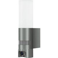
| Product type | Outdoor LED spotlight with infrared motion detector |
| Brand | Steinel |
| Model | LS 300 S |
| Dimensions (H x W x D) | 241 x 213 x 186 mm |
| Weight | Approx 1.2 kg (estimate) |
| Power supply | 220-240 V, 50/60 Hz |
| Power consumption | 29.50 W |
| Luminous flux | 2,704 lm |
| Color temperature | 4,000 K (neutral white) |
| Light source lifespan | 36,000 h (L70B50 at 25°C) |
| Color rendering index (Ra) | 80 |
| Detection angle (detector) | 240° with 180° angular aperture |
| Detector range | Max. 12 m |
| Time delay setting | 10 s to 15 min |
| Trigger threshold setting | 2 to 1,000 lx |
| Protection rating | IP44 |
| Protection class | II (double insulation) |
| Ambient temperature | -10°C to +30°C |
| Main functions | Infrared motion detection, LED panel orientation (±40° horizontal, +110° to -40° vertical), time delay and threshold settings |
| Maintenance and cleaning | Clean dry with a slightly damp cloth without detergent |
| Safety | Do not look directly at the LED when on from less than 20 cm; installation by a professional |
| Spare parts and repairability | Light source not replaceable; in case of failure, replace entire unit |
| General information | Manufacturer warranty 3 years; energy efficiency class F |
Frequently Asked Questions - LS 300 S STEINEL
User questions about LS 300 S STEINEL
0 question about this device. Answer the ones you know or ask your own.
Ask a new question about this device
Download the instructions for your Lamp in PDF format for free! Find your manual LS 300 S - STEINEL and take your electronic device back in hand. On this page are published all the documents necessary for the use of your device. LS 300 S by STEINEL.
USER MANUAL LS 300 S STEINEL
GB. 13 Follow written instructions!
- Under copyright. Reproduction either in whole or in part only with our consent.
- Subject to change in the interest of technical progress.
2. General safety precautions

Failure to observe these operating instructions presents hazards!
These instructions contain important information on the safe use of this product. Particular attention is drawn to potential hazards. Failure to observe this information may lead to death or serious injuries.
- Read instructions carefully.
- Follow safety advice.
-
Keep instructions within easy reach.
-
Working with electrical current may produce hazardous situations. Touching live parts can result in electrical shock, burns or death.
- Work on mains voltage must only be performed by qualified, skilled personnel.
- National wiring regulations and electrical operating conditions must be observed (e.g. D: VDE 0100, A: OVE-ONORM E8001-1, CH: SEV 1000).
- Only use genuine replacement parts.
- The floodlight enclosure heats up when the light is on. Only align the LED panel once it has cooled down.
- Repairs must be made by specialist workshops.
3. LS 300 S / LS 300
Proper use
LS 300 S
-Sensor-switched LED floodlight with infrared motion detector.
-For indoor and outdoor wall mounting
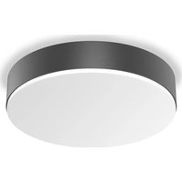
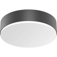
LS 300
-LED floodlight.
-For indoor and outdoor wall mounting
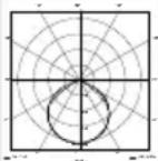
Non-intended use
- The LED floodlight cannot be dimmed.

Not dimmable
Features
-Tilting and turning LED panel.
-Moveable sensor housing (S only) (± 80^)
-Operation via control dial (S only).
-Infrared motion detector (S only).
Operating principle
- Wide-area lighting from efficient LED technology in combination with the opal panel.
LS 300 S only:
- The integrated infrared sensor detects the heat radiated from moving objects (e.g. people, animals).
- The heat detected in this way is converted electronically into a signal that automatically switches ON a connected load (e.g. a light).
- The most reliable way of detecting motion is to install the unit with the sensor aimed across the direction in which a person would walk.
- Reach is restricted when the unit is approached head on.
- Obstacles (e.g. trees, walls etc.) interrupt the line of sensor vision.
- Heat radiation is not detected through obstacles (e.g. walls or panes of glass), the sensor is not triggered.
- Sudden fluctuations in the temperature from changes in weather are not distinguished sources of heat.
Models
LS300S
LS300
Package contents (Fig. 3.1/3.2)
Floodlight adjustment range (Fig. 3.3, 3.4, 6.7)
Sensor unit swivelling range (Fig. 3.3, 6.6)
LS 300 S product dimensions (Fig. 3.5)
LS 300 product dimensions (Fig. 3.6)
LS 300 S product components (Fig. 3.7)
A LED panel
B Enclosure
C Wall mount
D Time setting
E Twilight setting
F Sensor unit
G Ring cover
LS 300 S product components (Fig. 3.8)
A LED panel
B Enclosure
C Wall mount
Technical specifications
Colour temperature: 4,000 K (neutral white)
-Average rated life expectancy:
$$ L 7 0 B 5 0 a t 2 5 ^ {\circ} C: 3 6, 0 0 0 h o u r s $$
-Colour rendering index:
Colour consistency SDCM:
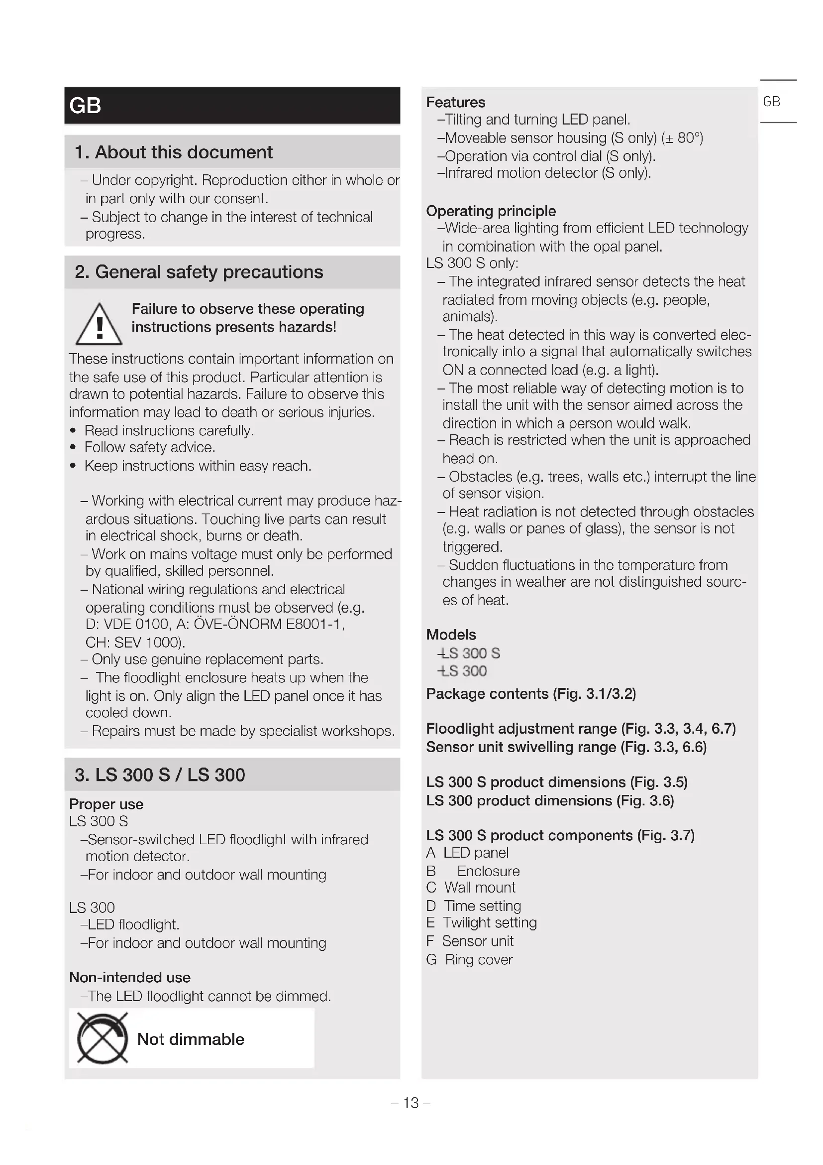
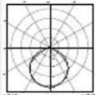
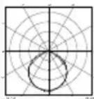
Luminous intensity distribution:
$$ R _ {3} = 8 0 $$
starting value 6
Area illuminated to the front:
$$ 3 5 5 c m ^ {2} $$
- Sensor technology (S onlyS):
passive infrared
-Sensor on standby (P_sh) (S only):
0.50 W
Angle of coverage (S only):
240^ with 180^ angle of aperture
- Sensor unit swivelling range (S only): ± 80°
-Floodlight adjusting range:
$$ t u r n s \text {t h r o u g h} \pm 4 0 ^ {\circ} $$
$$ v e r t i c a l l y + 1 1 0 ^ {\circ} t o - 4 0 ^ {\circ} $$
-Time setting (S only): 10 s - 15 min
- Twilight setting (S only):
2-1,000lux
- Reach (S only):
max. 12 m
- Mounting height (S only):
1.8-2m
- IP rating:
IP44
- Protection class:
4
-
Ambient temperature:
-
10 °C to +30 °C
-
Energy efficiency class:
this product contains
an energy efficiency class "F" light source
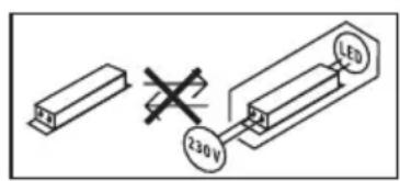
4. Electrical installation
Connection
The supply lead is a 2 or 3-core cable:
L = phase conductor (usually black, brown or grey)
N = neutral conductor (usually blue)
PE = protective-earth conductor (green/yellow)
Note:
The protective-earth conductor need not be connected for this product.
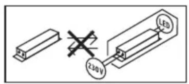
Wiring diagram (Fig. 4.1)
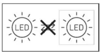
The light source of this LED floodlight cannot be replaced. If the light source needs to be replaced (e.g. at the end of its service life), the complete LED floodlight must be replaced.
5. Installation
Hazard from electrical power.
Touching live parts can result in electrical shock, burns or death.
- Switch OFF power and interrupt power supply.
- Using a voltage tester, check to make sure the light is disconnected from the power supply.
- Make sure power supply remains interrupted.
Risk of damage to property!
Mixing up connection leads may produce a short circuit.
- Identify connection leads.
- Re-connect connection leads.
Preparing for installation
- Check all components for damage. Do not use the product if it is damaged.
-
Select an appropriate site to install the product.
-
Take reach into consideration. (Fig. 5.1)
Take reach and motion detection into consideration. (Fig. 5.2, 5.3)
Vibration-free. - No obstacles in detection zone.
- Not in explosive atmospheres.
- Not on normally flammable surfaces.
- Do not look into the LED light from a short distance (<20 cm).
-
Installing LED floodlight in horizontal position (± 15^)
-
Correctly aiming LED floodlight. (Fig. 5.4)
Mounting procedure
- Check to make sure the power supply is switched OFF. (Fig. 4.1)
- Detach plug-in terminal from wall mount. (Fig. 5.5)
Mark drill holes. (Fig. 5.6) -
Drill holes and fit ground plugs. (Fig. 5.7)
-
Pierce web. Fit sealing plug, feed cable through (concealed power supply lead). (Fig. 5.8)
- Break off one of the two lugs. Pierce web. Feel through cable (surface-mounted power supply lead). (Fig. 5.9)
- Connect conductors. (Fig. 5.10)
- Connect plug-in terminal. (Fig. 5.10)
- Fit enclosure onto wall mount. (Fig. 5.11)
- Screw in locking screw. (Fig. 5.12)
- Switch ON power supply. (Fig. 5.12)
- Make settings "6. Function"
6. Function
Factory settings (S only)
Time setting (E): 10 seconds
Twilight setting (F): 1,000 lux, (daytime mode)
All functions can be set after removing the ring cover.
Time setting (S only) (Fig. 6.1/D)
The time you want the LED floodlight to stay on for (main light) is infinitely adjustable from approx. 10 seconds to a maximum of 15 minutes. Any movement detected before this time elapses will restart the timer.
- Control dial set to + = longest time,approx. 15 minutes
- Control dial set to - = approx. 10 seconds
Twilight setting (S only) (Fig. 6.1/E)
The LED floodlight's chosen response threshold can be infinitely varied from approx. 2 to 1,000 lux.
- Control dial set to = daylight operation (independent of ambient brightness)
- Control dial set to = night-time operation (approx. 2 lux)
The control dial must be turned to when adjusting the detection zone and performing the functional test in daylight.
Note:
When setting the detection zone, it is recommended to
- select the shortest time.
- twilight setting.
Note:
After the LED floodlight switches OFF, it takes approx. 1 second before it is able to start detecting movement again. The LED floodlight will only switch ON in response to movement once this period has elapsed.
Self-test (S only)
When putting the floodlight into operation, the electronic system carries out a self-test which lasts for approx. 1 minute. Once this has been completed, the sensor is active.
Reach setting/adjustment (S only)
The detection zone can be optimised to suit requirements.
Film shroud (S only) (Fig. 6.2)
The film shroud can be used for masking out any number of lens segments to limit reach as required. Inadvertent triggering is ruled out or the sensor can be targeted to watch over danger spots.
(Fig. 6.3, 6.4, 6.5)
- The shrouds can be cut along the grooved vertical and horizontal divisions. (Fig. 6.2).
- Detach ring cover.
- Clip in shrouds at the top of the sensor lens.
- Fitting the ring cover fixes the shrouds firmly in place. (Fig. 6.2)
Sensor unit (S only)
The sensor housing can also be turned through ± 80^ for precision targeting.
- Turning the sensor unit horizontally through
$$ \pm 8 0 ^ {\circ}. \tag {Fig.6.6} $$
Other information:
Floodlight adjustment range (Fig. 6.7)
7. Operation
The LED floodlight is not suitable for burglar alarm systems as it is not tamperproof in the manner prescribed for such systems. Weather conditions may affect the way the LED floodlight works. Strong gusts of wind, snow, rain and hail may cause the light to come ON when it is not wanted because the sensor is unable to distinguish between sudden changes in temperature and sources of heat.
8. Cleaning and Maintenance
Hazard from electrical power.
Contact between water and live parts can result in electrical shock, burns or death.
- Only clean tool in a dry state.
Risk of damage to property!
Using the wrong detergent can damage the light.
- Clean unit with a moist cloth without detergent.
Important note: the control gear cannot be replaced.
9. Troubleshooting
Unit without power.
-
Fuse not switched ON or faulty.
-
Switch ON fuse.
-
Change faulty fuse.
-
Break in wiring.
-
Switch ON mains switch.
- Check wiring with voltage tester.
- Short circuit in mains power supply lead.
- Check connections.
Unit does not switch ON.
-
Wrong twilight setting selected.
-
Re-set brightness response threshold
- Mains switch OFF.
-
Switch ON mains switch.
-
Fuse not switched ON or faulty.
-
Switch ON fuse.
-
Change faulty fuse.
-
Detection zone too small or incorrect.
- Check and adjust detection zone.
Light source faulty.
- The light source cannot be changed. Completely replace unit.
Unit does not switch OFF.
-
Continued movement within the detection zone.
-
Check detection zone.
- If necessary, limit or change detection zone.
Unit switches ON when it should not
- Movement within the detection zone, e.g. from animals, trees or cars.
- Check detection zone.
-
If necessary, limit or change detection zone.
-
Unit is moving as a result of gusts of wind or precipitation.
- Mount unit on a firm surface.
10. Disposal
Electrical and electronic equipment, accessories and packaging must be recycled in an environmentally compatible manner.
not dispose of electrical and electronic equipment as domestic waste.
EU countries only:
Under the current European Directive on Waste Electrical and Electronic Equipment and its implementation in national law, electrical and electronic equipment no longer suitable for use must be collected separately and recycled in an environmentally compatible manner.
11. Declaration of Conformity
STEINEL GmbH hereby declares that the LS 300 S / LS 300 conforms to Directive 2014/53/EU. The full wording of the EU Declaration of Conformity is available for downloading from the following Internet address: www.steinel.de
12. Manufacturer's warranty
Manufacturer's warranty of STEINEL GmbH, Dieselstrasse 80-84, DE-33442 Herzebrock-Clarholz, Germany
All STEINEL products meet the highest quality standards. For this reason, we, the manufacturer, are pleased to provide you, the consumer, with a warranty under the following terms and conditions:
The warranty covers the absence of deficiencies which are proven to be the result of a material defect or fault in manufacturing and which are reported to us immediately after detection and within the warranty period. The warranty shall apply to all STEINEL products sold and used in Germany - excluding STEINEL Professional products.
You can opt for warranty cover in the form of repair or replacement which will be provided free of charge (if applicable, in the form of a successor model of the same or higher quality) or in the form of a credit note.
The warranty period for the STEINEL product you have purchased is 3 years (5 years for products from the XLED home range) in each case from the date on which the product was purchased.
We shall bear the shipping costs but not the transport risks involved in return shipment.
Statutory rights accruing from defects, gratuityousness
The warranty cover described here shall be applicable in addition to the statutory rights of warranty - including special consumer protection provisions - and shall not restrict or replace them. Exercising your statutory rights in the event of defects is gratuitous.
Exemptions from the warranty
All replaceable lamps are expressly excluded from this warranty. In addition to this, the warranty shall not cover:
- any wear resulting from use or any other natural wear of product parts or any deficiencies in the STEINEL product that are attributable to wear caused by use or other natural wear,
- any improper or non-intended use of the product or any failure to observe the operating instructions,
- any unauthorised additions, alterations or other modifications to the product or any deficiencies attributable to the use of accessory,
-supplementary or replacement parts which are not genuine STEINEL parts, - any maintenance or care of products that is not carried out in accordance with the operating instructions,
- any attachment or installation that is not in accordance with STEINEL's installation instructions, - any damage or loss occurring in transit.
Application of German law
The warranty shall be governed by German law excluding the United Nations Convention concerning the International Sale of Goods (CISG).
Making claims
If you wish to make a warranty claim, please send your product complete and carriage paid with the original receipt of purchase, which must show the date of purchase and product designation, either to your retailer or directly to us at STEINEL (UK) Ltd. - 25 Manasty Road, Axis Park, Orton Southgate, GB- Peterborough Cambs PE2 6UP United Kingdom. For this reason, we recommend that you keep your receipt of purchase in a safe place until the warranty period expires.
FR
-Dimensioni (A x L x P):
LS 300 S: 241 × 213 × 186 mm
LS 300: 218 × 213 × 184 mm
-Potenza assorbita (P_op) : 29,50 W
-Flusso luminoso (120^) : 2.704 lm
-Ftargettemperature: 4.000 K (noytralhvit)
-Middels levetid:
$$ L 7 0 B 5 0 v e d 2 5 ^ {\circ} C: 3 6. 0 0 0 t i m e r $$
- Projisert flate front:
355 cm²
- SensorTeknikk (kun S):
passiv-infrarod
-Standby sensor (P_sh) (kun S):
0,50 W
-Svetelny tok (120°): 2.704 lm
-Uhel polovicn' hodnoty: 51^
-Ucinnost: 92 l/m/W
-Svetelny tok (120°): 2.704 lm
-Uholvyzarovania: 51^
-Efektivnost: 92 lm/W
- Sietová prípojka: 220-240 V, 50/60 Hz
-Teplota farby: 4.000 K (neutrélna biela)
-Priemerná dimenzovanaživotnost: L70B50 pri 25 ^ C :36.000 hod.
-Index reprodukcie farieb: R_g = 80
-Konzistencia farieb SDCM:
LED reflektor不同程度 is a great source of information on the properties of different types of LEDs. The LED reflectors are classified into three categories: photovoltaic, solar and photovoltaic with photovoltaic being the most common type.
8. Čiśćenje i njega

- Anduritehnika (ainult S):
passivne infrapuna
-Ootereziim (sensor) (P_sh) (ainult S): 0,50 W
-Tuvastusnurk (ainult S):
$$ 2 4 0 ^ {\circ} \text {a v a t u s n u r g a g a} 1 8 0 ^ {\circ} $$
Hnana3OH Ha n3MeCTBaHe cEH3Op (pnc. 3.3, 6.6)
Pa3mepn Ha npoynkTa LS 300 S (pnc. 3.5)
Pa3mepn Ha npoDyKta LS 300 (pnc. 3.6)
IperneHa ypea LS 300 S (pnc. 3.7)
A LED-naheI
B Kopnyc
C CToiKa 3a CTeHa
D HacTpoiKa Ha BpeMeTo
E Hactpoika Ha CBETIOUyBCTBNTeJIHOCTTa
FCeH3Op
G Kpbrla 6JeHda
IperJeHa ypeLa LS 300 S (pnc. 3.8)
A LED-naHEI
B Kopnyc
C CToiKa 3a CTeHa
TexHnueckn daHHN
- Pa3mepn (B × Lx × D):
$$ L S 3 0 0 S: 2 4 1 \times 2 1 3 \times 1 8 6 M M $$
$$ L S 3 0 0: 2 1 8 \times 2 1 3 \times 1 8 4 M M $$
-KoHcymnpaHa MoUHocT (P_or) : 29,50 W
-CBeTnHHeN nToK (120^)
$$ 2. 7 0 4 \mathrm {I m} $$
- bTbN C NOJIOBnH MOUHOCT:
$$ 5 1 ^ {\circ} $$
- EdekeTMBHOCT:
$$ 9 2 \mathrm {I m} / W $$
- 3axpaHbAHe:
$$ 2 2 0 - 2 4 0 V, 5 0 / 6 0 H z $$
- TemnepaTypa Ha Lbeta:
$$ 4. 0 0 0 K (e c t e c t b e h o 6 8 n o) $$
CpeHa npOdbJnxHTeJIHOCT Ha XnBOT:
$$ L 7 0 B 5 0 p n 2 5 ^ {\circ} C: 3 6. 0 0 0 \text {u c a} $$
- INdeKc Ha CBETOBOT OtpaxKeHne:
$$ R _ {a} = 8 0 $$
-KoHcNCTeHcIyHa cIbTa SDCM:
$$ \text {H a u a n h a C T O I N H O C T 6} $$
Pa3npeneneHne Ha CBETnHaTa:
-06xbaHaTa nIIOu OTnpei;
$$ 3 5 5 c m ^ {2} $$
- Ceh3op (camo S): nacuBEN INHpaepBEN ceh3op
-Standby ceH3op (_sb) (camo S): 0,50 W
- bngnHa 06xBaT (cAmO S):
$$ 2 4 0 ^ {\circ} c 1 8 0 ^ {\circ} \text {b r b n H a p a 3 T B O P} $$
-ДиаэзOH Ha n3MeCTBaHe ceH3Op (cAmO S):
$$ \pm 8 0 ^ {\circ} $$
-ДиаэзOH Ha OTKIOHeHne Ha npoxKeTopa:
$$ x o p u n 3 0 H T a N H O \pm 4 0 ^ {\circ} $$
$$ B e p T N K a l h o + 1 1 0 ^ {\circ} \text {D O} - 4 0 ^ {\circ} $$
-
Hactpoika Ha BpeMeTo (cMo S): 10 c-15 MmH
-
HacTpoIka Ha CBETIOUyBCTBNTeJIHOCTTa
$$ M a K C. 1 2 M $$
- BincounHa Ha MoHTaX (cAmO S):
$$ 1, 8 - 2 M $$
-Bn3aunta:
$$ I P 4 4 $$
- Knap Ha 3aunTa:
/
- Okonha Temnepa/:
$$ - 1 0 ^ {\circ} C, \Omega O + 3 0 ^ {\circ} C $$
- Knap eHeprnuHa epeKTHBHOCT:
To3n npoynkT npntexkaBcBETnHHeH n3TOyHnK
$$ C K N A C H e H e p r i n h a e f e k T u B H O C T, F ^ {a} $$
4. EneKtpnuecka nHcTaJaCna
Cbbp3BaHe
Ka6eJIbT cIbIbPka 2 nII 3 npOBoNDnka:
L = φa3a (O6NKHOBeHo YepeH, KaFyB UJIN CNB)
YpeBbT He Ce BKJIIOUBa.
- HacTroPkata Ha CBETNoCyBCTBnTeHOCTTa e nOrpeuHo HanpaBeHa.
3aeneCTBaUataOcBeTeHocTda ce HacTpon HaHOBO. - PpeKbCBAuybTe n3KJIIOueH.
-
Прекьсавт Да се Вклочи.
-
DepeKTeH nIIN 3KNIOUeH npEpa3nTeJ.
-
Празителгд acce BKHIOUH.
-
DepeKTHIgT npedna3nteJa ca ce 3aMeHn.
-
O6xbaTbTe TBbpDe MaNbK NnN HeToeH.
- 06xbaTbT da ce npOBepn n HacTpon.
- DepeKTHO OCBETHTHO TJIIO.
OCBETIHTO TAYHO He e 3aMeHReMO. LJIyT ypeJ da ce 3aMeHN.
YepeT He ce n3KJIOUBa.
-
PpOdbJxKaBaUo DnBxKeHne B OxbaTa.
-
06xbaTbT da ce npOBepn.
- Пи НeoБхОДМоСТ OБXBaTBТ Да Се ORpaHn-у ИЛИ N3MeHn.
YpeBbT Ce BKNIOUba npOn3BOJHO.
A CBeToIIOIHaI nHaHeIb
B Kopriyc
C KpoHwTeHH
TexHueckne daHHbIe
$$ L S 3 0 0 S: 2 4 1 \times 2 1 3 \times 1 8 6 M M $$
$$ L S 3 0 0: 2 1 8 \times 2 1 3 \times 1 8 4 M M $$
- Pa3Mepb1 (B × LII × Γ):
- NopTepeJnemar MOUHOCtB (P_on) : 29,50BT
-CBETOBONOTOK(120°): 2.704JIM - YrOJ NIOJOBUNHHOR 3HaueHn: 51^
- ΘΦΦeKTINBHOCTb: 92 JIM/BT
- CeteBoe nOdknHouHeHne: 220-240B,50/60T
Tempepatypa LBeTa:
$$ 4. 0 0 0 K (\text {H e n T p a l b h i} \text {B i n b e n b i}) $$
- CpeHn paCteHbI cpoK cnyk6bl:
$$ L 7 0 B 5 0 p n 2 5 ^ {\circ} C: 3 6. 0 0 0 \mathrm {u} $$
-Ko3ΦΦnIeHT CBTeOpEpaH:
-KoHcNCTeHcIy cBcTa SDCM:
$$ \text {H a y a n b H o e 3 h a y e H i n e} 6 $$
- PacnpedeeneHne cInbI CBeta:
-Прoeцированная NOВерхноctь Впереди: 355 cm²
- Cechopna Texnka (ToJIbKO S): naCCnBHyI NK
- Standby ceHcopa (P_sh) (TolbKO S): 0,50 B
- YrOJ o6HApUxKeHnra (ToJIbKO S): 240° c yrIOM pactBopa 180°
-Диаэзн Двixжени ceHcopHoTo 6LoKa (ToIbko S): ±80°
-Диаэн NOBOPTa npoxKeTopa: no ropu3oHTaJIu ± 40^ or 110^ do -40° no BepTuKaJIu
- Peruginopobka BpeMeHn (ToIbKO S): 10 ceK. -15 mH.
- YctaHOBka cyMepeuHoro BKJIIOUeHnra (TolbKO S): 2 -1.000 JK
- PaIInyc DeIeCTBnA (TOJIbKO S): MaKc. 12 M
-MoHTaXHaBbICota(TOJIbKO S): 1,8-2M
- BnD 3aunTbI: IP 44
- Klaacc 3aunTbI:
- Tempepa typa okpykaioe cpebl: oT-10 ^ C 1o +30 ^ C
- Klaacc 3HeprooΦΦeKTHBHOCTN: DaHHOe N3dJIne COePKeNT IVcToYHK CBeta Klaacca 3HeprooΦΦeKTHBHOCTN, F".
4. 3JIeKTpOMOHTaX
PoiKJIIOUeHne
Cetebo npobod coctou 3 2 nn 3 xnl:
L =фаза (обьчно черно, Корунчевого впсерогоцета)
N =HyJIeBOI npOBOi (HaIe BcERo CINHnI)
PE = npoBOJ 3a3eMJIeHnra (3eJIeHbI/JKeJIbI)
Yka3aHHe:
PpOBoD 3a3eMJIeHnI IJIa 3TOrO n3JeJIInIg NODKJIIOuHaTb He Tpe6yETc.
Dnarpamma nodkJIOueHn (pnc. 4.1)
IcToHnK CBeta 3TOrO CBeToNDHO rpoXekTopa He noJnxknt 3aMeHe. Pn Heo6xOIMocTn 3aMeHb IcToHnKa CBeta (HaPmEep, B KOHc eero cPoKa CJyX6bl), Heo6xOIMo 3aMeHHTb BeCb CBeToNDhBn IpOxKeKTop.
5. MoHTax
OnacHocTb n3-3a ydapa 3JneKtpnueckm TOKOM!
Прикочовене К TOKОпpoвоялм Деталм MOжET РИВODиь K удару ЗлЕКтчecKM TOKOM, OЖКOram ИЛДЯТаьHOMY ICXODY.
- OTKIIOHTb 3JIeKTpIYeCTBO I npepBaTb IOnaHy HAnpJxKeHn.
- Поберпь OTCYCTBNE Наразжени ИндИКATOpOM наразжени.
- ObecneuTb, yTo HapjKeHne He nOdaetc.
Onachoctb MMyueCTBeHHoro yuepe6a!
3aMeHa CoeINHITeNBbIX KaBcIeN MOKeT pInBOdHTb K KOpOTKOMy 3aMbIKaHIO.
- IndHTnIphuIupoBaTb COeINHITeNbHbIe Ka6eJI.
3aHOBO NOcOeINHHTb CoeINHITeBHBie Ka6eJI.
IoproTOBkaMOHTaKa
- Поберпь BCE KOHCTpykTINBHBIe DeTaIIHa
- петмет NOBpejKdEHHa. Пи NOBpejKdEHHaX He
- BKNIOUaTb npOdyKT.
- Bb6paTb noDxOJaee MeCTo Dnra MOHTaxa.
-CyueTOMpaunycaJeNCTBnA.(pnc.5.1)
C yHeTOM peRnCTpaUIN DvNKeHn. (pnc. 5.2, 5.3)
-
Be3 Bn6paui.
-
3oHa oxBaTa CBo6OJa HT npEeTCTBn.
- He BO B3pyBIOONaCHbIX 30Hax.
-
He ha nerko BO3ropaembIX NOBepxHOCTX.
He cmOTpeTb Ha CBETOIOHbI CBETINbHnK C He6OJIbWOro paCCToHnR (<20 cm).
MoHTaK CBeToDnOdHOro npOKeKTopa B rOpN3OHTaIbHOM NOJIOKeHm (±15°). -
CBETOIOIHOHII npOXeKTop BblpOBHrTb KoppeKTHO. (pnc. 5.4)
Popraok MoTaKa
-Поберпь,OTКючehалnoячаннржен. (pnc.4.1)
- OTcoeINHITb KOHTaKTThbI 3aXkIM OT KPOHlTeiHa. (pnc. 5.5)
- Hametntb OTBepCTnIa CBepHeH. (pnc. 5.6)
-ПосверлNTь OTВерстя И BCTaBHTь Дюбел. (pnc.5.7)
- Побит bперонк. BCTaBt b yNIOTHIteIb
n npOTaHyTb Ka6eIb (noDBoD Ka6eJЯ cKpbIToI
npOBoIDkoI). (pnc. 5.8)
- CoŋhyTb OndHy n3 DByx HaKlaIaOK. ПрбИтьперенКу. ПрOTЯнТь KaБел (ПОДВOD КаБЕЯ OTКpbIToI npOBoDkoI). (pnc. 5.9)
-ПОДКЛЮЧТБ COEДИНТЕЛБНБИ KABeJIb. (pnc.5.10)
- CoeHHHTb KOHTaKTHbI 3aKIM. (pnc. 5.10)
HaTeB KOpNyc Ha KpOHN. (Pnc. 5.11)
Bkpyntb kpeenekhbl BnHT. (pnc. 5.12)
BknIOuHTb 3eKtponTaHne. (pnc.5.12)
- BbinoHnHt bpeylnpObKn → "6. 3KcnnyaTaun"
6. 3Kcnpnyatauia
3aBODCKHe HacTpoIKN (ToJIbKO S)
ПюДОЛЖИТЕЛБНOCТВ BKЛIOUЧЕнЯ (E): 10 ceKунд Установka симерчно ВКЛIOUЧЕня (F): 1.000 Лк, (Дnevвий рек imm)
Bce cyHKcIMMOKHO yCTaHObNTb npi cHrToI neKOpatNBHO 6JeHne.
PerynpoBka BpemeHn (ToIbKO S) (pnc. 6.1/D) Heo6xoJIMoe Bpemr OCBeUeHn CBeTOIOHO r npoxekTopa MoKet 6bItb yCTaHOBLeHO pIaBHO B dnaIa3OHe ot npim. 10 cek. do MaKc. 15 MIn. KaXdoe 3apeNtprpOBaHHoe DmIXKeHne Do nCTeHnE 3TOrO BpemeHn 3aHOBO HaunHaET OTCHT BpemeHn.
- YctaHOBOHbI peYJrTOp Ha + = OK. 15 MInH.
- YctaHOBOUHbI peYJrTOp - = OK. 10 cek.
YcTaHOBka cyMepeHOro BKJIIOueHnra (ToIbKO S) (pnc. 6.1/E)
XeIaEmbI npor cpa6aTbIBaHnC BcTeOIOHOrnpoxKeTopa MOxHO yCTaHOBHTb PnaBHO OT pIM.2do1.000nk.
- PernylaryTop, yctaHOBJIeHHbI Ha = pexIM DHeBHOro OCBeUeHnra (He3aBNCIMO OT JRPKOCTN)
- YctaHOBOUHbI peYJrTOp, yCTaHOBJIeHHbI Ha = pexIM cyMepeuHOrO ocBeJeHnR (OK. 2 JIK)
Ipn yctaHOBKe 30HbI o6hApxKeHn I npnpoBeHnN EKcNlyatauONHO Tecta npn DHeBHOM CBTe YCTaHOBOHyBn peYJrTOp dOnJKeH 6bITb yCTaHOBNeH Ha
Yka3aHHe:
PekomeHdaunIaHaCTpOuKN 30HbI o6HapyKeHHNIA:
- Bыбираьcamoe KopoTkoe Врем.
- BbINOJIHHTb HAcTpOuKy dIy CympeK.
Yka3aHHe:
Iocne KaKDoRo npOcecca OTKIOUHeHn CBTeOnIOndHO npOKeKTopa 6hApUxKeHnHOBOrDINHENppepbBaetc npIM. Ha 1 cekHy. ToJIbKO nIOCTeHn3TOrO BpeMeHN CeHCOPHbI pOKeKTOpMOKET CHOBA BKIOuHaTcCBETnpN DInXKeHn.
CamokOHpoJIb (ToJIbKO S)
Пи ВБОд eВ 3КСЛУаТAUH OJeKТрОнka BыПОЛ-нгсamOKOHТрОь b TteЕнe Ппm. 1 MИHyтbl. 3aTeM ceHCOP aKTINBeH.
YcTaHOBKa paAnuCa DeIcTBn /peRyIInpOBKa (ToJIbKO S)
Pn Heo6xOIMOCTN MoKHO PPOU3BecTu ONTINMaIbHyIO HAcTpoKy 30HbI OShApYKeHnI.
3aKpbBaIOUca nIeHka (ToIbKO S) (pnc. 6.2)
Iolucpeepueeckra 3acnoHka npedHa3Haayetcra 3acnoHa ceMeHTOB IIN3bl, T.e. IyMeHb-WeHnpaDnyCa DeNCTBnB KAKDOM OTJeNbHOM Cnyae.IckNoaHTcOOn6oOHyIe nepeKlOyeHn IIn OcyuectBnEETcIeHaNPaBJIeHHb KOH-TPoJb 3a OnaChbIM MeCTAm.(pnc.6.3,6.4,6.5)
-Пolyccpeepueeckne 3acnoHK moxho OTopBaTb BdoJIb BEpTNkaJIbHbIX n rOpN3OHTaJIbHbIX nep-ΦopauNoHHbIX JINHn. (pnc.6.2).
- YdaIITb DeKopaTnBHyIO 6JIeHny.
3acJIOHKn KpeTcB BepxHeN 3OHe ceHCOPHOJINH3bl.
- IocJIe yCTaHOBKn DeKOpaTINBHOJ 6JIeHbI
- IOnycfepnueckne 3acJIOHKn pOuHNo fNkCnpyIOTcR. (pnc. 6.2)
CehcOpHbI 6Jok (ToIbKO S)
IyTem NOBOPTa ceHcOpHOro Kopnyca Ha ± 80° MOXKHO TaKKe Ipon3BOIDtB TOHyIO HAcTPOkY.
-ПоворOT ceHcOpHOrO 6Ioka NO rOpN3oHTaII Na ± 80^ .(pnc.6.6)
PpOuee:
3oHa noBopoTa rOIOBkn npoxKeToppa (pnc.6.7)
7. 3Kcnpnyataua
CBeToIOIbI pOKeKTop He npEHa3HaueH dJI npIMeHnB KauEcTBe OXpaHHo CnIHaII3aUIN, T.K. He IMeET Tpe6yEmo rapaHTn NCKIoUeHn ca60taxa. IoroNbIe ycIOBn MOrT BInrTa H pa60Ty CBeToIOHOr npOKeKTopa. Ppi CNlb-HbIX IopbIBax Betpa, MeTeJI, DoXke, rpaDe MoKet Ipon3OITN OwNIbOCHoe BKIOUcHHe, NOCKOJIbKy ceHCOp He cNoCo6eH OTIIuHaTb pe3KOE n3MeHHeNe TEMpePaTypbl Prn pe3KOM n3MeHnN IroOHBIX ycIOBn OT DmIXKeHn INCTOHNka TeIIOBOrO n3JNy-HeHn DmIKyUxxCs OBekTOB.
8.Чистка и ухов
Onachoctb n3-3a ydapa 3JektpnuecknM TOKOM!
IonoaHne BObI Ha TOKOpOBoJaUne JeTaJIIMoKET npVBODITb K ydApy 3JeKTPnueCKIM TOKOM, OXKOram IJIIN JeTaIbHOMY NCxOy.
-ЧИСТINь Рибор Тольков Сухом COCTОПИ.
Onachoctb mMyueeCTBeHHoro yuepe6a!
HenpaBnIbHbIe YIcTgUne CpeDCTBa MOryT NOBpeDITb N3dJIeNt.
- YnCTnTb npi6op cIeRka yBlaXHeHHO TpIKNo 6e3 YnCTraux CpeICTB.
Baxho:Pa6oyee n3dJIne 3aMeHHTb HeJIb3J.
9. YcTpaHHeNc6oEB
Pn6op 6e3 Hapjxehn.
- PpeoXpaHnteIb He BkIIOueH IIN HeINcnpaBeH.
BknHouHTb npedoxpaHnteJIb.
3aMeHnTB HeNCnpaBHyI npedoxpaHnteJIb.
-06pbkka6jra.
BknIOuHTb cTeBOB BbIKIOUaTeJIb.
- Поберпь повд ИнданkaTopOM Hanржени.
-KopoTkoe 3aMbIkaHne Ha CeTeBOM IpOBoJe.
- PpOBepntb coeINHeHnA.
I3dJIne He BKJIOUaETc.
- HenpaBnIbHO Bbl6pHa yCTaHOBka CymepeHOro BKJIIOUHeHr.
-
RpkocTb cpa6aTbIBaHn yCTaHOBtB 3aHOBO.
-
BbIKIOUeH cTeBOB bIKIOuOaTeJIb.
BknIOuHTb ceTeBOB BbIKIOUaTeJIb.
- PpeoXpaHnteIb He BkIIOueH IIN HeNCpABeH.
BkHIOuHTb npEOxpaHnteJIb.
3aMeHnTb HeNCpabHbI npedoxpaHnteJIb.
-
3oHa OxbaTa CnIuKOM MaIeHbKaI IIN He KoppeKTHaI.
-
Поверпь зону обарухени и отperlуни ровать.
-
IVCTOCHNK CBETA HENCnpaBeH.
- NCTOCHN K CBeta He NOJIeKHT 3aMeHe. 3aMeHHTb IN3JeJIne NOJHOCTbIO.
I3dJIeHHe BbIKIOHaeTcra.
-
NocToHHoe DnHexeHne B3OHe ObHaPyXeHnIa
-
Поверпь зону обаруженя.
-Пи Heo6xOДIMOCn OрpaHnHTb 3OHy OxBa-Ta NIN N3MeHNTb.
HexeIaTeJIbHoe BkJIIOUeHne np6opa.
ДИЖЕНБЗОЕОБHApYKeHЯ,HaPIMeP, KINBOTHbIe,DEpeBbI NIM MaunHbI.
- Поверпь зону обаруженя.
- Pn Heo6xOJIMOCtN OrpaHnHTb 3OHy OxBa-Ta NIN N3MeHNTb.
He BbIbpaCbIBaTb 3neKTpponpnbOpbl B 6bITOBBIE OTXObI!
TolbkoДлгСтран EC:
Corgnacno DeNCTByUOSeE EbponeeCKoI DnpeKtNBe NO Otpa60TaHHOMy 3JeKtpuHeCKOMy I 3JNeK-
TPOHOMy 6OBpyoBaHIO H ee peaJIN3aCIMN B HaOnHOJIbHbIX 3aKoHOJaTeJIbCTBax OTpa6OtaHHIe 3JIeKTPoPn6OpbI DOJXHbI CO6HpTaBcR OTdJIbHO IHaPabJIbTbcr Ha 3KoJIoRnHyIO BTOpUHyIO nepepa6OTky.
11. CeptnuΦnKAT COOTBETCTBnA
Hactoam KOMnna Hs STEINEL Gmb 3aBnert,
TO paAnopapatypa Tnpa LS 300 S/LS 300
OTBeaet TpeBoAHm DnpeKtNBb2 2014/53/EU.
Iohn b TeKCT cepTnФkata COOTBeTCTBnE C
DOctynn nCleNyOuemy aDpEscy B INTePhe:
www.steinel.de.
12.Гарази npoN3BODnteJI
Гараня поньдпелЯ STEINEL GmbH,
Dieselstraße 80-84, DE-33442 Herzebrock-Clarholz,
Германя
DahHoe n3dJIe npOn3BODCTBa Steinel 6bIIO C OcO6bIM BHNMaHnEM N3rOTOBJeHO N NCbITaHO Ha pa6oTOcNOcO6HoCTb N 6e3OnaCHOCTb 3KcNpyaT aUm COOTBETCTBEHNO DeiCTByOUIm VHCTpyKUma, a NOTOM NOBeprHyTo Bbl6OpOHMy KOHTPOJIO KaHeCTBa.
ΦnnpMa STEINEL rapaHTnpyeT BbICOKoe KaeeCTBO nHaedekHyIO pa6Ory N3dEJIy. TaepaHTnHbI cPOK 3KcNpyaTAtuIN COCTABJRE T 36 MeCraeB CO DnI npOdaXn N3dEJIy. ΦnPMA o63yETcYCTpaHNTb HeoctATKn, KOTOpBIE BO3NHKJI IN BCJeDCTBne DepekTa MaTePnaJa IIN KOHCTpyKUIn. DepeK-TbI yCTpaHЯOTcnyTEM peMOHTa N3dEJIy JIN60 3aMeHO HEnCpabHBIX DeTaleN IO YCMOTpeHHIO fPnMbI. TaPaHTnHbI cPOK 3KcNpyaTAtuIN He pacnPoCTpaHЯETcN Ha NOBpeXJDeHnN I DepeK-TbI, Bo3NHKUIne B pe3yJbTaTe N3HOca DeTaleN, HeaNDexKaUSeN 3KcNpyaTAtuIN uXOda. FnpMa H HeCet OTBETCTBeHHOCtN 3a MaTePnaJIbHbI yUepe6 TpeTBx JInC, HAnecEHbI B IpOueCE 3KcNpyaTAtuIN N3dEJIy. TaPaHTnI ppeOCTaBLReTcN TOlbKO B TOM CInyae, EcIn N3dEJIne B CO6paHHom N yNa-KOBaHHOM BVde C KpATKIM OINCAHNEM HeNCnPabHOCTNs bblO OTnpaBNeHO BMeCTe C npINoXKeHHbIM KACCOBbIM YeKOM NIN KBNTaHUne (C DaToN npOdaXn N NeaTbIO TOPROBOr PpeDnPrTn) NO aDpecy cepBnCHOn MaCTepCKoN.
PemOHThbIcBVC:No nCTeueHn rapaHTnHO- ro cPoKa IJIN pRn HAIuHn HeNOLaOK, NCKIO- yauUxr rapaHTIO, o6paTntEcB 6bnkaiWee
cebpncoe npdpnpnTne,TO6bI pOlyuHTb INHOpMaUIO BO3MOKHOCTN peMOHTa.


- General safety precautions
- Failure to observe these operating instructions presents hazards!
- LS 300 S / LS 300
- Proper use
- Non-intended use
- Not dimmable
- Features
- Operating principle
- Models
- LS 300 S product components (Fig. 3.7)
- LS 300 S product components (Fig. 3.8)
- Technical specifications
- Electrical installation
- Connection
- Note:
- Wiring diagram (Fig. 4.1)
- Installation
- Hazard from electrical power.
- Risk of damage to property!
- Preparing for installation
- Mounting procedure
- Function
- Factory settings (S only)
- Time setting (S only) (Fig. 6.1/D)
- Twilight setting (S only) (Fig. 6.1/E)
- Self-test (S only)
- Reach setting/adjustment (S only)
- Film shroud (S only) (Fig. 6.2)
- (Fig. 6.3, 6.4, 6.5)
- Sensor unit (S only)
- Other information:
- Operation
- Cleaning and Maintenance
- Troubleshooting
- Unit without power.
- Unit does not switch ON.
- Unit does not switch OFF.
- Unit switches ON when it should not
- Disposal
- EU countries only:
- Declaration of Conformity
- Manufacturer's warranty
- Statutory rights accruing from defects, gratuityousness
- Exemptions from the warranty
- Application of German law
- Making claims
- FR
- Čiśćenje i njega
- Pa3mepn Ha npoynkTa LS 300 S (pnc. 3.5)
- Pa3mepn Ha npoDyKta LS 300 (pnc. 3.6)
- IperneHa ypea LS 300 S (pnc. 3.7)
- IperJeHa ypeLa LS 300 S (pnc. 3.8)
- TexHnueckn daHHN
- EneKtpnuecka nHcTaJaCna
- Cbbp3BaHe
- YpeBbT He Ce BKJIIOUBa.
- YepeT He ce n3KJIOUBa.
- YpeBbT Ce BKNIOUba npOn3BOJHO.
- TexHueckne daHHbIe
- 3JIeKTpOMOHTaX
- PoiKJIIOUeHne
- Yka3aHHe:
- Dnarpamma nodkJIOueHn (pnc. 4.1)
- MoHTax
- OnacHocTb n3-3a ydapa 3JneKtpnueckm TOKOM!
- Onachoctb MMyueCTBeHHoro yuepe6a!
- IoproTOBkaMOHTaKa
- Popraok MoTaKa
- 3Kcnpnyatauia
- 3aBODCKHe HacTpoIKN (ToJIbKO S)
- YcTaHOBka cyMepeHOro BKJIIOueHnra (ToIbKO S) (pnc. 6.1/E)
- CamokOHpoJIb (ToJIbKO S)
- YcTaHOBKa paAnuCa DeIcTBn /peRyIInpOBKa (ToJIbKO S)
- 3aKpbBaIOUca nIeHka (ToIbKO S) (pnc. 6.2)
- CehcOpHbI 6Jok (ToIbKO S)
- PpOuee:
- 3Kcnpnyataua
- 8.Чистка и ухов
- Onachoctb n3-3a ydapa 3JektpnuecknM TOKOM!
- Onachoctb mMyueeCTBeHHoro yuepe6a!
- YcTpaHHeNc6oEB
- Pn6op 6e3 Hapjxehn.
- I3dJIne He BKJIOUaETc.
- I3dJIeHHe BbIKIOHaeTcra.
- HexeIaTeJIbHoe BkJIIOUeHne np6opa.
- TolbkoДлгСтран EC:
- CeptnuΦnKAT COOTBETCTBnA
- 12.Гарази npoN3BODnteJI
Brand : STEINEL
Model : LS 300 S
Category : Lamp