IS 2160 ECO - Motion detector STEINEL - Free user manual and instructions
Find the device manual for free IS 2160 ECO STEINEL in PDF.

| Product type | Infrared motion detector |
| Brand | Steinel |
| Model | IS 2160 ECO |
| Dimensions (H × W × D) | 113 × 78 × 73 mm |
| Power supply | 220-240 V, 50/60 Hz |
| Detection angle | 160° |
| Maximum range | 12 m |
| Maximum detection area | Approx. 165 m² |
| Horizontal adjustability | 40° (with orientation device) |
| Vertical adjustability | 70° |
| Twilight setting (response threshold) | 2 to 1,000 lux, continuously adjustable |
| Time delay (timer) | 5 seconds to 35 minutes, continuously adjustable |
| Maximum connected lighting power (incandescent/halogen lamp) | 600 W |
| Maximum connected lighting power (LED/electronic ballast) | 250 W (max. 50 devices, C < 88 µF) |
| Protection | 10 A line circuit breaker recommended |
| Protection rating (IP) | IP54 |
| Operating temperature | -20 °C to +50 °C |
| Recommended mounting height | Approx. 2 m |
| Maintenance and cleaning | Clean the lens with a damp cloth (no detergent) |
| Manufacturer warranty | 5 years for detectors (subject to conditions) |
| Disposal | Environmentally friendly recycling in accordance with local regulations |
Frequently Asked Questions - IS 2160 ECO STEINEL
User questions about IS 2160 ECO STEINEL
0 question about this device. Answer the ones you know or ask your own.
Ask a new question about this device
Download the instructions for your Motion detector in PDF format for free! Find your manual IS 2160 ECO - STEINEL and take your electronic device back in hand. On this page are published all the documents necessary for the use of your device. IS 2160 ECO by STEINEL.
USER MANUAL IS 2160 ECO STEINEL
Congratulations on purchasing this STEINEL Infrared Sensor and thank you for the confidence you have shown in us. You have chosen a high-quality product that has been manufactured, tested and packed with the greatest care.
Please familiarise yourself with these instructions before attempting to install the sensor since prolonged reliable and trouble-free operation will only be ensured if it is installed properly.
We hope your new Infrared Sensor will give you lasting satisfaction.
Principle
(s. fig. page 2)
The integrated pyroelectric infrared detector senses the invisible heat radiated from moving objects (people, animals, etc.). The heat detected is electronically converted into a signal that switches on loads (e.g. a light) connected to it. Heat is not detected through obstacles, such as walls or panes of glass. Heat radiation of this type will, therefore, not trigger the sensor.
With a detection angle of 160^ and a max. reach of 12 m the sensor watches over an area of approx. 165m^2 .If you only wish to cover a smaller area,reach may be reduced by tilting the sensor unit. Using the swivel mount supplied, the sensor unit can also be turned horizontally, making it possible to target the detection zone exactly as you choose.
The detection angle can also be adjusted to suit individual requirements by fitting shrouds.
Important: the safest motion detection is obtained when the device is mounted and aligned laterally to the walking direction and no obstacles (such as trees and walls, for example) obstruct the view.

Safety warnings
- Disconnect the power before attempting any work on the motion detector.
-
The electrical connection lead must be dead during installation. Therefore, switch off the power first and use a voltage tester to check that the power supply is disconnected.
-
Installation of the sensor involves work on the mains power supply. This work must therefore be carried out professionally in accordance with the applicable wiring regulations and electrical operating conditions. (DE - VDE 0100, AT - ÖVE-EN 1, CH - SEV 1000).
-
Please note that the sensor must be protected by a 10 A circuit breaker. The mains supply lead must be no greater than 10mm in diameter.
The site of installation should be at least 50~cm from a light because heat radiated from it may trigger the sensor unintentionally. To obtain the specified reach of 12m , the sensor should be installed at a height of approx. 2m . Please observe the safety warnings on page 12.
Installation procedure:
- Undo screws on housing 1
- Do not detach wiring from terminal block, but gently pull entire terminal assembly, including sensor unit 2 (cylindrical section), to remove it. The sealing plugs are designed for a mains supply cable with an outer diameter of 5 - 9mm .
- Hold mounting plate 3 against wall / ceiling, mark drill holes, paying attention to wiring runs concealed in wall / ceiling. Drill holes, insert wall plugs (6 mm).
- Break open pre-punched cable entry holes as appropriate for concealed 4 or surface-mounted 5 installation, insert grommets, pierce and pass cable through.
Note: For surface-mounted wiring, it is recommended to install the swivel mount 6 (see below). Alternatively, the unit may be pierced at the thinner section to pass the cable through.
5. Screw mounting plate 3 to wall.
6a) Connecting the mains lead
The mains lead consists of a 2-3 phase cable L = phase conductor N = neutral conductor PE = protective-earth conductor
If you are in any doubt, you must identify the cables using a voltage tester; then disconnect the power supply again. The phase (L) and neutral conductor (N) are connected according to terminal assignment. The protective-earth conductor is connected to the earth terminal A mains switch for ON' and OFF' switching can of course be installed in the mains lead.
6b) Connecting the load supply lead
The load supply lead (e.g. light) is also a 2 to 3-core cable which is connected to terminals N and L'. The live conductor must be connected to the terminal marked L'. Connect the neutral conductor to the terminal marked N together with the neutral conductor of the mains power supply lead. The protectiveearth conductor is connected to the earth terminal
7. Once wiring is completed, insert terminal block together with sensor unit 2 into mounting plate 3, fit housing cover 1 and secure in place with fastening screws.
Installation with swivel mount
The swivel mount 6 allows you to turn the motion detector horizontally. This provides additional adjustment for the detection zone.
- Press cupped pieces 7 out of swivel mount 6 provided with sensor unit.
-
Hold swivel mount 6 against wall and mark drill holes, drill the holes, insert wall plugs, pass cable through. Connect as described in ,Installation".
-
Pass screws through cupped pieces 7 and secure swivel mount 6 in such a way that the screw head is positioned on the smooth side and the domed side rests against the mounting plate 3 (see diagram).
Functions
The system can be put into operation once the sensor has been connected and
installed. Two setting controls are provided on the bottom of the unit.
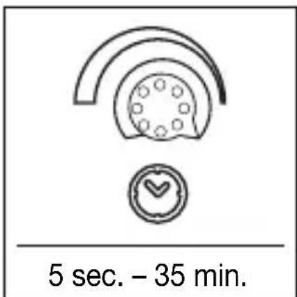
Switch-off delay (time setting)
The chosen light 'ON' time can be varied continuously from approx. 5 sec. to a maximum of 35min The shortest period, approx. 5 sec., is selected by turning the control fully clockwise.
The longest period, approx. 35 mins, is selected by turning the control fully anticlockwise. It is recommended to select the shortest time for adjusting the detection zone and for performing the walk test. Any movement in the detection zone will reactivate the time setting.
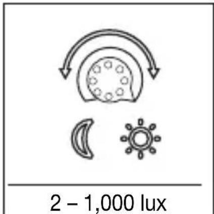
Twilight setting (response threshold)
The chosen detector response threshold can be adjusted continuously from approx. 2 lux to 1,000 lux. Turning the control fully clockwise will select daytime operation at approx. 1,000 lux.
Turned fully anti-clock-wise, the control is set to dusk-to-dawn operation at approx. 2 lux. When adjusting the detection zone and for the performance test in daylight, the adjusting screw must be turned fully clockwise.
Reach adjustment
(s. fig. page 4)
Reach can be reduced by tilting (70^) the sensor. The sensor can be turned horizontally through 40^
(only with swivel mount) to align the detection zone in exactly the way you require.
Precision adjustment using shrouds
(s. fig. page 4)
The adhesive shrouds provided may be used to adjust the sensor's detection
angle to suit individual requirements. This makes it possible, for example,
to blank out neighbouring premises from detection or specifically target paths.
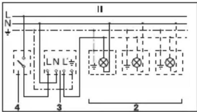
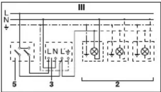
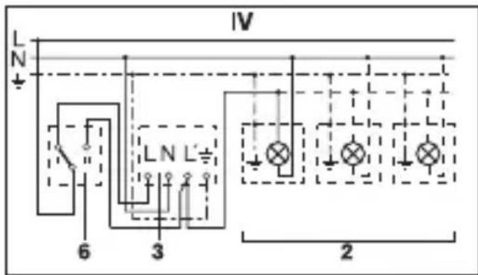
Wiring examples
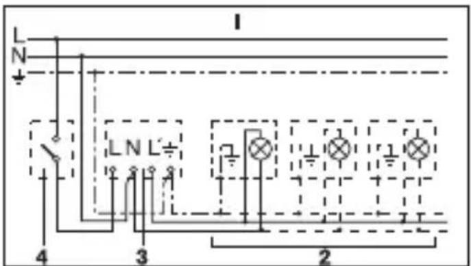
1. Light without neutral conductor
3. Connection using series switch for manual and automatic operation
4. Connection to double-throw switch for permanent light 'ON' and automatic operation
Setting I: automatic operation
Setting II: manual operation for permanent light 'ON'
Important: the unit cannot be switched off, but operated only at settings I and II.
1) e.g. 1 - 4 × 100 W filament bulbs
2) Service load, light of 600 W max. (see Technical specifications)
3) IS 2160 connection terminals
4) Indoor switch
5) Indoor series switch, manual, automatic
6) Indoor double-throw switch, automatic, permanent light 'ON'
Operation / Maintenance
The Infrared Sensor is suitable for switching light ON and OFF' automatically. The unit is not suitable for special burglary alarm systems since it lacks the tampering protection prescribed for this purpose.
Weather conditions may affect the way the motion detector works. Strong gusts of wind, snow, rain or hail may cause the light to come 'on' when it is not wanted because the sensor is unable to distinguish sudden changes
of temperature from sources of heat. The detector lens may be cleaned with a damp cloth if it gets dirty (do not use cleaning agents).
Technical specifications
| Dimensions: (H × W × D) 113 × 78 × 73 mm |
| Output: Incandescent / halogen lamp load: 600 W LED / ECG load: 250 W (50 pcs. c < 88 μF) |
| Connection: 220 – 240 V, 50/60 Hz |
| Angle of coverage: 160° with sneak-by guard |
| Pivoting range: 40° horizontal, 70° vertical |
| Reach: 12 m max. |
| Light threshold: 2 – 1,000 lux |
| Time setting: 5 sec. – 35 min. (factory setting: 5 sec.) |
| Light threshold: 2 – 1,000 lux (factory setting: 1,000 lux) |
| Enclosure: IP54 |
| Temperature range: -20 °C to +50 °C |
Troubleshooting
| Malfunction | Cause | Remedy |
| Without power | • Fuse blown, not switched ‘ON’ •Short circuit | •Renew fuse, switch ‘ON’ mains power switch, check wiring with voltage tester •Check connections |
| Does not switch ‘ON’ | •Twilight setting in nighttime mode during daytime operation •Bulb blown •Mains switch ‘OFF’ •Fuse blown •Detection zone not properly targeted | •Readjust •Replace bulb •Switch ‘ON’ •Renew fuse, check connection if necessary •Re-adjust |
| CauseMalfunction | Remedy | |
| Does not switch 'OFF' | ·Continued movement in detection zone ·Light is in detection zone and keeps switching on as a result of temperature change ·Position Wi-Fi device very close to the sensor ·Set to continuous operation by indoor series switch | ·Check detection zone and re-adjust if necessary or fit shrouds ·Readjust zone ·Increase distance between Wi-Fi device and sensor ·Set series switch to automatic mode |
| Keeps switching 'ON' / 'OFF' | ·Light is in detection zone ·Animals moving in detection zone | ·Change zone, increase distance, reduce output ·Tilt sensor higher or apply specific shrouds, adjust detection zone or fit shrouds |
| Switches 'ON' when it should not | ·Wind is moving trees and bushes in the detection zone ·Cars in the street are being detected ·Position Wi-Fi device very close to the sensor ·Sudden temperature changes due to weather (wind, rain, snow) or air expelled from fans or open windows | ·Adjust detection zone or fit shrouds ·Change detection zone, tilt sensor down ·Increase distance between Wi-Fi device and sensor ·Adjust detection zone or change site of installation |
| Reach modification | ·Change in ambient temperatures | ·When it is cold, shorten reach by tilting sensor down ·When it is hot, tilt sensor up |
Disposal
Electrical and electronic equipment, accessories and packaging must be recycled in an environmentally compatible manner.

Do not dispose of electrical and electronic equipment as domestic waste.
EU countries only:
Under the current European Directive on Waste Electrical and Electronic Equipment and its implementation in national law, electrical and electronic equipment no longer suitable for use must be collected separately and recycled in an environmentally compatible manner.
Manufacturer's Warranty
Manufacturer's warranty of STEINEL GmbH, Dieselstrasse80-84, DE-33442 Herzebrock-Clarholz, Germany All STEINEL products meet the highest quality standards.
For this reason, we, the manufacturer, are pleased to provide you, the customer, with a warranty under the following terms and conditions:
The warranty covers the absence of deficiencies which are proven to be the result of a material defect or fault in manufacturing and which are reported to us immediately after detection and within the warranty period. The warranty shall cover all STEINEL Professional products sold and used in Germany.
Our warranty cover for consumers
The provisions below
apply to consumers. A consumer is any natural person who, on entering into the purchase transaction, neither acts in exercising their commercial nor their self-employed activity.
You can opt for warranty cover in the form of repair or replacement which will be provided free of charge (if applicable, in the form of a successor model of the same or higher quality) or in the form of a credit note.
In the case of sensors, floodlights, outdoor and indoor lights, the warranty period for the STEINEL Professional product you have purchased is: 5 years
for hot-air and hot-melt gluing products: 1 year in each case from the date on which the product was purchased.
We shall bear the shipping costs but not the transport risks involved in return shipment.
Our warranty cover for entrepreneurs
The provisions below apply to entrepreneurs. Entrepreneur is a natural or legal person or partnership with legal personality who or which, on entering into the purchase transaction, acts in exercising their or its commercial or self-employed activity.
We have the option of providing warranty cover by rectifying deficiencies free of charge, replacing a product free of charge (if applicable, in the form of a successor model of the same or higher quality) or by issuing a credit note. In the case of sensors, floodlights, outdoor and indoor lights, the warranty period for the
STEINEL Professional product you have purchased is:
5 years for hot-air and hot-melt gluing products: 1 year
in each case from the date on which the product was purchased. Within the scope of warranty cover, we shall not bear your expenses accruing from subsequent fulfillment nor shall we bear your expenses for removing the defective product and installing a replacement product.
Statutory rights accruing from defects, gratuitousness
The warranty cover described here shall be applicable in addition to the statutory rights of warranty - including special consumer protection provisions - and shall not restrict or replace them. Exercising your statutory rights in the event of defects is gratuitous.
Exemptions from the warranty
All replaceable lamps are expressly excluded from this warranty. In addition to this, the warranty shall not cover:
- any wear resulting from use or any other natural wear of product parts or any
deficiencies in the STEINEL Professional product that are attributable to wear caused by use or other natural wear,
- any improper or nonintended use of the product or any failure to observe the operating instructions,
- any unauthorised additions, alterations or other modifications to the product or any deficiencies attributable to the use of accessory, supplementary or replacement parts which are not genuine STEINEL parts,
- any maintenance or care of products that is not carried out in accordance with the operating instructions,
- any attachment or installation that is not in accordance with STEINEL's installation instructions,
- any damage or loss occurring in transit.
Application of German law
The warranty shall be governed by German law excluding the United Nations Convention concerning the International Sale of Goods (CISG).
Making claims
If you wish to make a warranty claim, please
send your product complete and carriage paid with the original receipt of purchase, which must show the date of purchase and product designation, either to your retailer or directly to us at STEINEL (UK) Ltd. - 25 Manasty Road, Axis Park, Orton Southgate, GB-Peterborough Cambs PE2 6UP United Kingdom. For this reason, we recommend that you keep your receipt of purchase in a safe place until the warranty period expires.
FR
Cher client,
He npabnblHo yctaHOB-JeHa 30Ha 6HapxKeHn
- Пон3ВecTи HOByIOpeRyIINPOBky
3aMeHntbJaMny HaKaJIuBaHnI
BkIIOuHTb CBETNJbHnK
3aMeHnTb npeOxpaHnTeJIb, pRn Heo6XoIMOCtN npOBepITb coEINHeHne
- ПониВeCTи HOByIOpeRyIINpOBKy
Ecnn TaKne npaba cyuectByOT B
BaWei CtpaHe, To HaaIrapaHTnI He
cokpaaaet n He orpaHnUbaet nx.Mbl npedocTabIeM Bam
5-JIeTHIOI rapaHTNIHOHa 6e3ynpueHbIe
XapaKTepeNCTnKu nHaIeJkaUyO pa6OtYBaIeRo ceHcOpHOroI3dEJIa STEINEL
Professional. Mbl rapaHTnpyem, yTO 3TO
I3dJIe He IMeET
dekeKToB MaTeepnAna,
KOHCTpykUIN IN pON3BOIDCTBEHHORO 6paKa.Mbl
rapaHTnpyem pa6oTOcNOcO6HocTb
BCex 3JIeKTpOHHbIX KOHCTpyKTINBHBIX
3JIeMeHTOB N Ka6eJen, a TaKxE OTCyTCTBne DeΦeKTOB BO Bcex IcNoJIb3OBAHHbIX
MaTePnIaX n Ha nx NOBepXHOCTN.
IpeBbIeHne Tpe6oBaHn:
EcIn Bbl XOTnTe
3aBbTb peKlaMaIIO
No BaWemy n3dennIO, OTnpaBbTe n3dJIne
B CO6paHHOM I yNaKOBaHHOM BnIe BMecTe
C npINIOJKeHHbIM KaCCOBbIM YeKOM NJI KBIITaHcIeN C DaTOn IpoJaXn Yka3aHHeM HAnMeHOBaHnI N3dJIIny BaShemy DnJIepy NJIH HeNOPpeDCTBeHNO
Ham no aDpcy: REAL. Electro, 109029,
MockBa, yI. CpeHna
KaJIHTHnKOBCKaJ, d.26/27. No3TOMyMbI peKOMeHnyem Bam COxpaHtB KACCObBi
YeK INI KBNTaHcNIO O npOdaXe Do nCTeHnra pAHTmHOro cPoka.
Kompanya STEINEL He HeceT pUCKn npacXoBb Ha TpaHCnOpTnpOBky B paMKaX BO3Bpata N3dJIy.
Hdopmauio o
TOM, KaK 3aABITb O rapaHTnHOM cIyuae, Bbl HaIeTe Ha
HaWei DomaHne CTpaHnue
www.steinel-russland.ru
Ecn y Bac HactynI rapaHTnHbI CnyaI
IIN IMeIOTCB OBNPOCbl NO BaUeMy N3dEInH, Bbl MOKeTe BJIIO6oe
BpeMnO3BOHHTb B CnyK6y TexHnuecko
PoeKn
no Tepeohy
+7(495)2303132.
STEINEL GmbH
Dieselstraße 80-84
33442 Herzebrock-Clarholz
Tel: +49/5245/448-188
www.steinel.de