
VersaMAG - Clamp Fein - Free user manual and instructions
Find the device manual for free VersaMAG Fein in PDF.
| Product type | Permanent magnetic clamping vise |
| Model | VersaMAG S (105 mm) / VersaMAG L (160 mm) |
| Maximum vise opening | 105 mm (S) / 160 mm (L) |
| Weight with vise (EPTA-Procedure 01) | 7.3 kg (S) / 16.7 kg (L) |
| Weight without vise (EPTA-Procedure 01) | 3.8 kg (S) / 6.6 kg (L) |
| Weight with optional welding plate | 8.9 kg (S) / 13.8 kg or 8.7 kg (L depending on Ø) |
| Permissible ambient temperature | -15 °C to +45 °C |
| Minimum thickness of magnetic surface | 12 mm |
| Magnet type | Permanent magnet, manual activation by lever (I/O) |
| Intended use | Clamping by adhesion for machining with hand tools and vertical drills, positioning on clean, flat magnetizable materials |
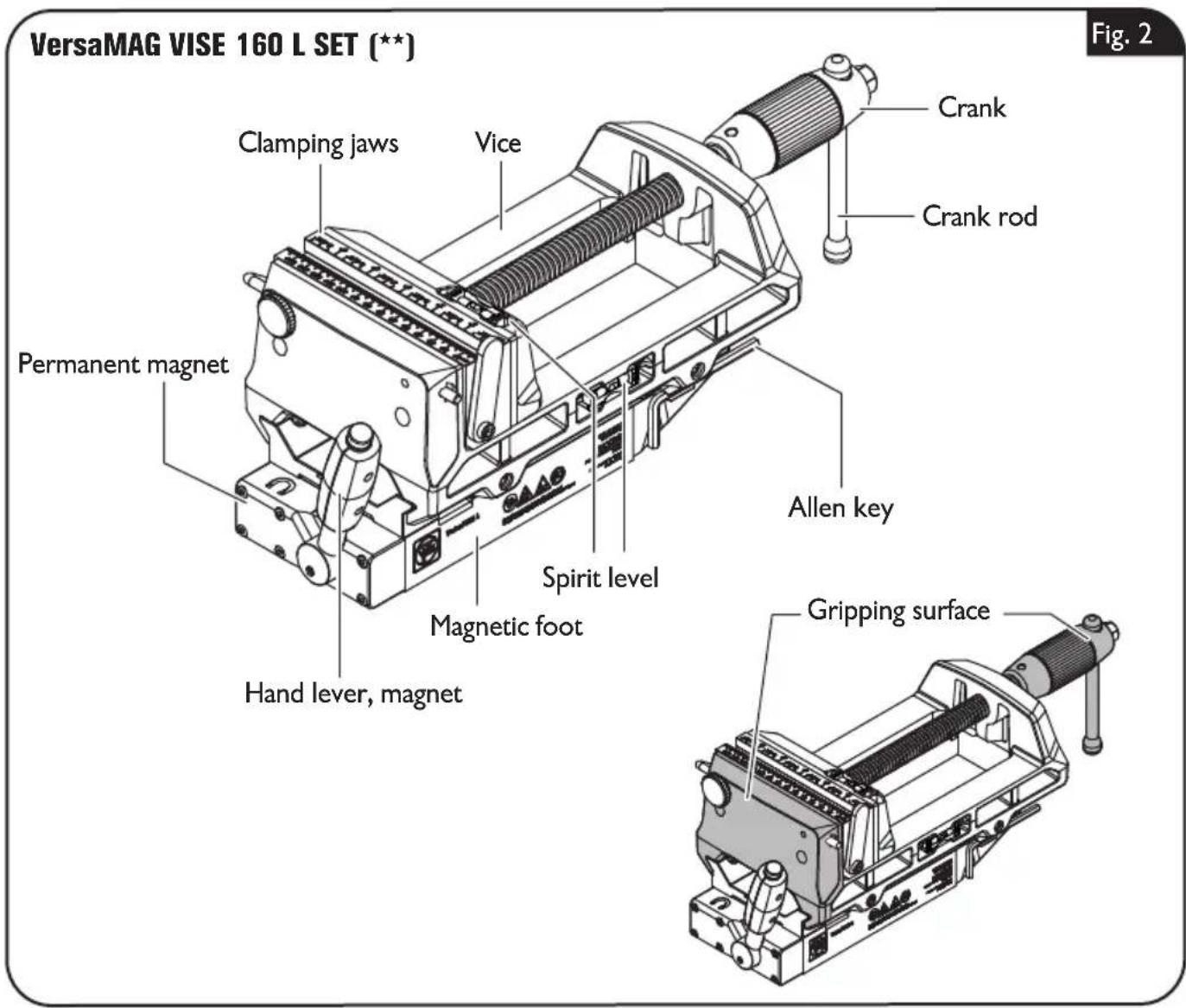
| Supplied accessories | Spirit level, hex key, tension strap; for L: chip tray and stops |
| Regular maintenance | Lubrication of sliding surfaces, checking screw tightness, replacement of jaws and stops |
| Wear check | Check the notches of the magnetic base before each use; replace if visible wear |
| Wear parts replaceable by user | Clamping jaws, stops, chip tray |
| Safety | Do not use near pacemakers; keep away from magnetic storage media; use the tension strap; do not use on surfaces >80 °C |
| Warranty | According to applicable legal regulations and FEIN warranty statement |
Frequently Asked Questions - VersaMAG Fein
User questions about VersaMAG Fein
0 question about this device. Answer the ones you know or ask your own.
Ask a new question about this device
Download the instructions for your Clamp in PDF format for free! Find your manual VersaMAG - Fein and take your electronic device back in hand. On this page are published all the documents necessary for the use of your device. VersaMAG by Fein.
USER MANUAL VersaMAG Fein
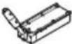
natural_image
Two industrial hydraulic cranes with visible springs and fasteners, shown from different angles (no text or symbols)3 41 01 424 06 0 2025-10-27
| VersaMAG S (**) VersaMAG L (**) | ||||
 | 9 07 01 003 02 0 | kg | 7,3 | - |
| Ibs | 16.0 | - | ||
| 9 91 00 001 35 7 | kg | - | 16,7 | |
| Ibs | - | 36.8 | ||
 | 3 21 72 050 02 0 | kg | 3,8 | - |
| Ibs | 8.3 | - | ||
| 9 91 00 001 35 8 | kg | - | 6,6 | |
| Ibs | - | 14.5 | ||
 | 9 07 01 005 02 0 | kg | 8,9 | - |
| (250 mm × 250 mm, ∅ 16 mm) | Ibs | 19.5 | - | |
| 9 91 00 001 36 0 | kg | - | 13,8 | |
| (400 mm × 400 mm, ∅ 16 mm) | Ibs | - | 30.4 | |
| 9 91 00 001 36 1 | kg | - | 8,7 | |
| (400 mm × 400 mm, ∅ 28 mm) | Ibs | - | 19.1 | |
 | mm | 105,0 | 160,0 | |
| inch | 4.1 | 6.3 | ||
| T_a | °C | -15 ... +45 | -15 ... +45 | |
| °F | +5 ... +113 | +5 ... +113 | ||


de
23
pt
41
tr
59
sl
77
et
95
en(US)
110
en
26
el
44
hu
62
sr
80
It
98
fr(CA)
132
fr
29
da
47
CS
65
hr
83
lv
101
es(MX)
154
it
32
no
50
sk
68
ru
86
zh(
104
nl
35
SV
53
pl
71
uk
89
ar
109
es
38
fi
56
ro
74
bg
92
natural_image
3D model of a mechanical housing or enclosure with internal components, shown without any text or symbols.VersaMAG S (**)
VersaMAG L (**)
natural_image
Mechanical component diagram showing a lever mechanism with an arrow indicating direction (no text or symbols)VersaMAG S (**)
VersaMAG L (**)
VersaMAG L (**)
natural_image
Mechanical component diagram showing a lever mechanism with an arrow indicating direction (no text or symbols)VersaMAG S (**)
VersaMAG L (**)
VersaMAG L (**)

natural_image
Mechanical clamp device with lever and handle, shown in 3D rendering (no text or symbols)VersaMAG S (**)
VersaMAG L (**)
natural_image
Mechanical assembly diagram showing a piston-cranked clamp mechanism with no visible text or symbolsVersaMAG S (**)
VersaMAG L (**)
natural_image
Mechanical assembly diagram showing a conveyor belt and directional arrows (no text or symbols)VersaMAG S (**)
VersaMAG L (**)
natural_image
Illustration of a hand using a pulley device to lift a weight, with an arrow indicating motion direction (no text or symbols)VersaMAG L (**)
natural_image
Mechanical assembly diagram showing a bracket with internal components and a tool, enclosed in a dashed border (no text or symbols)VersaMAG S (**)
VersaMAG L (**)
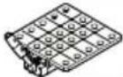
natural_image
Diagram of a mechanical device with a grid panel and lever mechanism, enclosed in a dashed rectangular frame (no text or symbols)VersaMAG S (**)
VersaMAG L (**)
natural_image
Diagram of a mechanical device with grid and lever mechanism, no text or symbols presentVersaMAG S (**)
VersaMAG L (**)
natural_image
Diagram of a robotic arm handling a tray with motion arrows indicating movement (no text or symbols)VersaMAG L (**)
natural_image
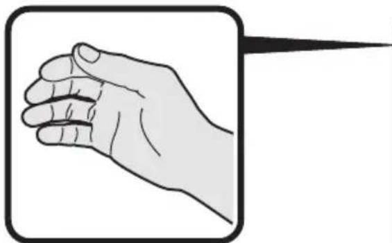
Illustration of a hand with a pointed tip, enclosed in a rounded square frame (no text or symbols)
VersaMAG S (**)
VersaMAG L (**)
VersaMAG S (**)
natural_image
Technical line drawing of a mechanical clamp or fixture with a hand gesture indicator (no text or symbols present)VersaMAG L (**)
natural_image
Illustration of a hand operating a mechanical presser with a magnified inset showing the handle (no text or symbols present)
VersaMAG S (**)
VersaMAG L (**)

Translation of the Original Instructions.
Symbols, abbreviations and terms used.
| Symbol, character Explanation | |
 | Make sure to read the enclosed documents such as the Instruction Manual and the General Safety Instructions. |
 | Observe the instructions in the text or graphic opposite! |
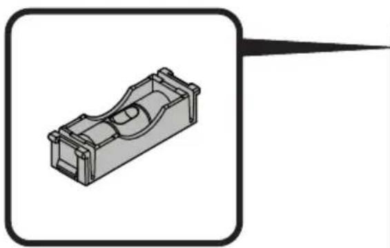
 | Warning against hand injuries! |
 | Do not use magnet near cardiac pacemakers. The magnet generates a field that can impair the function of cardiac pacemakers. |
 | Warning against magnetic field! Keep the magnet away from magnetic data medium and magnetically-sensitive equipment. The effect of the magnets can lead to irreversible data loss. |
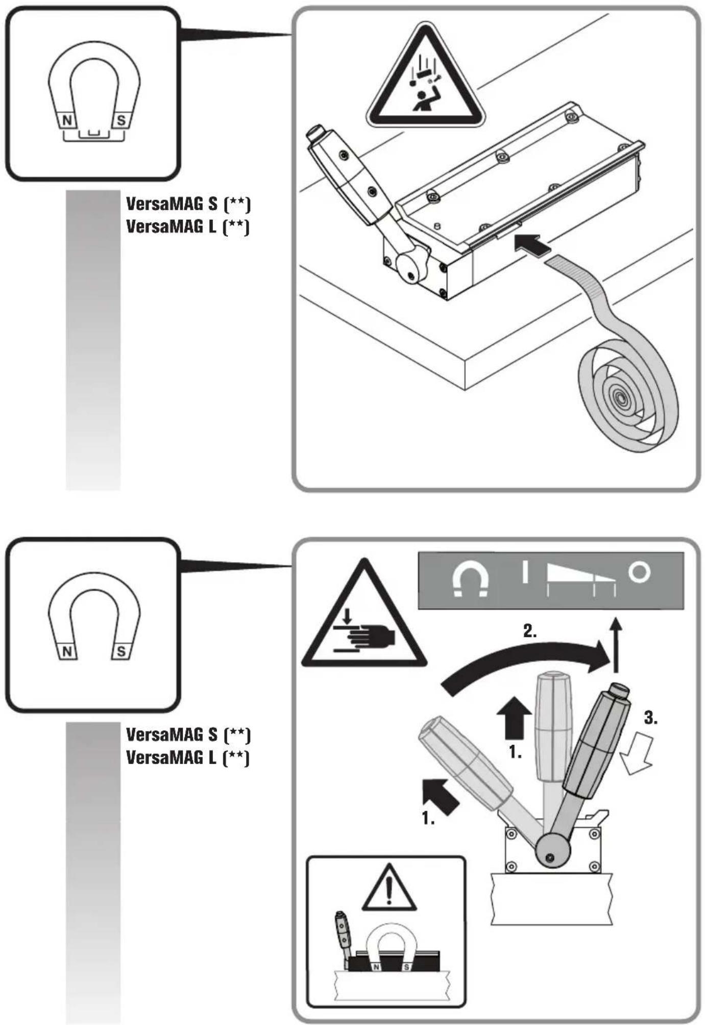
 | Warning against falling objects! |
 WARNING WARNING | This sign indicates a possible dangerous situation that could cause severe or fatal injury. |
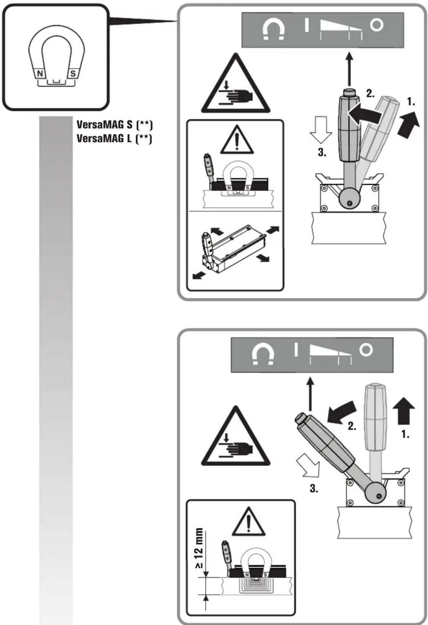
 | Magnet switched on (I), partially magnetized, switched off (O) |
 | Additional information. |
 | See section “Operating Instructions” |
 | Gripping surface |
 | Magnetic holding power sufficient depending on application |
 | Magnetic holding power, insufficient |
| (**) May contain numbers and letters | |
| (Ax - Zx) Marking for internal purposes | |
| Character Unit Explanation | ||
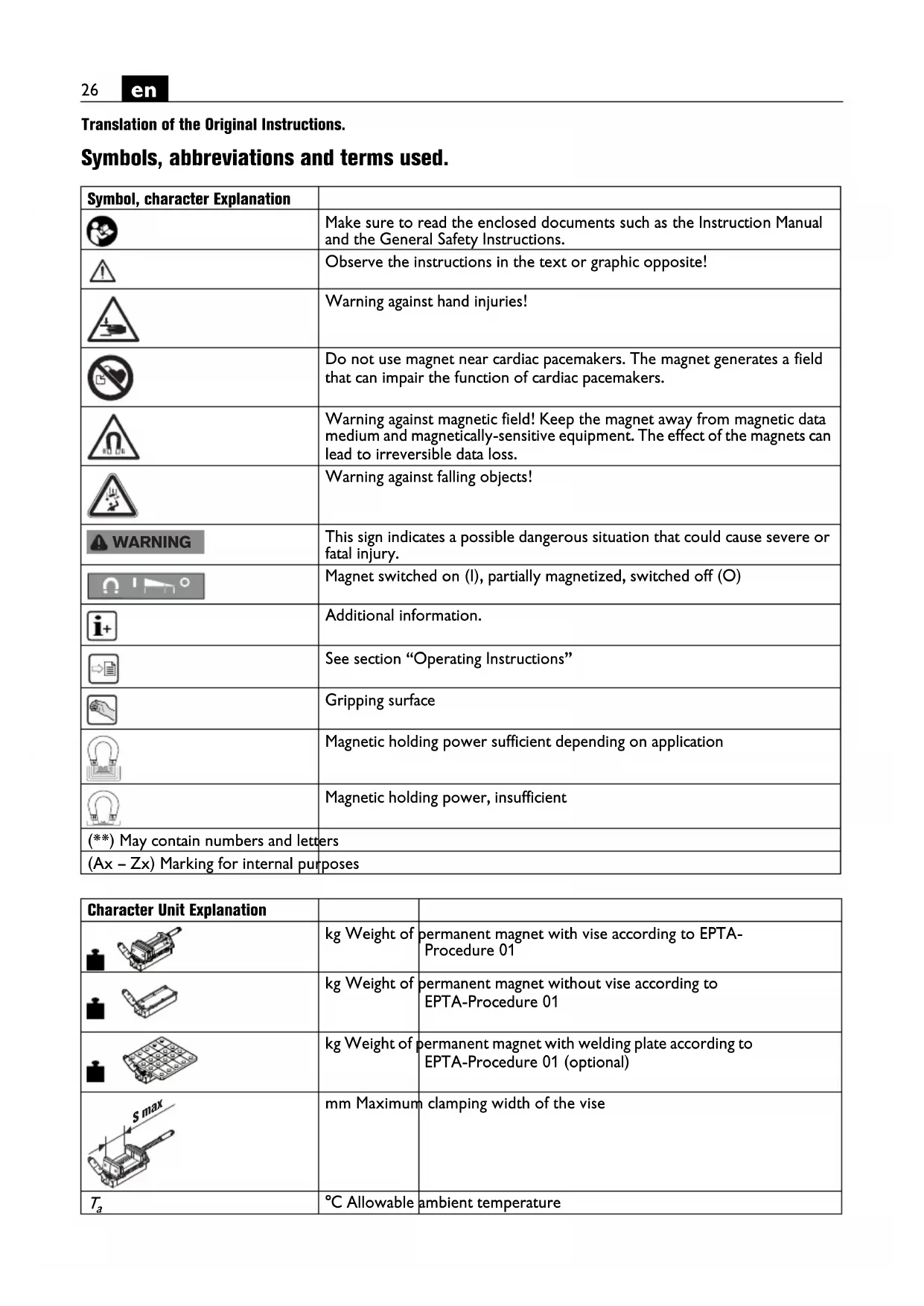
 | kg Weight of | permanent magnet with vise according to EPTA-Procedure 01 |
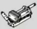
 | kg Weight of | permanent magnet without vise according to EPTA-Procedure 01 |
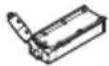
 | kg Weight of | permanent magnet with welding plate according to EPTA-Procedure 01 (optional) |
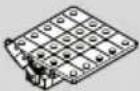
 | mm Maximum | clamping width of the vise |
| T_a | °C Allowable | ambient temperature |
For your safety.
WARNING
Read all safety warnings and all instructions. Failure to follow the
warnings and instructions may result in serious injury. Save all safety warnings and instructions for future reference.

Do not use this product before you have thoroughly read and completely understood this Instruction Manual. The documents mentioned and be kept for later use and enclosed with the act, should it be passed on or sold.
Please also observe the relevant national industrial safety regulations.
Intended use.
VersaMAG permanent magnets with vises ( ^** ) are intended for the following purposes:
- Force-locking clamping of workpieces for machining with hand-held tools and drill presses
- positioning on magnetizable, clean, rust-free, coating-free and ice-free flat materials of 12 mm thickness upward
for commercial use with attachments and accessories approved by FEIN for the product (see www.fein.com) in weather-protected environments. Use only on stable surfaces.
The product may only be used by instructed persons.
All other types of use are considered as not intended for.
The operator is solely liable for any damage caused by use not as intended for.
Foreseeable improper use
For safe operation of the product and to exclude misuse, the following is prohibited:
- Unauthorized modifications
- Drilling holes in the product and the permanent magnet
- Clamping workpieces without force-locking
- Improper use, particularly (but not exclusively) for:
— use on non-magnetizable materials, - fixing workpieces to be processed on the magnetic surface,
— use of non-approved attachments, - use as a lifting magnet,
— use as a step or a handle to assist climbing, - use in machine tools such as milling machines,
- non-observance of the operating instructions,
- exceeding the values specified in this operating manual
Special safety instructions.
Keep work area clean and well lit. Cluttered or dark work areas invite accidents.
Dress properly. Do not wear loose clothing or jewellery. Keep your hair, clothing and gloves away from moving parts. Loose clothes, jewellery or long hair can be caught in moving parts.
Always secure the Product with the supplied safety strap. Keep bystanders away while using the product.
During drilling operations, additionally secure the product against twisting by means of positive locking.
Always clamp workpieces with sufficient clamping force. A workpiece not securely fastened can come loose and cause injuries.
The spindle of the vise must not be driven with electric tools.
Keep the magnet away from persons with cardiac pacemakers.
Use the magnet only at an ambient temperature between -15^ and +45^ .
Do not rivet or screw any name-plates or signs onto the product. This can result in damage to the magnets.
Do not use accessories that have not been especially developed or approved by FEIN.
Transport.
Air freight
Magnetic fields from improperly packaged magnets could affect aircraft navigation equipment. In the worst case, this can lead to an accident.
For air transport, only dispatch magnets in packaging with sufficient magnetic shielding.
Observe the relevant regulations.
Starting Operation.
Before carrying out any work with the product, check that the clamping screws are tight.
Keep bystanders away while using the product.
Operating Instructions.
Use personal protective equipment according to the application.
Use the magnet only on magnetic surfaces with a wall thickness of at least 12 mm.
Pay attention that the set-up surface for the magnetic foot is flat, clean, rust-free and ice-free. Remove varnish, putty/filler layers and other materials. Prevent an air gap between the magnetic foot and the set-up surface. The air gap reduces the magnetic holding power. Do not use this product on hot surfaces >80 ^ , as this will result in a permanent reduction of the magnet holding power.
Only drill workpieces within the clamping range.
When welding, attach the ground connection directly to the workpiece or to the welding plate.
Switching the magnet on.
Clamp and machine workpieces only when the lever position is set to "I".
Troubleshooting.
| Malfunction Meaning Corrective Action | ||
| The movable clamping jaw cannot be moved. | Clamping a workpiece is not possible. | Check the seating of the screws on the bottom side of the clamping jaw. In this case, reduce the tightening torque of the two screws. |
| Lubricate the two sliding surfaces of the vise regularly. | ||
| The magnetic holding power is strongly reduced. | The magnet is defective. Please refer to a FEIN customer service agent. | |
Repair and customer service.
Renew stickers and warning indications on the product when aged and worn.
After several hours of operation, the play in the movable clamping jaw can increase. In this case, tighten the two screws on the bottom side of the movable clamping jaw so that the clamping jaw can be easily moved by hand but does not tilt.
WARNING
Do not remove the permanent magnets under any circumstances, as
they can cause injuries and contusions or bruises.
Have your product repaired only through a qualified repair person and only using original replacement parts. This will ensure that the safety of the product is maintained.
Wear detection on the magnetic foot
Moving the magnetic vise on the set-up surface causes wear to the magnetic foot. This may result in air gaps between the magnetic foot and the set-up surface and the magnetic holding power can be reduced. For checking, the magnetic foot is provided with indentations. Check for wear each time before using the magnetic vise. If one of these indentations is no longer fully visible, the magnetic foot must be replaced (see page 22). Please refer to the FEIN customer service agent under www.fein.com.
Wear parts: Clamping jaws
The current spare parts list of this product can be found on the Internet under www.fein.com.
If required, you can change the following parts yourself:
- Clamping jaws, stops, chip tray
Warranty and liability.
The warranty for the product is valid in accordance with the legal regulations in the country where it is marketed. In addition, FEIN also provides a guarantee in accordance with the FEIN manufacturer's warranty declaration.
The delivery scope of your product may include only a part of the accessories described or shown in this Instruction Manual.
Environmental protection, disposal.
Packaging, worn out products and accessories should be sorted for environment-friendly recycling.
Accessories.
Only use original accessories from FEIN intended for the product. Approved accessories for the product can be found at www.fein.com.
Read all safety warnings and all instructions. Failure to
follow the warnings and instructions may result in serious injury.
Save all safety warnings and instructions for future reference.

Do not use this product before you have thoroughly read and completely understood this Instruction Manual. The documents mentioned should be kept for later use and enclosed with the product, should it be passed on or sold.
Please also observe the relevant national industrial safety regulations.
Safety instructions.
Keep work area clean and well lit. Cluttered or dark work areas invite accidents.
Wear suitable clothing. Do not wear loose clothing or jewelry. Keep your hair, clothing and gloves away from moving parts. Loose clothes, jewelry or long hair can be caught in moving parts.
Always secure the Product with the supplied safety strap. Keep bystanders away while using the product.
Secure the product against twisting during drilling operations by means of a form-fit connection.
Always clamp workpieces with sufficient clamping force. A workpiece not securely fastened can come loose and cause injuries.
The spindle of the vise must not be driven with electric tools.
Keep the magnet away from persons with cardiac pacemakers.
Use the magnet only at an ambient temperature between -15^ and +45^ .
Do not rivet or screw any name-plates or signs onto the product. This can result in damage to the magnets.
Do not use accessories that have not been especially developed or approved by FEIN.
Transport.
Air freight
Magnetic fields from improperly packaged magnets could affect aircraft navigation equipment. In the worst case, this can lead to an accident.
For air transport, only dispatch magnets in packaging with sufficient magnetic shielding.
Observe the relevant regulations.
Intended Use.
VersaMAG permanent magnets with vise ( ^** ) are intended for the following purposes:
- Force-fit clamping of workpieces for machining with hand-held tools and box column drills
- Positioning on magnetizable, clean, rust-free, coating-free, ice-free, and flat materials with a thickness of 12 mm or more
For commercial use in weather-protected environments using the attachments and accessories approved by FEIN for the product (see www.fein.com). Only use the product on a stable surface.
The product may only be used by trained personnel.
All other types of use are considered as not intended for.
The operator is solely liable for any damage caused by use not as intended for.
Foreseeable improper use
For safe operation of the product and to exclude misuse, the following is prohibited:
- Unauthorized modifications
- Drilling holes in the product and the permanent magnet
- Clamping workpieces without frictional locking
- Improper use, including but not limited to:
- use on non-magnetizable materials;
-
fixing workpieces to be machined to the magnetic surface;
-
use of non-approved attachments;
— use as a lifting magnet; - use as a step or handle serving as a climbing aid;
- use in machine tools such as milling machines;
- Failure to observe the operating instructions
- Exceeding the values specified in this Instruction Manual
Symbols.
| Symbol, character Explanation | |
 | Make sure to read the enclosed documents such as the Instruction Manual and the General Safety Instructions. |
 | Observe the instructions in the text or graphic opposite! |
 | Warning against hand injuries! |
 | Do not use magnet near cardiac pacemakers. The magnet generates a field that can impair the function of cardiac pacemakers. |
 | Warning against magnetic field! Keep the magnet away from magnetic data medium and magnetically-sensitive equipment. The effect of the magnets can lead to irreversible data loss. |
 | Warning against falling objects! |
 | This sign warns of a directly imminent, dangerous situation. A false reaction can cause a severe or fatal injury. |
 | This sign indicates a possible dangerous situation that could cause severe or fatal injury. |
 | This sign warns of a possible dangerous situation that could cause injury. |
 | Magnet switched on (I), partially magnetized, switched off (O) |
 | Magnetic holding power sufficient depending on application |
 | Magnetic holding power, insufficient |
| (**) may contain numbers and letters | |
| (Ax - Zx) Marking for internal purposes | |
| Character Unit Explanation | ||
| °F Allowable ambient temperature | ||
| m | Ibs Mass | |
| lin Length, width, height, depth, diameter or thread | ||
| m, s, kg, A, mm, V, W, Hz, N, °C, dB, min, m/s2 | Basic and derived units of measurement from the international system of units SI. | |
Technical description and specifications.
The delivery scope of your product may include only a part of the accessories described or shown in this Instruction Manual.
| Type | Order number | VersaMAG S (**) | VersaMAG L (**) |
| Weight of permanent magnet with vise according to EPTA-Procedure 01 | 9 07 01 003 02 0 | 16.0 lbs | - |
| 7.3 kg | - | ||
| 9 91 00 001 35 7 | - | 36.8 lbs | |
| - | 16.7 kg | ||
| Weight of permanent magnet without vise according to EPTA-Procedure 01 | 3 21 72 050 02 0 | 8.3 lbs | - |
| 3.8 kg | - | ||
| 9 91 00 001 35 8 | - | 14.5 lbs | |
| - | 6.6 kg | ||
| 9 07 01 005 02 0(250 mm x 250 mm,∅ 16 mm) | 19.5 lbs | - | |
| 8.9 kg | - | ||
| Weight of permanent magnet with welding plate according to EPTA-Procedure 01 (optional) | 9 91 00 001 36 0(400 mm x 400 mm,∅ 16 mm) | - | 30.4 lbs |
| - | 13.8 kg | ||
| 9 91 00 001 36 1(400 mm x 400 mm,∅ 28 mm) | - | 19.1 lbs | |
| - | 8.7 kg | ||
| Maximum clamping width of the vise | 4.1 in | 6.3 in | |
| 105.0 mm | 160.0 mm | ||
| Allowable ambient temperature | 5 °F ... 113 °F | 5 °F ... 113 °F | |
| -15 °C ... +45 °C | -15 °C ... +45 °C |
Working instructions.
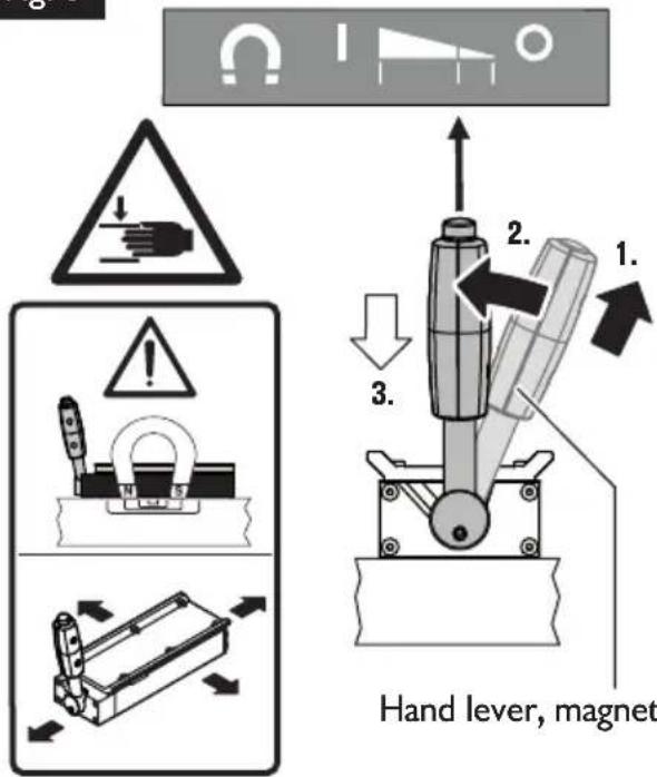
For switching the magnet ON (figure 3).
Before carrying out any work with the product, check that the clamping screws are tight. Keep bystanders away while using the product.
Use personal protective equipment according to the application.
Only use the magnet on magnetic surfaces with a wall thickness of at least 12 mm.
Pay attention that the set-up surface for the magnetic foot is flat, clean, rust-free and ice-free. Remove varnish, putty/filler layers and other materials. Prevent an air gap between the magnetic foot and the set-up surface.
The air gap reduces the magnetic holding power.
Do not use this product on hot surfaces >80^ , as this will result in a permanent reduction of the magnet holding power.
Only clamp and machine workpieces when the lever is set to "I".
Fig. 3
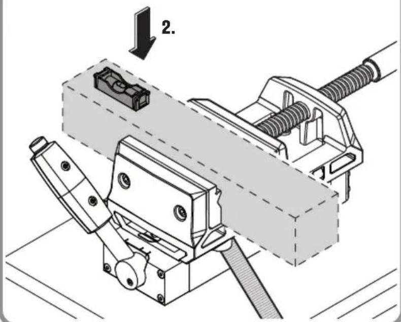
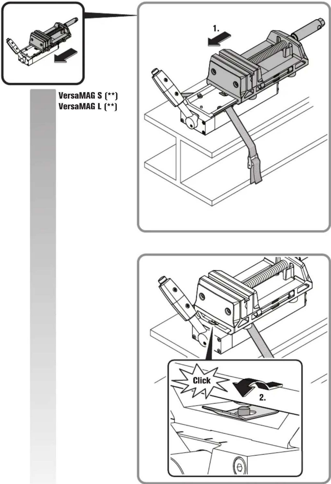
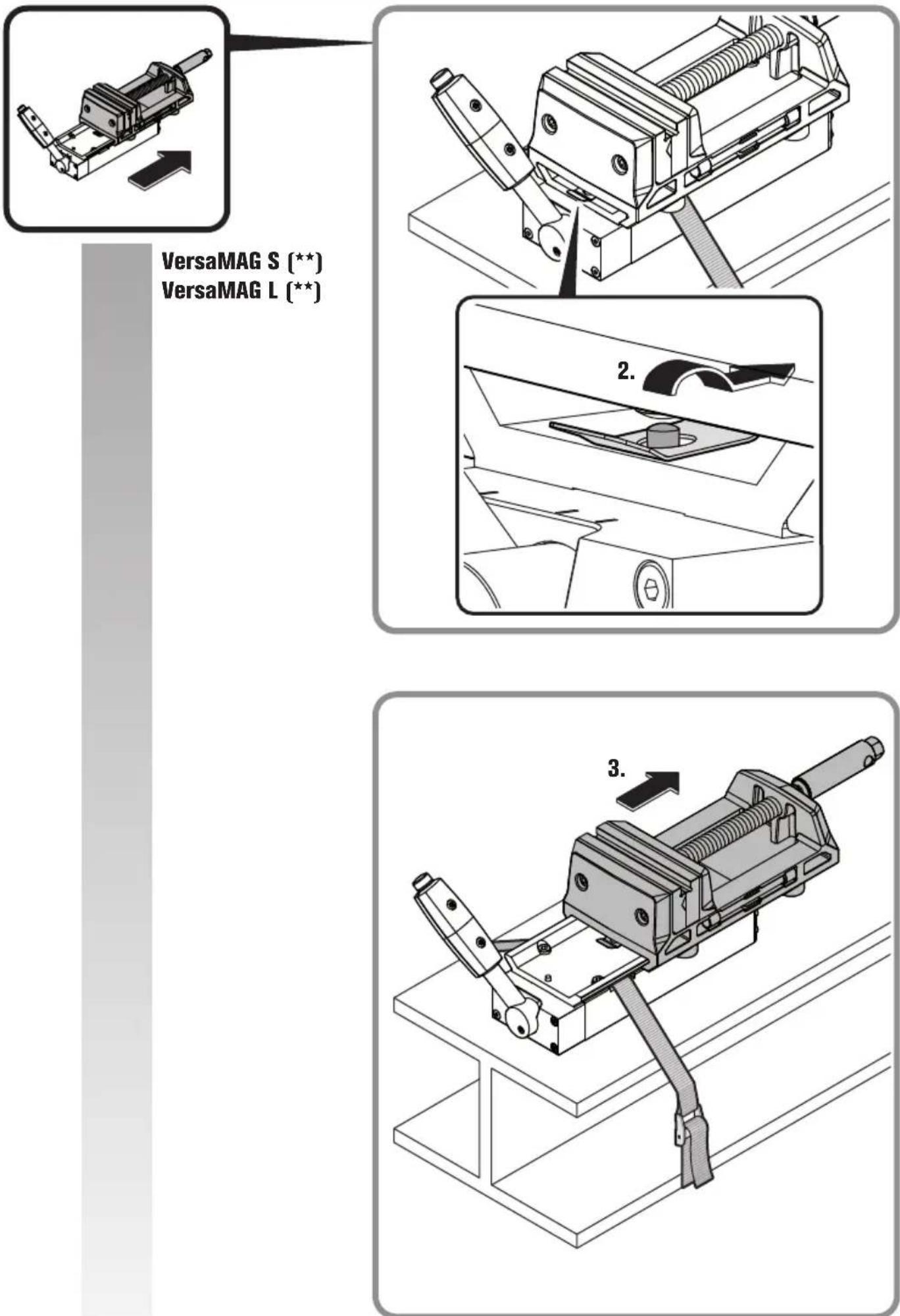
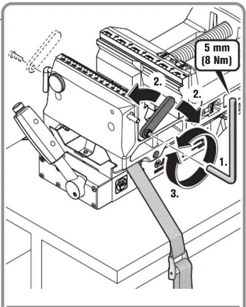
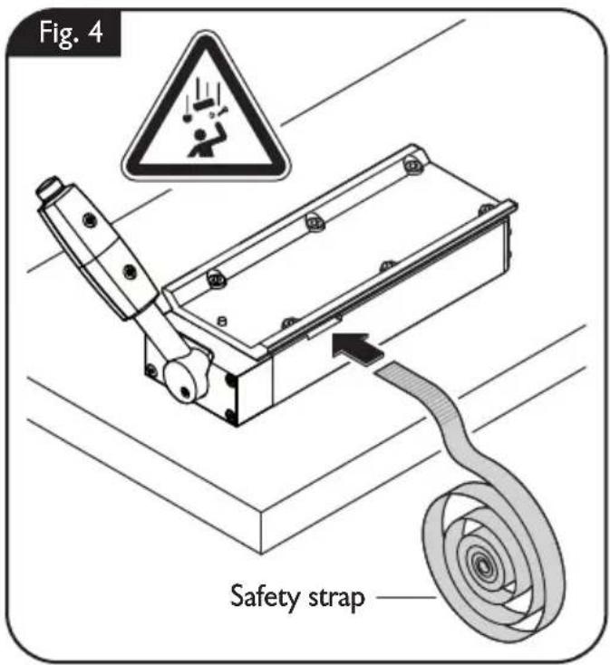
Fastening the measuring tool safety strap (figure 4).
Always secure the product with the supplied safety strap.
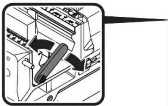
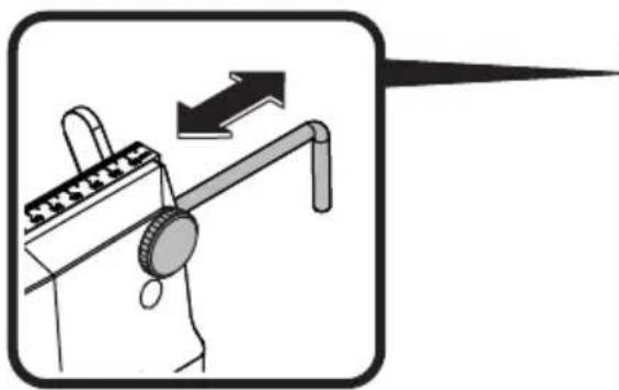
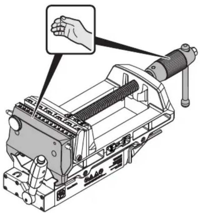
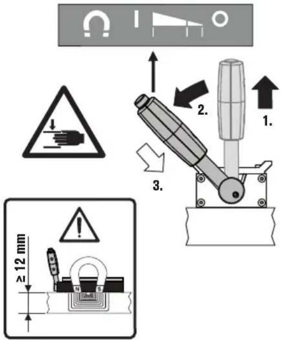
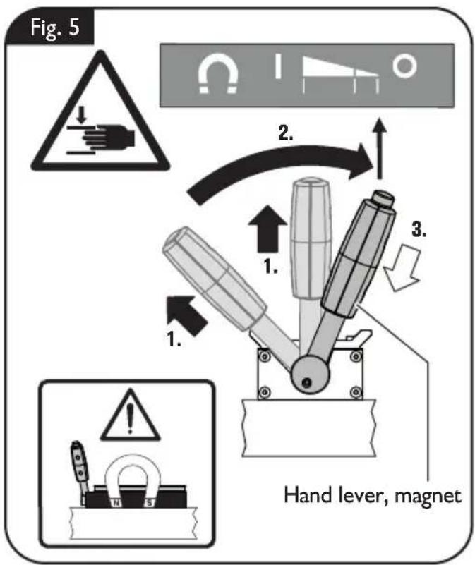
Switching off the magnetization (figure 5).
Slide the handle-lever sleeve upward. Set the hand lever to "O".
The handle-lever sleeve automatically retracts back to the starting position.
Corrective Action.
| Malfunction Meaning | Corrective action | |
| The movable clamping jaw cannot be moved. | Clamping a workpiece is not possible. | Check the seating of the screws on the bottom side of the clamping jaw. In this case, reduce the tightening torque of the two screws. |
| Lubricate the two sliding surfaces of the vise regularly. | ||
| The magnetic holding power is strongly reduced. | The magnet is defective. Please refer to a FEIN customer service agent. | |
Assembly instructions.
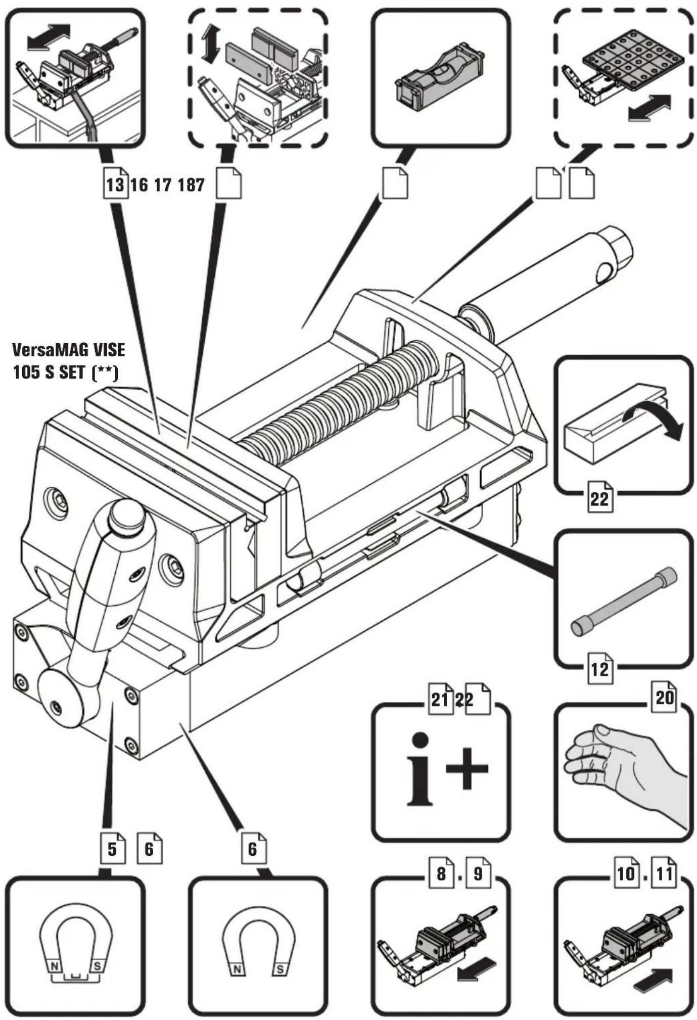
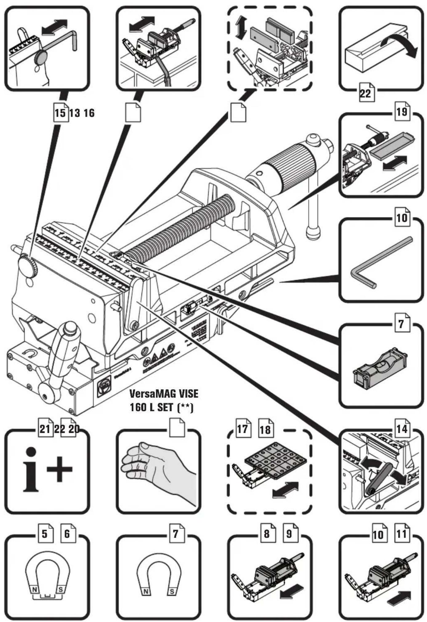
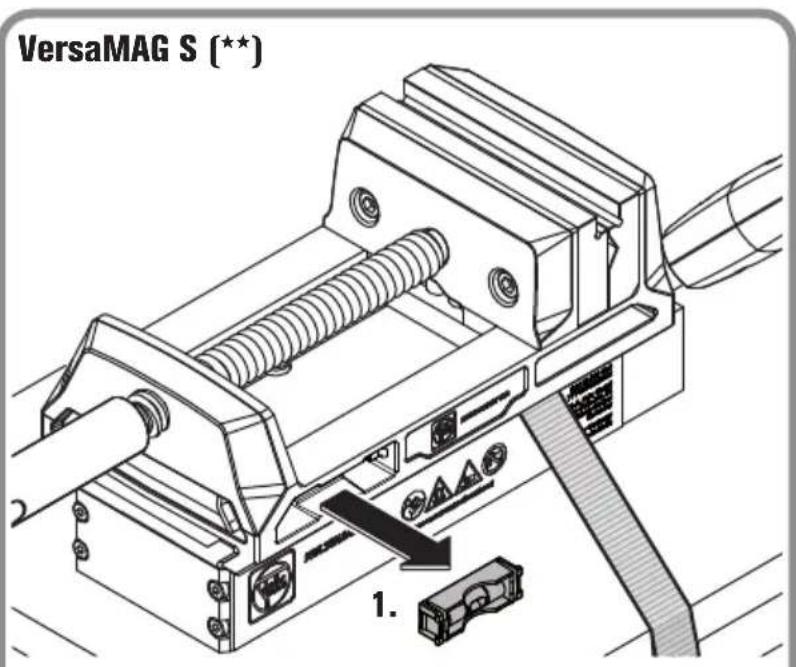
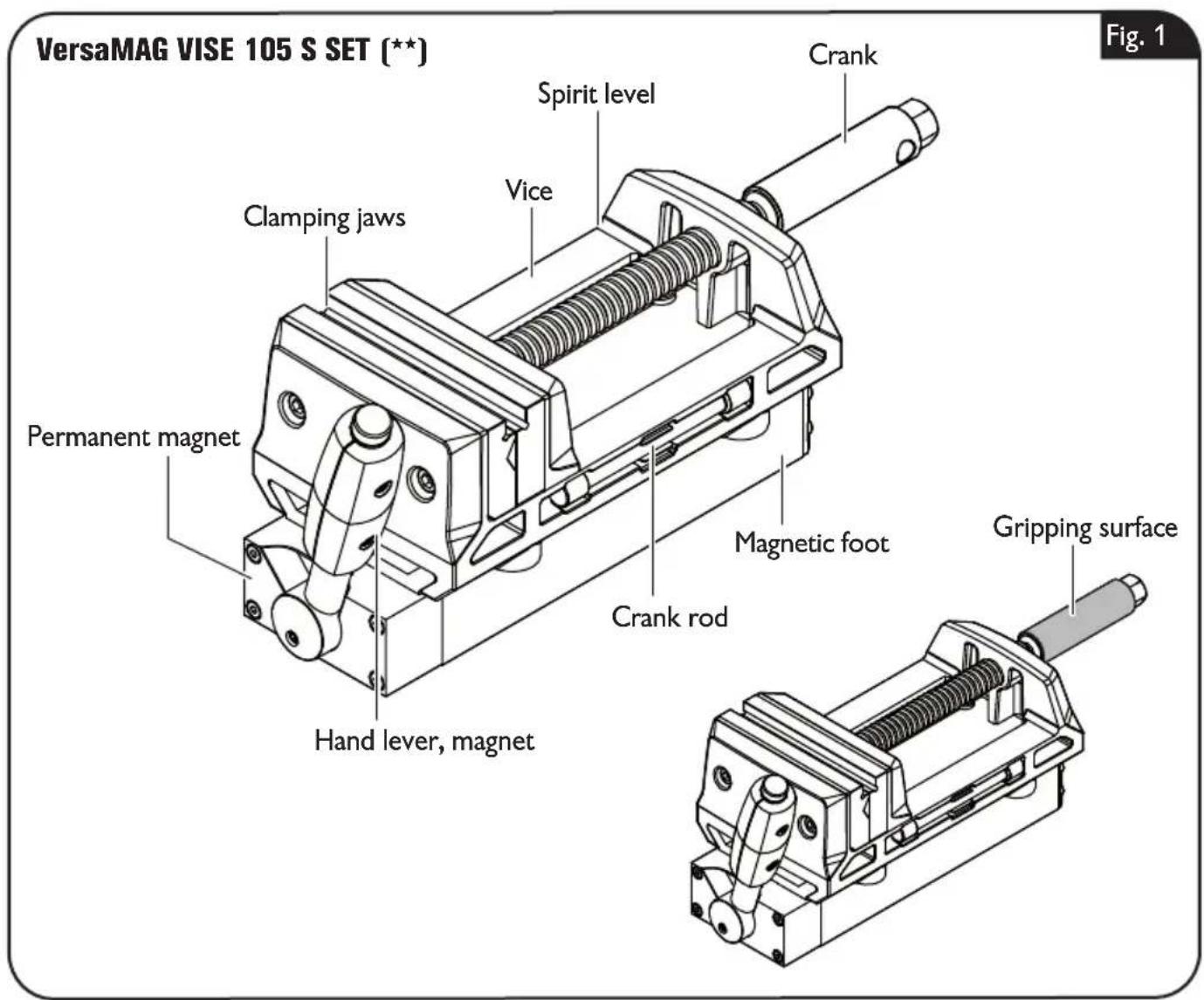
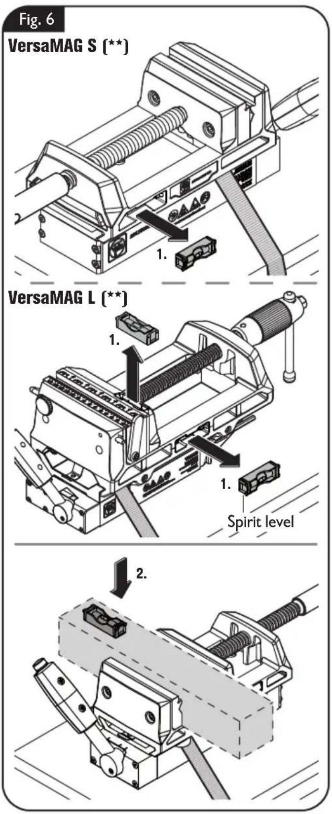
Spirit level (figure 6).
A spirit level is supplied with the product; it can be used, for example, to check the alignment of a workpiece.
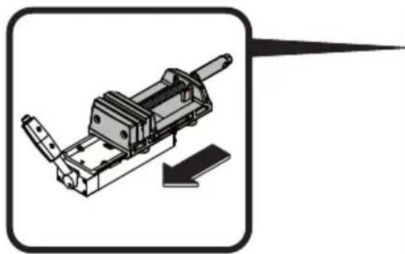
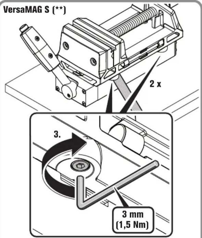
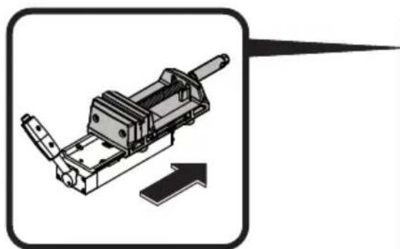
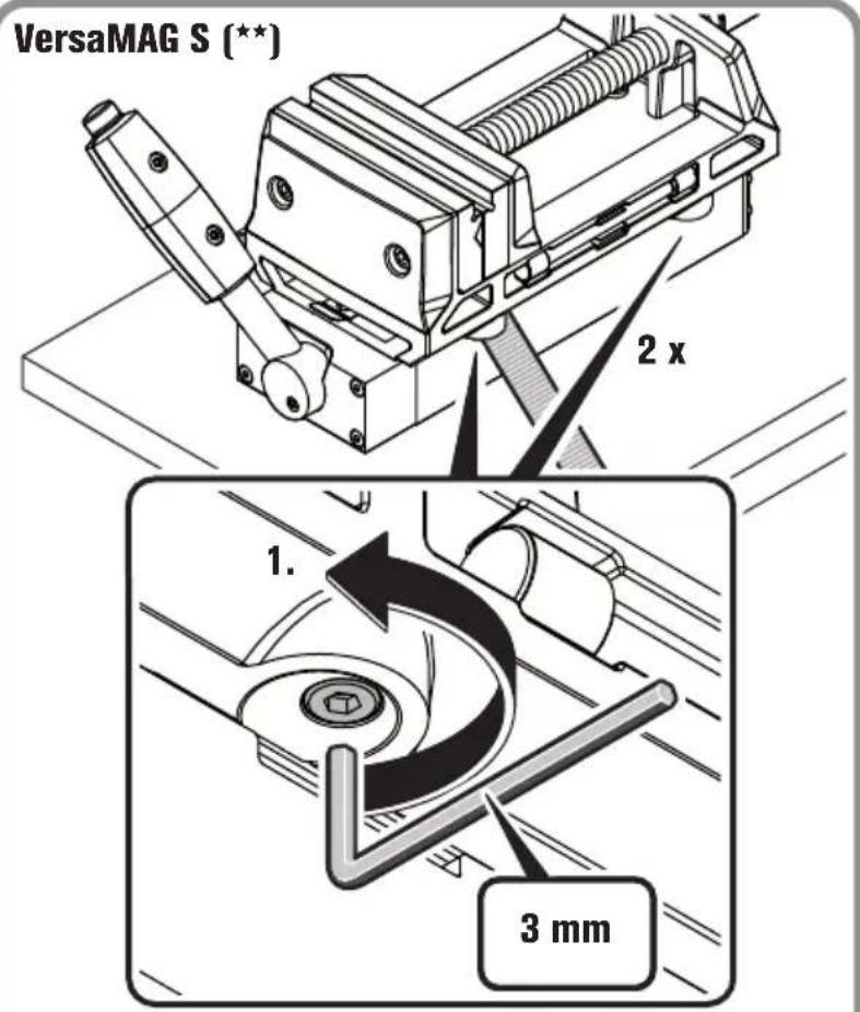
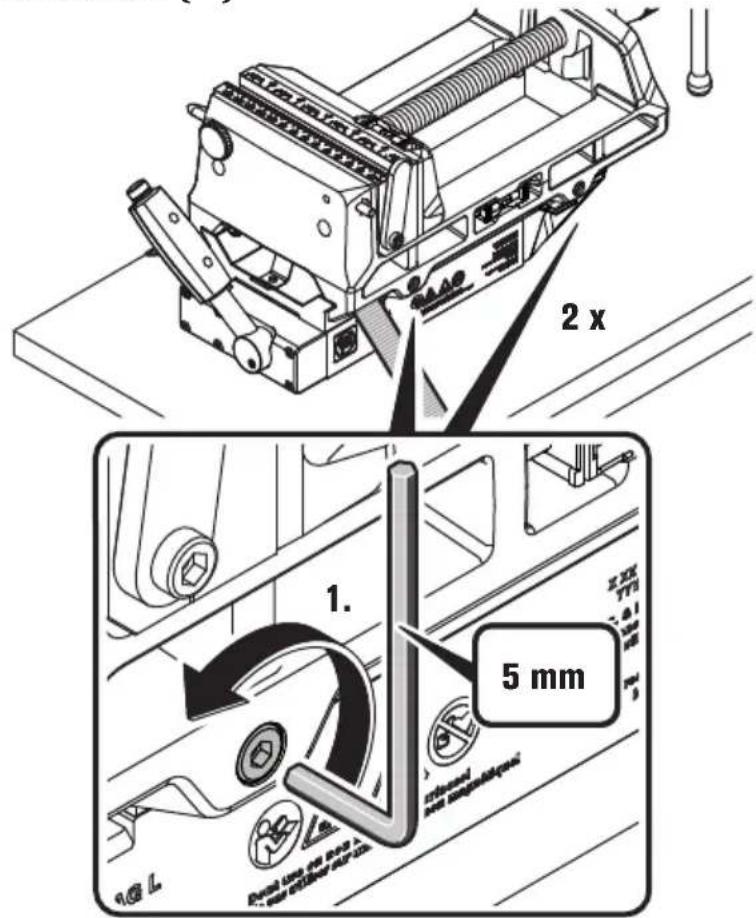
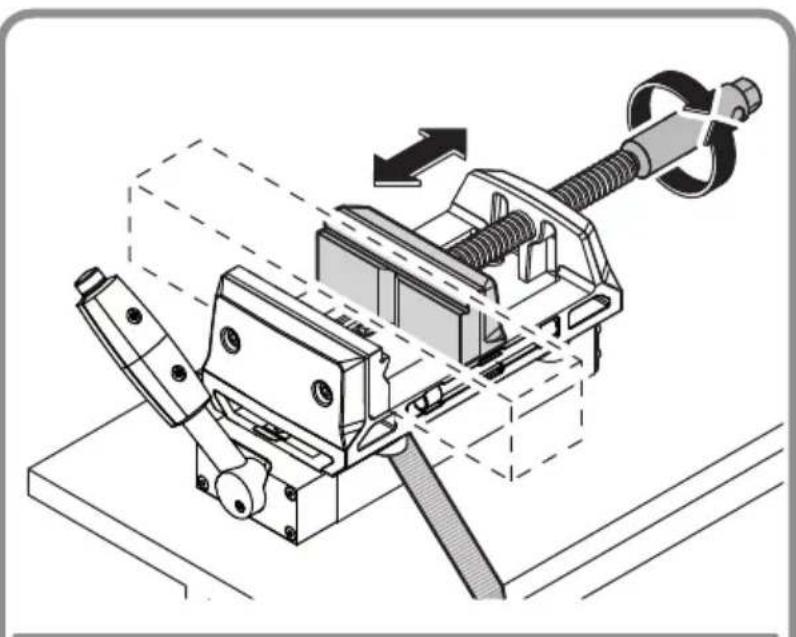
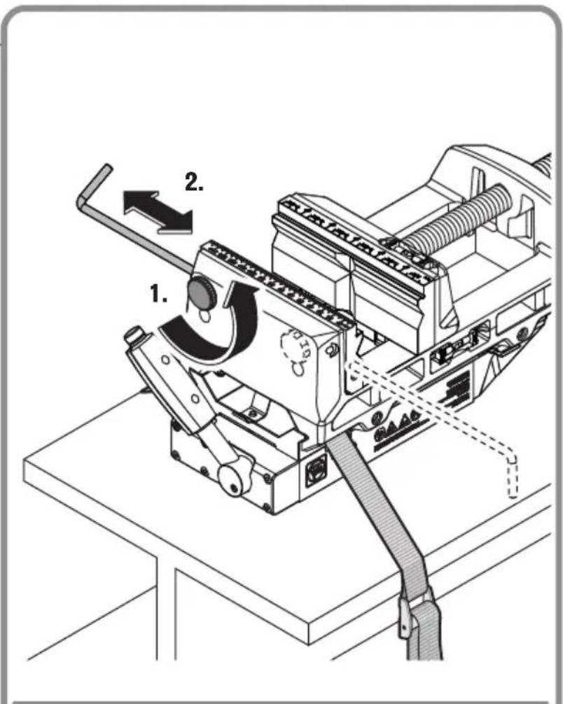
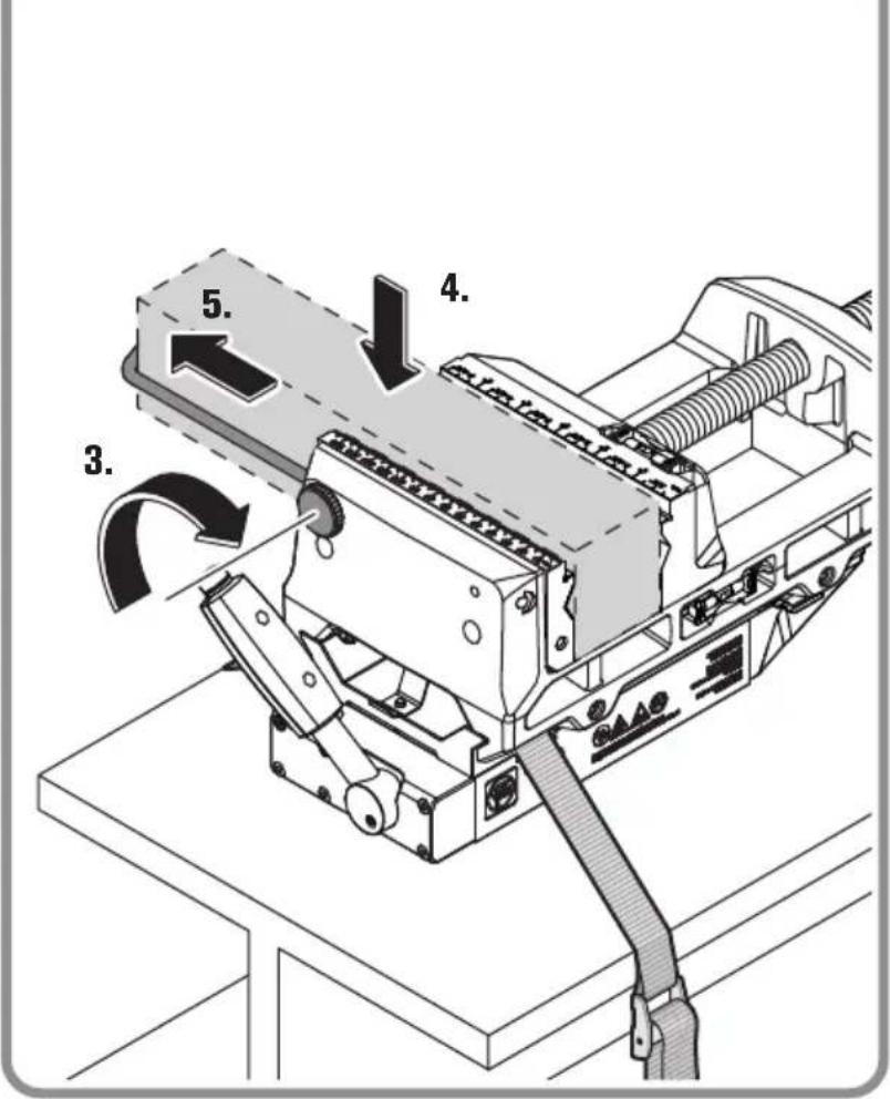
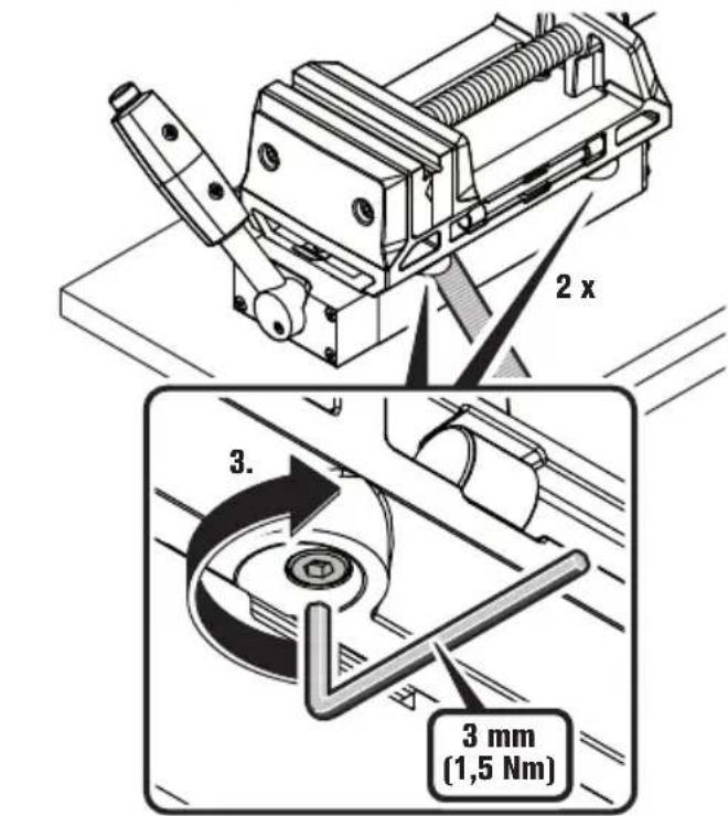
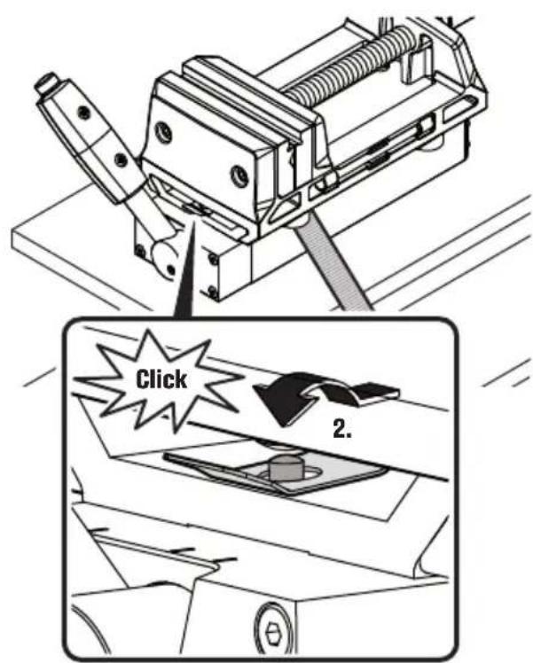
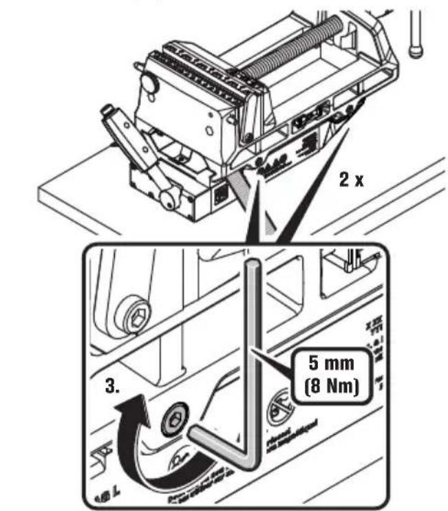
Fastening the vise to the permanent magnet (figure 7).
Slide the vise onto the permanent magnet until the fastening bracket engages over the fastening bolt.
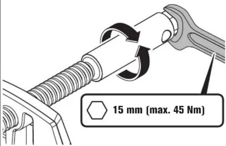
Tighten the hexagon socket screws.
Fig. 7
natural_image
Mechanical assembly diagram showing a clamping device mounted on a base plate, with no visible text or symbols.VersaMAG S (**)
VersaMAG L (**)
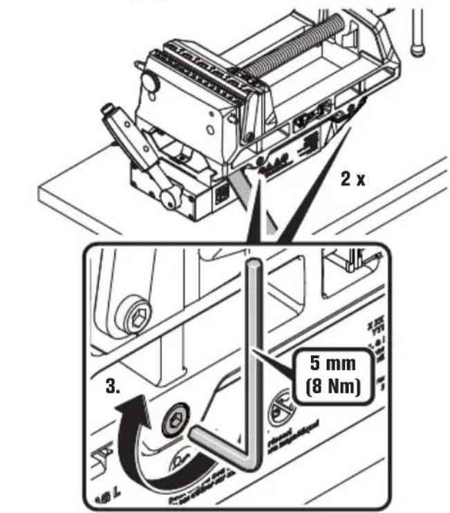
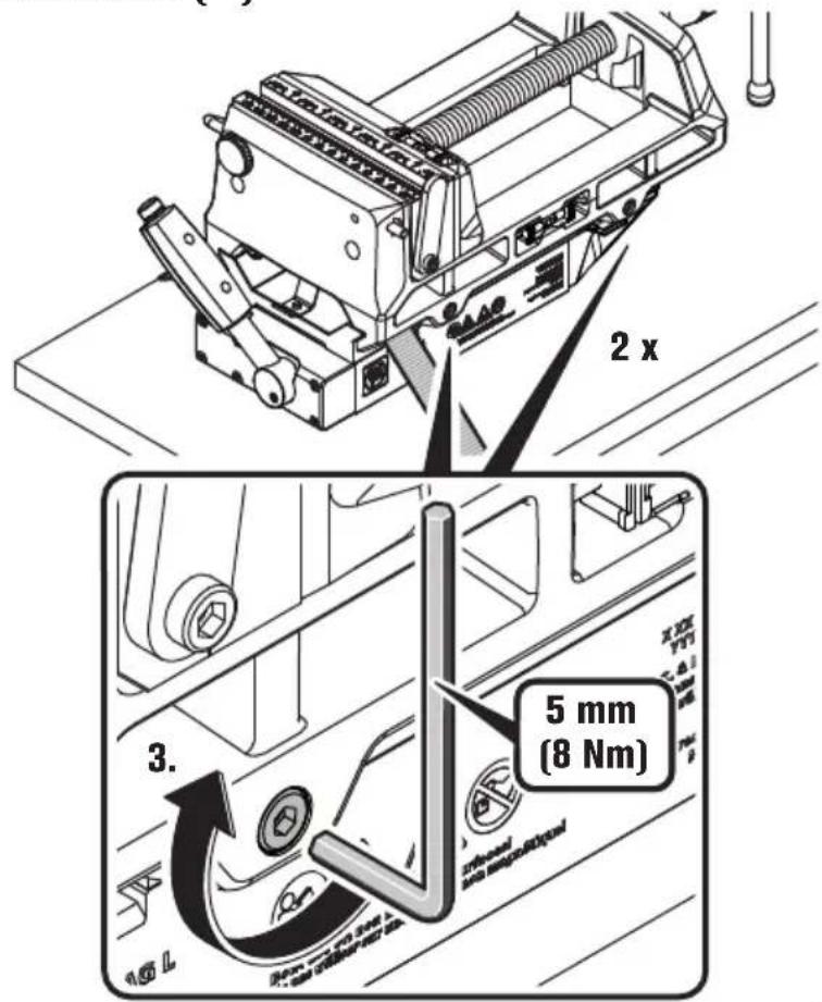
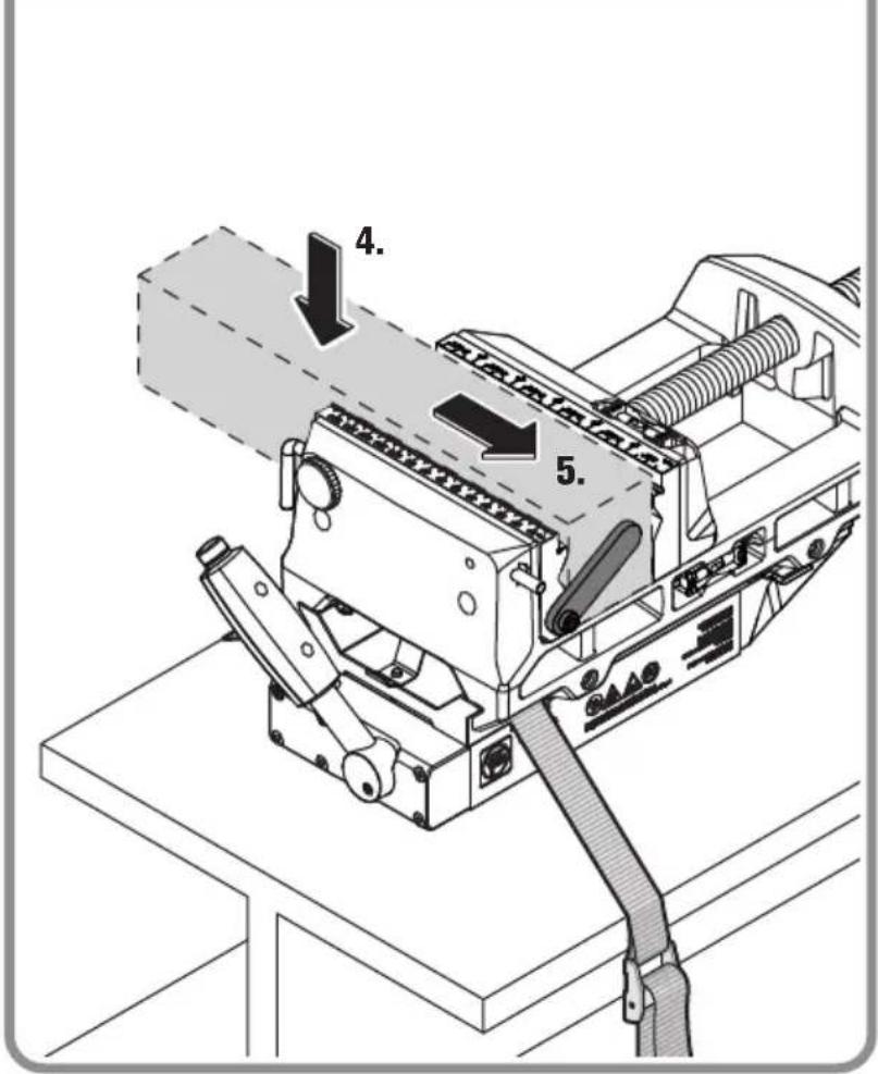
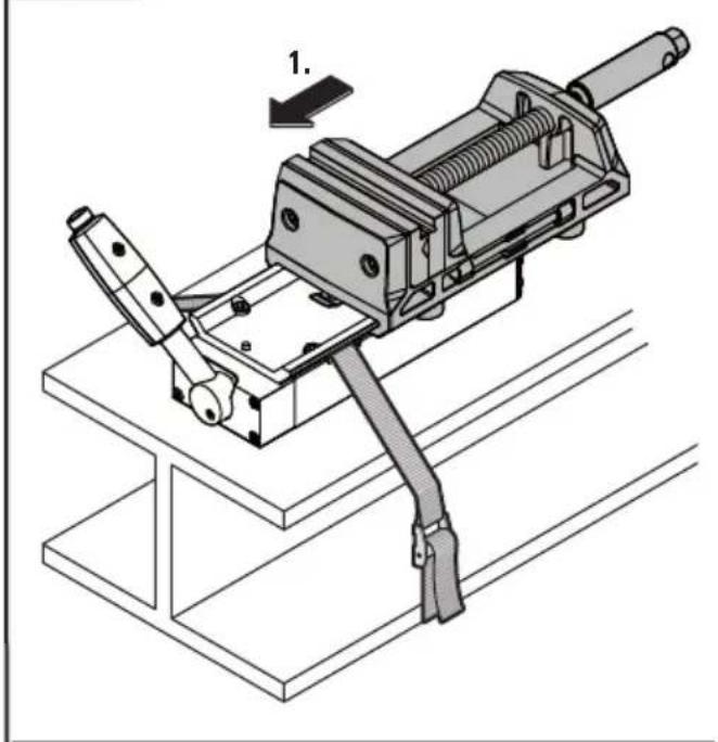
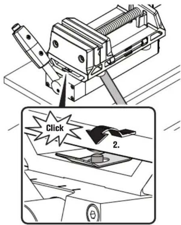
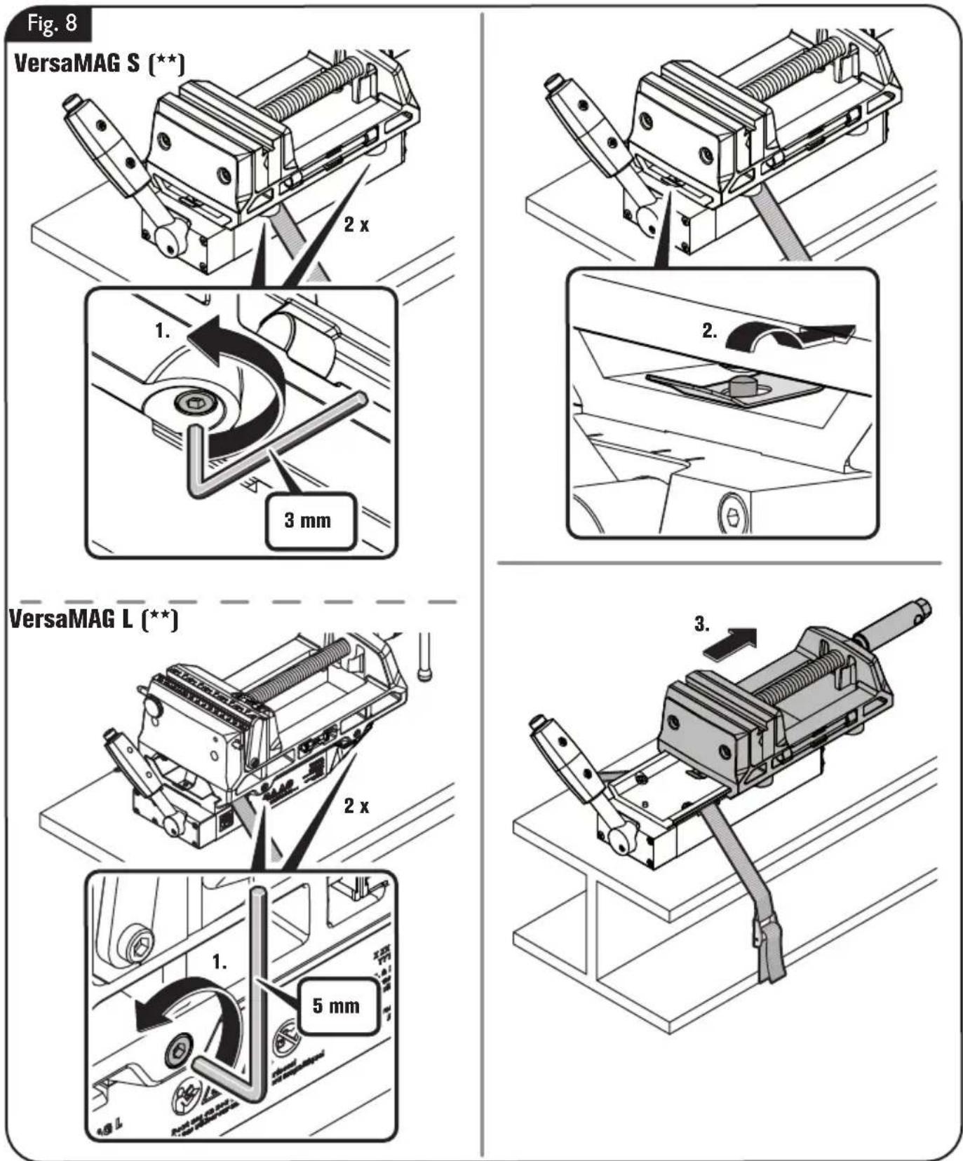
Removing the permanent magnet from the vise (figure 8).
Loosen the hexagon socket screws.
Push the fastening bracket up and slide the vise away so that the bracket goes over the fastening bolt.
Pull the vise off the permanent magnet.
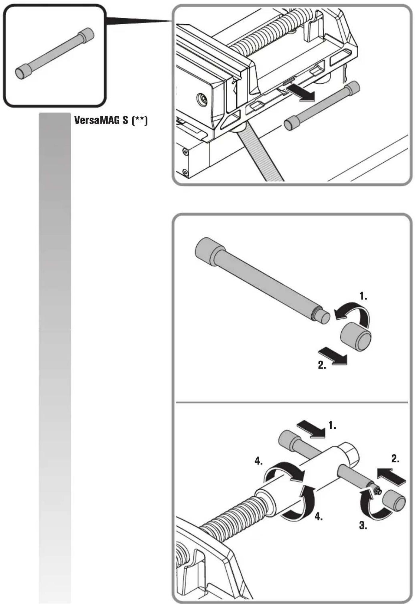
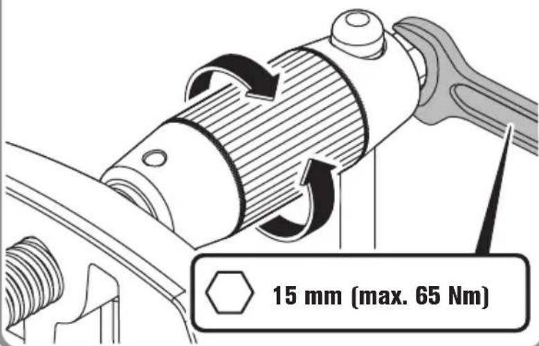
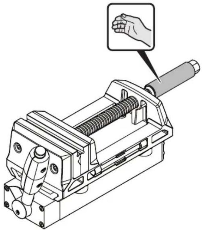
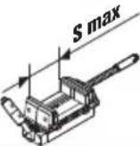
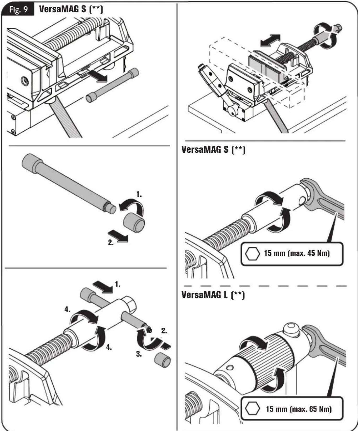
Clamping a workpiece (figure 9).
To clamp a workpiece, use the supplied crank rod or an open-end wrench.
Remove the supplied crank rod from the vise and mount it through the bore at the crank end. Clamp the workpiece.
Or turn the crank using an open-end wrench. Clamp the workpiece.
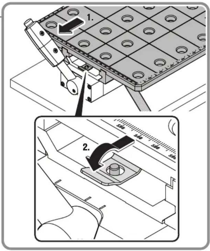
Mounting the workpiece stop (VersaMAG L [\*\*])(figure 10).
Use the workpiece stop for precise positioning and fixation of workpieces with repeat accuracy.
![Fein VersaMAG - Mounting the workpiece stop (VersaMAG L [\*\*])(figure 10). - 1](/content/2026/03/494184/images/4d4b98864747bc5e00b3204a001018be92aca8257d622099f80830e257eb1936.jpg)
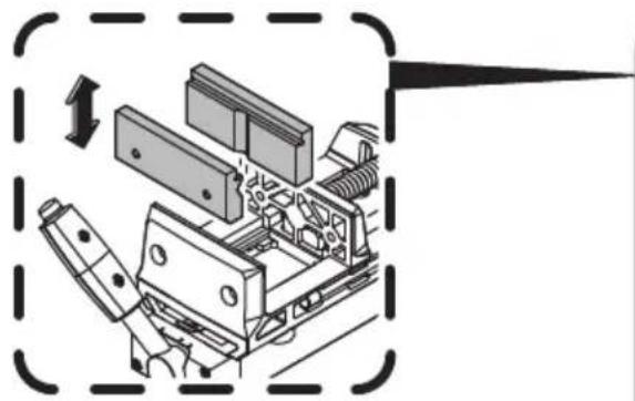
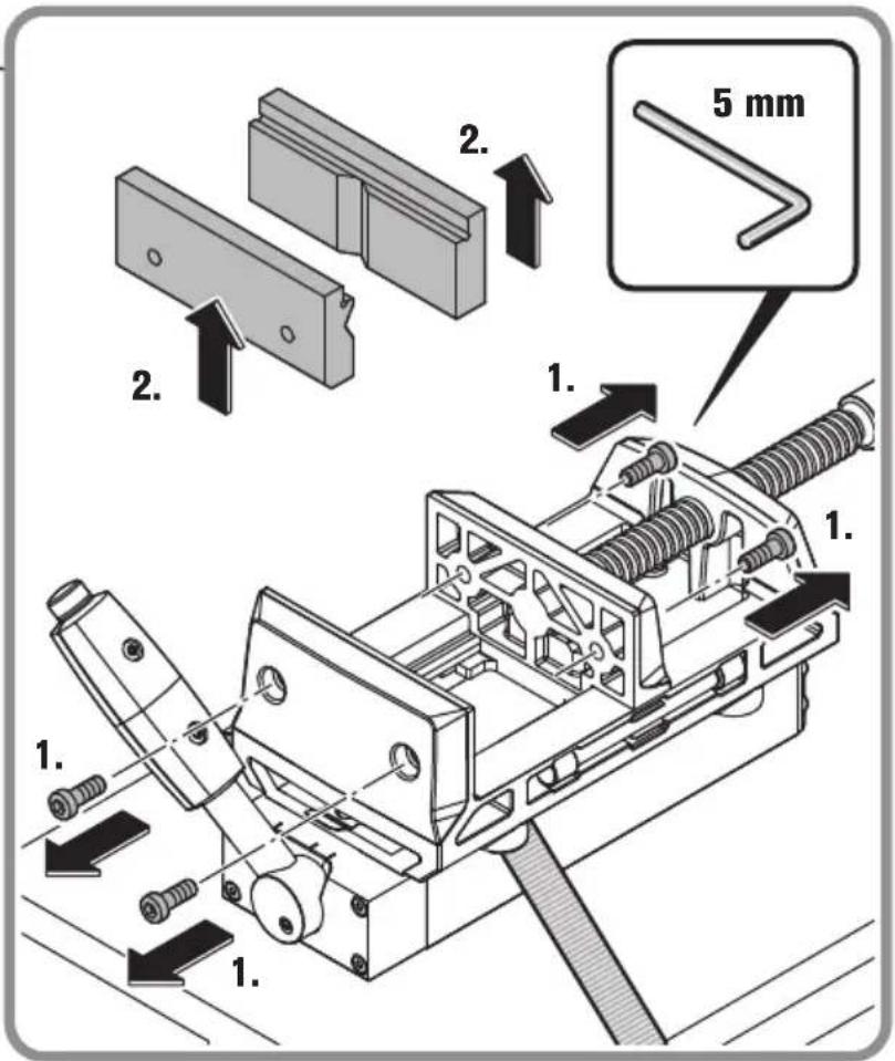
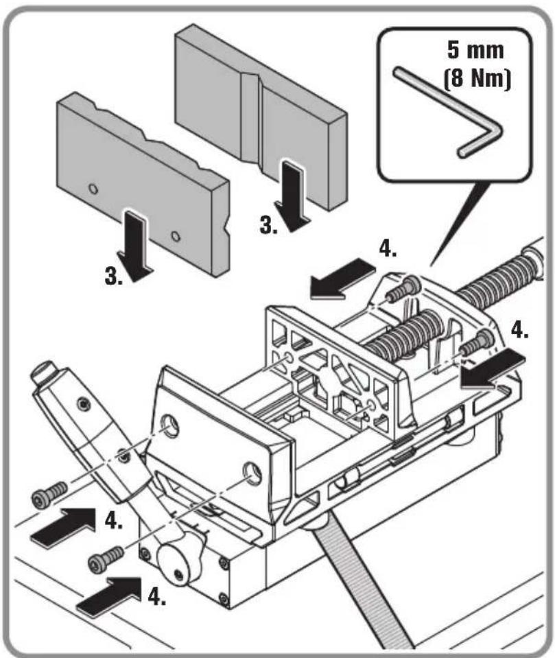
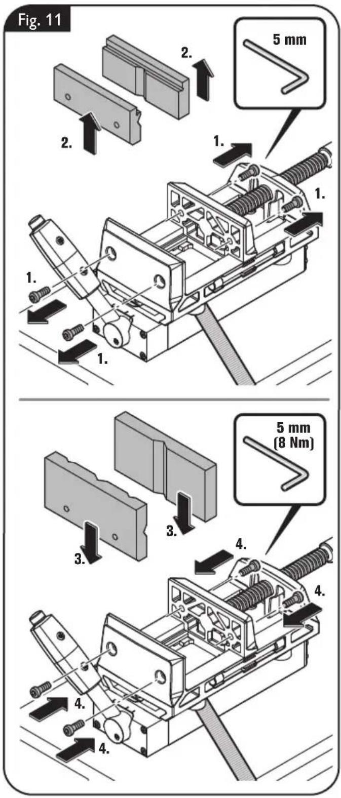
Replacing clamping jaws (figure 11).
Remove the 4 hexagon socket screws.
Remove the clamping jaws.
Position the replacement clamping jaws in place.
Mount the 4 hexagon socket screws again.
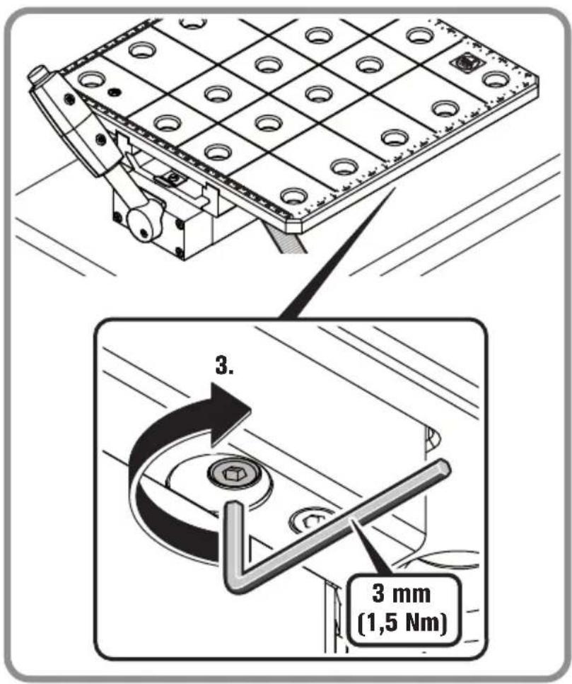
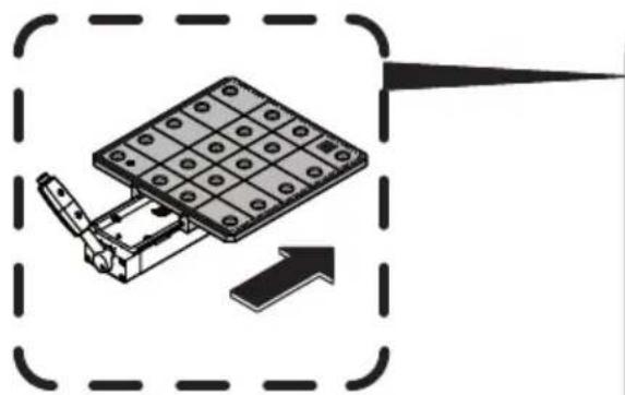
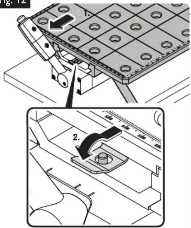
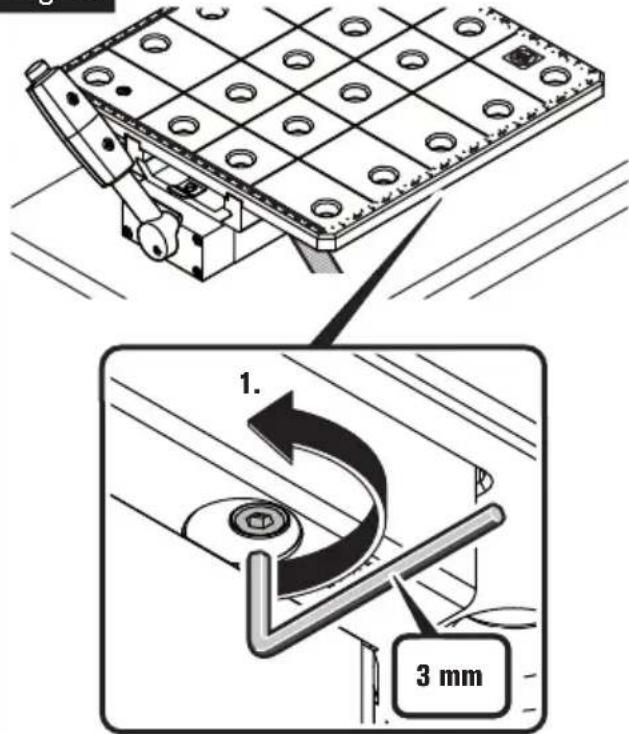
Mounting the welding plate (figure 12).
Slide the welding plate onto the permanent magnet until the fastening bracket engages over the fastening bolt.
Tighten the hexagon socket screws.
Fig. 12

natural_image
Technical line drawing of a mechanical assembly with grid pattern and mounting bracket (no text or symbols)
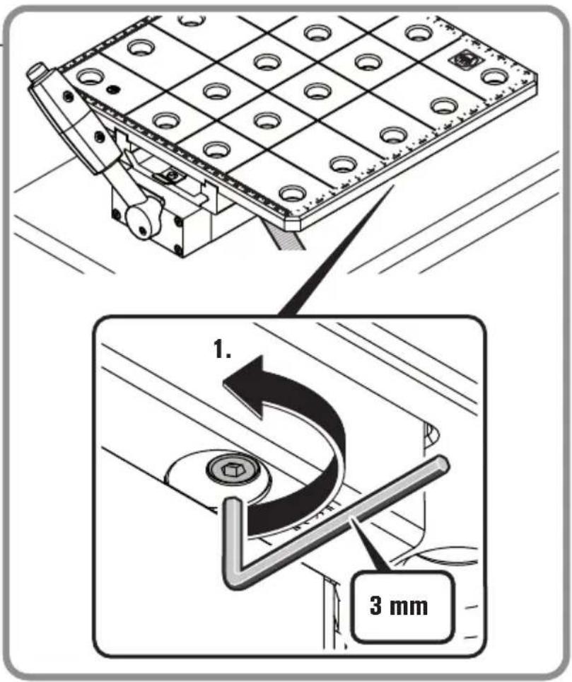
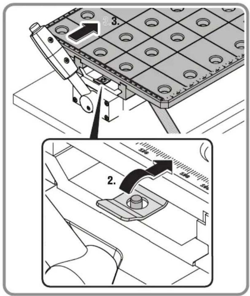
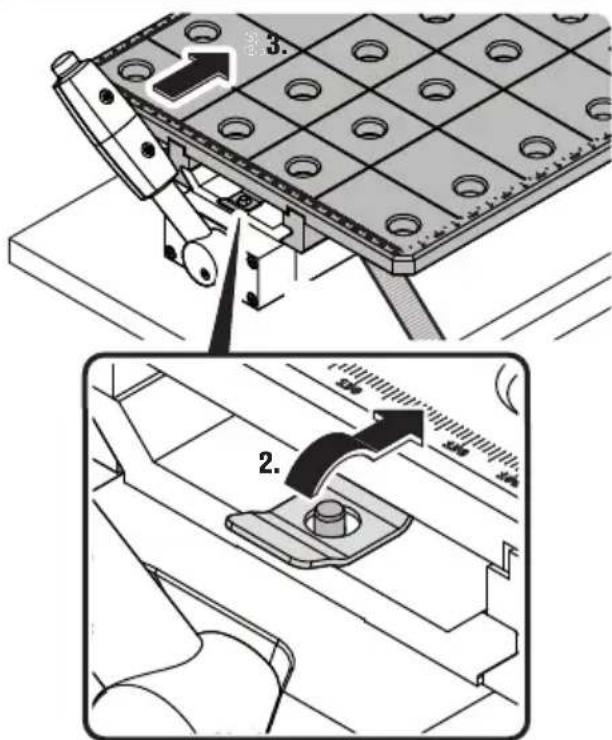
Removing the welding plate (figure 13).
Loosen the hexagon socket screws.
Push the fastening bracket up and slide the welding plate away so that the bracket goes over the fastening bolt.
Pull the welding plate off the permanent magnet.
Fig. 13
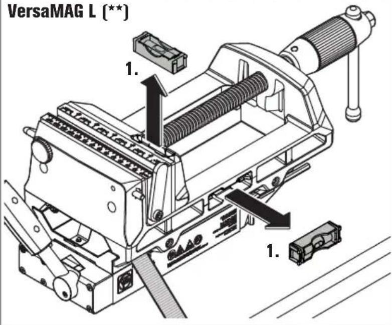
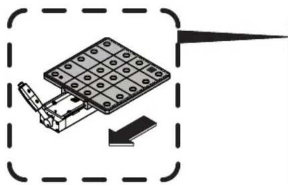
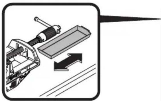
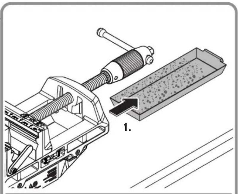
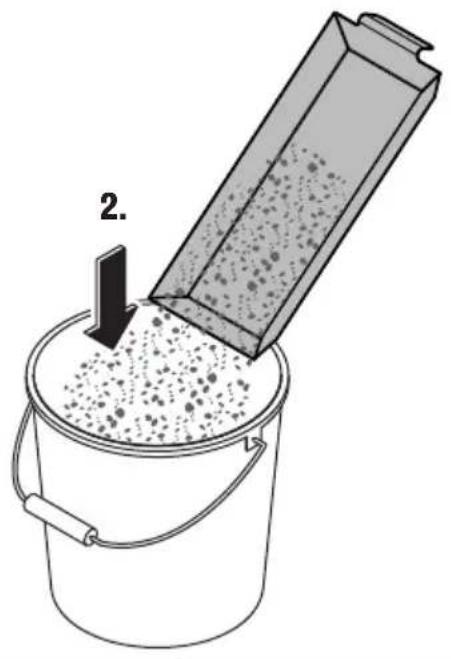
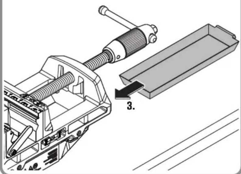
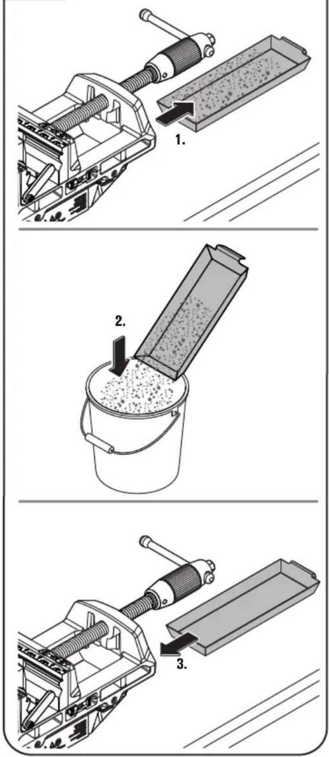
Tray (VersaMAG L [\*\*]) (figure 14).
Pull out the tray. Remove the dirt and slide the tray back in.
Fig. 14 VersaMAG L ( ^** )
Operating instructions (figure 15).
Only drill workpieces within the clamping range.
When machining workpieces, observe the maximum force that may be exerted on the workpiece outside the clamping range.
When welding, attach the ground connection directly to the workpiece or to the welding plate.
Fig. 15
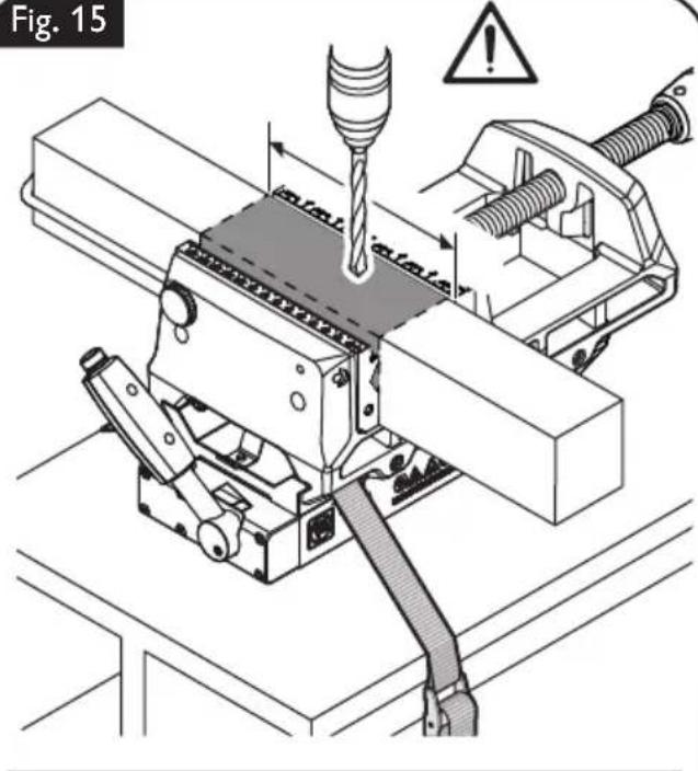
max. 1 kN
Repair and customer service.
WARNING
Before mounting or replacing cutting tool or accessories, pull the power plug.
This preventive safety measure rules out the danger of injuries through accidental starting of the power tool.
If required, you can change the following parts yourself:
- Clamping jaws, stops, tray
Service.
Renew stickers and warning indications on the product when aged and worn.
After several hours of operation, the play in the movable clamping jaw can increase. In this case, tighten the two screws on the bottom side of the movable clamping jaw so that the clamping jaw can be easily moved by hand but does not tilt.
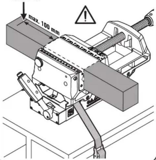
Wear detection on the magnetic foot (figure 16).
Moving the machine tool on the set-up surface causes wear to the magnetic foot. This may result in air gaps between the magnetic foot and the set-up surface and the magnetic holding power can be reduced. For checking, the magnetic foot is provided with indentations. Check for wear each time before using the machine. If one of these indentations is no longer fully visible, the magnetic foot must be replaced. Please refer to the FEIN customer service agent under www.fein.com.
WARNING
Do not remove the permanent magnets under any cir-
cumstances, as they can cause injuries and contusions or bruises.
Have your product repaired only through a qualified repair person and only using original replacement parts. This will ensure that the safety of the product is maintained.
The current spare parts list of this product can be found on the Internet under www.fein.com.
Warranty and liability.
The warranty for the product is valid in accordance with the legal regulations in the country where it is marketed. In addition, FEIN also provides a guarantee in accordance with the FEIN manufacturer's warranty declaration.
The delivery scope of your product may include only a part of the accessories described or shown in this Instruction Manual.
Environmental protection, disposal.
Packaging, worn out products and accessories should be sorted for environment-friendly recycling.
Accessories.
Only use original accessories from FEIN intended for the product. Approved accessories for the product can be found at www.fein.com.
Provided accessories (figure 17).
VersaMAG S (**)
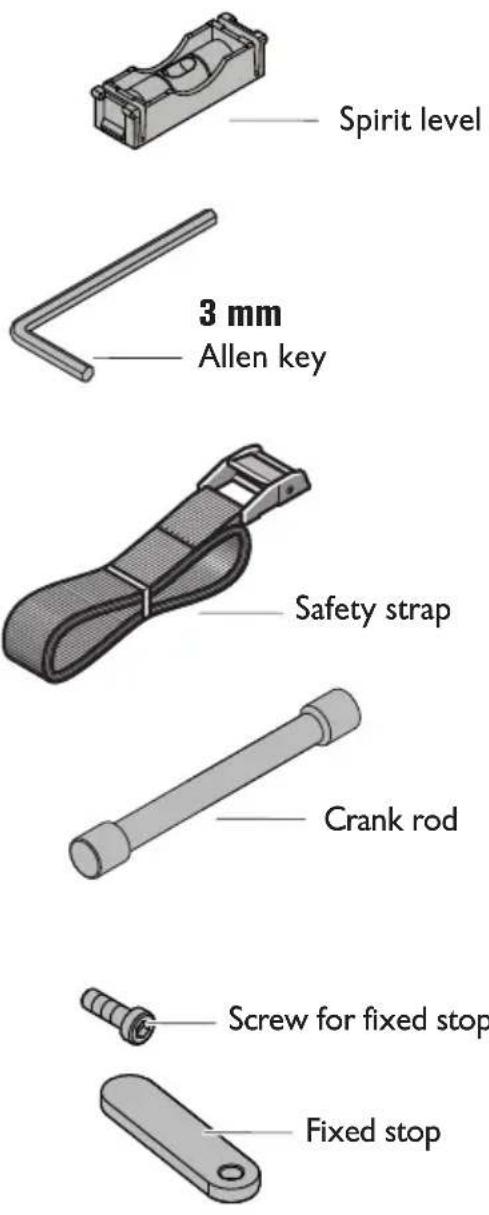
Spirit level
Allen key
Safety strap
Crank rod
Fixed stop
VersaMAG L (**)
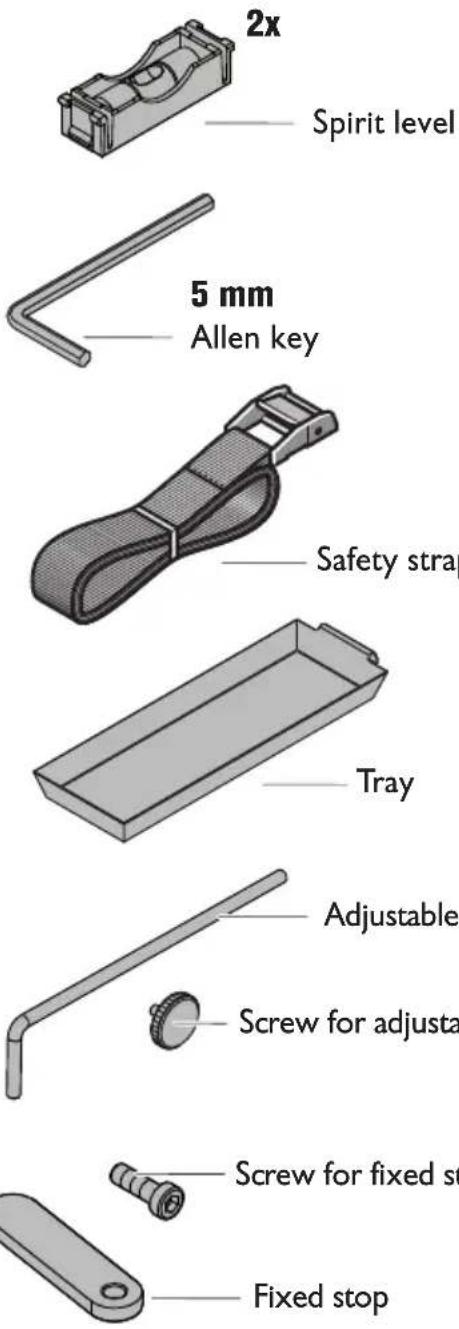
Spirit level
Allen key
Safety strap
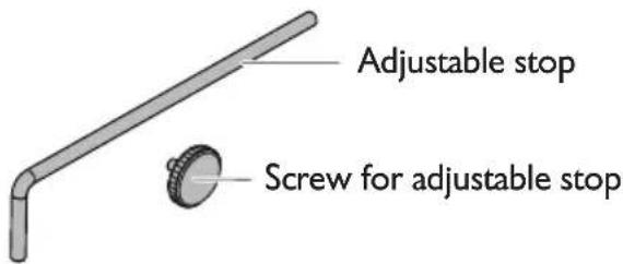
Adjustable stop
Screw for fixed stop
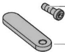
Fixed stop
Fig. 17
natural_image
Mechanical assembly diagram showing a clamping device with lever and base plate (no text or symbols)VersaMAG S (**)

VersaMAG L (**)
natural_image
Technical line drawing of a mechanical assembly with grid-patterned plate and mounting bracket (no text or symbols)
natural_image
Mechanical assembly diagram showing a clamping device with lever and base plate (no text or symbols)VersaMAG S (**)


VersaMAG L (**)

Bandeja colectora (VersaMAG L ( ^** )) (Figura 14).


- For your safety.
- WARNING
- Intended use.
- Foreseeable improper use
- Special safety instructions.
- Transport.
- Air freight
- Starting Operation.
- Operating Instructions.
- Switching the magnet on.
- Repair and customer service.
- Do not remove the permanent magnets under any circumstances, as
- Wear detection on the magnetic foot
- Warranty and liability.
- Environmental protection, disposal.
- Accessories.
- Safety instructions.
- Symbols.
- Technical description and specifications.
- Working instructions.
- For switching the magnet ON (figure 3).
- Fastening the measuring tool safety strap (figure 4).
- Switching off the magnetization (figure 5).
- Assembly instructions.
- Spirit level (figure 6).
- Fastening the vise to the permanent magnet (figure 7).
- Removing the permanent magnet from the vise (figure 8).
- Clamping a workpiece (figure 9).
- Mounting the workpiece stop (VersaMAG L [\*\*])(figure 10).
- Replacing clamping jaws (figure 11).
- Mounting the welding plate (figure 12).
- Removing the welding plate (figure 13).
- Tray (VersaMAG L [\*\*]) (figure 14).
- Operating instructions (figure 15).
- If required, you can change the following parts yourself:
- Service.
- Wear detection on the magnetic foot (figure 16).
- cumstances, as they can cause injuries and contusions or bruises.
- Provided accessories (figure 17).
- Bandeja colectora (VersaMAG L ( ** )) (Figura 14).
Brand : Fein
Model : VersaMAG
Category : Clamp