
GLM 500 Professional - Laser pointer BOSCH - Free user manual and instructions
Find the device manual for free GLM 500 Professional BOSCH in PDF.
| Product type | Laser range finder |
| Brand | Bosch |
| Model | GLM 500 Professional |
| Dimensions (L x W x H) | 106 x 45 x 24 mm |
| Weight (according to EPTA) | 0.10 kg |
| Power supply | 2 x 1.5 V LR03 (AAA) batteries |
| Battery life (alkaline batteries) | Up to approx. 100 measurements |
| Measuring range | 0.05 – 50 m (typical) |
| Measurement accuracy (typical) | ±1.5 mm |
| Laser class | 2 |
| Laser type | 635 nm, < 1 mW |
| Measuring functions | Lengths, areas, volumes, indirect height measurement, continuous measurement, addition/subtraction |
| Inclination measurement | 0° – 360° (4 x 90°), accuracy ±0.2° (typical) |
| Display | Digital display with backlight |
| Protection rating | IP54 (dust and splash water protection) |
| Operating temperature | -10 °C to +45 °C |
| Storage temperature | -20 °C to +70 °C |
| Cleaning and maintenance | Soft, damp cloth without detergents or solvents. Clean the lens like a camera lens. |
| Safety | Do not look into the laser beam. Do not point at people or animals. Use laser viewing glasses only for seeing the beam. |
| Repairability | Have repairs carried out by a qualified repairer using genuine Bosch spare parts. |
| Spare parts | Available via Bosch after-sales service (www.bosch-pt.com) |
| General information | Automatic laser shutdown after 20 s, device shutdown after 5 min. Tripod thread 1/4", memory for up to 20 values. |
Frequently Asked Questions - GLM 500 Professional BOSCH
User questions about GLM 500 Professional BOSCH
0 question about this device. Answer the ones you know or ask your own.
Ask a new question about this device
Download the instructions for your Laser pointer in PDF format for free! Find your manual GLM 500 Professional - BOSCH and take your electronic device back in hand. On this page are published all the documents necessary for the use of your device. GLM 500 Professional by BOSCH.
USER MANUAL GLM 500 Professional BOSCH
GLM 500 Professional

BOSCH
YkpaHcbKa CtopiHa 286
Ka3aK .Ber 302
Romána . . . . . . . . . . . . . . . . . . . . . . . . . . . . . . . . . . . . . . . . . . . . . . . . . . . . . . . .
MaKeDoHcN.. CtpaHua 349
Srpski Strana 364
Slovenscina Stran 379
Do not stare into beam.
Class 2 laser product
All instructions must be read and observed in order for the measuring tool to function safely. The safeguards integrated into the measuring tool may be compromised if the measuring tool is not used in accordance with these instructions. Never make warning signs on the measuring tool unrecognisable. SAVE THESE INSTRUCTIONS
FOR FUTURE REFERENCE AND INCLUDE THEM WITH THE MEASURING TOOL WHEN TRANSFERRING IT TO A THIRD PARTY.
Warning! If operating or adjustment devices other than those specified here are used or other procedures are carried out, this can lead to dangerous exposure to radiation.
The measuring tool is delivered with a warning label (marked in the illustration of the measuring tool on the graphics page with number (12)).
If the text on the warning label is not in your native language, cover it with the label supplied, which is in your language, before initial commissioning.
28|English

Do not direct the laser beam at persons or animals and do not look directly into the laser beam or at its reflection. Doing so could lead to blindless, or could cause accidents or damage to the eyes.
If laser radiation hits your eye, you must close your eyes and immediately turn your head away from the beam.
Do not make any modifications to the laser equipment.
Do not use the laser goggles as protective goggles. The laser goggles make the laser beam easier to see; they do not protect you against laser radiation.
Do not use the laser goggles as sunglasses or while driving. The laser goggles do not provide full UV protection and impair your ability to see colours.
Have the measuring tool serviced only by a qualified specialist using only original replacement parts. This will ensure that the safety of the measuring tool is maintained.
Do not let children use the laser measuring tool unsupervised. They could accidentally dazzle someone.
Do not use the measuring tool in explosive atmospheres which contain flammable liquids, gases or dust. Sparks may be produced inside the measuring tool, which can ignite dust or fumes.
Product Description and Specifications
Please unfold the fold-out page with the diagram of the measuring tool and leave it open while reading the instruction manual.
Intended Use
The measuring tool is intended for measuring distances, lengths, heights, clearances and inclines, and for calculating areas and volumes.
The measuring tool is suitable for indoor and outdoor use.
Product features
The numbering of the product features shown refers to the illustration of the measuring tool on the graphic page.
(1) Display
(2) Measuring button
(3) Plus button [+]
(4) Reference level selection button
(5) On/off button [Φ
(6) Memory button [ ]
(7) Function button [Func]
(8) Minus button [-]
(9) Battery compartment cover
(10) Locking mechanism of the battery compartment cover
(11) Serial number
(12) Laser warning label
(13) 1/4" tripod socket
(14) Reception lens
(15) Laser beam output
(16) Laser target plate
(17) Laser viewing glasses
(18) Tripod
A) Accessories shown or described are not included with the product as standard. You can find the complete selection of accessories in our accessories range.
Display elements (selection)
(a) Status bar
(b) Reference level of measurement
(c) Battery indicator
(d) Measured value lines
(e) Result line
(f) Measuring functions
(g) Display tilt angle
(h) Basic settings
Technical data
Digital laser measure GLM 500
| Article number | 3601 K72 H.. |
| Unit of measurement setting m, ft, in | |
| Measuring range (typical) 0.05–50 m | A) |
Bosch Power Tools 1 609 92A 4RG| (15.11.2018)
30 | English
| Digital laser measure GLM 500 | |
| Measuring range (typical, unfavourable conditions) 20 m | B) |
| Measuring accuracy (typical) ±1.5 mm | A) |
| Measuring accuracy (typical, unfavourable conditions) ±3.0 mm | B) |
| Smallest display unit 0.5 mm | |
| Indirect distance measurement and level | |
| Measuring range 0°-360° (4 x 90°) | |
| Inclination measurement | |
| Measuring range 0°-360° (4 x 90°) | |
| Measuring accuracy (typical) ±0.2° | C)D)E) |
| Smallest display unit 0.1° | |
| General | |
| Operating temperature -10 °C to +45 °C | F) |
| Storage temperature -20 °C to +70 °C | |
| Relative air humidity max. 90% | |
| Max. altitude 2000 m | |
| Pollution degree according to IEC 61010-1 2 | G) |
| Laser class 2 | |
| Laser type 635 nm, < 1 mW | |
| Laser beam diameter (at 25 °C) approx. | |
| - 10 m distance | 9 mm D) |
| - 50 m distance | 45 mm D) |
| Automatic switch-off after approx. | |
| - Laser | 20 s |
| - Measuring tool (without measurement) | 5 min |
| Weight according to EPTA-Procedure 01:2014 | 0.10 kg |
| Dimensions | 106 x 45 x 24 mm |
| Protection rating | IP 54 (dust and splash proof)H) |
| Batteries 2 x 1.5 V LR03 (AAA) | |
Digital laser measure GLM 500
Rechargeable batteries 2 x 1.2 V HR03 (AAA)
A) For measurements from the front edge of the measuring tool, this applies for high reflectivity of the target (e.g. a white-painted wall), weak backlighting and 25^ operating temperature. In addition, a deviation of ± 0.05mm / m must be taken into account.
B) For measurements from the rear edge of the measuring tool, applies to low reflectivity of the target (e.g. a dark-painted wall), strong backlighting and -10^ to +45^ operating temperature. In addition, a deviation of ± 0.15mm / m must be taken into account.
C) After user calibration at 0^ and 90^ ; an additional pitch error of ± 0.01^ up to 45^ (max.) must be taken into account. The left-hand side of the measuring tool serves as the reference level for inclination measurement.
D) At an operating temperature of 25^
E) The left-hand side of the measuring tool serves as the reference level for grade measurement.
F) In continuous measurement mode, the max. operating temperature is +40^ .
G) Only non-conductive deposits occur, whereby occasional temporary conductivity caused by condensation is expected.
H) Except battery compartment
The serial number (11) on the type plate is used to clearly identify your measuring tool.
Assembly
Inserting/changing the batteries
It is recommended that you use alkaline manganese batteries to operate the measuring tool.
With 1.2V batteries fewer measurements may be possible than with 1.5V batteries.
Press the locking mechanism (10) to open the battery compartment cover (9) and remove the battery compartment cover. Insert the batteries. When inserting the batteries, ensure that the polarity is correct according to the illustration on the inside of the battery compartment.
When the empty battery symbol first appears on the display, approx. 100 measurements are still possible. When the battery symbol is empty and flashes red, no further measurements are possible. Replace the batteries.
Always replace all the batteries at the same time. Only use batteries from the same manufacturer and which have the same capacity.
Take the batteries out of the measuring tool when you are not using it for a prolonged period of time. The batteries can corrode and self-discharge during prolonged storage.
32 | English
Operation
Start-Up
- Never leave the measuring tool unattended when switched on, and ensure the measuring tool is switched off after use. Others may be dazzled by the laser beam.
Protect the measuring tool from moisture and direct sunlight. - Do not expose the measuring tool to any extreme temperatures or variations in temperature. For example, do not leave it in a car for extended periods of time. In case of large variations in temperature, allow the measuring tool to adjust to the ambient temperature before putting it into operation. The precision of the measuring tool may be compromised if exposed to extreme temperatures or variations in temperature.
Avoid substantial knocks to the measuring tool and avoid dropping it. Always carry out an accuracy check before continuing work if the measuring tool has been subjected to severe external influences (see "Checking accuracy and calibrating the inclination measurement (see figures E1-E2)", page 39).
Switching on/off
- To switch on the measuring tool and the laser, briefly press the measuring button (2) [▲].
- To switch on the measuring tool without the laser, briefly press the on/off button (5) [0].
- Do not direct the laser beam at persons or animals and do not stare into the laser beam yourself (even from a distance).
To switch off the measuring tool, press and hold the on/off button (5) [].
The measured values and device settings in the memory are retained when you switch the measuring tool off.
Measuring process
Once switched on, the measuring tool is in the length measurement function. For a different measuring function, press the [Func] button (7). Use the [+] button (3) or the [-] button (8) to select the required measuring function (see "Measuring functions", page 33). Activate the measuring function with the [Func] button (7) or with the measuring button (2) [A]
Once the measuring tool has been switched on, the rear edge of the measuring tool is selected as the reference level for measurement. To change the reference level (see "Selecting the reference level (see figure A)", page 33).
Apply the measuring tool to the point at which you want to start the measurement (e.g. wall).
Note: If the measuring tool has been switched on using the on/off button (5) [0], briefly press the measuring button (2) [to switch the laser on.
To initiate the measurement, briefly press the measuring button (2) [▲] Then the laser beam is switched off. For a further measurement, repeat this process.
- Do not direct the laser beam at persons or animals and do not stare into the laser beam yourself (even from a distance).
Note: The measured value typically appears within half a second, and no later than approximately four seconds. The duration of the measurement depends on the distance, the lighting conditions and the reflective properties of the target surface. Upon completion of the measurement, the laser beam is automatically switched off.
Selecting the reference level (see figure A)
You can choose between three different reference levels for the measurement:
- The rear edge of the measuring tool (e.g. when placing against walls)
- The front edge of the measuring tool (e.g. when measuring from a table edge)
- The centre of the thread (13) (e.g. for tripod measurements)
To select the reference level, press the button (4). Use the [+] button (3) or the [-] button (8) or the button (4) to select the required reference level. The rear edge of the measuring tool is preset as the reference level every time the measuring tool is switched on.
Basic settings menu
To enter the basic settings menu (h), press and hold the [Func] button (7).
Select the respective basic setting and choose your setting.
To exit the basic settings menu, press the on/off button (5) [
Display illumination
The display illumination is continuously switched on. When no button is pressed, the display illumination is dimmed after approx. 20 seconds to preserve the batteries.
Measuring functions
Measuring length
Select the length measurement mode
To switch on the laser beam, briefly press the measuring button (2) [A]
34 | English
To measure, briefly press the measuring button (2) [4] The measured value will be shown at the bottom of the display.
Repeat the above steps for each subsequent measurement. The last measured value is at the bottom of the display, the penultimate measured value is above it, and so on.
Continuous measurement
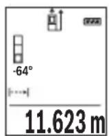
In continuous measurement mode, the measuring tool can be moved relative to the target, during which the measured value will be updated approx. every half a second. You can, for example, move a desired distance away from a wall while reading off the current distance at all times.
Select the continuous measurement mode
To switch on the laser beam, briefly press the measuring button (2) [A]
Move the measuring tool until the desired distance is shown at the bottom of the display.

Briefly pressing the measuring button (2) [will interrupt the continuous measurement. The current measured value will be shown at the bottom of the display. Pressing the measuring button (2) once more will start the continuous measurement again.
Continuous measurement automatically switches off after five minutes.
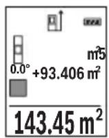
Area measurement
Select the area measurement mode
Then measure the width and length one after the other as with a length measurement.
The laser beam remains switched on between the two measurements. The distance to be measured flashes in the indicator for area measurement
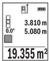
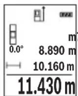
The first measured value is shown at the top of the display.
After the second measurement has been completed, the area will be automatically calculated and displayed. The end result is shown at the bottom of the display, while the individual measured values are shown above it.
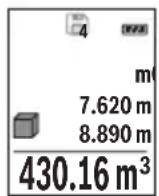
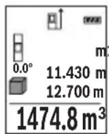
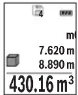
Volume measurement
Select the volume measurement mode
Then measure the width, length and depth one after the other as with a length measurement. The laser beam remains switched on between the three measurements. The distance to be measured flashes in the indicator for volume measurement
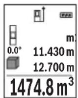
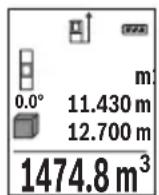
The first measured value is shown at the top of the display.
After the third measurement has been completed, the volume will be automatically calculated and displayed. The end result is shown at the bottom of the display, while the individual measured values are shown above it.
Indirect distance measurement
For indirect length measurements, three measuring modes are available. Each measuring function can be used for determining different distances.
The indirect distance measurement is used to determine distances that cannot be measured directly, due to an obstacle that would impede the path beam or the absence of a target surface that could serve as a reflector. This measuring procedure can only be employed vertically. Any horizontal deviation will lead to measurement errors.
Note: Indirect distance measurement is always less accurate than direct distance measurement. For application-related reasons, measuring errors can be greater than with direct distance measurement. To improve the accuracy of measurement, we recommend the use of a tripod (accessory).
The laser beam remains switched on between the individual measurements.
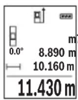
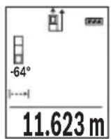
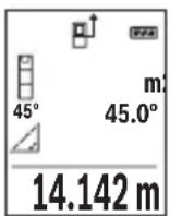
a) Indirect height measurement (see figure B)
Select the indirect height measurement mode
Ensure that the measuring tool is at the same height as the lower measuring point. Then tilt the measuring tool around the reference level and measure distance 1 as for a length measurement (displayed as a red line).
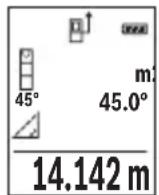
Once the measurement is complete, the result for the required distance X is displayed in the result line (e). The measured values for distance 1 and angle can be found in the measured value rows (d).
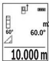
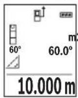
b) Double indirect height measurement (see figure C)
The measuring tool can indirectly measure all distances that lie in the vertical level of the measuring tool.
Select the double indirect height measurement mode
Measure distances 1 and 2 in succession as for a length measurement.
36 | English
Once the measurement is complete, the result for the required distance X is displayed in the result row (e). The measured values for distances 1 and 2 and angle can be found in the measured value rows (d).
Ensure that the reference level for the measurement (e.g. the rear edge of the measuring tool) remains in exactly the same place for all the individual measurements in a single measuring process.
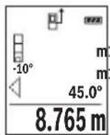
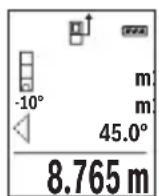
c) Indirect length measurement (see figure D)
Select the indirect length measurement mode
Ensure that the measuring tool is at the same height as the required measuring point. Then tilt the measuring tool around the reference level and measure distance 1 as for a length measurement.
Once the measurement is complete, the result for the required distance X is displayed in the result row (e). The measured values for distance 1 and angle can be found in the measured value row (d).
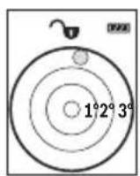
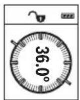
Grade measurement/digital spirit level
Select the inclination measurement/digital spirit level
The measuring tool automatically switches between two states.

The digital spirit level is used to check the horizontal or vertical alignment of an object (e.g. washing machine, refrigerator, etc.).
When the inclination exceeds 3^ , the ball in the display lights up red.
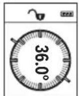
Inclination measurement is used to measure a slope or incline (e.g. of stairs, railings, when fitting furniture, laying pipes, etc.).
The left-hand side of the measuring tool serves as the reference level for inclination measurement. If the display flashes during measurement, the measuring tool has been tipped too heavily to the side.
Memory functions
The value or end result of each completed measurement is automatically saved.
Memory value display
Maximum 20 values (measured values or end results) can be retrieved.
Press the memory button (6) [ ]
The number of the memory value is shown at the top of the display, the corresponding memory value is shown at the bottom, and the corresponding measuring function is shown on the left.
Press the [+] button (3) to browse forwards through the saved values. Press the [-] button (8) to browse backwards through the saved values.
If there is no value available in the memory, 0.000 is shown at the bottom of the display and 0 at the top.
The oldest value is located in position 1 in the memory, while the newest value is in position 20 (when 20 memory values are available). When a further value is saved, it is always the oldest value in the memory that is deleted.
Deleting the memory
Press the memory button (6) [to delete the contents of the memory. Then briefly press the on/off button (5) [to delete the displayed measured value.
To delete all values in the memory, press the button (4) and the on/off button (5) [Φ] at the same time, then release the on/off button (5) [Φ].
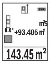
Adding/subtracting values
Measured values or end results can be added or subtracted.
Adding values
The following example describes the addition of areas:
Measure an area as described in the section on area measurement (see "Area measurement", page 34).
Press the [+] button (3). The calculated area and the ^+ symbol will be displayed.
Press the measuring button (2) [to start another area measurement. Measure the area as described in the section on area measurement (see "Area measurement", page 34). Once the second measurement is completed, the result of the second area measurement is displayed below.
To show the end result, press the measuring button (2) [ ] once more.
Note: In the case of a length measurement, the end result is displayed immediately.
To exit addition, press the [Func] button (7).
Subtracting values
To subtract values, press the button (8) [-]. The subsequent steps are the same as for the section on adding values.
38 | English
Deleting measured values
Briefly pressing the on/off button (5) [∅] will delete the last measured value in all measuring functions. Repeatedly pressing the on/off button (5) [Φ] briefly will delete the measured values in reverse order.
Changing the unit of measurement
The default unit of measurement is m (metres).
Switch on the measuring tool.
Press and hold button (7) [Func], to enter the "basic settings" menu. Select "ft/m".
Press the [+] button (3) or the [-] button (8) to change the unit of measure.
To exit the menu item, press the on/off button (5) [The selected setting remains saved after you switch off the measuring tool.
Switching sound on/off
The sound is switched on by default.
Switch on the measuring tool.
To enter the basic settings menu, press and hold the [Func] button (7). Select Press the [+] button (3) or the [-] button (8) to switch the sound on and off.
To exit the menu item, press the measuring button (2) [▲] or the on/off button (5) [Φ]. The selected setting remains saved after you switch off the measuring tool.
Practical advice
General advice
The reception lens (14) and the laser beam output (15) must not be covered during the measuring process.
The measuring tool must not be moved while a measurement is being taken. For this reason, place the measuring tool against or on a firm surface whenever possible.
Influences on the measuring range
The measuring range depends on the lighting conditions and the reflective properties of the target surface. For better visibility of the laser beam in bright extraneous light, use the laser viewing glasses (17) (accessory) and the laser target plate (16) (accessory) on shade the target area.
Influences on the measurement result
Due to physical effects, the possibility of inaccurate measurements when measuring various surfaces cannot be excluded. These include:
- Transparent surfaces (e.g. glass, water)
- Reflective surfaces (e.g. polished metal, glass)
- Porous surfaces (e.g. insulating materials)
- Structured surfaces (e.g. roughcast, natural stone).
If necessary, use the laser target plate (16) (accessory) on these surfaces.
Inaccurate measurements are also possible where the laser is pointed at target surfaces diagonally.
Layers of air at different temperatures and indirectly received reflections can also influence the measured value.
Checking accuracy and calibrating the inclination measurement (see figures E1-E2)
Regularly check the accuracy of the inclination measurement. This is accomplished by means of a reverse measurement. To do this, lay the measuring tool on a table and measure the inclination. Turn the measuring tool by 180^ and measure the inclination again. The difference between the displayed values must not exceed 0.3^ .
In case of greater deviation, the measuring tool must be recalibrated. To do so, select CAL in the settings. Follow the directions on the display.
We recommend that you perform an accuracy check and if necessary a calibration of the measuring tool after extreme temperature variations and after impact to the tool. After a temperature variation, the measuring tool must acclimatise for a while before calibration is performed.
Accuracy check of the distance measurement
You can check the accuracy of the measuring tool as follows:
-
Choose a measuring section of approx. 3 - 10m in length that is permanently unchanged, the exact length of which is known to you (e.g. room width, door opening). The measurement should be taken under favourable conditions, i.e. the measuring section should be indoors with weak backlighting and the target surface for the measurement should be smooth and reflect well.
-
Measure the section ten times in succession.
The deviation of the individual measurements from the mean value must not exceed ± 4mm over the entire measuring section in favourable conditions. Record the measurements, in order to be able to compare the accuracy later on.
Working with the tripod (accessory)
The use of a tripod is particularly necessary for larger distances. Place the measuring tool with the 1/4 thread (13) on the quick-release plate of the tripod (18) or a conventional camera tripod. Tighten it using the locking screw of the quick-release plate.
40 | English
Set the reference level for measurements with a tripod by pressing the button (4) accordingly (thread reference level).
Error message
If a measurement cannot be performed correctly, the "Error" message appears in the display. Switch the measuring tool off and back on, and start the measurement again.

The measuring tool monitors correct functioning in every measurement. If a defect is detected, the display will indicate only the symbol shown opposite and the measuring tool switches itself off. In this case, have the measuring tool checked by an after-sales service agent for Bosch power tools.
Maintenance and Servicing
Maintenance and Cleaning
Keep the measuring tool clean at all times.
Never immerse the measuring tool in water or other liquids.
Wipe off any dirt using a damp, soft cloth. Do not use any detergents or solvents.
Take particular care of the reception lens (14), which must be handled with the same level of care you would give to a pair of glasses or a camera lens.
If you discover a fault or require a repair, send the measuring tool to an authorised Bosch after-sales service agent.
After-sales service and advice on using products
Our after-sales service responds to your questions concerning maintenance and repair of your product as well as spare parts. You can find explosion drawings and information on spare parts at: www.bosch-pt.com
The Bosch product use advice team will be happy to help you with any questions about our products and their accessories.
In all correspondence and spare parts orders, please always include the 10-digit article number given on the nameplate of the product.
Great Britain
Robert Bosch Ltd. (B.S.C.)
P.O.Box 98
Broadwater Park
North Orbital Road
Denham Uxbridge
UB95HJ
At www.bosch-pt.co.uk you can order spare parts or arrange the collection of a product in need of servicing or repair.
Tel. Service: (0344) 7360109
E-Mail: boschservicecentre@bosch.com
Ireland
Origo Ltd.
Unit 23 Magna Drive
Magna Business Park
City West
Dublin 24
Tel. Service: (01) 4666700
Fax: (01) 4666888
Australia, New Zealand and Pacific Islands
Robert Bosch Australia Pty. Ltd.
Power Tools
Locked Bag 66
Clayton South VIC 3169
Customer Contact Center
Inside Australia:
Phone: (01300) 307044
Fax: (01300) 307045
Inside New Zealand:
Phone: (0800) 543353
Fax: (0800) 428570
Outside AU and NZ:
Phone: +61 395415555
www.bosch-pt.com.au
www.bosch-pt.co.nz
Republic of South Africa
Customer service
Hotline: (011) 6519600
Gauteng - BSC Service Centre
35 Roper Street, New Centre
Johannesburg
Tel.: (011) 4939375
42 | English
Fax: (011) 4930126
E-mail: bsctools@icon.co.za
KZN - BSC Service Centre
Unit E, Almar Centre
143 Crompton Street
Pinetown
Tel.: (031) 7012120
Fax: (031) 7012446
E-mail: bsc.dur@za.bosch.com
Western Cape - BSC Service Centre
Democracy Way, Prosperity Park
Milnerton
Tel.: (021) 5512577
Fax: (021) 5513223
E-mail: bsc@zsd.co.za
Bosch Headquarters
Midrand, Gauteng
Tel.: (011) 6519600
Fax: (011) 6519880
E-mail: rbsa-hq.pts@za.bosch.com
Disposal
Measuring tools, accessories and packaging should be recycled in an environmentally friendly manner.
Do not dispose of the measuring tools or rechargeable/non-rechargeable batteries with household waste.
Only for EU countries:
According to the Directive 2012/19/EU, measuring tools that are no longer usable, and according to the Directive 2006/66/EC, defective or used battery packs/batteries, must be collected separately and disposed of in an environmentally correct manner.
Français
Do not stare into beam.
Class 2 laser product
Piles rechargeables 2 × 1,2 V HR03 (AAA)
Robert Bosch (France) S.A.S.
Do not stare into beam.
Class 2 laser product
Calle Robert Bosch No. 405
C.P. 50071 Zona Industrial, Toluca - Estado de Mexico
Tel.: (52) 55 528430-62
Tel.: 800 6271286
Do not stare into beam
Class 2 laser product
Do not stare into beam
Class 2 laser product
Do not stare into beam.
Class 2 laser product
Kies de lengthemeting
Do not stare into beam.
Class 2 laser product
Bosch Service Center
Telegrafvej 3
2750 Ballerup
På www.bosch-pt.dkkan der online bestilles reservedeleller oprettes en reparations ordre.
Tlf. Service Center: 44898855
Fax: 44898755
E-Mail: vaerktoej@dk.bosch.com
Bortskaffelse
Do not stare into beam
Class 2 laser product
Bosch Service Center
Telegrafvej 3
2750 Ballerup
Danmark
Tel.: (08) 7501820 (inom Sverige)
Fax: (011) 187691
Avfallshantering
Do not stare into beam
Class 2 laser product
Lim en etikett med nordisk tekst over det engelske varselskiltet førproduktet tas i bruk forste gang.

Rett aldri laserstralen mot personer erler dyr, og se ikke selv rettinn i den direkte erler reflekterte laserstralen. Det kan före til blending, uhll og øyeskader.
150 | Norsk
Do not stare into beam
Class 2 laser product
'Opyavo metponoic (xomega metponon) 5aem
Bapoc katé EPTA-Procedure 01:2014 0,10 kg
△aotaoeic 106× 45× 24mm
Emuon pertpon anooradewv
Ttyn eumean mepon anoataeew diatieevta tpeic aeitoupyiec meponnc, nTv Bohthetaia twv onoiw mnpovv va eakpiBwOuv diaopopetike anoataoeic.
H emuon metponanooaewv xpoaiuei otnv eoipbiwn aootaoewnuou dev uopov vaetpnfouv aega eite enieh kanoio avtkeievo diaoknte tn diaapoun tnc aktivaac leizep eite enieh dev unapxei kantoia enipaveva otoyou, n onoi a xpoaiuee oav
186|EAnvika
avakaaotnpac.Autooc tpoioc metponnc mnoepi va eapapooei movo stnv katheta n kateuohvon. KaTe anoklan npoc tnv opizovtio odnyei oopaama ta metponcn.
YnobeiE: H emuon metponon tnc anootaoc elva navtoe Aiyotepo akipbcn cno tvn apeon metponon tnc anootaoc. Ta opaAmuata metpononc loyew epapouvnc miopei va elva meyautepa ano ta opaAmuata otnv aleon metponon tnc anootaoc. Tia tn beAlewn tnc akpiBecIAC TNC metpononc oac ouviotoume tn xponon evoc trinoda (eEapntma).
Avapeoa otic diapoece mepovwvec metpnoic n aktiva lezep npapaeve evepyonounevn.
Tonothe to opyavo eptponc ie to oneipwma 1/4" (13) otn baon ynpopnc aalayns
Tou pinoa (18) n evoc tpoia yia toypaqikn uxavn tou eunopiou. Biodote to staepa me tn biDa otepeownc tnc baon yphyopnc aalaync.
Do not stare into beam.
Class 2 laser produc
not stare into beam.
ss2 laser product
Robert Bosch Sp. z o.o.
not stare into beam.
Class 2 laser product
Bosch Service Center PT
KVapence 1621/16
692 01 Mikulov
Na www.bosch-pt.cz si si muzete objednat opravu Vaseho stroje nebo nahradni dily online.
Kpntepn npedeBbIX coCToHHN
-IOBpeKdEHN KOpNc N3dEINIA
Tn n nepnounduhoctb Texnueckoro o6cnyxHBaHNA
PeKOMeHdyETcOuHCTb HNCTpyMeHT OT NbIN NOCNE KaXDoI OHCNOB3OBaHH.
XpaHeHne
- Heo6xOJIMO XpaHHTb B cyXOM MecTe
-Heo6xOIMO XpaHnTb BdaIIN OT HCTOCHNKOB IOBbIeHHbIX TeMpepaTyp N BO3deiCTBna COJIHeuHbIX lyuei - npxpaHenn Heo6xoJMo H36eRaTb pe3KOro nepeana TeMnepaTyP
-eCNHnHCTpyMeHT NOCTaBnEeTcB MRAKoCymKe HnPiNtHKOBOM KeIce peKOMeHNyETcXpaHnTBnHCTpyMeHT B3ToN 3aunTHOYnakOBke - noDpo6HbIe Tpe6oBaHnK yCNoBnM XpaHeHn CMOtpnte B FOCT 15150 (YcNoBne 1)
TpaHcnoptnpoBka
- KaTeOpnueeKn He DonycKaeTcnaJeHne N IIO6bIe MexaHnueeKne BO3dIeCTBnHa yNaKOBky npu TpaHCnOPTnpOBKe
- npn pa3rpy3ke/nporpy3ke He nOnyckaTcra nCnoIb30BaHne IIO6oro BnDa TexHKn, pa8oTaIoUe no npHHuny 3aXmHa ynaKOBKn
- noDpO6HbIe Tpe6oBaHnK yCIOBnM TpaHCnOpTnpOBKn CmOTpHTe B FOCT 15150 (YcNoBHe 5)
Yka3aHnnoTexHnke 6e30nacHOCTN

Длг obecneeyнб6e3onachHиHaedexHOB pa6Otblc H3mepntelbHbIM HHCTpyMeHTOMdoJXHbI 6bITb npouHTaHbI c6bIOdaTbc8BceHHCTpyKUnn.ИспьзOBaHNe H3mepntelbHOro HHCTpyMeHTa He BCOOTBETCTBnC HaCTOaUMN yKa3aHnAMn UpeBaTO nobpexKeHHeM HHTerPpOBaHHbIX 3aunTHbIX MexaHn3MOB.HNKOrDa He N3MeHnTe
До Hey3HaBaemocTHпpeDyPpeHtBhIe Ta6nUKN Ha N3MepHTbHOM HNCTpyMeTe. XOPOIso COXPAHNTE 3TN NHCTPYKUN IN PEPEDABAIte IX BMECTEC IPEDAUEN H3MEPHTbHOr O HNCTPYMEHTA.
OctopoXH0 - npHMeHeHHe HHCtpymeHTOB dIa 06cnyxHBaHHn HnIOCTnpOBKn Hn npOeDpy Texo6cnyxHBaHH, KpOME yKa3aHHbIX 3deCb, MoKTe npNBecTH K OnachOMy BO3dEChTBHIO H3nyeHH.
270|Pycckn
H3MePHTeNbHbI HNCTpymeH TnOCTaBnaETcA C npEynpeDntelbHO Ta6nHuKo (Ha cTpaHnce C n3o6paXkeHHem H3MePHTeNbHOro HNCTpymeHTa Noka3aHa NOd HomepOM (12)).
Ecn TeKCT npedynpeHtBHO Ta6nueKn He Ha BaWem podHom 3bIke, neped nepBbIM 3anyckOM B 3KcNpyatauIO 3akneTe ee hakneKOHa BaWem podHom 3bIke, KOTOPaB BXOINT B 06bem NOCTABKN.
He hampabnIte lyu na3epa Ha IIOeH nn HKBOTbIX n cam He cmotpnte Ha npamn Hnn Otpaxaembl ny a3epa. 3TOT Lyu moKet CInNTb IIOe, CTaB npuHOn HeCuaCTHO rCyua Hnn NOBpeDnTB rna3a.
B cnyuae nonaahanna3epnro nyua B rna3 rna3a hyxho hamepeHHO 3akpbITb HemeDneHNO OTBepHyTbcr OI nuya.
He meHnTe HnueTo B naePhoM yctpoNCTBe.
He hcnonb3ynte ouKn dny pa6oTbI c na3epom B kaueCTbe 3aunTHbIX OOKOB. Oukn dny pa6oTbI c na3epom oecneuBaIo Nyuwee pacno3HaBaHne na3epHoro lyua, Ho He 3aunuAOT OT na3epHoro n3nyeHn.
He nCnoIb3yIte ouKn dIpa6OtbI c Ia3epom B kaueCTbe conHcze3aunTHbIX OYKOB Hnn 3a pyIeM. Ockn dIpa6OtbI c Ia3epom He oecneuHbAOT 3auNTy ot YΦ-uaNyuEHH N Meuaiot npabHbHOMy CBETOBOCpIraTIO.
PemOHn3MepHTeHOro HHCTpyMeHa pa3peWaeTc BbINOnHb TObKO KBaHNΦHnPoBAHHOMy NepcoHany HToBko C HCnOJb3OBAHHeM OPHnHaJIbHbIX 3aHcTeH. 3TNm ObecneuBaETc 6e30NaCHOCTb 3MepHTeHOro HHCTpyMeHTa.
He no3B0JnTe DeTAM NOb3OBAbCra Na3epHbIM H3MepHTeNbHbIM HHCTpyMeH Tom 6e3 npncmotpa. Detn MOrY T NO HeocToPOXHOCTN OcNeIHTb NOcTOPOHHIX IIO- Dei.
He pa6oTaIe C n3MePHTeJIbHbIM HnCTpyMeHToM BO B3pbIBOOnaCHO cpe, no- 6n30ctn OT rOpIOuHX XnDkoTei, ra3OB n nbInn. B n3MePHTeJIbHOM HnCTpyMeHTo MOryT o6pa3oBaTbcra NcKpbl, OT KOTOpblX MOKeT BOCIIaMeHtBcra nbInb nn npbl.
Onncahne npodukta uycnyr
Ioxaanycta,OTKpOte paKnaHHyo CtpaHnCy CnnIOCTpaunm HNCTpyMeHTa N OCTaBnIe ee OTKpbITOn, noka BbI 3yuaete pyKOBOcTBo NO 3Kcnnyatau.
PpHMeHeHne no Ha3HaueHnIO
I3MepntbHbI INHCTpyMeHT IpeHa3HaueH dIy I3MepeHn paCCTOHN, DIIIN, BbICOT, ydaJIeHn n yKIOHOB n paCteT aIooaJeN o6bEMOB.
I3mepntelbHbI INHCTpymeHT npirodeH dIra paobtbl BHyTpNI NOMEueHn Ha OTKpbITOM BO3dyxe.
H3o6paXeHHbIe coCTaBHbIe yaCTn
Hymepaun npedctabHeHHbIX COCTaBbIX yacte BblOnHeHa IIO N3obpaKeHNIO N3MepnTeNbHO IHCTpyMeHTa Ha CTpaHnce C HIIIOCTpaUmaN.
(1) DnCpIeN
(2) KhoNka n3MepeHnra [
(3)KhoNka «ПиIOc» [+]
(4) KhoNka BbIbopa nIOCKOCTn OTCuTeA
(5) BbIKHouaTeNb [
(6) KhoNka nAMrTn [
(7)Функионаьная кногka [Func]
(8)KhoNka《MnHyc》[-]
(9) Kpbiuka 6aTapeHoro oTecka
(10) ΦнкаТОр КрblшКи 6Бат apeHOrо OТсЕкa
(11) CepnHbH Homep
(12) Ppeynpeintenbna Ta6nuka na3epno I3nyueHH
(13) Pe3b6OBoe OTBepCTne nIaTnBa 1/4"
(14) PnpHmHa nnH3a
(15) BbIXoIa3epHoroLyua
(16) BnHpa Mapka dIa3epHoro lyuaA
(17) OuknДЯ pa60TbI c Ia3epHbIM INHCTpyMeHTOMA
(18) ⅢTaTnB
A) 3o6paXeHHbIe HnONnCAHbIe npHaJNeXHOCTHe BxOaT B cTaHApTHbI O6bEm NOCTABKn. POnHbI accOPTmEHT npHaJNeXHOCTeB bHaJeTe B haWe nporpaMMe npHaJNeXHOCTeI.
HdHKaTopb1(Bbl6op)
(a) Ctpoka coctoHHa
(b) IIOCKOCTb OTCuTea npH n3MepeHH
272|Pycckn
(c) INHnKAtOp 3apJKeHHoCTn 6aTaapeek
(d) 13MepeHHbte 3HaueHnA
(e) Pe3ynbTaT
(f) Peknmbi n3MepeHH
(g) HndnKaTOp yrTaHa KaHOna
(h) OCHOBHbIe HaCTpoKn
TexHnueckne daHHbIe
CTeneh3aunTbIP54(c3aunTOIOTnbl
Hn 6pbblrBoDbl)
BaTaPeN
2x1,5BLR03(AAA)
AkkymyIaTOPbIe 3JIeMeHTbl
2x1,2BHR03(AAA)
A) Iprn H3mepenHn OI nepeHnero Kpaar H3mepntelbHoro HHCTpyMeHTa,JeicTBNTelbHO Ira ceene C BbICOKo OTpaxKaTeBHo CNOC6HocTbHO (HaNP., BbIKpaWeHHa 6eNo KpaCKo CTHe), cna- 60J 3aHne NIOCBETKN pa6Oue TeMnepaTypb1 25^ .DOnONHtEBo HyKHO HCxOuNTb H3 OTKIOHnnpaKa ± 0,05MM / M
B) Ipn H3MepeHnX O T 3aHeN KpOMKn H3MepeHtBHO NHTCyMeHtA, pIn H3KO O TpaKaTeBHO CnOco6HoCTu cEn (HaNP., CTeHE, BbIKpaueHHo B TeMHbI cBeT), CNbHO IOcCBetKe n pa6OeY Tempeatype ot - 10°C do +45°C. DOnONHteBHO HyxHO hcxOJNb H3 OTKIOHeHn NOpaKa ±0,15 MM/M.
C) Nocne kaH6pOBKn IOnb3ObaTelem npn 0° n 90° HxKHO yUHTbBAbT dONOHNTbHyo nOrpeW-HocTb WaRa ± 0,01°/rpaIyc do 45° (MaKc.). B KaueCTBe IIIOCKOCTH OTCuTeTa Ira I3MepeHna YrJa NaKIOHa BbICTyNaET leBaB CTOpOHa I3MePHTeBHO IHCTpyMeHTa.
D)Пи рабочей Temперatype 25°C
E) B KaueCTBe IIOCKOCTN OTCeTa IIN HA3MepeHn yIa HAKIOHa BbICTyIaet IeBaI CTOpOHa I3MePHTeJIbHOrO IHCTpyMeHTa.
F) B pexnme npoDOnjNtEnbHoro n3MepeHHa mKc. pa6oay TeMnepaTypa coCTaBnEeT +40^
G) O6bIyH No npCytCTByET TOnbKO He npoBOJaee 3aRpa3HeHne. Ondako, KaK npaBnlo, Bo3HnKaet BpemHHa IpoBOJIMOCtB, BblBaHHa KOHeHcaJeH.
H)3aNCKJIIOUeHHEmceKUINdIaTapeek
OndHnHa HneHTnHkaun H3MePHTeBHO HOCTpyMeHTa BO3MOXHa NO cepHOMy Homepy (11) Ha 3aBOcKo Ta6nue.
C6opka
BcTabka/3ameHa 6aTapeek
B n3MePHTeNBHom HnCTpyMeHte peKOMeHnyETcH cNoHB30BaTb IeNoUHO-MapraHZeBBie 6aTapeKn nn AKKMyIaTOpHbIe 6aTapeN.
C aKKyMJIToPbIMn 6aTapeMn Ha 1,2 B Bo3MoXHO MeHbIe H3MepeHn, Yem c 6aTaPeKamn Ha 1,5 B.
UTo6bl OTkpblb KpbIbky 6batapeHoro OTeKa (9), npHXMMte cHKcaTOp (10) n CHMMte KpbIbKy 6batapeHoro OTeKa. BCTabBe 6batapeKn Hnn aKKyMnTOpHbIe 6batapeN. CnE dIte npn 3a npaBnblbHm HnPaBHeHem IIOHOCB B COOTBETCTBnC n3o6paKeHNc BByTpEHHe CTopoHbI 6batapeHoro OTeKa.
Ipn nepbOM nOBHeHH nycTOO cIMBOHa 6aTapeKn Ha dncnlee MOxHO BblONHtbe eue np6n.100 n3mpeHn. Ecn n CMBoN 6aTapeKn ncyToH mHaet KpaChbIM, daJIbHeuHne n3mepenHn HeBO3MOXHbI. 3aMeHnte 6aTapeKn Hn aKKymyIaTOPhBie 6aTapeN Bcerda 3aMeHnTe Bce 6aTapeKn/aKKymyIaTOPhBie 6aTapeN oDHOBpeMeHNo. IcnoNb3yIte TOnbKO 6aTapeKn/aKKymyIaTOPhBie 6aTapeN ODNHO pON3BOIeTEn I C ODNHa-KOBOn EMKocTbIO.
I3BLeKaIte 6aTapeH Hn AkKymyIaTOpbI H3 H3MePHTeBHOrO HHCTpyMeHTa, ecnn npoDOnXHtE hoe BpeM He 6ydeTe pa6oTaTb c Hm. Pn dInTeBHom xpa-HeHHN BO3MOxHa Kopp03n Hn camOpazraJa Ka 6aTapeek/AKKymyIaTOpHbIX 6aTapei.
Pa6ota c nHcTpymeHTOM
BkIIOueHne 3NeKToHHcTpymeHTa
He octabnayte H3MepnteHbI INHcTpymENT 6e3 npncmOTpa N BblKIOUaTe H3-MepnteHbI INHcTpymENT nOcne HcNoB3OBaHHa. Dpyrne Iua MoYT 6bITb OcIeJIeHbI Ja3eDhIM IVyOM.
3aunuante H3MePHTeBbHbI HHCTpyMeHT OT BnA rN I npMbx COJIHeuHbIX Nyuei.
He noDBepraTe H3MEpHTeBbHbI HNCTpyMeHT BO3DeIcTBHIO 3KCTpeMaIbHbIX TemnepaTpH TemnepaTyphbx nepenaoB. Hanpimep, He octabTne erO Ha dInTeBHOe BpemBaBTOMo6hJe. Pn 3HaunTeBbHX KOle6aHnx TemnpaTybI neped NaIOM HCIOB3OBAHJaTE TEMpeAtpye H3MEpHTeBHOrH NCTpyMeHTa Cta6HIN3nPOBaTcB. 3KCTpeMaIbHbIe TemnpaTybI IN TEmnpaTyphbI nepenadMoYrOTPnUaTeBHO BJIaTb HA TOUHOCTb H3MEpHTeBHO rHCTpyMeHTa.
H36eRaTe CNbHbIX ToUkOB H naEHHa N3MePHTenbHoro HHCTpyMeHTa. Pocne CNbHbIX BHeWHHX BO3DeIcTBn Ha N3MePHTeBHy INcTpyMeHT peKOMeHdyETc npOBepntb ero TouHocTb, npeXde Yem IpOdoJkaTb paBoTaTb C INcTpyMeHTom (cm. ,PiobepKa ToUHOCTn I KaIIb6pOBKa npn N3MepeHHn yHa NaKKnOHa (cm. pnc. E1-E2), CTpaHnca 282).
BkIOueHne/BbIKIOueHne
-TO6bI BKNIOHTb N3MePntBbHbI NHCTpyMeHT n Ia3ep, KOpOTKO HaxMITE Ha KHONKY N3Mepenra (2) [
- YTo6bI BKNIOuHTb N3MePnteHbHbI INHCTpyMeHT 6e3 Na3epa, KopoTko HaxMnte Ha BblKIOUaTeNb (5) [Φ.
He npabnIte na3epHbI nyu Ha IIOe Hnn XHBOTbIX n He CMOTpHTe camn B na3epHbI nyu, B TOM uCne H c 6oNbwoO paCCTOHH.
UTo6bI BBIKIOHTb H3MepNTeNbHbI INHCTpyMeHT, ydepxKNaTe BblKIOuataTeB (5) [Φ]. Prn BblKIOueHHN H3MepNTeNbHO INHCTpyMeHTa XpaHЯUneCBA NaMaTn 3HaueHHN Ha-CTPOKN INHCTpyMeHTa COxpaHЯIOTc.
PpoeUpa n3MepeHH
Iocne BkIIOUeHnI3MepHTeNbHbI INHCTpyMeHT HaxOHTCBApeKIMe I3MEpeHnIINbI.ДЯпepeKIOUeHnBdpyrOPEKIMN3MEpeHnHaxMMTe KHOKNy (7) [Func].Bbl6epHTe Heo6XoHMbI peKIM N3MEpeHn KHOKNo (3)[+] nIN KHOKNo (8)[-] (cM.,“PexMbI N3MEpeHn",CTpaHnua 276).AKTINBPuTepeKIM N3MEpeHn KHOKNo (7) [Func] nIN KHOKNo I3MEpeHn (2)[4
B kaueCTbe nIOCKOCTn OTCueta IJIa H3MepeHnI NocIe BKIIoueHnI 3aHa 3aHnI KpOMKa IHCTpyMeHTa. IJIa H3MeHEnI NIOCKOCTn OTCueta (cm. „BbIbOp IIOCKOCTn OTCueta (cm. pnc. A)" , CtpaHnua 276).
PnIOKHTe H3MePHTeHbI INHCTpyMeHT K XeJaEMO NcXoHOJ TOUKe I3MepeHHA (Hanp., K cTeHe).
Yka3aHHe: Ecnn n3MepnteBbHbI HnCTpyMeHT BkNIOueH npn NOMOuB bIKIOUaTeTg (5) [Φ, KOpOTko HaXmTE Ha KHONKy n3MpeHnra (2) []TO6bl BKNIOUHTb Na3ep.
UTo6bl npOn3BecTH n3MepeHne, KOpOTKO haxMnTe Ha KHONky n3MepeHnra (2) [AIOcne 3TOrO na3epHbI ny BbIKnOuaetc. IaJaNbHeNwero n3MepeHnnaOBTopnTe 3Ty npoceDpy.
He HanpaBnIte na3epHbI nyu Ha IIOe HnXHBOTbIX n He CMOTpHTe camn B na3epHbI nyu, B TOM uHcne H c 60nbUoro pacctOHHa.
Yka3aHHe: 06bIuHO n3MepeHHoe 3HaueHne OTo6paXaetcyepe3 0,5 c, MaKcHym Yepe3 npn6n.4 c. IpoDOnKHTeBHoCTb N3MepeHna 3aBNCIT OT paCtOHN,OCBeUeHHo
276|Pycckn
CTN OTPaXaTeBHO CNOCO6HocTH cENI. Pocne OKOHuaHn HAmepeHn Ja3epHbI Lyu ABTOMaTHueCKN OTKJIIOUaETCJ.
BbI6Op IIIOCKOCTN OTCuEta (cM. pnc. A)
PnH3MepeHHBb MoXeTe BbIbpaTb OndHy n3 Tpex NIOCKOCTe OTcyeTa:
-3aHnKpaN3MePntbHOro HcTpymeHTa (HaPnMep, npn npNKlaDbBaHnn K cTeHAM),
- npeHnKpaN3MepntbHOro NHCtpymeHTa (HaPp., npn N3MepeHHx OT KpaCtO- na),
- cepeHnHa pe3b6oBOrO OTBepCTnA (13) (HaNP.,ДЯнИЗмepeHn CO ⅢTaTINBOM)
BbI6epntepexHm HnpepbIBHO n3MepeHna
UTo6blBkHIOHTbIa3epHbI Nyu, KopoTko HaxMITE Ha KHONKy I3MepeHHa (2) [A
IpeBnraTe H3MePnteHbHbH INHCTpymeHT Do Tex nop, NOKa Bn3y INHCTpyMeHT He OTo6pa3NT Jenaemoe pacctOHaHne.
KopotkHM HaxaTHeM Ha KHONKy 3MepeHnra (2) [PexHM HenpepbIBHOrO 3MepeHnRApepbIbAeTc. Tekyuee 3MepeHHoe 3HaueHne OTO6paXaETcBHN3y Ha DCNlee. PnIOBTOpHOM HaxaTHn Ha KhoNky 3-Mepehnra (2) [OnrTB BKNIOuaeTc HEnpepbIBHOe 3MepeHne.
PexnH enpepbIBHO n3MepeHna aBtOMaTHueckn OTKJIouaETcayepe3 5MH.
H3mepenne nlouaa
Bb6epnte pexn m3mepeHn npoan
Iocne 3Toro n3MepeTe no oupeeni shnpHy n dInHy, KaK npH n3MepeHHn dInHbI. MeKdy oboHMn n3MepeHnMa3epHbI lyu ocTaetcB KJIoueHHbIM. n3MepeEmbI OTpe3OK Mnraet Ha INdkaTope n3MepeHHn Plouaadi

IepBoe H3MepeHHoe 3NaueHne OTo6paKaTaBvBepxHa DnCnJIee.
Iocne 3aBepweHn BTOPOrO H3MepeHn PLOUaDb paCCuHTbIBaetc aB- TOMaTHueckn OTo6paXaetc. KoHeuHb pe3yNbTaT OTo6paXaETc BH3y Ha DCnPlee, OTdJIbHbIe H3MepeHHbIe 3HaueHn - HAD HmM.
H3mepeHne 06bema
Bb6epnte pexn m3mpeHna o6bema
Iocne 3Toro n3MepeTe no oupeepnHny, dInHy nIy6Hy, KaK npn n3MepeHHn DnHbI. MeKdy TpeMn 3MepeHnMa3epHbI lyu octaetcBKnIOueHHbIM. n3MepeEmbI OTpe3OK Mnraet Ha INdkaTope n3MepeHnOBbema
278|Pycckn
IepBoe n3MepeHHoe 3NaueHne OTo6paXaetcB BBepy Ha nCnnee. Iocne 3aBepseHn TpeTbeRo n3MepeHn 0bem paCCuNTbIBaETcA aTOmatNueckn n OTo6paXaetc. KoHeuHb pe3yNbTaT OTo6paXaetcB Hn3y Ha nCnnee, OTdEhBhie n3MepeHHbte 3NaueHn -HaHm.
KocbeHHoe u3MepeHne pacctOHHa
ΦaKTopbI, BnHryIOuIe Ha dHaNa3OHN H3MepeHHN
Hnana3OH n3MepeHHaNCTOTOCBeUeHHOCTn HOTpaKaTeNbHO CNOC6HOCTn NOBepxHOCTn ceHN.JIpyuwe BNDIMOCHT na3epHoro Lyya npn CINbHOM NocTOPOHHem CBete ODeBaIte Na3epHbIe ouKn (17) (npHaJNeXHOCTb) INN HCNoB3yIte OTpaKaIO- yIO MNISeHb (16) (npHaJNeXHOCTb), INN 3aTeMHInTe CEneByIO NOBepxHOCTb.
ΦaKTopbI, BnHryIOuNe Ha pe3yNbTaT N3MepeHHA
I3-3aФH3Nuecknx 3ΦΦeKTOB He NCKIOUeHO, YTO npn H3MepeHH Ha pa3NHybIX NOBepxHOCTAX MOrY BO3HNKHyTb OUn6Kn H3MepeHH. K TAKIM NOBepxHOCTM OTHCATc:
- npo3paHbIe NOBepxHocTn (HaNP, CTeKIO, BOJa),
-3epKaIbHbIe NOBepxHOCTn (HaP., NOpIPOBaHHbI MeTaN, CTekNo), - nopnctbIe NOBepxHocTn (HaNP., H3OJauoHHbIe MaTepeNaJIbl)
- CtpyKtypnpoBaHHbIe NOBepXHocTn (HaNP., CtpyKtypnpoBaHHa IHTyKaTypKa, HAtypaNbHbI KAmEh).
Ipn Heo6xOJIMOCtH NcNoJIb3yIte Ha 3THX NOBepXHOCTaX Bu3nPHyIO Mapky IJIa3epHoro LyuA (16) (npHaAnJeKHOCTb).
PnKOCOM HabeHHeHN Ha cIb BO3MOXHbOwn6Kn.
Bo3dyuHbIe cnoi c pa3nHoi TempepatypoH n/nn He npraMoe OTPaKeHne TaKke MoryT OTpuatelbHO NOBnArybHa N3MepeRmoe 3HaueHne.
PpOBepKa TOnHocTn KAnN6pOBkApn H3MepeHHyrga HAKNoHa (cm. pnc. E1-E2)
Perynphno npOBepaTe ToHocb n3MepeHna HAKHOHa. 3TO OcyuceCTBnEeTcnyTEM n3MepeHn B DByx HaNPaBHeHnx (Tyda n 6paTHo). DnA 3TOrO NpOJKe Tn3MePHTbHBn HHCTpyMeHT Ha CToI n 3MepeBte yToI HAKHOHa. POBepHnte n3MepeTbeHbNn HnCTpyMeHT
Ha 180^ n CHOba n3MepbTe yroI HaKloHa. Pa3Hnca oTo6paXaemoro 3HaueHnHa npEByIiAaTb MaKc. 0,3°.
Pn60JIbIXOtKIOHeHnx Heo6xOIMO IpOBecTH HOByIO KaIb6pOBky N3MePeHTeBHO HnCTpyMeHa.ДЯ 3TOrO BbIbepTe aHactpoKax.CneDyIte yKa3aHnM Ha nCnnee.
Iocne cnIbIbIX nepenadOB Tempepatpyi N Ocne ToUKOB Mbl peKOMeHnyem npOBecTH npOBepKy TOHOCHTN INPn Heo6xOIMOCCTN pOn3BecTH KAIN6pOBky H3MepNTelbHOro HHCTpymEtA. Pn nepenadax Tempepatpyi DaIte H3MepNTelbHOMy HHCTpymEtY cTaNHN3npOBaTB CBOIO TEMpepatpy, npexde yem npON3BOIDtB erO KAIN6pOBky.
PpOBepka ToUHcTH N3MepeHHpaCCToHHN
TouHOCTb H3MePHTeJIbHOrO INHCTpyMeHTa MOxHO IPOBepITb CNeIyUoM O6pa3OM:
-BbIbepHTe He MeHJUOuNcS TeueHHeM BpeMeHn yuaCTOK dInHOK OK.3-10 M,ДINHa KOTOPOro Bam ToUHO n3BeCTHa (Happ.,UnpHa NOMEseHn,DBepHO npoeM).H3MepeHne CneDyET npoBOOnTb npn 6naorponrTHbIX ycNoBnx,T.e.yaCTOKdoJIKeH haxoDITbcB N OMEseHn CO cnaobfoHOBOI NOCBETKO IN IOBepxHOCTb ceHN DOJXHa 6blr IpaIKo H xopoSo OTpaKaTb.
-Померъту actok 10 pa3 nopond.
OTKIOHHepe3yIbTaOB OTdIbHbIX N3MepeHHN OT CpeHrO 3HaueHn He DoJXHO pRn6NaornpnTHbIX YcIOBHX IpeBbIaTb ± 4 MM Ha BCem yuaCTke. 3anpoToKoIpyTe n3-MepeHHN C TEM, UTO6bl BNOCEJeCTBm MOxHO 6blINO CpABHHTb ToHOCb.
Pa60Ta co wTaTHBOM (pHnHa,dNexKHOCTb)
Приимеоништатибocobehno Heo6xOДМОдябolyшхpacctони.пocтавынз-Mерпельнинсг themselves 1/4" (13)Ha pe3b6y wtaTnBa (18) nHn obuHoroФOTOWtATnBa.IpoUH npBnHTte HNCTpMeHT BnHTOM K pIITe WtATnBa.
YCTAHOBITE HCXOHNHYIO NIOCKOCTb (pe3b6a)ДЯ ИЗМЕРЕня CO IITABOM, HAXAВ HA KHOKNy (4).
Coo6eHne 6 oun6ke
EcnH3MepeHne BbINONHTb npaBnIbHO HeIb3a,Ha INcNIIe OTo6paXaeTc COo6ueHne 06 own6ke «Error». BbIKIOUHTe n CHOBA BKIOUHTe H3MePHTeNbHbI INCTpyMeHT, 3aTeM NaHHTe H3MepeHne 3aHOBO.

H3MepHTeBHyI HNCTpyMeHT OTCLeXHBAe IpaBnIbHOCTb pa6OtI npi KaJDom H3MepeHH. Ppi O6HapyKeHH JePeKta Ha DnCnIee OTO6paKaEaTc TOnbKO LNIb H3O6paXeHHb prdOM CmBOJ N H3MepHTeBHyI HHCTpyMeHT BbIKIOuaeTcR. B TaKOM cnyae OTnpaBBTe H3MepHTeBHyI HHCTpyMeHT B cepBnCHyIO MaTePCKyIO Bosch.
TexobnyxmbaHne n cepBnc
yI. TmHp3eBa, 65A-020
220035,r.MHHCK
TeN.: +375 (17) 254 78 71
Ten.: +375 (17) 254 79 16
a c: + 375(17)2547875
E-Mail: pt-service.by@bosch.com
050050 AnMaTbI, Ka3axCTaH
Cnyxkehna ən. nouta: service.pt.ka@bosch.com
OΦηιαnbHbB Be6-caT: www.bosch.com, www.bosch-pt.com
286|yKpaIHcbKa
Ytlln3aun
Ocnyxmbne cboi cpoK n3mepntbHbIe HHCTpyMeHTbl, npnaJnEHXoCTn yNakOBky CneNyET cdaBt Ha 3KOIOHNueCK NCHTyO peKypeauuO OTxOIOB.

He BbIbpaCbIbAaTe aKKyMnyIaTOPHbIe 6bTapeN/6bTapeNkB 6bITOBMycop!
Tonbko dna ctpaH-uehoB EC:
B COOTBETCTBnC eBPOneCKoI dHpeKTHBOI 2012/19/EU HeoNbIe H3MePntbHbIe np6op n B COOTBETCTBnC eBPOneCKoI dHpeKTHBOI 2006/66/EC HeoNbIe HnO tCnyXHBnE CBOI cPoK aKKyMylTOpHbIe 6aTapeu/6aTapeuKn DoJXHbI co6HpTaBcra pa3-DeNbHO n CdaBaTbcra Ha 3KOJOnrueckn uHCTTu peKynepaunIO.
YkpaHcbka
Bka3iBkn 3 Texhikn 6e3nekn

IpoHTaTe Bci Bka3iBKn i Dotpmyntecxix, 06 npauOBaTH 3 BmipIOBaIbHm IHCTpyMeHTo 6e3neuHO Ta HadiHo.
BnKOpHCTaHH BmipIOBaIbHO r IHcTpymeHa 6e3 dOtpMaHH uHX iHcTpkyuM oMe npN3BeCT h D0 NsIKoJKeHH iTeRpoBaHx 3axncHex Mexahi3MiB. HikOn He doBOdbTe nonepeJxBaIbHi
Ta6nuknHa BmipobbHomy IHctpymeHTi Do HeBni3HaHHocTi. IO6PE 36EPIaTE U IHCTPYKUII I NEPEDABAITE IX PA3OM 3 INPEDAUEIO BmIPOBaHBO IHCTPMEHTY.
06epexho - BHKOpncTaHHa3ac06ib 06cnyroByBaHHiaHactpoOBAHn, 1o Biip3HIObCBAID 3a3HaueHHX Bcii IHCTpyKci, a6o BHKOpncTaHHaO3BOJeHHx 3ac06ib y Heo3BolEnn Cnoci6, MoKe npH3BOdHTN Do He6e3neuHOro BnHbBy BnnpomHIOBaHH.
BHMIPIOBAHbHn IHcTpymeHT nocTauaetbca 3 nonepaJxBaIbHOIO Ta6NHcKOIO (Ha 3o6paXeHHI BHMIPIOBAhBOrO IHcTpymeHTa Ha cToPiu3 MAnIOHKOM BOHa P03NaYeHa Homepom (12)).
IEC60825-1:2014
<1mW.635nm
Laser Radiation
Do not stare into beam.
Class 2 laser product
YKso TeKCT nonepedxkyBaIbHOI Ta6nHcKN HAnHcHm He MoBOIO BaOoi KpaIHn, neped nepshm 3anyckOM B EKCnpyatauio 3akneIe II HaKneKOIO Ha MOBI BaOoi KpaIHN, 0o BXoINt b y KomnNeKT noCTauaHH.
He hnpabnIte na3epHn npomihb Ha IIOJe a6o TBapHH, i cami He DHBtbcra Ha npamn a6o BiO6paXyBaHn na3epHn npomihb. BIn MOKe 3acinHn iHnx IIOJe, cnpuHnHn Heaachi Bnpank a60 NooKoHn Oci.
Ypa3i noTppannHnna3epHoro npomeHa B OKO, HABMncHe 3aannIOuItb oui i BiDpa3y BiDBePHITbcB iD npomeHa.
Hiyorhe minyteBna3epHomypnctpoi.
He BnKOpHcTObyIe Okynapn dIpa06To 3 na3epom k3axncHi Okynapn. Okynapn dIpa06To 3 na3epom 3a6e3neuyt b Kpaue po3ni3HaBaHHra na3epHoro npomeHIO, OndHKe 3axuiaObB iD na3epHoro BnnpOMiHOBAHHa.
He BHKOPNCOTOBYIte OKyIaPn dIpa06TH 3 na3epom kK coHcE3axncHi OKyIaPn Ta He BdraTe ix, KOHN Bn 3hAxoIntecra 3a KepmOM. OkyIaPn dIpa06TH 3 na3epom He 3a6e3neuyIOb NOBHI 3axNCT BiD YΦ npOMeHIB Ta NoripuYIOb po3ni3HaBaHHa KJbOpIB.
BidaBaTe BmipIOBaIbHn IHcTpymeHT Ha pemOH Tnwe KBaIiKOBaHM 6axibzMa Ta Inwe 3 BnKOpHCTAHHm OpriHaIbHnx 3anactHH. TiIbKn 3a TaKHX yMOB BaW BmIPIOBaIbHn npnaI i Hadani 6ye 3aIIuATnc 6e3neuHm.
He do3B0nIe dIITM BHKOpHcTOByBaTH na3epHb HBMIpOBAhHbHn IHCTpyMeHT 6e3 harny. DITN MOKytb HeHaBMncHE 3acJIINrTn IHJHX IHOe.
He npaiothe 3 BnMipOBaIbHm IHCTpyMeHTOM y cepeoBnui, de icHye He6e3neka Bn6bxy BHaCNIIOK npncyTHOci rOpoux piHN, ra3IB a60 nnny. Y BnMIPOBaIbHOMy npnaDi MOkyTb yTBOPIOBaTHcI cKpn, BiJAKNX MOKe 3aImMaTHcN nn a6o napn.
IIO6 BnMKHyTN BnMipIOBaJIbHn iHCTpyMeHT, yTpIMyTe BnMKaU (5) [Φ
Y pa3i BmKHeHHB MmipIOBaIbHOrO IHCTpMeHTa 3HaueHH, 0 3HaXoJrbcB nAm'rti, I HanaStyBaHH IHCTpMeHTa 36epiraOtbcr.
Bka3ibKa: RaIO BmipHOBaHbHH iHCTpyMeHT yBIMKHeHN 3a DOonomoTOB BmHKaHa (5) [Φ, KOpOTKO HaTNCiHb Ha KHONky BmIPHOBAHHa (2) [ ]O6 yBIMKHyTN Ia3ep.
Iio6 3diinBnMipIOBaHHaHaTNCiHbHaKHONky BnMipIOBaHHa (2) [PiicnaBoIa3epHn npomihb BnMnKaCTbca. Iy npaJbWOro BnMipIOBaHHnOBTopitb zu npoueDpy.
He cnpmaOByIe na3epHn npomInb Ha IIOpei TBapHH i He dHBiTbcra y na3epHn npomInb, BkIoUaIOuHi 3 BeNkoBicTaHI.
Bka3ibKa: BmiprHe 3HaueHH 3'ABnCTbCRAK npaBnIO, npOTaROM 0,5 C, MaKCHMym uee3 np6I.4 C. TpNBanictb BmipioBaHH 3aJeKHTb BiD BiCTaHI, OCBITneHH i BiD6HBOI 3daTHOCTi cINbOBoI NOBepxHi. Iicra 3aKiHHe HBMipioBaHH Na3epHn Ipomihb ABTOMATNUHO BmNkAcTbCRA.
Bn6ip 6a30Boi nlouHHn (nVB. Man. A)
PnBmipioBaHHi Bm MoKeTe Bn6paTH OndHy 3 Tpbox 6a3OBHX PNOUH:
-3aHnKpaBmipIOBaIbHOro npnay (Hanp. pnpncTAbNHHIo CTINH),
- nepeudni KpaBnMipIOBaIbHOrO IHCTpyMeHTa (HaNP., dNBA BmMipIOBaHHB iD KpaIO cTOna),
- cepeHnHa pi3b6oBoro OTbOpy (13) (HAnp.,ДЯ BmipHOBaHb 3i 7TaTINBOM)
Bn6epitbpexHM BmipIOBaHHo6'emy
Iicna zbo rno no cepa BmipraTe u npnHy,IOBXnHy i n6nHy,Kn pni BmipioBaHHi
DobxHHn. B nepepbMix TpbOMa BmipIOBaHHMa Na3epHn IpomHb 3aJIHaCTbcA
yBIMKHyTMM. BIdpi3OK, 10 BmMipIOeTcB, 6IbMaE Ha iHdNkaTOPI BmMIPIOBaHHo6'EMy

Nephe BImipnHe 3NaueHHB iDObpaKxycbHa nCnnei 3Bepxy.
No 3aBepeHHI dpyrOTo BnMipIOBaHHo 6'Em aBTOMaTHUHO
BhpaxOByeTbcra i BiDoppaKyeTbcra. KInCeBn pe3yIbTaBiDobpaKyeTbcra
HaHcPJIe3HN3y,OKpEMi BmIPIOBaHI 3NaueHHa -HaHnM.
Henpme BmmpioBaHHBicTaHi
Henpme BnMipioBaHHB iDcTaHi MOxHa 3iINCHIOBaTH B TpbOx peKIMax BmMIPIOBaHH, BAKNX MOxHa Bn3HaATn pi3Hi BiDCTaHi.
3a donomoroHnnpamoro BmipobAHB BiCTaHI MOXHa BmipOBaTH BiCTaHI, RKi He
MOXHA BIMIPATN PIPMIM UJXOM,AKU O Ha TpaEKTopi npomeHa iche nepewkoDa a6o
Hema cIbBOoi NOBepxHi,ka 6 cnryBaIa B kOci pePneKtopa. Cei cnociB HmipOBAHn MOxHa 3actOCOBaTH IIne B BePTHKaIbHOMy HAnpMky. Byd-Ke BiXnJIeHHB TROP30HTaJIbHOMy HAnpMky pN3BOIDtB Do NOMIOK B BMIpOBaHI.
Bka3ibKa: Henpme BImipIOBaHHa BiCTaHe 3aBXn MeHs ToHc HIX npame. PoXn6Kn BImipIOBaHH MoKytb, 3BaXaOuHN Ha CneUΦiKy 3actocyBaHH, 6ytN 6IbSmmH, HIX npn PnPMOMy BImipIOBaHHi BiCTaHe. Dnla 36IbWeHH ToHocTi BImipIOBaHH Mn paHmOBVKOPNCTOByBatn WtATNB (npunad).
B napepbmi mix Okpemm BnMipIOBaHHaNna3epHn npomihb 3aIIuAeTbcyBIMKHyTNM.
a) Henpme Bmipobanha Bncotn (nB. man. B)
Bn6epitbpekHM He npMOro BmipHOBaHHa BNCOTN
Cniikkyte 3a Tm, 106 BnMipIOBaIbHn npnna3hXoDnBCHa OdHi i Ti camiBnCOTi, 10i HnxHra Toka BnMipIOBaHH. Notim Haxnltb BnMipIOBaIbHn IHCTpymENT nO BiDHOWeHHIO do 6a3oBOi IIOuHHn i BnMipRte BiDp3OK «1», Ra ce po6ntbcry pa3i BnMipIOBaHH IOBXHHN (Ha DnCnneI npedctabNeHo YepBOHOIO liHieIO).
ПисязавершениocтаньогOBIMIPIOBaHHpe3yIbTATДуkaHOrO BIDpi3Ka «X» BiO6paKaCTbcry prky pe3yIbTaTIB (e).BIMipHi 3HaueHHЯДгВiDpi3Ka «1» Ta KyTa «a» BiO6paKaIoTBcR B prdkax BIMipAHx 3HaueHb (d).
b) NodinHe Hnprme BmipIOBAAHBAHCOTN (INB. Man. C)
BmipioBaIbHn IHCTpyMeHT MOKe HENPMAO BmipIOBaTH yci BiDpi3KN, IIO 3HaxoJrTbcRy BEpTKaJIbHI pIoUHHI BmipIOBaJIbHO rIHCTpyMeHTa.
Bn6epitb pexHM noDbiHoro He npMOro BmipIOBaHHB BnCOTH
BmipraIte, kI npn BmipIOBaHHi DOBXHHN, BiPi3KN «1» i «2» B 3a3HaueHIn nocniIOBHOCTi.
Iicnla 3aBepweHHN OCTaHHbOTo BmipIOBaHHpe3yNbTaTdIyKaHO BIdpi3kaX BiO6paKaεTbcry pykny pe3yNbTaTIB (e).BmiprHi 3HaueHHn DII BIDpi3KiB 1》,2" Ta KyTa a" BiO6paKaHbCBy PraKax BmipraHNx 3HaueHb (d).
Cniikkyte 3a Tm, o6 ni d yac BCix OKpeMx BmipOBAh b a3oBa nlouHa BmipOBAHH (Hap., 3aHn KpaB BMIPOBAhoro
Pnna) 3NaOuaTouHO HA TOMy CAMOMY Micui.
c) Henpme BmipioBaHHn DOBXHHN (Hb.MaI.D)
Bn6epitb pexm Hnnpmoro BmipioBaHHaOBxHHH
296|yKpaIHcbKa
Cnikkyte 3a Tm, 06 BnMipIOBaHbHn npnaad 3haxoHBCa Ha OdHi i Ti cami BncoTi, 10i ToUKa BnMIPIOBaHHa, kY Bn BV3Haaye. NToIM haxniltB BnMIPIOBaHH n IHcTpymeHT NO BiDHOWeHHIO do 6a3OBoI IIOUHN H i BnMiprTe BiDpI3OK «1», kK ce po6ntbcra y pa3i BnMIPIOBaHHdoBXHH.
ПиялзавершениocаннбогOBIMIPIOBaHHpe3yIbTДЯуkaHOro BIDpi3ka «X» BiO6paKaAcTbcry pydky pe3ynbTaTIB(e).BIMipRHi 3HaueHHДЯ BiP3ka «1» Ta KyTa «a» BiO6paKaIoTbcraB prdkax BIMipRHNx 3HaueHb(d).
BmipioBaHH kyTIB haxnuy/uzdpobBuBatepna
Bb6epitbpexHBMipOBaHHaYbHXnuy/ncpOBOBaTePnaca BmipOBaBHn iHcTpyMeHT aBTOMaTHNo nepemKaCTbCMAIX cHmN DbOMa peKHaMaM.
Unpobn Baepnac cnrye dna nepeBipkn ropn3oHTaNbHOCTi Hn BepnkabHocTI nOxKeHH o6'kTa (HaNP.. npalbHOI MaunHH, XoOnnblhNka Toio).
Ypaazi nepeBnueHHaHXny 3^ KylbKaHa Dncnpei ropntb ueBOHm.
PexnBmipIOBaHHa Kyta Haxny CnyrE dna Bn3HaueHn nIiomy a6o haxny (hnp..cxOobnx xiHnB, npuyHn, npniPiroHci Me6nib, npn npoknaaHHI Tpy6 Toio).
Ba3OBOI pIoUHOIO IJI BmIPIOBHaHry KyTa HaxNly e IiBn KpaBmIPIOBaIbHOro IHCTpyMeHTa. JksoB IIpoueci BmIPIOBaHHaMraeIHdNKaTOp, To ce O3Haayc, 10 BmIPIOBaIbHn npnaD 3aHaTTo CInbHo
Haxilenei B6ik.
Функцnam'nti
3haueHHa60pe3yIbTaT KOxHOrO OKpemOro BmIpIOBaHH 36epiraεTbcR B nam'rti ABTomATnUHO.
BidobpaXeHH36epExeHx 3NaueHb
BnKlnkaTm MoXHa He 6iNbwe 20 3HaueHb (BnMipRnX 3HaueHb a6o KInCeBnx peZyIbTaIb).
HaTnCHiB KHNkY nAm'rTi (6) [
3Bepxy Ha dncnnei BiO6paKyecbC HOMep KOMipKn nam'rti, 3Hn3y - BiNobIDhe 36epxeHe 3NaueHHa, a 3niBa - BiNOBIDHN pexHM BmIPIOBAHH.
HaTnckaIte KhoNky (3) [+] , ilo6 npokpyyBaTu 36epxeHi 3NaueHnBnepei.
HaTnCKaTe KHOHkky (8)[-], 106 npokpyyBaTH 36epexeHi 3haueHHA
Ha3a.
Якwo ynam'anti Hemae 3haueHb, 3n3y Ha dincnei BiO6paKaetbcra «0.000», a 3Bepxy - «0».
Haicapiwe 3haeHHra 3haxoHTbcra y naM'ATi Homep 1, haHOBiue - Homep 20 (aKIO e 20 36epexeHHx 3haeHb). Prn 36epexeHHi HOBOrO 3haeHHra 3aBXdN BIDaJIeTbcra Haicapiwe 3haeHHra.
CThpahnBmicty nam'atI
Дя Oушения 3mICTy Nam'ЯTi HaTnCHiB Ha KhoNky Nam'ЯTi (6) [Пnotim KopoТКо HaTnCHiB Ha BmNKaY (5) [Ф,иб ВидалNTи BiDobpaЖуBaHe 3haUeHЯ.
Uo6 BndaHNTuYci 3HaueHHra, 0cMiCTaBcB NaM'rTi, OHOaCHO HaTNCHTb KHOKky (4)i BHMNKaay (5) [Φ, a NOTIM BiPyctITb BMHKaay (5) []
DoaBaHHB/BiHimaHH3HaueHb
BmipnHaueHHa 60 KIncEbi pe3yIbTaTm MoKHa DoaBaTH a6o BiHimatN.
DdaBaan3aueHb
YnactynHompynknlaIIOaETbc8OnncD0daBaHHnIOou:
Bn3haTe nIoUy 3riIHO 3 po3iIOM «BmipIOBaHHaII"» (INB. „BmipIOBaHHaII"”,CTopIHka 294).
HaTnchItb KhONky (3) [+]. BiO6paKaIoTBcNippaXoBaHa nloua i CnMB0l «+».
HaHCHiItb Ha KhoNky BmipIOBaHHa (2) [A,06 po3noaTHHOBe BmipIOBaHHnlooi. Bn3haute nlouy 3riDHO 3 po3dINOM «BmipIOBaHHnlooi» (DNB. „BmipIOBaHHnlooi", CtopiHKa 294). Odpa3y no 3aBepeHHi DpyrOBO BmipIOBaHHpe3ynbTaT pyrOro
BHMipOBaHHI NIOU BiO6paXaETbC B HNXHII YAcTHHi DnCnner. IINB iDopaxeHHKInCeBOrO pe3yNbTaTy Ue pa3 HaTNCiB KHONKy BmIPoBaHHr (2) [A
Bka3iBaKa:Ypa3i BmMipIOBaHHI OOBKNHpe3ynbTaT BiO6paKaεTbcσOpa3y.
Lio6 BnInTn 3 pexmMy dOdaBaHHa, HATNCHITb Ha KONky (7) [Func].
298|yKpaIHcbKa
Bidhimannha 3NaueHb
Iio6 BnKoHaTn BiHimHaHHaHaueHb, HATNCHTb KHOKNy (8) [-]. IOpaJIbwi iii aHaNoIurHi po3diny «IopaBaHHaHaueHb».
CTupaHnBvMipaHnx 3HaueHb
KopoTKM HaTnCKaHHa HbMMKaay (5) [B ycix peXmMax BmipOBAHH MoxHa BdaHTN octaHHe OTpMaHe BmIPoBaHe 3HaueHH. KIbKapa3OBm KopoTKM HaTnCKaHHa HbMMKaay (5) [OKpeMi BmipRHi 3HaueHH BdaJIOTbcr y 3BOPOTHI INocIIOBHOCTi.
3mHaOHHnCiBnMipIOBaHHa
Y6a3OBHX HanaU TyBaHHx OINHnueo BmipIOBaHHB BCTaHOBneHn (M) (MeTp). YbIMKHTb BmipIOBaJIbHn IHCTpyMeHT.
YtpmyTe KhoNky (7) [Func], 06 noTpanNTB MeHIO «Ba3OBI hanaWtByBaHHa. O6epiTB «ΦyT/M».
HaTnCHITb Ha KhoNky (3) [+] a6o Ha KhoNky (8) [-], 06 3miHHTn OOnHnO BmIPIOBaHH.
Ioo6 3aHnHTN nyHKMeHIO,HaTNCiTB Ha BHMKau (5)[P. Iicna BHMKHeHHB HmipioBaHOro iHcTpymeHTy obahe HanaHTyBaHHa 3aHnuaacTbcra 36epexEHM.
YbIMKHeHHBumKHeHHa 3Byky
y6a3OBHX HanaHTyBaHHx 3Byk yBimKHeHn.
YbIMKHTb BmipIOBaIbHn iHCTpymeHT.
Utpmyte KhoNky (7) [Func], 06 notpanHTB MeHIO «Ba3OBI HanaStyBaHHa. Bn6epitb. HaTncHtB Ha KhoNky (3) [+] a6oHa KhoNky (8)[-], 06 yBIMKHytn a6o BHMKHytN 3Byk.
山063aHnHTNpyHKT MeHIO,HaTNCiHb Ha KHONky BmMipOBAHHa (2)[4a6oHa BmNKaU (5) [Φ. PicJy BmKHeHHBmIPOAbhHO IHCTpMyeHTy o6paHe HanaHTyBaHHa 3aHnAeTbca 36epExeHM.
Bka3iBkn 0do p6oTH
3araanbHi Bka3iBKN
IprnHmHa IIn3a (14) imcue BnxOdy Ia3epHoro npomeH (15) nIac BmipOBaHH noBHHi 6yTH BiKpNTi.
ΦaKTopn BnHbBy Ha diana3OH BmipIOBaHHa
Padiyc BmipobHn 3aJenb BiD OCBiTneHH i BiD6NBHOI 3aTHOCTi cInbOBOIO NOBepxHi.
Uo6 na3epHn npomih b 6yNo Kpaue BnHO npn CnBHom 3OBHIshbOMy OCBIteHHi,
BraTe na3epHni Oknyapn (17) (npnaad) i BkOpncTOBy Te Bi3npy Mapky (16) (npnaad) a60 3aTinHtbcNbOBy nobepxHIO.
ΦaKtopn BnNBy Ha pe3ynbTaT BmipioBaHHA
3BaKaIOUH Na φi3NHy eΦeKTH, He MoXHa BKNLHOHTN NOMUNK Bpe3yNbTaTAX BmIPIOBAHH npn BmIPIOBAHHx Ha pI3Hnx NOBepxHx. CIoN BiDHOCTbCa:
- npo3opi noBepxhi (Happ, cKIO, BODa),
- NOBepxHi, 10 BiD3epKaIIOHb (HaNP., NpIpOBAHm MetaI, CKNo),
- nopncti nobepxhi (hanp., i3oJauiHi MaTepiann)
- ctpyKtpyoBaHi noBepxHi (Hanp., ctpyKtpyoBaHa wTyKaTypka, npnpOHi 6ydiBeBnKamHb).
3a noTpe6n BVKOpncToBvIe Ha TaKHX NOBepXHx Bi3Npy HmApKy (16) (npHaJ).
PnKOComyHaBeeHHiHaZilbMOJINBIOMNIKN.
Kpim Toro,Ha pe3ynbTaT BmipioBaHH MoKyb BnNBAuN 7apn nobitpr 3 pi3HO TeMnepaTypo1 a60 He npame BiD3epKaIIOBaHH.
Ipebeipka toHocri ta kani6pyBaHHa nla BmipIOBaHHa KyTa Haxnny (nB. man.E1-E2)
Perynepno nepebiprnte tohictb Bmipobahnkyta haxny. Lc 3niCHIOCTbca IJnxOM BmipobahnraB O6ox Haprmkax. IyI cyboRo noknaiTb BmipobabHn npnaHa CTIN Ta BmiprTe Kyt haxny. Nopephitb BmipobabHn iHCTpyMeHT Ha 180^ Ta 3HOBy BmipraTe Kyt haxny. Pi3nua BiO6paKyaBaHOro 3haueHHn He NobHHa nepe6ilb7uBaTH mAcC. 0,3°.
Pn 6iNbB WENKHX BIXHNHeHHx Ntpi6HO 3HOBy BiKaJIbpyBaTHn BMIpOBAHn npnaI. Iy cboR Bn6epitb HanaWtBuHaHx.BkOHaTe Bka3iBKn Ha nCnnei.
Iicna Cnblhnx TemnepaTyPhNX KOINBaHb i NOWTOBXiB MN paNMO nepeBipHTN TOHlCTb i 3diChNTn 3a Heo6xidHcTIO kani6pyBaHHra BmIPIOBaIbHO r IHcTpymeHTy. Iicna 3miHn TemnepaTyPi daTe BmIPIOBaIbHOMy IHcTpymeHTy CTaBiI3yBaTHCBOIO TemnepaTypy, nepw HIX 3diCHIOBaTN KANI6pyBaHHra.
Ipebipka ToHocTi BmipobHHB iDtaHi
TouHicTB BmipIOBaIbHOro iHCTpyMeHTy MOxHa nepeBipITu TAKHM YUHOM:
-Bn6epiB iIraHky doBXHHIO np6bn.3-10M,po3mip kOi He mHaTbcra I ToHO Bam BiDomn (Hanp., shnpHa npmiueHHa, DBePHn npopis). BmIpioBaHHa Ma 3diCHIOBAtncs 3a cnpnATnBHX yMOB,TO6To dIJIHkMae 3hAxoHTbcra B npMIuEHHI
300|yKpaIHcbKa
3i cna6kHM fHOOBHm NiDCBiyBaHHm i ciNbOBA NOBepxHa BnMipIOBaHHMa 6bytn PiBHOIO I do6pe BiD3epKaIIOBaTH.
- PpomipTe dInaHky 10 pa3iB nocnilb.
BidxnneHHaOKpemHx 3HaueHb BmipIOBaHb BiCepeHbOro 3HaueHnra 3a CnpnAeHHX yMOB He NOBHNO nepeBuSyBaTH ± 4 MM Ha Bci DInHci. 3anpoTOKoHoiTe BmipIOBaHH, Uo6 y Ma6yThbOMy MoxHa 6yNo NopIBHTn ToHICTb.
Po6ota 3i wTaTHBOM (npnnaD)
IHTB OO6HbHO Heo6xIDHn npn po6otax Ha BENKc BiDCTaHI. NocTaBTe BmipIOBaIbHn IHCTpyMeNT rHizOM nI d IITb1/4" (13)Ha pI3b6y IITbBA (18) a60 3BnuAHHOro FOToUHTaHbA. PnIKpyITb Horo fIKCyUChm TBHtOM Ha IWBnKD03MHHi IINaCTHHi.
3aaiTe BiinobiHy 6a3OBy nIoUHHy dIy BmipIOBaHHra 3I uTATNBOM HaTnCKaHHaM Ha KhoNky (4) (6a3OBA nIoUHHa: pi3b6a).
Pobidomlenn npo nomnilkn
YKIO BIKOHaTHBIMIPUBAHN IpaBnIbHO HEMOXKNBO,HaDcNnei BiOpBXeTBCNIOJOMNeHHIPO NOMILKY «Error».BIMKHITb I3HOBY BBIMKHITb BIMIPUBaHnIHCTpymENT,NOTIM NOHITb BIMIPUBAHN HaHOBO.

BmipobalbHn IHctpmeHT BiDctexy npaBnblhictbpo60tn npn KoxHomBy BmipobahHi. Ipn BnBHeHHi HeNoaKn Ha DncPnei BiObpaKytbcra NlWe CnMBoI, 10 cToiTb Nopyu, i BmipobalbHn IHctpmeHT BmNkaTbcra. YCbOMy BnPaKy nepaate CBi BmipobalbHn pnilad uepe3 MaarHn B cepBichy MaNCTepHIO Bosch.
Texhuihe 06cnyroByBaHHaicepBic
Texhuihe 06cnyrobybaHH i ouHueHH
3aBXKn TpImaTe BmipIOBaHn npnaB YnCTOTi.
He 3aHypioTe BnMipIOBaIbHn npnaI y BOy a6o iHsi piHN.
BHTnpaTe 3a6pydHeHH BONOrOIO M'koIO raHcIPKOIO. He BNKOpNCToByte KODHNX MNIOUHX 3ac06IB a6o p03uHHNKIB.
Oco6nbo o6epexHo dOrnaTe 3a npHOMHOIO liH3oIO (14), Hehae 3a OKyIpaMn abo liH3oIO foToanapata.
Y pa3i DepeKty a60 dIy peMOHTy BiInpaBte BHMipIOBaIbHn IHCTpyMeHT do ABTOH3OBAHOI cepBicHOI MaIcTePHi Bosch.
Cepbic i koncynbtaqii 3 nHTaHb 3actocyBaHHA
B cepbicihi maictepHi Bn otprmaTe BiinobiHa BaWi 3aHHTAHNCTOCOBHO pemOnTy i texhuiHoro o6cIyroBvBaHHra BaWOrO npOdyKty. ManIOHNk B DeTAnx i HOpMaCiIO uOdo 3anuactNH MoKHa 3HaHTn 3a aDpecoIo: www.bosch-pt.com
Komahda cnibpo6itHnkiB Bosch 3 hanaHHa KOncylbTaui 0do BnKOpncTahnn npodykii i3 zaoBolneHHm BiIOBictb Ha Baui 3anHTAHn CTOCOBHO hawoi npodykui Ta npnaadn do Hei.
Pn BCixdoaTkoBnx 3aHHTAHHx Ta 3aMOBneHHi 3aHuaCTH, bYdb NaCKa, 3a3HaayTe 10-3NaUHm HOpE dIg 3aMOBNeHHy, 1O cTOITb Ha nacnpTHi Ta6nUcpi npodykTy.
IapaHTiHe 06cnyroByBaHHa I pEmoHT eNeKtpoiHCTpyMeHTy 3diChIOJbCBAIDIOBIDHO DO BnMOr I HOpM BnROTOBIIOBaHa Ha TepHTopii BCix KpaIH Nlue y fipMOBnx a6o ABTopn3OBAHNCEpbICHNX CEHTpax fipMN «PObert BoW». PONEPENXEHH!
BnKOpNCTaHHKaOHtpaΦakTHoi npOdykui Hebe3neueH Bekcnnyatau i MoKe MaTH HeratNBHI hAcniDkn dIra 3dopOB'Y. BnroTOBHeHH i p03NoBcOJxehnn KaHTpaΦakTHoi
npodykii nepeceiIyetybca 3a 3akoHOM B aadmiHictpaTHBHomY i KpHmHaJIbHOMy npraKy.
YkpaHa
BOWCepBicHmLcHTpeKToHCTpyMeHTiB
Byn.KpaHn1
02660 KniB 60
OpaIaHaHydAnCOHimTa3aayYcblbIaBl.
CaKtay
KpyfKaKJepde caKTay KepeK
- KOFapbI TeMnpaTypa Ke3iHeH KHe KYH CaylenepiH acepiHeH anbc CaTay KepeK
- caKtay Ke3iHne TemnepaTypaHbIH KeHeT aybITKybIHah KOpFay KepeK
-erep Kypan JyMcaK cemKe Hemece PnactNK KeiCTe XeTKi3iNce OHbl OcbI 03iH Koprafbii Ka6bHa caTay YcBhlnaDbI
- caTay wapTapbl TypaIbI KocbIMwa aKnapaT any ywiH MEMCT 15150 (Lapt 1) KyKaTbIH KapaHbI3
TacbImanay
TacbMaIay KeiHne OHIMdi KyaNaTyFa JkHe Ke3 KeJrE H MExaHKnBik BIKnAe TpyKe KaTaH, TblbIM CaIbHaDbl
-6ocaty/xyktey Ke3iHne nakeTTi KbicaTBi MaunHaIapDbI NaJaIaHyf pyKcat 6epinmei.
-TacbImaJday wapTtapbl TaanTapbH MEMCT 15150 (5 wapt) KxKaTbH OkBihB3.
Kayinci3ik HycKaynapbl

Onwey Kypanbimen Kayinci3 Xehe ceHmdi Jxmbic ictey yuin Hapnbik HyckaynbikTapdbI OKbin opbIHday KepeK. Onwey KypanbIH ocbl HycKaynapra cai naDanaH6ay onwey KypanbIHdafbi KipictipinreH Kayinci3dk wapanapbHa JxfabIMcbI3 acep etedi. Onwey KypanbIHdaFBlecekpTynepi KeipIN6eHTIH KbIMMaHbI3.OCbl
HYCKAYIAPBICAKTAN,ONLIUYKYPALIBH BACKAIAPFA BEPHEOIAIAPBIOKOCA YCbIHbIHbl3.
A6aB 60nbHb3 -erep ocbI Jepde 6epinren naDanaHy Hemece Ty3ety KypandaPbIHAN 6acka KypanDaH naDanaHaC Hemece 6acka Kymbc ědicTepi opbIHAnca 6yn Kaynti caynere wabHyfa anbl Kenyi MymkIn.
Onuwe KypalbI eckepTy TaKTacbImen 6ipre XeTki3inReH (onwey KypaBbHbIn CypTeIHne rpaФнka 6etIHde (12) HemipimEn 6enrInehren).
IEC60825-1:2014
<1mW.635nm
Laser Radiation
Do not stare into beam
Class 2 laser product
Erep eckepty xancbipmacbi ci3iH eniH3 tiine 60nmaca, anfawkbi naanahyaan anbIH OHbIH opbHa ci3iH eniH3 tiinHe 60nfAnxancbipMaHbI Xa6bictpblbl3.

Ja3ep caynciH aam Hemece Kahyapnapra 6aftTamaHb3 XHe 03iH3 de tikeen Hemece wafbnfah na3ep caynciH kapaMaHb3. OcbinaaMdpBn K03IH WafblDpybIMyMKIN, CTCi3 OKFaIapra anbin Kenyi XHe Ke3di 3aKbIMdaybl MYMKIN.
Erepnaep cayneci Ke3re Tycce Ke3eepdi Xymbin 6actbI caynepeH apbl KapaTy kepeK.
Na3ep KypbInfbcbiHda eWkaHdae3repty opbHdaMaHbI3.
▶ Μa3ep Képy Ke3inDipirin KoprAhnBsiu Ke3inDipiri petiHne naJdaan6aHbI. Na3ep Képy Ke3inDipirin Na3ep cayncin JkaKcbipak Képy yui H KbImet KacainbI, bipak on Na3ep cayncineH Kopfamaibl.
Na3ep Kepy Ke3inDipirih KYN Ke3inDipiri petiHne Hemece Kon Ko3raIbcIHn naaHaHa6aHb13. Na3ep Kepi Ke3inDipiri yIbtpafoNeT caynepeiHeh TOnbIK Kopram peH Kepy KaBneTih a3aHTabI.
Θnwey kypabIn Tek 6iikTi mAmHa fXhe apHaynbI 6eKeKTepeMeH XeHdTeH3. Con apkblbI eNwey kypan Kayinci3diirH caKaTaeCb13.
Bananap na3ep enwey kypanbH 6aKbInaycbl3 naDanaH6acbH. Onap 6inme aamdapdbH Ke3IH wafblbICTbpy MymkiH.
XaHaTbIH cyMbIKtBikTap,ra3dap HeMece wah XnbINFaH xkapbInbc Kayni 6ap opta anwey Kypabih naDanaH6aHbI3. OJwey Kypanbl yKbH WbIFapbIn, WAnDbI XaHdbIpBn, oPT TyDbipyMymKiH.
Ohim xhe kyat cnaTamaCbl
OJwey KpaanbHbIH CypTe 6ap 6eTI aUbIn, naJaIaHy HcKayNbIFbIH OKy Ke3iHne OHbl aUbIK YCTaHbI3.
MaKcaTbI 6oBbIHua KOnDaHy
OJwey KypaIbI KaIbIKTbIKTapdbI, Y3blHdbIKTapdbI, 6NikTKePdi, apaIbIKTapdbI, KneBeyepdi eJweyre JHe aydAn Meh aymakTapdbI ecenTeyre apHaIraH. OJwey KypaIbI iKi Meh cbiptkbl aMakTapda naJaIaNHyfa apHaIFaH.
KopcetinreH KypamdbI 6eKeTep
KepcetinreH KypamdaTap Hemipi cypeTep 6ap 6eTteri eIwey KypaBbHbH cnnaTTaMaCbHa KaTbICTbl.
(1) DnCpIeN
(2) Θηιωey TγιMeci [ ]
(3)ПлiocТуМeci[+]
(4) Heri3ri Ka3bIKTbIKTbTaHday TyMecci
(5) Kocy-ewipy Tymeci [
(6) CaKtay TyIMeci [
(7)Функцу Тунмeci [Func]
(8)MnHycTynMeci[-]
(9) BaTaper 6eNIMi KaKNaFbI
(10) BaTape 6eIimi KaKnaFbHbH KyNnbl
(11) CepnIbIK HEmip
(12) Na3ep eckepTy TaKTacbl
(13) 1/4 IOIMIK WtTaTHB 6ypaHdacbl
(14) Ka6blnday nH3acbl
(15) Na3ep cayneciHH WbIfbcbl
(16) Na3ep HbIcAHdbIK TaKTacBIA
(17) Na3ep Kepy Ke3iDipiriA
(18) ⅢTaNtB
A) BeHeneHReH Hemece CnnaTtAnFaH Xa6DbIKTap CTaNapTTbXeTKi3y KJEmMeH KAMtbINMaIbI. ToBik Xa6DbIKTapdbI 6i3iH Xa6DbIKTap 6arapNaMamB13aH Ta6acbI3.
Kepcetkiu 3nemHTeP (TaHaMaIbI)
(a) Kyi naheji
(b)
(c) BaTapeHnDnKaTOpbl
(d) Θηιών ΚεπεΜερί όκολαβό
(e) Hətnxkepep konaafbl
(f) Θnwey dyHKunapbl
(g) EHC6ypbblbHkepcTeKl
(h) Heri3ri npametpnp
TexHnKaIbIK mJImeTtep
-10M KaWbIKTbIKTa 9MM
-50MkaWbIKTbIKTa45MM
Uipy aBtOMaTnKacbl WamMeH TEmeHJeIeH COH
CaMaFbI EPTA-Procedure 01:2014 cai
KoIeMep
KopfaHbIc Tpyi
Batapeanap
0,10K
106×45×24MM
IP54(waHMeHwaBpaHdbCydaH KopraFaH)
2x1,5BLR03(AAA)
CaHdbik naep kaawbIKtbk eJlweriwi GLM 500
AkkymyIaTOPbIK3JIeMeHTTep 2x1,2BHR03(AAA)
A) Θηληωγκραβλθινιδηναλιβίναβχπειηην Θηληωετην, Hbɪcaɪhaɪhɪŋxσορáβɪwɪaβɪnɪbɪcɪy ἀρεχεci (Mbɪcaɪbɪ, aʌk Tycηηθ δόσηfah Kæbɪpfa), επις Φɔнɒdɪk JæpɑbɪkTaɪhɪbɪpɪy xəHe 25°C xμmɪbɪc Temηpepatypacbɪ yʊɪn Kɔŋdaɪhɪbɪnʌbɪ. Kocbɪmɪs ± 0,05 MM/ m aybɪTkʊdɪbɪ ecenke any kepek.
B) Θηωeγ KypaIbHbI apTKbI KbIpHaH ΘηωeReHne HbIcHaJa WafblbcIy MymKlHiI rI JxOFapbl 60nca (MbIcAbl, KOHbIP 6oIFaH Ka6bipfa), φθΟΙΚ XαρβιK TbIK KaTbI 60nII, XyMbIC TemNepaTypacbl -10°C xəHe +45°C apaIbIfbHda 60nybl TnIC. KocbIMua ±0,15 MM/M ayblKydb ecenke any Kepek.
C) NaIaHaHbI O° XHe 90° apaIbIFbIHda KaIb6pIeHHeH KeiH; ± 0,01° KocbIMwa KeTepiy ayIbTKybIH / eH Kebi 45° dApexKeHi (MaKc.) eckey KaKeT. EJIcTI eJIwey YwIH HerI3ri Jka3bIKtbIK petIHne eJIwey KpaIbIHbIH cOJ KaFbl naJaHaHbIJaBbl.
D) 25^ Kymblc TemnepaTypacbHa
E) Ehicti enwey yuih anbiktaamabik xaa3bIKpeHne enwey kypaibihc con Xaftnai daanbblndbl.
F) Y3dikci3 onuwey peKmHne MaKc. Kymbc TeMnpepaTpaCb+40°C KypaHdbI.
G) Tek KaHa ToK eTKi36eHIn nac naIda 6oIaIbI, 6ipak Kei6ip JkaFdIapDa epy HtNkeciHde ToE eTKi3y Kabineti naIda 6oNyI KyTIneJI.
H) 6aTapee 6eimieHeh Tbc
OJyKpyaHbIH 3aybITbIK TaKaTaNacbHdafbI cepnNbIK Hemip (11) OHbl Dypbc aHbIKTaYFa KEMeKTecdi.
Mоntаждан
Batapeaapdbicany/annactbipy
Ouey Kypaib yuih ankaiHH maprahec 6ataperecbH Hemece aKKymyTOpbH naDanaHy cblhlndbl.
1,2 BɔŋbTTbɪk aKKyMnyTOpMeH 1,5 BɔŋbTTbɪk 6aTapeɪnapfca nblcTbɪpfraHaKeMipeK eɪneuŋepdi opbɪHdəy MymkiH.
BaTape 6eimih KAKnafbH (9) auy yuih bICbipMaHbI (10) 6acbln, KaKNaKTbI aWbIHb3. BaTapeHbI Hemece aKKyMylrTopdbI caIbHbI3. BaTape 6eimih iwiHderi cypetTe KepcetirreHne nnIOCTapdbH dypbic opHaNACbyH KaMTaMacbI etIH3.
Erep6oc 6batape 6enrici andbin dncnne de anfaw pet nada 6onca, wam. 100 enwey apekeTIN opbHdayfa 6oanaB. Erep 6batape 6enrici 6oc 6oIbn, Kb3bn TycTe kHaCa, OHda eWbip oIwemdepdi opbHdayfa 6oImaIbI. Batape Hemece akKymyIaTopnapdbI aIIMactblpblIbI3.
Bapbik 6batapeanap Hemece akymyIaTOpnapdbi 6ipde anMaCTbipbHb3. Tek 6ip eHipuyinH kHe KyatbI 6ipde 6batapeanap Hemece akymyIaTOpnapdbi naJanaHbIHb3.
Θηωeу KypaIbIи y3ak yaKbIT naДanaH6acaHbI3, 6atapeaIapdbI HeMece aKKymIaTOpIaPdbI Θηωeу KypaIbIHah WbIFapBIn anbIbI3. Y3ak yaKbIT JkaTkaH 6atapeaIap HeMece aKKymIaTOpIaP TO T bacybI JxHe 3apAdbI XoFAITybl MyMkiH.
Пайдалану
Icke Kocy
KocynbI 3apraTay KypanbIH 6aKbInaycbl3 KaNdbIpMaHbI 3 XHe eHwe KypanbIH naDanahydAn coH eWipiH. Na3ep cayneCimeH aamdaPbIH Ke3IH WafblbcTbipy MymkiH.
Onuey KypanbH cb3dah XkHe TikeNe KyH caynepeHcakTaHbI3.
Θnwey KypaNbHa aHpbKwa TempepaTypa Hemece TempepaTypa Tep6enynepi acep etneyi Tnic. OHbMbicaBbABTOKeJIkTe y3ak yaKbIT KaIdbipMaHbI3. Ynkeh TempepaTypa bIK aybIKyapbl JkaFdaBbIHda aIbIMeH eNlwey KypaNbIHbIH TempepaTacbH dYpbIC naIdanaHbIHbI3. AHPbKwa TempepaTypa Hemece TempepaTypa Tep6enynepi KezIHne OJwey KypaNbIHbIH daIir TeMeHdEnyi MymkiH.
Θnwey KypaBbH KaTbI cofbinydAn Hemece Tycydeh CaKaTbI3. Θnwey KypaBbHa cbiptkb KaTbI acep etinreHHen KeiH eLwey KypaBbHbH JxMbICbH JxanFactbpydAn 6ypbH aPdA bIM dAnik TeKcepiciH opbHdaH3 (KapaHb3 ,dAnikTi TeKcepuy xHe enic oIweydi KaNbepney (E1-E2 cypeTepiH kapaHbI3), Bef 315).
Kocy/ewipy
- Θιηwey KypaJIbI MeH Na3epdi icKe Kocy ywiH Θιηwey TyMeciH (2) [▲] Kbicka Mep3imDi 6acblb3.
- Θιηών κύραβήν έλερείσει icodeκόγ γιδην κόγου εωίργ τυμέπει (5) [Φ] Κύικας Μερείπει δάβηνι.
- Πa3ep caynecin adamapra hemece xahyapnapra 6arbittamaHBi3 xhe Tinti anbictan 6oncbH xapbik caynecine 03iH3 kapaMaHbi3.
Oney KypanbH ewipy ywiH Kocy-ewipy TyMeciH (5) [6acBn TpyBHB3.
OIIwey KypaBIn OwiipReHde JkaTAtypFaH MAnep MeH KypbIINfblnapaMeTpnepi caKaTaIaNbl.
Olnwey aici
KockaHHan KeiH onwey Kypalb y3bIHdbk onwey fynKcncsbHa TpaBb. Baca onwey fynKcncbHa aybcy wih (7) [Func] tyMecin bacbHb3. Kanaybl eJwey fynKcncbH (3) [+ ] HeMece (8) [-] tyMeci apKbInb (kapaHb3,Onwey
Функцилары",Бet 310)Тармавиан.Tандань.ошey ФункциrcbH (7)[Func] Tymecimeh Hemece oIwey Tymecimeh (2)[4icke KocbHbI3.
OnlweydiH Heri3ri Jka3bIKTbIFb KocyaH COH OIwey KypaNbIHbIH apTKbl Kbipbl TaHdaIaBl. Heri3ri Jka3bIKTbIKTb ayibcTbipy ywiH (KapaHbI3 „Heri3ri Jka3bIKTbIKTb TaHday (A cypeTiH kapaHbI3), Bet 309).
OJwey KpaBnH eJweydi KaKetti bactankiHyKTecine (Mbicn, Ka6bipfa) KOJIbHb3.
Hyckay: erep eunwey Kypanbikoccy-ewipy TyMecinH (5) [Φ] KemerimekcbiHaH 6onca, naepdi kocy ywiH enwey TyMecin (2) [Kbicka Mep3imDi 6acblb3.
OJIweydi 6ocaty ywiH eIwey TyMeciH (2) [Kbicka Mep3imDi 6acbHb3. CocBn Ia3ep cayneci owei. Backa enwey ywiH ocbl aicti kaHTanaHb3.
- Пазер саунecин садамдра Неме са hyapnapfa 6afbTTamaHbI3 xhe tinti anbictah bocbIH JapbIK caynecihe 3iH3 KapamahbI3.
Hyckay: onwey mahi aete 0,5 cek neh eh y3aftbwaamameh 4 cek ihiHne KepceTinei.
Onwey y3aKtftb KaWbIKtBkTAH, XapbIKTBk KaFdaNBI MeH HbICAHdbIK aMaKTbIH KaTapy
KacneTepiHe bainahbcIb. Onweydi aAKTaFAHHaH COH na3ep cayneci ABTomATbI peTte
ewedi.
Heri3ri xa3bIKtbIKtbI TaHday (A cypeTIN KapaHbI3)
OJwey yuhiy u typi Heri3ri Ka3bIKTBkTapdbH apacbiHaTaHday MyMKiH:
-0nwey KypaBbHbH apTkbl Xneri (MbicaIb, Ka6bipFa oPhaNaCTbIPraHda),
-0nIwey KypalbHbIH aIbIHfbl Kneri (MbicaJIb, YCTeJXneriHeH eIWeereHde),
-6ypaHdaHbIH(13) opTaCbI (MbicaIbl, WtTaTbneH eJWeReHde)
(4) TyMeciH Heri3ri Jka3bIKbIKbI TaHay yuH 6acbHbI. Kaaynl Heri3ri Jka3bIKbIKbI
(3) [+] HeMece (8) [- HeMece (4) TyMeci apKbIbTaHdaHb3. OJWey KpaIbIHbH,ap6ip KocblbHa TaJWey KpaIbIHbH apTKbl KbIbI Heri3ri Jka3bIKTBk petiHde anDbIHah peTtenre 6oana.
"Heri3ri napametpnp" m3ipi
"Heri3ri napametnpep" (h) M3ipine kipy ywiH (7) [Func] Tymecin 6acbI IN TypbHbI3. Heri3ri napametpmen 03IH3 napametpiH3di TaHaHbI3.
"Heri3ri napametnpep" m3ipineH wbyy ywiH kocy-ooipy tymecin (5) [6acbHb3.
Диспей карын.
Iincnne JapbfbH y3ak yaKbITka KocBInfah. Nephe 6acblmaca Iincnne JapbfbI am. cekyHntan coh 20 6atapeHb/akKymJrTopdbI yHemdey ywiH kapaHfbIHaHabiI.
OIIwey cyHKcuaapbl
¥3biHdbikTbIeWey
¥3bHdbKtbI ΘJIwey-dyHKUACbIH TaHaHbI3.
Naep caynein Kocy yuih eonwey tymein (2) [Kbicka Meprimdi 6acblb3.
OJIwey yuiH eJwey Tymecin (2) [Kbicka Mep3imdi bacbHb3. OJwey mHi TeMeHne dncnneKepcetinei.
XofapbdaftkepcetinrenKaamdapdbepKeHHri OJwe yuih KaTalaH3.CoHfB eJwe MAnDiNcPiNeiH TeMeHrI XaFbIHda TypaDbI, COHfbHbH aNbIHDaftbe OJwey MHi Xofapbcihda TypaDbI T.6.
Y3dkci3 enuey
Y3nikci3 enweye enwey KypabHn HbicaHa XbIxxbITyfa 60anaB, OHda enwey KeNemi
waM. ap 0,5 cekynd caBHn KaHapadbl. Mbicanbl, Ka6bpFaDaH Kepekti KaWbIKTBkKa
eTyIH3 MymkiH, KaWbIKTbIKTbApdaHbIM Kepyre 60anaBl.
Y3diKci3 enweydiHaHdaHbI3.
Ja3ep cayneiH Kocy ywiH eIwey TyMeciH (2) [Kbicka Mep3imDi 6acblb3.
OJwey KypanbH KepeKti KaWbIKTBiK DnCnneH iH TEmeHri 6enirHde KepceTinreHwe XblXblTbHb3.
Y3dkci3 oIweydi aayTay ywiH oIwey TyMecin (2) [Kbicka Mep3imDi 6acblb3. AfbIMdbk oIwey mHi TeMeHne dncnneJe Kepcetinei. OIwey TyMecin (2) [KaTaNbckaHa y3dkci3 oIwey kaTata icKe Kocblndbl.
Y3dkci3 eIwey 5 MmHyTTaH KeiH aBTOMaTbI Type eWeedi.
Ayaanbl eonwey
AydahdbIeJHwey HHKUcBtHaTaHaHb3.
Cohan coh eH MeH y3bIHdbfBih dAneKti TypDe y3bIHdbIKTbi enWeReHde enWeHi3. Eki enwey apacbHa na3ep cayneci kocynbl 60bn KaIaN. OJWeHetIH KaWbIKTBk aydaHdbI eNwey HnDKaTOPbIHd XbINbIKTaIdbI.

AnfaKbI OJwey MHi DnCnne JxOFapbCbIHda KOpceTinei. Ekinwi OJweydi aKaTafHHaH CoN ayDn aBTOMaTTbI ecENTeIN KOpceTinei. CoFbI HAtNXe DnCnne TEmHri XaFbIHda KOpceTinei, an 6OneK OJwey MaHdepi JxOFapbCbIHda.
Koenni enwey
KoIeM OJIweydi TaHdaHbI3.
Cohn eHIN, y3bIHdbfBH xHe TepeHdiRiH dneKTI Tpye y3bIHdbIKtbl eIweHdeE nWeH3. Yw eIwey apacbIHda na3ep caynci kocynbl 60bnk kanaDb. OIweHetin KaBbIKTBK KJIeMdi EJWEY HNDKATOpbIHda XbINbIKTaHbl.
Anfawkbl eIwey mHI dncnne JxofapbicbHda Kepcetinei.
YwiHsi enweydi aKtafahHHan coN Kelemi ABTomattb ecentenin
Kepcetinei. CoHfb HATNXe dncnne TeMeHri XaFbIHda Kepcetinei, an
6eneK eIwey mAndepj xofapbicbHda.
KaHama KaWbIKTbIKbit Onwey
KaHama KaIbIKTbIKTbI eIwey ywiH yw eIwey cyHKcnaCbI 6ap, onap apKblbI Tpyni KaIbIKTbIKTapDbI eIwey MymKiH.
KaHama KaWbIKTBkTbI eNlwey cayne KOnbIHda Keepri Typyb Hemece HbICaHdbK aMak KaTapaTbH Jep petiHde Konxetimdi 6oImaybi ce6eBiHeh Tikeen eNlleH6eTIN KaWbIKTBkTapDbI eNlweyre Kb3MeT eTei. OcbI eNwey adicih TEk TIK bafta naDalaHy MymkiH. KcndeHeH 6aftaFb ayltky eNlwey kateiiktepihe anbln kecenei.
Hyckay: KaHaMa KaBbIKTbIKTbI OJWeyHdAnDiI aPdAim TiKeNe KaBbIKTbIKTbI eJWeyDen TEmeHipeK bOJaBl. NaDanaHy KaFdaNbHa 6aNaHbICTbI peTe oJWey KaTeiRi TiKeNe KaBbIKTbIKTbI OJWey KATEiRiHeN yKHeN bOJaBl. OJWey dAnDiRi H KaKcapTy ySiH TaFaHbl NaDanaHyDbI YCbHAmbl3 (Ka6DbIKTap).
Oe npapacbHda naep cayneci kocynbl 6oBn Kanadbl.
a)KaHama 6nIKtikTeIeUey (B cypeTin KapaHbI3)
XaHaMa 6nIKtIKTioIwey dyHKUcBbIH TaHaHbI3.
Onwey KypaibHbIH ToMeHri Onwey HkyTecimH bip 6niKTke 6onybHa Ke3 XeTKi3H3.
Onwey KypaibH Heri3rI Xa3bIKTBkTaH KaibpBn, KaWbIKTBkTb1 "1" Y3bIHDbIKTbI
enweReHdE onWeHiz (DncnneJe Kbl3bIn cb3bIK peTINHe).
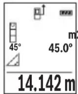
OJIwey aAKTaNfAHHaH KeiH KaKeTTI "X" KaUbIKtBIFbIH OJIwey HAnxkeCi HAnxKeIep JOnaFbIHDa (e) KOpCetineDi. "1" KaUbIKtBIFbIMeH "a" 6ypbIbIHbIH, OJIwey MAnHepi OJIwey MAnHepiH (d) XoJaFbIHda TpaIbI.
b) Koc kahama 6niktikti oIwey (C cypetih kappaHb13)
OJwey KpyaBb OHbH BepTKKaIbI DeHReiHDe XaTaTbIH 6apNbIK KaWbIKTBkTapDbI XaHaMa eJweyi MyMkiH.
Koc kahama 6niktiKti eJnwey cyHKuiaCbH TaHaHbI3.
Y3bIHbIKTbI eHJereHdEe "1"KaHe "2"KaWBikTBkTapbIH ocbl peTTinik BoBHwa eHJI3.
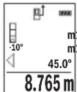
OJIwey aAKTaNfAHHaH KeiH KaKeTTI "X" KaUbIKMbIFbIH OJWey HAnxkeCi HAnxKeIep JOnaFbIHda (e) Kepcetinei. "1", "2" KaUbIKMbITapbl MeH "a" 6pybUbIHbIH oJWey MAnHepi OJWey MAnHepiHiD (d) XoJaFbIHDa TpaIbI.
OJIweyHIn Heri3ri Jka3bIKtblfbl (MbICanbl, OJWey KypaIbIHbIN apTKbl Xneri) bapIbIK eJwey apeKeTepinderiJe eJwey aicinHe 6ip JaaJa
bonaDbI.
c)KaHama y3bIHdbIKTbI eNwey (D cypeTih kapaHbi3)
KaHaMa y3bHbIKbI eNlwey HKUNcBtH TaHaHbI3.
OJnwey KypaibHbH, i3JeIReH eJWey HkyTeCimEn 6ip 6niKtKe 6onybHa Ke3 JeTki3iH3.
CodaH KeiH eJwey KpaIbIH Heri3ri Ka3bIKtbIKTaH KaIbIPbIN, "1" KaIbIKtbIFbIH Y3bIHdbIKtB eJWereHne enWeH3.
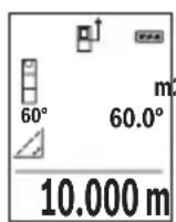
OJIwey aIaTaNfAHHaH KeiH KaKeTTi "X" KaUbIKtBIFbIH OJIwey HATNXeCi HAtNXeIep JOnaFbIHda (e) KOpCetineDi. "1" KaUbIKtBIFbIMeH "a" 6ypbluHbIH eJWey MAnpei oJWey MAnepiHi (d) JOnaFbIHda TpaIbl.
Enicti enwey/cahdik dehrre
Ehicti eJwey/caHbIK DeHReI cyHKunrCbIH TaHaHb3.
Olnwey kypaibeki KyapacbHda 3repte.i.
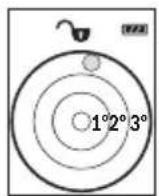
CaHbIK DeHRe HbICaHHbIH Ropn3OHTaIbI HeMeCe BepTKKaIbI
6aFbITAnybiHa Kbl3MeT eTei (MbICaJIbI, Kip JyFbIIMaUNHa, cyblTkBII
XHe T.6.).
Erep 3^ eHicTeHa cbln KeTc, nCnneIe KblbIn TycI waJxHaNbbl.
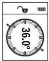
KoIbeyi eIwey KeTePiNtI HeMece hicTi (MbIcAlbl, CAtbl, TaHbIITapbl, XnHa3dApbl Kipictipyde, Ky6blpnapbl canydaT.6.) OIweYRe KbI3MeT eteJI.
Ehici Tey yin Heri3ri Xa3bIKtbK petiHne 0we KypalbHbHcON XaFbl naDanaHbIaNb. Owe npocciH, bapbcIHda Hndkatop XbIbnkTaca, 0we Kypalb6yipineH KaTbKncainTbnfah 6oIaNbl.
CaKtayfynKcunnapbl
OpOpbHdAnFaH EJIeUdiH MHi MeH COHfbl HAtNXeCi aBTOMaTTb CaKaTaNAbI.
CaKtanaFaH mH KepcetKiWi
MaKcHMaJIbI 20 mHdi (eHwey mHepi Hemece coHfbI HHTHXepe) WAKbIpy MymKiH. CaKtay TyMeciH (6) [6acblb3.
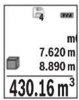
DncnneinHxofapfblXafblHa caKtaTaNFAH mHdiH Hmipi KepcTeinei, an TeMeHne Tnicti caKtaTaNFAH mH beH conda Tnicti eHwe yHKuncbI. CaKtaTaNFAH mHepdi anfa etki3y ywiH (3) [+] TYMecih bacbiH3. CaKtaTaNFAH mHepdi apTKa etki3y ywiH (8) [-] TYMecih bacbiH3. KaTaMaH xok bOnca, dncnneinH ToMeHri XafblHa "0,000", an Xofapfbl XafblHa "0" KepcTeinei.
Eh eckimH Jaa1- no3nna, an eh coHfbm 20-no3nna Tpaab (20 kad mHi konkeimdi bocca).Keinri mHdi caKtaFaHaJkaTt aepdaBIM e h ecki mH KObIaBbl.
JaTbI eipy
Xa iuiHdericiH XOIO YsiH CaTay TYMeciH (6) [6acbIb3. CoaH KeiH KOpCetinre H MAni XOIO YsiH Kocy-ooipy TYMeciH (5) [Kbicka Mep3imdi bacihbi3.
XaTa 6ap 6apbik MAnepdi KIOU yuH (4) TYMeci MeH KOCy-ewipy TYMecin (5) [6] 6ip yaKbTTa 6acBn, codan Kein Kocy-ewipy TYMecin (5) [6xibepiH3.
Mэндерді кocу/any
OJIeuy MaHepi Hemece CoHfBi HAtnKepepi Kocy Hemece any MyMkiH.
Māndeρdi Kocy
TemeHderiMbicaaydaHaapdbikocycnnataFaH:
Ka3bIKTBkTb "Ka3bIKTBkTb eJnwey" (KapaHb3 ,AydaHdb eJnwey", Bc 310) 6enimi 6oynihwa ecenTehi3.
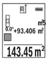
(3) [+] Tnymecin 6acbHb3. EcenTeIreH aydaH MeH " ^+ " 6enrici Kepcetinei.
OJwey tyMecin (2) [6acbIn, keiHri aydaHdbI eJwey apeKeTih 6actaHb3. Ka3bIKtbIKtbi "Ka3bIKtbIKtbi eJwey" (kapaHb3 „Aydadbl eJwey", Bet 310) 6oImi 6oBbHwa aHbIKtaHb3. EkiHwi eJwey opbHdAnfahHaH coH, ekHsi aydaH eJweydiH hAtnxKeci dncnneiH
TeMeHri KaFbIHda Kepcetinei. CoHfBI HAtnxHei Kepcety ywiH eIwey TyMecih (2) [KaTt6acblh3.
Hycay: y3bIHbIKtbl 0JIwey ke3iHde coHfbl HaTHnKe depey Kepcetinei. Kocyaan sbIfy wih (7) [Func] Tymecin bacHBi3.
Məndepdi any
Məndepni any ywiH (8) [-] TYmecin 6acbIb3. KeiHi apeKeTTep "MaHdep Kocy" Ādi ciHe yKcac.
Oltwey Hataxkepein koo
Kocy-ewipy TyMecin (5) [Фкьіcka Мерзimdi bacy apkblb bapnbk eIwey Функіларында coHfbl ecntenreH eIwey mAnH xOIOFA boIaIb. Kocy-ewipy TyMeci (5) [Фбірпше pet Кьіcka Мерзimdi bacbInraHaДа eIwey mHdepi kepi peTINik БоиьИша коьылады.
OIIeM 6ipnirin aybictbipy
Her3iri peTtey "m" (MeTp) eIwem 6ipniri 60bn ta6binaDbl.
Oney KypaJIbIH KocBHyI3.
"Heri3ri napameTpnep" m3ipine Kipy ywiH (7) [Func] Tymecin 6acbIn TypbHbI3. "ft/m" TaHaHbI3.
(3) [+] Hemece (8) [-] TyImeciH 6acbH, eIiueM 6ipJIirH aybIcTbIpbHb3.
M3ip TapMaFbIHah 乌f fy yuH Kocy-ewipy TymeciH (5) [6acbIbI. OJwey KypaJIH eiprehHeH KeiH TaHaIraH npaMeTp caKaTaIaIbI.
IbIbIcTbIKocy/ewipy
Heri3ri napametpe De bI6bc Kocynb.
Onwey KypaJIbIH KOcBiHbI3.
"Heri3ri napameTpnep" m3ipine Kipy ysiH (7) [Func] Tymecin 6acbln TypbHbI3. TaHaHbI3. (3) [+] Hemece (8) [-] Tymecin 6acbln, Dbl6bICTbl Kocbln eWipiH3.
Məsip Tapmafbihah shby yshin oIwe tyMeciH (2) [Ahemce Kocy-ewipy TymeciH (5) [6acbbl3. OJwe kypaBH eWipreHHe KeiH taHaanFaH npaMeTp caKaTanaBbl.
Painanany Hycaynapbi
KannbHcyckaynbikTap
Ka6blnday nH3acbl (14) MeH na3ep cayneciHH sbIfbcBn (15) eHwey ke3iHde Ka6byfa 6oImaIbI.
OJIwey Kpyanbl eIweyeKe K03fanybIMymKIn emec. CoI ywiH eIwey KypaBnH TypaKtbl Tipek aHa KOHyBhl3.
Onwey aMaFbHa ocepnep
Ouwey aMaFbI XapBkTbIK XaFdaNbI MeH HbICaHdbIK aMaKTBIH KaTapy KaCneTTepiHe 6aIIaHbICTbI. KaTbI 6eIe XapBkTA na3ep cayneci JkaKcbI KepHy i YwiH na3ep Kepy Ke3inDipirih (17) (KepeK-kaPak) XaHE na3ep HbICaHdbIK TaKTacBH (16) (KepeK-kaPak) NaIdanaHbIN, MaKCaTbI Xa3blkTbIK Tbi OwipiH3.
"RepMec" 50, 7 ka6aT
Te.n.: +7 (727) 331 31 00
c: + 7 (727) 2330787
E-Mail: ptka@bosch.com
CepBnCTIK Kbl3MeT KepcTeTy opTaIbIKTapbl MeH Ka6blDay nyHKTePiHi MeKeH-XaBl TypaIbI TOnblK XeHe e3eKti aKnapaTbI Ci3: www.bosch-professional.kz pecMn caTTaH ana aIacbl3
Kədere xapaty
OJIwey KypaIbIH, OHbIH Xa6DbIKTapbi MeH KaNTaMaCbIH KOpShaFaH opTaHbI KOpFaHTbIH Kdere Jkapaty OphbHa TancbIpy KaKeT.
OJnuey KypaIapbH JkHe aKKymIaTOpIaPbI/6aTapeIaPbI yKOKbICbHa TactamaHbI3!
318 Romana
Tek KaHa EO enepi ywiH:
Eypona 2012/19/EU epexeci boynbHwa japaMcb3 eIwey KypaIapbl Jxhe Eypona 2006/66/EC epexeci boynbHwa 3akbIMdaIFaH HeMece ecki aKKymyIaTOp/batapeJnap 6eKek KHNbIn KaDepe JapaTbIybi KaKeT.
Româna
Instruţiuni de siguranta

Service scule electrice
Strada Horia Macelariu Nr. 30-34, sector 1
013937 Bucuresti
Yka3aHn8 3a cnryphnoct

3a da pa6oHTe c n3MepBaTeHnH ypeD 6e3oNaCHO n cnrypHo, Tp6Ba da npOteTe H cna3BaTe BcHKn Yka3aHH. Ako n3MepBaTeHNrT ypeD He 6bDe n3non3BaH Cbo6pa3HO HactoJUHTe Yka3aHH, BrpaJeHtE B Hero 3aunTHm MexAHn3Mn Morat Da 6bDat YBpeDeHH. Hnkora He ocTabraIte npedynpHeNTHnTe Ta6eKN no n3MepBa-
TeHHypeI da 6bdaT HeueTnBn. CbXPAHRAIe TPRXJIHBO TE3N YKA3AHN I rI PPeIABAITE 3AEIDHO C N3MEPBATEHINrYPEI.
BHHMaHHe - aKo ce n3non3BaT dpyr, pa3nHn OT noCooHnte tyk cbopbXeHH 3a ynpabIeHne Hn KaIIb6pHpaHne Hn Ce n3BbPWBat dpyr npoceDpyn, TOBa Mo- Xe da DoBepe do onacHO n3naRahe Ha IbueHne.
H3mepBaTeHHnT ypeI ce doCTaBc npdeynpeHtEnHa tabenka (o6o3haueH c No 12) Ha n3o6paXeHHeTo Ha H3mepBaTeHHnY ypeI hCtpaHncaTa c fHyprnte).
334|BbIrapckn
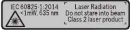
Ako TeKcbT Ha npedynpeHnHa Ta6ena He e Ha Baun e3NK, 3aeneTe npedn PbBaTa EKcNnoatauia OTrope Bbpxy Hero doCTabeHHa CTKepe Ha Baun e3NK.

He hacoBaIe Na3epHnIbU KbM Xopa I XNBOTHN IN BHHMaBaIte Da He NorIeHHe HEnocpeICTBeHo CpeSy Na3epHnIbU Nn Cpe-uy HerOBo OTPaKeHne. Taka MoKTe Da 3acnenIte Xopa, da npuHNrTe TpyOBN 3IOnOlyKn IIN Da PpeDnBnKeT yBpeJdaHe Ha OUnTe.
Ako na3epHnT nbu nonadHe B ouHTe, H3aTBopeTe Bb3MOxHo Ha-6bp30 nOTdpbNHete rnaBata cn OT na3epHnI nb4.
He n3BbPwBaIte n3MeHEnn no na3epHoTo o6OpyDbaHe.
He n3no3BaIte na3epHnTe ouHna KaTo 3aunTHn OuHna. Na3epHnTe ouHna cnykaT 3a no-do6po pa3no3HaBaHe Ha na3epHnra lyb; Te He npednaBAt OT na3epHo IbueHne.
He n3no3BaIte na3epHnte ouHa KaTO cBnueBn ouHa nn npu wOphipe. Na- 3epHnte ouHa He npedlaat nbHa UV 3aunTa n HaMaJIraBt Bb3npHeMaHeTo Ha uBeTobete.
OnyckaIte H3MePbATEHnHT ypeJa 6bJe peMOHTnpaH cMo OT KBAHnHnHpaHN TexnHn H cMo C n3NoJ3BaHe Ha opnHaHnH pe3epBnH qactn. C ToBa ce rapaTHp a 3ana3BaHeTo Ha cyHKnHTe, OcHpyraHn 6e3oNaCHocTt Ha n3MePbTeHnHnypeJ.
He octabnTe deca 6e3 npK nA3Op da pa6oTc H3MePbTeHnHa ype. Te MoRat HeBONHO da 3aclenrXopa
He pa6oTe c n3MepBaTeHnna ypeB CpeDa c nobHseHa onaCHOCT OT ekCnIO-3HH, B KOrTO HMa IeCHO3aIaNIMn TeuHOCTn, Ra3OBe Hn npaxOBe. B n3MepBaTeHnna ypeD MoT a Bb3HNKHaT NCKPn, KOnTO Da Bb3NpAMeHr npaxa Hn napTe.
Onncahne Ha npodukta n deHocTtA
Mon, OTBopeTe pa3rbBaAcaTc cTpaHnca C nHyprnte Ha n3MePbaTeHHy ypeH,doKaTo yeTePe bKOBOCTBOTO, oCTaBeTe OTBopeHa.
IpeHa3HauHne Ha eNeKtpOnHcTpymeHTa
I3MepBaTeHnHT ypeE npEpaHa3HaueH 3a I3MepBaHe Ha pa3CTOHH, DbJKNH, BnCOuHH, HAKIOHN 3a I3UncJIbaHe Ha IILOU IN O6eMn.
I3mepBaTeHnHrT ypeE e noxOJa3a pa6To Ha OTKpHTo N B 3aTbOpEHn PomeeHn.
(5) NycKOB npeKbcBaU [Φ
(6) BytoH 3a 3anaMeTBAHe [
(7)Функионаненбун [Func]
(8) ByToH MmHyc [-]
(9) Kanak Ha rHe3dOTo 3a 6aTePm
(10) ByToH 3a 3actOpraBe Ha KaNaka Ha rHe3doTo 3a 6aTePm
(11) CepHeH Homep
(12) IpeynpeintenHa Ta6eKa 3a Ja3epnna lyu
(13) Pe360Bn OTBop 1/4"3aCTaTb
(14) Pnemaa nea
(15) OToBp 3a na3epnnaIbU
(16) Na3epHa qeIeBa nloUka
(17) Na3eprHn ouHa
(18) CTaTHB
A) N3o6pa3eHnTe Ha 0nHcHnTe OONbHNHTENn npncnoc6neHn He ca BKnIOueHn B cTaNapThata OKOMNKeKTOBka Ha ypeHa. N3ePNaTeEN CnncbK Ha DOnbHNHTENHn Tnpncnoc6neHn MoKeTe Da HamepHn CeBTBtHO B KATAIora Hn 3a DoNbHNHTENn npncnoc6neHn.
Toka3BaHn eIeMeHTn (u36op)
(a) CtaTycha neHtA
(b) OTnpaBHa paBHHa 3a H3MepBaHeTo
(c) CbCToHHne Ha 6aTePnraTa
(d) PeDoBe 3a H3MepeHHTe CTOnHOCTN
(e) PeДза peэztata
(f) ΦyHKUIN 3a n3MePBAHe
(g) Ione 3a bTbHa Hau KaIOHa
336|BbIrapckn
(h) OCHOBHn HAcTpoKn
TexHHueckn daHHN
BnHaTcMeHnTe BcNk6aTePN,peCn. AkymyNaTOPHNTE 6aTePN eHOBpemeHNO. N3- ION3BaIe cAmO 6aTePN HnAkymyNaTOPHN 6aTePN Ha eINH Ppon3BOInTe n C eHaKbB KanaHTet.
Korato Hama da n3no3BaTe n3MepBaTeHnH ypei npoBxHnHo BpeMe, n3BaxdaTe 6atepHnte, pecn. akymyNatopHnte 6atepHn. Pn npoBxHnHo cbXpaHbAhe bypea 6atepHnte n akymyNatopHnte 6atepHn MoRaT da KopoDnpat n da ce camOpa3peJr.
Pa6ota c eNeKtpOnHcTpymeHa
Nyckahe Bekcnoataa
He octabnte ypea BkHouen 6e3 ha3Op; cnei KaTO npKIOUHTe pa6Ota, ro n3KnIOuBaIte. Dpyr nnca MoRat da 6bDaT 3aceneHOn Tna3epHnA IbU.
PpeNa3BaTe H3MepBaTeHnHn np6op OT OBnXnBaHe n DnpeKTHo nonaHa Ha CJIbHcEBN JbH.
He n3naraTe n3MepBaTeHnna ypeHa ekCTpeMHn TemnpaTpyn Hn pe3Kn TneNepaTyPh npomeHH. Hanp. He ro ocTaBnTe npOdbnKHTeHNO BpeMe BA bTOMO6n. Pn rOleMn TemnepaTyPhn pa3nKIOcTaBaHTe n3MepBaTeHnArypeD pbpBO da ce TeMnepnpa nped Da ro BKIOuHTe. Pn ekCTpeMHn TemnpaTyPhn Hn rOleMn TempePaTyPhn pa3nKIOtuHocTTa Ha n3MepBaTeHnna ypeD MOKe Da Ce BLOUHN.
H36yBaTe CnHn yIapn Hn H3nyckaHe Ha H3MepBaTeHHn ypei. Cnei CnHn BbHsHm MexaHnUHn Bb3deIcTBn Bbpxu H3MepBaTeHHn ypei, Ippei Da npOdbJnx-Te pa6ota, BnHaTn Tp8Ba Da n3nbHnBaTe npOeDpyaTa no npOBepKa Ha ToUHocTt My (Bk. .PiobepKa Ha ToUHocTt Na KaIIb6pHpAHe Ha H3MepBaHeTo Ha HaKnOH (Bk. fHr.E1-E2), CtpaHnua 346).
BknIOUbaHe n3KnIOUbaHe
-3a BKNIOUObHe Ha n3MepBaTeHnHa ypei Ha na3epa HATncHeTe KpaTKoTpaHb6yToHa 3a n3MepBaHe (2) [A
-3a BKNIOUBAHe Ha H3MepBaTeHnHnHCTpyMeHT 6e3 Ja3epa HaTNChe Te KpaTKOTpaH NoCKOBn IpeKbCBaU (5) [Φ
He hacouBaIte na3epHnI NbU KbM Xopa HIN KHBOTn; He rneJaTe cpeu y na-3epHnI NbU, cbso n OT rOJMAo pa3CTOHHne.
3a n3KlIOUBaHe Ha n3MePBATeHnIypeI 3aApBxTe IyckOBnI ppeKbCBAu (5) [O] HATNC-HaT.
Прии ИЗКлюва He Na ИЗМерВateЛния урет Нампашиte ce B NaMeTTa CTоHOCt И HabTe pОйКITE ce 3ana3BaT.
H3MepBaHe
CleB BkIIOUBaHe n3MepBaTeJIHHrT ypeD ce HAMnpa B pexHm 3a n3MepBaHe Ha IbJxHn. 3a npyra fynKunna Ha n3MepBaHe HATNCheTe 6yToHa (7) [Func]. N36peTe JeaHata fynKUnna 3a n3MepBaHe c 6yToHa (3) ([+] nnn 6yToHa (8) [-] OT (BXK..FynKUnna 3a n3-MepBaHe", Ctpanuca 340). AKTINBpuAte fynKUnnaTa 3a n3MepBaHe c 6yToHa (7) [Func] nnn c 6yToHa 3a n3MepBaHe (2) [
CleB BkIIOUBaHe 3a OTnpaBHa paBnHa aBTOMaTHuHO Ce yCTaHOBra 3aHnT pb6 Ha n3-MepBaTeHNHa ypei. 3a cMaHa ha pepeeHTHaTa paBnHa (Bx.,N3bpaHe ha pepeeHTHa paBnHa (Bx.ΦnR.A)“, CtpaHnua 339).
DOnpeTe n3MepBaTeHnHa ypeIdo JeenaHaTa HauaHa ToUka 3a N3MepBaHeTo (HaNP. cTeHa).
Yka3aHHe: Ako n3MepBaTeHHnT HnCTpyMeHT Ce BkIIOuN C nycKOBn IpeKbCBaU (5) [Φ], HaTHcHeTe 3a KpaTKo 6yToHa 3a N3MepBaHe (2) [3a Da BkIIOuHTe Ia3epa.
3a cTApTnpaHe Ha n3MepBaHeTo HATnCHeTe 6yToHa (2) [Cnei TOBa na3epHnIy TbU ce n3KnIOuBa. 3a CneiBaIo n3MepBaHe NOBtOpTe Ta3n npOeDpya.
He hacouBaIte na3epHnIb4 KbM xopa nnXKNBOTHN; He rIeJaTe cpeuy na-3epHnIb4, CbIoo n OT rOJAMo pa3CTOAHne.
Yka3aHHe: N3MepeHaTcToHOCt O6nKHOBeHO Ce NOBBA CneI 0,5 s Hr He No-KbCHO OT OK.4s.PoDbJXHTeHHocCTTa 3aBNCN OT pa3CTOAHNETO,CBEITNIHHITE CbOTHOWeHnI HOTpaKaTeHNTE CBOIcTBa Ha ceneBaTaNOBbpXHOCT.CNeI pNkLIIOUBAHe Ha N3MepBaHETO Na3epHnT NbCe N3KJIIOUBA ABTOMaTHUHO.
I36npaHe ha pepepeHTha paBHnHa (Bx. qnr. A)
3a n3MepBaHeTo MoKeTe Da n36npaTe MeKdTy TpH pa3nUHN HaayAHH paBHHN:
-3aHnna p6 ha n3MePbTeHnna ypei (HaNP. npn dOnnpaHe do cTeHa),
-
npednna pb6 ha n3mepBaTeHHy ypei (Hanp. npn n3mepBaHe oT pb6a Ha Maca),
-
ζηntbpa Ha pe36OBnA OTBop (13) (Hap. npn n3MepeBaHe cbc CTaTHB)
3a n3bop Ha hauanhata toka haTnche6ytoha (4). N36peTe keenahata pepepeHTha paBnHa c 6yToHa (3) [+] nn 6yToHa (8) [-nn C 6yToHa (4)]. BnHa rCneBkIIOUbaHe 3a HauanHa toka ce n3bnpa 3adHnT pb6 Ha n3MepBaTeHHn ypei.
340|BbIrapckn
MeHIO "OChOBn HactpoiKn"
3aДа пonaднete в MeHIOTo "OCHOBHn HAcTpoiKN"(h), 3aIpbXTe HaTnCnat 6yToHa (7) [Func].
H36peTe cboTBeTHaTa onuHa n CToHocTtA h.
3aДаизлесеTe OT MeHIOTo "OCHOBHn HacTpoiKn",HaTNCHeTe NyCKOBn npeKbCBaU (5) [6].
OcbetneHHe Ha dncnpe
OcbetneHneto Ha dnCnpe E BkIoueHO. Ako B npoBnKeHne Ha 20 cekyHn He 6bHe haTncnat 6yToH, 3a npedna3BaHe Ha 6atepHnte/aKymylatopHnte 6atepHn OCBetneHneto Ha dnCnpe Ce HamaJIraBa.
Функциизмерван
H3mepBaHe Ha dbnKHHN
H36peTe H3MePbAHeTo Ha DbJxHa1.
3a BKNIOUbaHe Ha Ia3epHnIbU HaTNCHeTe KpaTKOTpaHOb 6yToHa 3a N3MepBaHe (2) [▲].
HaTnchete 3a n3MepBaHe 3a KpaTko 6byToHa 3a n3MepBaHe (2) [N3MepeHata cToHocT ce n3O6pa3raBA BdoHaT auct Ha dncnne.
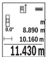
IobTapnTe roPHTe CTbKN npH BCaKO CneBaIo n3MepBaHe. NocnEDHO n3MepeHaTa cToHOCt Ce HAMnpa Na-DoNy Ha DnCnpe, PpeDnocLeHaTa - Ha He I T.H.
HenpeKbchaTo n3MepBaHe
Pn HnpeKbCHaTo n3MepBaHe n3MepBaTeHnT ypeD MoKe Da 6bJe npMeCtBaH CnpraMo ueBATA TOka, KaTO n3MepeHata cToHocCT ce aKTuAn3Hpa BceKn O,5 s. HanpHmepMOxte Da ce OTdAeHTe OT CTeHa Ha XeHaHOTo pa3CTOAHne, TeKyUTo pa3CTOAHne Ce BHXda HnpeKbCHaTO.
H36epete HnpeKbchaTo H3MepBaHe.
3a BKNIOUBAHe Ha Ia3epHnIbU HATNCHETe KpaTKOTpaHObyToHa 3a N3MepBaHe (2) [▲].
Haocuete H3mepBaTeHnH ypei, DOKaTO Ha dncnneCe H3o6pa3n CToHOCCTHa JKeNaHaTa DbLnKnHa.
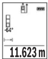
Upe3 KpaTko HaTnCKaHe Ha 6yToHa 3a n3MepBaHe (2) [cnpate HenpeKbCHaTOTO n3MepBaHe. Tekyo n3MepeHata cToHocTe n3o6pa3raBa dony Ha nCnner. NOBTOHO HA TnCKaHe Ha 6yToHa 3a n3MepBaHe (2) [ ] cTApTnpa HnpeKbCHaTOTO n3MepBaHe OTHOBO.
HenpeKbchaTOTO n3MepBaHe ce n3KnIOuBa aBTOMaTHUHO cnei 5 min aB- TOMaTHUHO.
H3mepBaHe Ha nlou
H36epete n3MepBaHe Ha nlou
Cne ToBa H3MepTe NocNeIOBATEHNO SHnPOUHNaT NbIXNHaTa Taka, KaKTo H3MepBaTe bIXNHa. Na3epHnT NbOCTaBA BKJIoueH MekDy DBeTe H3MepBaHH. OTecKaT, KOrTo Tpa6Ba Da 6bIe H3MepeHa, MHa Ha CnMbOla 3a H3MepBaHe Ha IIOu

Ibpbata n3MepeHa cToHocCT ce NOKa3Ba B rOpHaTa qAcT ha DnCnpe. Cnei npKIOUbaHe Ha BTOPO To n3MePbaHe PIOuTa ce N3UcNBA aBTOMaTHNo Hc NOKa3Ba.Ha-OTdOly Ha DnCnpeA cToI pe3yNTaTbT,HaHero - cToHOCHTte OT OTeHNHe n3MepBaHHa.
H3mepBaHe ha 06em
H36epete H3MepBaHe Ha o6em
CneToBa H3Mepete NocJeIOBaTeHNO IInPOUHaTa, bJnxHATA H BnCOUHaTA, KaKTo Ce H3MepBat dJxHH. Na3epHnT IbU OCTaBA BKIOueH MExdy H3MepBaHnTA. OTecuKaTa, KOrTO Tp6Ba Da 6Be H3MepeHa, MfA Ha CmB0N 3a H3MepBaHe Ha o6em
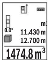
Ibpbata n3MepeHa cToHocT ce NOKa3Ba B rOpHaTa yAcT Ha dncnner. Cnei npNKIOUbaHe Ha TpeTOTO n3MepBaHe oBeMbT ce H3uNCnBa aBTOMaTHNo Hc POKa3Ba Ha dncnner. Han-OTOny Ha dncnner cToN pe3ynTaTbT, HAd Hero - cToHOCHTe OT OTdENHtE n3MepBaHHa.
HnDnpeKTHo N3MepBaHe Ha pa3CTOaHne
Pa3noIarate c Tprn cyHKcHn 3a HnDnpeKTHo N3MepBaHe Ha pa3CTOJHne, KOHTo MOrat da 6bDat npnilaraHn B pa3NIuHn CNTyaCnn.
HnIneKTHOTo H3MepBaHe HaNbJxHa CnyJx 3a H3MepBaHe Ha pa3CTOHHa, KOHTo He MoRat Da bDaTn H3MepEHn HenocpeDCTBeHO, Tb KaTO NIO PbTa Ha NbUa HMa IpePAnTCTBHe Hn TbKaTO B KpaHaTa TOka Hma OTpa3raBaUa NOBbPxHOCT. To3n MeToD Ha H3MepBa- He MoXe Da bDe npInIoXeH cAmO BbB BepTKaJIHO HappAbHe. BcKO OTKIOHeHne B XOpN3OHTaIIHO HApBaJIeHHe BOIN DO yBEnuHaBe Ha rpeWKaTA B H3MepBaHeTO.
342|BbIrapckn
Yka3aHHe: INdIpeKTHOTO H3MepBaHe Ha pa3CTOHH e BnHaHr NO-HEToHO OT dIpeKTHOTO. CbflacHo npHUnHa ha pa6oTa rpeKHTe npH3MepBaHeTO MoT a ca No-roMeN OT Te3n pRn dIpeKTHO H3MepBaHe. 3a IIOO6PraBaHe Ha TOUHOCTTa Ha H3MepBaHe npEINOpbUBAme PON3BaHeTO Ha cTAtNB (He e BKIOueH B OKOMJIeKTOBkata).
MexdyOTdennHte N3MePbAHnIa3epHnTlbU OCTaBA BKIOueH.
a) INHnpekTHo H3MepBaHe Ha BncoounHa (Bx. fnr. B)
H36epete HnDnpeKTHo H3MepBaHe Ha BnC0uHa
BnHmBaIte H3MepBaTeHNrT ypeI da e Ha cbSata BnCOuHa, Ha KOaTO e DOnHaTa KpaH a ToKHa Ha N3MepBaHata BnCOUHa. CneI TOBa 3aBbPTeTe H3MepBaTeHNrY ypeI OKoLo HauAnHaTo TocKa "1"(N3O6pa3eHa Ha NcCnIe KaTo YepBeHa nnHra).
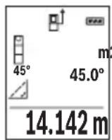
CneI npKIOBaHe Ha n3MepBaHTo pe3yIaTbT 3a TbpceHTo pa3CTOHNHe "X" Ce n3nncBa Ha peHa (e). N3MepeHHTe cToHocTH 3a pa3CTOHNeto "1" n bIbna "a" ca n3nncAHn Ha peDoBeTe (d).
6)Дбоин Ho HnDnpeKTHo n3MepBaHe Ha BncoHnHa (Bx.Фг.C)
N3MepBaTeHnHTypeI MoKe Ia N3MepBa HnDnpeKTHO BCaKaBn pa3CToHn, KOnto Ca BbB BepTKaHaTa paBHHa Ha N3MepBaTeHnrypeI.
H36epTe IBOHIO INHINPEKTHO H3MepBaHe Ha BnCOUHa
I3Mepete OTeeKHe "1" H "2" Ta3n IocneIOBaTeJIHOCT, KaKTo 06NKHOBeHO I3MepBaTe IbJxHn.
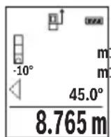
CneI npKIOBaHe Ha n3MepBaHTo pe3yNTaTbT 3a TbpceHOTo pa3CTOHNHe "X" ce n3nncBa Ha peDa (e). N3MepeHnte CTOHOCTH 3a OTceKHTe "1", "2" n bTbna "a" ce n306pa3raBAt Ha peDObTe (d).
BHHMaBaIte npn BCnUKn eHnHnHn H3MepBaHnHa nHdNpeKTHOTO ONpeJenHe Ha BnCOuHa OTnpaBHaTa paBHnHa (HaNP.3aHnT pb6 Ha n3-MepBaTeHNHa ype) da octaHa HnPoMeHeHa.
B) INHnpeKTHo n3MePbAHe Ha nbIaHa (Bx. qnr. D)
H36epete HnDHeKTHo H3MePBAHe Ha DblJxHa
BnHmBaIte n3MepBaTeHNrT ypeI da e Ha cbIaTa BnCOUHa, Ha KOrTo e TbpcHeTAt KpaHb TouKa Ha n3MepBaHeto. CneI TOBa 3aBbPTeTe n3MepBaTeHNrYpeI OKOLO OTpPaBHATA paBHnHa H3MepTe pa3CToAHnEto "1" NO NaHHa, IIO KOITo n3MepBaTe DblJxHH.
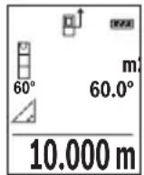
CneI npKIOBaHe Ha n3MepBaHTo pe3yNTaTbT 3a TbpcHOTo pa3CTOHNHe "X" ce n3nncBa Ha peDa (e). N3mpeHHTe cToHOCTH 3a pa3CTOHNeto "1" n bTbna "a" ca n3nncAHn Ha peDoBeTe (d).
H3mepBaHe Ha HAKIOH/UNΦpOBA IIN6eNa
H36epTe H3MepBaHe Ha hKnIOH/uzΦpOBA nn6ena
I3mepBaTeHnHrT ypeCe IpeBkIIOUBa aBTOMaTHuHO MeJy DBe CbCTOHHN.

UHpOBaTa H6eLa CnyxN 3a npOBepKa Ha XOpN3OHTaIHOTo NIN BepTHKALHO NOpaBnBaHe Ha oBeKT (HaNP. MnaIIHa MaunHa, XlaIINIK N T.H.).
Korato NaKIOHbT npeBnWaba 3^ ,HaNcNlEe CBeTBa cepBeHaTa ToKa.
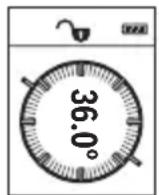
I3MepBaHTo Ha HAKLOH clyxN 3a H3MepBaHe Ha bTbN Ha HAKLOHeH NOBbpxHOCTn HIN MNCJIeHN IpaBn (HaNP. Ha cTbN6n, npapaneN, CBOIOBe 3a Me6eN, pni pnekapBaHe Ha Tpb6n nDp.n).
KaTo OTnpaBHa paBnHa npi n3MepBaHeTo Ha haKIOH cIyXn IaBata CtpaHa Ha n3MepBaTeHNHa ypeI. Ako nO BpeMe Ha n3MepBaHeTo dncIeT 3aNoUHe Da Mna, n3MepBaTeHNHa ypeI e 6nI HaKIOHeH TBbpDe
CINHO CTpaHnHNo.
Функши no 3anaMeTЯBaHe
CTOHOCTTa,peCn.KpaHnT pe3yIITAT OT BCaKO npHKNIO H3MepBaHe aBTOMaTHUHO ce 3aIINCBa.
3anaMeTeHcSTOHOCTH
Morat da 6bdaT 3aapanMeTeHn H3BnKaHn HaH-MHOrO 20 cToHOCTH (H3MepeHN nn H3- uncenH).
Cb6npaHeHa cTOnHOCTH
CneHnT npHmep onncBa cb6npaHeto Ha nnoi:
YcTaHOBete NOBbpxHocTtA cBflaCHO pa3dEIN "NImepBaHe Ha NOBbpxHocTn" (BX. ,N3mepBaHe Ha nlou", CtpaHnca 341).
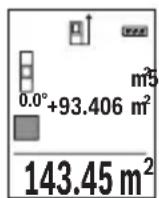
HaTnche6byToHa(3)[+].HaIncnpeCe noka3BaT n3uNCHeHata nIoU H CnMBoJIbT" ^+
HaTnchete 6yToHa 3a H3MepBaHe (2) [3a Da CTapTpate HOBO H3-MepBaHe Ha nlou. YcTaHOBeTe NOBbPxHocTtA cbrIacHo pa3dEn "H3MepBaHe Ha NOBbPxHocTH" (BxK..N3MepBaHe Ha nlou", CtpaHnua 341). KOrato npHKIOUHy BTOPOTo H3MepBaHe, pe3yNTaTbT OT Hero ce NOKa3Ba Do
Iy ha dncnne. 3a da nokkete pe3yntata, HATNCHEte OTHOBO 6yToHa 3a N3MepBaHe (2) [A].
Yka3aHHe: Pn H3MepBaHe Ha DbJxHa BeDHa ce noka3Ba pe3yTbT.
3a n3n3aHe oT pexmHa hcb6hpae HaTncHe 6yToHa (7) [Func].
N3BaXdaHe Ha cToHocTH
3a n3BaJdaHe Ha cToHocTn HATncHete 6yToHa (8) [-]. HaunbTa ha paBoTa e aHaonu. eyen Ha "DobabJe Ha cToHocTn".
N3tpnBaHe Ha N3MepeHH CToHocTH
Upe3 KpaTko HaTnCKaHe Ha NysKOBn IpeKbCBAu (5) [MOKeTe Da H3Tpne Te Bbb BCnKn FyHKun 3a H3MepBaHe NoCneHDo yCTaHOBcHata CTOnHOCT. Upe3 MHOrOkpaTHo KpaT
KOTpaHNo HATnCKaHe Ha NyCKOBnI pKeBcBaU (5) [Oce n3TpNBaT B o6paTHa IocneoBATEENHOCT N3MepeHnte PpeN TOBa CTOHOCtN.
CmHaHa MepHaTa eHHNu
OCHOBHata MePHa eHNHuae "m" (MeTbp).
BkIIOUeTe I3MEpBaTeHnHypeJ.
3a da nonadhe T MeHIOTo "OCHOBn HAcTPOIKN", 3aDpbXTe HaTNCat 6yToHa (7)
[Func].N36epete"ft/m".
HaTnCHeTe 6yToHa (3) [+] nHn 6yToHa (8) [-], 3a Da CMeHnTe MePaTa eDHHuA.
3a n3n3aHe OT Ta3n ToUka OT MeHIOTo HaTNCHe Te NsCKOBn IpeKbCBauch (5) [Φ N36paHaTa MepHa eINHua Ce 3aNa3Ba H CneI N3KJIuOvBaHe Ha N3MePBATeHNH ypeI.
BkIIOUbaHe n 3KIOUbaHe Ha 3ByKOBnCnHnA
Ipo noopa3bnpaHe 3BykoBata CnHaHn3aun e BklnoueHa.
Bknloye H3mepBaTeHnH ypeJ.
3aДа nonaHHeTe B MeHIOTo "OCHOBn HAcTpoKn", 3aIpbXTe HaTnCHaT 6yToHa (7) [Func].ИЗбepete 品 .HATncHete 6yToHa (3) [+] nIn 6yToHa (8)[-], 3aДаВКЛIOUHn I3KJIQUHTe 3ByKOBaTa CnHAn3aUN.
3a H3nH3aHe OT ToKkTa OT MeHIO To HaTNCHeTe 6yToHa 3a H3MepBaHe (2) [4nH nyckoBn IpeKbCBauch (5) [6. H36paHata MepHa eHNuca ce 3ana3Ba n cIeN H3KnUoyBaHe Ha H3MepBaTeHnH ypeJ.
Yka3aHna 3pa6oTa
06uH yka3aHn
IIO Bpeme Ha n3MepBaHe npHemaaata Lea (14) H OTBOpBT 3a H3XoJaun Ja3epeH nbU (15) He Tpa6Ba Da 6bDat 3akPnBaHH.
IIO BpeMe Ha H3MepBaHeTo ypeBt He 6nBa Da 6bJe IpeMeCTBaH. 3aTOBa IIO Bb3MOX-HOCT DOIIpaTe H3MepBaTeHNH YApeD IO 3dPaBa OONOPHa IOBbpxHOCT.
ФakTopи,Влияши Вьрху ДиANA30Ha Ha N3MepBaHe
Диаэзовьт ha ИЗмервае 3aВИСН OT CBETПИHHTe yCIOBЯ и OTPa3nteHATA cnOCO6HOCT Ha NOBbpxHOCTTa,do KOrTo ce Мepn.3a no-Do6po BIXJaHe Ha Na3ePnHa IbU npN CINHa OKoJIHa CBETIIHa H3NoI3BaIte OUnIata (17) (He ca BKJIIOUeHN B OKOMJIeKTOBkA-Ta)илazepHATA ueIeBa ПLOUka (16)(прнаджHOT)иИЗЗeHYe Te ZeIeBaTЯ NOBbpXHOCT.
346|BbIrapckn
ΦaKTopn, BnHaeuBbpxy ToUHocTtHa H3MepBaHeTo
Bb3 OCHOBA Ha non3BaHnte npn n3MepBaHeTo fns3Nueckn eefektn He morat da 6bDat n3-KIIOUeHN Bb3HNKBAuN rpeuKN npn n3MepBaHeTo do pa3NJuH N IOBbpxHOCTN. B TOBa YNCNO BIN3aT:
- npo3paUHH NOBbpxHOCTn (HaNP. CTbKJIO, BOda),
- Otpa3BaunIOBbpxHOCTn (HaNP. NOIpaHm MeTaHn IpeDMeH, CTbKNo),
- nopectn NOBbpxHoctn (Ha np. 30launOHm MaepnaH),
- NOBbpxHocTn C rpaNaBa C tpyKtpya (Ha np. rpy6a Ma3nIka, eCTeTBen KaMbK).
Iprn Heo6xOJHMOCT npn H3MepBaHe Do TaKINbA NOBbpxHOCTN 3IOJI3BaIe OTPa3RAUa MepTeHa IIouka (16) (He e BkIIIOueHa B OKOMNJIeKTOBKaTa).
OcBeH TOBa rpeuHn NOKa3aHnMOrat Da Ce NOnyuat npn N3MePBAHe Do NOBbpxHOCTN, KOnTO Ca nOd bFbI.
ToHocTtHa n3MepeHaTa CToHocT MoKe Da Ce NOBnRe CbO TaKa OT HAnuHeTo Ha Bb3dUshn CNoEBe CbC cnIeH rpaIeHT Ha TempePaTypata nn INHdIpeKTHN OtpaxeHna.
PoiIbpxKaIte I3MepBaTeHnIypeD BnHaHn UHCT.
He nToonBaIte H3MePbTeHnHyapeD BbB BOa IIN dpyrTeuHOCTN.
N36bpcaBte 3aMbpCBAHnHTa C MeKa,NeKO HbNaXHeHa Kbpna.He N3no3BaTe no- uNCTBaU npenapATn nn pa3TbOpnteHH.
Othacrte ce cneuaHNO KbM npHemaata nea (14) Cbc cbto TO BHMaHne, C KOeTo ce OTHACrTe KbM ouHa nn oEkTHB Ha foToanapat.
B cnyuah Ha dephiekt nnn peMOHT n3npaTe Te n3MePbTeHnna ypeB B OTOpn3napaH cepBN3 3a eIeKTPoHHCTpyMeHTn Ha BoW.
KnnehtcKa cnyy6a n KOHCyItaun oTHocHo ynoTe6ata
CepBn3bT Ⅲe OTROBOpHa BbnpocHTe Bn OTHOcH pEmOHn I NOdApBXKa Ha 3aKyIeHH O T Bac npOdyKT, KaKTo n OTHOcH pe3epBHN qactn. POKOMNoHENTn YepTeKn I INΦopMaun 3a pe3epBHIne qactn Ⅲe OTKpHeTe N Ha: www.bosch-pt.com
348|BbIrapckn
EkHbT NO KOHCyIaun OTHOCHO yNoTe6aTa Ha Bosch ue Bn NOMorHe c yOBOCTBHe npn Bbnpocn 3a HauNte PPOdyKTn N TexHIne akcecoapn.
MOnI, npn Bbnpocn n npn npbUbaHe Ha pe3epBn qactn BnHaH nocOuBaTe 10-ncpeHH KATAIOXeH HOMeP, n3nncan Ha TaBeNKaTa Ha ypeDa.
Блгария
Robert Bosch SRL
Service scule electrice
Strada Horia Macelariu Nr. 30-34, sector 1
013937 Bucuresti, Romania
TeI.: +359(0)700 13 667 (BbIrapckn)
ΦaKc: +40 212 331 313
Email: BoschServiceCenterBG@ro.bosch.com
www.bosch-pt.com/bg/bg/
БракуВанe
I3MepBaTeHnHrT ype,doBbHHTeHnHte npncnoc6neHn H onakOBKnte Tpr6Ba da 6b- dat nOIOJKeHH Ha ekOJIOrnHa npepa6OTka 3a ycBOraBaHe Ha cbDbpKaunTe Ce B Tnx cyPOBHH.
He n3xBbprnTe n3MePbaTeHnTe ypeN n akymyIaTOPHnTe 6aTePnN/ 6aTePnTe np6bTOBnTe OTnabu!
Camo 3a cTpaHn ot EC:
CbIacHo eBponecka dIpeKTHBa 2012/19/EC n3MepBaTeHNte ypeN, KOHT He Morat da ce noI3BaT noBeue, a cbIacHo eBponecka dIpeKTHBa 2006/66/EO nobpeHn Hn HxabEHn o6KnHOeHn Hn akymyataPn 6aTePNn Tpa6Ba Da ce cb6npaT n pedeBa 3a OOn3OTBOPBAHe Ha cIbPkaUHTe Ce B T8xCypOBHH.
MaKeDoHcKn
БeЗб endocnн habomehn

CnTe yNaTCTBa Tpe6a Da ce npoHTaaT Ha da Ce BHHMaBa Ha HNB, 3a Da moKe 6e36eHNO H 6e3 onachocT da pa6oTHe CO MEPHNOTypeI. Dokonky MEPHnotypeI He ce KopncTH cornaCHO npnoXKeHIne HHcTpyKcHm, MoKe Da ce HapuHn FyHKunjata Ha BrpaDeHnTe 3aHTHTM MexAHN3Mn BO MEPHnotypeI. He rO owTeTyBajte
npeynpeyBaKTe 3Naun. IOBPO UYBAJTE HN OBNE YNATCTBA N I PEPADETEN 3AEHNO CO MEPHNOT YEPI.
BHHMaHHe -doKoNky KopnCTHe npyH ypeH 3a noDecyBaBe n paKyBaBe oCBeH OBd He HabeDeHHTe Hn NOnHaKBn NoCTaKN, OBA MoKe Da IObeDe Do onaCha H3IOXKeHocT Ha 3paueHe.
MepHnot ypeI ce nCnpaCyBa co npedynpeDyBauchn 3nK (o3NaeHO Ha npHKa3OT Na MEPHnot ypeI ha rpaΦnKata cTpaHa co 6poj (12)).
IEC60825-1:2014
<1mW.635nm
Laser Radiation
Do not stare into beam.
Class 2 laser product
Iokonky TeKCTOT Ha HanelnHcata 3a npedynpeyBahe He e Ha Baunot ja3NK, Bp3 Hero 3aeneTe ja HanelnHcata Ha Baunot ja3NK nped npBaTa ynotpe6a.
He ro hacouybajte nacepckhot 3paK KOH Iuca HIN XHBOTN H hemoje N Bue camnte da rneate BO dpekTHnOT Hn peqntnpauchot nacepckn 3paK. Taka MOKe Da rN 3acnepnte IucaT, da npedn3BnuKeTe Hcpekn HIn Da rN OWTETNe Ouyte.
Iokonky nacepcknot 3pak docnee do ouHTe, BeHaaw Tpe6a da rH 3aTBOpHTe n da ja TprHete rnaBata od nacepcknot 3pak.
He npaBete npomeHn ha naacepcknoType.
He rK KopnCTe Nacepcknte 3aHTTHN OvHna KaKo 3aHTTHN OvHna. Napccknte 3aHTTHN OvHna cnykat 3a noDobpo pacno3HaBaHbe Ha napccknot 3paK; cenaK, Tne He wHTtAT oJ nacepckto 3paueHbe.
350|MaKeDoHcKn
He rH Kopnctete Nacepcknte 3aHTTHN OCHNA KAKO OCHNA 3a COHcE HNN NAK BO coo6paKajot. Nacepcknte 3aHTTHN OCHNA He daBaat celocHa UV-3aHTTA n To HamaNyBaAT npepno3HaBaHBeTo Ha 60n.
MepHnot ypeD cMee da ce nonpaBa caMo od CtpaHa Ha KBaHnKHyBaH CtpyuH nepcoHaN h camo co opHnHaHn pe3epBHN deNoBn. Camo Ha Toj HauHH Ke 6uJeTe cnrypHn BO 6e36eHnOCTa Ha MEPHnot ypeI.
He rno octabajte decaata da ro kopnctat nacepcknot mepeh ype3 na30p. Be3 na30p, Tne moxe da 3acnenat npyrn nua.
He pa6oTeTe co MEPHnot ypeD BO OKONHa KaJe NoCTOn ONaCHOCT Od ekCnNo3Ha, KaJe HMa 3aNaANBn TeuHOCTn, rac Hn npaunHa. MEPHnot ypeD CO3daBa NcKpN, KOH MoKe Da ja 3aNaIaNt ppaTb IIN napeata.
Onnc Ha npon3BODOTn nepopmancnte
OTbopeTe ja npeklonenata cTpaHnca co npka3 Ha MEPHNOT ypei n dpjKeTe ja OTbopeHa DoNeKa rO uHTate ynatCTBOTO 3a ynoTpe6a.
Hameheta ynotpe6a
Mepnnot ype n e HameHET 3a MepeHe Ha daJeHH,doJxHH, BscHH, paCtoJaHja, KocHH N 3a PneCMeTyBaHBe Ha NOBpUHH IN BOJyMeHH.
Mepnnot ype n oroen 3a KopncTeHe BO BHaTpeWeH n HaBOpeweH npocToP.
Nlyctpaunja Ha KOMnoHeHTN
HymepnpaheTo Ha cInKte CO KOMnoHeHTe ce OndecyBa Ha npka3OT Ha MepHnot ypeHa rpaqnuKaTa CTpaHnca.
(1) EkpaH
(2) MepHo konue [
(3)Плес konue [+]
(4) Konque 3a n36pahe ha pepepeHTHO HNBO
(5) Konque 3a BknyuBaHbe-ncknyuBaHbe [Φ
(6) Konque 3a Memopnpahe [p]
(7)ФункионаннКончe [Func]
(8) MInHyc KOnue [-]
(9) Kanak Ha nperpadaata 3a 6atepi
(10) ΦИКСИРаБе Ha KanaKOT OД npERpaDATA 3a 6aTePnN
(11) Cepnckbproj
(12) PpeDynpEduBaUKN 3HaKaIacepoT
(13) 1/4"-Haboj Ha cTaTHBOT
(14)Приемна leka
(15) Ⅲne3HaIacepcknO3paK
(16) Nacepcka ueHnHa ta6naA
(17) Naacepckn 3aunTHn Ounna
(18) CTaNB
A) NynctpnpaHATA HNn ONHsHa ONpeMa He e JeI ON CTaNdAPDHNO6eMa Hcnpaka. Uenochata onpeMa moKe da ja HajTe BO hawata Pporpama 3a onpeMa.
MeHn ,OCHOBHn noCTaBKn"
3aДаВлeЗЕТБОМEHITO,ОсHOBи NOCTaBKN"(h),Држete ro npHTnCHaTO KOnчeto (7) [Func].
I36peTe ja ODHcHaTa OCHOBHa NocTaBka H HeJ3HnHOTo NOpecyBaHe.
3aДаиЗпeTeОмMeHTo „OCHOBнnoCTaBKn“, npHTnCHeTe Ha KOnyTe 3a BknyBaHbe-NCKnyBaHbe (5) [Ф.
OcbetnyBaBeHaekpaHOT
OcbetnyBaHbTo Ha ekpaHot e NoctoJaHO BKnyeHo. OOKOnKy He npHTncHe Ta KOnyTe, OCBetnyBaHbTo Ha ekpaHot ce 3aTeMHyBa No OKony 20 cekyni 3apaNn 3auTnTa Ha 6atepnite.
MepnФyHKcH
MepebeHaDOnJxHH
H36peTe MepeHe Ha DOnJxHHI.
3a da ro Bknyute nacepckno 3paK, npntncheTe KpaTKo Ha MepHOTO KOue (2) [
3a MepeHe npHTncHe T KpaTko Ha MepHOTo KOnue (2) [H3MepeHaTa BpeHocT Ke ce npKakKe dony Ha ekpaHoT.
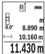
3a cekoe nohatamOHO Mepehe NOBTOpeTe rnopeHaBeDeHHTe uekopn. IocneHaTa H3MepeHa BpeHOCCTOn dony Ha ekpaHOT, a npetIOcneHATA Na Hea NTH.
KoHTnHynpaHOMepeBe
При КОТИнунуразно Мереьe, Мернnot урд може релаTNBHO DA ce ДВЖИ KOH ueNTa,пriшTOиЗмеренATA ВрED noct ke ce axypupa Ha cekoN O,5 s. Ha np. може дca ce OДалечte Ha Hekoe pactojaHne od SHIDOT, a MOMENTANHOTo pactojaHne cekoraw Ke 6nnde uHTINBO.
H36peTe KOHTINHynpaHO MepeBeI.
3a da ro Bknyute nacepckno 3paK, npntncheTe KpATKO Ha MepHOTOKonue (2) [
Движete ro Мернот уретдддда He ce npikakke bapaHTo pactojaHne dony Ha ekpaHOT.
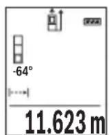
Co KpaTko npHTNcKaHe Ha MEPHOTo KOJIe (2) [Aro npeKnHyBaTe KOHTHynpaHOTo MepeHe. AKTyEnHaTa H3MepeHa BpeIHOCT Ke ce npKkaKe Dony Ha ekpaHOT. Co NOBTOpHO npHTNcKaHe Ha MEPHOTo KOJIe (2) [AKOHTHynpaHOTo MepeHe OJHOBO CTapTyBa.
KoHTHnHynpaHToMepeHe aBtOMaTcKn ce ncknyBa no 5 min.
MepeheHaNoBpshHH
H36epeTe MepeHe Ha noBpHHn
Ha KpaJ, n3MepeTe ja shnHnHaTn DOJxHnHaTa eHNO NO pyro KaK MepeHeTo Ha DoJxHH. Nomey DBeTe MepeBa, nacepcknot 3paK ocTaHyBa BklyueH. Tpacata WTO Tpe6a Da ce n3Mepn TpeNka Ha npKa3OT 3a NobpshnHcKO MepeBe
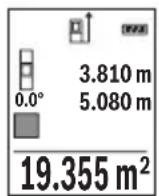
IpbBaTaN3MepeHa BpeHocTe Ke ce npKaeKe rope Ha ekpaHot.
No 3aBpUyBaHe Ha BTOPO To MepeHe NOBpUHHata ABtOMaTcKn Ke Ce
npecMeTa N npKaeKe. KpajHnot pe3yUItat CTOn dOly Ha ekpaHot, a
noeINHeuHnte N3MepeHn BpeHocTn Hd Hero.
Mepehe ha Bonymeh
H36peTe HnDnpeKTHo MepeHe Ha BnCnHn
BHHMaBajTe Ha Toa, MepHnot ypeI da e Ha HCTa BnCnHa KaKo N DOJHATA MePHa TOUka. IToTa HABanete rO MepHnot ypeI OKony pepepeHTHO TnBO N 3MepeTe ja Tpacata KaKo Kaj MepHe Ha DoJIHHata ,1" (Ha ekpaHOT e pnpKaKaHa KaKo CpBeHa JINHJa).
358|MaKeDoHcKn
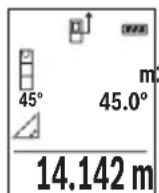
I0 3aBpUyBaHBe Ha MepeHbTo, Ke Ce npKkaxe pe3yNTaTOT 3a 6apHaTa TpacA ^ BO peoT co pe3yNTaT (e). IV3MepeHnTE BpeHocTN 3a Tpacata 1^* n aroNOT ,a CTOJAT BO peOBOHTe CO n3MepeHN BpeHocTN (d).
b)ДBoJHo HnDnpeKTHo MepeHBe Ha BnCnHa (BnDn CnKa C)
MepHnot ypeD moKe da rH n3Meprn dIpeKTHO cHTe TpaCn, KOHTo neKaT Ha BePTNKaJIHOTo HnBO Ha MEPHnot ypeD.
I36epTe IBOJHO INDnpeKTHO MEpeIbe Ha BnCHN
I3mepete nTpacnte,1"u,2"kaKo np MepeHe Na doJxHHn, no OoJ peOocne.
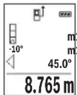
IIO 3aBpyBaHBe Ha MepeHbeto, Ke ce npKaepe3yNTaTOT 3a 6apaHaTa Tpaca ^ BO peDTo CO pe3yNTaT (e). N3MepeHnTe BpeHocTn 3a TpachTe 1^ ,2^ n aroJOT ,a" CTOjAT BO peoBnTe CO H3MepeHN BpeHocTn (d).
BHHMaBaJTe Ha Toa,pepepeHTHO HnBO Ha MepeIbeTo (Ha np. 3aHnOT pa6 Ha MEPnOT ypei) Da CTOn TOUHO Ha NCTOTO MecTO pnp CnTe
IIOeINHeuHMepeHa3aBpeMeHaMepHnOT IpoueC.
c) HnHpeKTHo MepeHe Ha doJnxHa (BmN cInka D)
H36peTe HnDnpeKTHo MepeHe Ha DOnJxHH
BnHmabajTe Ha Toa, MePHNOT ypeI da e Ha HCTa BucnHa KaKO n bapaHaTa MEPHa TOnka. Notoa HabaIeTo MepHnot ypeI OKOy pepepeHTHO TnBO n 3MepeTe ja Tpacata ,1" KAKO KAJ MepeHe Ha IOnxHATA.

IIO 3aBpUyBaHBe Ha MepeHbTo, Ke Ce npKkaxe pe3yNTaTOT 3a 6apHaTa TpacA ^ BO peoT co pe3yNTaT (e). IV3MepeHnTE BpeHocTN 3a Tpacata 1^1 n aroNt ,aCTOJA T BO peoOBHTe CO n3MepeHN BpeHocTN (d).
Mepehe Ha KocHH/AnrHtAlHa N6eNa
N36epete MepeHe Ha KocHH/ДИгТанHa N6eNa
MepHnOT ypea bTOMaTcN npeppna nomey duBe cocto6n.
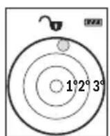
Дигталната Лбеба служи 3а поверка нахорзотално Ипьертукално Изразмунваъе на лениObject (Ha np. Maшина за посяve,фрждер nTH.).
ДOKOLKY се Ндмине КOCINHaТа 3°, TOnyeto Ha ekpaHOT CBTeNцрBEHO.
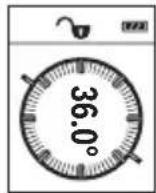
MepebeTo Ha KocHH CnyxH 3a MepeBe Ha HarOpHNuHaNoHn (Ha np. Ha cKaH, reneHepn, pnp BkIOnyBaHe Ha Me6eI, pnp IIOJoxyBaHe Ha ueBKn nTH.).
Kako pepehTHO HnBO Ha MepebeTo Ha KocHH CnyxN NeBaTa CTpaHa Ha MEPHnot ypeI. IOKOLky PpHKa3OT TpeKNa 3a Bpeme Ha MEPHnot npoec, MEPHnot ypeI bnil pemHory HabaleH Ha CTpaHa.
Функцн Ha MemopnaTa
BpeHnOCTa Ond. KpaJHnot pe3yIITat Ha ceKoe 3aBpIeHO MepeIbe aBTOMaTcKn Ke ce 3aUyBa.
PnkaHa 3auyBaHaTa BpeHocT
ДOKOLKY BO MEMOPNJATA HEMA PACNOLOXINBA BpeHOCT,ДONY HA ekpaHOT Ke ce npikaxe ,0.000", a rope ,0".
HajctapaBpeHocCT ce HaoraHa no3nju1 BO Memopjata, a HajHObTa BpeHocT Ha no3nju20 (o2 20 paCnoJIOXnIBn MemOpnpaHn BpeHocT).PpN 3aUByBaHe Ha BpeHocT cekoraw Ce bpiue HajctapaBpeHocT BO Memopjata.
Бршени на меморида
3a 6pniuehe Ha coDpxHHata Ha MemOpjata pntHcHe Ta KOnueTo 3a MemOpnpaHe
(6) []. Пота Кратук Рпинсные Н konчето 3a Влуваье-нckлuyыьe (5) [], 3aда ѳизбришete ппікжанATA BpeДноCT.
3a 6pnuebe Ha CHTe BpeHOCTH KOI CE BO MemOpjata pINTCHETe HN HCTOBpeMeHO KOnyeTo (4) n KOnyeTo 3a BKnyuBaBe-NCKnyuBaBe (5) [Φ] n Notoa OTnyuTeTe rO KOnyeTo 3a BKnyuBaBe-NCKnyuBaBe (5) [Φ
Cobpahe/oidemaheHaBpeHocTn
I3MepeHHTe BpeHocTH IN KpaJHTe pe3yNTaTH MOKe Da ce co6npaat nn Ondemaat.
He ro notonyBajTe MepHnot ypeD BO BODa Hn Dpyr TeuHocTn.
I36pniuTe rH HeunCTOTnITe CO BnaJHa MeKa Kpna. He KopncTeTe cpeiCTBa 3a uHcTeHe Hnn pactBOpH.
Ocobeno odpxybaje ja uHCTa npemhata neka (14) co nctata rpnka, co koja Tpeba da ce odpxybaat ouHnata nn nekata Ha foToanapat.
Bo cnyuj ha depekt nnn nonpaBka odheceTe ro mepHnot ypeD BO OBnacteHa cepBncha cnjxba ha Bosch.
CepBncha cnjx6a n coBeten npn KopncTeHe
CepBnchata cnjx6a Ke odroBOpn Ha BaunTe npaaBa Bo Bpcka Co nonpaBkata n OdpKyBaHbeto Ha BaHOT npo3BOD kaKo H pe3epBnTe DeNoB. O3NaKn 3a ekCnno3naJ HnHopMaun 3a pe3epBnTe DeNoBn NcTo Taka Ke HajDeTe Ha: www.bosch-pt.com
TMMOT 3a COBeTyBaIbe npn KOpIcTeIbe Ha Bosch Ke Bn NOMOrHe JOKOJIky HMaTe npaIbHa 3a NaIHTe IpOnI3BODn n OnpeMa.
3a cTe npaaHa n HapaKn Ha pe3epBn DeIOBn, Be monme habeTe ro 10- cnppenot 6poj od CneuNkauHata nnouka Ha npOn3BODot.
MaKeDoHnJa
Д.Д.Енковс
CabaKobaueBnK 47H,6poj3
1000 Ckonje
E-nouta: dimce.dimcv@servis-bosch.mk
HHTephet: www.servis-bosch.mk
Ten./daKc:02/2467610
Mo6.:070595888
Д.П.T.Y“POJKA"
JAHN LyKPOBcK 66;T.LA BTOKOMaHaJa loKaI 69
1000 Ckonje
E-nowta: servisrojka@yahoo.com
TeN: +389 2 3174-303
Mo6: +389 70 388-520, -530
OtctpaHyBaHe
MepHnTe ypei, onpemata n am6aJaxnTe Tpe6a da ce otctpaHaT Ha eKoIooKn npdaTnB HauHH.
He rH pRnajTe MepHnTe ypeN n batepHnTe BO DOMaunHaTa KaHTa 3a otnao!
Cama 3a 3emjnte oEY:
CnopeEeBpOcKaTAnpeKtNa 2012/19/EUMepHnTe ypeN ITO CE BOH ynoTppeBa NdePekHTHe HIN NCKOpNCteHnTe 6aTePN CnopeI DnepeKTHBaTa 2006/66/EC Mopa OndenHO da ce cobepa T da ce peuNKnpaat 3a NOBTopHa ynoTppeBa.
Srpski
prikazuje,0.000", a gore,0".
Do not stare into beam.
Class 2 laser product
Ce besedilo na varnostni nalepki ni v vašem jeziku, ga pred prvim zagonom prelepite s prilozeno nalepko v ustreznem jeziku.
Akumulatorske celice 2 x 1,2 V HR03 (AAA)
Aku-celije 2 x 1,2 V HR03 (AAA)
A) Kod mjerenja pocevsi od prednjeg ruba mjernog alata, vrijedi za visoki stupanj refleksije ciljne povrsine (npr. bijelo oličeni zid), slabo pozadinski svjetlo i 25 °C radne temperature. Dodatno se moze raćunati odstupanjem od ± 0,05 mm/m.
B) Kod mjerenja pocevsi od straznjeg ruba mjernog alata, vrijedi za niski stupanj refleksije ciljne povrsine (npr. tamno oliceni zid), jako Pozadinski svjetlo i - 10^ do +45^ radne temperature. Dodatno se moze raucunati s odstupanjem od ± 0,15mm / m
C) Nakon bazdarenja korisnika kod 0^ i 90^ treba uzeti u obzir dodatnu grešku uspona od ± 0,01^/ stupna do 45^ (maks.). Kao referentna ravnina za mjerenje nagiba služi lijeva strana mjernog alata.
D) Pri radnoj temperaturi 25^
E) Kao referenta ravnina za mjerenje nagiba služi lijeva strana mjernog alata.
F) U fungciji trajnog mjerenja je maks. radna temperatura +40^ .
G) Dolazi do samo nevodljivog onecijscenja pri cemu se povremeno ocekuje prolazna vodljivost uzrokovana orosenjem.
H) Osim pretinca za baterije
Laser Radiation Do not stare into beam Class 2 laser product
Darbs ar stativu (papildiederums)
Stativs ir ipasi noderigs, veicot merijumus liela attaluma. Novietojet merinstrumentu uz stativa atri nomainamas plaksnes ta, lai ta 1/4" vitne (13) atrastos pret stativa (18) vai tirdznieciba pieejama fotostativa stiprino so skruvi. Ar stiprino so skruvi stingri nostipriniet atri nomainamo plaksni uz stativa.
Nospiezot nules limena izveles tausti (4) izvelieties atbilstošu nules limeni (no vitnes visus).
Klumes zinojums
Laser Radiation Do not stare into beam Class 2 laser product
山p,山
gJgJgJgJgJgJgJgJgJgJgJgJgJgJgJgJgJgJgJgJgJgJgJgJgJgJgJgJgJgJgJgJgJgJgJgJgJgJgJgJgJgJgJgJgJgJgJgJgJgJg
Jgagglgaggglglll
JjIg
4g gglc
4.juUjgeG
p JjUll a g oJb1i .aglg oJbIs jUll a g oJbI p Jss W JJJl E Lw! no y 8 [j] JfJ JJJL
A. uuuu u u
Jlai I aaiuui 1 gg aai Jn aoaiiaa Jjll aag jal .Jglj Jua
oo uo o uo
.1JlJIbBpIaIcJlaiaIc aIe
. wI J I oJ uIol
180^
aag jgs wlaow
- aIj o juU
aJgG 5JJ
.1J 111 111 111 111 111 111 11
.0j2g ojc2oJwJwJl
sIg aaiJl aog
aagao lksg wull oogwj gajll aalall
.1JooawJäawJ6 oJ
Jusai JusuW
Ig Ig bIg JgJg Jg Jg Jg Jg Jg Jg Jg Jg Jg Jg Jg Jg Jg Jg Jg Jg Jg Jg Jg Jg Jg Jg Jg Jg Jg Jg Jg Jg Jg Jg Jg Jg Jg Jg Jg Jg Jg
g 1wJ 1wag g
Jg JdU 1uW U ual o
jgaal |jX
a a o gagall wlll oogw j l gaaal 1jJ i
.ubuulgomega
aLw (1)
1
[+] dlj jll (3)
JJISSGIMAIJJ>JJ (4)
[0]clabVgJzWlljj (5)
[0] 1 (6)
[Func] 100
[-] 0jll (8)
(9)
(10)
JulwuaJU 11)
UJyjzaiy (12)
aog 1/4 jJolj JgJ (13)
awsc Jl(14)NJ
= 1.5
(A)
0g(616)jU
(A
aUbua0
(A)
Jol
gul l gglgul gglgul gul gul 2 (A
gU liou 1 oLJI
(juaI yua) jull polic
L
sguio slw(h)wl
aJb(c)
wllp
aaiill (e)
(f)
JaJIgj (g)
(h)
aaiilulll
GLM 500
jjuUyJlJU JUJU jL
3601K72H..
aiall
aogpOg:p
wll 0g bio
0,05-50
()
B 20
(a)wlojgj>gaj)wllg
(A)oo ±1,5
(≥gai)wlaall
(B) a ± 3, 0
(aωwlio,εδgjb,a>gai) wlaall a9
0,5
( 0,12,0,12)
(4× 90^)360^ - 0^
Jzogwloge Jswdll
J 1
(4× 90^)360^ - 0^
J
D(E) ±0,2°
J
(≥)wlaai
454
.1J 1 J 1 J 1 J 1 J 1 J 1 J 1 J 1 J 1 J 1 J 1 J 1 J 1 J 1 J 1 J 1 J 1 J 1 J 1 J 1
.40+ 1jai jai jai jai jai jai jai jai jai g (F
g g 1111111111111111111111111111
aiagoojgauLJgU Jgogawil
aJbUJI oJua liuU (H
.11 (11) JuswaiIJI JgJrJgJgJgJgJgJgJgJg
#
J 1 J 1 J 1 J 1 J 1 J 1 J 1 J 1 J 1 J 1 J 1 J 1 J 1 J 1 J 1 J 1 J 1 J 1 J 1 J 1 J 1 J 1 J 1 J 1 J 1 J 1 J 1 J 1 J 1 J 1 J 1 J 1 J 1 J 1 J
4.15 15 Lgga
(463 aJ,(E2-E1 Jj)
Lg
(2) wlaJIJJIg aagaaagglgJUILg wlaJI Isc Jw- [A] 1JSSWll JJIg aagaaagglgJUgJUgJUgJUgJUgJUgJUgJUgJUgJUgJUgJUgJUgJUgJUgJUgJUgJUgJUgJUgJUgJUgJUgJUgJUgJUgJUgJUgJUgJUg
JU 1 JI Uaagg g Uulgglg JjUu Ieaw aagg .JbK JUU Ew .Lbgao [0]5)labg Uusuill jbuai Iuauo sLab! JrJd. abgo jlgblbgsloagaiuallpuiuoiuuaiauc
wlaJI aLac
aBg .Ugblwlaagabg g wuall oocngkssll s
yglall wuall aagbgsd. [Func] (7) jll lgl, yI , wuq "wuuuug, jilj) no [-] (8) allooll [+] (3) alloall pdoasswu g [Func] (7) 1o oolwlu wuauagg (458 aoull .[A] (2) wuulg
. wll jy S wll 0d aal l al al p y ll jy wll . "A oJgall jbl) jolll gswll Jj, jbl), jolll gswll jj 1457.
.(bJll Jlal JIw (c) agejol wJall y abai Ic wJall osc bJol [0]5) 1g Jssill j go wJoll oSc Jssaw p|J:J
wlaJI alao lc ojag ojai)2().jjll JssuJl [
A wll uall jj c oag dlgl bai)2(1w sab] pui L .jai w q i d aiaa aiaa 0 Js. jull
UJjbi d4g
. jS 8j 2g jll E
4 0,5 1 aai all g aaal aai j: s w!
w laoaog o aagg aalllc waaal do g g. jk
logg jjull eaw labp y wlaall qil sb .gdll abio
JgJl) JJI JAA(A
wlljj(b).wlll lwlal wlllaa jbjjwnall wlll 12] (2) wllll jj ldsno bll sic .Jy Jn no Jnnall .logggl 5 5 Jnwwll wlll ggy
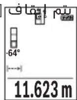
LwJ
□
g.1g2l wq g loL lUu UgBllg uaoa q, 1s Lw q slal aIluu Iooj .uau I yloc n JyJzIu Ie
.aaUulUclUwUgdoog UgI jebj
Igai Iaia Iaa aai iil Ilaal Iqul Jllg oJg Jai Iagai JpJ .
LggeooLcUsawlaoll
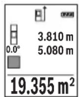
pLgJ Lg
□pIulwlaJ.
.1g21 w g 1s Lg2111 g 1g2111 g 1g2111 g 1g2111 g 1g2111 g 1g2111 g 1g2111 g 1g2111 g 1g2111 g 1g2111 g 1g2111 g 1g2111 g 1g2111 g 1g21
□pI 1wUg UyUgUgJrJI.
.aaI I JwIg qag JgJpJ 1000000000000000000000000000000000000000000000000000000000
Lg9gdd
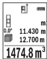
wJgKshd
Lgio JSGwog,swjo jE JkWbJl wlaJwag Jg
.adolio Uelwos wlu
LgwsyKsJxI yIyIyIyIyIyIyIyIyIyIyIyIyIyIyIyIyIyIyIyIyIyIyIyIyIyIyIyIyIy
LwJU 10gWgOJl
:JdUJUaJoo a
Ljui juii iuiuui uuiuui uuiuui uuiuui uuiuui uuiuui uuiuui uuiuui uuiuui uuiuui uuiuui uuiuui uuiuui uuiuui uuiuui uuiuui uuiuui uuiuui uuiuui uuiuui uuiuui uuiuui uuiuui uuiuui uuiuui uuiuui
.(g|g)
.aaJolUwIollUlcac JjUeWllJgJJUeIeW
a ojgJJI jai) Ucl
claojJwIaJI Jc WlaJI Jai.
aJawll wIall abai eia jui gic wIall oocg gic uol aIg Iwll wIq gog yjll igwll Ugs wIall oocg
.(aasaaawwllg)UgbllwlaicJalIgws
Lulai Jlall aIwll dji jbi jwIol Iqil "X" ^ agjllg1"1" aIwll wIoll pqi jbi.(e) aii lps
uul aJgaw d
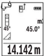
b ojgall jbil) lc
wJllgssall g 11111111111111111
. JEJKswWUaIoo
UcIaJU WlloU JgJoU WlaJI
.1"2"g"1" 11111111
LwaiJlJal aIwJai jbj, wIaI Iqil 1y JglJg "2","1" aIwJAL WJAI Jj. (e) auiI Jbw
.(d) 1w lI I gBw
aJlJI JIJI JIJI (Jc) wJal lJy jgWJALJ 1dS J IJgJgall wJn JbJbJ (wJALOJ aJALJ
wJdAolac jaoa JdJI wJdJI
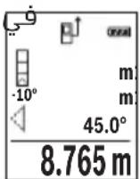
D(ogaljbl) Ugbluoll uolll (c
UgbljwlaJmuCwlaI
aaii iil wlaal abo j elojj mai j icwlaal osc gag lcl
wulg g yjll gswll lgs wll osc lgl, s
.ugbJI wIgSic JUJI gLoS "1" aJluJI
LwaiJlAaIawll aagjub,wwlaIguiI"X" "aigj1g 1" aIwauI wiaI pq jab.(e) auiI Jw
.d) wLlI a 1gbaW
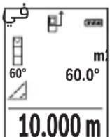
JJI lJI Jj/ll JJI
- 1
.1uIla uIyloggI wUaIooJai
wJg|gjgW| jyjlll jpo g. (aLw log aJLl, JluuJ, JUauJJ) uJ LJ.
JUuJ UJUJ UJUJ UJUJ

Jg Jg Jg Jg Jg Jg
UgBg jSicg jjJJlg pJLwJy aolllllo)
.(duwlogjuwlgajxog
0e 1
Jg, wIaJI aIoc -wI gOy yogol I y J. wIaJI
. wJJI gai wJAI Isc Jauo o slj pa ai
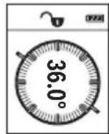
jS1JJ aJb9
puiu q aloc uL q aIgai giaaai jn jLlogig
Lgio LgjX1
aijajaiaijju
LcSsiJSSa20.GagS (aJU
bαu|jj(bcαδ)6().[
g aaiiaaaii 1
wJll aobg jwll lc jbj loL qaiolil ajaoi aoJI
Lg aol
.lscai abgaoJl pui jaoi [+] (3)jjI Lc b
.1jliabgsaalI paiI gai- jllgbeol
J 1
."0" aaiJ1 LwLcIg
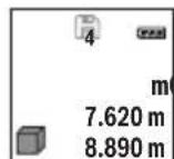
430.16 m³
20gagall g aeg dal dgig oJl J1 gagll gao
pJgao laIpaia aai jaj sic.(ogagall ajjal 20 paiJI g)
.0J1JJ a
jsljj 2w
Lc oJaua aIgJ bauai J. [6] (6) koull JJ Lc bauoi oJl jll gao gao
.aaogjaoIgol [0]5)labg j
jjg (4) jll lcc gll sai j bdoi oj Jl Jbgaal p q
. [出 ] 5)labgJuswuljjjul [0]5labgJuswul
a/20
.1g 111111111111111
pJ 20
:Jlalj
“lalwll wlg,jbjil)《laowll wlg》jJ LdaLwllUwsl
.(458 a
."+jogd aaiolll alwoll jgbl p.[+] (3)jjl lcb
1000
b0°+93.406 m²
(aai)jquiJ
143.45 m²
aalwau auiWl wluai aulac aui jla b! pui aui
jjLc|ssoo bai,ajlgjll aayil jqby.1jowl jaoawlJl
UuJI1)2().[
.1gblwglgllgollllglb|p:slj
.Func jJI Lc bdoJl aoojol
e 1
gogal afo 1001001.[-]8)jjI c bdo,po
. a1 + a2 + a_3 = 6
WJI 2
g0labg jjgc aag algl bgl lda n no s aag gl bgl n no k. uuall agg Uc g u
j j w l q g [0]5)labg JJJJ Sio J
LmuSc
wIaI Ig J
.()"m"wUaJIddg g wWwJbuaJg
UuOJIOsc Uoo
. 一 ~ d ~ l ~ o ~ 工 工 工 工 工 工 工 工 工 工 工 工 工 工 工 工 工 工 工 工 工
(jio / a) "ft/m,"jai
dd [0]5)1g jj 1aJd
.1bgoJlaiJI buiJI gog JbiI
Ug/
wIbIg g
UwJooI ooc uoo
. 一 _ 一 ^ 一 wIbUJIg] aJI UgogU,Upg [Func] (7) jIy Ia
.ugJl g Jjw[-]8)jjg[+]3)jjLcbso| jai
(5) 口 b 口 g 口 口 口 口 口 口 口 口 口 口 口 口 口 口 口 口 口 口 口 口 日 日 日 日 日 日 日 日 日 日 日
.1gao jiaolll buiolll gog u yuolll ooc
JlI 1sJ!
dole U
.(15)jJUAAaJg(14)JuaawAawscabzjgjx
GgJcJyIbWlJg.JuJIaLacwIwJALOeJyJgJx
. JkJbawgJaaawJcWJALo
wIJIJIJIOIc oJgO Jolgc
aobiaol wksjI Iwlaog oLxg jgpoIc wlaal gIbJ aagg 0yduuI yIaI IooI aIa JJJUeIaI uI aJgJ aJILSO. dglg (g|gll) (16) JJUU bIygJg (g|gll) (17) JJUU aJgJ oJbI pSaaI .dJII abio plicy
wlaaiiauiIc oJgolgc
wiaaaijyilwaii wai iie aibla iawg jwwn kys 1qioo no .adilo so gbw
J 1 J 1 J 1 J 1 J 1 J 1 J 1 J 1 J 1 J 1 J 1 J 1 J 1 J 1 J 1 J 1 J 1 J 1 J 1 J 1 J 1 J 1 J 1 J 1 J 1 J 1 J 1 J 1 J 1 J 1 J 1 J 1 J 1 J 1 J
slluag aq sdo u
:UwL wuai oac aJ uag liS
- 1gj
wJl. (Uaag, aJg Uaal JwLc) dduy 2000 aJg wJall aJLw gK jI yBn Jg LwLio gJg Lg WJALI gJd Jg Jn Jg Ls Kaae eae ae ae ae ae ae ae ae ae ae ae ae ae ae ae ae ae ae ae ae ae ae ae ae ae ae ae ae ae ae ae ae ae ae ae ae ae ae ae ae ae ae ae ae ae ae ae ae ae ae ae ae ae ae ae ae ae ae ae ae ae ae ae ae ae ae ae ae ae ae ae ae ae ae ae ae ae ae ae ae ae ae ae ae ae aa
- aJluaJUwLpa
g .pIgll llll pI sIwI I kI bI I I I I I I I I I I I
oJcK aI I J 1 J 1 J 1 J 1 J 1 J 1 J 1 J 1 J 1 J 1 J 1 J 1 J 1 J 1 J 1 J 1 J 1 J 1 J 1
.
iJgS

Do not stare into beam
Class 2 laser product

Jusu y 15g j J gS uj a oLsw soljau
.
g 8
L daiw jgj,1j91 5saw o a jnio cwi Jkao digsi
.

.
$$ \left. \right.\left. \right.\left.\left.\left.\left.\left.\left.\left.\left.\left.\left.\left.\left.\left.\left.\left.\left.\left.\left.\left.\left.\left.\left.\left.\left.\left.\left.\left.\left.\left.\left.\left.\left.\right.\right.\right.\right.\right.\right.\right.\right.\right.\right.\right.\right.\right.\right.\right.\right.\right.\right.\right.\right.\right.\right.\right.\right.\right.\right.\right.\right.\right.\right.\right.\right. $$
$$ a _ {i} l _ {i} a w ^ {\prime \prime} 1 / 4 o g j \tag {13} $$
$$ \therefore \omega_ {2} c = (1, 4) $$
$$ \geq 9 \div 9 = (1. 5) $$
$$ (a) \quad a = 2 a + a \cdot 9 (1 6) j, $$
$$ \begin{array}{l l} \text {(A)} & \text {S i n c j j (1 7)} \end{array} $$
(A)
$$ a \omega a \cup (1 8) $$
oljgogjgbj,0sol jooLguguJdSjlaleo dL (A 1olj Cwq9 jI JcIalteo Jols CwU IabJ. gW Gai dljl oLsw S.Jlai wJlclao
$$ (\varphi \text {l a i l}) j \hat {\omega} \omega \text {l o a j} \text {l g} \text {i a w} $$
$$ w l > w l a $$
(a)
$$ S _ {1} S _ {2} O j l \downarrow i g e > r o c b a w (b) $$
$$ \mathrm {s i g m a} _ {i} $$
cI
$$ \left. \right.\left[ \circ \circ j \right] \circ \left. \right.\left. \right.\left. \right.\left. \right.\left. \right.\left. \right.\left. \right.\left. \right.\left. \right.\left. \right.\left. \right.\left. \right.\left. \right.\left. \right.\left. \right.\left. \right.\left. \right.\left. \right.\left. \right.\left. \right.\left. \right.\left. \right.\left. \right.\left. \right.\left. \right.\left. \right.\left. \right.\left. \right.\left. \right.\left. \right.\left. \right.\left. \right.\left. \right.\left. \right. ① \circ j _ {2} w ^ {\prime} \circ j _ {3} w ^ {\prime} \circ j _ {4} w ^ {\prime} \circ j _ {5} w ^ {\prime} \circ j _ {6} w ^ {\prime} \circ j _ {7} w ^ {\prime} \circ j _ {8} w ^ {\prime} \circ j _ {9} w ^ {\prime} \circ j _ {10} w ^ {\prime} \circ j _ {11} w ^ {\prime} \circ j _ {12} w ^ {\prime} \circ j _ {13} w ^ {\prime} \circ j _ {14} w ^ {\prime} \circ j _ {15} w ^ {\prime} \circ j _ {16} w ^ {\prime} \circ j _ {17} w ^ {\prime} \circ j _ {18} w ^ {\prime} \circ j _ {19} w ^ {\prime} \circ j _ {20} w ^ {\prime} \circ j _ {21} w ^ {\prime} \circ j _ {22} w ^ {\prime} \circ j _ {23} w ^ {\prime} \circ j _ {24} w ^ {\prime} \circ j _ {25} w ^ {\prime} \circ j _ {26} w ^ {\prime} \circ j _ {27} w ^ {\prime} \circ j _ {28} w ^ {\prime} \circ j _ {29} w ^ {\prime} \circ j _ {30} w ^ {\prime} \circ j _ {31} w ^ {\prime} \circ j _ {32} w ^ {\prime} \circ j _ {33} w ^ {\prime} \circ j _ {34} w ^ {\prime} \circ j _ {35} w ^ {\prime} \circ j _ {36} w ^ {\prime} \circ j _ {37} w ^ {\prime} \circ j _ {38} w ^ {\prime} \circ j _ {39} w ^ {\prime} \circ j _ {40} w ^ {\prime} \circ j _ {41} w ^ {\prime} \circ j _ {42} w ^ {\prime} \circ j _ {43} w ^ {\prime} \circ j _ {44} w ^ {\prime} \circ j _ {45} w ^ {\prime} \circ j _ {46} w ^ {\prime} \circ j _ {47} w ^ {\prime} \circ j _ {48} w ^ {\prime} \circ j _ {49} w ^ {\prime} \circ j _ {50} w ^ {\prime} \circ j _ {51} w ^ {\prime} \circ j _ {52} w ^ {\prime} \circ j _ {53} w ^ {\prime} \circ j _ {54} w ^ {\prime} \circ j _ {55} w ^ {\prime} \circ j _ {56} $$
$$ S _ {j} S _ {i} o j d i l a > \dots j S _ {i} w _ {i} L a j b w \tag {e} $$
$$ S _ {i j} S _ {j i} o j 2 i l S _ {i a c} \tag {f} $$
$$ \omega_ {a} g _ {j} \bar {S} _ {i} l a _ {i} \tag {g} $$
$$ \ddot {L} a b \ddot {b} \quad (h) $$
i
jul liu jao
GLM 500
| 3601 K72 H.. | السلام |
| الbvrl.(ft) بعه,(m) JB (in) | سورعال مبانيماتي |
| (A) JB 50-0,05 | (عربية) سورعالسورعالسورعالسورعالسورعالسورعالسورعالسورعالسورعالسورعالسورعالسورعالسورعالسورعالسورعالسورعالسورعالسورعالسورعالسورعالسورعالسورعالسورعالسورعالسورعالسورعالsurd |
| (B)20m | (عربية) سورعالسورعالسورعالسورعالسورعالسورعالسورعالسورعالسورعالسورعالسورعالسورعالسورعالsurd |
| (A) JB 50±1,5 | (عربية) سورعالسورعالسورعالسورعالسورعالسورعالسورعالسورعالسورعالسورعالسورعالسورعالsurd |
| (B)±3,0m | (عربية) سورعالسورعالسورعالسورعالسورعالسورعالسورعالسورعالsurd |
| JB 50±0,5 | (عربية) سورعالسورعالسورعالسورعالسورعالسورعالسورعالsurd |
| السلام | |
| (4x90°) 360°-0° | سورعالسورعالسورعالسورعالسورعالsurd |
472|
(1gJ (5gJ)0) oJdSjSjOjI jEgJw S daai (5gJ I J SsOjI jJI
.
oawj [0] jwajogola daS J gJoljljla:diSi(5)
.1JjJ jS jg j [A] (2) 0j si oos oig S,
. 山 山 1j[▲] (2) (20 s oJdil sdoS oUgS, sOoJdil g
.1jSjI jdaJooJ JsOjJil sJgW Go wgoJjUw
J 1 J 1 J 1 J 1 J 1 J 1 J 1 J 1 J 1
.8gW Go oJ uW j 52u

aWg u 5u oJdJl
aJgJlJjI jJjI cJ Saa oJsl J
j0s jol jdo o g o jd s g w 0,5o d
gis alolg jolgJgL golalg l jlgj jglglo
. 10 uJgA UgOJlgao
aewg jj ojl.ajl l
Sj0jdl (sdoJ jJ jg jJ gJ 2(1 Jw oJg S
.
a aai j jbi jgo dlol dsi i u s y b s jd oj j slj jj
.5g0s1jluu jdua dauo u
Saa ojol [A] (2)Ss ojl aosolg
jga daa o j uu ly gigi s 5u ojl sl Jdo .si s pai
26j oJsi dss jug s Jsaw .gwoi
. 日 ≤slant 日 ≤slant 日 日 日 日 日 日 日 日 日 日 [▲]
GgoljSgajgbdaag5jlJxoo
.
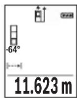
ω|477
abw 0jsl
oJsiI JgB gS oJsiI SiI aW w W y I g Lai jg B, jc uu w
Jua. sio 10 10 10 10 10 10 10 10 10 10 10 10 10 10 10 10 10 10 10 10 10 10 10 10 10 10 10
.0000000000000000000000000000000000000000000000000000000000000000
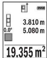
pss ojlil pss ojlil. jll
ojsl jgbsjol sioo w w w y I ggb, jc w w w w .silo o l jw gj ojl si d w n dlal j jg jy.
:oo ju wj jagbwg ju J
Sj ojl, d j Sj EgJ) "baw s j ojl, j w l, J baw S
.1sS aWb7(ao,“abw
c0lc g o w dawlao baw. jluw [+] (3) aos
.1gwh0001Jlwh+
Sj ojl sll jwJl w (2) 0jxl d
ojj, uw wluI Jabw S. dEgJw I jSbaw
477(dao,“2bw 5u ojl jil,du uis Egaj)“2bw U
ojsl dui jolj l jw poai a. uu
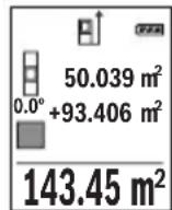
duuui uuiuuiugg. gwh oosn uuiuugd aao nuy jcbw
. 1j [A] (2) Sj ojl si dos o jg g, Lj
.001jw jg gJe dww, jgb oJdjl pLsi:aiSi
.duj Func dsJ egaoo jS Sji
oi jslj jSj
g a l w o loI dJ yIw .d J Iu g [-]8) 0oS L OjI jil
.
.1J [Func] (7) 0s "UJ UJ J" CwJg D j
f t / m^ .uS uI
j 0j jil g li ju w Jlu []-8) dS J [+] (3) dS
.
0 - doS s wjq SJJ 5(] wgoia j W
.0gwho ooho oohw faii lalabu .jsl jj1n
1s jS g
.1Jg(j)|,dggllaabjj
.5iS jwgljg ojljlj
.1JgSj o s w [Func] (7) aos "Lullalaa" cws g y j
jLwJUogUgBgUgIJ[-](8)aosu[+](3)aosu.uaS UaiI J
.
1j [0] (5) 1og g bgaosu [A2] sO jsl daS, Cwq
o w u laai l oaiu oj ul jul u w gol j u w.
gogoo
Lac lai
g
jol jol kio (15) jjg g (14) o sijd jil
.
159j 15u ojl jil jlg jil .Jg jn Jl Sio u j 0jsl jj
.
Sj 0jI sI oJgdoo Js oJl jI jI jI jolgc
a 000 000 000 000 000 000 000 000
Sicjg jgogg pio jui gji jie sI i
abw L sis o slawl (Laloo) (16) JJd ddo g (Laloo) (17) JJ
.1j1suiuulwIj
Sj 0jsl aai j s o jl ljulg c
ojjol pIiawd s g jiaabo jlgj gSjgolga gJolgc JUs
diwi gag 5j ojl j Lbdaig aolao gbw (gj J S
(aj) paaa a jgb as gka w j s oj sla j oglc
.100000000000000000000000000000000000000
poojue jol lglg glglaio slloo ly gao caldo yu
. 1j j j j j j j j j j j j j j j j j j j j j j j j j j j j j j j j j j j j j j j j j j j
jglai duiS e9aj) uwh ojlal pabu g cJSE1-E2(
j0j j j j j j j j j j j j j j j j j
jJg jO SgJ Jg 0jJl JjI Jg bio oBwJy Jx Jx Jx Jx
15 ojl jI jSj 0jI jI jI .sIs 0jI jI juW g s180°
yj ooh jn jw jdo ool . yj jil juug g jia
j10,3. 山 山 山
. 1
CAL jgbio jyj yj lai 15g
.
Jus Jus Pss 1sglj jg lo s oJj jS J S OjJl Jj
ojj jjI iuLy loJ uJ jU y.duo J jU jU g
. jolos Jslj slj UgUgUgUgUg
cIwOgJdJgJiS
:uiuuiu j uugjdu JgJ 0jxljlglglo la
Lol s lui ly qil uba 10 3 ju jy Lg jc slqigluo
Lj. ojl .sij .uai | j (j u gjla ,gui jrc sila) cwi
jdy 5g ojl jgo cglwlo gplj wliobj
SjLdJlJlJrJrJrJrJrJrJrJrJrJrJrJrJrJr
:glj dslalgac slgws b
g doli i n ji i j k l o sl aai w l j g aq k s yjdl j l ay j l j l j l j l j l j l j l j l j l j l j l j l j l j l j l j l j l j l j l j l j l j l j l j l j l j l j l j l j l j l j l j l j l j l j l j l j l j l j l j l j l j l j l j l j l j l j l j l j l j l j


- GLM 500 Professional
- BOSCH
- 28|English
- Product Description and Specifications
- Intended Use
- Product features
- Display elements (selection)
- Technical data
- Digital laser measure GLM 500
- | English
- Assembly
- Inserting/changing the batteries
- | English
- Operation
- Start-Up
- Switching on/off
- Measuring process
- Selecting the reference level (see figure A)
- Basic settings menu
- Display illumination
- Measuring functions
- Measuring length
- | English
- Continuous measurement
- Area measurement
- Volume measurement
- Indirect distance measurement
- a) Indirect height measurement (see figure B)
- b) Double indirect height measurement (see figure C)
- | English
- c) Indirect length measurement (see figure D)
- Grade measurement/digital spirit level
- Memory functions
- Memory value display
- Deleting the memory
- Adding/subtracting values
- Adding values
- Subtracting values
- | English
- Deleting measured values
- Changing the unit of measurement
- Switching sound on/off
- Practical advice
- General advice
- Influences on the measuring range
- Influences on the measurement result
- Checking accuracy and calibrating the inclination measurement (see figures E1-E2)
- Accuracy check of the distance measurement
- Working with the tripod (accessory)
- | English
- Error message
- Maintenance and Servicing
- Maintenance and Cleaning
- After-sales service and advice on using products
- Great Britain
- Ireland
- Australia, New Zealand and Pacific Islands
- Republic of South Africa
- Customer service
- Gauteng - BSC Service Centre
- | English
- KZN - BSC Service Centre
- Western Cape - BSC Service Centre
- Bosch Headquarters
- Disposal
- Only for EU countries:
- Français
- Bortskaffelse
- Avfallshantering
- | Norsk
- Emuon pertpon anooradewv
- 186|EAnvika
- Kpntepn npedeBbIX coCToHHN
- Tn n nepnounduhoctb Texnueckoro o6cnyxHBaHNA
- XpaHeHne
- TpaHcnoptnpoBka
- Yka3aHnnoTexHnke 6e30nacHOCTN
- 270|Pycckn
- Onncahne npodukta uycnyr
- PpHMeHeHne no Ha3HaueHnIO
- H3o6paXeHHbIe coCTaBHbIe yaCTn
- HdHKaTopb1(Bbl6op)
- 272|Pycckn
- C6opka
- BcTabka/3ameHa 6aTapeek
- Pa6ota c nHcTpymeHTOM
- BkIIOueHne 3NeKToHHcTpymeHTa
- BkIOueHne/BbIKIOueHne
- PpoeUpa n3MepeHH
- 276|Pycckn
- BbI6Op IIIOCKOCTN OTCuEta (cM. pnc. A)
- H3mepenne nlouaa
- H3mepeHne 06bema
- 278|Pycckn
- KocbeHHoe u3MepeHne pacctOHHa
- ΦaKTopbI, BnHryIOuIe Ha dHaNa3OHN H3MepeHHN
- ΦaKTopbI, BnHryIOuNe Ha pe3yNbTaT N3MepeHHA
- PpOBepKa TOnHocTn KAnN6pOBkApn H3MepeHHyrga HAKNoHa (cm. pnc. E1-E2)
- PpOBepka ToUHcTH N3MepeHHpaCCToHHN
- Pa60Ta co wTaTHBOM (pHnHa,dNexKHOCTb)
- Coo6eHne 6 oun6ke
- TexobnyxmbaHne n cepBnc
- 286|yKpaIHcbKa
- Ytlln3aun
- Tonbko dna ctpaH-uehoB EC:
- YkpaHcbka
- Bka3iBkn 3 Texhikn 6e3nekn
- Bn6ip 6a30Boi nlouHHn (nVB. Man. A)
- Henpme BmmpioBaHHBicTaHi
- a) Henpme Bmipobanha Bncotn (nB. man. B)
- b) NodinHe Hnprme BmipIOBAAHBAHCOTN (INB. Man. C)
- c) Henpme BmipioBaHHn DOBXHHN (Hb.MaI.D)
- 296|yKpaIHcbKa
- BmipioBaHH kyTIB haxnuy/uzdpobBuBatepna
- Функцnam'nti
- BidobpaXeHH36epExeHx 3NaueHb
- CThpahnBmicty nam'atI
- DoaBaHHB/BiHimaHH3HaueHb
- DdaBaan3aueHb
- 298|yKpaIHcbKa
- Bidhimannha 3NaueHb
- CTupaHnBvMipaHnx 3HaueHb
- 3mHaOHHnCiBnMipIOBaHHa
- YbIMKHeHHBumKHeHHa 3Byky
- Bka3iBkn 0do p6oTH
- 3araanbHi Bka3iBKN
- ΦaKTopn BnHbBy Ha diana3OH BmipIOBaHHa
- ΦaKtopn BnNBy Ha pe3ynbTaT BmipioBaHHA
- Ipebeipka toHocri ta kani6pyBaHHa nla BmipIOBaHHa KyTa Haxnny (nB. man.E1-E2)
- Ipebipka ToHocTi BmipobHHB iDtaHi
- 300|yKpaIHcbKa
- Po6ota 3i wTaTHBOM (npnnaD)
- Pobidomlenn npo nomnilkn
- Texhuihe 06cnyroByBaHHaicepBic
- Texhuihe 06cnyrobybaHH i ouHueHH
- Cepbic i koncynbtaqii 3 nHTaHb 3actocyBaHHA
- YkpaHa
- CaKtay
- TacbImanay
- Kayinci3ik HycKaynapbl
- Ohim xhe kyat cnaTamaCbl
- MaKcaTbI 6oBbIHua KOnDaHy
- KopcetinreH KypamdbI 6eKeTep
- Kepcetkiu 3nemHTeP (TaHaMaIbI)
- TexHnKaIbIK mJImeTtep
- CaHdbik naep kaawbIKtbk eJlweriwi GLM 500
- AkkymyIaTOPbIK3JIeMeHTTep 2x1,2BHR03(AAA)
- Mоntаждан
- Batapeaapdbicany/annactbipy
- Пайдалану
- Icke Kocy
- Kocy/ewipy
- Olnwey aici
- Heri3ri xa3bIKtbIKtbI TaHday (A cypeTIN KapaHbI3)
- "Heri3ri napametpnp" m3ipi
- Диспей карын.
- OIIwey cyHKcuaapbl
- ¥3biHdbikTbIeWey
- Y3dkci3 enuey
- Ayaanbl eonwey
- Koenni enwey
- KaHama KaWbIKTbIKbit Onwey
- a)KaHama 6nIKtikTeIeUey (B cypeTin KapaHbI3)
- b) Koc kahama 6niktikti oIwey (C cypetih kappaHb13)
- c)KaHama y3bIHdbIKTbI eNwey (D cypeTih kapaHbi3)
- Enicti enwey/cahdik dehrre
- CaKtayfynKcunnapbl
- CaKtanaFaH mH KepcetKiWi
- JaTbI eipy
- Mэндерді кocу/any
- Māndeρdi Kocy
- Məndepdi any
- Oltwey Hataxkepein koo
- OIIeM 6ipnirin aybictbipy
- IbIbIcTbIKocy/ewipy
- Painanany Hycaynapbi
- KannbHcyckaynbikTap
- Onwey aMaFbHa ocepnep
- Kədere xapaty
- Romana
- Tek KaHa EO enepi ywiH:
- Româna
- Instruţiuni de siguranta
- Yka3aHn8 3a cnryphnoct
- 334|BbIrapckn
- Onncahne Ha npodukta n deHocTtA
- IpeHa3HauHne Ha eNeKtpOnHcTpymeHTa
- Toka3BaHn eIeMeHTn (u36op)
- 336|BbIrapckn
- OCHOBHn HAcTpoKn
- TexHHueckn daHHN
- Pa6ota c eNeKtpOnHcTpymeHa
- Nyckahe Bekcnoataa
- BknIOUbaHe n3KnIOUbaHe
- H3MepBaHe
- I36npaHe ha pepepeHTha paBHnHa (Bx. qnr. A)
- 340|BbIrapckn
- MeHIO "OChOBn HactpoiKn"
- OcbetneHHe Ha dncnpe
- Функциизмерван
- H3mepBaHe Ha dbnKHHN
- HenpeKbchaTo n3MepBaHe
- H3mepBaHe Ha nlou
- H3mepBaHe ha 06em
- HnDnpeKTHo N3MepBaHe Ha pa3CTOaHne
- 342|BbIrapckn
- a) INHnpekTHo H3MepBaHe Ha BncoounHa (Bx. fnr. B)
- 6)Дбоин Ho HnDnpeKTHo n3MepBaHe Ha BncoHnHa (Bx.Фг.C)
- B) INHnpeKTHo n3MePbAHe Ha nbIaHa (Bx. qnr. D)
- H3mepBaHe Ha HAKIOH/UNΦpOBA IIN6eNa
- Функши no 3anaMeTЯBaHe
- 3anaMeTeHcSTOHOCTH
- Cb6npaHeHa cTOnHOCTH
- N3BaXdaHe Ha cToHocTH
- N3tpnBaHe Ha N3MepeHH CToHocTH
- CmHaHa MepHaTa eHHNu
- BkIIOUbaHe n 3KIOUbaHe Ha 3ByKOBnCnHnA
- Yka3aHna 3pa6oTa
- 06uH yka3aHn
- ФakTopи,Влияши Вьрху ДиANA30Ha Ha N3MepBaHe
- 346|BbIrapckn
- ΦaKTopn, BnHaeuBbpxy ToUHocTtHa H3MepBaHeTo
- KnnehtcKa cnyy6a n KOHCyItaun oTHocHo ynoTe6ata
- 348|BbIrapckn
- Блгария
- БракуВанe
- Camo 3a cTpaHn ot EC:
- MaKeDoHcKn
- БeЗб endocnн habomehn
- 350|MaKeDoHcKn
- Onnc Ha npon3BODOTn nepopmancnte
- Hameheta ynotpe6a
- Nlyctpaunja Ha KOMnoHeHTN
- MeHn ,OCHOBHn noCTaBKn"
- OcbetnyBaBeHaekpaHOT
- MepnФyHKcH
- MepebeHaDOnJxHH
- KoHTnHynpaHOMepeBe
- MepeheHaNoBpshHH
- Mepehe ha Bonymeh
- 358|MaKeDoHcKn
- b)ДBoJHo HnDnpeKTHo MepeHBe Ha BnCnHa (BnDn CnKa C)
- c) HnHpeKTHo MepeHe Ha doJnxHa (BmN cInka D)
- Mepehe Ha KocHH/AnrHtAlHa N6eNa
- Функцн Ha MemopnaTa
- PnkaHa 3auyBaHaTa BpeHocT
- Бршени на меморида
- Cobpahe/oidemaheHaBpeHocTn
- CepBncha cnjx6a n coBeten npn KopncTeHe
- MaKeDoHnJa
- OtctpaHyBaHe
- Cama 3a 3emjnte oEY:
- Srpski
- Aku-celije 2 x 1,2 V HR03 (AAA)
- Darbs ar stativu (papildiederums)
- Klumes zinojums
- sIg aaiJl aog
- #
- JgJl) JJI JAA(A
- LwJ
- JlI 1sJ!
- wIJIJIJIOIc oJgO Jolgc
- wlaaiiauiIc oJgolgc
- iJgS
- i
- aWg u 5u oJdJl
- 1s jS g
- Lac lai
- jglai duiS e9aj) uwh ojlal pabu g cJSE1-E2(
- cIwOgJdJgJiS
- :glj dslalgac slgws b
Brand : BOSCH
Model : GLM 500 Professional
Category : Laser pointer