
GCR 350 Professional - Drill BOSCH - Free user manual and instructions
Find the device manual for free GCR 350 Professional BOSCH in PDF.
| Product type | Diamond drilling stand |
| Brand | Bosch |
| Model | GCR 350 Professional |
| Reference number | 3601 A90 200 |
| Height | 955 mm |
| Width | 323 mm |
| Depth | 388 mm |
| Weight | 12.6 kg (according to EPTA-Procedure 01:2014) |
| Max crown diameter (without spacer plate) | 300 mm |
| Max crown diameter (with spacer plate) | 350 mm |
| Max crown diameter (with water collector) | 202 mm |
| Maximum drilling stroke | 580 mm |
| Maximum useful length | 550 mm |
| Adjustable drilling angle | Yes, via graduated scale and cap nut |
| Fixing methods | Anchoring, suction (suction set as accessory), quick-clamping column (accessory) |
| Core drill compatibility | Bosch GDB 350 WE (direct); GDB 2500 WE (with adapter 2 608 550 622) |
| Maintenance | Regular cleaning of the rack and columns; readjustment of guide rollers possible |
| Safety | Safety lock of the feed device; anti-restart protection and residual current circuit breaker on the associated core drill |
| Included accessories | Handle, winch, screws, wrench, spacer plate (depending on version) |
| Transport | Can be transported with the core drill in place (lowered) or disassembled |
Frequently Asked Questions - GCR 350 Professional BOSCH
User questions about GCR 350 Professional BOSCH
0 question about this device. Answer the ones you know or ask your own.
Ask a new question about this device
Download the instructions for your Drill in PDF format for free! Find your manual GCR 350 Professional - BOSCH and take your electronic device back in hand. On this page are published all the documents necessary for the use of your device. GCR 350 Professional by BOSCH.
USER MANUAL GCR 350 Professional BOSCH
GDB 350 WE + GCR 350 Professional

BOSCH
YkpaHcbKa ..CtoPiHa 160
Kaak. 5et 169
Româna...... Pagnia 179
General Power Tool SafetyWarnings
WARNING
Read all safety warnings, instructions, illustrations and specifica
tions provided with this power tool. Failure to follow all instructions listed below may result in electric shock, fire and/ or serious injury.
Save all warnings and instructions for future reference. The term "power tool" in the warnings refers to your mains-operated (corded) power tool or battery-operated (cordless) power tool.
WARNING! When using electric tools basic safety precautions should always be followed to reduce the risk of fire, electric shock and personal injury including the following. Read all these instructions before attempting to operate this product and save these instructions.
16|English
Work area safety
- Keep work area clean and well lit. Cluttered or dark areas invite accidents.
- Do not operate power tools in explosive atmospheres, such as in the presence of flammable liquids, gases or dust. Power tools create sparks which may ignite the dust or fumes.
- Keep children and bystanders away while operating a power tool. Distractions can cause you to lose control.
Electrical safety
Power tool plugs must match the outlet. Never modify the plug in any way. Do not use any adapter plugs with earthed (grounded) power tools. Unmodified plugs and matching outlets will reduce risk of electric shock.
- Avoid body contact with earthed or grounded surfaces, such as pipes, radiators, ranges and refrigerators. There is an increased risk of electric shock if your body is earthed or grounded.
Do not expose power tools to rain or wet conditions. Water entering a power tool will increase the risk of electric shock.
- Do not abuse the cord. Never use the cord for carrying, pulling or unplugging the power tool. Keep cord away from heat, oil, sharp edges or moving parts. Damaged or entangled cords increase the risk of electric shock.
- When operating a power tool outdoors, use an extension cord suitable for outdoor use. Use of a cord suitable for outdoor use reduces the risk of electric shock.
If operating a power tool in a damp location is unavoidable, use a residual current device (RCD) protected supply. Use of an RCD reduces the risk of electric shock.
Personal safety
Stay alert, watch what you are doing and use common sense when operating a power tool. Do not use a power tool while you are tired or under the influence of drugs, alcohol or medication. A moment of inattention while operating power tools may result in serious personal injury.
Use personal protective equipment. Always wear eye protection. Protective equipment such as a dust mask, non-skid safety shoes, hard hat or hearing protection used for appropriate conditions will reduce personal injuries.
Prevent unintentional starting. Ensure the switch is in the off-position before connecting to power source and/or battery pack, picking up or carrying the tool. Carrying power tools with your finger on the switch or energising power tools that have the switch on invites accidents.
Remove any adjusting key or wrench before turning the power tool on. A wrench or a key left attached to a rotating part of the power tool may result in personal injury.
Do not overreach. Keep proper footing and balance at all times. This enables better control of the power tool in unexpected situations.
Dress properly. Do not wear loose clothing or jewellery. Keep your hair and clothing away from moving parts. Loose clothes, jewellery or long hair can be caught in moving parts.
If devices are provided for the connection of dust extraction and collection facilities, ensure these are connected and properly used. Use of dust collection can reduce dust-related hazards.
Do not let familiarity gained from frequent use of tools allow you to become complacent and ignore tool safety principles. A careless action can cause severe injury within a fraction of a second.
Power tool use and care
Do not force the power tool. Use the correct power tool for your application. The correct power tool will do the job better and safer at the rate for which it was designed.
Do not use the power tool if the switch does not turn it on and off. Any power tool that cannot be controlled with the switch is dangerous and must be repaired.
- Disconnect the plug from the power source and/or remove the battery pack, if detachable, from the power tool before making any adjustments, changing accessories, or storing power tools. Such preventive safety measures reduce the risk of starting the power tool accidentally.
- Store idle power tools out of the reach of children and do not allow persons unfamiliar with the power tool or these instructions to operate the power tool. Power tools are dangerous in the hands of untrained users.
- Maintain power tools and accessories. Check for misalignment or binding of moving parts, breakage of parts and any other condition that may affect the power tool's operation. If damaged, have the power tool repaired before use. Many accidents are caused by poorly maintained power tools.
- Keep cutting tools sharp and clean. Properly maintained cutting tools with sharp cutting edges are less likely to bind and are easier to control.
Use the power tool, accessories and tool bits etc. in accordance with these instructions, taking into account the working conditions and the work to be performed. Use of the power tool for operations different from those intended could result in a hazardous situation.
- Keep handles and grasping surfaces dry, clean and free from oil and grease. Slippery handles and grasping surfaces do not allow for safe handling and control of the tool in unexpected situations.
Service
Have your power tool serviced by a qualified repair person using only identical replacement parts. This will ensure that the safety of the power tool is maintained.
Diamond drill safety warnings
When performing drilling that requires the use of water, route the water away from the operator's work area or use a liquid collection device. Such precautionary measures keep the operator's work area dry and reduce the risk of electrical shock.
Operate power tool by insulated grasping surfaces, when performing an operation where the cutting accessory may contact hidden wiring or its own cord. Cutting accessory contacting a "live" wire may make exposed metal parts of the power tool "live" and could give the operator an electric shock.
Wear hearing protection when diamond drilling. Exposure to noise can cause hearing loss.
When the bit is jammed, stop applying downward pressure and turn off the tool. Investigate and take corrective actions to eliminate the cause of the bit jamming.
When restarting a diamond drill in the workpiece check that the bit rotates freely before starting. If the bit is jammed, it may not start, may overload the tool, or may cause the diamond drill to release from the workpiece.
- When securing the drill stand with anchors and fasteners to the workpiece, ensure that the anchoring used is capable of holding and restraining the machine during use. If the workpiece is weak or porous, the anchor may pull out causing the drill stand to release from the workpiece.
When securing the drill stand with a vacuum pad to the workpiece, install the pad on a smooth, clean, nonporous surface. Do not secure to laminated surfaces such as tiles and composite coating. If the workpiece is not smooth, flat or well affixed, the pad may pull away from the workpiece.
Ensure there is sufficient vacuum before and during drilling. If the vacuum is insufficient, the pad may release from the workpiece.
- Never perform drilling with the machine secured by the vacuum pad only, except when drilling downwards. If the vacuum is lost, the pad will release from the workpiece.
When drilling through walls or ceilings, ensure to protect persons and the work area on the other side. The bit may extend through the hole or the core may fall out on the other side.
Do not use this tool for overhead drilling with water supply. Water entering the power tool will increase the risk of electric shock.
Use suitable detectors to determine if utility lines are hidden in the work area or call the local utility company for assistance. Contact with electric lines can lead to fire and electric shock. Damaging a gas line can lead to explosion. Penetrating a water line causes property damage or may cause an electric shock.
Wear non-skid shoes. This prevents injuries that can occur from slipping on smooth surfaces.
- Never operate the power tool without the portable residual current device (PRCD) included in delivery.
Pay attention that neither persons in the working area nor the power tool itself come into contact with the water that comes out.
▶ Products sold in GB only: Never operate the 110 V execution of the machine without isolation transformer according to EN/IEC 61558-1 and EN/IEC 61558-2-23. The isolation transformer must have a grounded earth wire on the secondary winding side. - Never leave the tool unattended before it has come to a complete stop. Cutting tools that are still running can cause injuries.
- Assemble the drill stand properly before mounting the drill. The correct assembly is important in order to ensure proper function.
Ensure that the drill is securely attached to the drill stand before using it. Otherwise, the drill may slip in the drill stand, which can lead to a loss of control. - Secure the drill stand on a stable and even surface. If there is a chance that the drill stand will slip or wobble, the safe and steady operation of the drill cannot be guaranteed.
- Keep the drill cord away from the work area. Damaged or entangled cords increase the risk of electric shock.
Do not overload the drill stand or climb or stand on it. Overloading or standing on the drill stand can raise its centre of gravity, causing it to tip over. - Store idle drill stands out of the reach of children. Do not allow persons unfamiliar with the tool or these instructions to operate the tool. Tools can be dangerous in the hands of untrained users.
Before carrying out any work on the drill stand or drill, during work breaks and when not using the drill stand, secure the drill stand against unintentional movement by tightening the parking brake.
The power tool must only be operated on a mains supply with protective conductor and adequate dimensioning.
Always fasten the drill stand while in operation, using anchors, vacuum (accessory) or quick-clamping column to prevent accidental tipping of the drill stand with inserted diamond drill and core bit. - Ensure that water-carrying hoses, connectors and the water collection ring (accessory) are in immaculate condition. Replace damaged or worn parts before the next use. Water escaping from parts of the power tool will increase the risk of electric shock.
Products sold in GB only:
Your product is fitted with an BS 1363/A approved electric plug with internal fuse (ASTA approved to BS 1362). If the plug is not suitable for your socket outlets, it should be cut off and an appropriate plug fitted in its place by an authorised customer service agent. The replacement plug should have the same fuse rating as the original plug.
18|English
The severed plug must be disposed of to avoid a possible shock hazard and should never be inserted into a mains socket elsewhere.
Product Description and Specifications

Read all the safety and general instructions. Failure to observe the safety and general instructions may result in electric shock, fire and/or serious injury.
Please observe the illustrations at the beginning of this operating manual.
Intended use
Transportable diamond drill GDB 350 WE + GCR 350 Diamond drill
In conjunction with diamond wet core bits and a water supply, the power tool is intended for wet-drilling in mineral materials such as concrete, reinforced concrete or masonry. The power tool can be combined with a dust extraction attachment (water collection ring and wet/dry extractor). The power tool may only be used in combination with the diamond drill stand GCR 350. Overhead work is not permitted.
Drill stand for diamond drills
The drill stand for diamond drills is intended for mounting the Bosch diamond drill GDB 350 WE. By using the machine adapter 2608550622, the diamond drill GDB 2500 WE can also be mounted. Other devices may not be used. The drill stand for diamond drills can be secured to the floor or the wall using an anchor.
The drill stand for diamond drills can be attached to the floor by means of vacuum (accessory) or (with an additional safeguard) against the wall. Attaching overhead is not permitted. The drill stand for diamond drills can be secured to the floor using the quick-clamping column. Attaching to a wall or overhead is not permitted.
Product features
The numbering of the product features refers to the representation of the power tool and drill stand on the graphic pages.
Diamond drill
(1) Portable residual current device (PRCD)
(2) On/off switch
(3) Gear selector switch
(4) Valve adapter
(5) Water cutoff valve
(6) Core bit A)
(7) Drill spindle
(8) Easy-release element
(9) Drill carrying handle
(10) Screws for the drill carrying handle
A) Accessories shown or described are not included with the product as standard. You can find the complete selection of accessories in our accessories range.
Drill stand for diamond drills
(11) Drill stand carrying handle
(12) Screws for the drill stand carrying handle
(13) Drilling angle scale
(14) Eccentric bolt for drill holder
(15) Star handle (insulated gripping surface)
(16) Locking brake
(17) Cap nut for drilling angle adjuster
(18) Levelling screw
(19) Base plate
(20) Water collection ring
(21) Drill column
(22) Rack
(23) Screws for machine adapter (M8× 20)
(24) Feather keys for machine adapter
(25) Machine adapter
(26) Feed pinion
(27) Drill holder
(28) Level for vertical alignment
(29) Spacer plate
(30) Screws for spacer plate (M8× 45)^A)
(31) Spacer plate feather keys
(32) Masonry/concrete anchor
(33) Quick-clamping spindle
(34) Wing nuts for quick-clamping spindle
(35) Water collection ring tension spring
(36) Hex nut for guide roller
(37) Hex socket screw for guide roller
A) Accessories shown or described are not included with the product as standard. You can find the complete selection of accessories in our accessories range.
Technical data
Transportable diamond drill GDB 350 WE + GCR 350
| Diamond drill GDB 350 WE | |
| Article number | 3601 A89 9.. |
| Rated power input W 3200 | |
| Power output W 2300 | |
| Rated speed n0 | |
| - 1st gear min | -1 420 |
| - 2nd gear min | -1 820 |
| - 3rd gear min | -1 1250 |
| Drilling diameter | |
Diamond drill GDB 350 WE
| -1st gear mm 165-350 | |
| -2nd gear mm 80-160 | |
| -3rd gear mm 55-105 | |
| Tool holder 1 1/4" UNC | |
| Max. pressure of water supply bar 3 | |
| Weight according to EPTA-Procedure 01:2014 | kg 11.9 |
| Protection class /I | # |
| Dimensions (including detachable parts of the tool) | mm 534 × 142 × 168 |
The specifications apply to a rated voltage [U] of 230V . These specifications may vary at different voltages and in country-specific models.
Drill stand for diamond drills GCR 350
| Article number | 3601 A90 200 |
| Dimensions | |
| - Height mm 955 | |
| - Width | mm 323 |
| - Depth | mm 388 |
| Dimensions of core bit, max. | |
| - Diameter | mm 300 |
| - Diameter with spacer plate (29) | mm 350 |
| - Diameter with water collection ring | mm 202 |
| - Length | mm 530 |
| Drill stroke max. | mm 580 |
| Working length max. | mm 550 |
| Weight according to EPTA-Procedure 01:2014 | kg 12.6 |
Noise information
Noise emission values determined according to EN 62841-3-6.
Typically the A-weighted noise level of the power tool is: Sound pressure level 96 dB(A); sound power level 110 dB(A). Uncertainty K = 3 dB.
Wear hearing protection
The noise emission value given in these instructions has been measured in accordance with a standardised measuring procedure and may be used to compare power tools. It may also be used for a preliminary estimation of noise emissions.
The noise emission value given represents the main applications of the power tool. However, if the power tool is used for other applications, with different application tools or is poorly maintained, the noise emission value may differ. This may significantly increase noise emissions over the total working period.
To estimate noise emissions accurately, the times when the tool is switched off, or when it is running but not actually being used, should also be taken into account. This may significantly reduce noise emissions over the total working period.
Assembly
Pull the plug out of the socket before carrying out any work on the power tool.
Assembling the drill stand
Carrying handle
Before initial commissioning, screw the drill stand carrying handle (11) firmly in place on the drill column using the screws (12). In doing so, position the cap of the carrying handle so that it closes in line with the drill column.
Star handle
Screw the three handlebars of the star handle (15) all the way into the central hub of the star handle.
The star handle (15) serves both as the feed crank during drilling and as a means of loosening or tightening screws on the drill stand.
To drill, push the star handle all the way to the left or right (as required) and onto the feed pinion (26). Pull the star handle off firmly to remove it.
Feed lock with locking brake
Lock the feed when performing any work on the drill stand, during breaks and when not using the drill stand. Do this by engaging the locking brake (16).
To drill, loosen the locking brake (16) until the star handle (15) is easy to move. When doing so, hold the star handle in place to prevent the power tool from sliding down in an uncontrolled manner.
Attaching the carrying handle to the power tool
Before initial commissioning, screw the carrying handle (9) firmly in place on the power tool using the screws (10).
Inserting the power tool (see figures A-B)
Ensure that the locking brake (16) is on.
The drill holder (27) has a recess on the right-hand side. When placing the machine adapter (25) onto the power tool, ensure that the flange on the machine adapter also sits on the right as shown in the diagram B.
Position the machine adapter (25) on the power tool so that the feather keys (24) of the machine adapter click into the corresponding recesses of the power tool. Insert the four screws (23) of the machine adapter and tighten them using a hex key (size 6 mm).
Loosen the eccentric bolt (14) using the star handle (15) and pull it as far as possible out of the drill holder (27). Use the machine adapter (25) to hang the power tool in the drill holder so that the lower lip of the machine adapter sits behind the lower bolt of the drill holder ①.
20|English
Hinge the power tool into the drill holder ② and reinsert the eccentric bolt (14). Tighten the eccentric bolt using the star handle (15).
Slide the star handle (15) to the right or left and onto the feed pinion (26) in order to drill.
Check that the power tool is fitted securely in the drill holder.
To remove the power tool from the drill stand, carry out the steps above in reverse order.
Spacer plate for drilling diameters of 300-350 mm (see figure C)
The spacer plate (29) (accessory) must also be inserted in order to drill holes of 300mm to maximum 350mm diameter.
To do this, attach the machine adapter (25) to the spacer plate (29) so that the feather keys (24) of the machine adapter click into the corresponding grooves on the spacer plate.
Then attach the spacer plate (29), including the machine adapter (25), to the power tool so that the feather keys (31) of the spacer plate click into the corresponding recesses on the power tool. Insert the four screws (30) for the spacer plate and tighten them using a hex key (size 6 mm).
Then mount the power tool on the drill stand as described above.
Fixing the drill stand in place
Note: Fix the drill stand in place so that it is free of play. This prevents the core bit jamming and segments from being torn out.
Depending on the type and nature of the base material, fix the drill stand to the intended site of the drill hole using an anchor, vacuum or quick-clamping column.
Positioning the drill stand before fixing in place
Mark the centre of the hole you want to drill on the surface.
Mark the outer dimensions of the core bit you want to use, using the centre of the hole as the centre of the bit.
Fix the drill stand (with power tool inserted) in place using an anchor, vacuum or quick-clamping column so that the attached core bit lines up with the marked dimensions.
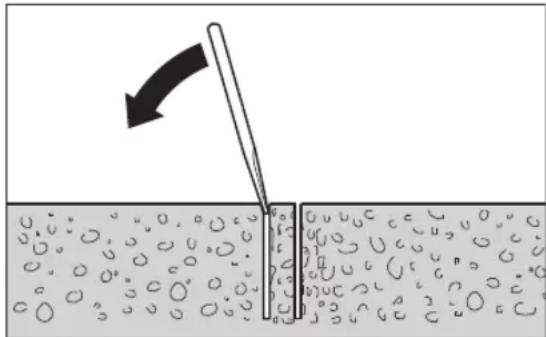
Fixing with an anchor (see figure D)
Drill a separate attachment hole for fixing the drill stand in place with an anchor (accessories) in masonry or concrete.
Distance between anchor hole and centre of planned hole
| Optimum | 285 mm |
| Possible | 275-375 mm |
The following dimensions apply for the anchor hole:
| Diameter Depth | |
| Masonry 20 mm 85 mm | |
| Concrete 16 mm 50 mm | |
Insert a concrete anchor with expansion wedge or a masonry anchor (32). Screw the quick-clamping spindle (33) into the anchor.
Attach the drill stand and a washer and screw these on using the wing nut (34). Tighten the wing nut according to the levelling using an open-ended spanner (width across flats 27mm ).
Fastening by vacuum (accessory)
To fasten the drill stand by vacuum, you need a commercially available vacuum pump and a Bosch vacuum set (accessory).
The vacuum pump must meet the following minimum requirements:
Volume flow: 6 m
3/h
Vacuum at least: 80% (-800 mbar)
The surface must be smooth and flat in order to fasten with vacuum. Use on plaster or brickwork is not permitted.
Once the vacuum connection has been established, gently attach the levelling screws (18) to the base material so that the drill stand is in a rigid position and the sealing ring relaxes slightly. Otherwise the drill stand will sit very softly on the sealing ring.
In order to connect the vacuum pump and Bosch vacuum set, please read and follow the respective operating instructions.
The safety and operating instructions for the vacuum pump and vacuum set must be strictly observed.
Fixing in place with a quick-clamping column (see figure E)
You can fix the drill stand in place between the floor and ceiling using a Bosch quick-clamping column (accessory). The clamping capacity is 1.7m to 3m .
Place one end of the quick-clamping column on the base plate of the drill stand. The contact surface on the ceiling for the other end of the quick-clamping column must be sufficiently stable so that it cannot slip.
To fix the quick-clamping column in place, read and follow the operating instructions provided with it.
Levelling (does not apply for fastening by vacuum)
One by one, turn the levelling screws (18) in or out until the spirit level (28) (if mounting vertically) is exactly aligned.
Then fix the drill stand firmly in place using an anchor attachment or quick-clamping column.
Inserting/changing the core bit
Before carrying out any work on the drill stand or drill, during work breaks and when not using the drill stand, secure the drill stand against unintentional movement by tightening the parking brake.
Inserting the core bit
Always examine the core bits before inserting them. Only use core bits that are free of defects. Using damaged or deformed core bits may result in dangerous situations.
Clean the core bits before inserting them. Lightly grease the thread of the core bit or spray it with corrosion inhibitor. Screw a 1 1/4" UNC core bit (6) onto the drill spindle (7).
Check that the core bit is fitted securely. Core bits that are attached incorrectly or are not securely fixed in place may come loose during operation, thereby putting you at risk.
Removing the core bit
Wear protective gloves when changing the core bit. The core bit may become hot when the power tool is operated for extended periods of time.
Detach the core bit (6) using an open-ended spanner (width across flats 41mm ). When doing so, hold a second open-ended spanner (width across flats 32mm ) on the two flats of the drill spindle (7) to provide counterforce.
The easy-release element (8) makes it easier to remove the core bit (6).
Connecting the water cooling system
If wet core bits are not kept sufficiently cool during drilling, the diamond segments can become damaged or the core bit can get stuck in the drill hole. It is therefore important to ensure a sufficient feed of water when wet-drilling. When expanding an existing hole, this must be sealed carefully to allow the core bit to be sufficiently cooled.
Connected hoses, shut-off valves or accessories must not interfere with drilling.
Close the water cutoff valve (5). Connect a water supply line to the valve adapter (4). The water supply line can be provided from a mobile pressurised water tank (accessory) or a stationary water connection.
You will need a water collection ring and a wet/dry extractor (both accessories) to collect the water that escapes from the drill hole during wet drilling.
Fitting a water collection ring for water extraction (see figure F)
The water collection ring (see "Accessories/replacement parts", page 23) is intended for use with the drill stand for diamond drills GCR 350 and the diamond drill
GDB 350 WE.
Cut an opening for the required drilling diameter in the sealing cover.
Push the tension spring (35) as far as possible into the gap between the base plate (19) and drill column (21). Make sure that the angled section of the tension spring is facing downwards.
Put the water collection ring in position and place the tension spring on the contact points on the water collection ring. (The lugs on the ends of the tension spring are used to pull the tension spring upwards.)
The tensioning force of the spring will press the water collection ring with its seal onto the surface. Together with the vacuum of the wet/dry extractor, this will prevent water from escaping.
The water collection ring can be turned inside its tension ring in order to put the extraction outlet in the necessary position (e.g. to optimise the water drainage when drilling holes horizontally). To do so, open the lock of the tension ring on the water collection ring, turn the water collection ring as required and close the lock again.
Operation
Changing the drilling angle
Pull the plug out of the socket before carrying out any work on the power tool.
Always retighten all the screws after making adjustments to the drill stand.
Loosen the cap nut (17) using the star handle (15).
Set the drill stand to the required drilling angle using the drilling angle scale (13). Refer to the arrow next to the cap nut (17) to set it exactly.
Tighten the cap nut (17) hand-tight using the star handle (15).
The drill stand must not be inserted until the cap nut (17) of the angle adjustment has been retightened.
Starting operation
Pay attention to the mains voltage. The voltage of the power source must match the voltage specified on the rating plate of the power tool.
- Seek advice from the responsible structural engineer, architect or construction supervisor regarding planned drill holes before starting work. Do not penetrate any reinforcements unless you have authorisation from a structural engineer.
- When drilling holes that penetrate walls or ceilings, always check the area concerned for obstacles. Close off the work site and prevent the drill core from falling by means of formwork.
Function test of the portable residual current device (PRCD)
Before starting work, always check that the portable residual current device (PRCD) (1) is functioning correctly:
- Press the TEST button on the residual current device (PRCD). The red indicator light will switch off.
- Press the RESET button. It must now be possible to switch the power tool on.
If the red indicator light does not switch off when you press the TEST button or it switches off repeatedly when the power tool is switched on, you must have the power tool checked by an authorised Bosch after-sales service centre.
The power tool must not be used if the portable residual current device (PRCD) is defective.
Switching on
Press the RESET button on the portable residual current device (PRCD) (1).
Set the water cutoff valve (5) to flow.
22 | English
To switch on the power tool, rock the on/off switch (2) to position 1.
Switching off
To switch off the power tool, rock the on/off switch (2) to position 0.
Close the water cutoff valve (5). Once work is complete, disconnect the valve adapter (4) from the water supply. Open the water cutoff valve (5) and drain off the residual water.
Starting current limitation
The electronics of the power tool make the motor start softly, therefore preventing the starting current from being too high.
Restart protection
The restart protection feature prevents the power tool from uncontrolled starting after the power supply to it has been interrupted.
To restart the tool, press the RESET button on the portable residual current device (PRCD) (1). Set the on/off switch (2) to the off position and then switch the power tool on again.
Preselecting speed
Three speeds can be preselected using the gear selector switch (3).
The gears are recommended for the following drilling diameters:
-1st gear: 165 - 350 mm
- 2nd gear: 80 - 160mm
- 3rd gear: 55 - 105mm
Working advice
Pull the plug out of the socket before carrying out any work on the power tool.
To drill, loosen the locking brake (16) until the star handle (15) is easy to move. When doing so, hold the star handle in place to prevent the power tool from sliding down in an uncontrolled manner.
Start drilling in 1st gear with low speed until the core bit rotates in the material without vibrating. Then switch to 2nd or 3rd gear if necessary.
During drilling, adapt the feed pressure to the material you are drilling. Drill with consistent pressure. If necessary, pull the core bit gently out of the drill hole to remove the wet drilling debris from the diamond segments.
Use the star handle (15) to turn the power tool down to the required drilling depth. Then turn it back until the core bit is completely visible.
To reach the maximum possible working length, you will need to remove the drill core once it completely fills the core bit. Then insert the core bit back into the drilled hole and drill to the maximum depth.
Overload clutch
If a core bit jams or snags, the power transmission to the drill spindle will be interrupted. If this happens, switch the power tool off immediately to prevent wear and heat build-up.
Dislodge the core bit by turning it to the right and left using a suitable open-ended spanner. Carefully pull the power tool out of the bore hole as you do so.
Overload protection
If the overload threshold is exceeded, the power tool will start noticeably pulsating. Reduce the contact pressure until the power tool starts working normally again.
If the contact pressure is not reduced, the power tool will switch off. You will be able to switch the power tool on again straight away, but you should now continue working with a lower contact pressure.
Removing the core
Once drilling is complete, allow the water to keep flowing for a short while to rinse out the debris between the core bit and the core itself.
If the drill core is tightly seated in the core bit, hit the core bit with a piece of soft wood or plastic to loosen the drill core. If necessary, push the drill core out through the shank of the core bit using a rod.
Note: Do not hit the core bit with hard objects, as this may damage or deform it.
Maintenance and Service
Maintenance and Cleaning
Pull the plug out of the socket before carrying out any work on the power tool.
To ensure safe and efficient operation, always keep the power tool and the ventilation slots clean.
Keep the rack (22) and the guide surfaces of the drill column (21) clean at all times.
Clean the drill spindle (7) once the work is complete. Regularly spray the drill spindle and the core bit (6) with corrosion inhibitor.
In order to avoid safety hazards, if the power supply cord needs to be replaced, this must be done by Bosch or by an after-sales service centre that is authorised to repair Bosch power tools.
Readjusting guide rollers (see figure G)
Over time, the guide rollers can wear down, resulting in play between the guide rollers and the drill column. To eliminate this play, you must readjust both guide rollers on the side with the locking brake (16).
English | 23
Loosen both hex nuts (36) using a socket spanner (size 17 mm).
Then tighten both hex socket screws (37) evenly until the play is minimised.
Then retighten both hex nuts (36).
Transport
You can take down the drill stand while the power tool is still attached. To do this, turn the power tool by the star handle (15) as far as possible towards the base plate to prevent the drill stand tipping over.
To safely transport the power tool, remove it from the drill stand. On level surfaces, however, you can transport the drill stand with the power tool still attached.
Accessories/replacement parts
| Spacer plate 350 mm (GDB 350 WE) 2 608 550 628 | |
| Machine adapter (GDB 2500 WE) 2 608 550 622 | |
| Water collection ring (GCR 350) 2 608 550 620 | |
| Sealing lid for water collection ring (GCR 350) | 2 609 390 391 |
| Fastening set: | |
| - For concrete 2 608 002 000 | |
| - For masonry 2 607 000 745 | |
| Anchor set for concrete 2 608 002 001 | |
| Vacuum set 2 608 550 623 | |
| Rubber seal for vacuum set (GCR 350) 2 608 550 626 | |
| Quick-clamping column 2 608 598 111 | |
| Pressurised water tank 2 609 390 308 | |
| GAS 35MAFC wet/dry extractor | |
| GAS 55MAFC wet/dry extractor | |
After-Sales Service and Application Service
Our after-sales service responds to your questions concerning maintenance and repair of your product as well as spare parts. You can find explosion drawings and information on spare parts at: www.bosch-pt.com
The Bosch product use advice team will be happy to help you with any questions about our products and their accessories.
In all correspondence and spare parts orders, please always include the 10-digit article number given on the nameplate of the product.
Great Britain
Robert Bosch Ltd. (B.S.C.)
P.O.Box 98
Broadwater Park
North Orbital Road
Denham Uxbridge
UB95HJ
At www.bosch-pt.co.uk you can order spare parts or arrange the collection of a product in need of servicing or repair.
Tel. Service: (0344) 7360109
E-Mail: boschservicecentre@bosch.com
Ireland
Origo Ltd.
Unit 23 Magna Drive
Magna Business Park
City West
Dublin 24
Tel. Service: (01) 4666700
Fax: (01) 4666888
Australia, New Zealand and Pacific Islands
Robert Bosch Australia Pty. Ltd.
Power Tools
Locked Bag 66
Clayton South VIC 3169
Customer Contact Center
Inside Australia:
Phone: (01300) 307044
Fax: (01300) 307045
Inside New Zealand:
Phone: (0800) 543353
Fax: (0800) 428570
Outside AU and NZ:
Phone: +61 3 95415555
www.bosch-pt.com.au
www.bosch-pt.co.nz
Republic of South Africa
Customer service
Hotline: (011) 6519600
Gauteng - BSC Service Centre
35 Roper Street, New Centre
Johannesburg
Tel.: (011) 4939375
Fax: (011) 4930126
E-mail: bsctools@icon.co.za
KZN - BSC Service Centre
Unit E, Almar Centre
143 Crompton Street
Pinetown
Tel.: (031) 7012120
Fax: (031) 7012446
E-mail: bsc.dur@za.bosch.com
Western Cape - BSC Service Centre
Democracy Way, Prosperity Park
Milnerton
Tel.: (021) 5512577
Fax: (021) 5513223
E-mail: bsc@zsd.co.za
Bosch Headquarters
Midrand, Gauteng
Tel.: (011) 6519600
Fax: (011) 6519880
E-mail: rbsa-hq.pts@za.bosch.com
24 | Français
Disposal
The power tool, drill stand, accessories and packaging should be recycled in an environmentally friendly manner.

Do not dispose of power tools along with household waste.
Only for EU countries:
According to the European Directive 2012/19/EU on Waste Electrical and Electronic Equipment and its implementation into national law, power tools that are no longer usable must be collected separately and disposed of in an environmentally friendly manner.
Français
Protection anti-redemarrage
Robert Bosch (France) S.A.S.
Calle Robert Bosch No. 405
C.P. 50071 Zona Industrial, Toluca - Estado de Mexico
Tel.: (52) 55 528430-62
Tel.: 800 6271286
Dermed sikres storst mulig maskinsikkerhed.
Sikkerhedsadversler for diamantbor
Dyvelsaettilbeton2608002001
Bosch Service Center
Telgrafvej 3
2750 Ballerup
Pá www.bosch-pt.dk kan der online bestilles reservedele el-ler oprettes en reparations ordre.
TIf. Service Center: 44898855
Fax:44898755
E-Mail: vaerktoej@dk.bosch.com
Bortskaffelse
El-vaerktj, boretander, tilbehor og emballage skal genbruges pa en miljovenlig maede.

Smid参加会议的股东名单
Gelder kuni EU-lande:
Bosch Service Center
Telegravej 3
2750 Ballerup
Danmark
Tel.: (08) 7501820 (inom Sverige)
Fax: (011) 187691
Avfallshantering
Endast for EU-lander:
Stille inn turtallet
Traupoeioic nepotpopepvn Aa
Biodote Tc Tpeic paBouc laBnc TnC tauapoetouc neipotpepoevnc laBnc (15) mexpi Tepu aTny kevtprkn nnu nTc staupoeiouc neipotpepoevnc laBnc.
Hotaupaoei6n nepiotpepeoevn 15) xnpaueei too o w paivbeta npowonnc kata to rpunma ooo kalia to Auaio n aphiio twbiodw otbaon tou dpanavou.
Tia to Tpuunma OtnpwTe TN OtaupoeiN nepiortpeoepoeyn laBn avaloya me tic avaykec, apioptepa n deEiaepeip Tepa naow oTo Niivov npowonnc (26).Tia tvnpaiapeon nC Otaupoieoouc nepiortpeoepoeync laBnc TpaBnTe Tnv duvata npoc ta eW.
Aoapaian nT npowonnc me ppevo akvntoinong
Tia oec tic epyaicc otn Bao nbp anavou,ota biaiemuara
epyaaic kaooc kai oe nepimwn un xpnoanc aopalaote tvn
npowon. Biowte y auto to ppevo akvntooinoc (16).
Tia to tpuinma uotre to ppevo akvntooinoc (16) tooo,
wote n staupoeihc nepiatpepoeveyn lah (15) va npopei va
kiveirai eukola. Kpatne tauroxpova tn staupoei
neipotpepoeyn aBt stahepa, ia va anopuyete ia
aveEeaykn Oiaognan npoc ta katou nektpikou
epyaeliou.
UvapuoAoynan Tnc labc netaopoc oTnAekpko epyaleio
Pivn th eon Tou epyaleiou ia npwn popa aeitroupyia Biodote staepa tn aanetaqopac (9) me Tic Biiec (10) oTo nAekptipko epyaleio.
TOnoTeTnTou nAekpkuOepyaieou (BaeEICovc A-B)
PiooETe, va elai oipiyevo To opevo akivntooinanc (16). H untooxn Tou epyaleiou (27) exi ot n deia nleupa eva dvoia. PiooeEe kata tvn tonoetan Tou npoaapoyea Tou epyaleiou (25) 0T noektpko epayaleio, wote n putn tov npoaapoyea Tou epyaleiou va piaoketal, onw caivteal ony eikova B emian cdeia.
TOnotheTneToVnpoapoyeaepyaleiou(25)To nKtpko epyaieioetai, Wate o npnvec npoapoynic (24) Tou npoapoyeaepyaleiouvaopalaoouv oticavriotoxec eykoneTou nKtpkoepyaleiou. Iepaote TICTeoepic Bioc(23)Tou npoapoyeaepyaleiou kaiBiodote TICkala me eva kebi eawterpoikou efayowou (avoiyka keiiedio6mm).
AOTe Tov ekveTPO neipo (14) me tn OtaupoeiO nepiotpeoEvn laBn (15) kai TpaBnEte Tov mExpi Tepu a Ew ano Tnv unooxH Tou epyaleiou (27). Avapntote to nektpko epyaieio me Tov npooapoyea Tou epyaleiou (25) anv unooxH Tou epyaleiou etai, wate n katw mutn Tou npooapoyea Tou epyaleiou va piaekai niow ano Tov katw neipo Tnc unooxN Tou epyaleiou 0.
Akoumnto nAekptkoepyaleio stny unoboxn Tou epyaieoi 2 kal nepaote tov ekkevtpno neipo (14) gava meaa. ΣfTeTov ekkevtpno neipo me Tn Otaupoei npipotpepoeyn AaBn (15).
To oio eukolou auipatoc (8) diekoaive to aoipo TnC nTnpokopwac (6).
Robert Bosch Sp. z o.o.
IpoHTaHTe Bce yKa3aHnno TExHKe 6e3oNaHcHcN, HnCTpyKuHH, HnIOCTpaHnC nCneHnOuHn
PpeOCTaBHeHbIe BMeTe C HactoUHM 3NeKtpOnHCTpy MeHOM. HecobIOJeHHeN KAKx-NH6 Oyka3aHHbIX NHXe IHCTpyKUn MoKeT CTaTB PnPHHOINopAkeHHa3NeKtpUeCKNM TOKOM, NOkapa H/INH TReKeblx TpaBM.
Coxpahnnte 3TH HNCTpykunu yka3aHn dna 6yduero nCNOB3OBAHn.
NcnoB3OBAHHoe B HactoHux HHCTpyKHX ykaaAHnX NOHrThe 3NEKTPOHNCHTpyMEH' pacnpocptpaHraTc Ha 3NEKTPOHNCPTpyMEH C NITaHHeM OT cETn (C ceTeBBIM SHypOM) HA aKKyMyIaTOPHyb 3NEKTPOHNCHTpyMEH (6e3 ceTEBOI shhya).
PNEyPEXDEHNE!Ia3uNTbOT3eKtpueckoro yda-pa,TPaBMnNojapaBOBpemr3KcNlpyataun3eKTPoHNCTpymENTOB Heo6xOJMoCo6NIOaTb PnpHUNNAHbHbIe Mepbl NO TexHKe 6eONacHOCTN.IpePe TEm,Kak npCTynMbK paBote C3eKTPoHNCTpymENTOM,IpouHTaTe BCEyka3AHNO TeXHKe 6eONacHOCTN Xopo0o coXpaHInTe HX.
Be3onachoctb pa6oeryo mecta
CoepKHe pa6ooye MeTo B uHcTote H xopoOo ocBeeHHbIM. BecnopAOK HnH HeOCBeueHHbe yAcTKn pa6oeryo MecTa MOrY pInBecTn K HeCuaCTbIM CnyaM.
He pa6oTaIe C3NeKtpOnHCTpyMeHTaMn BO B3pbIbO onaChOH aTMocpepe, HAp., cOpEpauei roPouhe XNkOCTH, BOCnMaHEHOUcncra Ta3bl NIN NtINb. 3NeKtpOnHCTpyMeHTb HCKpT, QTO MOKET pNBecTH K BOCnMaHEHIO bIN NIN NAPOB.
BoBpempa6oTbC3eKtpOnHCTpyMeHToMHeDOnycKaIte6n30KBaWemypa6oUeMyMeTyTeTeHNoctOpOHnxNtU.OTBNeKUnCb,BblMOKeTeNoTePrtb KOHTPOhHa3eKTPOnHCTpyMeHToM.
3neKtpo6e30nacHocTb
WTeNCbHnBnKa 3NeKtpOnHCTpyMeHTa DoJXHa noXoHbT K WTeNCbHbHO pO3eTke. Hn B Koem cny- qae He BHocHTe H3MeHeHHB W TeNCbHyO BnKy. He npMehnIte nepexOdbie wTeKepbI dN3neK- TPOHNCTpyMeHTOB C 3aUHTbIM 3aEmeHEm. Hen3-MeHeHHbIe WTeNCbHbIE BnKNi N oXoJaune
TtTeNcJIbHbIe PO3ETKN CHINKaIOT PnCK NopaKeHHa 3neK- TPOTOKOM.
PepoTbpaaTe TeneChbIKoTHAKC3a3EmeHHblMNIOBepXHOCTAMN,KAKTO:CTpy6amH,3nEmeHTAMNOTONHEH,KXOHbIMNIIITAMHHXOIOINbHNKAMN.PpH3a3emehnBaWeroTena nobbiaaetc pck npapaeHH3JIeKTPOTOKOM.
3aunuaiTe 3eKTPOHCTPymENT OdoJn CbipocTH.IPOHNIHOBEHNE BODI B3eKTPOHNCTPymENT NOBlaIwaet PNC NopaxEHN3eKTPOTOKOM.
He pa3peaetcnaonb3oBaTb uHyp He no Ha3haeHHIO. HnKorda He hcnnonb3yte uHyp dnn TpaHcnpOpTHPOBKN HnN NOBBeCKN 3NeKTPOHNCTPymEHTA, HnN DnN H3BneEHNN BnIKN H3 WTeNCenbHOH po3ETKn. 3aun-7aHtE uHyp OT BO3DeHCTBn BBICOKNX TempeaTp, MacNa, OCTpbIX KpOMOK HnN NOBnKNbIX qAcTe 3NeKTPOHNCTPymEHTA. NOBpeXeHHb INN cnTyAHbN uHyp NOBbIwaet PnCK IopaxEHIN 3NEKTPOTOKOM.
Pn pa6ote c 3neKtpoHnCTpyMeHTOM nOd OTkpblIM He6om npmehnTe nproDhble dna 3TOrKa6en- ynnnnten. PpmeHeHne npiroHO rO nIpa6tbi nOd OTkpblIM He6om Ka6eJyDnHHnTe nCHkaet pck nopaKeHn 3neKtpoTOKOM.
EcnH HeBO3MOXHO 36eKaTb npHMHeHn 3eKTPoHHCTpymEnTa B cIbPOM NOMEueHH, NOkHouaTe 3eKTPoHHCTpymENT Ype3 yCTpoHCTBO 3aHTHO OTKIOeHH. PpHMHeHne yCTpoHCTBa 3aunTHORO OTKIOueHH CHNkaet PNCK3eKTPuYeCKOro nopaKeHH.
Be3oNaChocThIIODeI
Bybte BHNMaTeNbHbI, cneIte 3a TeM, yTo DeNaeTe, npoDymaHNo HaunHaTe pa60Ty C 3NeKtpOnHCTpyMeHToM. He NnB3yIteCb 3NeKtpOnHCTpyMeHToM B yCTaTOM COCTOHHN HIN NOB 03DeHCTBHeM HApKOTNKOB, ANKORON HIN NEKAPCTBeHHbIX CpeCTB. OINH MOMENT HEBHMaTeNbHOCTn pnpa60Te C 3NeKtpOnHCTpyMeHToM MOKeT PnIBeCTN K Cepbe3HbIM TpaBMam.
PnHMeHHe TcpeCTBa HINHBHyAaBHO 3aHTbI. Bcerda Hochte 3aHTbIe OUYK.NcNoJIb3oBAHHe CpeCTB INHNBHyAaBHO 3aHTbI, KaK To: 3aHTHOJ MaCKN, OByBN Ha HeCKOJIb3aJeI NIOUBe, 3aHTHOrO WJEMa IIN CpeCTB 3aHTbI OprAHOB ClyxA, B 3aBNCMOCTN OT BnDa pa6ToBtC 3neKTPOINHCTpyMeHToM CHXKaET PnCK NOLyueHn TpaBM.
PpeoTbpaaHte HnpeHaMepeHnoe BKnOueHne 3NeKTPoHnCtpymHe. IpeTe KAK NOKIouHTb 3NeKTPoHnCtpymET K cTeH/nn K AkkMyIaTOpY, NOHtB nHn IpeHoNcHTb 3NeKTPoHnCtpymET, y6eDNTecb, YTO OH BbIKIOUeH. YepKaHne NaIbca Ha BblKnHOaTe Ne TpAHCnOpTnPOBKe 3NeKTPoHnCtpymEHTa IN ONDKIOUeHNE K cTeH NITaHNA BKnIOUeHHORO 3NeKTPoHnCtpymEHTa YpeBaTO HeCuaCTbIMn CnyaAMH.
y6npaTe yctahOBouhHmHCTpyMeHT HnraeHbIe KIOUH Do BKNIOUeHH3NeKTPoHNCTpyMeHa. HcTpyMeHT NIN KIIOU, HaxOJaUNCBO BpauOJeCyaCTN3NeKTPoHNCTpyMeHTa, MoXET npNBecT N TpaBMam.
152 | Pycsckn
He npHmMaTe HeecTecBeHHoe NOLOXeHne Kopnyca TeJa. Bcerda 3aHmMaTe yctOuHBOe NOLOXeHne H coxpaHnTe paBHOBeCne. BnaQadapr 3tOMy Bbl MoKTe LyUWe KOHTpOINPOBaTb 3JIeKTPoINHCTpyMeHT B HeoxnDaHHbIX CNTyaUNX.
Hochtne noxdxognypo pa6oyu odexky. He hochte shnpokyo odexdy u kpaewnna. Depxnte BOONcbl n odexdy Bann OT NOBnXhBix Detanei. Hnpokar odeKda, ykpaewnna HIN DnHHbIe BOONcbl MoYr 6byTb 3aTAYHTb BpaauoUMMnca YactmN.
PnH HAnuHH Bo3MOxHOCTN yCTAHOBKN nbineOTcBbBAIOxN N bIeNc6OpHBx YcTPOHCTNBPOBeprTe NXPnCOeHNHeHNE N PpABINbHOE HcONb3OBAHne. PnMeHHeN EblneOTCocA MOKET CHNHTb ONaCHOCTb, Co3daBaEMyIO PbIbIO.
XopoOoee 3HaHHe 3NeKtpOnHCTpymeHToB, nOlyueHHoe Bpe3yIbTaTe qactoro Hx HcNoIb3ObaHHa, He dONKHO npHBODHTK CaMOyBepeHHoCTn HrHOpHPOBaHHo TexHNKn 6e3ONaChocTHn 6bpaUeHHa C 3NeKtpOnHCTpyMeHTAm. OJHo He6pexHoe DeiCtBne 3a DOnIO CeKYHdb MoKeT pINBecTH K cepbe3HbIM TpaBMam.
BHIMAHIE!Bcnyae BO3HKnHOBeHHn nepe6oBpa60Te 3NEKTPOHNCTPymeTA BCNECTBn NOHOrO HnnaCTHNOI pKePaueHHn 3HePROChA6XeHHn HnIOBpeKJDeHHn CEHN ynpaBHeHHn 3HePROChA6XeHHm YCTAOBHTe BbIKNoUaTeNb B NoIOKeHHne BbIK, y6eINBUnCb,TO OH He 3abNOKpOBaH (npr eoHaUNu).OTKIOUHTe CeTEByIO BNky OT pO3eTK Nn OTCoeHNHTe CbEMhBI AKKyMJIrTOp.3TN M npEOTBpaAaETcR HeKOHTpONpyEmbl IOBtOpHbI 3anyck.
PpmeHne 3KeKtpOnHcTpymeHTa H6paueHne C HMM
He neperpymaTe 3eKTPoHcTpyMeH. McnoB3yTe Dnpa 60bTo bcoTBeCTByuOnm CneuaHbHbN 3eK- TPOHNCTPymeNT.C NOxOJaUIM 3eKTPoHcTpyMeHtOM Bby pa6oTaTe lyuSe H aEDEXhee Byka3aHHom dHaana30- He MoUHOCTn.
He pa6oTaTe c3neKtpOnHCTpymEmToM npn Hnc- npaBHom BbIKIOuOaTeNe. 3neKtpOnHCTpymENT, KOtOpbl He NOdaeTcBAKIOUeHHIO INN BbIKIOUeHHIO, ONaceH IOJKeH 6bIb OTpeMOHTnpOBaH.
PpeTem KaK HacTpBaTb 3eKtpOnHcTpymEt,3aMeHtB PnHaNdxNcoTH Hnn y6HpTa 3eKTPOnHcTpymEt Ha XpaHeHne,OTKnIOUHTe WTeNCelHyTO BnKy OTO pO3eTKn Cetn H/NN BbHbTe,ECm3TOBO3MOxHO,AKkMyJATOp.3a Mepa NpeDocTopoXHOCTn PpeDToBpAuaaET HeNpeDHaMepeHHe BkIoueHHe3eKTPOnHcTpymEtA.
XpaHHe 3NEKtpOHnCTpyMeHTb B HeoctynHom dIeTe MeCTe. He pa3peWaeThe nonb3ObaTbCra 3NEKTPOHnCTpyMeHTOM nUaM, KOTOpBie He 3NaKombi C Hm Hn He uTAnH hactoanx HnCTpykun. 3NeKTPOHnCTpyMeHTb ONaChb B pyKaX HeONbTHbIX nUc.
TuaTeNbHO yXaxHbAte 3a 3neKtpOnHCTpyMeHTOM npHaadJeNcoTAMn. IpOBepaIte 6e3ynpeHyO fYHKUIO H XOD DBHXyUxHcY aCteT ENEKtpOnHCTpyMeHTA, OTCYCTBHe IONOMOK HIN NOBpeXdEHM, OTPH
aTeIbHo BnHIOUOHX HaФyHKNUO 3NeKTPoHHCTpyMeHTa. NObpeXeHHbIe Yactn DoJXh6bITb OTpeMOHTHOBaHbI DO HcNoB3OBAHHN 3NeKTPoHHCTpyMeHTa. IIOxoe 06cnyXHBaHHe 3NeKTPoHHCTpyMeHTOB RABIETCr npuHnHb 6bIbIwO uCNa HeCuaCTbIX cIyaeB.
DepxHTe pekuyuHn HNCTpyMeHT B 3aTOueHHOM nHCTOM COCTOHH.3a60TnBO yXoKeHHbIe pekyuine HHCTpyMeHTbI COCtpbIMn pekyuUM KpOMKaMH pexe 3aKINHBAIOCTn HNX JERcBECTH.
PpMHMeHHTe 3NEKTPoHHCTpyMeHt, pNHaDnEkhocTH, pa6Oue HhCTpyMeHtbl T. N. B COOTBeTcBHN C hAcToaUMM HhCTpyKUHM. YuHTbBAite npn 3OM pa6Oue yCNOBn H BbINONHReMyo pa6Ory. McnoIb3OBaHne 3NEKTPoHHCTpyMeHtOBd HnpeDyCMOTpeHHbIX pa6OT MOXET PpNBECTH K ONaCHbIM CHTyaUHM.
DepxKHTe pyuKn H NOBepxHocTH 3aXbata cyxHMn HcCTbIMN, CneIHTe YTO6bl Ha HNX YTO6bl Ha HNX He 6blNO XIKKOHN KOHCNCHETHOH CMA3KN. CKoJIb3Kne pyuKn H NOBepxHocTH 3aXbATA npenTCTBYOT 6eONacHOMy ObaueHHO C INHCTpyMeHToM H NaOT HAeKHO KOHTPOINPOBaTBero B HENpeBUNDEHHbIX CITyaUNIX.
CepBnC
PemOH3JNEKTPoHnCTpyMeHTaDOnJKeH BbINONHtBcT OToBko KBaHnHnHPOBaHHbIM NepCpHaNOM TToBko C npMHeHHeMOpHnHaBbHbIX 3aIacHBx qacte.3TN M oecneuBaetc6eOanacHOctb JNEKTPoHnCTpyMeHTa.
Yka3aHnno TPO texHnke 6e3oNaChocTH dna dpene nAnMa3HOrO CBepHeHH
B cnyae moKporo cBepeHn OTOBnTe BOy ot pa60ue 30hbl onepatopa Hn HcnoIb3yte yctpoCTBO dnc6opaa KIOKcTn. TaKa mepa npedocToPOXHOCTN oEcecneuBaet cyxOeB pa6oey 30he onepatopa n CHJkaeT pCK npaKeHHa 3NeKTpoTOKOM.
PnBbINHHeHH pa60t, npN KOtOpbIX pa6OuH HhCTpyMeHT MoXeT 3aJeTb CkpbItyU 3NeKtpOnpOBoKy HnCBOI cO6CTBeHHbI WHyp NITAHJ, DEpkNTe HhCTpyMeHT 3a H3OJIPOBaHHbIe NOBepXHOCTn. KOHTaKT C HaxOJaEciC NOHapJxKeHEm IPOBOKDJO MoxeT 3aApIITb MetaIIHueCKNe qAChI 3NeKtpONHCTpyMeHT Ta I PnPBecTH K yDapY 3NeKTPnEeCKM TOKOM.
Bo Bpem anma3Horo cBepneHH nonb3yTeCb cpedCTBaAMn 3auNTbl opraHOB Cnyxa. Lym moKet npNBeCTN Knotepe Cnyxa.
EcnKoPOHcy3aKnHHNo, npekpAHTe npHXm N BblKnHOHTe 3neKTPONHCTpyMeNT. YcTaHOHTe n yCTpaHnTe npuHNY 3aKnHHBaHNAKOPOHKN.
PepenOBTOBnBIM BkIOUeHEm dpEN anMa3HO CBepeHn, BCTaBHeHnB 3aROToBky, y6eHTecb, 4TO KOpONKa CNOcO6Ha CBo6OHD BpaauTbc. EcnKoPOHNKy 3aKINHHIO, DpEn MoKeT He BKnIOuHTbcr, 3JeKTPOnHCTpyMeHT MoKe TbIb NepeRpyKeHn IIn dpEn bAnMa3HO CBepeHn MOKe TcOeHNHTbcr O3aROTOBKn.
PpHKpennna CBePNnNbHyO cTAHHy IIO6eMaMn KpennneHmM K3arotOBke, y6eHNTecb, yTO Kpennne
Hne cnoocbo yedeKbTa 3eKtpOnHcTpyment H He DaBaTb emy nepeBnRaTcbBO BpEm 3KcNpyaTuH. Ecn 3arotOBka cnaB aHH npctar,IO6eMb MoXet BBipBaTbCn CBepnIbHa CTAHHa OTkpENITcOT 3aTOBKn.
PnPKpENnA CBePNnBHyO CTAnHHy Pn NOMoUH BA KyyMHO NNtBi K 3aRTOBKe, yCTaHaBnBaHTe NNTHy HA rNaDkyIO, uNCTyIO, HENOpHCTyIO NOBepxHOCTb. He 3aKpeNnIe CBePNnBHyIO CTAnHHy HA NaMHHPOBaHHbIX NOBepXHOCTAx, HAp., Ha NITKe H NOKpbITHAX H3 KOMnO3nHOHHbIX MaTePhaNoB. Ecnn NOBepxHOCTb 3aRTOBKn HE IaJKA, HEPOBHAR INI HEDOctaTOH O 3aKpeNneHHaB, BAKyMHa NII Ta MOKeT OTdEINbCtOT aROTBKN.
Ipeep CbepeHn H BO BpMa CBpeHn yBeHnTecb,TO BaKyyMa DcTaToHNo.EcnB BakyM HeoctaTOuHb,BAkyMHa NHTa MOKeT OTdENHTCB ON 3arOTOBKN.
Ecn3nKTPoHcTpyMeHTzakpenHeToIbKO npn noMoOn BakyMHO nnTb, CbePnTb pa3peMaetcTOIbKO HAnpaBHeHH KHN3y. Pn nOtepe Bakyyma BaKyyMHNA nITa OTeNlETcR O T3aTOrOBKn.
PnH CBepeHHeN CKB03b CTHeB HIN NIO NOTONK CNEHTE 3a TEM, YTO6bI IIOH IN PA6OaY 3OHa C IpOTNBONOX HOCTOPHO B6IIIN 3aUeHbI. CBePNbHAR KOpOHKa MOKeT BbITN H3 BbICBePEHHO OTBepCTNA HIN BbICBePJIeHHbIK KePH MoKET BbIaNcTb C IpOTNBONOXHO CTOPHObl.
He hcnonb3yIte HactoJHm 3NeKtpOHCTpymEt dnn MOKporo CbepeHnHaH rONOBn. IpoHNKHOBeHne BO- Dbl B3NEKTPOHCTpymEt NObBlaeT pNCK nopaxehn 3NEKPTOTOKOM.
McnoB3yTe COOTBETCTBYUHne MetaHONCKaTEN INI HAXOXJDEHH CNpTaHbIX B CTHe Tpy6 HIN NPOBOKH HIN O6paAHTecb 3a CnpaBKO B MeCTHOK MyHbHOe PpePnHtne. KOHTAKC 3NeKTponpoBDIOK MOXET npHECTN K NOxApY H nopaxEHIO 3NEKTPOKOM. NobpeXDeHne RaOtnPOBOda MOXet pNBCTN K B3pbBy. NobpeXDeHne BOOnPOBOda BeDT K HaHeceHNO MATEpHaJIbHOrO yuepe6a HIN MoXet BblBaTb NopaXeHne 3NEKTPOKOM.
OeBaTe 6yBb Ha HeckoB3cKoN nooWBe. TaK Bbl CMOXe H36ExaTb TpaBM, KOToPbe MOxHO NOLyHTb, NOCKoB3HbUHcB Ha rnaKnX NoBPxHOCTAX.
HnKoIaHe pa6oTaIe C3neKtpOnHCTpyMeHTOM 6e3 npHaaraoJooeroAABTomata 3aunTHoro OTKnIOueHHA (PRCD).
CneDNTe 3a TEM, yTO6bI HN NIOH, pa6OtaUOHe B pa6Ooey 30He, HN CAM HNCTpyMeHT He NOBepraHcB KOHTAKTy C BbIXOJaE BoDoJ.
HmKOrda He otXoIne To 3neKtpOnHCTpyMeHT Do eronnonHO octaHOBN. Pa6ouH HnCTpyMeHT Ha BbIe re MoKET cTb npuHNO TpaBM.
Ipeep MoTAXOM dpen npabnblho c6epehtcBepnnbHyo ctaHny. PpaBnblh a6opka BaxHa dno 6ecneueHHa 63ynpeHoi pa6tbl.
HadeKHO 3akpenHTe dpenHa CBepeHHbHO CTAHHe neped Hauanom pa6oTb. CMeueHne DpeHN B CBepeHHbHO CTAHHE MOKeT npBecn K nOtepe KOHTpOJIa.
MoHTpyTe CBePnHbHyIO CTaHHy Ha TBepDoI poBHO NOBepxHocTH. CMeueHne HIN KauaHne CBePnHbHO HO CTaHHbI IpeNpTCTByET paBHOMeHOMy I6e3oNaCHO My BeEHeHIO dpEN.
CneDNTe 3aTeM, yTo6bI uHyp nHTaHHaHXoHNcBHE 30hbl DeCTBnCBepnHbHO CTAHNbl. NoppeJeH HbIMn CnyTaHHb IuHyp NOBbIaet PICK NopaxHeH NJIeKPTOPOKOM.
He neperpyykaTe CBePnHbHyO cTAHHy H He HCNoB3yIe ee B KaueCTBe IecTHNcbl Nn NnOMoCTa. Npeperpy3ka nn HcnoNb3ObaHne CBePnHbHOI cTaNHbI B KaueCTBe IecTHNcbl MoKET npNBecTH K CMEUeHNIO CEHTpa TIAKeCTNaTaNHbIBBepx IN OPOKNDbAHHIO.
XpaHnTe CBeepnHbHyO CTaHHy B HeoctynHom dIeTe MeTe. He pa3peaHTe NOnb3OBaTbCra 3NeKTPoHNCTpyMeHTOM NmUam, KOTOpBie He 3HaKOMbl C HMM NnHe YHTAN HAcToAUX HNCTpyMeHTbI ONaCHb BYpKaX HeONbITbIX NII.
Ipeep IIO6bIMn pa6oTAMn Ha CBePnHbHO CTAHHe Hnn 3neKtpoepn, npn Naay3ax B pa6ote, a TAKKe ecn Bbl He nonb3yeTeCb CBePnHbHO CTAHHO, 3aXMMTE TopMO3 B CEJAX PpeOToBpaUeHHcnyAHHbIX nepeMeueHn.
3NeKtpOnHCTpyMeHT pa3peWaaTc NOkNIOuTaT TObKO K 3NeKtpOceTH C 3aUHTbIM NPOBOOM H DoCTaTOHbIM XapaKTePNCtHKAMH.
3aKpennnTe CbepnHbHyIO CTAnHy C nOmoIbIO 6enB, Bakyyma (npHaadNexHocTb) HIN 6bICTpo3aJXHMHO CTOnKN BO 36EkaHHe HnepeHaMepeHHORO NepeBopauHBaHnCbePnHbHO CTaHHbIC yCTaHOBNeHHoB Hee dpEnbO anMa3HOrO CBepnHnNCBepnHbKOPOHKn.
CneHTE3aTeM,UTo6bIuHaHnINBBoDJI,coeHHTeHBHeDEtANHBOOyNAHBAIOOeKONbO(npHnAhnEKnOcTB)6bINB6e3ynpeHOMCoCTOBHNMeHHTe NOBpeXDeHbIE HN N3HOWeHbIE DeTANNEpeCNeYIOUMPnIMHeHMe.BbICTyNaHHe BOBIsN3DeTAE 3NEKTPOHCHTpymEtTA NobbIaET PnCK npaKeHHA3NEKTPnueckHM TOKOM.
Onncahne npoodykta n ycnyr

IpoTuTHe Bce yka3aHHH HnHCTpyKuHH No texHnke 6e3onacchoCTn. HecobnoJeHne yka3aHHNoTexHnke 6e3onacchoCTn HnHCTpyKuHH MoXET npHBecTH K nopAkeHHIO 3JIeKTPueCKHM TOKOM, NOxapy HnHn TaKeBbIM TpaB-MAM.
IpoKanyiCTa,co6JIIOJaTe HIIIOCTpaunB Hauane pykoBOOCTBaNo 3Kcnnyatau.
154 | Pycsckn
PpMHeHnNoHa3NaeHHIO
Ipehochaaepnb aHaMa3HOro CBepneHH GDB 350 WE ^+ GCR 350
Dpelenb anma3HOro CBepenHH
3JIeKpOHnHCTpyMeHT npEHa3HaueH nI NCIOb3OBaHnB MBeCTe C OXIAJDAeMbIM aIIMa3HbIMC BcEPINbHbIMN KOPOHKAMN N CNTeMoI NOaU WObl IIN MOKpO rO CBepHeHHMnHEpaJIbHbIX MaTePnaIOB, KaHAp., 6eTOHa, JeNE3oBeToHa N KInpNIuHoi KlaAdKn. 3JIeKpOHnHCTpyMeHT MOxHO KOMBnHnPoBaT b CyTPOrCTBOM dIg OTCoCA (KOLbOM dIyNAIBaHnBAHO BoBI IN BNaRoOTCOCOM/IIb/NEOCOM).
3JNEKTPONHCTpyMeHT pa3peWaeTcra HCNoJIb3OBA Tb TOnbKO B KOM6nHaCn cAnMa3HO CBepINbHO CTAHHO GCR 350.
Pa6oTaB hAa rOIOBo Hpea3pe7aetc.
Anma3ha CBeplnIbHa CTaHHa
AIma3Ha CBePnInbHa cTaHnHa IpeDHa3HaueHa dIy yCTaHOBKN B Hee dpen aIma3HOrO CBePneHn IpOn3BOcTBA
Bosch GDB 350 WE. C NOMOu bHO aAnTepe aNMaMuHHbI 2608550622 MoXHo KpeNTb TaKKe H DpeNb aIma3HOro CBepHeGDB 2500 WE. HcNoIb3ObaTb DpyrHe HnCTpyMeHTb He pa3peUaETcra.
AIma3HyIO CBePNbHyIO CTAHNY MoXHO 3aKpENMb c NOMOb6bICTPO3aXMH0C TcONn HA NOy nNn Ha cTeHe. AIma3HyIO CBePNbHyIO CTAHNY MoXHO 3aKpENMb c NOMOb6BAkyMa (npHaJNeXHOCTb) Ha NOy i (c NOMOb6doONHInTeBHoro KpENNEHn) Ha cTeHe. KpENNEHne HAD r IOBOH He pa3peWaeTcR.
AIma3HyIO CBePnIbHyIO CTaHHy MOxHO 3aKpeNITb c NoMoUb6bICTpo3aXmHOn CToKn Ha nOy. KpenneHe HaCTeHe nn HAD rONOB He pa3peWaeTcra.
H306paXeHHbIe coCTaBHbIe qACTn
Hymepaun H3o6paXeHHbIX KOMNHOHTOB BblONHeHa nO pncyHKam 3neKTPoHnHCTpyMeHTa H CBePnHbHO CTAHHb Ha cTpaHnaxc H3o6paXeHHem.
Dpenb anma3Horo CBepenHHa
(1) ABTomat 3aunTHoro OTKIOUeHn (PRCD)
(2) BbiknouateBb
(3) NpeeknouateI nepeaay
(4)ΦHTINHДПЯ NOKJIHOYENI K Kpahy
(5)3anopHbI KpaH dIa BOpbl
(6) CbeprnblhaKopoHka
(7) CBePnHbHbI WnHdJIb
(8) bǐctρo OTnyckaembì ǎnemeHT
(9)PyuKaДЯп repeHocKn əJIeKtpoDpeN
(10) BnHTbIpyKnIypeHocKn 3neKtpoepenn
A) N3o6paKeHHbIe HnONncaHHbIe npHaadneXHocTH He BXOJAT B cTaNAPThbIO6bEM NOCTABK. POnHbI accOPTMENT pHaadneXHocTeB bHaJaTeB HaWeepnpPamme npHaadneXHocTe.
Anma3HaB CBePnHbHaCtHaHa
(11)PykaДЯп repehoCKn CBepnHbHOI CTAHHbI
(12) BnHTbI pyuKn dIa nepeHocKn CBepInlbHo CTAHNbI
(13) kana yra cbepeHH
(14) ΘΚCUEHTPηκΟΒβύ ΜΩΤ ΠρηεΜΗΟ ΟΤΒερχήν ΑΟΥ έ
(15) MaJIbTmCKoe KONEco (c H3OJInpoBAHHH NOBepxHOCTbHO)
(16) CToOpHbIy TOpMo3
(17)KoIIaKOBaIraKaIpaIpyIINPOBaHnYrNa CBepeHn
(18) HNBeHnPHbI BnHT
(19) HxHnIuTOK
(20) Bóoynabnbaiooee KoIbIoo
(21) CBeprnIbHaJ KOnoHHa
(22) 3y6uatarpeika
(23) BnHtby aadantepa dna MaunHbI (M8×20)
(24)Пизмату检кneшнoknадanTepeДЯmaHbI
(25)AanTepeMaHnHbI
(26) ⅢeCTepnnoaui
(27)IocaoDooHoeOTBepCTne INHCTpyMeHTa
(28)BaTePnacDnBbBepKnNoBepTnKaN
(29)PacnpnHa nIITa
(30) BnHTbI paCnOpHoi nHTbI (M8×45) A)
(31)PnImaMThueckne uonOHKn paCnOpHoi nTbI A
(32)ДибьдяКamehHOnKnaKn/6eToHa
(33)БуICTpo3aJxMnHOnI WmHdEnb
(34)Барашковая райka 6bICTpo3aЖMHOrO wHnHdienA
(35)ПужнаньоулайbaюшeroКольца
(36) WecTnRpaHna raKa hAnpaBnIooero pOIIka
(37) BnHT C BYTpEHHM WecTnRpaHHKOM HAnpBaNHOJero pOJIKA
A) N3o6paXeHHbIe HnONcaHHbIe npHnADneXHOCTHe Bxo- dT B cTaNdPthBIO bSeBm NOCTABKn. POnHbI accOPTMENT pNnHAdNeXHOCTe BbHaNDeTe BHaWEI npPorpAMMe npHnADneXHOCTe.
TexHHueckne daHhble
Ipehochajdpnb anma3HOro cBepneHH GDB 350 WE +GCR 350
UTo6bI 3BLeuey 3NeKtpOnHCTpyMeHT H3 CBepnHbHO CTaHnHbI,JeHCTByTe B O6paTHoO uepeHocTH.
PacnpHnA HNTa DnI dHaMeTp a BbcBepnBaemoro OTBep3TH 300-350 MM (cm. pnc.C)
IITOBEPTHINAMETPOMOT300MMoMAKc.350 MM HxHNO DIOONHHTENBHO BCTABNTb paCnOPHyIO NHTy (29) (pInHaNDJExKHOCTb).
ДлгэТOrOустановITEадаNTeРдЯMaunHbI(25)Ha paCnOPHyIOПNTy(29)TakHMOBp3OM,YTO6blPnH3MaTHUeCKNHE WOnHKn(24)aДАNTePaДЯMaunHbIBOWINB3aCenJIeHHe B COOTBetCTByOuNX Na3ax paCnOpHoiПNTbI.
Iocne 3TOrO yCTaHOBtpe pacnOpHyIOIITy (29) c aadantepom dmaunHb5 (25) Ha 3eKTPoHNCTpymEnTakmM o6pa3OM, qTObI np3MaTHueckNe uNOHK (31) pacnOpHOIINb BOUIN B3aueJIeHNE B COOTBETCTBYUHX naax 3eKTPoHNCTpymEnTA. BCTABTe 4 BNHTa (30) pacnOpHOIINb H Tyro 3aTAHHe IN KNIQUOM-WeecTNrPaHHNKOM (pa3-MepOM 6 MM).
3aKpeHnTe 3eNkTpOnHCTpyMeHT, KaK OINcHo Bblue, B CBePnBHO CTAHHe.
3aKpeIeHHe cBepnIbHoI cTAHNHi
Yka3aHHe: 3aKpePnIe TcBepINbHyIO cTAHHy 6e3 a3Opa. 3TNM Bbl ppeoTbpaIaeTe 3aKJIHHBaHHe CBePInbHOJ KO- P0HKN BblAmblBaHHe ceMeHTa.
3aKePHeTe CBePNbHyIO CTaHHy B 3aBNCMOCnOT Oc06eHHoCTe OCHOBaHN C NOMOsbIOIIOBEn, BAKyMa Hb6bICTPO3aXHMHO CTOKn HAD 3aIIaHnpOBaHHbIM BbICBepJIbBaEMbIM OTBepCTHE.
POnHIOHOPOBAHHe CBePnHbHOI cTaNHBI nepei 3aKpeIIeHHem
OTMeTbTe Ha OCHOBAHN CEHTp IpocBepnHBAeMOrO OTBepCTna.OTMeTbTe BHeHHe rabapntb CBepeHbHOKOPOHKn,
cKOTOpOBBbC6HpaeTcpeBa0TaTB,ueHTpOMcnyKHT 费HTP BbICBepnHBAeMOrO OTBepCTnI.
3aKpeHnTe CbepnInbHyUcTaHnHy (co BCTaBHeHHbIM 3neKTPoHNCTpyMeHTOM) C NOMOUsbIOIIO6eJI, BaKyymA HIN 6blCTPO3aXmHNO CTOnIK TaKIM O6pa3OM, TTo6bl MOHTIpOBaHHa CBepnInbHa KOpOHKa COBnaDana C HApNCOBaHHbIMHapyKbIMrBaapntAMN.
KpenneHn cnoMoOnbNoIIO6eNa (cm.pnc.D)
IaC6bpaHnBbCTynaOuE npn CbepeHn BoDbl BAM nOTpe6byTc BOOyNAbINBaHOoee KOnbU N BlaTOOC/IIbcoc (H TO, HpyroepnpHaNDexKHOCTN).
MOnTAX BDOyNABnBAIOUeRO KONbua Ha BnARoOTcOC (CM.PNC.F)
BdoynabnBaOooe konbco (cm. PnpnaDneJXHOCTN/3aIaCTn", CtpaHnca 159) npedHa3NaHeo dIn NCNoJIb3OBAHIN BmecTe c aIma3HOb CBePnIbHO CTAHHO GCR 350 n dpenbAoMa3HOrO CBePNeHg GDB 350 WE.
IpopeXbTe OTBepCTHe IaHyKHOI OHaMeTpapnpocBepnBaEMOro OTBepTByNtOHHTenbHyIO KpbIiKy.
BCTaBbTe npyKHy (35)do ynopa B mJeIb MExky HxHHM ⅢTKOM (19) nCBepnIbHoN KOLOHOH (21).CneIte 3a TEM, YTO6bI N30rHYaT aYb TpyKHHb CMOTpeHa BH3.
YctaHOBHTe BDOOyNAbINBaIOoOee KOBHcB HxKHOe NIOXKeHne I NOOXHTe npyKNHy Ha ONOpHbte TOckn Ha BOOyNAbINBaIOoEM KOJIbCe. (A3bUKn HA KOHcax npyKHNb CnyKaT DnI BbITrNBaHHN ppyKHNb BBepx.)
IoiJeCTBnEM npyKnHb BOOoyaBnBaIOoee KOBlu npKHMaETC yNLOTHEHnEM K OCHOBAHHIO HnpDoTBPaaet B KOMHNauCN BaKyymom, CO3DaBaEmbIM BlaFOOTCOCOM/IIIEcOCOM,BblCTynHne BObl.
BoOyNaBnBaIOoee KOIbO MoKHO NOBOpaHbT B npeDenax erO 3aJHMHO KOIbua dIy NOBOpTa naTppy6ka OTcO Ca B HxHoe NIOXeHne (HaP..,dIy ONTMn3aun CTOKA BObI npri RopNtAlbHbIX OTBepCTnx).OTkpoTe dIy 3TOrO 3aMOK 3aJHMHO KOIbUa Ha BOOyNaBnBAIOuE M KOJIbCe, NOBepHHe BOOyNaBnAOoee KOIbO B HxHoe NIOXeHne I ONTb 3aKpOte 3AMOK.
Pa6ota c HhctpyMeHToM
H3meHenHe yrna cBepnEnHa
PepednIO6bIMMaHNNyIaIcMnCneKtpOHNCTpyMeHTOM BbITACKBaIte WITeNCJIb H3 PO3ETKN.
Pocne kaxdo npepenactpoKn CBepnIbHO CTAHHbI ONrTyro 3aTARnBaHTe BCE BHTbl.
OTnyCTHTe KOJINaUKOByIraIky (17)MaJIbTnIckHM KONECOM(15).
158 | Pycsckn
YCTAHOBHTCBEPIINbHyIO CTAHNY NO 5KANE yrna CBepNEHn (13) HA HJKNbIy rOIn CBePENHn. JIN ToHOn HAcTPOKN CJIeNTe 3a CTpeNKoPRAOM C KOIINaUKOBOI RAIKoN (17).BpyHyIO 3aTHeNKe KOIINaUKOByIO RaIKy (17) MaJIbTHNCKM KONECOM (15).
NcnoB3oBaTb CBePnHbHyU CTaHHy pa3peaetcnnb nocTe TOr, KAK KonnaKOBaRaKa (17) dnerpeynpoBaHH yrTa 6yTeOnr Tyro 3aTMyta.
BknloueHne 3nEeKtpOnHcTpymeHa
YuHTbBaIte HapJxKeHne B cETH! HApJxKeHne NCTouHNIKA IITaHHIOJNIXHO COOTBETCTBOBaTb DaHHbIM Ha 3aBODcKoT Ta6NHUKe 3eNEKTPOINHCTpyMeHTa.
Do hauana pa60tbl npokohcynbTHpyMe OTBeTCTBENHO CNEuHaHnCTa No CTaTHKe, apxnteKTopa HnN OTBETCTBEHHe pyKOBOdCTBO cTPOTeJbCTBOM. Pa3pe3aIte apMaTy pToBko cPa3peWeHH nCTaTHKa COOpyKeHH.
Pn npocBepnBaHH CTEN Hn nepeKpblTH O63aTeIbHO npoBepHte COOTBETCTBYUOuNE NOMEeHNHa HAnHne PpenTCTBn. OrpaNTe CtponTehblyUyactOK npeDoXpaHnTE BbcBepEnHbKepnPoTHNB BbIaNAdHnC NOMoCbHbO ONaYbKn.
IpoBepka HcnpaBHOCTyCTPOCTBA 3auHTHOrO OKIOUeHn (PRCD)
KaJdbpa3nepeHnauJompa6oTbI npOBePrrte HcnpaBHOCTb yCTPOCTBa 3aunTHORO OTKNIUeHn (PRCD) (1):
-HaKMMte Ha KhoNky TEST Ha yctpoiCTBe 3aunTHoro OT-KIQUeHn (PRCD).KpaCHbIKoHTpOJIbHbIN HINDKaTOp raCHet.
- HaKmnte Ha KhoNkY RESET. ΝNeKtpOnHcTpymeHT dONJKeH TeNepb BKJIouHtbcr.
EcH KpaChb KoHTpObHb HnHnKaTOp He rachet, ecH Bb HaxmaeTe Ha KHONKY TEST, HnE cH OH ONrTa rachet npB BKIOUeHN 3eKTPoHHCTpyMeHTa, 3eKTPoHHCTpyMeHT HyxHO pOBepNTb BAbotnHPOBaHHcpehCKoB Bosch.
PnHHeCNpABHOCTN yCTPOINCTBa 3aunTHORO OTKIOueHHA (PRCD) pa6oTaTb c 3NeKTPoHNCTpyMeHTOM He pa3pewaaetc.
BknoueHne
HaKMTHe Ha KONky RESET Ha yCTpoiCTBe 3aunTHoro OT-KIIOUeHn (PRCD) (1).
IIOBepHnTe Kpaan BoDy B I npoToOHoe NonoJKeHne (5). UTObbl BKIIOnHTb 3NeKtPOHNCTpyMeHT, NepeBnHbTe Bbl- KInOuHaTeNb (2) B NonoJKeHne 1.
BbIKIOueHne
YTo6bI BbIKIOHTb 3JIeKTPoHnCTpyMeHT, IpeEaBnHbTe BblKIOUaTeNb (2) B nONOKeHne O.
3aKpoTe 3anOpHbI KpaH BODbl (5).OTcoeDHHte KpaH (4) OTnDaunBODbl. OTKpOte 3anOpHbIKpaH (5) n CneTc OCTaTkn BObl.
OrpaHnueHne npckOBoro ToKa
3NeKtpoHnKa 3NeKtpoHnCTpyMeHTa MAnKo 3anYcKaeT MoTOp H npDoTbpaAaet CnHsKOM 60nbwo NyCKOBOn TOK.
3aunTa oT HenpeDHaMepeHnOro nyska
3aunTaOT HenpeHaMepeHHoro 3aynck npedotBpaaaet HeKoHTpOInpyEmb 3aynck 3eKTPoHHCTpyMeHtA nocne nepe6oeB c3eKTPoCHA6xHem.
Длг NOВТOPHOROBKIIQUEHNAHAKKMITEHa KONKYRESETHa yCTPOICTBe 3aUHTHOrO OTKIOUeHnA (PRCD) (1).YcTAHOBInTe BbIKIOUaTeJIb (2)B NIOLOXeHne BbIKN. IN CHOBA BKIIIOUHTe 3JNEKTPOINHCTPymENT.
HacpoiKa uCnla o6oPoTob
C NOMOJIIO nepeKIOUaTeIeNpepaTc3MOXHO BbIbnpaTb TPNCKOPoTNBpaueHn.
Ipepeayn pekomeHnyIOCTyCnCneHyIOxN DnaMeTPOB npocBepnHbAeMOr OTBepCTHa:
-1-ηpepea:165-350MM
-2-ηpepa:80-160MM
-3-ηpepea:55-105MM
yka3aHHn no npmmeHnHO
Ipeep IIO6bIMM MaHHyIaIcHMa C3NeKtpOHCTpyMEHToM BbITACKBaIte WTeIeCenb H3 po3ETKn.
Дя CBepIeHЯ OTNyCTHe CTOnOpHbI TOpMo3 (16)Ha-CTOnbKO, YTO6bI MaJIbTHnCKoe KONEco (15)JeKo DBIrAnocbПиЗТOM KpeNko DePxNte MaJIbTHnCKoe KONEco BO H36ExHaHne HeKoHTpOJIHpoBAHHOR cNoJI3aHnE 3NeKTpOINHCTpyMeH-Ta.
HaunhaTe CbePnTb Ha 1- nepeDaue c MaIbIM uCNOM o6oPoTOB, noka CbePnNbHaj KOpOHka He HauHET BpaaTaBcra B materpnae 6e3 Bn6paun. Iocne 3toro npn Heo6xOmoCTn NepeKIOUHTecb Ha 2-10 nn 3-10 nepeDaCy.
Iabnene npnkaTna 3aBNCNT O npocBepnBaemoro matepana.Cbepnnte c paBHomepehblm ycInhem.BpmeOT BpeMeHn CnERKa BbITraHBaTe CBePnNbHyO KOpOHky I3 OTBepCTNry ydaJeHHN WlAma H3 anMa3HbIX CeMHeTOB.
OnyCTHeMaIbTINCKHM KOIECOM(15)3NEKTPONHCTpyMeHT Ha Hyxkyo Iny6hny CbePneHn. Pocle 3TOrO BpaauTe pyKoRTKy NOaunB ObaPthOM HapBaJIeHN, YTObI CBepInlb-Ha KOpOHKa CTana NIOHOCbIb BNHa.
BceIAX DoCTNKeHnMAKCMMaJIbHO BO3MOXHo paOObey dINHbI 3CBepNIbHO KOPOHKHy BXHO 3BVeCb BcBepLeHHyO cepDcEBnHY, KaK TOnbKO KOPOHKa NIOHOCTbIO 3aONHNTC. Iocne 3TOrO ONrTB CBAbTe CBepNIbHyo KOPOHky B BcBepPiBaemoe OTBepCTne n CBepInte Do MaKcIMaJIbHO Iy6HbI.
ApmenHn,A3ep6aJxKan,Ipy3n,KpRn3ctan,MOnro- n, TaXKnKCTAH, TypkMeHCTAH, Y36KeHCTAH
TOO «PobepT Bou» (Robert Bosch)
Power Tools noclenpoedxHoe 6cbnyKbAHne npocneKT
PainbIM6eka 169/1
050050AImatb,Ka3axctah
Cnyke6ha n. nouTa: service.pt.ka@bosch.com
OΦηιαλήν έύνην Βεδ-σατι: www.bosch.com, www.bosch- pt.com
Yttnn3aun
OTcnyKBWHe CBOI cPOK 3JNEKTPOINHCTpyMeHTbl, CBEpINbHbIe CTaHHbI, pINHaJIeXKHOCTn IyNAKOBYCneDyET CdaBaTb Ha 3KoONrHuEeCKn UChTyO peKyNepaMuO OTXoOB.

YTNIN3Npyte 3NEKTPONHCTpyMeHT OTdEHLHOOT6bIbTOBO Mycopa!
Tonbko dna ctpan-uehOB EC:
B cootBeTcBn c Ebponecko dnpkeTb0y 2012/19/EU 60tpa60taHHbx 3neKtpueeCKHX 3neKtpOHHbIX np6opax H ee npeo6pa30BaHmE B haunohanbHOe 3akoHdaTeIbCTBO HeroDhble 3neKtpOnpH6Opbl HxNHO co6HpTa 0tJeBHO n CdaBaTb Ha 3KOLOHueCckn uChTyIO nepepa60Ky.
yKpaIHcbka
Bka3iBkn 3Texhikn 6e3nekn
3araanbi 3actepexehn n eneKtponpnaiaB
NONEPE-IXKEHHA
IpoountaTe BcI Bka3iBKn 3Texhikn 6e3neKn,Inctpykui,InIOCTpauiTa CneuphiauH,Haahi 3 uM
eneKtpoHCTpymeHOM.HeBnKOHaHHYycix noaHnx HNkue iHCTpyKuIM MoKe np3BecTH Do ypaKeHHE neKtpuHMM CTpyMOM, noXekj i/abO cepNo3HOITpaBM.
I6pe 36epiraTe Ha Maib6yThe ci nonepeJxKHeH I Bka3iBKn.
PiNnHATTAM (eneKtpoiHCTpyMeHT) B uX 3aCtepeKeHHx MaTbcaHa yBa3i eNEKtpoiHCTpyMeHT, 0p npauoe BiD MepeXi (3eneKtpokaBem) abo Bi d akymyIaTOpHOI bataei (6e3 enektpokaBeno).
YBAIATI 3axHCTy BID ypaXeHHE enektpnHMM CTpyMOM, TpaBM Ta IIOKeki iN dac pObot 3 enektpoIHCTpymentamn Tpe6a 3BaJatn Ha npHcINOBi npabNt a 3TexhIK 6e3neKn. Ipepe ekCnnyataucio enektpoiHCTpymenty npouHTaTE BcI BkazBKN 3 TexhIK 6e3neKn i do6pe 36epekitbix.
Be3neka ha po6o4omy micui
TpmaTe CBOe po6oue Mice B uHCToti 3a6e3neuTe Do6pe ocBtIeHHra po6oUro Mica. Be3naI a6o noraHe OCBITIeHHHa po6oUOmy MciJ MoKytb Pn3BeCTn Do HeuacNHx BNnAdkIB.
He npaioiTe 3 eKeTPOiHCTpyMeHToM y cepeobnui, de icHy e He6e3neKa Bb6yBhAcniok npncTyHOcti ropOuNx piHn, ra3iB a60 nnny. EKeTPOiHCTpyMeHTn MOxytb nopOjXyBaTH iCKPn, BiJ AKNX MoKx 3aMaTnCn nn a6o napn.
Piic npa3 enektpoiHctpymeTOM He nipnyckaTe do po6oOro Micra dite Ta iHnx
HIOeBnMOKeTe BTPaTHN KOHTpObHaI eNEKToPiHCTpyMeHToM, RaI0 Bn He 6yTe 3ocepEkeHi HBAKoHaHHpoBtN.
EneKtpnHa 6e3neKa
UTeTcENb eNkTpoiHCTpyMeHTa NOBHeH nacyBaTHdo pO3eKn. He 03BOJnCTbC mIHATn UOCb B wTeNCenI. IpaobTN 3 eNkTpoHCTpyMeHTAMn, 1o MaOTb 3axHCHe 3a3EmHeHH, He BNKOpHCTOByTe aADANTepn. BInKOpHCTAHH opirihalhHO tWTeNCenTa HAnEHXoI po3eKn 3MeHwYe pN3NK ypaXeHHra NkETpHUM CTpyMOM.
YHKAte KOtakTy qactHH tina i3a3eMneHHN NOBepXHMn, Hap., Tpy6amn, 6aTapeAMn onaeneHH, NHTAMn Ta XOIOHNbHKAMn. KOni BaWe tino 3a3eMneHe, icHy 36iNbweHa He6e3neKa ypaKeHH eNEKTPuHMM CTpymom.
3axnauTe eneKtpoiHcTpymEnbIDouyiBOIOM. IonoaHaHBAOINBEneKtpoiHcTpymENT36inbWye pN3NK ypaKeHHe neKtpuHMM cTpymom.
He BHKOPNCTOByTe MepeKHN WHPy XHBnEHn He 3a np3haueHHM. HikOnn He BHKOPNCTOByTe MepeKHN WHPy DnA nepeHecenHa 6o nepetryBaHHn eNEKtpoiHcTpymEnTa a6o BHTraHHa Wtencen3 po3ETKn. 3axuaiTe Ka6eBb BiD tenna, MaCTnla, roCTpNx KpaIB Ta pyxomnx DeTanei eneKtpoiHcTpymEna. N0sKOJKeHN a6o 3akpyehn Ka6eBb 36ilb7ye pN3NK ypaXeHHn eNEKtpnuHm CTpyMOM.
Длзвишхрбгпбгнькогунггггггггггггггггггггgnggnggnggnggnggnggnggnggnggnggnggnggnggnggnggnggnggnggnggnggnggnggnggnggnggnggnggnggnggnggnggnggnggnggnggnggnggnggnggnggnggnggnggnggnggnggnggnggnggngg.
30bhihixp6it. BnKOpHCTaHHNoOBxByBa, IO npHaTHN Dn
po3paXoBaHH Ha 3OBHHi po6OTh, 3MeHwYe pI3NK
ypaxHeEJIeKTpyHMM CTpyMOM.
Akuo He moxHa 3ano6irTH BHKOpHCTAHIO eNekTPOiHCTpyMeHTa y BOIOTOMy cepeOBnui, BHKOpHCTOByTe npHcTPI 3axHCORO BHMKHeHHBnKOpHCTAHNI pncTPOIO 3axCHOrO BIMKHeHH 3MeHwE pN3IK ypaKeHHNEKTPuHm CTpyMOM.
Be3neKaIIOdei
6yBte yBaXHHM, cnIkyTe 3a TMM, 0o Bn po6nte, ta po3cyDINBO NOOBtce nI qac po6OTn 3 eNEKtpoiHCTpyMeHTOM. He KopHCTyTEcE eNEKtpoiHCTpyMeHTOM, kIoo Bn CTOMJIeHI a60 3hAxOHTeCnI dIeHO HApKOTNKIB, CnIPTHNX HANOIB a6o NIKIB. MItb HeyBaXHoCTI pN KOpHCTyBAHHI eNEKtpoiHCTpyMeHTOM MOKe PnIHBeCTN DO cepH03HX TpaBM.
BnKOpHCTOByIte 3ac06n IHINbIpyaIbHoro 3axNcTy. 3abKn BpaIae Tze 3axNCHIOkynp. 3actOcyBaHHa 3ac06IBIHINbIpyaIbHoro 3axNcTy DnBIDIOBNHX yMOB, HAp., 3axNCHOI MACKN, CNEU8yTT, UO He KO3aCTbCRA, KackTa HaByuHKiB, 3MeHwye pN3NK TpaBM.
YHnKaTe BnnaKOBOro BMnKaHH. NepHix yBIMKHyTH eNEkTpoiHCTpyMeHT B eNEkTpOmepexy a60 nIi'cHaTH AkMyNtOpHy 6aTaPeIO, 6paTH NorO By pyKn a6o nepeHoCHTn, BnEBHITbcra Tomy, 10
eneKtpoiHCTpymeHT BmKHeHH. TpMaHH naBpuHa BmHKaui niuc nac nepeheceHH eneKtpoiHCTpymeHTa abo NiikNoeHH B po3ETky yBIMKHyTORO eKtpoiHCTpymeHTa MoKe np3BecTH do TpaBM.
PpeTm,AK BMkAtn eKeTpoiHcTpymENT, np6epitb HanaorDxyBaIbHi iHcTpymENTa 60 RaIKOBNI KIOU. Pepe6yBaHHa HanaorDxyBaIbHorO iHcTpymEnta a6o KIOUa B uactHI eKeTpoIHcTpymENTa, 10 o6ePaTeBc,MOKE pIN3BeCTN Do TpaBM.
YHnKaIe HEnpHpoHOro NOnOKeHHaTina.3aBXn 36epiraTe CTiKe NOnOKeHHaTa TpMaIte pIBHOBary.Lc Do3BOJNTb Bam KpaAe KOHTPOHOBaTH enEKTPOHCTpyMeHT y He63neuHX CNyauix.
BdraTe npdaTHn OJr. He BdaTne IpocToPi OJr Ta npkpcn. He ndaTne BoNocn OJr Do Detaneu, pO pyxaoTbc. IpocToPi OJr, DOBc BOLOCC Ta npkpaCm MoKyTb Notpantn B DeTani, 0o pyxaOTbcA.
Akyo ichye moKnBictb MOHTyBatnnnoiDCMOKtyBaJIbHI a60 noNooyNBoIIOUoi npHCTPOI, nepeKoHaTeca, 06 BOHn 6yHn Do6pe nID'edHani Ta npabInbHO BnKOpNCTOByBaHc. BnKOpCTaHHnIOBIDCMOKTyBaJIbHO rnpCTpO MoKe 3MeHINTH He6e3neK, 3ymOBNeH iINOM.
D6pe 3haHH enektpointpymentib,OTPMaHe B pe3yblatI qactoro IX BHKOpHCTAHHa,HE NOBHNO np3BOHTN DO CAMOBNEBHeOCTi I rHOpYBaHH npHcINIB TEXHIK 6e3neKn. He6epexKaIIMoKe B ONDHY MNTb Pn3BecTIO BAKKOTpaBMN.
IpaBnIbHe NOBdoXeHHa Ta KOpHCTyBaHH eNekTpoHCTpyMeHTAMM
He nepeBaHTaxyIte eneKtpoiHCTpymENT. BnKOpNCTOByIte TaKNI eNEKtpoiHCTpymENT, 0cneuaIbHo np3HaueHd nB iDnobiDHO p6oTH. 3 npdaTHIM eneKtpoiHCTpymENTOM Bu 3 MeHUM pn3NKOM OTPMaTe KpaU pe3yNbTaTH p6oTH, Ako 6yDeTe npauOBaTH B3a3HaueHOMy dianaoHOTnyxHocTI.
He KophctyIteca enektpointcymeHOM 3 NOWKoDKeHHBMnKaayem. EneKtpointcPymeHT,AKN He BMnKaetbca afo He BmNKaetbca, e He6e3NeuHM i Ioro TpeBa BiipemOHytBaTH.
Ipeep THM, AK perynIOBaN 10e-He6ydb B eNEKTOINCTPymEtI, MinrH nPiHaJa a6o XOBaTH eNEKTOINCTPymEt, BHTARHtB WTeNcEnb i3 po3ETKn Ta/a6o BHTARHtB akMnyTOpHy 6aTapeo. Li IonepeJxkyBaJIbHi 3axOJN 3TexHNI K6eTIeKN 3MeHUYOTb PN3NK BnAadKOBOrO 3anyCkY eNEKTOINCTPymEtHa.
XoBaHTe eneKtpoiHCTpymEnTH,AnHMn Bn came He KopnctyeTecra, BID diteH. He do3BONaHTe KopnCTyBaTHcEneKTPoHCTpymEtOM oO6am, 00 He 3Haomi 3 Horo pObToIO abo He uTANu ZI BKAzIBKn. BkOpNCTaHH eNEKTPoiHCTpymEtIB HeDocBiDuEHNM Oco6am MoKe 6Tu He6e3neuHm.
CTapaHNO doTnJaTe 3a eneKtpoiHcTpymeHTamn i npnaDnM. PepeBipraTe, u6 pyxomi Detani eneKtpoiHcTpymeHa 6yH npabnBho po3taoBohai
162|yKpaHcbKa
Ta He 3aIaHn, He 6yHn NoIkwOJxHeHMn a6o y 6yDbakomy IHOMy CTahi, AKN MIR 6h BnHHyTH Ha fynKIOHyBaHH eneKtpoIHCTpyMeHTa. NowKOxHe eneKtpoIHCTpyMeHTN NOTi6HO BiDpeMOHTbAH, nepH HIX KOPHCYBaTHC HmM 3HOBy.Benka KInbKICTb HeuacHx BnAikB CnpHnHaTcNoraHM DOrJIaOM 3a eNEKtPOIHCTpyMeHTaMH.
TpmaTe pi3aIbHi IHCTpMyEnH HArOCTpeHMM Ta B uHctOTi. CtapaHHo DOrnAHyTi pi3aIbHi IHCTpMyENTH 3 roCTpM p3aIbHM KpaEM MeHWe 3acTpIbTa IeRtWi B EKcNpyataui.
BnKOpHCTOByte eNekTPOiHCTPymENT, npnaadn do hboro,po6oui iHcTpymEnToIO BIDNOBIdHO do uNX BkazibOK. Bepitbdo yBaHN npu cybomy yMOBN poBOT Ta cneunphiKy BnKohyBaHOi pObotn. BnKOpHCTaHHe neKTPoHCTpymEnTiB dIra pObit, IJRAKnx BOHN He nepeD6aueHi, moKe npH3BeCTn Do He6e3neuHx CHTyaui.
TpHMaIe pyKoRtKn i NOBepXHi 3axBaTy cyXHMn i YNCTHMn, cIiKyIte, uO6 Ha HNX He 6yNo OINBN a60 rYcTOrO MaTHa. CIn3bKi pyKoRtKn i NOBepXHi 3axBaTy yHEMOxKNBIOIOb 6e3NeUHe NOBOJKeHHa 3 eNEKTPOiHCTpyMeHToM Ta IHO KOHTPOJIHOBaHH B HeouikyBaHN CuTyauiaRx.
CepBic
BiiDabaiTe CBI eNEKtpoiHCTpymeHT ha peMOHT NHE KBAiifikOBaHH m qaxibcTm Ta NHe 3 BHKOPNCTAHHM opriHnBHNx 3AnuactNH. Lc 3a6e3neuHb po6Otu npNCtPOU npoTAROM TPNBaIOro uacy.
Bka3iBKN 3 Texhikn 6e3neKn dna anma3Hnx dpnib
ypa3i CBePdInHH, kne nOtepe6ye BHKOpNCTAHH BOHN, BiDBoBtTe BOy BiD po6oYOro Micu onepatopa a6o BHKOpNCTOByI npnCTpoI dna 36npaHn pINH. Taki 3actepexhhi zaoDi 3ae3neuyToB cyxictb po6ooi 30Hn onepaTopa I 3MeHwYOTb pn3IK ypaXeHH enEKTpUHNM CTpyMOM.
PnBnBkoHAnHi p6iT, npn JnKx npnnaDn MoKe 3aenntn 3axOBany eneKtpponpOBOky a6o Bnachn HHyp XNBneHH, TpMaite IHCTpyMeHT 3a i30JbOBAHIOBepXHI. 3aenneHH npnlaDn PNOBOKN, IO 3hAxOnIbCn iN HanpyTO, M0Ke npn3BeCTn DO 3apJxHeHH MeTaneBnx qACTNH eneKtpoiHCTpyMeHTa Ta Do ypaKeHH neEeKTPnuHM CTpyMOM.
Piiuc CBepnIHn ANma3Hm dpHnem KOpNCTyTEc3ac06amn 3axncty opraHIB cnxy. Uym moKe noKoHTn cnx.
KkoKopoHka3akHHnnaCpHnHHTb npTHcKaTHIhCTpyMeTdoHn3yIBMKNHTbIhCTpyMeT.3'rcyTe ta yCyHbTe npHuHry 3akHHeHHa
Ipeed noBtOpHHM yBIMKHeHHAM anMa3HOro dpnna y 3arotobui nepeBipTe, u3dHa KOPOHKa BInbHo 0eptatncb. JkUO KopOHka 3aklnHnIacn,dpNb MoKe
He yBIMKHyTnca, iHcTpymeHT MoKe 6yTH nepeBaHTaKeHH a6o anMa3HN dpnIb MoKe BiD'eHaTHC BID 3aTOBKn.
PnPKINIOUOChBepdNInbHy cTAnHHy DIO6eMaHmIKpINHeHHMDo NOBepxHi,NEpeKoHaTeCg,0KpINHeHH3aTHeYTPMHyBaTH eNeKTPOiHCTpyMeHTI He DaBATn HOMy COBatncPiDac BkOpHCTAHH.RAuO nobExHcna6ka afo npHcTa,IO6eMbMOKeBnPBAtncb i CBePdNInbHa cTAnHb BiDipBeTBcB iDnoBepxHi.
3akpinioCbePnHbHy cTAHHy 3a donomoro Bakyymhoi nHTN, BCTahOBIOte II Ha rnaKy, uHcTy, HENOPCHy NOBEXHO. He 3akpinIOte CbePnHbHy CTAHHy HA nAmIOBaHHX NOBEXHX, HAp., Ha nHTci i NOKPTTRX 3 KOMIO3HTHX MaTePiAnIB. Raio NOBEXHA He e pIBHOIO, nIaCKIO a6o do6pe 3akpinHeOIO, nITa MoKe BiipBaTHcBiD NOBEXHI.
Peped BHKOHHnM a6o nIac CbepeHHn HnepeKohTeC, 0u BaKyym DoCTaTHi. RaQo BAkyM HeocTaTHi, BaKyymHa PInTa MoKe Bi'EdHaTcB iD NOBepxHi.
Kyo eKeTpoHCTpyMeHT 3aKpInnEnHH NHe 3a DOnOMoTO BakyymHOI PINTN CBePdHIN ToBONeTBcBKNIOHOOY HAnpMky DOHN3y. y pasi Btpn BakyMy BakyymHaPiTa Bi'EDHyETbcR BiD nobepxHi.
IpeepcBepnHHm Kpi3b CTINH a6o CTNI 3a6e3neue 6e3neky IIOEi i p60oio 30HN 3 INHO 6Oy. KopOHKa MoKe BnHTN Kp3b OTBip a6o KePH MoKe Bnactn 3 INHO 6Oy.
He BHKOPNCTOBYte ue eneKtpoiHCTpyment dna mokporo CbepeHHHaH rONOBOIO. IonaaHHBaOnB eeneKtpoiHCTpyment 36inbWye pni3NK ypaXeHHa eneKtpnHMM cTpyMOM.
ДлзнхodжehнгaxOBAHxB CTHIpy6a60 eNEKtpoPBOOKN KOPHCTyTHeCn PnHaTHHMn npnaadamn a60 3BepHITbcB Micuebe NiDnpeHcMCTBO eNEKtpo-,ra3o-i BOOnocTayHH.3aenenne HneKtpoPBOOKn MOKe np3BOOHTN Do NOkeKi Ta ypaKeHHNeENEKTPuHNM CTPyMOM.3aenenne Hra3OBoi Tpy6MoKe np3BOOHTN Do BV6yX.3aenenne HBAONpOBDOHOI Tpy6 MoKe 3aBDAtn WKOdy MaTepiAlbHm CIHHOCTM a60 np3BeCTN Do ypaKeHHe ENEKTPuHNM CTPyMOM.
BdraTe B3yT, 10 He KOB3aCbC. TaK Bu MoKeTe yHKNHYn NopAHeH, kI MOkyTb BNHNKYTH BHaCNIoK KOB3aHH Ha rJaKnX NOBepxHx.
HikonHe npaOnTe 3 eneKtpoiHcTpymENTOM6e3doHaHOro aBToMaTa 3axnCHOrO BmKHeHH (PRCD).
3BaKaIte Ha Te, 106 IIOH, 10 npauoToB y pOboi 30HI, i Blache IHCTpyMeHT He MaII KOHTaKTy 3 BOIOU, 10 BHXoHTb.
HikonHe BiXoBte Bi Po6OTo IHCTpymEnTa, nOKn BIn NobHicTIO He 3ynnnbCra. Po6ouH iNCTpyMeHt, uO ue pyxaTbcra no Ihepuii, MoKe cnpuHHnTiineChi yWKoKJehn.
IpeaMOHTaxem eEeKtpDnnpaBnBHO BCTAHOBITcBepnnbHy cTaNHy. PpaBnbln MOHTAX E BaxnBm Dnna 3a6e3neueHH 6e3doarHoo pObot npnady.
IepuHX npaObATn 3 eneKtpoDpHnem,HaJIHo 3akpinItb Horo Ha CBepdNlBHi CTAHIni.3cyHeHHra eNEKtpoDpHnBa CBePdNlBHi CTAHHI MOKe npn3BecTn DO BTPaTH KOHTPOHIO.
MoHTyTe CBePdHnBHy CTAHHy Ha TBepdi, pIBHI nobepxhi. RaIO CBePdHnBHa CTAHHa COBaETbCA a6o XHTaCTbCRA, HEMOJIHO pIBHOMiPHo TA BNEBHeHO BECTH eNEKTPODPIHb.
He donyckaHTe noTpannHnn Hhynpa XnBneHH B po6oy 30hy. NooKoJKeHH a6o 3akpyeHH Ka6eb 36iNbuye pnsHK ypaXeHH eEnkTpHuHM cTpyMOM.
He nepehaBaHTaxyIte CBepnInbHy cTAHHy I He BnKOpncToByTe II B JAKoCTI dpa6HHa 60 pHITOBaHH. PnnepeBaHTaxKeHH CBePdNbHOi CTAHnH aBO BNl3aHHHa HcH MoKJIbe 3MiueHHa CEHTpy Baru yropy i nepeBepTaHHa cTAHHH.
36epiraTe CBepeHnIbHy CTAHHy,ЯKHO Bu came He KopHCTyTEcra,daNEKO Bi dITEe. He Do3BOJnTe KopHCTyBaTHcEneKTPOIHCTpyMeHTOM OcO6a,IO He 3Haomi 3 NOro pOboTOO a6o He uHTANu BkazIBKn. Y pa3i 3acTocyBaHHHeNoCbiUeHmM OcO6aMn npnaHn HecTyB Ccoi He6e3NeKy.
Ipeep ycima po6oTAM3i CbepnnHbHOO cTaanHHOO a60 eneKtpoPnHem, y BnnaKy nepepB y po6oti a60 TpHbaIoro HeBHKOpNCTaTHCITb rAblMo dIa 3ano6irAHHaHeHABMCHOMy nepecyBaHHIO.
D03B0JAEbCn iNkHouaTH eneKtpoHcTpymENTnne do eneKtpomepex i3azxHcHm npoBODom i DOCTAHIMXapaKtepHcTKamn.
3aBXnHaIiHo 3aKpInIIOte CBePdNlNbHy CTaHHy 3a DonomorOIO IIO6eIN, BAKyyMy (npHnAID) a6o WbNdkO3aTnCKHO CTiIKN, uO6 yHKnHYn HEhABMnCHOro NepeKnDaHHcBepDnHbHO CTaHHn Nicn BcTaHOBHeHH AnMa3HOrO dpnn i CBePdNlNbHOI KOpOHKn.
Cnikkyte 3a THM, uo6 BOOpOBiDi HuaHn, 3'EDHyBaBHi Detani, a Takox BOOyOBIOBbAbe KInbue (npnaad) 6yn y 6e3DorAHHomy cTahi. 3amHne NooKoJxeni abo cnpaobabi detani nepeHaCTynHM BkOPnCTAHM. BuTIkaHHBOIN 3 dtaneen eektpponpnaNy 36inbwe pniHK ypaKeHH enektpnuHm CTpyMOM.
MOnTyBaHnHa nepeHoCoi pyKoTKn Ha eneKtpoinCtpyment
Ipeep nepuHm 3acTOcyBaHHM MiHOp npHKpyTITb nepeHOCHy pyKoRTy (9) TBnHTaMH (10)do eneKTpoIHCTpyMeHTa.
BcTpomnHH eneKtpoiHcTpymenta (mB. mAn. A-B)
Cnikkyte3aTHM,IO6CTOHOHReIaBMo(16)6yno 3aTARHeHe.
KpInIeHn(27)Ma3 npaBoro 60ky BHTOuy.HaIbaOuH aAnTeP nla Maunnn(25)Ha eNkTPOINCTpyMeHT, cnIKyIte 3a Tm,IOb HocHK aanTepa dna MaunHH 3aBXnD INBHCn pabOpyu,RA Bka3aHO Ha ManIOHkyB.
HaJIbTe aanTep dMaunHn (25) Ha eNkTpoIHCTpyMeHT TAK, 106 np3MaTHiPiIiHKn (24) aanTepa dMaunHn yBiWnB 3aueenneHH y BiNDOBINHx BNTOcKax Ha eNkTPOIHCTpyMeHTi. BCTPOMtB YoTHp I TBnTH (23) aanTepa dMaunHn i MiHO 3aTARHITb IX KIOUcEM-WeCTHRpaHHKOM (pO3MIP 6 MM).
BiDnycttBekCueHTPKOBH nporoHnU (14)MaJIbTiHcKHM KOeCOM (15) i BHTARHITb Horo Do ynpOy 3 KpInneHHRA (27).
Habicte eneKtpoiHcTpymEt p30m 3 aadantepom nMaunn (25) y KpinnHeHH TaK, uo6 HxHHi HocNK aanTepa nn Maunnn 6By 3a HxHkHm nporoHueM KpinnHeHH
BcTpOMITb DnINb B KpInIeHnHa I bepHITb Ha Micce ekCueHTpIKOBn nporoHnU (14).3aTARHITb ekCueHTpIKOBn nporoHnU 3a DonomOrO MoJIbTiKbKOro KOleca (15).
DnB CBePnIHHaHJIbTe MaJIbTIcBKe KONEco (15) 3 npaBOrO a6o nIBoro b60ky Ha WeCTepHIO noaui (26).
Ipebeipte miuictb nocakn enektpohctpymenta B KpinneHHI.
Lio63HnEneKptiHcPymEt 3i CBepeHnIbHOI CTAHHH, BIKOHaiTe iii y 3BOPOTHMy NopAky.
PozipnHa nactnHa dIaMetpa CbepeiHH 300-350 MM (INB. Man. C)
IINOTBOPIBdiametpOMBID300MMoMAKCHMaJIbHO 350MMHeo6xIHNO BCTaHOBIOBaTHOdaTkoBYpo3nipHy nlaactHNY(29)(npnaJAA
IpyoBCTAHOBITb aanTep dmaunn (25)Ha po3npHy nactHy (29) Tak, 06 np3MaTHHi nIIuKN (24) aanTepa dna MaunH yBiWn B 3aueenHeHH y BiNobiDnHex na3ax po3npHoi nactHN.
Iotim BCTAHOBITb po3nipHy pnaCTHHY (29) pa30m 3 aadantepom dmaunnn (25) Ha eneKtpoiHcTpymENTaK, uo6 npn3matuhi niiu (31) po3npHOI pnaCTHH ybiwnB3aennneHHy BiNDOBiDnHex BHTOuykax Ha eNEKtpoiHcTpymENTi. BCTPOMtBuOpn rBNHTH (30) po3npHOI pnaCTHHI miuho 3aTARHITbix KIOHcEM- wecTHrpaHHNKOM (po3mp 6 MM).
Iotim3aKpinitbeneKtpoiHCTpymHTyCBepnblHi CTAHHI,RAONCAHO BUNe.
3aKpInnHcBepdNbHOI cTAHHH
Bka3iBka: MoTyIe CBePdInnbHy cTaNHy 6e3 IIOpTy. LIM Bn yHnKHeTe 3aklnHHoBaHH CBePdInnbHOI KopoHNKa Ta BnpuBaHH cerMeHTIB.
3aKpinitb CBePnNtHy cTAHHy BIDNOBIDHO DO Tnny nobepxhi 3a DonomorOIOIIO6eI, BAKymy a60 WbIKo3ATNCKHOI CTiKN HAD 3aNNHOBAHM OTBOPOM.
POnuIOBANH CBePnNbHOI CTaHH Npep 3akpinneHHAM
BiIMtBeIeHr6baxHOroOTBOpyHaOCHOBi.BiIMtBeTc0BHlHi r6apHTN CBePnHbHOJ KOpOHK,3aDOnOMoHOJkoI B6baxAeTe CBePnHn,IO6ix CEHTpOM 6yB CEHT3aIIaHOBaHOrO OTBOpY.
3aKpinitb CbePnHbHy CTAHNY (3 BCTPOMHeHM eneKtpoiHcTpymEtOM) 3a DonomoroIO DIO6eJI, BakyMy aO bWbNko3aTNCHOI CTIK NtAKM YINOM, IO6 MOHTOBaHa CBepnHbHa KOpOHKa cnIBnadaJa3 HaMaJIbOBaHIMn ra6apntamn.
3aKpInnHeHHIIO6eNm (INB.Man.D)
ДяЗakpinneHЯ CBepnHbHOI CTaHHN DIO6eM (npnaad) npocBepniB OKpemN OTBip B KaMaHIN Knaadi aO bTeOHi.
BicTaHb MIX OTBOPOM nI dIO6eNb Ta cepeHHO 3aHaHOBAHOro CBepDHeHO rO TBOpY
06'EMHa BHTpata: 6 M
3/roa.
BakyyM, He MeHHe: 80% (-800 m6ap)
Ia KpInneHHHa 3a DOnOMoIO BakyMy NOBepXHa NOBHHa 6yTH rnaKOHO pIBHO. BkOpHCTaHH Ha WHTyKaTpyi a60 Ka'MHI KnaDi 3a6OpOHCTbCra.
No 3aBepHHi NiKInuHHe BakyMy, 3nerKa BCTaHObit HIBenipHi TBnHTn (18) Ha NoBepxHIO, 106 CBepDnIbHa CTAHNa CINiina JOKpCTKO i yuiNbHOBaJIbHE KINbIe TPOXN NocnaBnOcR. Y IINOWOM BYNAkky CBepDnIbHa CTAHNa CINITIME Ha yuiNbHOBaHbOMy KINbIci 3aHaTOn M'RAKO.
IiNkUOeHHBakyyMHoroHacocaiBakyyMHoro KOMnEky Bosch npouHTaTe i BIKOHyTe ixHi IHcTpkyi3 eknnyataqii.
ToHNOdoepKyuTEcra Bka3IBOK 3TexHkN 6e3neKN Ta Bka3IBOK 10o0 pO60TH 3 BaKyymHOI NOMIOI BakyymHM Ha6OpOM!
3aKpInnEnHHa 3aDOnOMoHO uBnKo3aTHCKHOI CTiIKN (INB.MAn.E)
CbeepnHbHy cTAHNY MoKHa 3aKpInHTn 3a DOnOMorIOU WbHKo3aTHCKHOI CTIKN Bosch (npnaJa) MIX iDnoroIOi CTeneIO .dianaoH 3aTnCKaHH 3hAxOndbcy y MeKax BiD 1,7Mi3M.
BctahOBITb OINH KIHeCb WBNIKO3aTNCKHO CTiKN Ha HnKHi
HTOK CBePdNInbHO CTAHNN. NObepxHa CTeni,do KAoi
6yde pncstabneHH iHnn KIHeCb WBNIKO3aTNCKHO CTiKN,
NOBHNH 6yTN DOCTaTHBO CTa6bnH i HEKOB3Kn.
I3aKpInnHeHH WbHKnO3aTHCKHOCTiIKN IpOHTaHTe Ta DToPmMyTEcI HCTpyKu3 EKcnNyatau2I Do HeI.
HibenIOBaHHa (He npn BaKyHMoMy KpInneHHI)
3aKpyyTe a6o po3kpyyTe no-Ohomy HibenipHi RBHTH (18)doTHxnip, nOKn BaTePnac (28)(npn BepTtKaJIbHOMy MOHTaxi) He 6yde TOUHO BHPIBHNN.
Tenep3akpinitb CBeprnnnHy cTaNHy 3a donomorIO d6enib a60 wBnKo3atckHOrO cTOKA.
MoTAtK/3aMiHa CbepdNIIbHOi KopoHKn
Ipeep ycima po6oTAM3i CBepnHbHOO cTAHHOO a60 eNEKtpoDpHnEM, y BNAnky nepepyo60ti a60 TpHbAioro HEBKnOPcHAnHa 3aTHCHTb rAnMo dna 3anobirahHH HeHABMNCHOMy nepecyBaHHIO.
MoTaxK CBepnHbHOI KOpOHKn
PepeBipTe CBepnHbHI KOpOKn nepeBCTpOMnHnM. BkOpNcTOByte NHe 6e3OraHHi CBepnHbHI KOpOKn. NooKoJxehi a6o DeopmOBaHI CBepnHbHI KOpOKN MoKyTb np3BeCTn Do He6e3neuHx CHTyaui.
OuHCTiB CBePnINbHy KOpOHky NepeD BCTpOMnHHM. 3Jerka 3MaTcTiB Pi3b6y CBepnnbHOI KOpOHKn a60 no6pn3KaIte Ha HeaANTKOp03iHNM 3acobom.
HaKpyTb CBePdNnBHy KopoHky 1 1/4"UNC (6) Ha CBePdNnBnHnHnHnDeJb (7).
Ipebeipte miuHCTb nocaKn CBepnMbhoKopoHN.
HenpaBnIbHO a6o noraHo 3akpInneHi CBepnnIbHI KOpOHMoKyTb po3xHTaTnci iHapaaNTi Bac Ha He6e3Neky.
3HimannCbePnIbHoI KOpONK
Piic 3aHH CBePnHbHO KOPOKN O6OB'3KOBO HAdiBaTe 3axnChi pykabnK. Ppi TpBaniEknnyataui eneKtpnpnady CbePnHa KOpOHKa MOKe DyKe Harpibatnc.
BiDnyctitb CBePnHbHy KOpOHy (6) 3a DOnOMorOIO BnIKOBOro raiKOBOrO KIOUa (po3mip 41 MM). PnIcbOMy npHTpMyTe dpyHM BNKOBIM raIKOBIM KIOUeM (po3mip 32 MM) DBORpaHHXBOCTOBNK CBePnHbHO 7
WBnKobjDnyckHne enemt (8) nonerWye BdkpyuBaHH CbePnIbHOJ KOPOHK (6).
PikKlueyHn BOJHoro OXONODKeHH
Kuo nuc cBepnHnOxOIOJyBaHcBepnIbHi KOpOHn He DoCTaTHbO OXoIOJxOHTbC,MOJIbNe IOKOxKeHH aMa3HNxCerMeHtIB aBO CBePnINbHa KOpOHKa MoJe 3actpTn BOTopi. Tomy npn CbePnIH3 OXoIOJxHeHcNkTe 3a DOCTaTHbO NOdaeEO BoN. PIn 36InbWeHH Bxe icHyQoRO OTBPuy Noro Heo6xIdHO petenbHo 3aKpHTn dA 3ae3neueHH JOCTaTHbOro OXoIOJxHeH CBePnINbHO KOpOHKn.
Piiknoueni uhaHn, 3aniphi knanaHH a6o npnaHn He noBHHi 3abaxaTH B npocci cpeDnHH.
3aKnIte 3anipnKpaHnnBnO BnD (5).PiKlouitb BOnydo niiEHyBaay4.6pTaNBOy MoXHa 3 nepeHoCHOro HanipHoro 6aka nnBnO (npnaJa) a6o Bi d ctaioHapHoro BOOpOBiHO rKaHa.
163bnpaBDOy,0BCTynae nIacMOKporo CBepnHH,HeoXiHO MaTH BOOyOBIOBaJIbHe KINbue (pHnAD)IBONOROJcMOKryBaU/NNOCMOK(pHnAD)
MOHTAX BOOyOINBOBAnbHOro KInbua DO BONOROBIDCMOKTyBaUa (Mn. Man. F)
BodoynoBIOBAHBe KInbue (INB. "PpnaJIA/3aunactHH" CtopiHa 169) npn3hauehe nIbnKOpNCaHpa30m aIma3HO CBepnINbHO CTAHNOIO GCR 350 i anMa3HM dpnnem GDB 350 WE.
IpopixteOTBIPd76baxaHOro diametpa CBepnHHBA yinbHOBaHNI Kpuu.
BCTpOMITb HATAKHy npyHKHy (35) Do ynopy B uINHHy MIX HNNHIM UNTKOM (19) iCBepdNtBHOIO KOLOHOIO (21).
Cnldkyte3aTMM,uO6BnHyTauaCTHaHaTAAKHOI npyKnH NHBnacBAH3.
BctaHOIBb BOOyoNBOIbAbe KInbue Ha Mlue i BCTpOMiB hataKHy npyKHy HA onOpHi TOkHn H bOIOYOBIOBAHOMy KInbui. (R3uKnHa KINxH HATAKHOI npyKHN CnyrTOB dIe BNTARBAHH HA TAKHOI npyKHN Bropy.)
PiDIIeIO npyKHHBDOoyOBnOBaIbHe KINbue pa3OM 3 yuiNbHHeHm PnTHNcKaETBCa DO OCHOBi pa3OM 3 Bakyymom,IOYTBOpHOETBCBOIROBIDCMOKTyBaeyM/ nIOOCMOKOM,3anobiraBNTiKaHHIO BOH.
BdooynoBIOBAIbHe KInbcMe MoKe NOBepTaHcB MExa HOrO 3aTnCKHO KInbU, Uo6 BCTAHOBHTN BiDCMOKtYBaIbHN NAtpy60k y bKaHa NoNoXeHHa (Hap., IaONTMIsauii BiTOky BoNDiNd Vac rOpH3oHTaNbHO CBepeHH).IaNoBOrO BIDKnPHTe 3AmOK 3aTnCKHO KInb4Ha BOOyNOBIAIbHOMy KInbcI, NOBepHITb BOOyNOBIAIbHe KInbcye 6bKaHa NoNoXeHH i3HOBy 3aKnPiTe 3AMok.
Po6ota
3MiHa KyTa CBepnIHHe
Ppe6yub-akmmMaHinyuaiIm3 enektpponpnaDOMBHTaTcHtBwTeCenb3po3eKn.
PicnKoKHOH HanaWtYBaHH 3aTHcKaTe yci TBHHT Ha CBepdnnbHi CTAHHI.
Bijnytib KObnaKOBy ray (17) MaJIbTiHcBKM KOJecOM (15).
3a donomoroio kkayn Kyta CBepnHHBCTAHOBITb CBepnnhHy cTAHNY (13) nID NOTPi6HMM KytOM CbeppnHH. Jna ToHOro HanaHTyBaHH CNiKnyTe 3a CTpINKO6 bnaKOBNaUKOBoI raKn (17).
BpyHy 3aTnHtB KONaUKOBy rAky (17) 3a donomoro moNbTiCkoro Koneca (15).
BnKOpHcTObyBaTH CBePdNnIbHy CTAHNY Do3BOHcTBcH NHe NiCnTa TOrO, K6Bye 3aTnRHeHa KOBnaUkOBa raKa (17) peryHOBaHH KyTa CBePdInHH.
Noataokpo60tn
3BaxaHte Ha Happyr B Mepexi! Hanpyra B Dxepeni CTpyM NOBHHa BiINOBiTaTH DaHm Ha 3aBOcKi Tabnui eNkTPOHCTpyMeHTa.
Pepen noaTkom p60TH npOKocnytecna 3annahOBAHX CBepeHb 3 KOMTeHTHM ctaTKOM, apxiteKTopom a6o BnKOp6om. Pepepiae apmatypy nhe 3a HABHOCTI O3BOY Bi iHexehepa-ctaTHka.
Pn npocBepnHnCiH a6o nIaIOnn 06OB'3KOBn nepeBipnTe BiNIOBiHi npMiuEHHHa npEpmet nepeWko. NpeKpHnTe 6yDIBeBnMaJdaHnK Ta 3po6Itb onany6ky, uO6 BnCepnHa cepeBnHa He BNnaJana.
IpebeBipka npHcTpo 3axnCHoro BmKHeHHa (PRCD) Ha cnpaBHictb
KoJHoro pa3y nepei noaTkom po60TH nepeBipnTe cnpaBHicTh npNCPTPO 3axCHORBO BmKHeHHA (PRCD) (1):
- Hatncitb KhoNky TEST Ha npncptpo 3axnchoro BHMKHeHHa (PRCD). YepBoHn KOHTpObnHn iHdNkatop rache.
-HaTnCHiB KhoNkY RESET.Tenep eNeKTpOIHCTpyMeHT NOBnHeH yBIMKHYTnC.
AkyuuepBOHn KOHTPOBHy INDnKaTOp He rache, KOHN Bn HaTHCKaTe KHOKNy TEST, a6o kUO Binrache, KOHN Bn 3HOBy BMnKaTe eNEKTOiHCTpyMeH, T0di eNEKTOiHCTpyMeH Heo6xIDHO BiDaTH Na nepeBipKy Do ABTOPN3OBaHOrO cepBichoro ceHTpy Bosch.
Kpnpctpi 3axhcHOro BmKHeHHa (PRCD) HecnpabHnn, KopcTByBaTHc eneKtpoiHcTpymentom HeD03BONCTbcR.
BMKahan
HaHCHITb KONky RESET Ha npHcTpo3axnCHOrOBMMKHeHHa (PRCD) (1).
BIDKpnte 3anipnH KpaH Dn BODn (5).
U6yBIMKHyTN eNkTPOHCTpyMeHT, pHTNCHTb Bmkau (2) B NOJKeHHa 1.
BmNKaHHa
UoB BmKHytn eneKtpoiHCTpyMeHT, pntnCHiB BmHKaU (2) B NOJKeHHA 0.
3akpnte 3anipnKpaH DnB OoN (5).PiCn 3aKiHueHH po60TN Bi'cHaTe Ni'cHyBaY (4) BiD BoN. BdkPnTe 3anipn KpaH DnB OoN (5) Ta daIte 3aJIINKam BoH CTekTn.
06mexeHHnIyckoBOrO CTpyMy
EneKtpoHika eeneKtpoiHcTpymeta 3a6e3neuye M'kN 3anyck DnBryHa i 3anobirae 3aHaTo BnCOKOMy nycKObOMy cTpyM.
3axhcT BiD NOBtOpHOro Ncy
3axnctbID nobTOphoro ncy 3anobirae HEKoHTpObnBOBaHOMy 3anycky enekTPOIHCTpyMeHa nicna nepe6oB 3 enekTponocTaaHHM.
168|yKpaHcbka
Uo63HOByyIMKHyTHeJekTPOiHCTpyMeHT,HaTNCHtB KHONky RESET Ha npNCTpoi 3axnCHOROBIMKHeHHA (PRCD) (1).Iicna yboro BcTaHOBITb BmNKaq (2)y BIMKHeHne IIOKeHHI 3HOB yIMKHTbeJekTPOIHCTpyMeHT.
BctahOBnEnHKnBkOci o6epTb
3a donomoroko nepemkkayu wBukocti (3) Moxha BCTAHOBIOBATn Tpiaana0Hn KInbKocti oebptIB.
Li WbHnKoCT peKomeHnyIOBcra Tn TaKnx DiametpiB p03CBepDIOBAIbHOrO TBOPy:
-1WBnKicTb:165-350MM
-2WBnKicTB:80-160MM
-3WBnKicTB:55-105MM
Bka3iBkn 0oDpo6oTn
Ipeep6ydb-akmmMaHininyuaJIMN3 eneKtpponpnaDOMBNTaRHTbWtencenb3po3ETK.
IINBcBnIHH BIDNCTbCTOHOUHe raBMO (16)
HactInbK, 0o6 MaIbTiMbke KOEnco (15) Ierko pyxanoa.
Piu cBomy MiHO TpMaHTe MaIbTiMbke KOEnco, 0o6
3ao6iTT HeKoHTpoJIbOBaHOMy CNOB3aHHIO
eNEkTPOINCTpyMeHa.
3acBepnHHe OTbip Ha 1- WbNkOcTi 3 HeBeNtKoI KInbKCTO o6eTIB Do Tnx nip, NOKi CbePnNbHa KOpOHKa He bye o6eTpAtnsca Be3 BiBaquin y po3CBepnIOBaHOMy MaTepiani. IOTIM 3a Notpe6n nepeuDItb Ha 2-y a60 3-10 WBNDKCTb.
CnHa HATNCKyBaHH Ha npHnad 3aJenKHTb BiD
po3CBepnIOBAbHOBrO MaTePiany. PpaOne 3 pIBHomipHM
HaTNCyBaHHM. Yac BiD uacy 3nerKa BnBObTe
CBepnINbHy KOpOHky 3 OTBOPY, Uo6 3 aIma3HNx CeMeHTiB
3iWOB CBePDnIHbHn IAm.
3a donomoro moIbIckbKOro Koneca (15) onycitb eneKtpoHCTpyMeHr Ha Heo6xIDHy rNbHy CBepnHH. Picra 3HOBy NiHIMITb NOrO, 6yNo NobHicTIO BNDHO CBePdINbHy KOpOHky.
IJaDocarHHeH MaKcHMaJIbHOIpoOoi DOBKnH Heo6xIDHO BHTaRHy TN BnCBepdNeHcy cepeBNHy,AK TINbKN CBepnnlNbHa KOpONKa NOBhCTIO 3anOBnTbCn. Ncna CboTO 3HOB BCTpOMITb CBepnnlNbHy KOpONky O TBip i npodBxyTe CBepdneHNO MaKcHMaJIbHOI rN6HNH.
3ano6ixkma Myfta
Pn3akHHeHHi a6o cinaHHi CBepeHbHOI KopoHNk npBOD CBepHbHorO uHHNeJBAuHKaTbcra. Y taKOMy BInaKy HeraiHo BmKHITb eJeKTPOIHCTpymEt, 0o6 3ano6irn 3HOeHHIO i neperpiBy.
BiDnyctIb CbePdHnBHy KopoHcy 3a DonomoroIO BiNObiHOro BnKOBOrO raKOBOrO KInOu, NOBepTaIOU HiO npabOpuy i libOpuy. Pnp cboMy oBepeXHO BHTarHITb eNEKTPOINCTpymEt 3 OTbOpy.
3axnCTBIDnepeBaHTaXeHHA
YBnndkypebeueneHHnoporynepebaHTaKeHH
eNEKtpoiHCTpyMeHT NOUHaNc NOMITHOyNbCyBaTH.
3MeHwyTe CNY HATNCKyBaHH,POKN eNEKtpoHCTpyMeHT
He noUHe 3HOBy PauOBAH HopMaIbHo.
Akyo He 3MeHHTn CnHy HATNCKaHH, eNEKtpoiHCTpymeH BmHKaeTcR. Picra zuoro Bn MoKeTe 3HOBy yBIMKHYTH enEeKtpoiHCTpymeHT, ane hadani Notpi6Ho npauObaTu 3 MeHWO O CNIIO HATNCKaHH.
BndaenHn BncBepdnehoCepueBHH
Picra CBepeHHHe nepeKpBaTe BIPAy BOy,06 BMMTN 7nAM MIX CBeepHbHO KOPOHKO I BNCBepJeHOIO cepeBuHOIO.
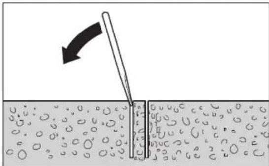
Akyo BnCBePnHa cepeBnHa MiHcNHTb y CbePnblnHi KOpOH, NocTyKaIte MJKM MMaTkom DepeBnH aO bPiactmacn No CbePnblbHi KOpOH, 106 BnTH BnCBePnEHy cepeBnHy.3a NotpeBn BnHTOBxAte BnCbePnEny cepeBnHy cptnKHeM uee3 KHeu CBepnblHoI KOpOHKn, RKM BOHa BCTpOMIOETbc B nnHHJeB.
Bka3iBka:He cykaIe TBePIMn ppeMetamn nO cBePdnnbHi KOpOHU (He6e3neKa deOpmaui)!
Texhuihe o6cnyroByBaHHaicepBic
Texhihe 06cnyrobyaHHia ouhenceHH
Ipeep6ydb-kaHMMMaHinnyaicHM3 eneKtpponpnaJOM BHTarHtB wTeNCb 3 po3ETKn.
Длякioi6e3neuhoipo6oTnTpmaite enektpponpnaiaBentnuaHIOBTbOpBvCHCTOTI.
3aBXnTpMaTe 3y6aCTpypeKy (22) Ta HapPmHi NOBepxHcBepnnbHOI KOHO (21) B uHCTOTi.
Ouuyyte CbepnblhnnwhHneB7)nicra3akHcHnpo60tn.Yac Biy acy 06bpn3kyte CbepnblhnnwhHneB Ta Cbepnblhny KOpOHky (6)aHTNKoP03iHN3ac60m.
Akyo Tpe6a nomiHn iD'EnyBaIbHn Ka6eB, ce Tpe6a pO6HT Ha oipmi Bosch a6o B cepbiHm MaICTepHi dJeNEKtpoHCTpyMeHITB Bosch, 06b yHKHyTN He6e3neK.
IOctyBaHHHaHnPmHnx poHKnB (DHB. Man. G)
3 yacom HaprMHI pONIKMOKytb 3HOuYBaTHcI MIX HMMI CBEpNnBHOKOJNOHO MOKe YTBPOTnca IpocBt. LIO6 ycHyTN CEINPocBt, Heo6xIDHOIOCTyBATn HaprMHI pONIK 360ky cTOnHOrHO raJbMa (16).
BiDnycttbobnDbIweCTnrgpHirraKn(36)TOPueBm KIOUcHem (po3Mip 17 MM).
IotimpiBHomipHO 3aTaryte 06nBa TBHHTN 3 BHYtpiHIM IeCTHpaHHKOM (37), nOKn npocBIT He 3BeDeTbcr DO MIHIMMy.
3HOB MIOHO 3aTARHITb 6oNDI WIeCTNIRpaHHI raKN (36).
TpaHcnopryBaHHa
CbePnHbHy cTahHcy 3i BCTpOMHeHM eNkTPOHcTpymeHOT MOxHa nepeCTaBnTH.ДЯ zufo nepecyHbTe eNkTPOHcTpymeHT 3a DOIOMOROIO MaJIbTIcKoR OKeNa (15) Akomora 6nKue Do HnxHbo rNTKa, 06 nopeDnTH nepeKnDaHH CbePnnHbHOI CTAHHH.
Iio63p06nTH TpaHcnpOyBaHH 6e3neuHiuHM, BmIMtB eNEKtpoiHCTpyMeHT 3i CBepdNInbHOI CTaHINH. Ha pIBHX NOBepxHx CBepdNInbHy CTaHHy MOXHa TAKOX TpaHCnOptyBatn 3i BCTPOMHeHM eNEKtpoiHCTpyMeHTOM.
Ppna/3aunactHH
Pozipha nlaactnHa 350 MM 2608550628 (GDB 350 WE)
AaIepImaHHN(GDB2500WE)2608550622
BdooynoBIOBaIbHe KInbue (GCR 350)2608550620
YünlbHIOBaIbHa KpIuKa 2609390391 BDOyIIOBIIIOBaIbHOrO KInbUa (GCR350)
MOHTAXHH KOMNIJEKT:
-ДЯбetoHy2608002000
-ДЯКAM'ЯHOI KnaKn 2607000745
KOMIIeTIO6eBINI DnIg 6ToHy 2608002001
BakyyMHH KOMnEeT 2608550623
UyinbHOBaBHa rMa dHa BaKyMHoro 260550626 KOMnEeTy (GCR350)
UWBIDKo3aTHCKHa CTiKa 2608598111
HanipnB6akDnB0n2609390308
Bolorobicmoktybau/hnlocmOKGAS35MAFC
BONOROBIDCMOKTYBAU/NINOCMOK GAS 55MAFC
Cepbic i koncynbtaqii 3 nHTaHb 3actocybaHHA
B cepbichm maeePHi Bn OTPmaeTe BiNobiHa BaWi 3aHTaHHCTOCOBHO peMOHTy iTexHCHORo 6cbnyROByBaHHaBaworo npOkyT. ManIOHNB Detaanx iHOpMaio 0do 3aIactNH MoKHa 3HaHTn 3a aIpeco: www.bosch-pt.com Komahda cnIBpObitHKIB Bosch 3 hadaHH KOHCytaiu 10do BNKOpHCTAHn npOdykii i3 3aIOBOJIeHHM BIDNOBICTb Ha BaWi 3aHTaHHCTocOBHO haoi npOdykui Ta npInaia do Hei.
PnB CixdoaTkoBHX 3aHTaHHX Ta 3aMOBneHHI 3aHAcTHN, 6yNb nacka, 3a3Haaynte 10-3HaunH Homep dnn 3aMOBneHH, 90 cToiHa nacnpTHI TabnH pOpykTy. RapaTtiHe oCnyROByBaHH i pemOT eEKeTPOIHCTPymEtY 3diCHIOBTbCBy BIDNOBIDHO DO BmOr I HopM BnroTOBIOBaHa TepNTopII BCIX KpaIH NHe y fipMOBHX a6o ABTOPIN3OBAHNX cepBICHX uehtpax fipMN «Po6pt BoU»
IIONPEJXKEHH! BnKOpNCTaHn KOHTpaKaTHOIO npOyKuII He6e3neue H Bekcnyataui I MoKe MaTH HeraTINBI HAcniKn IInr 3doPob'ra. BuroTOBHeHH i p03NOBcIOxKeHH KOTpaKaTHOI npOyKuII nepeCNIyETbC3 a3aKOHOM BAminHCTpAINBHOmy IKPMHaJIbHOMy NOPaKy.
ykpaiHa
Bou CepBicHn LcHTp eEeKtpoiHCTpyMeHtIB Byn. KpaHr 1
02660 Knib 60
Ten.: +380 44 490 2407
_aKc: + 380445120591
E-Mail: pt-service@ua.bosch.com
www.bosch-professional.com/ua/uk
Aapeca PeriohaIbHnX rapaHTiINHX cepBichNX MaIcTepeHb 3a-3naeHa B HaiaioHaIbHOMy rapaHTiHOMy TaIOHI.
Ytuniauia
EneKtpoiHCTpyMeHTN, CBepeHnBHi cTAHHH, npHnAaI ynaKOBky Tpe6a 3daBaN Ha ekONorIHo NcTy nobTOpHy nepepo6ky.

He BnKnDaIte eNeKTpoHCTpyMeHTN B no6yTOBe CMITT!
Jnne dna KpaH EC:
BIDIOIHOdoEbponecboKIOIupeKTHNB2012/19/EU
OIOBIDINpauBoAHNXeNEKTPuHNXi eNEKTPoHHNX
PnnaIBiIIpePeTbOpEHnBaHuaHOaJIbHe3aKOHOaBCBO
HeepdAHTIOBxNBAHHNeKTPoIHCTpyMeHTn Tpe6a
3bpaTNOKpemOi3daBAtNaekOnorivHoHcy
pekynepaio.
Ka3ak
Eypa3nna 3koHOMnKaIbIK odaftbHa (Kehen OdaftbHa) Mywe
MemeKeTtepayMaftbIHda
KoJaHbIJaDbI
EHipuhiH eHIM yih KapaTbIpFaH naHaAnaHy KxKaTapBHBi KypamBHa naiDaHaNy XeHiDi eri OcbI HcKayblk, coBIme6ipre KocBImaIap Da 6onybl MyMkiH. CaeKeCTiKtI pactay kaiNlaknapat KocBImaIa6 nap.
OHHIMDiEHdipreH MemnekeTypbnlaaknapat OHIMHiKOpnycbihdaXHe KOcBIMwada KepcetinreH.
EHdpinreH mep3iMyckaybIK Myka6acbIHcOHfB6etihKepeCetinreH.
HmnpTepeKaTbIcTb6aNanHbCaknapaTeHIM KaTAMacBHaKePcTeINReH.
Ehimi nai danany MEP3iMi
OHHMHKbI3MeTetyMep3i7XbIn.0Hdipiniremep3imHe6actan(0Hdpy KyHi 3aybITaKaTHuaBihda Ka3bInFaH)
170|Ka3aK
ictne5KbIcKaTaFaHHaOH,0HIMTeTKecepyci3 (cepBnCTIK TeKcepy) naDanaHy cblbImaMdbI.
Kb3METKeH HeMeCe NaIaHaHyBbHbH KaTeNIkTepi MeH icTe HbIFy Ce6ENTepiHt3iMl
-TyTKacbMeH KOpNcbl6y3bnFaH 6oJca,EHIMi naDanaHa6aHb3
-ehIM KOPnycbHaH TikeNe Tytih 1bikca, naaandaHa6baH3
-TOKcbIMb6y3bIFAHHEMeCEOKUaynaycbI3bonca, naDaanHa6aHbI3
-kaybiH-waabHKe3iHde cbiPTTa(daIana) naIdaIaHa6aHbI3
- Kopnyc iwihe cy Kipce KypbnFbHb Kocyub60MaHb3
-KeN yuKbH uBkca,naDanaHa6BaH3
-kaTbI dipin Ke3iHne NaiaDanaHaB3
Uekri Kny Genrinepi
-TOKCbMbHbIHTO3yblHEMeCE3aKbIMDaHybl
-0HIM KOpNcBbIH 3aKbIMdAnybl
Kb13MeT KepCety Typi MeH XmIniri
Dp naIanaHyaH coEhIMdi Ta3aay ycbHbnaBbl.
CaRTay
KpyfakXepeCaKaTayKepeK
KorapbI TemnepaTypa Ke3iHe HKeH KYN CaynepePiH acepH anbcakTay KepeK
- cakay Ke3iHne TemnepaTypaBih KeHet aybITkybHaH KOpFay KepeK
- opamacbi3 caTay MymkiH eMEc
- cakay waprtapby typabik Kocbimwa aknapat any yuH MEMCT 15150 (wapt 1) kkaTbH kapaHb3
Tacbimanay
TacbIMaIay KeiHne eHIMJI KynATyra XeHe Ke3 KeIReH MExaHHaIKbIK bIKnAn ETyRe KaTah TbIHbIM CaJIbHaIbI
-6ocaty/JyKtey Ke3iHne NaKeTTI KbICaTBH MaUNHaNapBn naDanaHyf pyKcat 6epinmeNi.
-TacbImaJay wapTAPbI TaIaIaTAPbIH MEMCT 15150 (5wapt)KxKaTbIH OkbHbI3.
Kayinci3dk HycKaynapbl
3neKtp KypanapbI yuiH kannbl Kayinci3dk HycKaynapbl
ECKEPTY
OcbI 3neKtp KypaIbIHbIN XHaftbnDarbl eceptynepdi,
HcyaynapdbI,ypeTepdiXeHe cHaTaMaIapdbI OKbIH3.BapbIK TexHKnabIK KayinciDik HcKaybIKTapbIHOpbIHdAmay ToKtBihCOFyBaHA,opt XaHe/ Hemece aybp KapaKaTahynapfa anbIN Kenyi MYMKH.
Bonaawk xmbctap yin hKayinci3ik Hcckaynbiktapb meh eceptnenepe caKTan KObHbI3.
Kayincidik HcaynbikTapbHa nndanahbInFaH 3neKtp Kypal aaybHbH xeniedeH Kyat anaTbH 3neKtp KypandpaBH (xeninik Kabeni meHe) Xane AKKymyIaTOpdH Kyat anaTbH 3neKtp KypandpaBH (xeninik Kabeni xok) KaTbcB6ap.
ECKEPT!3neKtpr KpaIaIapIbI naIaIaHaHKe3de Heri3ri kayInci3diK IwapalapbIH apdaiIM opbIHn KepeK, on apkblbepT, TOK cory XeHe XeKe JapaKaHTAHy Kayi6IN TMeHerinepmE 6pire KemeTeC13. OcbHyckaynapdbH 6apblfbHOCbEHIMdi naIdaIaHaP anDbHaDa OKbHIn anbHb3XaHE HcKaynapdbCaTan KoBbHb3.
Kymbocphhihkayinci3diri
KymbocpmbihTa3aXeHxapbikyctahbi3.NaCTAHJH KHeKapaHfBkaJnnapda cTcI3 OKfAnap6OlyblMYMKIN
3NeKtp Kypblfbcih XapblntbH aTmoccepa naDanaHaBbI3, MbCaIbI, XaHaTbH cyblk, ra3 Hemece wan 6ap 6onFaHda.3NeKtp Kypal YWKBHapDbI Xacaibl, an onap WAn Hemece 6ynapbl KaHdbIpybl MYMKIH.
Bana nap Meh 6akbnaywbnapdp3neKtp KypanbHa anbc yctah3. AnaHynap 6akbnay Xofanyiba anaBn Kenyi MymkiH.
3nekt kayinci3iri
3neKtp aHbIpnapb po3eTkara ca6oynbTmic. AbybpIeWkaaHaewKaHdA Tepi3e e3reptneH3. Kepre KocbnFaH 3neKtp KypanDapbMeH adantep aHbIpnapbH naidanhaB3. 3eepinmere aHbipnap MeH caikec po3eTKanap 3neKtp TybIKaTalybH kayinIH TeMeHdTeJI.
Ky6bIpyap,paHAtopnap,nnHTanap Meh cybltkbiTAP cnKtBi Jxepre KocBlnFaH 6eTpe TmHei3. DeHei3 Jxepre KocBlnFaH 6oNca XOFapbl TOKcoFy Kayini naJa 6onadbl.
3NeKtp Kypanapdbj KaH6bpJa Hemece bInFarnbj Kopwayda naananaHbI3.3NeKtp KypanbHa Kipreh cy ToK,coY KayinIH KOFapbnatabl.
Kabebdi Tnicti 60nMaFaH peTte naIaIaN6Ab3. Kaebdi 3neKtp KypanbIn Tacy, KeTepy Hemece TOkTaH WbIFapy yWIn naIaIaN6Ab3. Kaebdi bICTbIKMai, ETKip Kbpnap XHe XblXbIMAb5 6bnweKtpeH anbc YcTaMaHb3. 3AkblJaHaH Hemece 6blcIn KeTKeH Kabenb TokcoY KayinH KofapbInataB1.
3NeKtp KypalbH cbipTaNanDnHaDa cbipTkbl XaHap yin cai Ka6enbdi naindaanahbHb13.CbipTa naDanaHyfaXapaMdbiKa6enbdi naDanaHy TokcFy KayinIH TEmeHneDi.
Erep3neKtp KypanbH bINFaNdbI Kepe naDanaHy kepek 60nca,Onda KopFainbH eWipy KpybInfbcbl (RCD) apKbIbI KOPfANrH TOK Kenicin naDanaHbHbI3.RCD naDanaHy TOK cOry KayinIH TEmeHdetei.
KekeKayinci3ik
3NeKtp KypanbI naDanahya 6aB 60nbHb13, XyMbicbHb13bI 6aKbIaNb13 XeHe npacatTbI naDanaHbHb13.3NeKtp KypandbI WapwafH Ke3De Hemece eciptKI, ankorObn Hemece dpi acep etKeH Ke3De naDanaH6aHb13.3NeKtp KypanbIH naDanaHy Ke3IHde aHCb13DbIK aybIP JKe KekapaTaHfA aIbIn Kenyi MymkIH.
XeKe KOpFaTbIH Xa6DbIKTapbl NaIaNanHbHb13. 0paBIM Ke3 KopFaHbICbIH TaFbHb13. HaMaKacbl, cbPraHbAHTbIH Kayinci3ik AOKMImepi, WEm Hemece ecty KopFaHbITapbl CnKTBkOPFaFbIJXa6dbITapbl Tnicti KaJaaiNapda KonDaHbIN XeKe KaPaKaTTaHynapbl KemeTei.
Ke3eKcKcKocbIydbH anDbH any. Tok Ke3iHe XaHe/Hemec6aTapeNap KHaHbHa KocyaH aNbH, KypaNbKTepy HEmec TacydAanBbH eipriwEiw Kyyde 6onybHa K3XeKt3iH3. 3NeKtp KypaNbH CayCAkTbEwipriuKE KoBnTacy Hemece KockbIbKocybl3JeKTP KypaNbH TOKa Kocy cTci3 OKFaFa anbIn Kenyi MyMkiH.
3NeKtp KypalbH KocydaH andbH KeRrH peTey cbHaCbH HEmeCE KINTI anBn KObHbI3.3NeKtp KypalbHbH aHanaTbH 6enirH de KaFah KIn THeMece cbHa JKeK JapakatTaHyFa anBn Kenyi MyMKiH.
Ken kyw icteTneH3. OpaBIM Tnicti TaHHbI WnEH canMaKaBtBilKtBi CaTahB13. Bykytimmere HkaFdaanapda 3neKtp KypaBdbi SaBbnaHybH CaTaNbI.
Thicti KIM KINH3. Boc KIM MeH aWekeIepi KIMMeH3. WAsbHb3 6en KIMpePi KblnxbMaBb 6eWKeTepdAnbcYctaH3. Boc KIMdep, aWekeIep HeMece y3bH WAs WkInKbMaBb 6eWKeTep apKblb TaTpblNybl MyKmH.
ErepwahbifapbinxHayka6biktapbinaKocy Kpybnfbnapbi6epnireh 6onca,Onda onap Kocynbl 6onybinaXHETNICTi peTTEKONdhybinaK3 XeTKi3H3.1aHxHHaybnaNanadanywaHa 6aINaHbictb3HHapdpkeMeTei.
AcananTapbI Kni nai dana hIn Jkacsb6inreHHen coH macaipan KeTneKayinc3dk npnHunTePH enemE OtbIPMaHbI. A6aCbI 3peket ckyHd iwiHde aybp JapaKaTTaHyra anBn KenyIMMkiH.
HA3AP AYDAPbIbI3!3heprnmeHxa6dbkTaydbH TOblkTae He XeKeene ToKtaTbIybe HEmece 3heprnmeHxa6dbkTaydbI 6ackapy ti3berinH akaynahyc CandapbHaH 3neKtp KypaibHIn JxmbicbHa kipic naJa 6onHan KaFda, 6yfattanMaFaHbIFbHa Ke3 KeTkiin (6onHan KaFdaHa) 6apBn, axbpatkbWtBbIK. (Owipy) KaNbHa KentipiH. Keninik awahb Po3eTKadaH WbIfapbH3 Hemece anBn - canManbl aKKymnTopDbA xkpapbHbI3. Ocbpeket apblbl 6akbnAbaTbH kaTa icke KocbydbH anDbH anacbI3.
3neKtp Kypanapabin naiDanaany kheN KyTy
KypanbIa cak Ken kYkTeMeH3. KymbcIbHb3 ywH JkapamdbI 3NeKtp KypanbHn ndaHaBHyb3. KapaMdbI 3NeKTP KypalBMeH KepeKTi Kymblc aHMaFbHda dypbc api ceHIMdi Kymblc icTeci3.
Axbipatkbbldypbicemec3neKtp KypanbH naDanaH6aHbI. Kocyfa Hemece 0wipyre 6oImaTbH 3neKtp KypanblKayinti 6oBIn, OHbl XeHDey KaXet 6oNaBl.
K6a6bIbIKTapIbI petTey,6JIeWKeTepIH anMaCTbIpy HEmec3JIeKTP KypanDaIbIH KOIMaFA KOIO anDbIHda,
aHaHb Kyat KeiHeh AxbpaTbHb3 XHe/Hemece
aKMynAToPbI aMaNbI-cAMNaBb 60ncA, OHb 3eKtp
KypaBHaH aBIn TactaHb3. Byn caKtbk epekeTi 3neKtp
KypaNbH baiKaycbI3 KocbinybHa Kon 6epMeNi.
PnndanbHmMaTbH 3neKtp Kypanapdb6anapan KOnbXeTneTih XaRa KoBihb3.Ocbnapdb6imMeTH Hemece ocbl eceptnepePi OkbImarah aamdapa6yn KypanabPi nnanahyra Konbepmei3. Texipi6eci3 aamdap KOnbHa 3neKtp KypanapdbKayinti 6onadbl.
3neKtp KypanapbHm Meh KepeK-kaPakTapbH Ykbntbl KytiH3. Ko3FaImanb6nWeKTePdiN Keeprici3 icteyine KHe KenTein KanMaybHa, 6nWeKTePdiN aKaycbH3 HeMece 3aKbIMdAmMaFah 6onybHa, 3neKtp KypanbH3 3aKbIMdAmMaFah Ha K3XeTKi3iH3. 3aKbIMdAnFah 6nWeKTepi 6ap Kypanab naDanaHydaH anDbH XeHDeH3. 3neKtp KypanapbHIn DpybC KytinMeyi Xa3ataBbIM OKnfanapfa ce6en 60bnJxTaDbl.
Keckiw acnantapdb otKip KHe Ta3a Kyide caKaTahbI. Dypbc KytinreH XHe Keckiw KHeKTepi otKip Keckiw acnantap a3 Kentenin, kecinTih 6etke Ohaia 6aftTanaJIbI.
3NeKtp KypalbH, Xa6blkTapbl, anMaIbI-canMaIbI acnantapblXeHe T.6.OCbHyckaynapra ca naJaDanaHbIbI3.CObHMeH XyMbIC WapTTapBImeOp bHdAaTBIn OpeKeTETPre Ha3ap aydpbHbI3.3NeKtp KypalabPH aHaMafH XMybICTapda NaJaAnaHy Kayinti.
KontyTkanap MeH KapMay 6etepin Kypfak, Ta3a XKeHe MaM MeH NaCTAH Ta3a YcTaHbI3. CbipraHaK KonTyTkanap MeH KapMay 6etepi KyTImmeren KaFdaunapda ceHIMDi KOnDaHy MeH BaKbInayra Kon6ePmeJdi.
Kb3MeT KepcTeY
3NeKtp KypalbHa MaMaHbI XeHneuyI Tek 6ipDei KocanKbI 6bnweKtepmen KbI3MeT KepeTy Kepek. Byn 3NeKtp KypalbHbI Kayinci3irH caKaTanyB H KaMTaMacbl3 etedi.
Anmacb6ypfkiayinci3ik Hyckaynapbl
Cyblananetin6yfbinaydbOpbHdaFaHKe3e, cyblnainaanyhBHBnXyMbic aMaFbHaH apbl aftbHbIHEmeCyBtIKXHNaHTbH KypbIFbHbI naDanaHbIbI.ObHdai anlbHanyuapanapbl naDanaHyBbXymbc aMaFbIH KypFaK caKTan TOK COY Kayinih KemeTei.
KeceTIN KepeK-JXapakTah XacbIbH cbIMap Hemece 03 cbMbHa THoi MYMKIH epeKeTTepi JxacaFah Ke3de 3NEKTP KypblbIK OkwaynAHFANCTAY KaBbHAn YCTaHbI3.Erep Kecyui acnan icten typrAH cbIMFA TnCe 3NEKTP KypalbHbM Metan BnWekTePIH icTein NaDanaHybHbI TOK COYBI MYMKIH.
AnmacbI 6ypfbIme 6ypfbInayda Kynak KopFaHbcBn Taftbl3. Wbynda typy ecti kaibetiniH ToMeHdeyHe aNbn Keyi MykH.
172|Ka3aKa
YbblKbcbnFaHda,TeMeHRe KcIcyblTOkTaTbn acnantbI eipiH3.YbI KaKaanybHbH ce6eH Ta6bln OHJKOFA apeketXacaHb3.
Anmactb6yfbjxymbcihKaHaTeKocyaanBHybepKin6ypanybHtekcepH3.ErepuykaKanca, onickeKocblmaybi,acnantbApTBkxykteyiMymkiH, Hemece anMaTb6yfbhdaaHdamaHbocatby MymkiH.
BypfblcTeHdIn aHKepePmeH XeHe KbickbIHTapMeH daBHdAmara Kbicyda, naDanaHaFah aHKepey MaHHaHb NaDanaHybI yCTan XbINXbITnayFa KaBnETTI eKEnIH TeKcepiH3. Erep DaBHdMa anCi3 Hemece TecIKTepMeH 6oNca, aHKeP WbIFbI Ketin 6yPbHbDaBHdAmadaH WbIFapBy MyMKiH.
БурьбinteriBakyyMbikJxactbikwameh
daiBHdamaHaf6ekitye,kaCTbIKwahTeric,Ta3a,
tecikci 6ette6ekitij.ПNTka Hemece Komno3ntiK
kantama cnaKbI lamHaunia ictenren 6betepde
6ekitnei3.Eep daBHdamaTeric,xaJINaK Hemee
XAKcbl 6ekitiren 6oMaCa,kaCTbIKwa daBHdAmadah
WbIFbn KeTyIMMKIN.
Epyfbinyayan anbH Hemece 6yfbnyay Ke3iHne XeTeepnik Bakyym 6onybHa K93XeTki3iH3.Erep Bakyym XeTeepnik 6oImaca, JAc7bIKuJa DaBbIHdAmadaH WbIfIn KETyIMMKIH.
BypfblaydblekaaHtekBaKyymdkk Xactbikwameh6kittinreMaunhamen opbHdamaH3,TEKKaHaTeMeHkapai Bypfbinayda. ErepBakyymKorafanh6oNca,XactbikwaDaBHdAmadaH 1bfbn Ketyi MyMKIH.
Kabipf Hemece Te6eH eTkiin 6yfbinayda,6acka KaFbIHda aamap KHe XyMbic aHaMafBH Kopfaybl KaMTaMacbi3 etiH. YbI TecikTeH eTin 6acka KaFbHda Tycin ketyi MymKiH.
By KypbInfbHb6acXofapbcBHa cymen 6yprbnay yin nainanah6aHb3. NeKtp KypabHa Kipreh cy Tok COY Kayin HxofapbinaTadbl.
Kaketti i3eY KypanapbH naiDanaHbIn XacbpinFaH cbIMapBbTa6bHb3 HeMece KayaantbI XepriniTiyibm okinepin WkbpbHb3.3neKtp CbIMdpHa THIO ePT Hemece TOK COFyiba anbln Kenyi MYMKIH. Ta3 Ky6bpHb3aKbIMday XapblbCA kbln Kenyi MYMKIH.Cy K6bpHb3aKbIMay MaTePnaNDbK 3nHfA Hemece TOK COFyiba anbln Kenyi MYMKIH.
CbipfahamaihakkmimHknxypi3.OcbnaWaa Kbltbip6etepde cbipfayehce6e6inen naa6oataH kapaKaTanydbHanbH anacbi3.
3neKtp KypalbH ewkaaH XnHaKaTfBb1 abapnnblk TOK KpRaftbH eWipriuic3 (PRCD) naDanaH6aHb13.
He xyMbIC aMmaFbIHdaFbI aDAMapFA, He 3neKtp KypaIbHbIH e3iHE bIFbn KaTKaH cy TmMerHihe Ha3ap aydapBbI3.
Kypan Tonbik Toktafahbiwa one ewkaawan KaIbipMaHbI3. əni aHaHbI TpyFaH aMaJIb-caMaJIb acnantap Jkapakattahynapfa anBIn Kenyi MymKiH.
EypfbnaiTbH 6indeKti opHaTyDn 6pyih 6yfbinay Tiperih KypactbipbHb3.Keeprici3 kymblcTb KaMTaMaCbI3 etY uWIn Dpybc Kypactbipy Kepek.
6yPbInaTbH 6iIndekTI naIaNanhydAn 6ypbIn 6yPbInay Tiperine 6eKtiin3. 6yPbInaTbH 6iNek 6yPbInay Tiperine H cbPbIn KeTce, 6yn 6aKnaydbn JxorapbyHaKeenyi MYkIN.
6yfbnay tiperih 6epik, teric 6eTte 6ekiriiz. Erep 6yfbnay tiperi cbipntbH Hemece tepbenetih 6onca, 6yfbnaiTBH 6iJeKTi 6ipkanbTTb JHe ceHIMdi 6ackapymMkiH 6oImaIbI.
EypfbnaiTbH 6inKeTHXANFaBbX Ka6enH XyMbic aMaFbHaH anwak yctAh3.3aKbIMdaJFaH HeMece WHeHenieCkEH Ka6enb 3neKtp TorbHbH cOy KayinH apTbIpaJI.
Bypfblay tiperine aptbIK kxykTeMe TycipMei3 xHe OHbI catbI Hemece tipek petiHne naDanaH6aHbI. Bypfblay tiperine aptbIK kxykTeMe Tycipy Hemece yctiHne tyPy hAtnxecHde bypfblay tiperihin caMaK optaBlfbl apTbIn, aydapbyHa anbIN KeNyIMyMKIH.
PnndanabHmMaTbH 6yfbinay Tiperih 6ananapdbn KOnbl XetneTIN Hxepde caKtaHb3. Kypbnfimeh TaHbc EMEc HeMece OcbI HcckaynapbIOkblmaFa aamdapa OHJI NaDanaHyra Kon 6epMei3. Takipeci3 aamdpa KOnbHa KaYpbInbpNap Kayinti 6onabbl.
Eypfnay tiperinhe Hemece 6ypfbnaihntbH 6iindeKTe Ke3 KeIReH XymbcIaTapbl ETKI3y anDbIHda, Xymbc Y3iictepiHKe3iHeXe3e Xe3e 6ypfbnay tiperin naDanaH6aBtBn Ke3de 6ekitkiw Texeriwi 6ypan 6ekity apkblb6ypfbnay tiperih KeHT K03ranyan KopraHb13.
3neKtp KypaBbIH TK KopFaHbIcBIMbI 6ap XeHe onwemi XeTKiIKTI TOK XeinepInDe naiDanaHyf a60naDbI.
6yprbinya CTAHnHacBH JyMbIC Ke3iHne 3pdaBIM 1IO6en, BAKyyM (KepeK-jaPak) Hemece XblIaM Kblckbi 6aFAHHbIH Kemerim 6keITin, anMaCTbl 6ypfbi 6IneK PEN 6yprbny KOPOHkAcbl OPhaTbINFaH 6yprbinya CTAHnHacBH Ke3JeCOK aydApblNydaH cKaTaN KOblHbI3.
Cy etki3etin uhaHrtap, kAnfay 6niktepi xhe cy XHHay caKnaHacbI (Kepek-xkapA) KynihDpybc 6onyh TEKcepii3.3aKbIMdAnFah Hemece To3FaH 6niktepi naDanahydAnb6yphIn AnMaCTbIPbHbI3. 3neKtp KypanbHbH, 6niktepiHen CydbIn WbIFybl TOK CORY KayinH apTbipabbl.
Ohim XkHe KyaT CnNaTTaMaCbI

BapnbK kayinc3ik HcykaynbKTapbH
Xhe eckeptnenepei okbHb3. TexHKaIbIK
Kayinc3ik HcKaynbKTapbIH XHe
eckeptnenepei caKaTamay TOKbIH COYbHa, oPf
KHe/Hemce abyip kapaKaTTaHypaFAnbIn
KeNyIMyMKH.
PainanaHyckaynbihbH anfbi 6enirinH cypeTepiH ecepiH3.
MaKcaTb6oHbHwa konDaHy
TacbImaIbI anMaCTbI 6ypfbl 6indek GDB 350 WE + GCR 350
Anmactb6ypfbl6indek
3Jektp KypaBbI aIImactbl bIbnbl6yfpblay KOpOHacbIMeH
KHe cy aFb3yBMeH 6eTOH, TEMIP 6eTOH HEmec TAC CnKtbl
MHepaIbI 3aTKeTpI bIbnbl6yfpblayfA apHaNfaH.
3Jektp KypaBbIH copfbll KybpblfIMeH (cy XINHAY cKaHacbl
MeH bIbnbl/KypFAK copfbllneH) 6ipre naJaHaYfa
6oanaIbI.
3NeKtp KpyanbIH TeK aIImactbl 6yPbIay cTAHHacbIMeH GCR 350 bipre naaanaHyfa 6oana. Bac yCTiHeH XyMbIC icteye pyKcat etinmeDi.
AnMactbI 6ypfbInay cTahhhacbl
AnMaTb6yPbIay cTaHHacBb Bosch ycbIHFaH GDB 350 WE anMaCTb6yPbI biNderiH opHaTyra apHaIraH. 2608550622 biNek aanTepiH KemerimEH GDB 2500 WE anMaCTb6yPbI biNderiH de opHaTyra 6onadbl.BaKa KpyblfbnapdbOpHaTyra 6oImaIdbI.
AImactb6yfbnayctAHHacbHINIOBebHINKEMERIMHeDEHRE Hemece Ka6bpfaopHaTyf60naDb.
AnmacbIb6yfbInayCTAHHHacbH Bakyym (KepeK-KapaK) KemerimEn EeHRe Hemece (KocbIMua 6ekITkiuNeH) KaibpFara opHATyfa 6oJadbl. Bac yctiH e6kityre pyKcat etinmeji.
AImactbIbIay cTAHHacBHN bINdAM KblckbiKoONHAcBHBiKemerMeHeegeHRe opHatyfa 60anaJI. KaibpFara Hemece 6ac yctiHeH 6ekityre pykcat etinmeNi.
KopceTInreH Kypambl6nweKrep
KpcetinreH KOMnoHeHTepD Hmipnepi rpaKaanbIK 6BETpeI3eKTP KpyaBmEH6yPbInayCTAHHacBHBn CnattamacbHa HerizdREH.
AnmaTbI 6pyfbl 6indek
(1)XbInbIcTayToBihAHKOpFaHbICABTomaTb(PRCD)
(2) Axbipatkbii
(3) Bepinic aybictbipbn-Kockblblb
(4)Ulymekke kanaRafbiIb6enweK
(5)CyXaKbIiWyMeK
(6) Bypfblainy kopoHkacbA
(7) Byrfbilay uHHndeni
(8)Oa6ocatkbii3neMeHT
(9) Bypfbl 6iIndeKtiH TaCbImaNday TyTkacbi
(10) ByrblbndekTacbImaIayTtkacbHbH 6ypaHdanaPbI
A) BeHeneHReH HEmece CnTaTaNfAH Xa6dbkTap cTaNdaptTbXeKti3y KOnemimEH KAmTbImaHb. TOnbIX Ka6dbkTapabbl63iDx Xa6dbkTap 64afapnAmMbI3an Ta6acb3.
AnmaTbI 6ypfbInay CTAHHacbl
(11) Bypfblay ctaHHacbHIn TacbImaIay TyTKacbl
(12) Byrfbnay CTaHHacbI TaCbMaIaNay TyKacBHBH 6ypaHaanapbl
(13) Bypfnay BypblbHbH WkanaCbl
(14) KypbIFbKbICbIHbIHbHcKcEHTpNK BoITIpaI
(15) AɪnHaɪnʌtɪbɪŋ kɒpct (6eti OKʊmʌyənʌfən)
(16)BeKITkiuTeKeriu
(17) Bypfbnyay 6pbbHn peTey KannakwabI raKacbi
(18) HnBennepny bpaHacbi
(19) Temehi nnta
(20) CyKHHay caKHacbl
(21) Bypfblay KOIOHkacbl
(22) Ticti peika
(23) Bindek a dan teripi he apHanfah 6paHanap (M8×20)
(24) Bindek aadantepiHn npn3maIbIK 6yATtpab
(25) Bindekapanrepi
(26) Terepuik
(27) Kypbl/Nfbl KblCKblblbl
(28) TiriHeN Tpyanay DeHreIi
(29) ApaBikKaTkTa
(30) Apanbik TaKaTafa apHaHan 6ypaHda nap (M8×45)
(31) ApaBik TaKaTbHin PnImMaBik 6yAaTapbi
(32) Kipniu kanaay iobeni/betohiobeni
(33)KbIJaM KbICbIWI WnHdJIeB
(34)KbIiJaM KblcKbIiW nnHndeBdiN kaTnapJIraKacbi
(35) Cy kHHay caKHaHcbiHbH, KbIcna cepinneci
(36) BaftTaybWbIbIpbKtbHantbKpIbIraKaCbi
(37) BaftaybI WbIFbIPbIKbIH iWKi antbKbpNb 6ypaHacbl
A) BeHHeneHHe HEmec CHeTaNfHaN Xa6dbkTap cTaHapTpTbI XeKti3y KOnemimeKaMTbnBtB. ToBnK Xa6dbkTapbl 613InXa6dbkTap BafapnAmMb3dAn Tabac3b.
TexHnKaIbIK mAnImeTep
Tacbimanbl anMaCTbl 6ypfbl 6inkeGDB 350 WE + GCR 350
Cy kankbll Wymekti (5) etkenre opHaBhlbl.
3NeKtp KypaIbIH KOCY yuH aXbIpaTKblTbI (2) 1 KyiHe KaIbIpbHbI3.
Owipy
3nEkpKpAnbH eippy yinAaXbpaTkbIbIbI (2)0 KyiHe KaibPbHb3.
Cy kankbli Wymekti (5) 6ypan 6ekitiH3. Kymbc cohbiHa Wymekke kanfarbiw 6enwekti (4) cy xetki3y ky6bipbHa axbipaTbiH3. Cy kankbl Wymekti (5) awbin, kaniFa H cybl afbl3biH3.
Icke Kocy torbihbinwekTeynepi
3neKtp KpaanbHbH, 3neKtpoHnKaCbI Ko3FaNTkbIuTb6ipKaBntb icke Kocyra MymkHidik bepin, Kofapbi icke KocytobHa kon 6epMei.
KaetakeKocbinyanKopfahbc
KaIa icke KocbIydaH KopFaHbIc TOK 6epinyi y3inreHHe KeIH 3neKtp KypanbIbH 6akbInaycbI3 icKe KocblnybHa Kon 6epMeHJI.
KaetaKcKe KocyVuiH XbIbCTayTorbHaH KopFaHbI cABToMaTbIHDaFbl (PRCD) (1) RESET tyImecih bacHBla3.
CoadaH KeinAaxbIpaTkbIUtB1 (2) eWipinre KYire KeTIpin, 3neKtp KypaJIbIH KaITa KocblbI3.
AHHany kiniirin andbin ana TaHday
Bepinic aybictbipknckbibmeh (3) yu aHany kinnirih anhbn ana Taanayfa bona.
BepinicTeP TEmeHderi cahbnay dAmetpneip yuH ycblnabbl:
-1-6epinic:165-350 MM
-2-6epinic:80-160MM
-3-6epinic:55-105 MM
Kymbic 6oBbHwa HycKaynap
BapnbKxymbIcTpaH andbH 3neKtp KypaBbHbH Xeninik aibpbH po3eTKaHaH bHfapbHb13.
Bypfnaiy yin 6ekitkiu texeriui (16) aHanaTbH Kpct (15) a3an kblnKtBnD aen etin bocatbHb3. By pTe 3neKtp KypanbHbH 6akbnaycb3 cbipfHan KeTyHe kon 6epmey yin aiHaNAtbH KpeTti KaTbI yTan aHbH3.
1-16epinie 6pyfbiny KOpOHacblipinci3aHbHaMAfa 6ypanFaHtA TeMeHipek aHany KInirimEn 6pyfbnaHbI3. Coan Kein KaKet Bonca,2-16 Hemece 3-16 epinicke aybcHbI3.
BpyfnIay Ke3iHderi 6acy KbcMbH 6pyfblHaTbH
daIbHdAmara TypaHb3. BipKaIbINTbKbcIMMe
6pyfbnAbH3.Ke6ip XaFdAinapDa 6pyfbIay KopoHKacBH
caHbIaydAn WbIrapbHb3, CoHa 6pyfbIay KOkbCbH aMacc
ceMeHTepiHeh Ketipy MymKH 60anaBl.
3NeKtp KypabHbH aHaHaTaBH KpctIH (15) KaKetTi 6yPfnay TepeHdiRe HeiH bypaHb3. Coad H KeiH 6yPfnay KopOHKaCbToBbKepiHReHe Kepi bpaHb3.
MakcmaIbIymbic3bIHdbfbiHaKoJXeTki3yWihKeHdi on 6ypfbInay KopoOHkacblnToBikToTbipFaHda anbin Tactay Kepe. CodaH KeiH 6ypfbInay KopoOHkacbln CaHbInayFa KaIaCaBIn, MakcmaIbI TepeHdkke DeH 6ypfbInabH3.
ApTbIKKyKTMeaXkbIpaTkblbl
BypfnbIay KopoHKacbKbcBcna HeMece iInHc,6yPfnbIay HnHdJIne 6epnic ToKaTbIaNbMyHaJ KaFdaJaTo3y XHe Kb3bn KeTyDIn AnDbH any yWIn 3neKtp KypaBbH 6ipDen eWipin3.
BpyfnbanykopohkacbHnTicIaHbTp api3di kIntneh OHFa XHe confa 6ypan 6ocatbHb3. Byn pette nektp KpaanbH caHbnyadah aabnnan TaTbIn nbfapbHb3.
AptbIK JxKTeMeDeH KOpFaHbIC
Aptbk kkykteme weriH eacbipHaN XaRdaJa d3neKtp Kypanbl KaTbI dipinde bactaDb. Bacy KbICbIMbIH 3neKtp Kypanbl KaBInTB kymbc icteReHwe KiipipeiHj3.
Bacy Kbcmbi KiipieTinmece,3neKtp KypabI eWIn Kanadbl.Coan HKeHH 3neKtp KypabH 6ipDeH KaTa Kocyfa Bona,b,6ipakTeMeHipeK bacy KbcmbimEH Kymbic iTey KaKet BonabI.
Kephdianbintactay
BpyfbnafHHaKeHH cyblkkbickyaakbTTa afb3bin, 6pyfbnay KopoHKacbl MeH kep apacbHaflb 6pyfbnay KaandfbH waiin xi6epihi3.
178|Ka3aKa
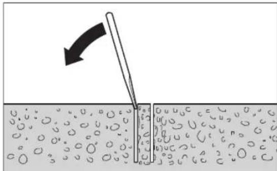
Erep Keph 6yPbInay KopoHkacbHa KaTbI opHaTbINFaH
60nca, JyMcak aFaunne Hemece nactK 6eWkeNeh
6yPbInay KopoHKacbIH KaFbIn, KePHdi 6ocatbHb3. KaKet
60nca, KepHdi TaKaNeh 6yPbInay KopoHKacbIHbH WETKi
6kaFbIHah Htepi WbIFapbHb3.
Hcyay:6yPbIay KopoHKacbiH KaTbI 3aTTapMeH KaKnaHbI3 (deopmaunay kayni bap)!
TexHnKaIbIK Kytim XHe KbI3MeT
KbI3MeT KepCeTy KHe Ta3anay
BapnbKxmbCTapdaH andbH 3neKtp KypanbHbH Xeninik aibpbH po3eKaadH bIfapbHbI3.
Kakcbi api cehimdi kymbic ictey yuih 3neKtp Kypanbl MeH KeJTeKiw TecikTI Ta3a YCTaHbI3.
Ticti peKahb (22) kHe 6yfbnay 6aHaHbHb (21)
6afttaybi 6etepin aapdaim Ta3a yCTaHb3.
Bypbnay uHHdeni (7) xMbIC COhHaTa3an an
uHb3. Keibip KAFdainapda 6yfbnay uHHDeni MeH
6yfbnay KopoHKacbHa (6) TO6acydah KopFaHbH 3aTTb ce6hi3.
Erep6aHnHaBc bIMbH aImactbpyKaKet 60nc, Kayinci3dIKTH TEmHeDeyIe KOJ 6epMey yuHIOcb Kymbc TEK Bosch KOMnHaHnCbI HeMece Bosch 3neKTP KypanDapbl 6oBbHwa eKInETTI KbI3MeT KepCteTy optaBkTapbHda Kypri3inyTnic.
Baftybiu bfpbikapkocmbuaaney (G cypin Kapa13)
YaBtEeKe 6aftTaybWbFbPbKTapTo3bn,
6aftTaybWbFbPbKTap Meh 6yFbNay cTAHnAcHbHIn
apacnDa 6oc apanKnnaDa 6onyb MyMkn. Ocb 6oc
apanktbXoO yin Eki 6aftTaybWbFbPbKtB
6ekitki Tekeiun (16) 6yniPihe KocblMa dAndey Kepek.
Eki aIbI bIbIraIaKaHbI (36) DeHbEK KInTneH (KInTe H17 MM) 6OcA TbHbI3.
Coad Kein Eki iiki aIbI bI bI bI bI bI (37) 6ipkeni TaTbI, 6oc apaIbIKbI a3aiTbHb3.
Eki antbIkyipnbI raiKaHbI (36) KaTadaH 6ypan 6ekitihia.
TacbImaIay
3πeKtp KypaBbI OPhaTbINFaH 6yPbInay cTaHHacBn CaTAYKaKoI0Fa 60NaBb. On yWIn 3πeKtp KypaBbH aHaNAtbH KpeCTTI (15) KEMeIMeH eDeHdIK TaKTafa KaPai 6apbIHwa
apb6ypaHb3 da, 6ypfbnay cTaHHacbHbH aydpblnybHa kOJ 6epMeH3.
Kayinc3 TacbMaJday yIiH 3neKtp KypaIbH 6yPbIaNay CTAHnHaH HbIFapbIH3. 3neKtp KypaIbOpHaTbIHaH 6yPbIaNay cTaHnAcBn Da teric 6eTeTacbMaJdayFa 6onadbl.
Kepek-kaapakap/Kocankb6nweKTeP
Apanbik TaKa 350 MM (GDB 350 WE) 2608 550 628
Bindek aanTepi (GDB 2500 WE) 2608550622
CzyHaycaHacbi(GCR350)2608550620
CzyKHHayCaKHaHcBHa apHaIraH 2609390391 TbIfb3dayblkKaKnak (GCR 350)
BekitkiXHHHaFbI:
-6eTOH yuH 2608002000
-kipniikanayyuih2607000745
BeToHaFa aHAnFaH an6oBenbepKinaHaFbl 2608002001
BaKyymdbikxHHaK 2608550623
BakyyMdbikxHHaKa apHaHan 2608550626 Tblb3daybiIpe3eHKe (GCR 350)
KbIJaAM Kblckblk KOHOHkacbi 2608598111
KbcbmdaFanfah cy 6a1b2 609390308
Service scule electric
Strada Horia Macelariu Nr. 30-34, sector 1
013937 Bucuresti
yKa3aHnHa 3a cnryphnoct
06u yka3aHnHa 3a 6e3onacha pa6oTa
PPEyIPEK-DEHNE
Ipooyete BCnKn npedynpexkdeHHy,ya3aHnHa,3ano3HaTe ce Cfhyprnte HTexHueckte Xapak
TePcTHKN, pNHOxKeH KbM eNEKTPoHHCTpymeHa. Ipo-nyCKn npn CnA3BaHTo H yaKa3aHnraT aNo-dOny MoRat da npeDn3BnKAT TOKOB yAp d Nnn TeKk TpaBMn.
CbxpnaHbAaTe Te3n yka3aHaHa cnpyhO macto.
N3noBaaHnT no-dOly TepMN "eneKtpoHCTpyMeHT" ce OTHacdo 3axpaHbAHn OT eNEKtpueckata Mpeka eNEKtpoHNCTpyMeHTn (cbc 3axpaHbau Ka6en) n do 3axpaHbAHn OT akyMynaTopHa 6aTePnEneKtpoHNCTpyMeHTn (6e3 3axpaHbau Ka6en).
PNEyPEXDEHNE!Korato H3non3BaTe eNektpoHnCTpyMeHTN,BHHaH Tp86Ba Da CneBate OCHOBHTe PpeHnCaHn 3a 6e0anacOCT,3a Da HamaHtpe PnCKa OT NoXap, ENEKTPnueckn yIap n nepcoHaHNO HapaHnBaHe,BKn. cneHOTo.Ppoetete BCNUK Te3n INHCTpyKUIN PpeDn Da ce ONNTBaTe Da H3non3BaTe To3n IpOdyKT H 3ana3eTe 3eN INHCTpyKUIN
Be3onachocHT ha pa60THoMRCTo
Pa3e pa60THO CH MCTO YHCTO HIO6pe OCBETHO. PaXbPnHHe NmTbMHn pa60THN MeTa ca npednoc-TaBka 3a HnDHTN.
He pa6oTeTe ceneKtpOnHcTpyMeHa B Cpea c NOBnWeHa ONaCHOCT OT Bb3HNKBaHe Ha EKcNIO3H, B 6IN3OCTdoLeChO3aIaNHM TeHOCTH, Ra3OBe Hnnpaxo06pa3Hm MaTePhAn. IIO BpeMe Ha pa6oTa EneKtpOnHCTpyMeHTte CeOTdEnrH NCKPn, KOITMOrTa Da Bb3PiMaMeHrt npaxoo6pa3Hm MaTePhAn Hn napn.
ДрьктЕпанСТРанчниИпаHa6be3O纳cho pa3ToHnHe,ДOKATOpa6OTNEcENeKTPoHHCTpyMeHTA.AKO BHNMaHHeTOBb6IeOTKIOHEHO,MOKeJa3aRy6Nte KOHTPOnaHADEnEeKTPoHHCTpyMeHTA.
Be3oNaChocT npn pa6oTa c eneKtpnueckn Tok
UeencbHa eNektpoHcTpyMeHTaep6Ba dae noXoH3a non3BaHHa KONTt. BnKakBcnyaHne Ce dOnycka H3MeHHe Ha KOHcTpkyHnTa Ha 9eNceNa. Korato paobnte cbc 3aHyEn He nEKeTpoypeH, He H3non3BaIte aanTepn 3a 9eNcena. IOn3BaHTo HaOpINHJIHN UeNCeHN KoHTaKN HAmJIBA pCKaOT Bb3HNIKBaHE Ha TOKOB ydap.
M36raBte OonHpHa TaNTo Bn Do 3a3eMeHn Tena, Hnp. Tpb6n, OTONNTENH ypeu, neukn XnaDnHHn. Korato TaNTo Bn e 3a3eMeHo, pncbT OT Bb3HKBaHe Ha TOKOB yap e NO-ToJAM.
PpeNa3BaTe eNeKtpOnHcTpymeHTa Cn OT bJxH BnaI. PpOHHKaHeTo Ha BOda B eNeKtpOnHcTpymeHTa NOBnJaBa ONaCHOCTTA O T KOK ynap.
He H3non3BaIte 3axpaHbuaa Ka6e 3a cen, 3a KOn ToTo He e npEbnH. Hkora He H3non3BaTe 3ax paHbaua Ka6e 3a npEhaCe, Ternehe Hn OTkauBa He ha enektpoHCTpyMeHa. PpeNa3BaTe Ka6ena OT HaPraBaHe, OmacnaBaHe, DoHp DO octpn Pb6oBe Hn Do NOBHXHN 3BeHa Ha Maunnn. Nobpehen nn ycukann Ka6e N yBEnuBaBat PnCKa OT Bb3NKBaHe Ha ToKOB yap.
Korato pa6oHTe ceneKTPoHcTpyMeH HABbH, H3non3BaIte cmo ydbNkntenHa Ka6eH, NOxOaHn 3a pa60Ta HaOTKpTO. H3non3BaHTo Ha yDbJXHTeN, npeHa3NaueH 3a pa60ta Ha OTKpTO, HamaJIbRa PNCa OT Bb3HNKBAHe Ha TOKOB yap.
Ako ce hana rna n3non3BaHTo Ha eneKtpOnHCTpyMeHa BbB BnaxHa CpeHa, n3non3BaTte npedna3en PpeKbcBa4 3a yTeHH TOKOb. N3non3BaHTo Ha npedna3en PpeKcbAch 3a yTeHH TOKOb HamaJIba ONaCHocTTa OT Bb3HNKBaHe Ha TOKOB yap.
Be3oapanenHaunHha pa6ota
BbTe KOHcHTpHaH, CteTe BnMaTeHNo DeIeBnTa CH N NoCTbNBAite PpeNa3INBO n pa3ymHO. He H3NO3BaTe eNEKTPoHnCTpyMeHt, KORaTO cTe yMoPeHH HnN IOB BnHnHETo Ha HApKOTuHn BEueCTBa, AnKOxO HnY noBnAun NEkapCTBa. EHN MnP a3ceHOCT np PaobTa C eNEKTPoHnCTpyMeHt MoKe Da Nm3aNoCneCTBne NkNIOHTeHnTO TeKKn HapaHbAHn.
Pa6oTe c npedna3BaIo pa6oH0 6nEknlo. BnHaH Hocete npedna3H ouHa. HocehTo ha noDxOJaI 3a NOn3BaHnI eJIeKTPoIHCTpyMeHT n H3BbPbWAHaTa DeHOC TIIuHn IpeJNa3H CpeIcTb, KaTO dXaTeIHa MaCa, 3dpaBn IIbTHo3aTbOpEH O6yBKn Cbc CTaBnIe Hpai- fep, 3aunTHa KacKa nnN Wymo3aRnyWntEn (aHTnPoH), HaMaJIra Ba PnCKA OT Bb3HNKBAHe Ha TpyOba 3IonoNyka.
M36BBAIe OAnHocTtA O BKNIOUbHe Ha eNekTPoHNCTpymEna No HeBNHMaHne. PpeIN Da BKNIOuHTe IeENCeLa B KOHTAKTA Hn Da NcTaBHe 6aTepeHra, KaKTo IN npn ppeHacHe Ha eNekTPoHNCTpymEna, ce YBePBAIte, Ye NcKOBnT NpeKbCbae nO3Hnna "N3KIOueHo". HocHeTo Ha eNekTPoHNCTpymEni C npbct Bbpxy NcKOBn NpeKbCBaHn NODaBaHTo Ho 3axpaHbAio HanpeXeHHe, DOKaTO NcKOBnT NpeKbCBaE BKNIOUeH, YBeINuBa OAnHocCTTa OT TpyDObN 3JOnONyKn.
PpeHnDa BKnIOHTe ENEKTPoHHCTpyMeHTa,ceYbepBaIte,ue CTEOTcPaHINNOT HrOe BCNUKNOMOHNHCTpyMeHTnRAeHHKNIOUObE.PMOUENHHCTpyMeHT,3a6paBeHnBaBPTAIO Ce 3BeHO,MOKe Da npuHHnTpaBMn.
M36HBAIte HeeCTeBHeHTe NOnOKeHHa TAnoto. Pa6oTe B Cta6nHNO NOnOKeHHe Ha TAnoto H BB BCEKIMoment NOdBpKaIte paBHObecne.Taka ue MoKeTe Da KOHTponHpate eJeKTPoHNcTpymEnTa No-dOpE nNo-6e30nacHO, AOK Bb3HNIke HeoeayKaBaHa CHTyaUH.
Pa6oTe c noxdoa o6neKn. He pa6oTe c nHPOKn dpexn Hn ykpaeeHH. DpbXte Kocata n dpxnTe cn Ha 6e3oNaCHO pa3cToHHe OT dBHXeHN Ce 3BHe. HpOKnTe dpexn, ykpaeeHHa, nbIITne KOCN MOraT da 6bDat 3axBaHaTH n yBleueHN OT BpTaHc CE 3BeHa.
Ako e Bb3MOXHO 3NON3BaHETO Ha BbHua acnnpaOnOHHa cHCTema,ce yBepBaHTe,te TRe bKIOUeHa NФHKUONHpaN3npaBO.N3NON3BaHETO Ha acnpauOnOHHa cHCTema HaMaJIBA pNCKOBETe,DbJIkaUe Ce Ha OT-DeJAAuCe npaP6oTa npaxOBe.
D6pOTo No3HbAHe H eNEKTPoHNCTPymeHTa BCneCTBHe Ha YecTa pa6Ota C Hero He e NOBoD 3a HamaJIbAHe Ha BHHMaHHeTo NpeHe6peBaHe Ha MepKHe 3a 6e3OpacHocT. ENo HEBHMaTeHNO DeIcTBHe MoKe Da npEiIM3BnKa TeKKn HapaHbHaHcMaO 3a qAcTn OT CeKyH-Data.
PnKnBO OTHoWeHne KbmeKtpOHcTpymeHTte
He npetobapbaTe enektpoHcTpymeHa. H3noJ3BaIte enektpoHcTpymeHTe cAmO cb6pa3HO TAXHOTnpedha3aueHne. Ue pa6oTte no-dO6pe nno-6e3onacHo, Korato n3noJ3BaTe noxOJaunr enektpoHHCTpymeHT B 3aadeHnO r O pON3BOJNTeIN dHaana3OH HaTOBAPBaHe.
He h3non3BaIte eNEKtpOHcHpyMeHT, qHTo nycOB npekcbaue noBpeH. ENEKTPOHcHpyMeHT, KOHTo He MOKe Da 6bJe H3KJIIOUBAH H BKJIIOUBAH NO ppeBnDEHH OIT pOIN3BOJNTeHaAHn, eONaceH TpR6Ba da 6bJe peMOHTnpaH.
IpeHn da H3BbPbATE KaKBHTO n da e DeHocTn no eneKTPoHnCTpyMeHTa,HaNP. NaCTPOBaHE,CMHa Ha pa6oteH HHCTpyMeHT,KAKTO N KORATO r np6Hpate, H3KIouBaHTe UenCeTa OT KOHTaKTA,peCn.H3BaXdaTe 6aTePnTa, aKO e B3MOxHO.Ta3H MApKa IpeMaxBa ONaCHOCTTa OT 3aDeEChTaBe HA eNEKTPoHnCTpyMeHTa NO HEBHIMAHHe.
CbxaHbAte eneKtpOnHcTpymEnTe Ha MeCTa, Kb-DeTo He Morat Da 6bDat OoCTnHnat O T Deua. He DoNyckaAte Te Da 6bDat H3NON3BaHN OT NHa, KOtO He ca 3ano3HATn C HauHn Ha pa60Ta C TAn H He ca npOeHn Te3n HcTpyKuH. Korato Ca B pbute Ha HeONTHN Notpe6HTen, eneKtpOnHcTpymEnTe MORat Da 6bDat N3-KJIOHTENHO ONACHN.
PnDpbjkaIte 1o6pe eNEKtpOHCTpyMeHTe cn n Akcecoapnte Hm. PnpOBepBaIte daHn NOBHXNHTe 3BeHa cyHKUONHPaT 6e3yKOpHO, daHn He 3aklnHBat, daHn HMa cUYneHN Hn NOBpeEHN DeTaHn, KOHTo HApYuBaBAT Hn H3MeHr T cyHKUINHe eNEKtpOHCTpyMeHTa. PpeHn Da H3NON3BaTe eNEKtpOHCTpyMeHTa, ce NOrpHXKeTne NOBpeEHN DeTaHn Da 6bDat pemOnTHpaHn. Mhoro OT TPyIOBHTe 3IonoJyKnCe DblXkAT Ha HeNo6pe NoDbpxKaHN eNEKtpOHCTpyMeHTn UpeHn.
PnDpbKaipepeeHHeHHCTpyMeHTBnHaHn Do6pe 3aTOueHN uHCTN. DObpe nOaIbpxKaHHe peKeu HnCTpyMeHTNC OcTpnpb6OBe OKa3BaT NO-MaIKo CbnpOTNBneHNE Hc BODAT No-NEKO.
H3no3BaIeeneKtpOHcTpymEnHTe,ONbHInTeHN Hte npncnOc6HeHna,pa6OTHe HcTpyMeHTn T. H., cbo6pa3HO HHCTpyKUHnte Ha pOn3BOHNTe. PpTOBa ce Cbo6pa3BAIte N C KOHKpeTHne pa6OTHN YCIOBnHa ONepaun, KOnTO Tp6Ba Da N3bHnTe. H3- NO3BaHETo Ha eNEKTPoHHCTpyMeHTn 3a pa3NCHNOT PpeDnEHeHTe OT pOn3BOHNTe PpINOJXeHn NOBnA Baa ONaCHOCTTA OT Bb3NHKBaHe HA TpyOBN 3NoONyKn.
PoiDbpxaTe DpBxKHe pBkoXBaTKte cyH, uCTn H HeomacneH. Xb3raBNTe DpBKKu PbKOXBaTKn He n03BoJRaB 6e3oNaChata pa6ota Ndo6poTo KOHTpOHa- He Ha eIeKtponHCTpyMeHa npu Bb3HKnBaHe Ha HeoayKaBaHa CnTuAua.
Toudbpkahe
DonyckaItepeMOHTbTHaeneKtpOnHcTpymeHTHe Bn Da ce H3BbPbBa cMoOT KBaHnHnUpaHH CneuaHnCTNcMoC H3NON3BaHETo HAOpRnHaHnPe3epBHN qactn. Ito3HnHaHH Ce rapaHTnpa cbxpaHnBaHe Ha6- 30NaCHOCTTa HaeneKtpOnHcTpymeHTa.
Ipeynpexdenn3a6e3onacnoc3a dhamahteho-npo6bHa maunha
Korato H3BpWBate np6HbAne, KOeTo H3NcKBa ynotpe6ata Ha BOda, npekapBaIte BOATA daNeUOT 3OHATApa6ota Ha onepatopa HnH 3N0N3BaIte YCTPOICTBO3a cb6npaHe HA TeuHOCT. TaKIBa PpeDna3HN MepKNoDbpxat pa6OHTa 3OHa Ha onepatopa cyxa I HamannBAt PNCKA OT ENEKTPNueckn yIap.
Korato H3mbnBaTe onepaun, np KoTo c6ueCTBy BA onaHocT peKeuHT akcecoap da 3acerHe ckpntn NOI NOBbpxHocTTa nPOBOHNu NOD HAnpEkeHne Hm 3axpaHbaun Ka6en, H3non3BaTte enektpoHnctpyMeHTa CaMo 3a H0JIHpAHnTE NOBbPxHocTH Ha pkoXBaTKHe. PIn KOtAKT Ha peKeunA kCecoap c npOBOHN KIOI HApeKeHne E Bb3MOxHO HApEkeHne To da Ce npedeNo Mo TaHnTE DetaiHa eNeKtpoHnCTpyMeHTa I TOBA Da npDeN3BnKa TOKOB ydap.
Hocete 3aunta 3a yuinte npn dhamanteho npo6bnaHe. H3naraheTo Ha uym Moxe da npuHH 3ary6ba Ha cny-Xa.
Korato 6yprnra 6nokpa, cnpe Ta HATNCKate HAOI Ny n3KnOuyete HHCTpyMeNTa. OTKPNIte npuHATA 3a 6nOKpHaTe Ho 6yprnra I a OTcTaPaHeTc c noxOJaM MEPKI.
Korato pectapthape dHaMaHTeHnI np6HBnE nHCTpymENT B DeTAla, npOBepTe dAn 6yprHtA ce BbtpTN CBO6OHO npEn 3anOuBaHe. Ako 6yprHnTa e 6nOKnPaHa, Ta MoKe Da He CTApTHpa, MoKe Da npetOBapn HNCTpymEnta HnMoKe Da npHHnDnHaMaHTeHn Inp6HBnEHCTpymENT Da Ce H3BAdn OT DeTAla.
Korato 3akpenbaTe noctabkata Ha nHCTpymenta 3a npo6BaHa c aHEkpn HΦHKcatOpn KbM detaIina, yBepHBaIe ce, ye h3non3BaHOTo anHEkpnpaHe MoKe da 3aDbpKa MaunHaTApn ynotpe6a. Ako DetaiNbTe cnabnnnopect, ankepbT MoKe Da ce n3ternn, Koeto ue
IOBBeI OOCBO6OxKaBaHe Ha NocTaBkata 3a HnCtpymeH-TaOT DeTnA.
Korato 3aKpenBate NoCTabKaTa 3a 6OpMaunHnTa C Ba KyyMHa NODIOXKa KBM DeTaN, NOCTABNte NODIOX KaTb Bbpxry TnAka, YHCTa H HeNopeCTa NOBbpxHOCT. He 3aKpenBaTe KbM NaHHnPAHn NOBbPxHOCTn KaTO NLOUKN KOMNO3HTHO NOKPHTHe.AKO DeTaNbT He e TnAbk, NIOCB NKnDObpe 3aKpeneH, NODIOXkata MoKe Da ce HTERIN OT DeTaN.
YBepete ce,ye HMaIOCTaTbUHO Bakyym npenHnNo Bpeme Ha npo6hBaHTo.AKO BaKyymt He eIOCTaTbUHO, NoIOXkata MoKe da Ce OCBO6OOn OT DeTaHa.
HnKora He H3BbPWBaHTe npo6hBaHe, aKO MaunHaTa e 3aKpeNa cMo C BaKyUmHa NIOLOXKa, OCBeH aKO He npo6hBaTe HaOny. Ako BaKyUmbT ce 3aYbH, NIOLOXKaTa Iue ce ocBO6OAn OT DetaiHa.
Korato npo6nBaTe npe3 cteHH nH TaBauH, yBepBaTe ce, ye 3aunTabate xopata n pa60Thata 30Ha ot pyrata ctpana. BypnraTMOKe da npemHe npe3 OTbopa nn OCHOBATA MOKe da naHe OTpyrata ctpana.
He H3NON3BaHTe To3H HnCTpyMeH 3a Inp6NBaHe Ha HNBTO HA rnaBata C nOdaBaHe Ha BODa. IpoHNKBAHeTo Ha BOda BeneKTpOHnHCTpyMeH Ta NobuBa OnaCHOCTTA OT TOKOB ydap.
M3non3BaIte NOxOJaN npH6Opn, 3a da oKpHeTe eBentyAnHO cKPHTNo IO NobPbXHocTt Tpb6oNpBOOHN, HIN CE O6bPHeTe KbM CbOTBeHTo MecTHO CHa6DHTeHNO dpyKeCTBO. BIn3aHTo B cbnpNKoCCHoBEHne C npOBoHNiNo HAppeJxHeMe MOKe Da npEdu3BnKa NoJxap N TOKOB ynap. YBpeJxHaTe HO ra3OpOBd MOKe Da DOBeJe Do EKnIO3N. NobpeJxHaTe HO BDOIpOBOD HMa 3a NocIeCTBNe rOJIem MaTePhaIIH N UeTN I MoKe Da npEdu3BnKA TOKOB ynap.
Pa6oTe c 6oyBKn CbC CTa6HHe nrgpAepe. Taka n3- 6yBaTe HapaHbAHH, KOHTo MoTaJa Bb3HNKHAT BCJeCTBnHa NOxNb3BaHe No IaBkNoJ.
HnKora He n3non3BaIte eNEKTponHcTpymenta 6e3 doCTaBeHHa DeΦeKTHOTOKOB 3aunTeH npeKbCBauch (PRCD).
06bPHeTe BHHMaHHe Ha TOBa,Ja HMa Xopa B pa6oTHaT3OHa HNHCpymeHTbT Da He Bn3a B KOHTaKT C BoDaT, KOrTo N3n3a.
HMKORA He octabTne eNEKTPOHCTpymEnTa 6e3 HAD-3Op,doKATO BbPTeHTo My He cIpe HantbHNo.BbptaIiTe Ce no HnepupeXeUHnCTpyMeHT Moat da npNHNr TpaBMn.
IpeHn da MOHTnpate 6OpMaunHaTa, crNo6e tceHda 3a npo6BaHe BHNMaTeHNO Hcnope yKa3aHnTa. IpaBnHToC rNo6RaHe e BaKHo 3a rapaHTnpaHe Ha 6e- 3yKOpHTo FyHKUHOHpAHe Ha CTHeJa.
PpeHn da H3non3BaTe 6OpMaunHnata, n3actonopete CnrypHNO KbM CTeHda. PnpNlb3BaHeTo Ha 6OpMaunHaB CTEHda 3a npo6bHe moKeJa npedn3Bnka 3aIy6ba Ha KOHTpO NaHn He.
3actonopraBte cTeHa Ha 3dpaba,paBa HOBbpxHocT.AKO cTeHbT 3a np6nBaHe MoKe Da ce npnnlb3Ba
HnCeIIOoe,6OpMaUNHaTa He MoKe Da 6bDe BoDeHa paBHOmePNO HcrypHo.
-Дрьктесхаразинкбелпбогмшнотанбетонpo pa3ctoHnne OTOHaTahpa6ota.Повpeни ИИУсукани Кбели YBeIuHaВat pIcKa OTb3HnKBaHe Ha TOKOB yap.
He npetobapBaIte cTeHa 3a npo6nBaH e H He To n3- non3BaIte 3a CbI6a nnckene. PpetoBapBaHTo nn KaBuHTo BbpxY cTeHa MoKe Da IOBeDe Do n3MeCTBaHe Ha ceHTbpa Ha TeKecTtMy Harope, B pe3yntat Ha KoETO Ta ce npoe6bPhe.
Korato He H3non3BaTe cTHe 3a npo6nBaHe, ro cbxpaHbAte Ha HeOcTbHnO 3a Deua Macto. DOnyckaTe CypeDa Pa60TnIuca, KOTo He Ca 3aNo3HaTH CHe Hn He Ca Pooen Te3n HnctpykUn. MaunHIne ca ONaCHN, Korato Ce H3non3Bat OT HeONHTn Iuca.
PpeHn da H3BpWbATE KaKBHTO n da e DeHocTH no CTeHda 3a npo6BaHe, npn npkebcaHe ha pa60ta n KOrato He ro H3non3BaTe, oChpyraBe TcEHda 3a npo6BaHe, kato BkIOuHTe 6nOKnpOBKaTa Ha MexaHH3Ma 3a NODaBAHe, 3a da npedOTbpaTHe H3MeCTBaHETo My No HEBHIMAHHe.
EnektponHCTpyMeHTbMOKe da ce H3non3Ba cAmo B eneKtpnueckmpexncBc3aunTHn npOBodHHnc n C DocTaTb4HNOHNHe
Bnarn3akpenbaite npna pa6ota cteHda 3a np6bHahe c nomoTa ha du6en, Bakyum (dobnHtEnho npncnoc6bHe) Hn KonoHa 3a 6bp30 3axBaUaHe, 3a da npedotbpaTne ppeobpuane Ha cTeHa c MoTHnpaHa dHaamHteOp6bHb 6opMaunHa 6opkoPoha.
BHHMaBaIte MapkyuHte 3a BOa, CbP3BaUte enemeHTKAKTO H BOOc6HpATEHNHT PbCTeH (OnblnHTenHO npncoc6neHHe) da Ca B 63yKOpHo cbctoHne. IpeHn Da 3anoHte pa6ota, 3ameHne NobpeHenn H3HOceHn DetaiHn. H3NJ3aHTo HA BOa OT qACTn Ha eNEKTPOINHCTpyMeHt aYBeNHaBa ONaCHOCTTa OT KOKOB yap.
Onncahne Ha npodykta n deHocTta

Ipooyete BHHMaTeHNO BCHKyn yKa3aHn H nHCTpykun 3a 6e3oNaChOCT. Iponyck npn cnaBaHeTo Ha nHCTpykUnte 3a 6e3oNaChOCT n yKa3aHnTa 3a paBota Moat Da hMat 3a nocLeDCTBHe TOKOB ydap, NOxap N/INN TeKKn TpaBMn.
Moi, HmaTe npedBnI 3o6paXeHnTa B npedHaT aact Ha pkoBOcTB0To 3a pa6ota.
PpeHa3NaueHne Ha eNeKtpOnHcTpymeHa
IpeHOMaDnAmAHTHo-NpO6NBHa 6OpMaunHa GDB 350 WE +GCR 350
HamaHTHO-npO6nBHa 6OpMaunHa
EeKtponHcTpyMeHTe npHa3Haueh 3a npo6nBaHe B MnHepaHm MaTePnaHn, KaTo 6etOH, CTomHaHO6eTO HnN 3nDaPnB KOMbHaunC dMaAMteHN 6OpKoPOHn 3a MOKpo npo
6nBaHe n npncnocobneHHe 3a noDaBaHe Ha B0da. EneKtpOnHnCTpymeHT MoKeJa 6bJe KOMBnHpaH c acnnpauoHa ype6a (BOOoc6bupateHn PpbTeH npaxocmykaUa 3a cyxo/MOKpo 3acmykBaHe).
Ionycka CE non3BaHeTo Ha eNeKTPoHnCTpyMeHTa CaMO B KOM6nHaunca CbC cTeHda 3a np6nBaHe GCR 350. Pa6ora
HaH HNBOTo Ha TnBaTa He ce pa3peWaaBa.
CTeHd3aDnAmaHTeHO-npO6bHNMaunHH
CTeHbT 3a DnMaHaTeHO-1pO6NBH MauHH e npEHa3HaueH 3a MOHTpaHe Ha Bosch DnMaHaTeHO-1pO6NBHtA MaunHa GDB 350 WE. C NOMoUHa Ha aadantopa
2608550622eBb3MOXHO CbIIO MOnHTnpaHTo HaJaMaHTHeo-IPo6NBHATA MaUNHa GDB 2500 WE.He ceDOnyCka MOHTnpaHTo HAdpynMaunHH.
C NOMOHTaHa HIO6eN CTHeBt 3a DnAmaHTeHO-IPo6NBH Ma- WHNMOKe Da 6bde 3axBaHAT KbM NOda INN KbM CTeHATA.
C NOMOHTa Ha Bakyum (DOnbHInTeHNO npncnoc6neHne) CTeHbT 3a DnmaHTeHO-npO6BHN MaunHH MoKe da 6bDe 3axBaHaT KbM NOA HN (C H3NON3BaHeTo Ha DOnbHInTeHNO OcHpyBaHe) KbM CteHa. 3axBaAe H TabaHa No3uHr He ce donycka.
C nOMOHTa Ha KOLOHa 3a 6bp3o 3axBaUaHe cTeHbT 3a dHaMaHTeHO-PIpOBINH MaHH MoKe Da 6bDe 3xBAHaT KbM IOna. 3axBaUaHe KbM cTeHa NnB TaBaHH No3uHr He Ce Donycka.
H306pa3eHH enEmeHTn
HomepnpaHTo Ha 136pa3eHHe Tc KOMnHOeHTN Ce OTHacdo H36paXeHHeTo Ha eEKeTPOHHCTpyMeHtA Ha CTeHda Ha rpaDnHte CtpaHnU.
DnamaHTHO-npO6NBHb 6OpMaUNHa
(1) ABToMaTHuEnIpeJa3eHn3KJIIOUbATEn (PRCD)
(2)Пусковп配电ьсау
(3)превклочьатела петдынгte
(4) Lluyep3aBKNIOUBaHe KbM KpaH
(5)CnnpaTeHKnpaHa3BaBogTa
(6) BopKopoHa
(7) Bān
(8) MexaHbM 3a 13BaXdAne Ha 6OpKopoHata
(9)Дрьхka3a HOCHeHa 6opMaunHnHaTa
(10) BnHToBe Ha npbXkKaT3a HocHe Ha 6OpMaunHnHa
A) N3o6pa3eHHTe Ha 0hrypnte HONCAHNTe DOBnHNTENnn NPNCNOc6NEHn HE ca BKNIOUeHN B cTaNAPTHATA OKOMNNEKTOBA HA ypea. N3eepnATEEN CnBCK HA DOnBnHNTENHtpe PnHCNO6NEHn MOxETe DA HamePte CBOTBEHO KATAIORA HH 3a DoBnHNTENn PNCHNOC6NEHn
CTeHd 3a DnHaMaHTeHO-tnpO6NBm Maunnn
(11)Дрьжka3aHOCHeHaCTeHda
(12) BnHTOBe HaIpbXkKaTa 3a HocHe HaCTeHdA
(13) Cka 3a HaKloHa Ha OTbopa
(14) EKcueHTpIKOB uHΦT Ha rHe3dTo 3a 3axBauahe Ha MaunHa
(15)Bbptraa cepbkoxBatka (nOJIpaHa noOBbpxHocT)
(16) Cnnpaucka
(17) KaIInauTa raiKa 3a peryIinaPeHa Ha KaIOHa Ha oT-Bopa
(18) BnHT HaJIbEnata
(19) OchOBHa nnoya
(20)BoOocb6npaTeNeH npbcteH
(21) KonoHa
(22)3b6uataaHa
(23) BnHTObe 3a MaunHHnA aanTeP (M8×20)
(24)Пптнсkaиnpужннзаадаллета
(25) AДантор
(26)3aBnKbAio KoneNo
(27) THe3Do 3a eJekTponHcTpymENT
(28) Μιδηλα 3a δεντικαλήθο σρημεπτίραη
(29) Pa3dJIeTIeHnHa pIaCTHnHa
(30) BnHTObe 3a pa3dennenHa nactHna (M8×45)
(31)Припсскаши ружнни Ha pa3делпелнота nlactnHaA
(32)ДIO6eN3a3IaIapn/ДIO6eN3a6eTOH
(33)БьрзэateratehenшнндEN
(34)Kpuiuata raikha 6bpi03aterateHnHnHnA
(35)O6Tgaa npyKnHa Ha BDOc6bnpaTeHnna npbcTeH
(36) ⅢecToTeHHaIaKaHa HAnpaBnBaTaTpoNka
(37) BnHT C rnaBa C bBtppeWeH WeCTOCTeH 3a HAnpaBnBaAata pOJa
A) N3o6pa3eHnTe Ha 4hrypHTe H onncAHte DoNbHnHTenHH npCNOC6BHe Hc Ca BKNIOUeHN B CTAHApTHa OKOMNEKTOBk Ha ypeHa. N3eepNaTeHc CnCbK Ha DOnbHnHTENHtpeNcNO6BeHMeMOXeTe Da HamePHTe CbOTBtHO B KATAIora Hn 3a DonbHnTENH npCNOC6BHeH.
TexHHueckn daHHN
IpeHocMa dHaMaHTHO-npO6nBHa 6opMaunHa GDB 350 WE ^+ GCR 350
| Диаманно-пробнва Борmaшина GDB 350 WE | |
| Каталожен Homep | 3601 A89 9.. |
| Hоминална консуmpрана моцноct | W 3200 |
| Полеэна моцноct W 2300 | |
| Hоминална скорост на Вьртоны | |
| -1. П dedавka min | -1 420 |
| -2. П dedавka min | -1 820 |
| -3. П dedавka min | -1 1250 |
| Диаметер на CB畴лOTO | |
| -1. П dedавka mm 165-350 | |
| -2. П dedавka mm 80-160 | |
| -3. П dedавka mm 55-105 | |
| Гизdo 1 1/4" UNC | |
192|Бьлгарский
| ДиамаHTо-пробинha Бормшинha GDB 350 WE | |
| Мakc. налгае на ВODита систema | bar 3 |
| Маса сблacHo EPTA-Procedure 01:2014 | kg 11,9 |
| Клас на зашита /I | ⊕ |
| Размери (Вкlioочtenho eelen- MeNTITE, КОТTO могатда ce демонтурat) | mm 534 × 142 × 168 |
Dahnhe Baxat 3a HOMHnHaHO HApexeHHe [U] ot 230 V. PnO tKNOHbaaI CE HApexeHHe I npn CieuNpHn3a OteiHH NtB/HeHH TESd HANMOTar aBaHPaT.
| Стэнд за димаHTeHO-пробиВн машени | GCR 350 |
| Каталожен Homep | 3601 A90 200 |
| Размери | |
| - Височиа mm 955 | |
| - Широчиа mm 323 | |
| - Дыбочиа mm 388 | |
| Мамс. размери на боркорoga | |
| - Димаевр mm 300 | |
| - Димаевр с раздени滥 пл actina (29) | mm 350 |
| - Димаевр с вodocьбира- тelen пьстен | mm 202 |
| - Дыжниа mm 530 | |
| Xord, масc. mm 580 | |
| Мамс. работен xord. mm 550 | |
| Маса съласno | kg 12,6 |
| EPTA-Procedure 01:2014 |
Hhopmaa3a n3buaBn yM
CTOHOCHTHe HA EMUCHN HA WYM CA yCTaHOBEHN CbrrnCHO EN62841-3-6.
PaBHHIeToAHaTReHepnpaHmIyMOTEnEeKTPoHCTpyMeHTa 0bHKHOBeHo e: paBHHIe Ha3BykoBTo HAIraHe 96dB(A); MoUHocHa3Byka110dB(A).HeonpeJeHecrK=3dB.
MHHMaJIeH BaKyM: 80% (-800 mbar)
3a 3axBaAHe C BakyM NOBbpxHocTt Tp86Ba Da e rnaika paBHa. N3noI3BaHTo BbpyMa3nIk HnN 3nIapn He ce donycka.
Cne KaTO ce NOnyU BakyU M Donpe He HNBENpaUte BHTOBe (18)NeKo Do OCHOBaTa, 3a Da 6bDe Bpb3KaTa TBbpDA n yNtHnTeHNHrT npCTeH da ce paTobApu neko. B npOTBEN Cnyau CTehbTe 3axBaHaT enactuHcMo ppe ynbT HnTeHNH npCTeH.
3a MOHTnHaTeHa BakyMHaTa NOMHa BakyMHN KOMnJIeKT Ha Bosch npoTeTe H Cna3BaTe TexHHe pkoBoOCTBa 3a ekCnloataua.
CTPNKTHO Tp86Ba da ce cna3BAt yka3aHnra 3a 6e30-nacha pa6ota Ha BakyyMHaTaNOMNa H KOMNKeKTA 3a BakyymHO 3actonopbaHe!
3aKpenBaHe c KOnoHa 3a 6bp3o 3axBaUaHe (Bx.ΦnR.E)
Moxete da 3axBaHeTe CTeHa 3a npo6nBaHe C nOmoTuHa KOHOHa 3a 6bp30 3axBaUaHe Ha Bosch (npHnAdJeKHOCT) MEXy NDo HA TabHa. Dnna30HbT 3a 3axBaUaHe e MeXy1,7m H3m.
IocTabeTe eHnHa Kpa Ha KOHOHa 3a 6bp30 3axBaUaHe BbpyOcHOBHATA IIOuHa HA CTeHda. OOnpHata NOBbpxHOCT Ha TaBaHa 3a DpyrHa Kpa Ha KOHOHa 3a 6bp30 3axBaUaHe Tp8BaJa e DoctTaBHyO CTaBnHa H da He e Xlb3raBa.
3a 3actonopraBaHe Ha KOIOnHaTa 3a 6bp3o 3axBaUaHe npOteTe HcneBaiTe yKa3aHnraTbPbKOBoCTBToH 3a EKcnnoatau.
HbBnnpaHe (he ce oTHac3a 3aactOnopBaHe c BaKyym)
3aTeHHeTe,peCn.pa3BnTe BCEKNOT HNBEnPaUHTe BnHToBe(18),DOKaTo N6benaTa(28)(PnBepTKaENMOHTaK) ceIeHTpnpa.
CneToBA3aXBaHeTe 3npaBO CTeHda 3a np6bHaHe CIO6eIINI KOnOHa 3a 6bp30 3actOnopBaHe.
NoctabrHe/3amHa Ha 6OpKopoHata
PpeHn da n3BpWBate KaKBHTo n da e DeHHocTHn no CTeHda 3a npo6BaHe, npn npKeBcBAHe Ha pa60Ta N KOrato He ro H3non3BaTe, oChrypaBte CTeHda 3a npo6BaHe, kATO BKJIOHTe 6NOKIpOBKaTa Ha MexaHN3Ma 3a NoDaBaHe, 3a da npedOTbPaTHe N3MeCTBaHETO My NO HeBHIMaHHe.
TocTabaHe Ha 6opkopoHaTa
PpeHn da nocTabte 60kopoHata, npoBepe. H3- non3BaTe caMo 60kopoHn B n3pAHO cbCTOHHne.
IobpeHn Hn DeOpMnpaHb6opKoPOn MoTa npeDn3BnKaT onaChn cnTuaynn.
Ipei Da noctabite 6opkopoHaT, r NouchteTe. CmaKeTe IeKO pe36ata Ha 6opkopoHaT a nn HapbckaIte C npOTn-BOKOP03HOHe CNpei.
HabnTe 1/4"UNC6opKoHa(6)Bbpy Bana(7).
YBepete ce, ye 6opkopoHaTa e 3aXbaHaTa 3paBO.
HenpaBnHIO Hn Hn Heo6pe 3axBaHATn 60pKOpOnn MoT a da ce pa3BnT NO BpeMe Ha pa6ota Da Bn 3actpaWat.
DemOHTHpHaHe Ha 6OpKoHata
Pn3aMaHa ha 6OpKOpOHata paOteTe c npEpa3Hn pbKaBn. Pnp npDbJnxHeHa paOta C eNeKtpoHcTpyMeHa 6OpKOpOHata MoKe Da ce Haropeu.
Pa3BnTe 60pKOpohata (6) c raeueH KIOU (pa3Mep 41 mm). Ipi TOBa 3aIbPkaJIte KOHTpa, KATO 3axBaHETe BaIa (7) 3a CKOCEHITe NOBbPxHOCTN C BTOH raeueH KIOU (pa3Mep 32 mm).
MexaHn3MbT 3a N3BaXJaDaHe Ha 6OpKopoHata (8) 06NeKuAba pa3xla6BaHeto Ha 6OpKopoHata (6).
BkHIOUbaHe Ha BOHOTo OXnAaHa
Ako no BpeMe Ha pa6oTa 60pKOpOHte 3a MOKpo np6nBaHe He 6bDat OXlaKaHn DOCTaTbUHO, DnAmAHTHIne CeRMHTN MoTAt Da 6bDat NOBpeDeHH INH 60pKOpOHta MOKe Da 6NoKnpa B OTBopa. 3aTOBA pnp MOKpo np6nBaHe BNHaRn CneTe OXlaKaDaHTo Da e DoCTaTbUHO.
Pn pa3wnpraBaHTo Ha cbueCTbByaU OTbOp Tp86BaJa 6bJe 3aTbOpEn CTapatenHo, 3aJa 6bJe OcnpyeHO DoctaTbHuO OxnaJdaHe Ha 6OpKopoHata.
N3noI3BaHHTe Mapkyu, cnnpaTeHH KpaHOBE Hn DpyTH DoBbHHTeHH npncnocO6NeHH He Tp8Ba da npevat Ha npo6bHaheTo.
3aTbOpTe cInpaTeHnna KpaH 3a BOnaTa (5).BKnIOUeTe 3axpaHbAunMapKyu 3a BOJa KbM Uyepa (4).Bb3MOXHO e 3axpaHbAHeTo C BOna OT Mo6nHe H OBeH pe3epBoAp (DOnbI
HHTeJIHO npncnocobJeHne) nIOT ctaunohapHa BOOpnoBODHa HCTaJauJy.
3a da ynaBTe H3nH3aUaTa OT OTBopa Boda np MOKpo npo6bHaBe,ce HykdaTe OT BODocbupaTehen PpCTeh N ppaXOCMykaKa 3a MOKpo/Cyxo 3acMkyBaHe (He ca BKNIOueHN BOKOMNNEKTOBkata).
MOHTnpaHe Ha BOOc6bHpAteHnHnI npbCTeH KbM H3CMyKBAHeTo Ha BOa(BK.ΦHr.F)
BodocbnapaTeHHnTnpbCTen(BK.,DOnbHHTENn npncnoCobneHn/pe3epBNuactn",CtpaHnca196)e npebnnd3a ynoTppeBa cbc CTehn 3a DnAmAHTeHO-npOsbHN MaunHnGCR350NnMaAMaHTeHO-npOsbHBMaunHa GDB 350 WE.
H3peXeTe B yNtBTHIeHHa Kanak OTBop 3a XeNaHHaMnA MeTbP Ha CBpeDlOTo.
BkapaTe HaTgAaTa npyKHa (35) Do yNop B O TBopa MeKdy NIOOBaTnAACTIna (19) IN KOLOHATA (21).BHNMABaIte 3aBbPTHaTata qact Ha o6TgAaTa npyKHa da coun HADony. IocTabete BOOcB6HpateLnnn npbCTeH BHyXHa Tno3uHn DOnpete HaTgAaTa npyKHa DO onOpHtE TOUKN Ha BOOcB6HpateLnnn npbCTeH. (E3uHETa BA Kpaar Ha HATraaTa npyKHa cLyKaT 3a NOBdHrHe Ha npyKHaTa HArope.)
Blaqapene Ha cnilata Ha hatraaata npkyna ynnbThe Hneto Ha BOOc6bnpateHnHT npbCTeH ce npntNcKa KbM OCHOBATA N3aeDHO CbC cb3daBaHH OT npaxOCMykaKATA 3a MOKpo/cyxo 3acMykBAHe BaKyum pedOTpTaBA IpOTnuA HeTO HA BOJa.
BoOc6bupateHnHHT npbCTeH moKe da 6bJe 3aBbptAH CnpA Mo npNTCKaun npbCTe, 3a da MOKe 7uCyepbT da 6bJe NOCTaBeH B JekHaTa N03uN (Hanp. 3a NoD6pbAbe Ha OTBeKaHaTe HbOda Tn Pn P06BaHe Ha XOpNtOHn OTBOp). 3a cEnTa OTBopTe 3aTgauN MexaHn3bM Ha npNTCKaun npbCTeH, 3aBbPteTe BOOCbupateHnHn npbCTeH Do JekHaTa N03uN I OTHoB 3aTBOpTe 3aTgauN MexaHN3bM.
Pa6ota ceneKtpoHcTpymeHTa
PpomHa Ha HAKNoHa Ha npo6HbAHnO tBOp
Pepn H3BpWBAHe Ha KaKBTO N Da e DeHOCTH NO eNekTPoHHCTpyMeHTA N3KNIOVAIte UeNCena O TaxpaHBaata MPexa.
BnHaH CneI npOMHa Ha HAcTpOuKHTe OTHOB 3aTraNTe BCHKN BNHTOBe.
Pa3BnTe KaNaaTaTa RaKa (17) c BbPraTa Ce pbKoXBaKa (15).
C nOMOuTa Ha cKaNaTa 3a bBn Ha npo6BaHe (13) HactpoTe JeHaHn BaHn Ha KaIOHa Ha CTeHa. 3a ToHTo HAcTPOBaHcNeTe CtePekata Do KaIInaatata RaKa (17).
3aterheKaannayataTaraKa(17)C BBpTaataCe pkoBbATka(15).
Donycka ce non3BaHeTo Ha cTeHda 3a npo6HbAe caMo aKO KaIINaayata raKa (17) Ha npncnocObeHneTo 3a HAKNAHHe e 3aterHata.
IyckaneBekcnnoataa
Cb6pa3aBaIe ce c HappeXeHneTo Ha 3axpaHbAuaTaMpexa! HappeXeHneTo Ha 3axpaHbAuaTa MpeXa Tp8bDa CbOTBeTCTBa Ha DaHHnTe, H3NnCaHN Ha Ta6eKnata Ha eNEKtpOHnHcTpymEHTa.
PpeH3anOuBaHe Ha pa6oTa ce KOHCyTNHpAte COTROBOPHHCTPONTeHnHHKeHep, apXHTeKTHmCpbKOBOCTBTO Ha cTpONTeHHnOBtE. Ipepa3BaIte apMnPOBkCa Camc Pa3peHneHa cTpONTeHnHHKeHep.
Pn npo6nBaHe Ha npoxOHN OTBOpN B CteHn HnB NOda 3aDbJnxHTeHNO npOBepBaIe DaH N DpyrTO NOMeueHHe HMa npueeu nppeMTh. OOrpaHcyTe DoCTbna DO MxToTo Ha npo6nBaHe N OCHypTe No npoxOAn HaHH JpTo Ha npo6nBaHn OTBop CpeUy H3npaHa.
Функунанен TeCT Ha aBToMaTHuHnI npeDna3eH nKIOUbATEN (FI-npeKbcBaU)
BnHaH npEn 3anOuBaHe Ha pa6ota npOBepBaTe npaBnHTo fYHKUHOHPaHe Ha aBTOMaTHNn npEJa3eH H3KnIOuBaTeN (Fl-npEkbCa) (1):
-HaTnchete TEST 6yToHa Bbpyx ABTOMaTHHnI PpeiNa3eH nKIIuOvBaTeI (FI-npekbcBa).YepBeHaTa KOHTpOHa naMa yracBa.
-HaTnchete RESET 6yToHa.CneT TOBa eEnKtpOHCTpyMeHTbT Tp6Ba Da MoKe da Ce BKnIOH.
Ako KOHTponHaTa IaAMNa He yrache, KORaTo HaTnCHete TEST 6byToHa, a AKO OTHOBO Yrache npu BkIIOUBaHe Ha eNEKTPoHCTpyMeHTa, Tp8Ba Da npedaTe eNEKTPoHHCTpyMeHTa 3a npOBepKa B OTOpN3npaH cepBn3 3a eNEKTPoHHCTpyMeHTn Ha Bosch.
Ako aTOMaTHUHnI pEiHa3e H3KlnuBAten (FI-npKbCBAu) eNoBpeDeH, He ce IOnycka eEnkTpOHnHCTpyMeHTbT da 6bJe NoJ3BaH.
BknlouBaHe
HaTHNCHETe RESET 6yToHa BbPxy aBTOMaTHNuHnI ppeDna3eH nKIIIOuBaTeN (F1-npeKbCBAU) (1).
HactpoKTe cnpaTeHNHa KaH 3a BODaTa (5) Ha npotnuaHe.
3a BkIOUBaHe Ha eNEKTPoHnHCTpyMeHTa NOCTaBeTe NyCKOBIN PpeKcbCaB (2) B N03N1A 1.
N3KJIIOUBaHe
3a n3KIOUbaHe Ha eNEKTPoHnCTpyMeHTa NoCTaBeTe NycKO Bn PpeKcbau (2)BnO3nua 0.
3aTbOpete cnpaTeHnKpaH 3a BOData (5). Cnei npNKIIOUbaHe Ha pa6Ota I3KNIOUeTe Uyepa (4) OT BODONPOBHDHa TcStema. OToBopTe cnpaTeHnKpaH (5) H3TOUeTe OCTaHAnATA B rIaNBaTA BODa.
OrpaHueHne Ha NycKOBnTOK
EneKtpoHHTo ynpaBHeHHe ha eNkTpOHNCTpyMeHTA ocNrypBa INaBHO BKJIOUbaHe Ha eNkTPODBratEnI n Taka npedOTbpaTBA TBbpDe rONM NyCKOB TOK.
3aunTa cpeu noBtOpHo BkIIOU4BaHe
3aunTaTcpeuNOBtOpHO BKIOUBaHe npedOTBpaTBA He KOHTpOINpHaTO BKNIOUBaHe Ha eNEKTPOnHCTpyMeHa cIeI pKeBcBaHe Ha 3axpaHbAteo.
3a NOBTOPO NyCKaHe HaTCHete RESET 6byToHa Bbpyx aBtOMaTHHnI npEpa3eHnKIIouBaTeI (1).
IocTaBeTe CnED TOBA NcCKOBINpeKcbBaU (2) B nOnOKeHne H3KNIOeHO IN CnED TOBA OTHOBBKNIOueTe eNEKTPoHnCTpyMeHTa.
PpeBapHTeH OYCTAHOBBAHe Ha CKOPoCTTHa BbPTHe C PneBKNIOUbaTeIa 3a PpeBaKITE (3) MoT a Da 6bDat N3bpaHn Dba dnaIanaOHa HA CKOPoCTTHa BbPTHe.
IpeaBKeTe ce npenopbUbaT 3a CneHnTe DnaMeTpHa CBpePaTa:
-
- npedabka: 165-350 mm
-2.npeaBka:80-160mm
-3.npeaBka:55-105mm
- npedabka: 165-350 mm
Yka3aHn3a pa60Ta
Pepn H3BpBaHe Ha KaKBHTO Ha da e DeHocTH No eNekTPOHHCTpyMeHTa N3KNIOuBAIte UeNCeJa OT 3axpaHbAaTa MPexa.
Pn npo6bHahe pa3BnBaIte cnpaKaTa (16)ToKOBa,Ye BbpTtata Ce bpKOXBAtka (15)da MoKeJa ca De BVKnHneko. 3a da npedotBpAInTe HeKoHTpOlnpaHO nadaHe NaeKtpoHHCTpyMeHa, Pn TOBa DpbXte BbpTtata Ce bpKOXBtKa.
3anouhe Te npo6BaHTo Ha nBpBa npedAbKa c OpraHueHaCKOpoc HbBpTeHe,doKato 60pkopOnHa 3aoUHe da CeBp3Ba,6e3 Da Bn6Pupa.CneTobA pIn Heo6xOImocTnpEKBIOUeTe HA BTopa nn TpeTa npedaBka.
Pn npo6BaHe perynpaTe Cnata Ha nptnckaHe cbo6p3Ho npo6BaHHMaTepeHAn. Pnp6BaIe CnoTOnHHaCnaHa nptnckaHe. NepnoDnuHO OTdpNBaTe bOpKOpohata neko Haa, 3a da MoKe da Ce otDeni OT cerMeHTne Hatpyanata ce npn npo6BaHeto ytaKa.
C Bbptraata cpe bkoxbatka (15) cnyche teneKtpounHcymeHTa do jekanaHata dbnbouHHa Ha npobnBaHe. CneTobTa3aBbPTe IocTa HAO6paTHO,doKATO 6OpkopoHaTa H3ne3e OTOTBopa HnBnHO.
3a da oocnHete MaKcHMaJIHO Bb3MOxHHpa6oTe XOD, Tp8Ba da otCTpaHbATE cbpuEHNHaT O6pKOpOHata, Ko rato Ta 6bDe 3aNbIHeHa H3qAno. CneToBA OTHOBo BKapaiTe 6OpKOpOHata BOTbapa H np6hnte Do MaKcHMaHata Dbl6OuHa.
IpeJna3eH cbeHnHnTeI
Ako 60kopoHaTa ce 3aklnnnn nn 6boknpa, 3aBmKBaHTo Ha Bana ce npkecbcBA. B TaKB CnyaB BeHnara n3knOyete eNEKTponHCTpyMeTA, 3a da OrpaHnHTe N3HOcBaHTo n nperePraBaHTo.
Ocbo6oTe 60pKOpHaTa Upe3 3aBbPtaH c nOxOJa rae- YEN KIOU HAIBO HAIJCHO. Pn TOBA H3BaTe BHNMaTeIHO eNkTPOHnCTpyMeHTA OT npObuHn OTBOP
PpeNa3BaHe OT npetOBapBaHe
Ako 6bIe npemHnat npaTbHa npetobapBaHe, enektpoHCTpymehTb 3anoBa da npuncpa uYbCTBntenHo. HamaNete ci
IaTa Ha npHTnCKaHe, Taka ye eNeKtpoHHCTpyMeHbT da 3apa-60TH OTHOBO HOPMaJIHO.
Ako cnIaHa npHTnCKaHe He 6bIe HaMaJIeHa, eNEKtpOHCTpyMeHbT ce H3KNIOyBa. BeHara cneI TOBa MoKeTe Da BkIOuHTe OTHOBO eNEKTPoINHCTpyMeHTa, HO Tp8Ba da pa60Tnte C NO-MaIKa CNHa Ha npHTnCKaHe.
OCTpaHbAbe Ha JdpoTo Ha OTbopa
Octabete BOData da npodbnn da teue n3BecTHo BpeMe cIe cnipaHe ha npobnBaHeto, 3a da OTMne HATpynAnite ce Mekdy bopkopohata n npoto Ha OTBopa 3aMbpcBaHna.
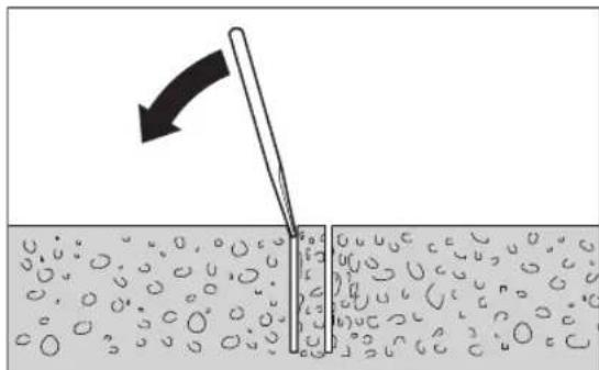
Ako npoHa OToBa ocTaHe 3aXbHaTo B6pKOpohata, To OCbo6OeTe, KaTo yDpTe C MeKO DpBeHO HnPiactMacob Tpyne No6bpKOpOHata. PnH Heo6xOAnMoCT NtIaNackaJte AdoTO, KATO npeKaPaTe JeTBA Hn WnNlka Ppe0nOnaWkata Ha6bpKOpOHata.
Yka3aHHe: He ydpIe 6opkopoHaTc TBbpHn ppeMeTH (onacHOCT OTeΦoPmnpaH)!
PoaDbpXaHe n cepBn3
IopdbpxaHe n nounchBaHe
Pepn H3BpUbaHe Ha KaKBHTO H Da e DeHOCTH No eneKTPoHcTpyMeHa N3KNIOVAIte UeNCena O TaxpaHbauata MPexa.
3a da pa6oHTe KaueCTBeHO 6e3onacHO, noDdbpKaaTe eNEkTPOHnCtpymeHTa H BeHTnlauHOHHTe MyOTBOPN uCTH.
PoiBpKaIte BnHaHn UcHTN 3b6Hn rpe6eH (22) n HapabJIbaaNTe NOBpXHOCTn HA KOLOHATA (21).
Cnei npknHueBaHe Ha pa6ota NoHCTe Bana (7).IpeHIOuHNO HAnpBcKBaTe Bala N 6OpKopoHaTa (6) c IpOTHBOKOPO3HOHEn CnpE.
Korato e Heo6xOIma 3amHa Ha 3axpaHbuaa Ka6en, TPr8Ba da ce H3BpuIN BOTOpn3npaH cepBn3a eNEkTponHCTpyMeHTn Ha Bosch, 3a Da ce 3ana3n HbTO Ha 6e3onacHOCT Ha Bosch eNEkTPOHHCTpyMeHTa.
Doperynpane ha Bodeuinte poKn (Bx. Hr.G)
CTeueHHe Na BpeMeTo HnPaBnBaUHTe PONK MoRat Da ce H3HOcT N Da Bb3HnKHe NyfT MExy PONKte N KOHOtA.3a da npEmaxHete NyfTa, Tp8Ba Da perynipate DBeTe HapBnBAuN PoKN O TcPaHATA Ha CnnpaKata (16).
Pa3BnIte DBeTe WeCTOCTeHHr RaIKH (36) C raeuen KInou (pa3mep 17 mm).
CneTOBa3aterHepePABHomepHO DbTa BnHTa C rnaBn C BbTpseHWeCTOCTe (37),DOKATO NyΦTbT H3Ye3He. OTHOBo 3aterHeTe DBete WeCTOCTeHHrAikn (36).
TpaHcnopTpupahe
MooTe Da octaBHTe Ha 3eMaTia NOCTaBkata C NOCTaBeH eNEKTPOHCTpyMeHT.3a cIeTa 3aBbPte TE eNEKTPOHCTpyMeHTa CBpTAAca Ce pbKOXBAtKa (15) KOJIKOTO ce MoKe No-DaNeu No NocOka Ha NODoBaTa PnAcTHHa, 3a Da npeDoTBpaTite npeOpbuahe Ha CTHeJa.
3a cnhypno tpaHCnOpTnpaHe cBaJIte eneKTPoHnCTpyMeHa Ta OT NoCTabKaTa. MoKeTe Da TpaHCnOpTnpaTe no paBHN NOBbpxHOCT CteHda C NoCTaBeH eneKTPoHnCTpyMeHT.
DOnbHHTeHH npncnoc6neHH/pe3epBHu actn
Pa3dienTeHa nactHa 350 mm 2608550628 (GDB 350 WE)
MaunHeH aanTOp (GDB 2500 WE) 2608550622
Bodocbupatehen npbcten (GCR 350)2608550620
YnblthnteHekanak3aBDOcb6bpa- 2609390391 TeHHn npbcTeH (GCR 350)
KoMnIeKT KpeIeKHi eneMeNTH:
-3a6eToH2608002000
-3a3ndapn2607000745
KOMIIeK TIO6eHn 3a 608 002 001
KOMIIeK3aBaKyMHO3aToNOpBaHe2608550623
YnblTHTeHa rMnka 3a BaKyMeH 2608550626 KOMnEKT (GCR 350)
KonoHa 3a 6bp3o 3acToOpBaHe 2 608598111
Pe3epBoap 3a B0da noD hannrane 2609390308
Ppaxocmyka3a mokpo/cyxo noohCTBahe GAS 35MAFC
Ppaxocmykaquka 3a MOKpo/cyxo nouictBahe GAS 55MAFC
KnneTcKa cnx6a H KOHCyntaun OTHOCH ynoTe6ata
CepBn3bT ue OTROBOpH a Bbnpocnte Bn OTHOcHPOmoHTn HnoDpBkKa hA 3aKypeHHo T BAC npOyKT, KaKTo n OTHOC HO pe3ePBn qactN. POKOMNoEHTHn QeTpExn NnHΦopMaZu 3a pe3ePBnTe qactn ue OKPneTe n Ha: www.bosch- pt.com
EkntnoKohcyntaun OTHOCHOyntpe6ata Ha Bosch ue Bn nomorhe C yD0BONCTBne npn Bbnpocn 3a haWnte npOdykTN HTEXHNTe akcecoapn.
MOnn, npN Bbnpocn H npn NopbUbahe Ha pe3epBHN qactH BnHar nocOuBaIte 10-uapeHHa KATAIOXeH HOMep, H3nnCah Ha Tabekata Ha ypeda.
BbIraHna
Robert Bosch SRL
Service scule electrice
Strada Horia Macelariu Nr. 30-34, sector 1
013937 Bucuresti, Romania
TeN.:+359(0)70013667(BbIraPcKN)
a c + 40212331313
Email: BoschServiceCenterBG@ro.bosch.com
www.bosch-pt.com/bg/bg/
BpaKyBaHe
EnktonHCTpymENTte,CTeHDoBete 3a np6BaHe,OnbHnHTeHNHe pncnocobene H onakOBKe Tpa6Ba da 6bDatnpaedeHH 3a ONoN3OTBopraBaHe Ha cbDbpxkaunTe ce B TaXBTOpuHH CypOBHH.

He 3XbPnIe enktpoHCTpyMeHT np6IOBHTe OTnabu!
Cama 3a ctpaHH oTEC:
Cbflnacno eBponecka DnpeKTHBa 2012/19/EC nXapmoHn3npaHETo Ha NaHOnHaHNoTO 3aKOHoDaTeNCTBO C He EneKTPOHH n ENEKTPrueeCKn ypeDn, KOHO He MOrat Da CE H3NON3BAT, Tp6Ba Da 6bDat c6bpaHn OTdEHN O da 6bDat npedaBAHN 3a ONOJ3OTBOPRaHe Ha CbDbpxKaUIne Ce B TEx CypOBHH.
MaKeDoHcKn
Бe36eHocnHaHonneH
OnuTn npdynpdyBaHa 3a 6e36eHocT ha eNeKtpuHn anatn
PENEY-PENEYBAHbE
PpoHTaTe rH cHTe 6e36eHocnnpedynpeyBaHa, nNyCTpaun HcneuΦHKaUN pNIOXeHN CO
OBJeNektpnueH anat. HenpndpxyBaHbeto do cHTe ynaTCTBa npINOKeHH NOIOny MoKe Da IOBeNe Do CTpyEH yap, nokap N/INH TeIKH NOBpeH.
3auybaTe r6e36eHNOCHNTpeynppeyBaHa ynaTcBA 3a KopncTebe H3a BO NHHHa.
PnHMT,eneKtpuH anaT Bo 6e36eHOCHTpeynpduBaHa ce Ondecya Ha eKTPuHn anapatn wTOkopnCTAT cpyja (ka6enckn) nn anapatn wTO Kopnctat 6ateHH (akymylatopcKn).
PNEyPDEYBAHIE!Pncekoja ynoTpe6aHa eneKtpuHn anatn,Tre6a da ce noutyBaat OCHOBHTe 636eHNOCHm Mepkn 3a da ce HamaJPiN3HKOT od noXap,eneKTPueH ynap n nobpeda. PpOHTajTe rH cHTe ynatCTba nped ynoTpe6a Ha oOj npo3BOD, H 3ayybaTe rH ynatCTbata.
Be36eHocT ha pa6oTHHot npocToP
Pa60THNt npocTOp OpJxBaJte ro uHcT n do6po oCBeTHe. IpeoIINn INn TEMHN npocToHm MoKe da DoBeaTdo HecepeKa.
He pa6oTe co eNEKTPnHHTe anaTH Bo EKcNIO3NBb OKONHa, KAKO Ha pNHMeP, BO pNcycTBo HA 3aNAHBN TeuHocTH, racoBn HIN npaunHa. ENEKTPnHHTe anaTH CO3daBaat NCKPN KOUTo MOKe da ja 3aIaNAT npaunHata nnr racOBte.
Dpxkete rne daa npcythnte noanekydoke pa60nte co enektpueh anat. HebHMnHHeTO MOKe Da npdeN3BnKa da n3ry6nte KOHTpOna.
Enktpnua 6e36ednoct
PnKnyokot Ha eNektpnHnot anat Mopa da odroBapa ha npKnyuHnucata. Hnkoraaw He ro meHyBaTe npKnyokot. He KopncHTe npKnyuHa aanTepn co 3aemjeHnte eNektpnHn anaTH.
HennmehenTe npknnyooun nooDBeTHNe npknnyuHnTo haMaanyBaat pNHKOT oCTpyeH yap.
H36erHyBaJTe TeneCen KOtAKT co 3a3emjeHH NOBpuHH, KaKo Ha npMep, ueBKN, paHjatOpN, MeTANH Nauu N aDnHnHn. NoToN 3roJeMeH p Od ctpyeH yap akO BAweTo Teo e 3a3emjeHo.
He nH3noxybajte eneKtpnHHTe anaTH Ha doxk nn BnaXHH ycNoB. Ako Bne3e BOda BO eneKtpnHOT aHaT, Ke ce 3rOJIemn pN3IKOT OCTpye H yap.
He noctanybajte hecooDBetHO co Ka6enot. HnKoraw He ro KopncTeTe Ka6enot 3a Hocebe, Bneuehe nn NcknyBaBe oC tpyja Ha eneKtpnHnot anat. Ka6enot yBaJte ro nOdaNeky od oran, MaCno, ocTPh HBnH INI NOBKNH DeOBH. OITeHTN INI 3aIIETKaHN Ka6NI rO 3rOJeMyBaAT pN3NKOT oC tpyeh ynap.
Pn pa6oTa co enektpueH anat ha OTbopeHo, KopncTepe npoDOnKHe Ka6e CoOdBeteh 3a HAdBoPeHa yNoTpe6a. KopncTebeTo Ha Ka6e COOBETeH 3a HAdBoPeHa yNoTpe6a ro HamanyBa pN3NKOT oD cTpyeH yap.
Ako mopa da pa6oHTe co enektpnueh anat ha BlaXHO meTo, KopncTeTe 3auTHe ype3 aDnpepeHunJaHa ctpyja (RCD). KopncTeHo Ha RCD ro HamaNyBa pN3IKOT od cTpyeH yap.
Пиуна6e36eнocT
BnTe BnMaTeHn, BnMaBaJte KaKo paOtnte H paOte pazymHo co eNktpueh anat. He KOpHCTe eNktpueh anat aKO cTe yMOPHN NIN NOd JeCTBO Ha Dporn, AnKoxon Nnn NekOBn. EeH MOMeHT Ha HeBnMaHne IdoKeKa paOte Co eNktpuHNTe anATM OMeJa DoBede Do cepno3Ha NnHa NoBpea.
Kophtete NnH3aHTTHa onpema.Cekorau Hocete 3aHTTA 3aOHTHATA ONPema, Kako Ha np., Maca 3a npaaHb,6e36eHOCN YeBn KOHTO He ce IINrAAT, WEMm Hn3aHTTA 3a yuN, KOHTO CE KOPCTaT 3a COOBeTHNuCNO, Ke DOBeaT Do HAmanyBaHe Ha INyH NoBpeH.
Cnpuehe HeHaemepho AKTHBnpaHbe. IpOBepeTe daHn pKeKNHyBaTuE HCKnyeH nped Da rO BKnuyHTe BO cTpya H/nn Co cetOT Ha 6atePHn, nped Da ro 3emete Hn HocHe anATOT. HoceHe Ha eNEKtpuHnTe anatn co npctOT nO3HIOHnPAH ha npkeHNyBaOT Hn
BknyBaBe Bo Ctpya Ha eneKtpnHnTe anaTn HjUTo npeKnHyBaOe BknyeH, MOKe Da nped3BnKa HecpeKa.
OTcpanheKaKOB 6HnO Knyu3a peryHnpae HnH φpaHcyckn Knyu nped da rO BknyuHTe eNeKTpHnOt anat. PhaHcyckn Knyu nn Hkny npHKaueh 3a potnapknOT den Ha eNeKTpHnOt anat Moke da doBeJe Do nHuNoBpeJa.
He nIpeekopybaje orpaHcyBa hata. Noctojano odpybaje cooDBeHa noox6a npamhotexa. Oba OBO3MOxyBa noo6pa KOHTpOHa ha eJeKtpnHnot anat BO HENPeBnINBn CNTyaun.
06NeueTe ce cooDbetHo. He Hocete uHpOKa 6nEka n hAKHT. Kocata n anHtata Tpe6a da 6nDat noaIeky od noBHXHNTeJeIOBN. UHPOkAta 6nEka, hAKHTOT INN DOnrTa KOca MoKeJa ce 3aKaayat 3a NOBHXHNTe JeIOBN.
AkoceKOpHCTaTIOBp3AnHypeDn3aBaDeHe npaaHnHaCobnpaBePpeMeTH,poBepTe daHn ce npaBnHOIOBp3AnnKOpHcTeHN.CobpaHbeto npaHnMoKeJaHnHaMaHnOnaCHOCTte PpeDn3BnKaHnOd Hea.
He do3bonybajte hckycbTO cekhato co yecta ynoptpe6ha anaATNE da Be HanpaBn CNOKOJH N da rN HrhopnPate 6e36eHNoCHNTe npHHUHN PnHNBHTO KopncTebe. HeBHIMATEHNO DVBXKeHe MoKe da npEiIN3BnKa cepHO3Ha NOBpda BO den od cekyHda.
YnTope6a H yBaHe Ha eNeKtpHnHTe anATn
He ro npeontobaybajte enektpnHHOT anat. KopncTeTe cooDBeTeH enektpnueH anat 3a HameHata. Co cooDBetHnOt enektpnuH anat noo6po, no6e36eHno n no6p30 Ke ja n3BpuHte pa6oTata 3a Koja e HameHET.
He Kopnctete enektpuhen anat ako he moxete da ro BKnyuHTe H NCKnyuHTe co NOMOHa npeKHyBaOT. Ceko j enektpuhen anat kojsto He moxte da ce KOHTpOInpa co npkeKHyBaOT e onaceH mopa da ce nonpaBN.
McknyeTe ro eNektpnHnot anat od ctpya n/nnn H3BaTeTe ro ceTof Ha 6aTePH, aKO ce BaH, nped da npaBHe HeKaBn PpHaRaOyBaHa, MeHyBaTe DonolHntHa ONPema Hnro CKlaHpaTe eNektpnHnot anat. Co OBne ppeBeHTNBH 6e6eHocn MEKn Ce HamaNyBa p3IKOT oD cnuyajHO BKlyuYBaBe Ha eNektpnHnot anat.
Yybajte rne enektpnHnte anatn noanekky od doqat Ha dea H He DO3BOyBaJte nucata KOHpe pakyBane co e neKtpnHnot anatnn He ce 3ano3Haehn Co OBA ynatCTBO da pa6oTat co hctnot. EneKtpnHnte anatn ce onacn BO paqete Ha heo6yuHn KopncnHn.
OdpkxyBaBeHa eEnEeKtpnHn anaTH nDononHntenHa onpeMa. PpOBepTe ro npamHyBaBeTo HnnpuBpcTyBaBe Ha noDnHexHte DeNoBn, cnojot HaDeNoBHe HcTHe DpyrN yCNOBn WTO MOKe HeRaTHBHO Da BnJaat Bp3 FyHKUHOpHpaBeTo Ha enEeKtpnHnot anat.Ako e Owteteh, Ondecete Ro eneKtpnHnot anat Ha nonpabKa nped da ro KopHCTne.Mhory Hecepke ce
PpeIN3BnKAnH 3apaNHecoOBeTHo OOpJyBaHe Ha eIeKtpnHHTe aIaTH.
OCTpeH uHCTeTe Hn aHaTHe 3a ceHe. CooBETHO odPxyBaHHTe HbUH Ha aHaTHe 3a ceHe bNoMaIKy ce BHTKaat N NOeCHO CE KOHTpOJInpaAT.
EneKtpnHnO anat, dononHnTeHnHaT Onpema, DeIOBHTe Hdp., KOpHCTe Tn BO cOrnaHcOCT CO OBA yNATCTBO,BHMabajte Ha pa6oTHNE ycNOBn np6oTATA koja ja BpWnte. KopHCTeHbeto Ha eNEKtpnHnO anat 3a dpyTu HameHn MoKe Ja doBeJe DO ONaCHN CNTyaunu.
PaKHTe H NOBpHHHTe 3a DpKHe ODPxyBaJte rN cyBN, uCTH H HEN3MaTcEHn. PaKHTe H NOBpHHHTe 3a DpKHe ITO CE IIN3raat He OBO3MOxByaat 6e36eHno paKyBaHe H KOHTpOHa Ha anatOT BO HENpeBnIbNBn CNTyaun.
CepBncnpahe
EneKtpnHnot anat cepBncpajte ro kaj KBaHnФkyBaHO nue Koe KopnCTn cmo HdeTHnuH pe3epBHN denOBn. Co Oba ce OBO3MOxyBa 6e36eHNOdpxByBaHe Ha eneKtpnHnot anat.
Be36eHocn npedynpeybaBa 3a dHaMaHTcKa dynuK
PnDynuebe 3a Koe e nOpTe6No da ce KopHCTN B0da, Hacouete ja BOata noDaneky od pa6oTHata NOBpuHnHa hOnepatopot, HnN KopHCTe Tepe3a co6Hpae Ha TeuHOCT. BaKBIne MePKn Ha npTeNaIINBOCT ja OndjkyBaat pa6oTHata NoBpuHnHa Ha onepaTOpOT cyBa, I rO HAmanyBaat pN3IKOT oD CTpyEH ynap.
Држete ro eNEKtpuHnO t ana 3a H3oInpaHaT a nobPunHa dOeKa ceYeTe, 3a da He dojde BO KOtA K co cKpHeHa Xnua Hm Co HerOBnT Ka6en. Ako onpeMaTa 3a ceYeHe Dojde BO DoInp Co ,Xnua nDn HaNoH"MOKe Da rH N3IOxN MetaJIHnTe DeIIOBn Ha eNEKtpuHnO t ana T,POd HaNoH" I OnepaTOpOT MoKe da doBne cTpyeH ynap.
HocTe UTHTHHU3a yuIN npH dJnJaMaHTcKO dyupeHe. H3noXeHocTa Ha 6yUaMoKe Da npEdu3BnKa r6eHe Ha cnYxOT.
Kora 6yprnjata e 3aarnabena, npectane co npntnckahe hany Hcknyte ro anaT0. H3bpwe npovepkn i nonpaBkn 3a da ja enmmHnpate npnuHaTa 3a 3aRaNaByBaBe Ha 6yprnja.
PnHabneryBaBeHaDjamaHTckataDyuaKbBO
Denot wTo ce 6pa6oTyBa, npOBepete daH 6ypnjaT
Cno6oHNo ce BpTn ppe Da 3anoHete co DnyueHe.
Ako 6ypnaja e 3arnaBeHa, MoKe Da He 3anoHe co
pa6ota, MoKe Da ro PneONTOBapn aIaTOT, M MoKe
DjamaHTckata DyuaJaKa Da ce H3BaDN OJ Denot wTo ce
6pa6oTyBa.
Pn npuBpctyBahe Ha cTOnHata dynuaKka, co npuBpctyBaHcNojHn3a DeNt WTo ce 6pa6OyBa, yBepTe Ce deKa npuBpctyBaHTe MoKAT Ja ja DPKaMaunHaTa 3a BpeMe Ha
pa6oTebeTo.AkoDenot wTo ce o6pa6oTyBa e Mekn np0eH, npuBpcTyBaOT MOKe Da c H3BaDn, a CO Toa da n3ne 4 nyuaankata OJ denot wTo ce o6pa6oTyBa.
Pn npuBpctyBaHe hCToHnHaDnyuHaKc co Bakyymcka noIora 3a denot wTo ce o6pa60TyBa, HnCTannpajTe ja noIporata Ha Ma3Ha, uCTa HnOpO3Ha NoBpuHHa. He npuBpctyBaJte Ha NaMHNpaHH NOBpuHH, KAKo Ha np. nIOUKN KOMNo3HTH CNOeBH.AKO denot wTo ce o6pa60TyBa He e Ma3EH, pAMEH Nn Do6po npuBpCTeh, noIOrTa MoKe Da Ce IomectH.
YBepete Ce DeKa HMa DOBOHOBaKyyM, npedn3a BpeMe Ha DnyueheTo. Ako HeMa DOBOHOBaKyyM, nOIOrata MoKe Da ce HBaDi OJdNt wTO ce 06pa6otyBa.
HnKoraw He dnyuye ToKOkLy MaunHatae npucbpctena camo co BaKyymcKa noIora,ocBEN npn HADONHOynueHe.AKO hMa HeIOCTaOK Ha BaKyym, noIorataKe H3ne3o nnlOT wTO ce 6pa60TyBa.
PnDyunhe HN3sNDOBHNNTabAHN,3aHTNTeTn nyfetoOKonypa60THATA NOBpHHa.ByprjataMOKe DaHaBHe3eHN3dyNKATA,NcpeHNHATAODENOT WTOce 06pa60TyBaMOKe DaNaHEHADpyrataCTpHa.
He ro Kopnctete Oojo anat 3a nnafohcko dynpehe Kaede wto Hma BODA.AKO Bne3e BOda BO eNEKtpuHHOT anat,Ke ce 3rOlenm pn3IKOT oCTpyehyap.
KopncTe Co0OBETHn ypeHn 3a npe6apyBahe, 3a da H npohajTe cKpneHHe eKeKtpuHn Ka6nn Hnn KOHCytnpajTe ce co NOKANHO npetnpjatne 3a CH6dyBaBe co eKeKTPuHa eHepnja. KOHTaKTOT CO eKeKTPuHn Ka6nn MoKe Ja DOBede Do NOKap H CTpye H yap. OWTetyBaHTo Ha racoBOoT MOKe Da DOBeDo EKcNtO3nJa. HabneryBaHTo BO BODOBHN CEbKn npedn3BkyBa OWTeYBaHe MoKe Ja npeDn3BnKa eKeKTPueH yap.
Hocete YEBN WTO He CE NH3raT. Ha ToJ HauHH Ke H36erHETe NOBpeIN, KOUTo MOKe Da HactaHaT PnI NH3raBe Ha Ma3HN NOBpHHN.
HMKoraw He ro Kopnctete enektpnHHOT anat 6e3 nCnpaunHot 3aWHTEN ppeKHyBa4 3a dHepenjanns cTpyia (PRCD).
06phete BHHMaHHe DeKa HHTy NnUaTa BO pa6oTHHot npocToP, HHTy eneKtpuHnO anat He doaAaT Bo DonHp CO BOata WTO H3JeryBa.
He ro octabaje Hactpana anaTOT,doKoNky He e enocho BO coctojba Ha MnpyBahe. EneKtpnHHTe anATn KOH He CE BO COCTojba Ha MnpyBahe MoKe da npDeHN3BnKAaT NOBpeH.
Ppe da ja ctaBnTe dynuankata, npaBnHOMHTpajTe ro ctaJAKOT 3a dynuanka. PpaBnHaTAMOHTaKa e BaKHa, 3a da ce OBO3MOKN 6ecnPekOpHaФyHKUJa.
Pnucpctete ja dynankata Ha cTaNAKOT, nped da noHene da ja KophCTTE. Ncnafaheto HA MaunHATA OCTaNAKOT MOKe Da DOBeDe Do rSybeHe Ha KOHTPONaTa.
PnucpTe ro cTanaKOT ha dynuankata Ha ubpcta, paHa nobpHna. KOKONKY NOCTOH MOXHOCT cTaNATO HA dyuankata Da ce nOmeCTH HIN HINsA, CTaNATO Ha duuankata He MoKe da Ce BOi paMHomePHo 6e36eHNo.
DpKTe ro npKnkyHnOt KaBen Ha dynuankata noaneky od pa6oTHo none. OHTeHnOTnn CBNTkAH KaBen ro 3rOenMyBa pN3NKOT 3a eneKTpuye ynap.
He ro ontobaybaje ctaanok H aynuankata n he ja KophcTeTe KaKcannn CKepeonTobapyBaHeto NCHTOEHeTo HA ctaanok H aynuankata MOKeJa IOBeJeIO ToA, TeKniHTeTo H a ctaanok H aynuankata da CE NOMECTHArOpe H TOJ ca NepeBpTN.
CTanaIte 3a dynuankka KOH He rKOpNCTte uyBaJte rnoDaneky od nofath na deca.YpeoT He cmee da ro KOpNCTat Nnca KOH He ce 3ano3Haehn Co Hero HnHe rHmaa npoHTaHO Bne yNaTcBA. YpeNTe ce ONaCHN,doKoNkYrKOpNCTat HnCKyCNla.
PpeI da noHete co pa6oTa co cTanaKot 3a dynuaKanKa Hn Dnyuankata, BO pa6oTHnte Nay3N, KaKO n BO nepHOOT Kora He ro yNoTpe6yBaTe cTanaKOT 3a Dnyuanka, npuBpCTeTe ro co 3aTeHyBaBe Ha conHPaCKATA 3a fHKcPaIbe 3apAn 3aHTTA oJ HeHAMepHO DBHXeBe.
EeKtpHnHOT aHaT CMeE Da ce KOpNCTn CaMo Ha cTpyJH MpeXn Co 3aHTTHn CNpOBoDHHu N DOBONHO DmHeHNOHpaBe.
Pn npabota cekoraw npuBpctyBaJre ro cTanaKOT 3a Dnyuehe co TnHn, Bakyum (onpema) Hn 6p3o3aterhyBaKn CTOn6OBn, 3a da n36erHete npebptyBaBe Ha cTanaKOT 3a Dnyuehe npn noCTabeHa DnJaMaHTCKa DnyuaKa n KpyHecta 6yprHja.
BHHMabajte uebata wTO cnpoBeybaat B0a, MeCTATA Ha cnojyBaHe n npctehOT 3a co6hpahe Ha BOda (onpema) da 6nDat BO 6ecnPekOpHa coctoJb6. IpeI cneHATA yNtpe6a, 3ameHete rOwTeHTe Hnn H3a6eHN DeOBH. H3neryBaHeto HA B0da Od DeIOBITE Ha eNEKTPuHnOT anat ro 3rOleMyBa p3NKOT OD enEeKTPuHn Uap.
Onnc Ha npoH3B0DoTH nepΦopMaHCNTe

Ipoountajte rH CHTe 6e36eHNOCH HANOMEH n ynatCTBa. IpeWKITHe HACTaHn KaKO pe3yNTat OJ HeNPdRpXyBaBe Do 6e36eHNOCHITE HANOMEH n ynatCTBa MOKe Da npedIN3BnKaat EneKTPueH yDap, Noxkap N/nn TeWK NOBpeH.
BHHMaBaJTe Ha cIHKnTe BO npeHnO T dE Ha yNaTcTBOTo 3a KOpNCteHe.
Hamehera ynoTpe6a
IpenoocnBa djuamntcKa dynuanka GDB 350 WE + GCR 350
Диjamahtcka dynuanka
EneKtpnHnot anat e HameHeT 3a MOKpo dynuehe Bo MNHepaHn CypOBHH Kako 6ToH, apMnpaH 6ToH nn SuHN KOHCTpyKuHN BO KOMbHaunja Co nJaMaHTCKN KpyHeCTb 6ypnn 3a MOKpo dynueHe N DOBn Ha B0a. EneKtpnHnot anat moKe da Ce KOMbHnpa Co ype3a BCncyBaBe (npTeH 3a cobpaHe Ha B0a N BCncyBaq 3a cyBO/MOKPO BCncyBaBe).
EeKTPnHNOt anat MOKe da Ce KOpNCTcMoBO KOMBnHaJcJa co cTaNak 3aDnJaMaHTcKa dynpaJka GCR 350.
He eo3B0neHopa6oTeheHaIraBaTa.
Ctana3aDnjaMaHtckaDyuYanKa
CtanaKOT 3a DnJaMaHTcKa dnyuAka e HameHET 3a npHpaHa Bosch DnJaMaHTcKn DnyuAkn GDB 350 WE. Co nOMoW Ha aAnTePOT 3a MaunHa 2608 550 622 MoKeH e N npHpaHa DnJaMaHTcKaTa DnyuAka GDB 2500 WE. He CMeete da CTaBaTe dpyrHypeiN.
CtanaKOT 3a DnJaMaHTCKa DnyuHaJIka MoKe Da ce NoCTaBn Ha NODOT HIN HA SND CO NOMOHI HA TNIJIa.
CtanaKOT Ha dJaMaHTckata DnyaKa MoKe da Ce MOHTnpa co NOMOHa BakyM (onpema) Ha noDTn (co DoONHITeH enEmeHT 3a npuBpcTyBaBe) Ha sN. He e Do3BOHeIO npuBpcTyBaBe Ha nlafoH.
CtanaKOT 3a DnJaMaHTCKa DnyuJaIKA MoKe Da ce NoCTaBn Ha nOoT CO NOMOw Ha 6p303aTeHyBaKn CTOn6BoH. He e Do3BOJeHO pNcBpCTyBaBe Ha SuN nnHa NaΦOH.
Hnyctpaunja ha KOMnOHeHTN
HymepnpaheTo Ha cInKHTe CO KOMnoHeHTe OdHecyBa Ha npKa3oHa eEeKtpnHnot aNat H CTanakOT Ha rpaFnuKHTe CTpaHnU.
ДиJaMaHTcKaДунчАлka
(1)3aHTnTeH npeKnHyBauch aDnΦepeHnzjAnHa cTpyja (PRCD)
(2)П配电ИнБачзВКлuyВаьe/ИСКлuyВаьe
(3)П配电инвачзаиборнабрпнha
(4)Приклuyенеlementзаскльнота
(5) CnabInHa 3a npeKHH HbOda
(6) Kpyhecta 6byprnja
(7)BpeTeHo 3a dUnyueHe
(8)Брзо-ocno6oуBaчн eNeMeHT
(9) Paça Ka 3a Hoccebe Na dnyuaykKaTa
(10)3aBPTKHa paKaTa 3a HocHe Ha dynqalKaTa
A) NHyctpnaHATA Hn ONHsHaONPema He e den od cTaNapHHOT o6e HaHCnopaka. Uenochata onPema Moxe da ja hajdete BO Hauata Pporpama 3a onPema.
CtanaK3aDnjaMaHTcKa dyuHaNka
(11) Paça Ka 3a HocHe Ha cTaNakOr 3a dynueHb
(12)3aBPTKHa paKaTa 3a HOceHe Ha cTaNkOT 3a DynueHe
(13) Ckana 3a aronot na dynuehe
(14)EKCpuHn6oUHn3a npHaTOT Ha anaTOT
(15) BpTnB KpCT (N3OJIpaHa NoBpShHa Ha paKaTa)
(16) ConnpaKa 3aФнкпа№
(17) 3a06neta ctneta HABPTka 3a nopecyBaHBe Ha aroonT ha dyuyebe
(18)3aBpTKa 3a HnBEnIpaHBe
(19)Поданалноа.
(20)Прстенза co6ирань ha Вда
(21) CToI63aDynueHe
(22)Ha3a6eHa uHa
(23) 3aBpTKn 3a aDAnTepeT 3a MaunHnHa (M8×20)
(24) Iepo 3a npnnaOdyBaHbe Ha aadTepoT Ha MaunHata
(25)AanTeP3aMaunHnHaTa
(26)3aunheHnK 3a noMeCtYBaHe
(27)ПифдатауретоT
(28)Пибета за Вертукално центрupaнь
(29)Дистанциона плоча
(30) 3aBpTKn 3aHnCTaHnHOHaTnloa (M8×45)
(31) Iepa 3a npnilarOyBaHbe Ha nIcTaHnOHaT a nloa A
(32) Tnnnn 3a snndn/6eTOHCKn KOHCTpyKnnn
(33)БрзоаТerгИВачКВБpeTeHo A1
(34) ΠηεργΤα-HaβτΚα Ha δρ3σaTeHγBaKOTO BpeTeHO
(35) 3aterhybaKa npyKHa Ha npcteHOT 3a co6npaHe Ha BOda
(36) ⅢeToaIgOnHa 3aBpTka 3a BOdeuKnot BaJak
(37) 3aBPTKa CO BHaTpeuHa WecToarOnHa rnaBa Ha BOeuknT Banjak
A) NHyctpHAnata HnHOnHua Onpema He e den oCtahdApHnOt 6eMa HcNopaka. LcnochaTOnpema MoKe da ja HajeTe BO Hauata Iporpama 3a onpeMa.
Texnukn noaToun
IpehoocnBa dujamaHTcKa dynuAnka GDB 350 WE + GCR 350
| ДиемаHTcka дучалka GDB 350 WE | |
| Бpoj на дeн/артник | 3 601 A89 9.. |
| Hоmunhalna jaшина W 3200 | |
| Излесна мokhoeст W 2300 | |
| Hоmunhalen bpoj на вретхи nb | |
| -1. 6рзиha min | -1 420 |
| -2. 6рзиha min | -1 820 |
| -3. 6рзиha min | -1 1250 |
| Диеметар на дучевe | |
| -1. 6рзиha mm 165-350 | |
DjamaHtcka dynqanka GDB 350 WE
| -2.6рзиma mm 80-160 | |
| -3.6рзиma mm 55-105 | |
| Прифат ha anatot 1 1/4" UNC | |
| м akс. п рптсок ha наноюваьeto co вoga | бари 3 |
| Текина сordласно ЕPTA-Procedure 01:2014 | kg 11,9 |
| Клaca ha заштета /I | # |
| Димени (Вкльчително и OTстраливITE elemеньи ha уре dot) | mm 534 × 142 × 168 |
NpOaTOUHe Baxat 3a HOMHAne HAnOH [U] O230V.OBHe NnOaTOU Moke Da oTcAnyBaAT npn p3nHHnHOHn, BO 3aBnCHOCT O nIIBE6bata BO OHCHATA 3emJa.
Ctanak 3a dujaamntcKa dynyanka GCR 350
CabaKobayek47b,6poj3
1000 Ckonje
E-nowta: dimce.dimcev@servis-bosch.mk
HHTepHer: www.servis-bosch.mk
Ten./fəkɑc: 02/2467610
Mo6.:070595888
D.I.T.Y "POJKA"
JaHnyKpOBcKn 66;T.LI ABTOKOMaHaJaNOKaI 69
1000 Ckonje
E-noura: servisrojka@yahoo.com
Ten: +389 2 3174-303
Mo6: +389 70 388-520, -530
OtctpaHyBaHbe
EeKtpnHHTe aIaTH, cTanaHte 3a dynuehe, onpemaTa n am6baJANTE Tpe6a da ce oCTpaHaT Ha ekonoWKn npHcTaNB HauH.

He nФрnaJIte eNeKtpnHHTe aNAtn BO DOMaUNHATA KaHTa 3a OtnaOu!
Cama 3a 3emjnte oEY:
CnopeEbponckata peryanaTbA 2012/19/EU3a eNEKtpnHn ENEKTPOHcN ypeu HNBHaTa HMIIeMeHTaUNa BO HaUNOHJHO ppaBO, eNEKTPnHNTe aIaN To ce BOy nTopeBa Mopa Odienho da ce cO6npaTn Da ce peuknPaat HaekOnoWNpHpaTnB HauH.
Srpski
Dijamantha busilica GDB 350 WE
| Kataloški broj | 3 601 A89 9.. |
| Nazivna primljena snaga W 3200 | |
| Predana snaga W 2300 | |
| Nazivni broj okretaja n0 | |
| -1. brzina min | -1 |
| 420 |
Dijamanta busilica GDB 350 WE
| -2. brzina min | -1 | 820 |
| -3. brzina min | -1 | 1250 |
| Promjer buşenja | ||
| -1. brzina mm 165-350 | ||
| -2. brzina mm 80-160 | ||
| -3. brzina mm 55-105 | ||
| Prihvat alata 1 1/4" UNC | ||
| Maks. tlak opskrbe vodom bar 3 | ||
| Težina prema | kg 11,9 | |
| EPTA-Procedure 01:2014 | ||
| Klasa zašite /I | # | |
| Dimenzije (uključujućski skidive elemente alata) | mm 534 × 142 × 168 | |
Podaci vrijede za nazivni napon [U] od 230 V. U slucaju odustpanja napona i u izvedbama specifiecnim za doticnu zemlju, ovi podaci mogu varirati.
Stalak za buşenje GCR 350
| Kataloški broj | 3 601 A90 200 | |
| Dimenzije | ||
| - visina | mm | 955 |
| - širina | mm | 323 |
| - dubina | mm | 388 |
| Dimenzije krune za buşenje maks. | ||
| - promjer | mm | 300 |
| - promjer s distantnom pločom (29) | mm | 350 |
| - promjer s prstenom za sakupljanje vode | mm | 202 |
| - duljina | mm | 530 |
| Hod buşenja maks. | mm | 580 |
| Radna duljina maks. | mm | 550 |
| Težina premaEPTA-Procedure 01:2014 | kg 12,6 | |
Informacije o buci
Uldised ohutusnôuded
HOIATUS
-betoonile 2608002000
-muritisele 2607000745
Tüblite komplekt betoonile 2608002001
Vaakumkomplekt 2608550623
Vaakumkomplekti (GCR 350) 2608550626 tihenduskumm
Kiirkinnitussammas 2608598111
Vee-survemahuti 2609390308
Vadotnes rullisu regulesana (attels G)
Laika gaita vadotnes rullisi var nodilt, kazutata palielinas brivkustiba starp tiem un urbsanas statnes kolun. Lai so brivkustibu likvidetu, javeic abu vadotnes rullisu regulesana no stiprinajuma bremzes (16) puses.
Ar galatslegu (platums 17 mm) atskruvejiet abus sestura uzgrieznus (36).
Pec tam vienmerigi pievelciet abas sestura ligzdskrues (37) lidz tiek panakta minimala brivkustiba.
No jauna stingri pievelciet abus seestura uzgrieznus (36).
Transportesana
Urbans statni var novietot koparaja iestiprinatu elektroninstrumentu. Lai samazinatapgaasnas briesmas, griezot padeves rokturi (15), nolaidiet elektroninstrumentu iespjamemakpamatnesplaksnesvirziena.
Lai padaritu drošaku transportešanu, nonemiet elektroinstrumentu no urbsanas statnes. Pa lidzenam virsmam urbsanas statni var transporte tari kopa ar taja iestiprinatu elektroinstrumentu.
Piederumi/rezerves dalas
Distanplaksne 350 mm (GDB 350 WE) 2608 550 628
Masinadapteris (GDB 2500 WE) 2608 550 622
Udensavaksanas gredzens (GCR 350)2608550620
Blivvaks udens savaksanas gredzenam 2609390391 (GCR 350)
Stiprinajuma elementu komplekts:
-betonam 2608002000
-murim2607000745
Dibelu komplektsbetonam 2608002001
Vakuumstiprinasanas komplekts 2608550623
Gumijas blive vakuumstiprinăsanas 2608550626 komplektam (GCR 350)
Atrizbida spiedstienis 2608598111
Udens spiedientvertne 2609390308
Vakuumsüejs mitrajai un sausajai uzuksanai GAS 35MAFC
Vakuumsucejs mitrajai un sausajai uzuksanai GAS 55MAFC
Klientu apkalposanas dienests un konsultacijas par lietošanu
Klientu apkalposanas dienests atbildes uz Jusu jautajumiem par izstradajumu remontu un apkalposanu, kari par to rezerves dalam. Kopsalikuma attelus un informaciju par rezerves dalam Jusu varat atrast interneta vietne:
www.bosch-pt.com
Bosch konsultantu grupa palidzes Jums vislabakaja veida rast atbildes uz jautajumiem par musu izstradajumiem un to pigeonumiem.
Pieprasot konsultacijas un pasutot rezerves dalas, noteikti pazinojiet 10 zimju izstradajuma numuru, kas noradits uz izstradajuma markejuma plaksnites.
Latvijas Republaka
Robert Bosch SIA
Bosch elektrijnstrumentu servisa centrs
Mukusalas iela 97
LV-1004 Riga
Tarl.: 67146262
Telefakss:67146263
E-pasts: service-pt@lv.bosch.com
DAIIAAOMD DRESLSNTDNNHINHINHINHINHINHINHINHINHINHINHINHINHINHINHINHINHINHINHINHINHINHINHINHINHINHINHINHINHINHINHINHINHINHINHINHINHINHINHINHINHINHINHINHINHINHINHINHINHINHINH
DAIIAKoDnT DnL StnDnT Nn (AeN, SRI) 1000000000000000000000000000000000000000000000000000000000000000000000000
DAIiAOnDn DnLsStnDn是KgLpFngkLqFmLH 由BnDnEeTtHnSvHn.
朝
上
DAIIAOMD 1
默斯蘭当,贝尼德默默默默默默默默默默默默默默默默默默默默默默默默默默默默默默默默默默默默默默默默默默默默默默默默默默默默默默默默默默默默默默默默默默默默默默默默默默默默默默默默默默默默默默默默默默默默默默默默默默默默
aotsKtKurBSeTnHsHnDreLJFgEeHnMnHnNnHnHnHnHnHnHnHnHnHnHnHnHnHnHnHnHnHnHnHnHnHnHnHnHnHnHnHnHnHnHnHnHnHnHnHnHnHnHnHnHnHnHnHnHnHnHnHnHnHnHn H
a a a a a a a a a a a a a a a a a a a a a a a a a a a a a a a a a a a a a a a a a a a
J 1 J 1 J 1 J 1 J 1 J 1 J 1 J 1 J 1 J 1 J 1 J 1 J 1 J 1 J 1 J 1 J 1 J 1 J 1 J 1 J 1 J 1 J 1 J 1 J 1 J 1 J 1 J 1 J 1 J 1 J 1 J 1 J 1 J 1 J
jllg baw jajgl jn!
laolw aag agaogogl no sli9
baw l jyolsswJ .LW Js
jllnc aaii jalall no jll
84o aui jgSII oaiu 2
aaui laaiaI jaoIe g Iaig
aui jgSII oaiIe Ie gsiI
ugoi sswI yu. qolsswI oj5g
Jl
aJyIySdSdAolc JloI Jz
aJgJgJgJgJgJgJgJgJgJgJgJgJgJgJgJgJgJgJgJgJgJgJgJgJgJgJgJgJgJgJgJgJgJgJgJgJgJgJgJgJgJgJgJgJgJgJgJgJgJgJ
Lalgllg yjldll lalall
jbsa jy. slj ydsd 5gag g c wJ Jals lal f jw u J aLj kSll o sall .auiu
Jgaiuaojoojol aaiw 4
aJUJI 1S0
. aJUJI ULOUU Ug UU g UU g U
Ug U U U U U U U U U U U U U U U U U U U U U U U U U U U U U U U U U U U U U U U U U U U U U U U U U UUUUUUUUUUUUUUUUUUUUUUUUUUUUUUUUUUUUUUUUUUUUUUUUUUUUUUUUUUUUUUUUUUUUUUUUUUUUUUUUUUUUUUUUUUUUUUUUUUUUUUUUUUUUUUUUUUUUUUUUUUUUUUUUUUUUUUUUUUUUUUUUUUUUUUUUUUUUUUUUUUUUUUUUUuuuuuuuuuuuuuuuuuuuuuuuuuuuuuuuuuuuuuuuuuuuuuuuuuuuuuuuuuuuuuuuuuuuuuuuuuuuuuuuuuuuuuuuuuuuuuuuuuuuuuuuuuuuuuuuuuuuuuuuuuuuuuuuuuuuuuuuuuuuuuuuuuuuuuuuuuuuuuuuuuuuuuuuuuuuuuuuuuuuuuuuuuuuuuuuuuuuuuuuu uu u u u u u u u u u u u u u u u u u u u u u u u u u u u u u u u u u u u u u u u u u u u u u u u u u u u u u u uu uu uu uu uu uu uu uu uu uu uu uu uu uu uu uu uu uu uu uu uu uu uu uu uu uu uu uu uu uu uu uu uu uu uu uu uu uu uu uu uu uu uu uu uu uu uu uu uu uu uu uu uu uu uu uu uu uu uu uu uu uu uu uu uu uu uu uu uu uu uu uu uu uu uu uu uu uu uu uu uu uu uu uu uu uu uu uu uu uu uu uu uu uu uu uu uu uu uu uu uu ku
J 1 J 1 1 1 1 1 1 1 1 1 1 1 1 1 1 1 1 1 1 1 1 1
a aaa aa aagg 0000000000000000000000000000000000000000000000000
Lgulll lioo jupjc npSsll Jsall .lalolipu uug oabas lablg
jIJI IJg JJI JIg JIS JpSJIJI JIg gI JIAJI JIJAJI
Jgai Jgao jucukuiuajgjU 2.1111111111
aJ 10 aJgS J oJ g aJ
.10011 10011 10011
10011 10011 10011
.001001
aagwul aclao j1j2 (28)
(29)
(A
A oJgU aUbI g31
(32)
(a)
(4) gJUW UUU UUU UUU UUU (34)
(35)
aagill oJ aawl wll algolal (36)
aagll aajgall wll aawll gll (3
A(a)gallglglls
UuUgIgUgUgUgUgU
aaiiLi
Jaa Jlaa gwaol aal
GDB 350 WE + GCR 350
J. 1 J. 1 J. 1 J. 1 J. 1 J. 1 J. 1 J. 1 J. 1 J. 1 J. 1 J. 1 J. 1 J. 1 J. 1 J. 1 J. 1 J. 1 J. 1 J. 1 J. 1 J. 1 J. 1 J. 1 J. 1 J. 1
aJl iW .dK Jg wai Iw yj Bz j 120 aJ 1 1 1 1 1 1 1 1 1 1 1 1 1 1 1 1 1 1 1 1 1 1 1 1 1 1 1 1 1 1 1 1 1 1 1 1 1 1 1 1 1
a 1
aaiw gjb eji
Eji Siie aagol 1jlae JgJgJgJgJgJgJgJgJgJgJgJgJgJgJgJgJgJgJgJgJgJgJgJgJgJgJgJgJgJgJgJgJgJgJgJgJgJgJgJgJgJgJgJgJgJgJgJgJgJgJg
y elao pdswly (6) aill wgub jpa 9
cuu yll u (p9 g. (p41 alaojll wao)
elao pdswly (7) aill aojagjall 32.
wipjUJLjWUc (8) Jwll JJIJAic JAs. (6) wU
LJU JUJI UJUGJ
Jbbl 1000000000000000000000000000000000000000000000000000000000000000000
JU 1 JU 1 JU 1 JU 1 JU 1 JU 1 JU 1 JU 1 JU 1 JU 1 JU 1 JU 1 JU 1 JU 1 JU 1 JU 1 JU 1 JU 1 JU 1 JU 1 JU 1 JU 1 JU 1 JU 1 JU 1 JU 1
aabai lall sdo la bui .(5) aai jgus glaic
jc aLly slao kai jgay.4) jguall uogi
gjubgcg (gugill joi) Uai lo baio Lcg yjbo
.ajjso lo alog
jU 111111111111111111111111111111111111111
Lgabolall aal (Fogall jil)
"JgB/1gill, jil) oall gaa aIaI Iolgo pssuWJ daasso (270 aaall GDB 350 WE wll lalGCR 350 wll Jbc gogjall bai jao
gjoll aaii -jglll aal
JUJIJI 285
j1275-375
:aiuUwawlaaJgauuuaauee
jballa
g jaljai jowu sjo aiwjai gla cjs
(33) 111111111. (32) 111111111
asla JI aLoyU caiall Jola csju pao algoo po ssiwu Igbjlg)34(bj).
sawu agwll aloc soaiai all algolall
aloo (wlo) ylae27.(po
(ggl)gjaiyUuWJALw9
Culw ags wu yol Jol Cui jai pabg gjai daao 1 aoi gaiyBosch (ggl)
aawwI I bIjWJIg jIiI aagwI J u
W/3 :
(山800-) 80% :
aegg gag aagaaagaaagaaagaaagaaagaaagaaagaaagaaagaaagaaagaaagaaagaaagaaagaaagaaagaaagaaagaaagaaagaaagaaagaaagaaagaaagaaagaaagaaagaaagaaagaaagaaagaaagaaagaaagaaagaaagaaagaaagaaagaaagaaagaaagaaagaaagaa
aag Lai jy gwbl b u 1g kj p a
Lg. Jauu aabg Uc (18) gajil Cuii
Lg bauu cay u w lall Jala jaa u
Jus
Pg u gswg g .pks dals
pakd aalag uai Iol Jus
Bosch no gajll pabg gajll adao uogul
log aaiu uuiu ulg g ojgl
aalljwug
!aJy jlgjll pabJlg aJlgjll
gull 10000000000000000000000000000000000000000000000000000
aawlg aun jy qaiol lola cui t kisag.(gj)Bosch g uall sgac pssu 9p3,7 yuul gluagluu uusll sgaegjbdwuyuabow ng uug .uaall lola ocl aauoagull uill sgaal wll jl lglj jxjxl sngogkLkuiuuaa Laaig wll gswll gaoaIlaeJr J.
(gjglaluillsicjla)-gawl b
(18)gWJUgglgj (28)a gwaun jull dao yu (yuljull ala Jyll Cuiill jolal lola cipolkai xu
alll jll no gll alalg jll (PRCD)
JUUL JUaLgll aao JAc doo Lw Joo Ssu 100000000000000000000000000000000000000000000000000000000000000000000000000000000000000000
JU JI JI JI JI JI JI JI
bdoi lo sic ojai gjiisij jw! gabii p13! sic jsio kswuabil 1gI TEST jll JU
Bosch 1ac aJ sJ Jd Jd jssd .dae
jaoaLgll liao Lg g aLL 1Jooai jg jy (PRCD) JALI JJI .auiu
JUILI JUILI ALIOO RESET JJI Lc bai.1PRCD
Robert Bosch Morocco SARL
gdoaoojolal53
LJ120300
+212529314327:JJI
sav.outillage@ma.bosch.com:
jla
aiuul lc abolao aoujbu lgduw lscgog
SgwhjJlajg.
. 1
(gjg jJU JJgJgJg
wJl
i j 100000000000000000000000000000000000000000000000000000000000000000000000000000
4aIaiw jSd sOao yI oIsw jI
jI slgdo JJ jI jI oJslalol pL iS 1s a s s s s s s s s s s s s s s s s s s s s s s s s s s s s s s s s s s s s s s s s s s s s s s s s s s s s s
J
IjI IJ Gogoc jiaI slJd
[1] 10000000000000000000000000000000000000000000000000000000000000000000
jIg lJL Jy Lw u Czog 1y jiao ydy iJy oJgam I g a Jla g oJy laiI g
duuS Jus Cua ojbuio n slaesog
sawu jw yj .swy wu 1u Jg u g u g u
J 1 J
J 1 J
J 1 J
J 1 J
J 1 J
J 1 J
J 1 J
J 1 J
J 1 J
J 1 J
J 1 J
J 1 J
J 1 J
J 1 J
J 1 J
J 1 J
J 1 J
J 1 J
J 1 J
J 1 J
J 1 J
g ljLg 10g g jJg
. 1s d a s uuuaa a jy y ljui
ui ciuyiuguo as siisoo sljlgq
. igw lgws gaggo sljucg j
.1s a j wgj
Jus dJgosolwssjI JsJus
Jus CwI Jso. gW uLw wlgdsjgso
Jgws Lw CwS jol
4laai jda ds
gS bLao jI ylll a o ly sio
100 g w uo jzjg jg .dS o laaow
. 1w yu wiyu yu yu
1JyU Caw ayuug yu yu
yucu cuiuugoluyu yu yu
yukuyu yu yu yu
yulil oluyu gds luyuall dai jI u
yulabiao uaydslj u dyj I Lyu
cuwun kuau uu uuuuauuauuauuauuuuuuuuuuuuuuuuuuuuuuuuuuuuuuuuuuuuuuuuuuuuuuuuuuuuuuuuuuuuuuuuuuuuuuuuuuuuuuuuuuuuuuuuuuuuuuuuuuuuuuuuuuuuuuuuuuuuuuuuuuuuuuuuuuuuuuuuuuuuuuuuuuuuuuuuuuuuuuuuuuuuuuuuuuuuuUUUUUUUUUUUUUUUUUUUUUUUUUUUUUUUUUUUUUUUUUUUUUUUUUUUUUUUUUUUUUUUUUUUUUUUUUUUUUUUUUUUUUUUUUUUUUUUUUUUUUUUUUUUUUUUUUUUUUUUUUUUUUUUUUUUUUUUUUUUUUUUUUUUUUUUUUUUUUUUUUUUUUUUUUUUUUUUUUUUUUUUUUUUUUUUUUUUUUUUU
glojolalwluao.duasolkim
gowpoosjdsabqduo
olawl jgo slosislauiabi
swjlsjdsjoljolsws
jaiyo cwojlsdoagjl.
g0w jla jgsj1oogcwulnssw
sgw ljsdabqjl ao dsgwcly
IJAOUdyuoglaOdQoL
SOSOOSOJSJGJIOAOW
je g jao, oaw sggj 0sijgsj
glkaw sggj J SAIaio
gogw gws Lgwlgaw siilo
jogaw jsi psoo jgols
CwUJSAWooogayu
aJ 1 J
LjS0 j0j
Lj S0000000000000000000000000000000000000000000000000000000000000000000000000000000000000
. 1524 1524
1524 1524
1524 1524
1524 1524
1524 1524
1524 1524
1524 1524
1524 1524
1524 1524
1524 1524
joo ju sila ly Jy d y (s) L .si c bao aolgai 1
gLdssuugloogjgljI jksuksjg g uabla sJ
g aS aJL pBn uam JUJs dU gW gW uu Ls gji sUg j aU dawlg u u w ngjlg jU uS ooo dOw g awall UJs Cai jgws
()0 15000g g00000000000000000000000000000000000000000000000000000000000000
Jg g Ugs O
Igaiolj g iJgws doom
Lcjc j wu uuiu. uig
Ccuu uuuuauiuugus u
Uauu u g siaagw,siq

laimJd jgI gJgJgJgJg
olkwsjlolalawsljgo
JGCR350+GDB350WE
(gjduogj)wlaJdaolss
UJNJg jI JALI Sdoolawd yjJI JJI JJJJIOJIOJIOJIOJIOJIOJIOJIOJIOJIOJIOJIOJIOJIOJIOJIOJIOJIOJIOJIOJIOJIOJIOJIOJIOJIOJIOJIOJIOJIOJIO
awlljSdyoljoadyduyLgjjjGCR350
.cuui joo
awollaa0jss
Bosch dwlal lgljds wai cag wlall jydu bSsGDB 350 WE sOswaigk jJ J2608550622 wlo Lw plw waijl. CgDGB 2500 WE alall
Sis (s)ssg Lgws
(5g)Sglg Scsu Jnlgao I dwlall Jds aL
.3J Cai jlgui
aI gai sas u jlgoi dlwlall Jds aL
.3J Cai jlgui (5g) UjS JnJG 9oJ
.3J Cai jlgui w sLg
jgogngosksyjngjgoJdawlll jdu 15yU Jgds (S9) jssu jn oj (S9) jw .joo
paii
g jL g jI jI jI
uis uols liuabl cwiSao dio w
Jw j (jao L g)g 1g w J
<1gio gbw j
.
.
lglgysloog
Sj jI jS o8goo g joaalw j 8990
- Ug lglaglgluugauusy oLsw s 1 g uS OlaIwU LwUg 9 UlaIaw LwUg UwUg
g g jgwww cbl wj kss g y slaw
jgl g s y w g slj .gwh g i j
gl jw g w jai jc b jlg
g g g g
山山山山
4.sis olaowl
[59] uJgawj wui oalaj j gupu .uS Go yglgla 2gbw
UJgblasLPRCD.
AL abgoo J
1s y wlaa s g 2jla aS u l ju
LolS
.
<wwjJ jJJdU JdU JJJJ
olss s1jg g cws slac jai s1j .wlp
4uL uPSSUj
jglgdsjgljgljgljglgic jsi oaii ci jgi jgi jgi jgi jgi jgi jgi jgi jgi jgi jgi jgi jgi jgi jgi jgi jgi jgi jgi jgi jgi jgi jgi jgi jgi jgi jgi jgi jgi jgi jgi jgi jgi jgi jgi jgi jgi jgi jgi jgi jgi jgi jgi jgi jgi jgi jgi jgi jgi jgi jglgglgglgglgglgglgglgglgglgglgglgglgglgglgglgglgglgglgglgglgglgglgglgglgglgglgglgglgglgglgglgglgglgglgglgglgglgglgglgglgglgglgglgglgglgglgglgglgglgglggl
ajolaiwlo
oJl .g jLgS wjss aJds L g sljI ds Js iws uJi oJg
Llloolswsdu
S OBC = S BOC + S_ CBO
jI jI jI jI jI jI jI jI jI jI jI jI jI jI jI jI jI jI jI jI jI jI jI jI jI jI jI jI jI jI jI jI jI jI jI jI jI jI jI jI jI jI jI jI jI jI jI jI jI jI jI J I J I J I J I J I J I J I J I J I J I J I J I J I J I J I J I J I J I J I J I J I J I J I J I J I J I J I J I J I J I J I J I J I J I J I J I J I J I J I J I J I J I J I J I J I J I J I J I J I J I J
gag g) 1gUJUdD( () jI Ug Ug Ug Uu uu uu uuuu
jS jg w jJo -g jg w dol o
diq285jia
275-375jai
:JgW CcL Jy L0 oJzil jSli gWg Sj
()
()1020jia85jia
16jao50jao
JgSsLgSbOgSbJyj 33) gJgQaaw .SsOlaaiw (32) jilaaIw .JgSgJdJ 1 dilgogg JgJgJgJg dU
34(ja1 S is dawg j27. siw (jia)
()la 15gjU UaI
Lduyda (guiu uduyusao C
. jui jui (cuaio) Bosch Ld uai g Jgao
:uuiuuiuuiuuiuuiu
/h36 m 1u jy
(80%(-800 mbar 5u
g cS uW yL sGw u LsK p
uuj JooJg u LsK g u
duu (18)jl jy slu yu Ll u
uug g uu uu uu uu uu uu uu uu uu uu uu uu uu uu uu uu uu uu uu uu uu uu uu uu uu uu uu uuuuuuuuuuuuuuuuuuuuuuuuuuuuuuuuuuuuuuuuuuuuuuuuuuuuuuuuuuuuuuuuuuuuuuuuuuuuuuuuuuuuuuuuuuuuuuuuuuuuuuuuuuuuuuuuuuuuuuuuuuuuuuuuuuuuuuuuuuuuuuuuuuuUUUUUUUUUUUUUUUUUUUUUUUUUUUUUUUUUUUUUUUUUUUUUUUUUUUUUUUUUUUUUUUUUUUUUUUUUUUUUUUUUUUUUUUUUUUUUUUUUUUUUUUUUUUUUUUUUUUUUUUUUUUUUUUUUUUUUUUUUUUUUUUUUUUUUUUUUUUUUUUUUUUUUUUUUUUUUUUUUUUUUUUUUUUUUUUUUUUUUUUU
jLqo jGw L JuaI (E gai d ais egaj)
Bosch jw jg w S y l d y jg lo lao 0g 0s pao g uoj u (laio) .j3g j 1,7 jq 1s jg 1s g s g jw jg w jw jy w g y
oljssJgogj gsjslolj
jglg!dagd jglg
JjI Cg jy ggo y la y y 1 ay auiu u
gJosuSiaoLjEgjwJl
gJgW OJU JgWuO Jbl Wsiog 1u. uS oJgWoo w (sJ dUj
Jlaalw w siq ojl uy bao J pksuW
Ia, cS L g Ijg.3 J S S aio ploim d
aio a abgjo 15ao jds uis ujiis 1 ols g g abgoo. ysi jg
IgJgSgWgSg
aS uJ uJ uJ Js Js
(PRCD) jooj g lbs u jds loji
jooj g lbs jgsd s jslac
:Jus Jus Jgjg j1 j (1)(PRCD)
joo j g uu nn jus 1g J TEST da
jus jo juul .ju (PRCD)
.ugwLougol
LgJlJgjRESETdss
.5gwjuggjugsl
jUuJusuaiu uuuugoloo 10uUGuuauTEST uauuuau JuiuBosch juo uuuuaiu jui
jg g 1u jds d (PRCD)
.
J3S Jg9
joo jg 15s gJ RESETdoS
JwJw91PRCD)
x5
20oggabg 1sL jjJjS g
1 1gj
UJUgol
g ggbjS jjI jS gol
0 00 (2)
JUaJI aabg JL UUJUJUUuUuUuU (5) u
4
aui j 10 aiau g sii j)5
sjlolj ju 0ssg
siS gjwgljjggo Sgjjaiww
jw jg jg jg jgi gsi
Lai Lg
Joo jw jglgla
0swuJusJLs d gjw j, soo JwI k
.5iS Gg jj j j j
jooj g bJ uJg j RESET daS J (2) 10g gabJ S. Jw (1)(PRCD)
gi jlljgolgolgogolla
. d S(j g)
glo yluj oLkws cIalsio g o siiS
.iggusIgJgW
4gww
()5(abgdujjw
JW.3JgJLdabJwjjgdsjw JyJ320sui jg
LwliioIjJgSglgwolimosJlgjua
SImlaLgJgWgIgLa dS Jdab
gj. jis kao calgiu 1s lglw luus i jg jy elg w uol jos wls Jcwll ao jai jil sks elgww pui gsiu
1
goc u 1 jy jj (15) jia y dai s dai g y
du jl jy dy y olal y slk al g w
sog ool ds do y dsgb yd jy qac
I og s uu y lgs b jn y du y c ag
diop w uu y dao y o w y ddo y
y u g g y
G
Jd jw dSgly Jy S g 1 yjU Ug 0u 000000000000000000000000000000000000000000000000000
