
GLM 100 C Professional - Laser pointer BOSCH - Free user manual and instructions
Find the device manual for free GLM 100 C Professional BOSCH in PDF.
| Product Type | Digital Laser Distance Meter |
| Brand | Bosch |
| Model | GLM 100 C Professional |
| Maximum Range | 100 m (typical, favorable conditions) |
| Measurement Accuracy | ±1.5 mm (typical) |
| Laser Class | 2 |
| Laser Type | 635 nm, < 1 mW |
| Measurement Units | m, ft, in |
| Measurement Functions | Distance, area, volume, indirect measurement, stakeout, inclination, electronic level |
| Memory | 30 values |
| Connectivity | Bluetooth® 4.0 (Classic and Low Energy) |
| Power Supply | 2 AAA batteries (LR03) or HR03 rechargeable batteries |
| Battery Life after Low Battery Warning | Approx. 100 measurements after first low battery indication |
| Operating Temperature | -10 °C to +45 °C |
| Storage Temperature | -20 °C to +70 °C |
| Dimensions (L x W x H) | 106 x 45 x 24 mm |
| Weight | 0.10 kg (according to EPTA 01:2014) |
| Protection Rating | IP 54 (dust and splash water protection) |
| Tripod Thread | 1/4" |
| Cleaning | Soft, damp cloth, without solvents or harsh detergents |
| Warranty | See Bosch Power Tools terms and conditions |
Frequently Asked Questions - GLM 100 C Professional BOSCH
User questions about GLM 100 C Professional BOSCH
0 question about this device. Answer the ones you know or ask your own.
Ask a new question about this device
Download the instructions for your Laser pointer in PDF format for free! Find your manual GLM 100 C Professional - BOSCH and take your electronic device back in hand. On this page are published all the documents necessary for the use of your device. GLM 100 C Professional by BOSCH.
USER MANUAL GLM 100 C Professional BOSCH
OBD DOKU-44928-005.fm Page 1 Monday, December 18, 2017 12:16 PM
Robert Bosch Power Tools GmbH
70538 Stuttgart
GERMANY
www.bosch-pt.com
160992A48U(2017.12)O/567

1609 92A 48U
GLM 50 C Professional

BOSCH
OBJ BUCH-2450-006.book Page 2 Monday, December 18, 2017 12:17 PM

2
Deutsch. 9
English. Page 27
Francais Page 46
Espanol. 65
Portugues. Pagina 85
Italiano . 104
Nederlands.. 123
Dansk Side 140
Svenska. Sida 156
Norsk. Side 172
Suomi . Sivu 188
Eaynvika 204
Türkce Sayfa 222
Polski. Strona 242
Cesky. Strana 260
Slovensky Strana 276
Magyar. Oldal 293
Pycckn .CtpaHua 311
YkpaHcbka CtopiHa 333
Ka3akwa .Ber 352
Româna. . 370
BbIrapckn. CtpaHua 387
MaKeJOnckn ..CtpaHa 406
Srpski Strana 424
Slovensko. Stran 441
OBJ BUCH-2450-006.book Page 3 Monday, December 18, 2017 12:17 PM


3
160992A48U(18.12.17) Bosch Power Tools


OBJ BUCH-2450-006.book Pagc 4 Monday, Decembr 18, 2017 12:17 PM


4


160992A48U(18.12.17) Bosch Power Tools


OBJ BUCH-2450-006.book Page 9 Monday, December 18, 2017 12:17 PM


Deutsch
Sicherheitshinweise

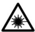
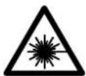
Do not stare into beam.
Class 2 laser product
OBJ BUCH-2450-006.book Page 11 Monday, December 18, 2017 12:17 PM


Deutsch | 11
Technische Daten
OBJ BUCH-2450-006.book Page 13 Monday, December 18, 2017 12:17 PM


Deutsch | 13
OBJ BUCH-2450-006.book Page 14 Monday, December 18, 2017 12:17 PM


14Deutsch
OBJ BUCH-2450-006.book Page 15 Monday, December 18, 2017 12:17 PM


Deutsch | 15
OBJ BUCH-2450-006.book Page 17 Monday, December 18, 2017 12:17 PM


Deutsch|17
OBJ BUCH-2450-006.book Page 18 Monday, December 18, 2017 12:17 PM


18 | Deutsch
OBJ BUCH-2450-006.book Page 20 Monday, December 18, 2017 12:17 PM


20 | Deutsch
OBJ BUCH-2450-006.book Page 21 Monday, December 18, 2017 12:17 PM


Deutsch|21
OBJ BUCH-2450-006.book Page 22 Monday, December 18, 2017 12:17 PM


22 | Deutsch
OBJ BUCH-2450-006.book Page 23 Monday, December 18, 2017 12:17 PM


Deutsch|23
OBJ BUCH-2450-006.book Page 25 Monday, December 18, 2017 12:17 PM


Deutsch|25
OBJ BUCH-2450-006.book Page 26 Monday, December 18, 2017 12:17 PM


26 | Deutsch
OBJ BUCH-2450-006.book Page 28 Monday, December 18, 2017 12:17 PM


28 | English
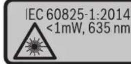
The measuring tool is provided with a warning label (marked with number 12 in the representation of the measuring tool on the graphics page).
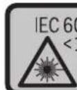
IEC 60825-1:2014 <1mW,635 nm
Laser Radiation Do not stare into beam Class 2 laser product
If the text of the warning label is not in your national language, stick the provided warning label in your national language over it before operating for the first time.

Do not direct the laser beam at persons or animals and do not stare into the direct or reflected laser beam yourself, not even from a distance. You could blind somebody, cause accidents or damage your eyes.
If laser radiation strikes your eye, you must deliberately close your eyes and immediately turn your head away from the beam.
Do not make any modifications to the laser equipment.
- Do not use the laser viewing glasses as safety goggles. The laser viewing glasses are used for improved visualisation of the laser beam, but they do not protect against laser radiation.
- Do not use the laser viewing glasses as sun glasses or in traffic. The laser viewing glasses do not afford complete UV protection and reduce colour perception.
Have the measuring tool repaired only through qualified specialists using original spare parts. This ensures that the safety of the measuring tool is maintained.
Do not allow children to use the laser measuring tool without supervision. They could unintentionally blind other persons or themselves.
Do not operate the measuring tool in explosive environments, such as in the presence of flammable liquids, gases or dusts. Sparks can be created in the measuring tool which may ignite the dust or fumes.
1609 92A 48U| (18.12.17) Bosch Power Tools


OBJ BUCH-2450-006.book Page 29 Monday, December 18, 2017 12:17 PM


English | 29
- Caution! When using the measuring tool with Bluetooth®, interference with other devices and systems, airplanes and medical devices (e.g., cardiac pacemakers, hearing aids) may occur. Also, the possibility of humans and animals in direct vicinity being harmed cannot be completely excluded. Do not use the measuring tool with Bluetooth® in the vicinity of medical devices, petrol stations, chemical plants, areas where there is danger of explosion, and areas subject to blasting. Do not use the measuring tool with Bluetooth® in airplanes. Avoid operation in direct vicinity of the body over longer periods.
The Bluetooth® word mark and logos are registered trademarks owned by Bluetooth SIG, Inc. and any use of such marks by Robert Bosch Power Tools GmbH is under licence.
Product Description and Specifications
Please unfold the fold-out page with the representation of the measuring tool and leave it unfolded while reading the operating instructions.
Intended Use
The measuring tool is intended for measuring distances, lengths, heights, clearances and inclines, and for calculating areas and volumes. The measuring results can be transferred to other devices via Bluetooth.
Technical Data
| Digital Laser Measure GLM 50 C | |
| Article number | 3601K72C.. |
| Measuring range (typical) | 0.05-50 m A) |
| Measuring range (typical under unfavourable conditions) | 20 m B) |
| Measuring accuracy (typical) ±1.5mm | A) |
| Measuring accuracy (typical under unfavourable conditions) | ±3.0mm B) |
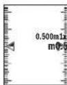
| Lowest indication unit 0.5 mm | |
| Indirect Distance Measurement and Vial | |
| Measuring range 0°-360°(4x90°) | |
Bosch Power Tools 1609 92A 48U| (18.12.17)


OBJ BUCH-2450-006.book Page 30 Monday, Decemcr 18, 2017 12:17 PM


30 | English
| Digital Laser Measure | GLM 50 C |
| Gradient measurement | |
| Measuring range 0°-360°(4x90°) | |
| Measuring accuracy (typical) | ±0.2(C)/D |
| Lowest indication unit 0.1° | |
| General | |
| Operating temperature -10 °C...+45 °C | E) |
| Storage temperature -20 °C...+70 °C | |
| Relative air humidity, max. | 90 % |
| Laser class | 2 |
| Laser type | 635 nm, <1 mW |
| Laser beam diameter (at 25 °C) approx. | |
| - at 10 m distance | 9 mm(D) |
| - at 50 m distance | 45 mm(D) |
| Automatic switch-off after approx. | |
| - Laser | 20 s |
| - Measuring tool (without measurement) | 5 min(H) |
| Weight according to EPTA-Procedure 01:2014 | 0.10 kg |
| Dimensions | 106 x 45 x 24 mm |
| Degree of protection | IP 54 (dust and splash proof)F) |
| Batteries | 2 x 1,5 V LRO3 (AAA) |
| Rechargeable batteries | 2 x 1,2 V HRO3 (AAA) |
| Setting the unit of measure | m, ft, in |
| Data transmission | |
| Bluetooth® | Bluetooth® 4.0 (Classic and Low Energy)G) |
| Operating frequency band | 2402 - 2480 MHz |
| Max. transmission power | 2.5 mW |

160992A48U|(18.12.17)BoschPowerTools


OBJ BUCH-2450-006.book Page 31 Monday, December 18, 2017 12:17 PM


English | 31
A) For measurements from the front edge of the measuring tool, applies to high reflectivity of the target (e.g. a white-painted wall), weak backlighting and 25^ operating temperature. In addition, a deviation of ± 0.05mm / m must be taken into account.
B) For measurements from the rear measuring tool edge, applies to high reflectivity of the target (e.g. white cardboard), strong backlighting and -10^ to +45^ operating temperature. In addition, a deviation influence of ± 0.15mm / m must be taken into account.
C) After user calibration at 0^ and 90^ ; An additional grade error of ± 0.01^ /degree to 45^ (max.) has to be taken into account. The left-hand side of the measuring tool serves as the reference level for grade measurement.
D) At 25^ operating temperature
E) In the continuous measurement function, the maximum operating temperature is +40^ .
F) except battery compartment
G) For Bluetooth® low energy devices, establishing a connection may not be possible, depending on model and operating system. Bluetooth® devices must support the SPP profile.
H) Bluetooth® deactivated
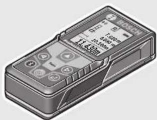
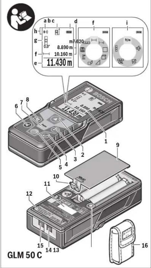
The measuring tool can be clearly identified with the serial number 11 on the type plate.
Product Features
The numbering of the product features shown refers to the illustration of the measuring tool on the graphic page.
1 Display
2 Measuring button[ ]
3 Plus button[+]
4 Button for selection of the reference level
5On/Offbutton[]
6 Bluetooth® button
7 Function button[Func]
8 Minus button[-]
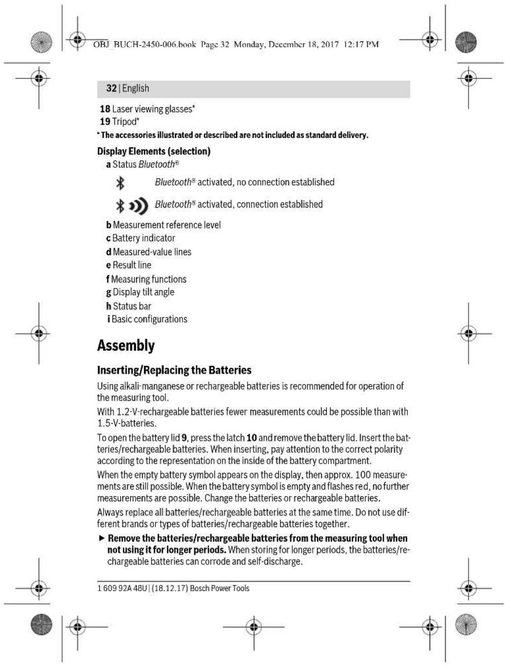
9 Battery lid
1.0 Latch of battery lid
11 Serial number
12 Laser warning label
13 1/4" Tripod socket
14 Reception lens
15 Laser beam outlet
16 Protective pouch
17 Lasertargetplate*
Bosch Power Tools 1609 92A 48U| (18.12.17)


OBJ BUCH-2450-006.book Page 33 Monday, December 18, 2017 12:17 PM


English | 33
Operation
Initial Operation
Do not leave the switched-on measuring tool unattended and switch the measuring tool off after use. Other persons could be blinded by the laser beam.
Protect the measuring tool against moisture and direct sun light.
Do not subject the measuring tool to extreme temperatures or variations in temperature. As an example, do not leave it in vehicles for a long time. In case of large variations in temperature, allow the measuring tool to adjust to the ambient temperature before putting it into operation. In case of extreme temperatures or variations in temperature, the accuracy of the measuring tool can be impaired.
- Avoid heavy impact to or falling down of the measuring tool. After severe exterior effects to the measuring tool, it is recommended to carry out an accuracy check (see "Accuracy Check of the Distance Measurement", page 42) each time before continuing to work.
Switching On and Off
- To switch on the measuring tool and the laser, briefly press the measuring button 2 [▲]
- To switch on the measuring tool without the laser, briefly press the On/Off button 5 [0]
- Do not point the laser beam at persons or animals and do not look into the laser beam yourself, not even from a large distance.
To switch off the measuring tool, press and hold the On/Off button 5 [ ].
The measured values and device settings in the memory are retained when you switch the tool off.
Measuring Procedure
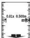
Once switched on, the measuring tool is in the length measurement function. For a different measuring function, press the button 7 [Func]. Select the desired measuring function with the buttons 3 [+] or the button 8 [-] (see "Measuring Functions", page 34). Activate the measuring function with button 7 [Func] or with the measuring button 2 [▲].
After switching on, the rear edge of the measuring tool is preset as the reference level for the measurement. To change the reference level, see "Selecting the Reference Level", page 34.
Place the measuring tool against the desired starting point of the measurement (e.g. a wall).
Bosch Power Tools 1609 92A 48U| (18.12.17)


OBJ BUCH-2450-006.book Page 37 Monday, Decembr 18, 2017 12:17 PM


English | 37
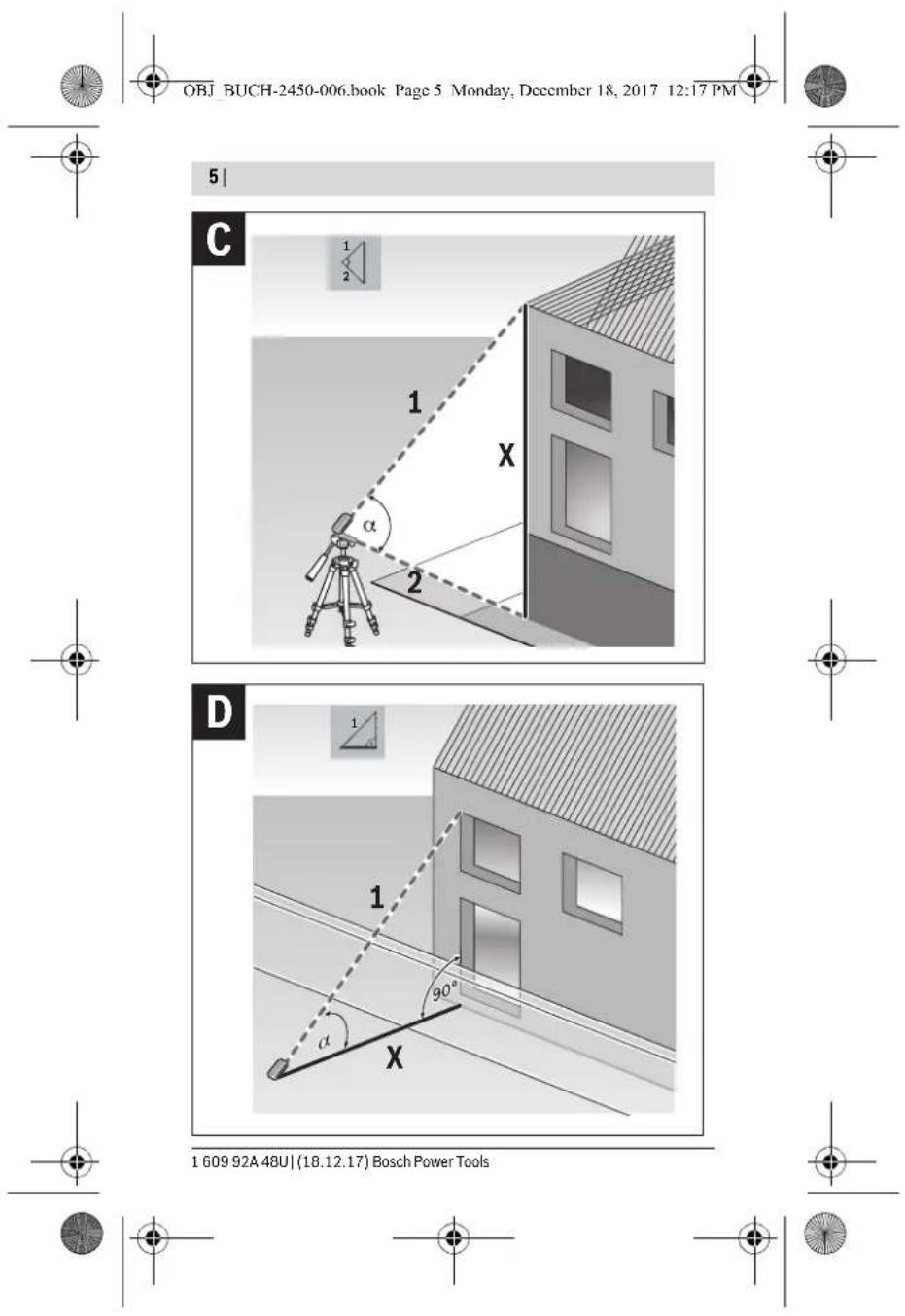
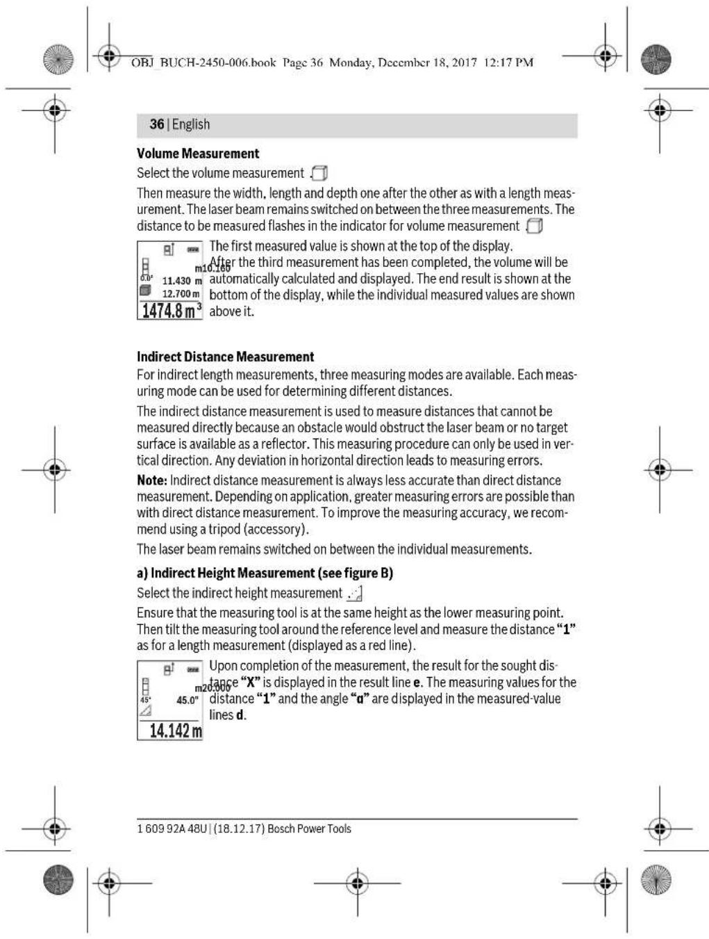
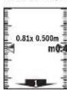
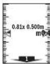
b) Double indirect Height Measurement (see figure C)
The measuring tool can indirectly measure all distances, which lie in the vertical level of the measuring tool.
Select the double indirect height measurement
Measure distances "1" and "2" in this sequence as for a length measurement.
Upon completion of the measurement, the result for the sought dis
tange X^ is displayed in the result line e. The measuring values for the
m1250
m1650
45.0° ue lines d.
8.765 m Pay attention that the reference plane of the measurement (e.g. the rear edge of the measuring tool) remains exactly at the same location for all individual measurements within a measuring sequence.
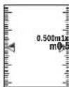
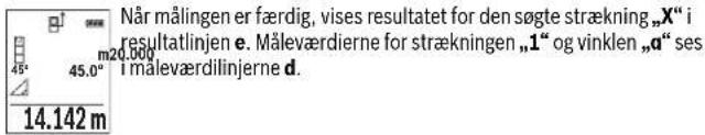
c) Indirect Length Measurement (see figure D)
Select the indirect length measurement
Pay attention that the measuring tool is positioned at the same height as the sought measuring point. Now, tilt the measuring tool around the reference plane and measure distance "1" as for a length measurement.
Upon completion of the measurement, the result for the sought dis
ance X^ is displayed in the result line e. The measuring values for the distance 1^ and the angle a^ are displayed in the measured-value lines d.
10.000m
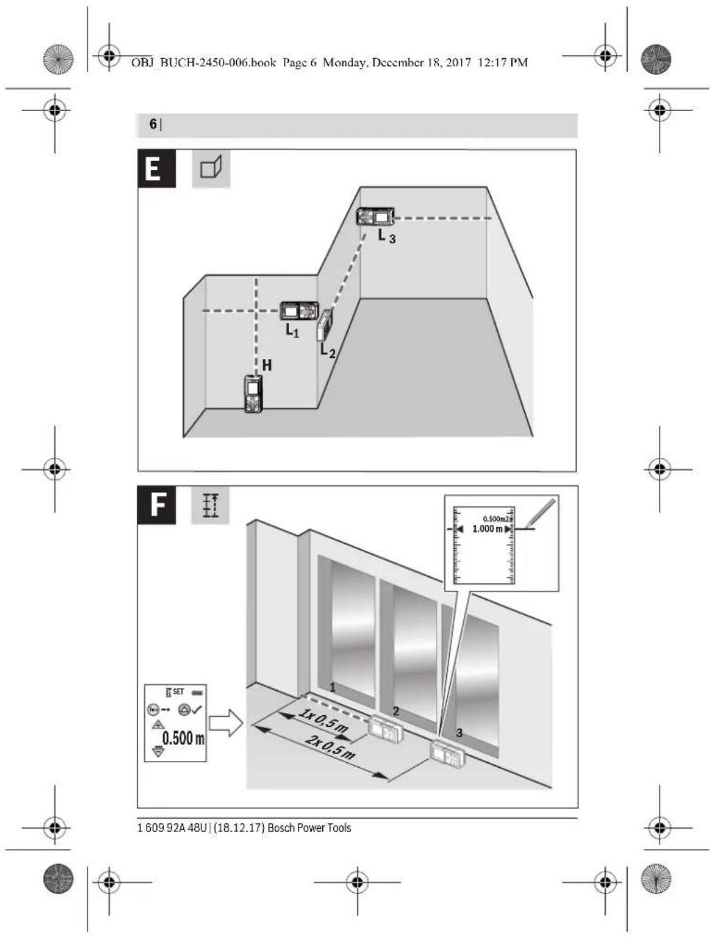
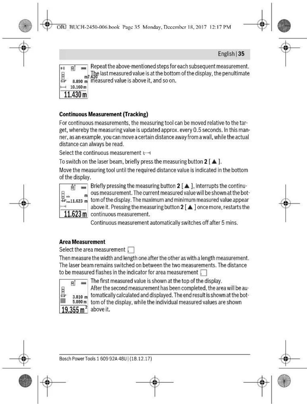
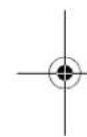
Wall Surface Measurement (see figure E)
The wall surface measurement is used to determine the sum of several individual surfaces with a common height.
In the illustrated example, the total area of several walls should be determined, which have the same ceiling height H, but different lengths L.
Select the wall surface measurement
Measure the ceiling height H as with a length measurement. The measured value is displayed in the top measured-value line. The laser remains switched on.
Then measure the length L_1 of the first wall. The surface is automatically calculated and displayed in the result line e. The last length measured value is in the bottom measured-value line d. The laser remains switched on.
Bosch Power Tools 1609 92A 48U| (18.12.17)


OBJ BUCH-2450-006.book Page 38 Monday, December 18, 2017 12:17 PM


38 | English
Now measure the length L_2 of the second wall. The individual measured value displayed in the measured-value line d is added to the length L_1 . The sum of the two lengths (displayed in the middle measured-value line d) is multiplied by the saved height H. The total surface value is displayed in the result line e.
You can measure any number of lengths L_x which will be automatically added and multiplied by the height H.
The requirement for a correct area calculation is that the first measured length (for example the ceiling height H ) is identical for all sub-areas.
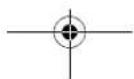
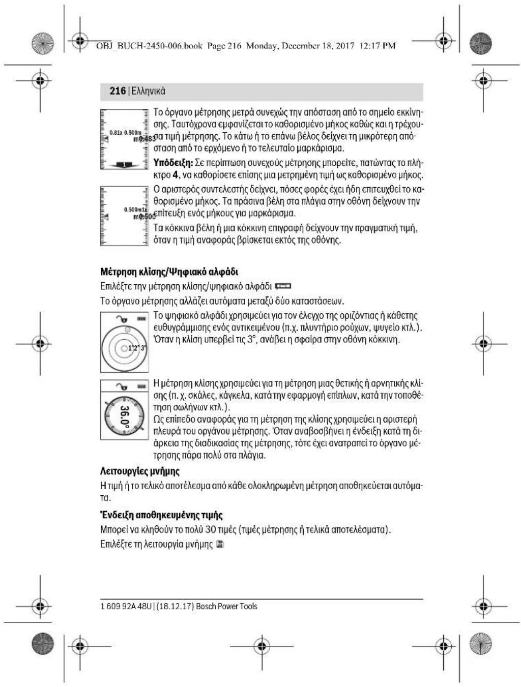
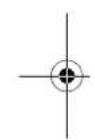
Stake out Function (see figure F)
The stake out function repeatedly measures a defined length (distance). These lengths can be transferred to a surface, for example to enable material to be cut into pieces of equal lengths or to install stud walls in a drywall construction. The minimum adjustable length is 0.1m , the maximum adjustable length is 50m .
Note: The distance from the marking is shown in the display in the marking function. The reference is not the edge of the measuring tool.
Select the stake out function
Set the desired length. Using button 7 [Func] select the corresponding digit/position and change the value with button 3 [+ or button 8 [-] .
Begin the stake out function by pressing the measuring button 2 [▲] and slowly move away from the starting point.
The measuring tool continuously measures the distance to the starting point. The defined length and the current measured value are thereby displayed. The lower or upper arrow displays the shortest distance to the next or last marking.
Note: The continuous measuring enables you to set a measured value as a defined length by pressing the button 4.
The left factor specifies how many times the defined length has already been reached. The green arrows on either side of the display indicate the reaching of a length for marking purposes.
Red arrows or red text indicate the actual value when the reference is outside of the display.
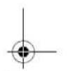
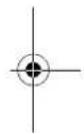
Gradient Measurement/Digital Spirit Level
Select the inclination measurement/digital spirit level
The measuring tool automatically switches between two states.
160992448U(18.12.17) Bosch Power Tools


OBJ BUCH-2450-006.book Page 39 Monday, December 18, 2017 12:17 PM


English | 39

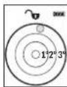
The digital spirit level is used to check the horizontal or vertical alignment of an object (e.g. washing machine, refrigerator, etc.).
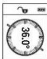
When the inclination 3^ exceeds, the ball in the display lights red.
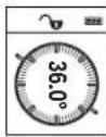
Gradient measurement is used to measure a slope or incline (e.g. of stairs, railings, when fitting furniture, laying pipes, etc.).
The left-hand side of the measuring tool serves as the reference level for grade measurement. If the display flashes during measurement, the measuring tool has been tipped too heavily to the side.
Memory Functions
The value or end result of each completed measurement is automatically saved.
Memory Value Display
Maximum 30 values (measured values or end results) can be retrieved.
Select the memory function
The number of the memory value is shown at the top of the display, the corresponding memory value is shown at the bottom and the corresponding measuring function is shown on the left.
1.890 m Press button 3 [+] to browse forwards through the saved values.
6 m³ Press button 8 [-] to browse backwards through the saved values.
If there is no value available in the memory, "0.000" is shown at the bottom of the display and "0" at the top.
The oldest value is located in position 1 in the memory, while the newest value is in position 30 (when 30 memory values are available). When a further value is saved, the oldest value in the memory is always deleted.
Deleting the Memory
To delete the content of the memory, press button 7 [Func] and select the memory function. Then briefly press the On/Off button 5 [e] to delete the displayed value.
Simultaneously pressing the button 4 and the On/Off button 5 [ ] deletes all values stored in the memory.
Adding/Subtracting Values
Measured values or end results can be added or subtracted.
Bosch Power Tools 1609 92A 48U| (18.12.17)


The number of the memory value is shown at the top of the display, the corresponding memory value is shown at the bottom and the corresponding measuring function is shown on the left.
1.890 m Press button 3 [+] to browse forwards through the saved values.
6 m³ Press button 8 [-] to browse backwards through the saved values.
If there is no value available in the memory, "0.000" is shown at the bottom of the display and "0" at the top.
The oldest value is located in position 1 in the memory, while the newest value is in position 30 (when 30 memory values are available). When a further value is saved, the oldest value in the memory is always deleted.
Deleting the Memory
To delete the content of the memory, press button 7 [Func] and select the memory function. Then briefly press the On/Off button 5 [e] to delete the displayed value.
Simultaneously pressing the button 4 and the On/Off button 5 [ ] deletes all values stored in the memory.

Adding/Subtracting Values
Measured values or end results can be added or subtracted.
Bosch Power Tools 1609 92A 48U| (18.12.17)


OBJ BUCH-2450-006.book Page 41 Monday, December 18, 2017 12:17 PM


English | 41
For more information, visit the Bosch product page, see QR code, page 8.
For data transmission via Bluetooth®, time delays between mobile terminal/device and measuring tool may occur. This can be possible due to the distance between both devices or the object being measured.
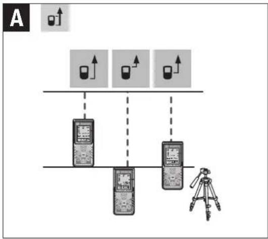
Activating the Bluetooth® Interface for Data Transmission to a Mobile Terminal/Device
To activate the Bluetooth® interface, press the Bluetooth® button 6 on the measuring tool. To activate the Bluetooth® signal, press the Bluetooth® button 6 or the button 3 [+] once again. Ensure that the Bluetooth® interface is activated on your mobile terminal/device.
To expand the functionality of the mobile terminal/device and to simplify the data processing, special Bosch applications (apps) are available. These can be downloaded in the respective stores, depending on the terminal/device.
The connection between mobile terminal/device and measuring tool is established after the Bosch application has started. If multiple active measuring tools are found, select the appropriate measuring tool using the serial number.
The connection status as well as the active connection (a) are displayed in the status bar (h) of the measuring tool.
Deactivating the Bluetooth® Interface
To deactivate the Bluetooth connection, press the Bluetooth button 6. To deactivate the Bluetooth signal, press the Bluetooth button 6 once again or the button 8 [-] or switch off the measuring tool.
Working Advice
For more information, visit the Bosch product page, see QR code, page 8.
The measuring tool is equipped with a radio interface. Local operating restrictions, e.g. in airplanes or hospitals, are to be observed.
General Information
The reception lens 14 and the laser beam outlet 15 must not be covered when taking a measurement.
The measuring tool must not be moved while taking a measurement. Therefore, place the measuring tool, as far as this is possible, against or on a firm stop or supporting surface.
Influence Effects on the Measuring Range
The measuring range depends on the lighting conditions and the reflective properties of the target surface. For better visibility of the laser beam in extraneous light, use the
Bosch Power Tools 1609 92A 48U| (18.12.17)


OBJ BUCH-2450-006.book Page 43 Monday, December 18, 2017 12:17 PM


English | 43
Working with the Tripod (Accessory)
The use of a tripod is particularly necessary for larger distances. Position the measuring tool with the 1/4" thread 13 onto the quick-change plate of the tripod 19 or a commercially available camera tripod. Tighten the measuring tool with the locking screw of the quick-change plate.
Set the corresponding reference level for measurement with a tripod by pushing button 4 (the reference level is the thread).
Error Message
If a measurement cannot be performed correctly, the error message "Error" appears in the display. Switch the measuring tool off and back on, and start the measurement again.

The measuring tool monitors correct functioning in every measurement. If a defect is detected, the display will indicate only the symbol shown opposite and the measuring tool switches itself off. In this case, have the measuring tool checked by an after-sales service agent for Bosch power tools.
Maintenance and Service
Maintenance and Cleaning
Keep the measuring tool clean at all times.
Do not immerse the measuring tool in water or other fluids.
Wipe off debris using a moist and soft cloth. Do not use any cleaning agents or solvents.
Maintain the reception lens 14 in particular, with the same care as required for eye glasses or the lens of a camera.
In case of repairs, send in the measuring tool packed in its protective pouch 16.
After-sales Service and Application Service
Our after-sales service responds to your questions concerning maintenance and repair of your product as well as spare parts. Exploded views and information on spare parts can also be found under:
www.bosch-pt.com
Bosch's application service team will gladly answer questions concerning our products and their accessories.
In all correspondence and spare parts orders, please always include the 10-digit article number given on the nameplate of the product.
Bosch Power Tools 1609 92A 48U| (18.12.17)


OBJ BUCH-2450-006.book Page 45 Monday, December 18, 2017 12:17 PM


English | 45
Republic of South Africa
Customer service
Hotline: (011) 6519600
Gauteng - BSC Service Centre
35 Roper Street, New Centre
Johannesburg
Tel.: (011) 4939375
Fax: (011) 4930126
E-Mail: bsctools@icon.co.za
KZN - BSC Service Centre
Unit E, Almar Centre
143 Crompton Street
Pinetown
Tel.: (031) 7012120
Fax: (031) 7012446
E-Mail: bsc.dur@za.bosch.com
Western Cape - BSC Service Centre
Democracy Way, Prosperity Park
Milnerton
Tel.: (021) 5512577
Fax: (021) 5513223
E-Mail: bsc@zsd.co.za
Bosch Headquarters
Midrand, Gauteng
Tel.: (011) 6519600
Fax: (011) 6519880
E-Mail: rbsa-hq.pts@za.bosch.com
Disposal
Measuring tools, accessories and packaging should be sorted for environmental-friendly recycling.

Do not dispose of measuring tools and batteries/rechargeable batteries into household waste!


OBJ BUCH-2450-006.book Page 46 Monday, December 18, 2017 12:17 PM


46 | Français
Only for EC countries:
According to the European Guideline 2012/19/EU, measuring tools that are no longer usable, and according to the European Guideline 2006/66/EC, defective or used battery packs/batteries, must be collected separately and disposed of in an environmentally correct manner.
Battery packs/batteries no longer suitable for use can be directly returned at:
Great Britain
Robert Bosch Ltd. (B.S.C.)
P.O.Box 98
Broadwater Park
North Orbital Road
Denham
Uxbridge
UB95HJ
At www.bosch-pt.co.uk you can order spare parts or arrange the collection of a product in need of servicing or repair.
Tel. Service: (0344) 7360109
E-Mail: boschservicecentre@bosch.com
Subject to change without notice.

Français
OBJ BUCH-2450-006.book Page 47 Monday, December 18, 2017 12:17 PM


Francais | 47
Laser Radiation Do not stare into beam Class 2 laser product
OBJ BUCH-2450-006.book Page 48 Monday, December 18, 2017 12:17 PM


48 | Français
OBJ BUCH-2450-006.book Page 49 Monday, Decemcr 18, 2017 12:17 PM


Francais | 49
OBJ BUCH-2450-006.book Page 50 Monday, December 18, 2017 12:17 PM


50 | Français
OBJ BUCH-2450-006.book Page 51 Monday, December 18, 2017 12:17 PM


Francais | 51
OBJ BUCH-2450-006.book Page 52 Monday, December 18, 2017 12:17 PM


52 | Français
OBJ BUCH-2450-006.book Page 53 Monday, December 18, 2017 12:17 PM


Francais | 53
Processus de mesure
OBJ BUCH-2450-006.book Page 55 Monday, December 18, 2017 12:17 PM


Francais|55
11.623 m
OBJ BUCH-2450-006.book Page 56 Monday, December 18, 2017 12:17 PM


56 | Français
OBJ BUCH-2450-006.book Page 57 Monday, December 18, 2017 12:17 PM


Francais 57
OBJ BUCH-2450-006.book Page 58 Monday, December 18, 2017 12:17 PM


58 | Français
OBJ BUCH-2450-006.book Page 59 Monday, December 18, 2017 12:17 PM


Francais|59

OBJ BUCH-2450-006.book Page 60 Monday, December 18, 2017 12:17 PM


60 | Français
OBJ BUCH-2450-006.book Page 61 Monday, December 18, 2017 12:17 PM


Francais|61
OBJ BUCH-2450-006.book Page 63 Monday, December 18, 2017 12:17 PM


Francais|63
OBJ BUCH-2450-006.book Page 64 Monday, December 18, 2017 12:17 PM


64]Français
France
Robert Bosch (France) S.A.S.
OBJ BUCH-2450-006.book Page 65 Monday, December 18, 2017 12:17 PM


Espanol 65
OBJ BUCH-2450-006.book Page 66 Monday, December 18, 2017 12:17 PM


66|Espanol
Laser Radiation Do not stare into beam Class 2 laser product
OBJ BUCH-2450-006.book Page 67 Monday, December 18, 2017 12:17 PM


Espanol 67
OBJ BUCH-2450-006.book Page 68 Monday, Decemcr 18, 2017 12:17 PM


68|Espanol
OBJ BUCH-2450-006.book Page 69 Monday, December 18, 2017 12:17 PM


Espanol 69
OBJ BUCH-2450-006.book Page 71 Monday, December 18, 2017 12:17 PM


Espanol|71
OBJ BUCH-2450-006.book Page 72 Monday, December 18, 2017 12:17 PM


72 | Espanol
OBJ BUCH-2450-006.book Page 73 Monday, Dcccmber 18, 2017 12:17 PM


Espanol 73
OBJ BUCH-2450-006.book Page 75 Monday, December 18, 2017 12:17 PM


Espanol 75
a) Medicion indirecta de alta (ver figura B)
OBJ BUCH-2450-006.book Page 76 Monday, December 18, 2017 12:17 PM


76 | Espanol
OBJ BUCH-2450-006.book Page 79 Monday, December 18, 2017 12:17 PM


Espanol 79
Restar valores
OBJ BUCH-2450-006.book Page 80 Monday, December 18, 2017 12:17 PM


80|Espanol
OBJ BUCH-2450-006.book Page 81 Monday, December 18, 2017 12:17 PM


Espanol|81
OBJ BUCH-2450-006.book Page 82 Monday, December 18, 2017 12:17 PM


82 | Espanol
Do not stare into beam
Class 2 laser product
OBJ BUCH-2450-006.book Page 87 Monday, December 18, 2017 12:17 PM


Portugues|87
OBJ BUCH-2450-006.book Page 88 Monday, Decemcr 18, 2017 12:17 PM


88 | Português
OBJ BUCH-2450-006.book Page 89 Monday, December 18, 2017 12:17 PM


Portugues|89
OBJ BUCH-2450-006.book Page 91 Monday, December 18, 2017 12:17 PM

Portugues | 91
OBJ BUCH-2450-006.book Page 92 Monday, December 18, 2017 12:17 PM


92 | Português
OBJ BUCH-2450-006.book Page 95 Monday, December 18, 2017 12:17 PM


Portugues 95
a) Medico de alterua indireta (ver a figura B)
OBJ BUCH-2450-006.book Page 96 Monday, December 18, 2017 12:17 PM


96 | Portugues
Medicão da superficie da parede (veja figura E)
OBJ BUCH-2450-006.book Page 97 Monday, December 18, 2017 12:17 PM
Portugues 97
OBJ BUCH-2450-006.book Page 98 Monday, Dccmber 18, 2017 12:17 PM


98 | Português
OBJ BUCH-2450-006.book Page 99 Monday, December 18, 2017 12:17 PM


Portugues 99
OBJ BUCH-2450-006.book Page 100 Monday, December 18, 2017 12:17 PM


100 | Portugués
OBJ BUCH-2450-006.book Page 101 Monday, December 18, 2017 12:17 PM


Portugues|101
OBJ BUCH-2450-006.book Page 104 Monday, December 18, 2017 12:17 PM


104|Italiano
Italiano
Norme di sicurezza

Class 2 laser product
OBJ BUCH-2450-006.book Page 105 Monday, December 18, 2017 12:17 PM


Italiano | 105
OBJ BUCH-2450-006.book Page 111 Monday, December 18, 2017 12:17 PM


Italiano | 111
OBJ BUCH-2450-006.book Page 115 Monday, Dccmber 18, 2017 12:17 PM


Italiano | 115
OBJ BUCH-2450-006.book Page 119 Monday, December 18, 2017 12:17 PM


Italiano | 119
OBJ BUCH-2450-006.book Page 120 Monday, December 18, 2017 12:17 PM


120|Italiano
Do not stare into beam
Class 2 laser product
OBJ BUCH-2450-006.book Page 124 Monday, December 18, 2017 12:17 PM


124 | Netherlands
OBJ BUCH-2450-006.book Page 126 Monday, December 18, 2017 12:17 PM


126 | Nederlands
| Digitale laser-afstandsmeter GLM 50 C | |
| Accucellen | 2 x 1,2 V HR03 (AAA) |
| Instelling maateenheid | m, ft, in |
| Gegevensoverdracht | |
| Bluetooth®Bluetooth® 4.0 | (Classic en Low Energy) (a) |
| Frequentieband 2402 - 2480 MHz | |
| Max. zendvermögen | 2,5 mW |
OBJ BUCH-2450-006.book Page 130 Monday, Dcccmber 18, 2017 12:17 PM


130|Nederlandsl
Menu „Basisinstallingen"
Kies de lengthemeting
OBJ BUCH-2450-006.book Page 132 Monday, December 18, 2017 12:17 PM


132|Nederlandsls
OBJ BUCH-2450-006.book Page 134 Monday, December 18, 2017 12:17 PM


134 Nederlands
OBJ BUCH-2450-006.book Page 136 Monday, December 18, 2017 12:17 PM


136|Nederlandds
OBJ BUCH-2450-006.book Page 137 Monday, December 18, 2017 12:17 PM


Nederlands | 137
OBJ BUCH-2450-006.book Page 138 Monday, December 18, 2017 12:17 PM


138|Nederland
OBJ BUCH-2450-006.book Page 141 Monday, December 18, 2017 12:17 PM


Dansk|141
OBJ BUCH-2450-006.book Page 143 Monday, December 18, 2017 12:17 PM


OBJ BUCH-2450-006.book Page 145 Monday, December 18, 2017 12:17 PM


Dansk|145
Montering
OBJ BUCH-2450-006.book Page 146 Monday, December 18, 2017 12:17 PM


146|Dansk
Ret社会各界 are working to make a difference in the way that people live and work. The new technology will allow us to be more active, more active, and more active.
OBJ BUCH-2450-006.book Page 147 Monday, Dccmber 18, 2017 12:17 PM


Dansk|147
Displaybelysning
Displaybelysningen er aktiveret permanent. Hvis der/DDRE trykkes pa nogen knapper, daempes displaybelysningen after ca. 20 sekunder for at skane batterierne/akkuerne.
Mälefunktioner
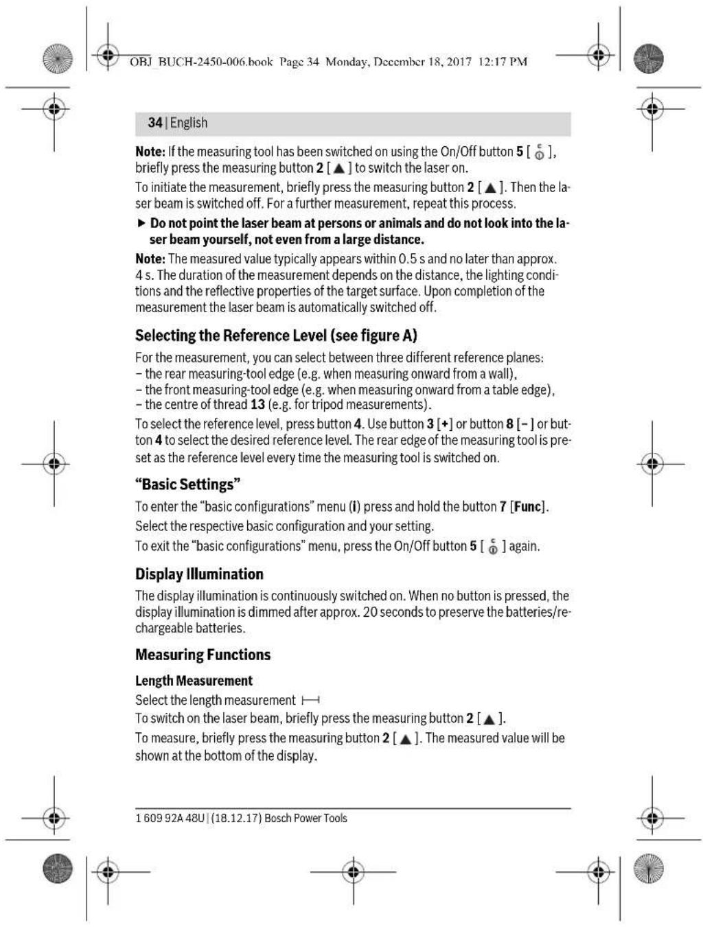
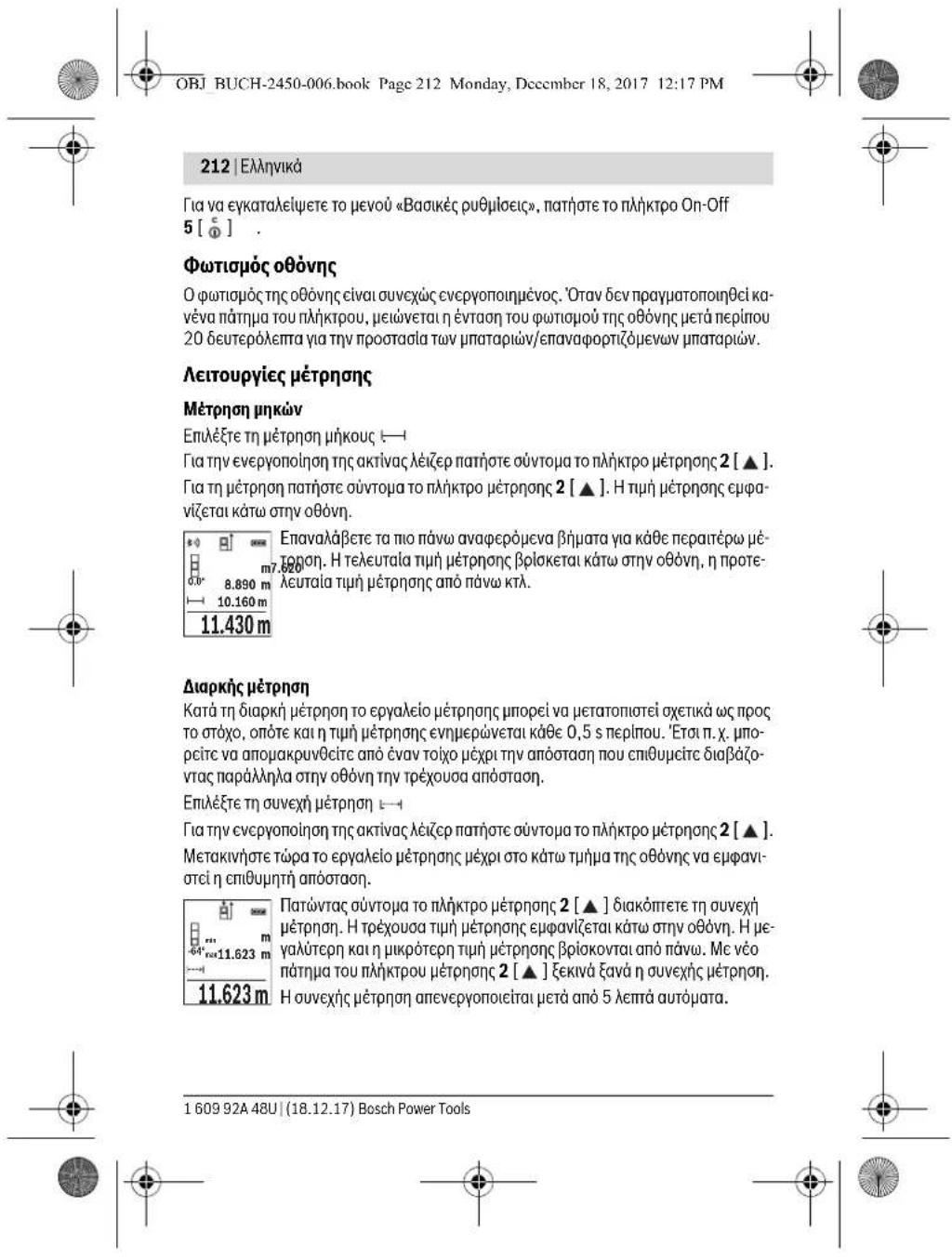
Laengdemåling
Vaelglaengdemaling
For at taende lasersträén trykker du kort pa maletasten 2 [▲].
For at malé trykker du kort pa maletasten 2 [▲]. Mälevaerdien vises nederst pa displayet.
Gentag de ovennaevnte trin for hver ny maling. Den sidste malveerdi nederst padisplayet, den naestsidste ovenover osv.
6.0 8.890m
10.160m
44.102m
11.430m
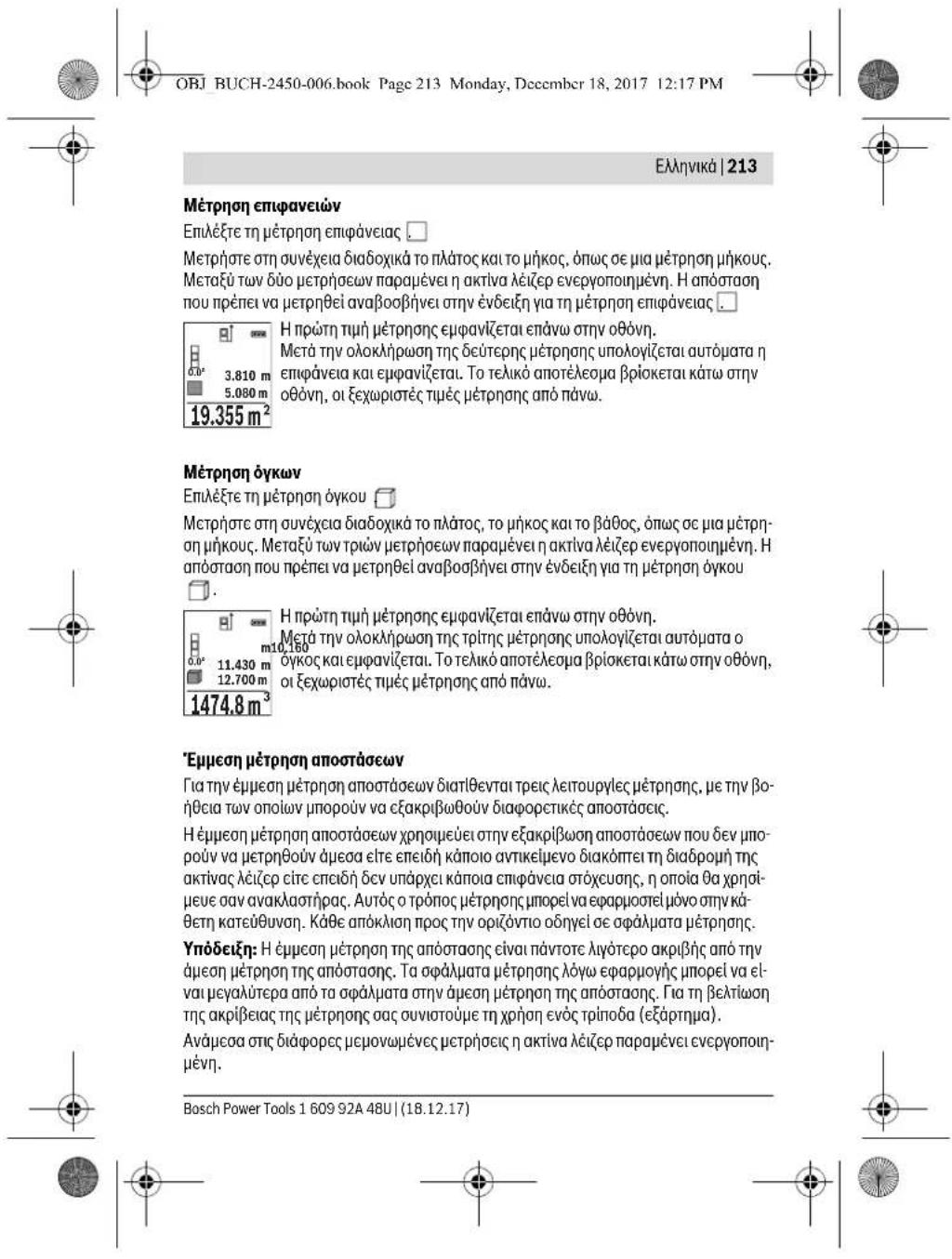
Konstant måling
OBJ BUCH-2450-006.book Page 149 Monday, December 18, 2017 12:17 PM


Dansk|149
b) Dobbelt indirekte hjojdemåling (se Fig. C)
OBJ BUCH-2450-006.book Page 150 Monday, Dccmber 18, 2017 12:17 PM


150 | Dansk
OBJ BUCH-2450-006.book Page 152 Monday, December 18, 2017 12:17 PM


152 | Dansk
Vardier adderes/subtraheres
Mälevaerdier og slutresultater kan adderes og subtraheres.
Vardier adderes
Tryk pa tasten 3 [+] ellter tasten 8 [-] for at skifte malenhed.
OBJ BUCH-2450-006.book Page 153 Monday, December 18, 2017 12:17 PM


Dansk|153
Deaktivering at Bluetooth®-interface
OBJ BUCH-2450-006.book Page 154 Monday, December 18, 2017 12:17 PM


154 Dansk
OBJ BUCH-2450-006.book Page 155 Monday, December 18, 2017 12:17 PM


Dansk|155
OBJ BUCH-2450-006.book Page 157 Monday, December 18, 2017 12:17 PM

Svenska | 157
Laser Radiation Do not stare into beam Class 2 laser product
Klistra medfoljande dekal i ditt eget sprak over varningskylten om den avviker fran spraket i ditt land.

OBJ BUCH-2450-006.book Page 159 Monday, December 18, 2017 12:17 PM


Svenska | 159
Digital laseravstandsmatre GLM 50 C
OBJ BUCH-2450-006.book Page 162 Monday, December 18, 2017 12:17 PM


162 | Svenska
OBJ BUCH-2450-006.book Page 164 Monday, December 18, 2017 12:17 PM


164 | Svenska
OBJ BUCH-2450-006.book Page 170 Monday, December 18, 2017 12:17 PM


170 | Svenska
-
rereflekt erandeytor (t. ex. polerad metall, glas),
-
porosaytor (t.ex.isoleringsmaterial),
-
ytor med struktur (t.ex. grovputs, natursten).
Anvand eventuelt for dessaytor lasermaltavlan 17 (tillbehor).
Felaktig matning ar mojlig pa snett inriktade maltyor.
Dessutom kan luftskikt med olica temperatur erler indirectr reflexion paverka matvardet.
Bosch Service Center
Telegrafvej 3
2750 Ballerup
Danmark
Tel.: (08) 7501820 (inom Sverige)
Fax: (011) 187691
Bosch Power Tools 1609 92A 48U| (18.12.17)


OBJ BUCH-2450-006.book Page 172 Monday, Decembr 18, 2017 12:17 PM


172 Norsk
Avfallshantering
Do not stare into beam
Class 2 laser product

160992448U(18.12.17) Bosch Power Tools


OBJ BUCH-2450-006.book Page 173 Monday, Decembr 18, 2017 12:17 PM


Norsk|173
OBJ BUCH-2450-006.book Page 174 Monday, December 18, 2017 12:17 PM


174 | Norsk
Formalsmessig bruk
OBJ BUCH-2450-006.book Page 175 Monday, December 18, 2017 12:17 PM


| Digital laser-avstandsmäller GLM 50 C | |
| Beskyttesestype | IP 54 (beskyttet mot stáv og vannsprut)F) |
| Batterier 2 x 1, 5 V L R O 3 (AAA) | |
| Battericeller | 2 x 1,2 V HR03 (AAA) |
| Innstilling av måleenhet | m, ft, in |
| Dataoverfæring | |
| Bluetooth® Bluetooth® 4.0 | (Classic og Low Energy)G) |
| Driftsfrekvensbänd 2402 - 2480 MHz | |
| Maks. sendeeffekt | 2,5 mW |
A) Ved maling fra forkanten pa maleverktoyet, gelder for sterk reflekerende mal (f.eks. en hvitmalt vegg),svakt bakgrunnslys og driftstemperatur 25^ .Det ma tillegg paregnes et avik pa
± 0.05 ~mm / m
B) Ved måling fra bakkanten av mäleverkåyt, gjelder for måm med hæy refleksjon (f. eks. hvit papp), sterk bakgrunnsbelysning og - 10 °C til + 45 °C driftstempoatur. Det må tillegg pärengnes en innyfylte pa ± 0,15 mm/m.
C) Etter brukerkalibrering ved 0^ og 90^ ma det tas hensyn til en ekstra stigningsfel pa
±0,01°/grader til 45°(maks.). Som referanseplan for helningsmalingen brukes den venstre siden pa måleverktoyet.
D) Ved drifttemperature at 25^
E) I funksjonen for kontinuierlig måling er den maksimale driftstemperaturen + 40 °C.
F) Unntatt batterirom
G) I forbindelse med Bluetooth® Low Energy-enheter kan det, avhengig av modell og operativsystem, hende at det ikke er muligå apprettie forbindelse. Bluetooth® enheter på stotte SPP-profilen
H) Bluetooth® deaktiviert
Serienummerer 11 pataypeskiltet er til en entydig identifisering av maleverktoyet.
Illustrerte komponenter
Nummereringen av de illustrrente komponentene gjelder for bildet av mäleverktøyet på illustrrasjonssiden.
OBJ BUCH-2450-006.book Page 177 Monday, December 18, 2017 12:17 PM


Norsk|177
Med 1,2 V-batteri kan antall mulige malinger vareindre enn med 1,5 V-batterier.
OBJ BUCH-2450-006.book Page 178 Monday, December 18, 2017 12:17 PM


178|Norsk
Måling
Etter at mäleverktjot er slätt pa, er det stiltn inn pa lenghtdemåling. For andre mälefunksjoner trykker du pa knappen 7 [Func]. Velg önsket mälefunksjon med knappen 3 [+] eller knappen 8 [-] (se «Mälefunksjoner», side 179). Aktiver mälefunksjonen med knappen 7 [Func] eller med mäleknappen 2 [▲].
OBJ BUCH-2450-006.book Page 181 Monday, December 18, 2017 12:17 PM


Norsk|181
Velg dobbelt indirekte hoydemaling
OBJ BUCH-2450-006.book Page 183 Monday, December 18, 2017 12:17 PM


Norsk|183

OBJ BUCH-2450-006.book Page 185 Monday, December 18, 2017 12:17 PM


Norsk|185
OBJ BUCH-2450-006.book Page 186 Monday, December 18, 2017 12:17 PM


186 Norsk
- strukturerte overflater (f.eks. puss, naturstein).
Bruk eventuelt laser-maltavlen 17 (tilbeher) på disse overflatene.
Feilmälinger er dessuten mulig på mälflater det siktes på skrå mot.
OBJ BUCH-2450-006.book Page 187 Monday, December 18, 2017 12:17 PM


Laser Radiation Do not stare into beam Class 2 laser product
OBJ BUCH-2450-006.book Page 190 Monday, December 18, 2017 12:17 PM


190 | Suomi
Tekniset tiedot
OBJ BUCH-2450-006.book Page 191 Monday, December 18, 2017 12:17 PM


Digitalin laseretaisyymsmittalaite GLM 50C
OBJ BUCH-2450-006.book Page 193 Monday, December 18, 2017 12:17 PM


Suomi | 193
OBJ BUCH-2450-006.book Page 194 Monday, December 18, 2017 12:17 PM


194 Suomi
Mittaustoimenpide
OBJ BUCH-2450-006.book Page 199 Monday, December 18, 2017 12:17 PM


Suomi | 199
OBJ BUCH-2450-006.book Page 201 Monday, December 18, 2017 12:17 PM


Suomi|201
OBJ BUCH-2450-006.book Page 202 Monday, December 18, 2017 12:17 PM


202 | Suomi
OBJ BUCH-2450-006.book Page 205 Monday, December 18, 2017 12:17 PM


EAAnvka 205
To nekpok epaiaio npabivetai me ia npoetonnntk maki (otny anekovion to nekpokob eyaieou otnealbae ta ypaikapapeei tov xa paktipak oip102).
0825-1:2014 mW, 635 nm
Laser Radiation Do not stare into beam Class 2 laser product
Oav to kelveo nnc npoeiionnntiknc mivaklaac dev elvaon yawoo ta xwpaac aoc, toe, npv npwn thc en o leiotouyia, kaiotre enaww toyn au ToKdAANTmivaklaa onyawoo ta nxc wpcac aoc nou nepiexetai onu oukeuaia.
Mny kateuovte nkyakiva lecp enawo oe npowna hwa kauny koiae o ioia kateuelav ony dpeon h avakweyn akiva lezep. Eto unpci va tupwocte atouja, va npokaloect atuxjura na Bauyete ta maac.
2e nepintwnnou naktiva lezepneotaa paiaacnpeneva kaeioetra patia ouveiota kai va anopakovete tokepaiaac aoeoancnTny akltva.
Mny npoBeirce ae kapiia aalayn ot niatai nieep.
Mx npaonnoaeta Ta yuaia napatponnc aeicep av npoateurtka yuaia. Ta yuaia napatponnc aeiccp xnpauocuvy ia tvk autepn avaywipion nactivac iecp xupic, owc, va npoatecuov ano tnv akivoBoia alecp.
Mxpanoioe Ta yuaia napatponc ieep ou yuaia nalou nov obi kukloopopia. Ta yuaia npataponc ieep dev npoateouv enapkwc an toyn unepwnaktnoBria (UV) kalewovn vaywipiontw xpwiatw.
Na divete to epyaleio meponc yua emakeun onoobnote o kataaannknaideevno ppoowmko ka mvo je yvntaavtaakka. Maurov tov npto EaaopaliCerai n diatnpan nnc aopaooc leitoupyiac tou epyaleiou meponc.
Mny aipivere naia va xnpaonoiouv aventnptra to epyaekio pctponc. Mnopoicxupic va to cokouv,va tuaowouu daa npoona.
Na uny epyaceotee to epyaleio metponc oepiBaaov oto onoio unapcei kduovoc eknpncn, n otono bplkovrat eupkepta uypa, aepua nokvec. 2to caotepiktooueayaleiomuontpevi va dnnioupyei ativnnpiaocki etarva avaplexbouv n akovn hi avaunpaideic.
Bosch Power Tools 1609 92A 48U| (18.12.17)


OBJ BUCH-2450-006.book Page 206 Monday, Decembr 18, 2017 12:17 PM


206|EAAyVikd
Ppooox!Kata m xpon Tou opyavou metpnoncpe Bluetoothmnpoei va npouaaetie ma aalawov oukeowkai eykataotaewv, aeponlavov kaiatpuikw oukeuw (n.x, Bmuatoobtnc kapdiac, akouotka).EnIanc dev npoei va anoklete evtalewmu qnaue ovavpoounoc kzwa oto apoo nepBaalov.Mx npaumoioe to npavyo metpnncpeBluetooth Kovtae atuipekc oukeucs, ctaouoace avepodiaouo, xnukeec ykataotaeic, emkiivduveyciaekn nepioxckai o ne pioxexavatvaewmv. Mn npaumoioeite to npyavo metpnncpe Bluetho7e aeapolada.Anopoebyete M Aetroupyia evaevayutepeovko biadotma nolu kovt sto wua oc.
To lekto ojba Bluetooth onoc enlonta eikovoyapma (ayotuna) elva kataxwpnpeva emopka ojma kai ioktnoia nC Bluetooth SIG, Inc. OnoiabnoTe xphon autow twy lekto kw onatw/ekovoyapmuatw ano ng Robert Bosch Power Tools GmbH npayatonoieitr ae n oxetik abeda xphnc.
Pepiypapn Tou npoiovtoc kal nct loxoc tou
Iapakaiaoue Eebimawote to dinlo eXwpuuoo ie nty aeneikovian tou epyaaleou me ton ank kaphote to ecbimawcvo kata tn diapkeia tnc avaywwong twv obnyiw xeiipaiou.
Xpion oupwa va Tov npoopio
To opyavo pctponnpoopicraia nptpon anootaoewv, ukwv, uawv, biaotnatawv, kioewv kai vto npolnoeipavewkai oykwv.
Ta anoreleagata nC metpnonc npopoov va petoobouv eoow Bluetooth° oAocouokuec.
Texvka xapaktnioku
OBJ BUCH-2450-006.book Page 208 Monday, December 18, 2017 12:17 PM


208|EAAyVikd
A) Kati τη μετρογασι Ακηντημιναυτόν τη μετρογας με. uŋηλ φαντοῦτη ανακλασις του στόχου (πχ. ενας λεύκες ἀμερίανεύς τόχος) Μειδει ασθένις φαντοῦ του καί 25 °C Ερρορούλα Ελεύρουγας. Eπελεύνην πρεπείνα μαυλεόγκε καίνει με μαι σωλλίας ὅμο ± 0,05 mm/ m.
B) Kato mEpiapn an ny niva axjun to opayouo pteponan, koyei va uuihikavonia oovkaanoc tou xou (n. x. evu leukoxapvtov, duvatac oovkovovovovot kai- 0^ ec+45 Cepkopaia Acouyipcaev, Ennuacov npceva unooayokicaveicmu cmpnoan 015 mm/
C) Metr taJauovon ano Toy xpyam oK a90 ngne na Angdeunup e npodero opda klanic anep 0,01/paioe ac65 (pEy).Oc emine doa apovapac yia nptpnnnc klanic xpanu peei ni apiote naepu on poyavou jpeptnpn.
D) Σε περπιωη 25°C θερμακραολίς ηετούργλίς
E) Σmλeioypaia Daopnnc meptnon npeyn theepoopaia aieioupiaacavexetai 40°C.
F) EKTO TNCnOKnCnTn mntapias
G) Ee nepiwnauu kueuvu Bluetooth® Low-Energy avokyoa to voivkko ka to hentoukyo ooutma u npocvi ma vni cuiu duvat kajia anokatoraonovbconc. OoioukceuCbluethnpcnv unonot pKouV noopla SPP.
H) Bluetooth® amevepyonuévo
O apoic oocipac 11 orny ivakda tou kataokcuaoi npaue ci yia n aoi avaywapion tou dikou aec epaiekoi uetponc.
OBJ BUCH-2450-006.book Page 210 Monday, December 18, 2017 12:17 PM


210|EAAynvka
Na aaaaetoe cic nunatapie tautoxpova. O unatapie npenei va elva oec ano tv IIO kataaekuaonkai va exouvntivia xwnptikotnla.
NaByaTe Tc mntapieacno To epyaleio petponoc otav Dev npoketai va to Xpouonohae Te apkeTo Kaip. Se neplwno paKpOxpvnc anoKeuvoc, o mntapie cmupei va okoupiaouv kai va autockpoptotovu.
Aetroupyia
Oeog aeIetroupyla
Mny apnve to evpyonoumevo epyaleio petanc aventnpno to aaaa va to 0Te Tn xpon Tou cKtoc Aitoupyiac. Mnpie va Tupawoov dAatao anaTnv activa ceep.
PpOoTeEeToepyaleio pEpnoc ano uypoaia K ano aoeon nlaikn akTivo-Boia.
Na nyn eKetete to epyaieio pTePnOnc oakpaic eepokpaoiec kai/ no ixupe c diakujavoeic eepokpaoiaoc. Tna npadeiyma, va nny to apnvte yia noan npa otro autokivno. Zne pinnwoeic ixupovsiakupavoewvntc depokpaoiaoc npie va nepiive vta oTaeponoinei npota n eoepukoiiaou epayaleiou pTePOnC npiv to xonapaimoiaactc. H akilieiaou pcyaleio pTePnOnc mnpci va aAloiwei uno akpcic eepokpaoiec /kai ixupce diakujavoeic nC eepokpaoiaoc.
Na anopoeuyere Tc loxupce npokpouaeic kai tnc wocie tou epaaleiou pertn. Meta nao xuoye xayuec, egeotepikec eniopaoe opo eaolei pertonnc thipenei, npi ouvexiaerte nTv epyola aac, va dieyete eeyxo tn akpilaeac (Bleene EEAeyoc akpbetaiae kai ntc pertonnc aoataoan), calefa 220).
OeogaeAeIoupyiaKekocAeIoupyiac
TnVevpyoynonTou opyavou pnpnncKan Tou Aep natnoe ouvtopa 0nntkpo npoc2 [A]
TnV epeyoinon tou opyavou pntancxupic lecp natnoe ouvtoua o nKto On-Off 5 [
Mny kateouvete nvi akiva aeepenawo ne npooana na 0a ka mny koiace to o liooc/n iog ngnivgaleep, gokouni gn oyean agotag.
TnV anevepyonolnou opyavou metponc kpatnoe to nKtpo On-Off 5 [ ] natnevo.
Kata nvepepyoioiou tou opyavou ptnoq biatnpovtaoi tuec kal oipuioic TnOaKeunocou Bpikovtai onm
160992448U(18.12.17) Bosch Power Tools

OBJ BUCH-2450-006.book Page 211 Monday, December 18, 2017 12:17 PM


EAnnvk211
Auaibikiaoa metpononc
Meta tv evpyoioan to opyavo metpnonc Bpioketal ont aeitoupyia mc metpnanc tou kouoc, Tia ma aAAn Aeitoupyia metpnonc natnoe to nAktpo 7 [Func]. EmAteTnv emuunn taeitoupyia metpnonc me to nAktpo 3 [+] n to nAktpo 8 [-] (Bene Aei Toupyie metpnonc, oAie6la 212). Evpeoyonnoe tne aeitoupyia metpnonc me to nAktpo 7 [Func] n e to nAktpo metpnonc 2 [ ]
MeTn 0e aeitoupyia aev enineo avapopac yia n tepon enaeyetai autopa n onioia akun tou epyaieoiu npoc. Ta n v alayn tou emneou avapopac bene EImayn eniteoavapopac, oAia 211.
Tonoetno to opyavo metponc oto emuunr oaneio ekkvnnc nnc metponc (n.x. tolxoc).
Ynobel:Edv to apyavo meptonnc evpyonohnke me to nktpo On-Off 5 [c]nntoc ouvtota to nktpto pctponc 2 [▲], yia va evpyonoiqcto loiccp.
TnEvpyonolnon Tnc metponanc natote ouvtoua tonktopepton2 [A].Me taenepeyonoieir nakiva Aiccp. Tua nepairepw metpon enavaaabeetautn tiaiaokaia.
Mny kateuovte nTv akTla valeep enawv oe npoowma na Ka mnu KoiTe e o iioC/ n ibia otnv aktiva alep, akoun kn anpeyann anoTaon.
YnobcI: H tnnm eptponnc emapavclctai ouvthwc vctoc 0,5 deutepoalettw kai to apotepo mte npinou 4 deutepoentna. H diapkeia ntc ptnpnan eapatai ao nTnv anoTaon, tic uovhkek cwniauoi kal icidntnc avakaaon nnc enipaveiaac tou otxou. Mto npac nnc metpnnc ancvcpnoicirai autopata naktiva aecep.
Emloy ennebou avapopac (Bene eikova A)
Tia n pertponn npopeire va enuEte metaEu tpoov enneBov avapopac:
-tnc nawakun tou epyalelou metponnc (n.x.yia to akoumuqa oetolxouc),
TnC npooivnC akui nou epyaleoiu (x.y. ia pertpon ano ia akui npaneiou),
- TnC PEOncTou OmeipuatoC 13 (x.yia tic pTePnoeicpe Tpinoda).
IaTny enioyou tou eninébou avapopac nathote to naiktpo 4. Me to naiktpo 3 [串 ] to naiktpo 8 [-] no naikpto 4 cieEte to eunuunto eninebo avapopac. Meta ano kabe evpyonoinan tou opyavou mertponc n niow aukn tou opyavou mertponc elvat npoppuoueovn ecinebo avapopac.
Mevou(Baoukερμioε)
Tva vepaoeTe oTo evoB Baoikc puOlaeiC (i), kpatnoTe to nAHTpo 7 [Func] no- TnuEvo.
EmleTe Tm exaotote baikn puOmuon kT mpuOmuon aac.
Bosch Power Tools 1609 92A 48U| (18.12.17)


OBJ BUCH-2450-006.book Page 214 Monday, December 18, 2017 12:17 PM


214|EAAyVikd
a) Emuon perton uwv (Baeceiova B)
EmaleTe nV emuon mepron Tou uouc
PiooEe, va elva to opyavo oto Iiou uoc, me To katw onmuo eptponc. Felpete eeta To opyavo pertonc oTo enline do avapopac kai pertnoe, onwc ae ia pertponn nKouc Tnv anotoan 以 1 (Onv oov npouoia cetai wc kokkv npaum).
MetatovepaiaoTNCeptponc to anoteloeqaiaaytnyavaanouevn 45.0° maaonXEuapavicetaiOnypaumAnotelaeopawv e.Ontuec,etpn onCyaTnAnOtaon1KaTynVviaAeaepavicovatoiCypaupeci Tmuovpertponc d.
14.142m
b) DuaH emuon pertpon uupov (Bale Ekovo C)
To apyavo metpnanc npoel va metpnoei oic anoataeic empeoa, oiolec bplakovt a 0kctoc mine do tou opyavou metpnnc.
EmaleTe n 6mAn emuon mepton tou ouoc
Meptne npwta nV anootaan 1Kai aKaIoouWc TnV anoTaon 2Oncn Heptn on unkov.
MetatovepaiaoTcetponoTo anotaleoguaVtynavaaoupeevn 45.0° m12.208 m16.213 vya nnoataon(1),tny anoataon(2)kai tyviaeepavio Vtai otypauec tuvwetponcd
8.765mΦoovtEe, kata n biapkeia tnc biabukaolac metpnoan to eninbo avo apopac nct metpnonc (n.x.niawakun Tou epayaleiou metpnonc) va npapeveoiicmuovwveecetphoeicnavrtoekipwcotny ibia then
c) Emuon mepon nukov (Blenc ekova D)
EmaEETmyepeon metponn kouc
Φoovlto, to epyaleio meptnoan va bpioketar oto Ido uoc me to avaontouevo on meio mepnong. Kllvete tupa to epyaleio meptnoan nepi to enite do avapopac kai pote nvy anotraon 1wncn otm nponunkov.
MetatovepaiaoTNCePnncTo anotelaeagya yia nvyavacntoupeyn anooataonXEuapvicietaiOnypaumH anotelecopatw e. Otniec, eptnp oncyia nvy anoataon 1Kai Tny vayia aEmuavicovtai otic ypauec tiuovpentancd.
10.000m
160992448U(18.12.17) Bosch Power Tools


OBJ BUCH-2450-006.book Page 215 Monday, Decembr 18, 2017 12:17 PM


EANVik215
Metponen emupaveov toixov (Baeene eikova E)
Hepn enipaveewtoovxnpaonoeira yto oxnpatopouo tou aobpoiatoc, noA wepovwewvewnepaveewpe to idio uoc.
TTO anekovicipevo npadetyua npenteva unaooyoiet n ouvoikn enpavcia nepiooo Tepaw toxuw, o onoi iexouv to lou uoc H, aaaa diaopopetka ukn L.
EnleTe nIeponen enpaveow toxov MetnoTo uoc H,Onw ceia eipnnon mKouc. Hun nponnc epavicetai onv enaw ypaun nponnc. Toieepnapaiveve evpyoanuevo.
MetpoTe mTaTo hKocL Tou npotou Toxou.H eHApdvia unoloyicetai autoata KcapiVicatn ypaun anoteAeaqauotc e. H TeLeutalia nip metpnonc mKouc Bpoketai otny kawypaun meptnoncd.To Aepaovce cvpvonouncvo.
3.336 m² MetpnoTe TpaTo uHkoC L2Tou deutepu Toxu.HepaivocevnOn npaaumetpnongdExwpiotTuHmptponngnpoOeTaOtoHkoC L1
To afoaia Tuu dio uikov (eupavicetai an tnaeaia yapui n peponcn d) noaaanata ctai te aoonkepuvo uoc H. H tniouoakic enipaviciac eupavicictai onyau pum anorealeopatoc.e
Mnpoeitre va pertnoeote oaaonote nepaetepw mkn Lx, ta onoi npootbevtai autopa-ta kai nannanaoiaovtai me to uoc H.
Piounoean yia oovot unoloyoiou tro enupaveiac eivai, on to npto metnpnevo uikoc (yia napadeiyua to uyoc H) npenei va eivai to iio yia oAec tic enmuepouc enipavic.
Aetroupyia opioeTeiOnc (Bene eKova F)
H letoupyia opioeotnc metpa enavaaauabavoeva eva kaobopoevo nkooc (anotao)auta unkn mnpovu vmaetaepoovnawoe ia enpuveia,yia va kataotel duvatni.x.n kon tcv oukou ae loou nukou cte maia xia yia tvkataokeur nlaoiowtolxw otv npd oon. To puiuccevo cdxto npkoc avexctota 0,1m,topeioto nkooc avexctai ota 50 m.
Yn6eIg:Stn aeoupyia opio8etnonc epaivietai otyn oovn anoataan to npapkapiqa. H avapop6ev cial n akui tou opyavou ptnong.
EmEETn aeIoupyia opioetno nC PuOte Tc emounto npkoc. EmEETe yi auto me to naKtpo 7 [Func] to avriotox npfo/0eon kai aalele Te Tn mue To naKtpo 3 [+ nTo naKtpo 8[-].
EekivnoTe Tn aeToupyia opioetnnc, nawvtaTo nAiktpo metponc 2 [ ], kai anoakpuvege apy a and to anelo ekkvino.
Bosch Power Tools 1609 92A 48U| (18.12.17)


OBJ BUCH-2450-006.book Page 217 Monday, Dcccmber 18, 2017 12:17 PM


EMnviKa1217
Enavw otnv 00vyn eipavicietao apitboc ncaanothkeuvevc tnc,kaTn avriatoxnn aoonkueyevn tui kai apiaterpa a vriatoxyn leioupyla pIePONC.
Piataote to naikpto3 [+], yia va EepuaAioete npoc ta emuoc meoa otic anoNkcevec tiEe.
Piataote to naikto8 [-], yia va EepuaAioete npoc ta niow meoa otic anoKneuvec tiEe.
Oraov mnuun neivai diaeoun kaia tui, toe katw onnv oovn eapavilctai 0.000kai enav O
H mia 1n pia kcta t on 0e 10 nyn, n vortep tui n 0n 0e 30 (oc npitwn 30 diaoouw anoekueevv uov).Kata nV aoohkeuon iaac nepaiepw Tnc oBvet a nvtote n miaia tui onyn.
Aaypaipn (23nmao) nnc mnnns
Tia n diaypaipou npieepoxevou nnc pvngn patnote to nahtpo 7 [Func] kai enaTe n aeotpyia pvngn .Meta natnote auvtopa to nahtpo On-Off 5 [ ] via va ahoene tny eupaviooevn tuhi.
TataTaoXpoVaToNAnKtpo4KaIToNAnKtpoOn-Off5 [ ]diaypaoovtaioeocotieouBploKovtaOtnywn.
OBJ BUCH-2450-006.book Page 218 Monday, December 18, 2017 12:17 PM


218|EAAyVikd
ApaipaeonTuow
TnV npaipean Tmuov nattote to nAiktpo 8[-].Hepaiepaw diaiaokaia eivai avao- yne tni diaikaaia «Ppo0ean Tuovv.
Diaypaipnmuovheptnonc
Tatovtac ouvtoa to nAkpTo On-Off 5 [ 心 ], mnoepite va oBnOe oe oBcTic aeitoupie cmuonnc TIV TEaLuta unoAooyouevntu npetponc. Tlatovtac enaveAnmuEv aoutroa to nAkpTo On-Off 5 [ 心 ], diaypavovtaoi tuipec metpnoc mc tvn avtiBem otcpa.
Alambda'povadacheptponnc
Hbaikp0buii eivun movda metponc m(m)
Evyonnajote to opyavo metpnanc.
Kparntote to nAikto 7 [Func] natnveo, yia va nepaete oTo peovu Baoke pOtei. EnleEre aft/m
Tnto to nKtpo 3 [+] no nnKtpo 8 [-], yia va aalaaet en movda aepnpone.
IaTnyeykataaleynou togeauoc mevo nathote to nAkypto On-Off 5 [c]MetaTnV anevepyonoin tou opyavou metpnong npapaevei enueyepvnpoanogkeu eyn.
Oupa bietaaphc Bluetooth
Metapopd e aae ouakeute
To opyavo metponc elvai EonAiove vo me ia movoda Bluetooth, no onola eow aoopatnc TeVXoLoyiAC emptenei T mepaoopa dboepvw oepiaueve civntec TEaikec ouokuec me dupa dienapic Bluetooth (n.x. Smartphone, Tablet).
Tlnpopopoeia yia tnc apalntne, npounoheaeic ouotmuoc ia yia uovbeon Bluetooth* mnpoei va potei otnv iotooeAia mc Bosch otn biuovun www.bosch-pt.com
PiepoaoTepec npnpopoeic mnpelre va bpelte oTn eAia npoiovtoc Bosch, Bane KwduKoc QR, eAida 8.
Kata netaopopa d6oepvovuogu Bluetooth® npope va napouoiaotuv kuaotepe 0eic pctEu Tn KIVNTc TEaikcuoc uokueucn kai Tou opyavou metponq. Mtopei va opecia-tai anooraan tw vdu ouakeuwv metaEtu tou n to ibio to avikeleveo metpnong.
Evpyonolnon TcOpuac dietaPc Bluteoth yia nIeapopa 6ebouevov ae Ia KnuTn teuku oukeun
Tnvepyooinq TcBupacdienaqCBluetooth nntote to Nktpo Bluetooth 6 Tou opyavou pcpponc. Ta nvycepyooinon Tou anpatoc Bluetooth nntote cek vou
160992448U(18.12.17) Bosch Power Tools


OBJ BUCH-2450-006.book Page 219 Monday, December 18, 2017 12:17 PM
EAMVik219
To nAnktpo Bluetooth6 n To nAnktpo 3 []. BeBaaWBeTe, oTn Oupa diicnapC. BluetoothOtnv KInnT ouKeun ac cival evpyonoiEvn.
Tn enktaan Tou eupouc Tuv leaoupyw Tn KnuTt caleKc ouakeun kai ta Tny anonolnon Tnc eneepyaolac Tuv geoewv elva biaeuec eideke ec appuoyec Bosch (Apps). Autcmupeite avaloya me Tnv teakuauakeun va tic katetbaeote otra avirotoxa kataotjura.
MToTnEvapEn Tnc eapApoync Bosch anokaiatataun ouvbcn taTu nKivntncuiknc oukeunk kau Tou opayouu pTeponc, EdvBoeounv nepioootepa evpyonoineva opyava pTeponc, enuEto KaatalAn opyavo pTeponc, me t Bonthea tou apoiouo ceipac.
H katataan ouvbcconk kawc k an evcyonounevn ouvbean (a) epaivicta on npum kataotaan (h) tou opyavou ptnan.
Anepepyooinan nC 8upac biuaqic Bluetooth
TnV anevepyonoin nC ouvdeocn Bluteothn natnoTo nAikpo Buteoth6. TnV anevepyonoiou natoC Buteothn natnoE kveou nAikpto Buteoth6 n to nAikto 8[-] nanevepyonoiote to opyavo mepponc.
YnobsieEeepyaoic
Pepoostepec nnpopopoe mnpelre va peltre otn oalba npoiovtoc Bosch, 1e Kwukoc QR, eAida 8.
To opyavo metponc eivai exonaupevo me aoupuat th cen taepnoc. Oto mikol nepiopiaol aeoupylaac, x.x.eeponlava n voookoea npenei va npovtai.
Tevkoc unofoelEe
Kata n diapkeia tnc metpnanc dev empteneta va eivai kalumuevoc oute o paokc anpnc 14 oure n eooc nackrivaac aeep 15.
To opyavo mctponc dev cinnpenetai va metakivnnci kata tn diapkeia mac metpon. I' auto tonoBentote To opyavo mctponc kat to duvatov oe ia otaepn enipaveia n empaveia epaanc.
Emipoeic otyn nepioxh metpon
H nepiox n pntanc eapatai anu uavnke cwniaou kai tic idotntec avakaaonnc TNC nipaeiaac otoxu. Ta tiv nautepn opatottna tnc akivac lece xpnoiaoieite ae nepimuan duuvatoeipokou pofoc ta yuaialecep (Eaptnma) kai tov miva ka otoxu lecep 17 (eaptnma), nanevepyonoiate tn vni epiaote otoxu.
Bosch Power Tools 1609 92A 48U| (18.12.17)


OBJ BUCH-2450-006.book Page 220 Monday, December 18, 2017 12:17 PM


220|EAAynuKd
Embpaooeo anotaleogmuetpnan
Otrope eni diaopopetikov enipaveov dev anokaleietai, diapopa quaika vaoveva vo oynooov oe apaivec metepnoic. MetaTu wv aaw npoketai yia:
Eeeyoc akipieac kai nct metponc anooraon
Mnopeire va aeYeEeTe Tny akpiBia tou opyavou metpononc wC eHc:
EnleTe mtaaepan anoataon metponanc ao nepinou 3 exc 10 m mko, nnc onolac ywupicakipoc to mko (n.x. to naotoc tou xipou, to avovya nnc npotac). H metpon npenei va vilek ano euviokec ouvthetakec, dn. anobotaon metponcnnpenei va biokctat orov cawtepiko xipo kai cnmpaveia tou atoxou metponcnpei va elai aleka kai va exei kaah avkaakan.
-MetpnoTe mV anoToaon 10 opec diaoxika.
H anokkianTwv ExwpotovmuoTneonm eon mtn emtpentetai va evpctai to noa 4 mm on ovovukn npoxnnc anootao nptponnc nee uovikocovhkec. Sniieae Tic ptnoeic, ia va unopeite oe ia apoyote npxovikn oynuvauykprivete nnakpiia.
160992448U(18.12.17) Bosch Power Tools


OBJ BUCH-2450-006.book Page 221 Monday, December 18, 2017 12:17 PM


EAMVik221
Epyaiae to tpinobo (eiuko eapntma)
H xpnn evoc tpiobou eivai atapaintn ibiaitepe ae meyalec nootaoei. TonoBenttoe to epayae peetponen e 1o4" oneipuwa 13 endvw otny naoka taexieac avtikatataonq to pio 19 n endaw oe vce tpo so an to kaiov eupio kai biidwote to kal a n Bila opeewong n cnaakac taexieac avtikatataonc.
OBJ BUCH-2450-006.book Page 223 Monday, December 18, 2017 12:17 PM


Türkce|223
Do not stare into beam
Class 2 laser product
OBJ BUCH-2450-006.book Page 224 Monday, December 18, 2017 12:17 PM


224 | Türkçe
OBJ BUCH-2450-006.book Page 225 Monday, December 18, 2017 12:17 PM


Türkce|225
OBJ BUCH-2450-006.book Page 228 Monday, December 18, 2017 12:17 PM


228|Türkce
Isletme
Calistirma
OBJ BUCH-2450-006.book Page 229 Monday, December 18, 2017 12:17 PM


Türkce|229
OBJ BUCH-2450-006.book Page 231 Monday, December 18, 2017 12:17 PM


Türkce|231
Endirekt uzaklik ölcümü
OBJ BUCH-2450-006.book Page 232 Monday, December 18, 2017 12:17 PM


232 | Türkçe
c) Endirekt uzunluk ölcümü (Bakirüz: Şekil D)
OBJ BUCH-2450-006.book Page 233 Monday, December 18, 2017 12:17 PM


Türkce 233
OBJ BUCH-2450-006.book Page 234 Monday, Dccmber 18, 2017 12:17 PM


234 | Türkçe
Bellek degeri gostergesi
OBJ BUCH-2450-006.book Page 235 Monday, December 18, 2017 12:17 PM


Türkce|235
OBJ BUCH-2450-006.book Page 236 Monday, December 18, 2017 12:17 PM


236 | Türkçe
OBJ BUCH-2450-006.book Page 243 Monday, December 18, 2017 12:17 PM


Polski|243
OBJ BUCH-2450-006.book Page 245 Monday, December 18, 2017 12:17 PM
i|245
OBJ BUCH-2450-006.book Page 247 Monday, December 18, 2017 12:17 PM


Polski|247
Montaž
OBJ BUCH-2450-006.book Page 248 Monday, December 18, 2017 12:17 PM


248 | Polski
OBJ BUCH-2450-006.book Page 250 Monday, December 18, 2017 12:17 PM


250 | Polski
Pomiar ciagty
OBJ BUCH-2450-006.book Page 253 Monday, December 18, 2017 12:17 PM


Polski|253
OBJ BUCH-2450-006.book Page 256 Monday, December 18, 2017 12:17 PM


256 | Polski
Interfejs Bluetooth®
OBJ BUCH-2450-006.book Page 257 Monday, December 18, 2017 12:17 PM


Polski|257
OBJ BUCH-2450-006.book Page 258 Monday, December 18, 2017 12:17 PM


258 | Polski
Robert Bosch Sp. z o.o.
Do not stare into beam Class 2 laser product
160992448U(18.12.17) Bosch Power Tools


OBJ BUCH-2450-006.book Page 261 Monday, December 18, 2017 12:17 PM


Cesky|261
Neni-li text varo\neho stitku ve Va\sem naro\dim jazyce, pak jei prd pr\nvnu\nedenim do provozu prelepte dodanou samolepkou ve Va\sem naro\dim ja\nzyce.

Laserovy paprsek nemite proti osobam nebo zvifatum a nediveje se do primeho ani do odrazeheno laseroveho paprsku. Muze to zpusobit oslepeniobservable, nehody nebo poškozeni zraku.
OBJ BUCH-2450-006.book Page 263 Monday, December 18, 2017 12:17 PM


OBJ BUCH-2450-006.book Page 265 Monday, December 18, 2017 12:17 PM


Cesky|265
Montáz
Nasazeni/vymena baterii
Pro provoz měřicho prístroje je doporučeno použivani alkalicko-manganovych bateri nebo akumulatoru.
OBJ BUCH-2450-006.book Page 266 Monday, December 18, 2017 12:17 PM


266 | Cesky
OBJ BUCH-2450-006.book Page 267 Monday, Dcccmber 18, 2017 12:17 PM


Cesky|267
Osvétlení displeje
Osvetleni displeje je zapnute trvale. Pokud nestiskete zdne tlacitko, osvetleni displeje se po cca 20 sekundach ztlumi kvuli setfen i bateril/akumulatoru.
Méricifunkce
Merené délyk
Zvolte merenélek
Pro zapnuti laseroveho paprsku kratae stisknete tlaitko meren 2 [ ]
OBJ BUCH-2450-006.book Page 272 Monday, December 18, 2017 12:17 PM


272 | Cesky
OBJ BUCH-2450-006.book Page 273 Monday, December 18, 2017 12:17 PM


Cesky|273
Dali informace na jodete na produktov strance Bosch, viz QR kod, strana 8.
Pri prenosu dat pres Bluetooth® muze mezi mobilim koncovym zarizenim a mericim pristrojem dochazet k casove prodleve. Muze to byt zpusobene vzdalenosti obou zarifenne nebo mefenym objektem.
Aktivace rozhrani Bluetooth® pro prenos dat na mobilni koncové zarizeni
Pro aktivaci Rozhrani Bluetooth stisknete tlacitko Bluetooth 6 meficiho prifstroje. Pro aktivaci signalu Bluetooth stisknete znovu tlacitko Bluetooth 6 nebo tlacitko
OBJ BUCH-2450-006.book Page 274 Monday, December 18, 2017 12:17 PM


274 | Cesky
Bosch Service Center PT
K Vapence 1621/16
692 01 Mikulov
Na www.bosch-pt.cz si si muzete objednat opravu Vašeho stroje nebo nahradi dily online.
OBJ BUCH-2450-006.book Page 277 Monday, December 18, 2017 12:17 PM


Slovensky | 277
Bud'te opatrny - ak pouzivate ine ako tu uvedene obsluzne a reatacné privky alebo volte ine postupy. Moze to mat'za nasledok nebezpecnu expozi ciu ziarenia.
Tento meraci pristroj sa dodáva s vystražnym stftkom (na grafickej strane je na obrázku meracieho pristroja označený cislom 12).
IEC60825-1:2014
<1mW,635nm
Laser Radiation
Do not stare into beam
Class 2 laser product
Ked'ne t y stystranehno stltka v jazyku Vasej krajiny, pred prvym pouzitim produktu ho prelepte dodanou nalepkou v jazyku Vasej krajiny.

Nesmerujte laserovy luc na osoby ani na zvierata, ani si na nepozerajte prrameho ci do odrazeneho laserveho luca. Moze
to sposobit oslepenie osb, nehody alebo poskodenie zraku.
Pokial laserovy luc dopadne do oka, treba vedome zatvorit oci a okamzite hla vu otoct od luce.
Na laserovom zariadení nevykonávajte ziadne zmeny.
Nepouzivale laserove okuliare ako ochrane okullare. Laserove okuliare sluzia na lepsie zviditelenie laseroveho luc, pred laserovym ziarenim vsknehrania.
Nepouzivaje laserove okuliare ako slnecné okuliare alebo ako ochranné okuliare v cestnej doprave. Laserove okuliare neposkytuju upn u ochranu pred ultra-fialovym ziarenim a znižuju vnimanie farieb.
Meraci pristroj nechavajte opravovat'len kvalifikovanemu personalu, ktory pouziva originale nahradne suciastky. Tym sa zaruci, ze bezpečnost meracieho pristroja zostane zachovaná.
Zabrante tomu, aby tento laserovy meraci pristroj mohl bez dozoru pouit deti. Mohli by neumyselne oslepit ine osoby.
Nepracujte s tymto meracim pristrojom v prostredi ohrzenom vybuchom, v ktorom sa nachadzaju hor'avé kvapalny, plyny alebo hor'avy pripadne vybusn'prach. V tomtro meracom pristroi sa mozu vyvtaraf iskry, ktoré by mohli uvedeny'prach alebo vypary zapaliit.
Bosch Power Tools 1609 92A 48U| (18.12.17)


OBJ BUCH-2450-006.book Page 278 Monday, Decembr 18, 2017 12:17 PM


278 | Slovensky
Pozor! Pri pouzivani meracieho pristroja s rozhranim Bluetooth® moze dojsk r uşeniu inych pristrojov a zarladeni, lietadiel a medicinskych zarladeni (napriklad kardiostimulatorov, načuvacich pristrojov). Taktiež nie je mozné uplne vylucit negativny vplyv na ludi a zvierata nachadzajuce sa v bezprostrednom okoli. Meracji pristrojs rozhranim Bluetooth® nepouživaje v blizkosti medicinskych zariadieni, cerpacih stanic, chemickh zariadieni, oblastí's nebezpečenstvom výbuchu a oblastí's pritomnosfou vybushin. Meracji pristrojs funkciou Bluetooth® nepouživaje v lietadiłach. Zabrante prévádzke pristroja dlhşi cas v priamej blizkosti svojho Tesla.
Slovné oznăcenie Bluetooth², ako aj obtrazové znaky (logá) su registrovanymi ochrannymi známkami a vlastnictvom spolocnosti Bluetooth SIG, Inc. Akékol'vek použitie toto slovného oznăcenia/obrazovych znakov firmou Robert Bosch Power Tools GmbH je licencované.
OBJ BUCH-2450-006.book Page 280 Monday, December 18, 2017 12:17 PM


280 | Slovensky
A) Pri merani od prendehr hrnay meracieho prifstroja, plati pre velmi dorre reflexne vlastnosti ciela (napriklad nabeli no natrecta stena), slabe osvetlenie v pozadla prevadzkovu teplotu 25^ .Dodatocne je potrebne poctaf's odchylkou ± 0.05mm / m
B) Pri merani od zadnej hany meracieho pristoja, plati pre vysoke reflexne vlastnosti ciela (napr. biely karton), silne osyveltien v pozada i prevadzkovu teplotu - 10^ a +45^ . Okrem toho je potrebné pečitāt sodchylkou ± 0.15mm / m .
C) Poi kalibracii pouzifatelom pri 0° a90° sa musi zohladn Navye chyba stipania ± 0,01 / stip-nov az 45° (max.). Ako zakladna rovina pre meranie sklonu sluzi /ava strana meracieho pristroja.
D) Pri prevadzkovej teploe 25°C
E) Vo funkci Trvalé meranie je maximána prevádková teplota +40°C.
F)s vynmkou priehradky na baterie
G) Pri pouziti pristrojov Bluetooth*. Low Energy môze byt podla modelu a prévázkové systému možné, ze sa neyvor spojenie. Pristroje Bluetooth* musia podporovat SPP profil. H) Bluetooth* deaktivovany
Na Jednoznacný identifikaciu Vásho meraceho pristroja slúži sériové cislo 11 na typovom stitku.
Vyobrazene componenty
Cislovanie jegnotlivhych zobrazenych componentov sa vzfahujne na vyobrazenie meraceho prostroja na grafickej strane tohto Navodu na pouzivanie.
1 Displej
2 Meraci tlaicido[]
3 TlaCIDlo Plus[+]
4 Tlaicidlo Volba vztajnej roviny
5 Tlaicidlo vypinača[ ]
6 Tlacidlo Bluetooth®
7 Tlačidlo funkcii[Func]
8 Tlacidlo Minus[-]
9 Viecko priehradky na baterie
10 Aretácia vekapriehradky na baterie
11 Sertové císló
12 Vystrażnystitok laserového pristroja
13 1/4"zavit stativu
14 Prijimacia sosovka
15 Vystup laseroveho ziarenia
16 Ochranná taška
17 Laserová cieřová tablárka
160992448U(18.12.17) Bosch Power Tools


OBJ BUCH-2450-006.book Page 281 Monday, December 18, 2017 12:17 PM


Slovensky | 281
OBJ BUCH-2450-006.book Page 282 Monday, December 18, 2017 12:17 PM


282 | Slovensky
Ked'meraci pristroj dlhsi cas nepouzivate, vyberte z neho baterie, resp. akumulatorovc clanky. Poacas dlhseio skladovania by mohl baterie alebo akumulatorovc clanky korodovat a mohl by sa samocinne vybjat.
Použivanie
Uvedenie do prevadzky
Nenechavajte zapnuty meraci pristroj bez dozoru a po pouziti meraci pristroj vzyvynite. Laserovy luc by mohol oslepit ine osoby.
Meraci pristroj chrante pred vlhkom a pred priamym slneynm ziarenim.
Meraci pristroj nevystavujte extremnym teplotam ani ziadnemu kolisaniu teplot. Nenechavajte ho odlozeny dlhsi cas napr. v motorovom vozidle. V pripevecsieho rozdielu teplot nechajte naiprv meraci pristroj pred jeho pouzittemperova'na teplotu prostredia, v ktorom ho budete pouzivat. Pri extremnych teplotach alebo v priade kolisania teplot moze byt negativne ovplyvnena preciznost meracieho pristroja.
Zabrante prudkym narazom alebo padoh meraceho pristroja. V pripe de intenzivnejseho vonkajieho zasahu na meraci pristroj by ste mali predtym, akobudetePokracovatvpraci,vzdyvykonafskuspu presnosti (pozri,Kontrola presnosti merania vdialenosti", strana 291).
Zapinanie/vypinanie
- Na zapnutie meracieho pristroja a lasera krátko stlăcte meracie tlačidlo 2 [▲].
- Na zapnutie meraceho pristroja bez lasera krato ksta sta tvepina 5 [
Nesmerujte laserovy luc na osoby ani na zvlerata, ani sa mi nepozerajte do laserovheho luce, dokonca ani zacej zdialenosti.
OBJ BUCH-2450-006.book Page 287 Monday, December 18, 2017 12:17 PM
Slovensky | 287
obidvoch dlzok (zobrazeny v strednom riadku nameranych hodnot d) sa vynasobi ulo- zenou yskou H. Celkova plocha sa zo brazi sa vi radku yysledkov e.
OBJ BUCH-2450-006.book Page 288 Monday, December 18, 2017 12:17 PM


288 | Slovensky
OBJ BUCH-2450-006.book Page 289 Monday, December 18, 2017 12:17 PM


Slovensky | 289
Spocitavanie hodnot
Nasledujuci priklad opisuje spočitavanie ploch:
OBJ BUCH-2450-006.book Page 290 Monday, December 18, 2017 12:17 PM


290 | Slovensky
Pri prenose udajov prostrednictvom Bluetooth® moze dojsk casovemu oneskoreniu medzi mobilyn koncovym zariadenim a meracin pristrojm. Moze to byt ovplyvnene vzdialenostou medzi obidvomi pristrojmi alebo smotnym meranym objektom.
OBJ BUCH-2450-006.book Page 291 Monday, December 18, 2017 12:17 PM


Slovensky | 291
OBJ BUCH-2450-006.book Page 292 Monday, December 18, 2017 12:17 PM


292 | Slovensky
Práca so stativom (Prisluşestvo)
Laser Radiation Do not stare into beam Class 2 laser product
OBJ BUCH-2450-006.book Page 295 Monday, December 18, 2017 12:17 PM

Magyar|295
OBJ BUCH-2450-006.book Page 297 Monday, December 18, 2017 12:17 PM


Magyar|297
OBJ BUCH-2450-006.book Page 298 Monday, December 18, 2017 12:17 PM


298Magyar
OBJ BUCH-2450-006.book Page 299 Monday, December 18, 2017 12:17 PM


Magyar|299
OBJ BUCH-2450-006.book Page 302 Monday, December 18, 2017 12:17 PM


302Magyar
Az elso meresi eredmny a kijelzo felso rzesen kerul kijelzrese. A masodik meres befejezese utan a keszulek automatikusan kiszamitja es kijelzi a feuletet. A vegeredmny a kijelzo also rzesen, az egyes ki-1onallo mert ertek felette lathatok. 19.355 m2
Terfogatmeres
Jeloljekia fogatmerest.
OBJ BUCH-2450-006.book Page 303 Monday, December 18, 2017 12:17 PM
Magyar|303
OBJ BUCH-2450-006.book Page 304 Monday, Dccmber 18, 2017 12:17 PM


304Magyar
OBJ BUCH-2450-006.book Page 305 Monday, December 18, 2017 12:17 PM


Magyar|305
OBJ BUCH-2450-006.book Page 306 Monday, December 18, 2017 12:17 PM


306 | Magyar
OBJ BUCH-2450-006.book Page 307 Monday, December 18, 2017 12:17 PM


Magyar|307
PekomeHnyetcOuHCTnTb HNCTpyMeT OT nbIIN NoCle KaKdo HcNoIb3oBaHH.
XpaHeHne
Heo6xOaHMo xpaHHTb B cyXOM MeCTe
HeoXOJHMO XpaHnTBaIIN OTIOCTOUYHKOB NOBbIeHHbIX TEMpepaTy IN BO3JeCTBnCOnHeuHbIX Nyuei
- npxpaheHH Heo6xoHMo H3eRaTpeKOro nepenapaTeMnepaTpy
ecnHHTpymEHT NOCTaBnaETCR B MMRKOBCMKNEPEKO MEHdyETCR XPAHNTb HHTpymEHT B 3TOI 3aUNTHOYNAKOBKE
- noipobhble Tpe6oBAHnK yCIOBnAM xpaHeHn CMOtpnte B FOCT 15150 (ycnoBne 1)
Bosch Power Tools 1609 92A 48U| (18.12.17)


OBJ BUCH-2450-006.book Page 312 Monday, Decembr 18, 2017 12:17 PM


312 | Pycckn
TpaHcnpToPbOvKa
Kateropnueckn He donyckaetra naeHne HIObIe MexaHueckne BOSdECTBna Ha ynapokBky npn TpaHCnpTIPOBKe
- npn pa3py3ke/norpy3ke He nOlynckaTcHcNoIb3oBaHne IIO6o BnDa TeXnIK, pabotaioue no npHHunny 3aKmma ynaKOBKn
IIOpObHbIe Tpe6oBaHnK yCIOBnM TpaHCIOptNPOBKn CMOTPHTe BTOCT 15150 (YcNOBHe 5)
Yka3aHHNo 6e30nacHocTH

Ia oecneeyenH 6eonachn Hndexho pa6oTb c H3mepe TebhBIM HcTpymemtO dONKb6bIt npouHTahbH c6noD TaBCB BCE HcTpykU. HcnOb0BaHN H3mepeTbnHO rHCTpyMeHa He CootBETCBN C HactoHHy Kka3AHMn YpeBaO NOBpEXHm HHTERPMOBAHBHx 3aunHTbIX MEXAHN
MOB. HkOrDa He N3MeHnTe Do Hey3HaBeMocTh npEynpeDntelbHbIe TaBnKu HA N3MePHTelbHOM NHCPTPYMEHTe. XOPOUo COXPAHnTE 3Ty NHCTPKYIO H INPEPABAUTE EE BMECTE C INPEDAUYEN H3MEPHTelbHOI NHCPTPYMEHTA.
BHHMaHHe -HCnONb3OBAHHe DpyTH He yNOMaHybIX 3Decb 3JIeMeHToB ynpabNeHH HperynHpOBaHH Nn DpyTH MeTOoB 3KcNpyTaunu MoKeT noDBeprHyb Bac onachomy dnn 3DopobBa n3nyenHIO.
H3mepTehbln HnCTpyMeHT Noctablanetc npedynpeDtenbHO Ta6nnKo (Ha cTpaHue c K306paxeHem H3mepTeBHO HnCTpyMeHTa nOKa3aHaNoH OHeMoP 12).
Laser Radiation Do not stare into beam Class 2 laser product
EcnTnePnpDnTeBHO TabnKHe Ha3bke Baeu cTpaHb,3aKleIe Iero nepE npBOeKcNpyataue He npHaeraemn HakKeHkoHa3bike Baeu cTpaHb.
He HanpaBraIte Nuy na3epa Ha nioe HnH XNBOThbIX camH He cmOTpHe Na pmoHnn OptPaxaeMbHny na3epa.3TOT nuY MOKET CnHNT BIOe, CTbT PnHHoH HeCcAChTO CNYaAR NH NOpeDHT Tna3.
160992448U(18.12.17) Bosch Power Tools


OBJ BUCH-2450-006.book Page 313 Monday, Decembr 18, 2017 12:17 PM


Pycckn | 313
B cnyuae nonadannna nasephoro nyaa B rna3 rna3a hyxho HamepeHHo 3a-KpbIb HemeDneHNO OTBePHyTbCnOTnya.
He MeHnTe HnUero B nA3epHom yctpoNCTBE.
HepnmeHrae na3epbte OKN B KaucctBe 3aunThbix OOKOB. Na3epbte OOKCNyKAT DnI Nywero pacno3HaBHHaepHO Lyu, ONaHKO OH He 3aunuaOT Na3epHOrO HnyeHn.
HepnmeHne naepehble oukB kaueeTbe connechbix oukOB HnB ynuHOM DBHXEHNIaephe bueKHe daIOT nonHO 3aunbl ot ynbtpafoenotoro Hnyehn HxuyduaHOT BocpnaTne Kpaoc.
Pemont Baewero H3mepntenbHoro HnctpyMeHa T npuyaTe TOBko KBanHnnpoBAHOMy nepcoHany, HcNob3yra Tohko opHHaBHe 3anaCbIe qACh. 3TNM o6ecneYBaTaC 6e30NaChOCTb H3MePeHTbHO H-CTpyMeHa.
He pa3pewaiTeTAMNONb3oBaTcna3epbHIMn3MePHTebHBMnHCTpyMeHOM63a30pa. OHMOrT HeyMbllneHHO cCnEINbIIOe
He pa6oTaIe Cn3MePHTeBbHIM HcTpyMeHToM Bo B3pbIOonacHOcpe, no6bH3OCTOn TOrpOuHX XNKOcTei, Ra3OB NbIN. Bn3MePHTeBbHOM HcTpyMeTE MOrYt O6pa30BaTbCnHKpbl, OT KOTOpBX MOKETBOCnIAmEHNTbCnblNnnapbl.
OctopoKHO!PnHcNoB0aHHN3MepTeBHOHRHCTpyMeHa c BluteothoB 03MOXbH NOMEXnI DpyTHx np6bOpB HycTahOBok, CaMoNEtOB H MeuHNCHHX AnnapaTOB (HApN, KApNOCTHMyrAToPO, CHyXOBxAnnapaTOB).KpmeTOR, HeNB3aONHOCTbKKnIOHTb HAeCEHe BpeHa XHOJIMCBA HENOCPECTBEHHO6Bn3OHTNIOJAM H XKNBOHM. He NOnb3yTECb H3MEpHTeBbHM HcTpyMeHToC bLuteothoB6bNH3MeHINHcKHX AnnapaTOB, 3anpABOHTbIX CTAHU, XMHueCKNX YCTAHOBOK H TePPHTOPH, Ha KOTobX CyueCTByET OnaCHOCTb B3pbBa Hm MOrY nPoBoNTbC B3pbHBbIe PabToH. He NOnb3yTECb H3MEpTeBbHM HcTpyMeHToC bLuteothoB6 Camonetax. CtapaiTeCb HE BkIOuAt er Ho Ha npdoJXHTbeHoB E HenocpeCTBeHHo6bN3OCTn OT Taea.
CnoBechbl ToproBb 3nak Bluetooth® n rpaΦnueckn 3nak (Norottn) HbIaHotc 3apeHCTPpOBaHBHbTobApbHbIM 3nakOM N cObCTBeHOCtBbO Bluetooth SIG, Inc. Kompanh Robert Bosch Power Tools GmbH nconnbetyet 3tot cnobechbl TobapbHb 3nak/ no nluen3nn.

Bosch Power Tools 1609 92A 48U| (18.12.17)


OBJ BUCH-2450-006.book Page 314 Monday, December 18, 2017 12:17 PM


314 | Pycckni
OnncHne npoDyKta n ycnyr
Ponanycta,OTKPOHTe paKNAHNO CTPAHUY C NINIOCTpaAUMN HCHPTyMeHTa 0ctabnIte ee OTKpbTOn, noka BbNHaCyAe pyKOBODcTO NO 3Knpyataun.
PpIMeHHeHn No Ha3HaueHHIO
M3mepntbHbHnHCTpyMeHT npEHa3HaeH nI H3mepeHn paCToHH, IINH, Bblcot, ydaHHeN yKNOHOB n paCeTa IIOUaedn OobemOB.
Pe3yNbTaTbI H3MepeHn MOxHNo nepeDaTb Yepe3 Bluetooth® Ha pyrne np60pbI.
TexHHueckne daHHble
OBJ BUCH-2450-006.book Page 316 Monday, December 18, 2017 12:17 PM


316 | Pycckn
A)ПиИЗМЕРЕНИОТепЕДERTКУРАИЗМЕРЕТБОННHCTPМЕТАДЛСТЕВСТЕВСТЕВСТЕВСТЕВСТЕВСТЕВСТЕВСТЕВСТЕВСТЕВСТЕВСТЕВСТЕВСТЕВСТЕВСТЕВСТЕВСТЕВСТЕВСТЕВСТЕВСТЕВСТЕВСТЕВСТЕVBONKOBIOIPOKATAEKHTNCHOCO6HOCTBO(HAPN.,BILKPAUHEHNAI BENOI KPCAKO STENA),CnAOI3aHIDNOCDCBKINHpaboeyTeMTENPaRpyb25°C.DonOHNTeBHO HNYKOHNXCOJNTB3OKTNOHEHHOPN4KaT0,05MM/M
B)ПинИЗмЕренгхОТаднeroКрЯнИЗмЕртELHOrO HINCTPyMENTa,ДeДСТВITELHNOДЯ ВICOKOуразКАпгELHONCHOCNTOUEN(HAPn.,БeNB儿KAPTOH),CINHOBФОHOBOI NOCDCBTKI Npabo-уtempepaTpybIOT-10-6Cdo+45C.DonOHHTeBLHOHyKHOHCXODuHbBnBnHHNNoPpKa±0,15MM/M.
C) Iocne KanbokpOnnbnBcAteIenm npn 0^ n90"HyHXy uYHbTbAtBoJOnoNHTHeBHyo NorpeuHIOCTbUa ± 0,01^ / rpa yc, do45" (MaKc.) BKAeCTBe NIOCKOCTN OTCeta BbCTyTaETNeBa CTPOHa HnmePHTBHO HnCTpyMeHa.
D) npa paboeey tempepatye 25^
E) B pexnme npoJOnKntenbHOrO n3MepeHnMaKc. pa6oay TempepaTycoCTaBnT + 40°C.
F)3aHCKHIOHHeHMeCekHHnDnBaiapeeK
G) Bππbopax BluTooth3 -Low Energy (HhAoe 3hePronotpeBneHne) bAaBcIMoCTH OT MOneHHn H onepaunHnn ChTeMb CoedHNHeMe MoKer He yctahabNbaTbCra. PnBbOpj BluTooth3 doNkHNb nopeKnBbrt npOΦHn SPP.
H) Bluethothe 1eakTHBPOBaH
OIOHOHNAHIAEHTNTHFNKAUHA Bawero H3MePHTENbHO H1cTpyMeHTA BO3MOKHa IIOceHHOMy HOMePy 11 Ha3aBODCKo TabnHKe.
1306paXeHHbIe coCTaBHbIe qACTH
HymepaunipneDctabnHbixcoCTABHbixyacteBbINoHHeNoH3obpaKeHHO H3-MepntbHOrO HcHTpyMeHTaHa CtpaHnce CnnIOCTpaHmN.
1Диспнeй
2 KhoNka H3MepeHnA [▲]
3 KhoIka «PiIOc[+]
4 KhoNka Bb6opa nIOCKoCTn OTCyeTa
5 BbikniouaTeB[
6 KhoNka Bluetooth
7 KhoNka peKmHa [Func]
8KHonKa《MHHC》[-]
9 Kpbuika 6aTaapeHoro OTecka
10ФнкcatopКрblшкбат apeHOrTo OTecka
11 CepHHbH HOMep
12 PepynpdntelbHa TaBnUka na3ephOro n3nyehn
13 Pe3b60Boe OTBepCthe nIaTnBa 1/4"
14PnHMMHnH3a
160992448U(18.12.17) Bosch Power Tools


OBJ BUCH-2450-006.book Page 317 Monday, Deccmber 18, 2017 12:17 PM


Pycckn | 317
15 BbIXoI na3epHoro lyua
16 3aunthbmyeXon
17 BnHpaMapka
18 Oukn Dn npabotb CnaepbHm HnctpyMeHTOM
19 117aTnB
*306paXeHHbIe HIN ONHcAHHbIe PnHADJIeXHOCTH He BXOaT B CTAHApTHbI KOMIneKT NOCTABKN.
Hdikatopby(Bb6op)
a Ctauyc Bluetooth®

Bluetooth® aKTbHbPOBaH, CBaB He yCTaHOBeHa

Bluetooth® aKTHBnPoBaH, CB83b yCTaHOBHeHa
bIIOCKOCTbOTcYeta nH3MepeHHN
C HnHkAtoP3apXKeHHocTHaKKyMnTOpH06atape
d N3mepeHHbte 3HaueHH
Pe3ynbTa
F Peknmbi H3mepeHH
gNndkaTOp ytna HaKnloHa
h Cstatcna stpoka
IOCHOBHbHe HaCTpKn
C6opka
YctahOBka/3aMeHa 6aTapeek
B IN3MpeHIN HNCTpyMeHTe peKOMEnyETcHcNoIb3OBaTb 10nOuHO-MapraH-ueBbE baTapeKN Wn akkymIaTObhe bataen.
CakkymyTOpHbIMn 6aTapeMn Ha 1,2 B Bo3MOxHO MeHbIe N3MepeHH, Yem C 6aTapeKaMaHa 1,5B.
TtO6bIOTKpbITb KpblkUy 6batapeHoro OTeCeka9,HaKMHTe fHKcatop10nCHMMTE KpblkUy 6batapeHoro OTeCeka. BCTaBte 6batapeHHnAkkymyrtOpHe batapei. CneHrnte 3a npabHbHO HONJRAHPOCTbBO COOTBeTcBnC H3o6paKeHHem HA BYTPenH cTTOPEHO KpblkUy 6batapeHoro OTeCeka
Pn npBOM nOBHEnHHpyCTO rCMBbONa 6aTapeKN HaDcNJIe MoKHO BbINOHtBE ue np6bl.100 H3mpeHnn.EcnH cMbON 6aTapeKN pcyTo N MHaTe KpaChbIM
Bosch Power Tools 1609 92A 48U| (18.12.17)


OBJ BUCH-2450-006.book Page 318 Monday, Decembr 18, 2017 12:17 PM


318 | Pycckn
JaIbHeHnHe H3MepeHHa HeBO3MOxHb.3aMeHHTe 6aTapeKn HIn aKKyMylTOpHbIe 6aTapen.
Bcerda3aemHnTe Bce 6atapeKn/AKKymyIaTOpHbIe 6atapeOnHOBpeMeHHo. NcNoJIb3yIte TOLbKO 6atapeKn/AKKymyIaTOpHbIe 6atapeOnHOrO pON3BOJNTeRnC ODNHaKOB0E MKOCTbIO.
BbHMaTe 6atapeHK/akkMyIaTOpHbIe 6atape H3 N3MePeHtBeHoro HcTpyMeHb,ecNb BblNTbeHbOe Bpem He 6yDte erocnlo3oBaT. PnH dInTeHbOM XpaHeHH BO3MOKHa Koppo3H INi CamopaprJaKa 6atapeek/AkkyMlyaToPbHbX 6atape.
Pa60Ta c HhctpymehtOM
3Kcnnyataaun
He octabnIte 6e3 npcmoTpa BkIOUeHHbN3MePHTbHbN HcTpyMeNTbBbIKouaIte erno nocne hcnolb30BaHna. pyrtne Nua Moryt 6bIb ocienneHbI na3epHbIM nyOHm
3aunuatae H3mepntbHbHn HnctpyMeHT O T BnA rH n npmbix cOnHeuBix ny-uei.
He noDBepraTe H3MePHTenbHbHnHCTpyMeHt Bo3dEChTBHO 3KCTpeMaBhix Temnepatypn HtempeatpybHex nepaNoB. BuctHOCTH, He octabTneero HAnHTe bHoe BPemr B MaunHne. Pnp60bIbHx nepaJax TempepaTy Cchaana DaIte H3MePHTenbHOMy HnCTpyMeHTy cAunmHsPoBAtc BcOTo TEMpepatpy, npexJe Yem HaunHbTa paBoTa c HmM. 3KCTpeMaHbHbe TEMpepatpyi H TempepatyBe npaNbMoYt OTPuCaTeNbHO BnHaB Ta ToOHCTb H3MePHTenbHO IHCPTpymeta.
H36eraIte CNbHbIX TOUKOB H naeHHN H3MePHTenbHOro HnCTpyMeNTa. nOcNE CnBbIX BHeuHHX BO3JeCTBn HA N3MePHTeBbHn HnCTpyMeT peKoMeHnyETc npoBeptb erToOHctb, npexKe Yem npoDoJXaTb paOtaB c HnCTpyMeTHOM (CM. «PiPoBePKa ToUHOCTH N3MepeHH PaCtOAHN», cTp. 329).
OBJ BUCH-2450-006.book Page 320 Monday, December 18, 2017 12:17 PM


320 | Pycckn
Дя Вьбopa плоскостгпОТСЕТа HabКNTе KНONКУ 4. KНONКОЗ 3 [+] ИИ.KHONKOK 8 [-], ИИ.KHONΚОВ 4 BbIb6Pte HeJIaMyEу ПлоскOSTь OTCHTeTа.ПОСЕ КAKDOTO BKIOUHeHH N3MpeHtBHOrO HHTcPymeHTA ПлоскOSTь OTCHTeTа RJIETcR3aHAR KpOMA.
MeHIO《OChOBbIe HAcTpoiKn》
YTo6bI IIOACTb MHeIO OChOBHbIE HAcTPOKIN (I), yIepKINBAITE KHOIKKY 7 [Func]. BbIbepHTe COOTBETCTByOIO OCHOBHyIO HAcTPOKHy N CBOIO HAcTPOKHy. YTo6bI BbITN3 MeIO OChOBHbIE HAcTPOKIN, HAKMITE BbIKIOUATENB5 [C]
Iopcbetka dncnne
NcBETKa DnCnner NOCTHO BkIOUeHa. Ecn He HaxmnaOToCn HnKAKne KhoNK, NOCBETKa DnCnner B Cenx 3KOHOMn6aTapeek/AKKyMnyIaTOpHbix 6aTapeep np6n. uepe32 c nprnyuaetaC.
Pexhmbln3mpehenn
N3mepeHne nnHHbI
Bb6epntpeKMMN3MepeHHaINHbI. UTo6bl BKNIOHTb Na3epHbI NyU, KOPOTKO HAKMITE Ha KHONKY N3MepeHHa 2 [▲]. UTo6bl npOn3BcTn H3MepeHHe, KOPOTKO HAKMITE Ha KHONKY N3MepeHHa 2 [▲]. N3-MepEHoe 3aueHne OTo6paKaetcB HHNKeY aCtHn DnCpIeR.
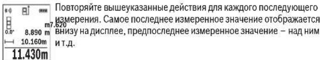
IpoJOnKHTenbHoe H3MepeHHe
Pn npOdoJNKeTbHOM 3MpeHnn H3MepeTbeHbHbHnHCTpyMeHT moKHO nepeBnRtBt OHOTcENbHOeHN, nPn STOM 3MpeHneBHe 3aHeHMe AKTyAInHNPyETcN pN6N. kakdbte 0,5 c. Bb MokeTe, Hanp., nepeBHeBaTcBc oT cTeHbHa Heo6xDnHMe pacctOHHe, AKTyAInHbHe paccToHHe BCEJa OT6paKaTaEaTcHa NdCnIeNee.
Bb6epHTepeKHM npOOnKHTenbHOro n3MepeHnI 4. UTo6bl BkNIOHTb Na3epHbI Npy, KOpOTKO HxMNTe Ha KNONky n3MepeHn2 [▲]. IpeEBnAHTe n3MePHTeHbHbHn HnCTpymEHT Do TEX NOP, NOKA BH3y HnCTpyMeHT He oTo6pa3HT kenaemoe pacCToRnHe.
160992448U(18.12.17) Bosch Power Tools


OBJ BUCH-2450-006.book Page 321 Monday, December 18, 2017 12:17 PM


Pycckn | 321
KopoTKM HAkaTHeH Ma KHONky H3MepeHHN 2 [ ] peXHM pOdoJKNH TeBbIX H3MepeHH NpepblBaetc. Tekyuee H3MepeHHoe 3aueHHe NoOpbaKaTeCH Bn3y Ha DCnCHe. MakCMaJIbHOe H MNNMauJIbHOe H3 MepeHHIe 3aueHHe OTo6paKaHOTcH aH Nm. Pn NOBTOPHOM HaxaTH Ha KHONky H3MepeHHN 2 [ ] ONaTB BkIOuaycTc pOdoJKNTeBHOe H3MepeHHe.
PexnmpoDOnKHTeBbHix H3MepeHH ABToMaTHueCKH OTKIHOaTcH epe3 5MHN.
H3mepeHne nloaann
Bb6epHTe pexHM H3mepeHn IIOuaaI □
Iocne3tOroH3MepbTeNoOuepeDnUHPHHyKak npnH3MepeHnXdNHB. Mexdy 06oHmH3MepeHnMaHnHaepbHy nuy OCTaetcBkHoueHHbIM. H3MepeEmbI oTpe3OK MHaTaET HaHnHkKaTope H3MepeHnPiOnuAdn
日 3.810 m 5.080m 19.355m² 蹲Boe H3MepeHHoe 3HaueHHe OTO6paKaTeC BBepyx HaDCnIe. Pocne 3aBepueHHn BTOPo H3MepeHHn IIOuaDb paccuHTbBaETc ABToMaTHueCKn H TO6paKaTeC. KoHehny pe3yNbTaT OTO6paKaTeC BH3Ny Ha DCnIe,OTdEhBHe I3MepeHHhe 3HaueHHe -HaHIM.
H3MepeHHe 06bema
Bb6epntepezxmH3mepeHnO6bema
Iocne3TOrnH3MepbTeNoOuepeHINHHyINHHy6HHyKAKnnH3MepEHNNHb. MeKdy TpeMa H3MepEHNMnA3epHbNnyoctaetcBKNoueHHbIM. H3MepEmbIOTpe3OKMNraeTaHaHNHKaTope H3MepEHNAOBema
1474.8m3
KocbeHHoe H3MepeHne pacCToHHN
IJI KOCBeHHORH3MepeHHa pacCTOHHN HMeETcTn peKHMa H3MepeHHa, c NOMObHO KOToPbIX MOXHO H3MeepTa p3NJHbIe OTe3KN.
KocBeHHoe H3MepeHme paccToHHn CnykHTIa H3MepeHHn paccToHHn, KOtOpblc HeBO3MOxHO H3MePbTb PpAMbIM PyTEM, NCKoJIbKy Ha TpaekTOPM Nyca CyueCTByET IIpeNATCTBHe HmHET ZeIEeBOIOBepXHOCTn, CnyKaaJeu B KaueCTBe OTpaKaTeN.
Bosch Power Tools 1609 92A 48U| (18.12.17)


OBJ BUCH-2450-006.book Page 322 Monday, December 18, 2017 12:17 PM


322 | Pycckn
3TOT CIOOCB N3MEpeHHN MOKET HCN0JIb3OBAbTcBc TOnbKO B BepTNKaIbHOM HapBaJIeHHN. IIOBOE OTKLOHeHNE BROPINHOHTaBbHOM HappaBHeHH BeTe K OwHbKM B N3MepeHHX.
Yka3aHHe: Henpmaoe n3MepeHHe pacCToHHB BcERdaTe MeHee ToHbpe3yNbTaT cHm pmeo n3MepeHHe pacCToHHB. IORpeuHOCTn 3MepeHHe MOryt 5bItb, yHtNBiBA CneuNfky npMaehHH, 60JIbWMH cEe pIINP pIaMOM n3MepeHHn pacCToHHA. JIra NOBIIeHHe TOHOCHT n3MepeHHa Mbl peKOMeHMyE HcONb3OaBt 8tATHB (npHADNEKHOCTb).
BnepepbBe MeJy OTeNbHbIMn H3MepeHnMa n3epHbI NyocTaetc BKnIOueHbIM.
a)KocBeHHoe H3MepeHHe BbICToBc (cm.phc.B)
Bb6epnte pexnKocBeHHoro H3MepeHn BBc0tbl
CneHNTe 3a TEM, YTO6bI H3MEpHTeBbHb HnCTpyMeHr HaxOHNcRa Ho OHO Bbcote C HNHEH ToKOH N3MEpHBe.3Ate HAKNOHHe T3MEpTeNbHb HnHCTpyMeHr NO OTHO He KIOIOCKoTH OTCHTe A HmEpeTbe OTeP3OK «1, KAKToDenaETcR npH3MepeHHnHb (Ha HcINCepeTcABeHBO BnDEk PAcHOHNH).
b)Дбоиhoe KocbeHnoe H3MepeHne BbcotblcM.pnc.C)
H3MepTeIbHbI HHTCPyMeT MoKET KOCBeHHO H3MEpTa IIO6bI paCCTOHHN,NEKaUne B BEPTKAbHOBINIOCKOCTH H3MEpTeJIbHO IHCTpyMeHTa.
Bb6epnte peKHM DBOHORO KOCBEHNHO N3MEpeHnBaBICtB]
H3MepbTe, KaK npn H3MepeHHN DmHbI, PaCCToHHN 111111111111111111111111111111111111111111
8.765m Cnepnte 3a TEM, uTo6bBo BpEmnH3MepeHHN nIOCKoCTb OTCyTe (Hanp.,zADHHK pRn H3MePHTenbHORO IHCTpyMEnTA) HAXOHNACb PnBCEx EDHHuHbIX H3MepeHHX Bo BpEMr Opeaunn H3MepeHHN CTporo Ha OJHOM NTOX MEcTe.
160992448U(18.12.17) Bosch Power Tools


OBJ BUCH-2450-006.book Page 324 Monday, December 18, 2017 12:17 PM


324 | Pycckn
PexHM pa3MeTKn (cm. pnc.F)
BpeXHME pa3MeTKN NOCTOHHO OTMePRAOTC ONPeDeneHHbIe DnHHbI (pacCTOHHH). 3TH NINHb MOXHO NEPEHOCHITb H NaOBepxHOCTb, HANp. dNr OTPE3AHN OAnHAKOBHXt OTE3KOB MaTePHNA HIN DnI MOHTnPOBaHHa KApKaCa IINr TnHCOKAPToHHo 6UHNK. HAcTpaHbAeMaH MmHMmaHbHa DnHHa CoCTABnReT 0,1M, MaKcHMaHbHa DnHHa COCTaBnReT 50 M.
Yka3aHHe: B pexHMe pa3MeKn OTO6paKaaeTcPacCTOHHe DO OTMeKn Ha DCnnee. OnpHOn ToUcko He ABnTcK Pau H3MePeTbHOr HCHTpymEHa.
Bb6epHTe pexkM pa3MeTkn II.
3aadaTe xenaeMyO pInHy. DnI 3TOr KOHNKO7 [Func] Bb6epHTe COOTBETCTBYIOuO uHpy/pa3pHn H3MeHHe 3HaueHHe KHOKNo3 [+] HIN KHOKNo8 [-].
BKnIOHTpeKHMpa3MeTKN,HakBaHa KHOIky H3MepeHHN2[ ],H MeJIeHHO ydaJIHITecbOT HaHaBHONTOHKN.

N3MepHTeNbHbI NHTcpMyENTnpeBbHbN 3MepReT paCtOaHHeNo HauNaHbHO TOnKHe. PtN 3OM OT6pKaAIOTeY Ka3AHbNe DmHbN To Ktey4ue N3MepHHe 3aHaeHHe. BepXHH NII HkHKnr CTpeNka Yka3bJaet Na HauMaHbHee PaCtOaHHe No cIeNduoJenn Hn npoiJno OTMeKN.
Yka3aHHe: Ecn npn HenpepbBbHOM H3MepeHHn HkAaTb KhoNky 4, MoXHO 3daTaB n3MepeHHoe 3HaueHne B KaueCTBe Yka3aHHo DnHbI.
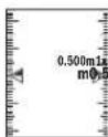
Ko3fHnneHT CNEBa yka3bIaet, cKONbKO pa3 6bIa NOCTMHrTa3aHaH HnHa.3eHehle cTpeKNi no 6okam dncnner yka3bIaIOT Ha DOCTNKeHHe HxHHO nnHbI nO TMeuaemoro OTe3Ka.
Kpacna Ctpenka nn Kpacna MapknpoBka yka3bIbaOT Ha qaktnueckoe 3haueHne, KOda 3taJIOHoe 3haueHne pacnnonoxe HBe DNcnnie.
H3mepeHne yrna haknoHa/LnΦpOBoB Batepnap
BbIbePHTe H3MepeHne yrTa hakloHa/uzdpobBo BATEpnc
H3MepHTeIbHbI HnCTpyMeHT aBtOMaTHueCKN IpeKNIouaETcMAxNy DByMa 3TmMn peKMamH.

UppoB0B Batepnap Cnyknt dnnpoBepKn rnp3ohTaIbHcTH HnI BepTKA/hoBCTN IIOJIOJEHHN OBeKTA (HaP.. CtnpaJIbHO MauHHbl, XOJIOnBIHnKA H T.J.).
Pn npBbWeHn HkIOna 3° WapNK Ha DmCnnee RopNT KpaChbIM.
160992448U(18.12.17) Bosch Power Tools


OBJ BUCH-2450-006.book Page 325 Monday, December 18, 2017 12:17 PM


Pycckn|325
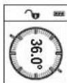
PekmH3MepeHHaKaHOHa cnyKHT dIy H3MepeHHnNoBemaHnYkNOHa (HaNP..NecTHNuHbIX npoTeOB, NecTHNuHbIX nnoaDOK, npnNoTROHKe MeBEN, pNp npoknaKe Tpy6 n. d.).
B Kaueche IIOKOCTH OTCHe Ta BbCTyNAe TReBa CTOPOA H3MEpuTeHb Horo HnCTpyMeHa. EcnB NpOucee NsMpeHn MRaet HnDKaTOp, To NmepTeJIbHHN INCHPTyMeHT CNbHO HaKIOHEB B6ok.
Функшпamathn
3HaueHHe HnpeyIbTaKaxdoRoOTeJIbHOrO hMepenHcOxpaHETCBnamTn ABToMaTHuCeKn.
OTo6paXeHne coXpaHeHHbIX 3HaueHm
DocyHbMaKcHMyM 303HaueHH (u3MepeHHbx 3HaueHH uN KOHeHbIX pe3ynbTaTOB).
BbIbepeHTeФyHKUIO naMaTIN
BBepy Ha nCnlee OTo6paKaTaC THeMepaueKn NaMaTHn, BHN3y COOT 8.7620m 8.890m HaxHmAte Ha KOnky 3 [+] npeHnCTbBAHnna CoXpAHnHex 3Ha 430.16m3 Wnepe.
HaxnmaTe Ha KhoNky 8 [-] nIpeHnctbHaHncoxpaHeHHbIX 3HaueHn Ha3aI. EcIn B naRTn HET 3HaueHn, BHn3y Ha nCnIe OTo6paKaetcK0.000, a BBepxY -0#.
CaMoE cTApoe 3aHaeHHe HaxoDITcB IaMHTn IIOI HOMepom1, CaMoE HOBoe 3aHaeHne -IOI HOMepom 30 (npn 30 Bo3MOKhblx coXpaHeneHHbX 3aHaeHnx).PiN COxpaHEnHOBTO 3aHaehHcAMoe cTApoe 3aHaeHHe B NaMTn ydaJIaTeC.
CTmpaHne nAMATN
Iy yaneHncoepKMOrNaMHTHaKMTe KHOkny 7 [Func] H BbIepeHte cyHKNUO NaMTH 3aTEM KOPOTKO HAKMTHe HA BbIKIOuATEInb 5 [c],YTObblyaNtB0Tb OTo6paKaemoe 3haueHne.
PnOJHOBPEMeHHOM HAKATN KHONK 4 N BbIKHouateTEn5 [ ]ydaJIaHOTcBce HaXoDAIIECBAHAMTN3HaueHIN.
Cnoxhen/ByiHTaHne 3haeHHN
I3mepeHHbIe 3HaueHn Hn KOHeHbIe pe3yNbTaTb MoXHO np6aBnTb Hn OTNMaTb.
Bosch Power Tools 1609 92A 48U| (18.12.17)


OBJ BUCH-2450-006.book Page 326 Monday, December 18, 2017 12:17 PM


326 | Pycckn
CloxKeHne 3naueHH
BcndytoomnpimpeonncbAHne cnojxne npoaed:
OnpeIeIHTe IIOUaB B COOTBeTCTBn pa3dEionM «H3MepeHne IIOuaHn, CM. ctp. 321.
HaxMMTE Ha KONky 3 [+]. OTo6paKaIOTcBbUHCneHHa NIOuaJb H
HaxMHTe Ha KhoNkY H3MepeHn 2 [A], YTO pOm3BcTHe eE OJHO H3 MepeHne NIOUaH. OnpeENIte NIOUaB B COOTBeTCTBN Cpa3JeLOM «H3MepeHne NIOUaH, CM. CTp. 321. Cpa3y no 3aBePeHn HBTOPo H3MepeHn pe3yNbTbT BTOPOr H3MepeHn NIOUaH oTo6paXaTeCHa
Hcnnnee CHN3y.ДЯ OTObpaXeHHKoHeuHOrO pe3yNbTaTahAaKMnTe eIe pa3 KhoNky H3MepeHHa 2 [ ]
Yka3aHHe:PnH3MepeHHnnIINHbIpe3yNbTaT OTo6paKaAeTc np3y.
OTHMMaHHe 3NaueHHN
UcBbOyEcTbBbYHTaHHe,HaXMMTe Ha KhoNky []-.JaIbHeuHne DeCTBna aHaIaONHHbI《CNoKeHHe 3HaueHHn
YdaneHHe H3MepeHHbIX 3HaueHn
KopoTKM HauKaTHEM Ha BbIKIouateB5 [c] B IIObOM pexMHme h3MepeHnMoXHO ydAHTb NocEeHHe 3MpeHHOe 3HaueHne. MHOrOKpaTHbIM KopoTKM HauKaTHem Ha BbIKIouateB5 [c] n3MepeHhBe 3HaueHnYdAJIaOTcB O6paTHo NocJeBOTaTeBHOCtN.
CmeHa eHHnCbH3MepeHnA
B6a30Bbix HAcTpoiKaX 3aHaHa eHnHnla n3MepeHHA mM (MeTpbl).
Bknoute n3mepeHbHn HCTymENT.
YapedKnBaTe KhONky 7 [Func], QTObI NpeeINB MeHO «OChOBHbIe HaCTpoiKn». Bb6epnte «ft/m
HaKMTe Ha KhoNky 3 [+] HnHa KhoNky 8 [-], qTo6bl N3MeHHTb eHNHUY H3MepeHHRA.
YTO6bI BbITN N3 IyHKTa MeHO,HaKMMTe Ha BbIKHouateJIb 5 [ ] .NoCne BbIKHoueHHa H3MePHTeBHO HOHCTpyMeHTa Bb6paHHa HAcTPOKa COxPAHReTcR.
160992448U(18.12.17) Bosch Power Tools


OBJ BUCH-2450-006.book Page 327 Monday, Deccmber 18, 2017 12:17 PM


Pycckn | 327
UHTeppeic Bluetooth
Ipeepa daanbbix na npyhe npn60pb
N3MepHTbHb HnCTpyMeH OCHaueH Moynem Bluteoth°, No3BONHOUM Nepe- daBaTb DaHHb NocPcEeTBOM PaIIOCB3H Na HeKOTOpBE MO6INbHBe OKOHeuHbte yCtpoCTBa, OCHAeHHbte HnTepeFcm Bletooth (HaNP., CMAPTOHbI, PnAhuETHNI).
HnΦopMaHNo O Heo6xOaMbix CnCTeMHbIX npeiNocblkax Dn CoeHNHeHHape3
Blueth0x CM. Ha caiTe Bosch
www.bosch-pt.com
Boene noopobha Hnphiopmaunna HaxoHntca Ha ctpaHnue npoykta Bosch, cm.QR-KoD,ctp.8.
BoBpMaIpeaunDaHbXuepe3BleuothBo3MOxHa3aepKkaIO BpMeHH MekyMo6HbHbIM OKOHeuHbIM yctpoCTBOM H3MePHTeblbHm H3CTpyMeHToM. 3To MoKet 6bItb oycNoBHeoPaCtOrnHem MeKdy DByrmpnHbOpam HnObEkoTOM H3MepeHHa
AkhbaaHHTepceca Bluetooth- dna nepeaun daHHbIX Ha Mo6HbHoe oKeHneHoe yctpoiCTBO
YTo6bI AKTHINPOBAtb HHTeppeicn Bluteoth,HaXMMTe Ha KHNkIy Bluteoth 6 Ha H3MepHTeHbHom HNCTpyMeHTe. YTo6bI BKIOHTb CnHAn BLuteoth,CHOBA HAKNMTe KHNkIy Bluteoth 6 HNI KHNKtky 3 [+].YIOCTOBepbTEcB, YTO HHTeppeicn Bluteoth Ha BaWEM MOINbHOM OKOHEvHM yCTPOCTBO AKTHINPOBaH.
IpaacnpeHnaHabopaFHKmM6bHOrOOKeHOrOyctBoHnIynpoueHnO6pAbOtKdAnhBxnpaHaTcneHnBHe bannnKaunBosch (Apps).B3aBnCmOCTOnOTOKoEeHOrOyctPoHCTBaHXMOKHOCKaTaBcoBTcTByoHnxMarahHax.
Nocne 3anycka npnnokeHHBosch yctahabHbaeTcBc3b Meky OkohueHBM MOBblbhmycpOCTOBM H3MePHTbeHBM IHCTpyMEHOTm. PInH HAXOKHEHN HeCKONkHXAKTHBHbIX H3MePHTbeHbX IHCTpyMEHOT BoB IbEpeTe NOxODaHIN H3MePTBeHbH NHCPTPYMEHT NO cepHNOHOHOMEPY.
CocToHHe CoeHHeHnA, aTakKHe AKTNBHOe CoeHHeHne (a) OTO6paKaIoTCBCTPOKe COToHnHn (h) H3MePHTenbHOro HcHTpyMeHTa.
DeakthBaunHHTeppeCa Bluteoth
IINDAEAKTHBauHn CoeHNHeHn BluTooth* HAXMNTe KHOJky BluTooth* 6. YTObblKIOUHTb CHTHan BluTooth* CHOBA HAXMNTe KHOJky BluTooth* 6 NIN KHOJky 8 [-]NIN BBKIOUHTe H3MePHTeBHy INCTpyMeHT.
Bosch Power Tools 1609 92A 48U| (18.12.17)


MOnyem Bluetooth, No3BONJIOHM nepeRn HA NEKOTOPBIE MOINbHbE OKOHEuHbEom Bluetooth (HaPn..cMapTfoHbI, PnAHeT
HbIX pIpeIIOcBILKAX IINI COeINHENIYepe3


JaxoHrTa Ha cTpaHnue npOyKta Bosch,
toothB03MOKHa 3aepKKKa IIO BpeMeHHCTBOM NIMeHHTeJIbHbIM HNCHPTyMeHTOM.
HmM MeKdy DByMa npHbOpAMn nn o6bek
IINPEeJaH DaHbIX HaMo6HbHoe Oko
tooth, HAKMHe Ha KONky Bluetooth 6 HA
KHOHNOHT CnHAn BLoothbTc, CHOBA HAKMMTe
YOCTOBepbTc, YTO HNTEpeFc BLOotht
POBJTOB AKTNMBPOAH.
6nIbHorO oKOHeUHOrO yCTPOHCTBa nIraaiOTc cneuHaJIbIbe apnnIkaunn Bosch
yCTPOHCTBAHXMOXHOCKaaybBCOOTBECT
TahabnBaBcBcBcBcBcBcBcBcBcBcBcBcBcBcBcBcBcBcBcBcBcBcBcBcBcBcBcBcBcBcBcBcBcBcBcBcBcBcBcBcBcBcBcBcBcBcBcBcBcBcBbCpMThOM.PHn HaxoKdEHH HeHCTpymTeOB BbEpTeNoXoDgAunN N3MeHOMepy.
Hoe coeHHHeHne (a) 0To6paKaIoTcBCTpOKe yMeHTa.
8
thHAXMMTE KONKY Bluetooth6. YTO6blBBKMTNEKONKYBluetooth 6 uNNKONKY8[-]OyMeHT.


OBJ BUCH-2450-006.book Page 328 Monday, December 18, 2017 12:17 PM


328|Pycckn
Yka3aHHI IO pHmHeHIO
B0eepo6hna HnphiMaHnHaXoHnTcHa cTpaHnue npOyKta Bosch, cm.QR-KoI,ctp.8.
H3mepTeIbIbI HcTpyMeHTo6OpyDobAH padHOnHTepfecOM. Co6nOaIte MecThbIe orpaHueHHeNo npHMeHHeHNO, HAp., BcamoTeax HnN 60nbHuaX.
06zne yka3aHHN
PnH3MepeHHn HEnb3aKpbBaTb npHeMHyIO NH3y 14 N BixoJ na3epHoro H3nyeHHN 15.
BO BpEMR hmepeHH hmepeHbHn HnCTpyMeHT Heh3a CmuaTb. PO3OTy mo BO3MOKHOCTN NOLOKHTe HmepTeHbHn HnCTpyMeHT Ha npOHe OCHOBAHn nPiCTABTE rero KnpOHoy OCHOBAHIO.
Фaktobpbl, BnnaIOUne Ha dHaNa3OH H3MepeHn
PdAnyc H3MepeHn 3aBnCHT OT OCBSeHHeOHTN 0pTaKaTeNbHO CnOcoBHOCTN NOBEXPOCTH cIeN. IINyIuIeH N1BmIOChT NaEePHo Rnya npi CNbHMo NocTOPOHEH CBEte OBeBaJIte NaePHeBle OUYK 18 (pnHnAeNKeXbCTb) INN cNOpONb3yte Otpa KaHOUy MOuHb E 17 (pnHnAeNKeXbCTb), INN 3aTeMnHte cJeEByO NOBepXHOCTb.
ФaktobpblBnHIOUneHape3yNbTaH3MepeHHN
H3-3aΦH3HECKHX 3ΦEKTOB HE NCKHNOHYO, YTO npn H3MEpeHHHa pa3NHbIX NOBepxHOCTX MOrY TB03HNKHTb OIN6KN H3MEpeHH. K TAKHM NOBepxHOCTM OTHO CTCAR:
- npo3paHbIe NOBepxHOCTn (HaNPmEp, CTeKIO, BOa),
OTpaxKaOnHe NoBepxHOCTn (HaPnHMepe, NoNHPoBaHHbI MetaJI, cTeKNo), - NOpNCtBe NoBepxHOCTn (HaPnHpe, H3ONIPyIOUe MaTePnAbl),
CTpykTpynpoBaHHbIe NOBepxHocTN (HaNPmEp, NOpHcTaa WtYkaTypKa, npnpOHyh KaMeHb).
PnHne6xOaHmocTe npHMeHrTe nTaKnx NOBepXHOCTe BN3nPHyIO Mapky 17 (npHHaJIeXHOCTb).
PnKOCm HabeDeHHn Ha ceIb Bo3MOxHbOwH6Kn.
BoaHbIe cno paaHNoH TeMnepatypo H/nn Hnepmoe OtpaKeHHe TaKHe MOryT OtpaTeBHO NOBnraTb Ha H3MepeMoE 3HaueHHe.
PpOBePKaTOHOCnKan6pOBKa pN H3MepeHHyHa KaHNoHa (cm.pHC.G)
PeryIpaHO npOBepHte ToOHcBt H3MepeHHy yHaKaHIOha.3To ocyueCTbNAETcnyTmH3MepeHHB nDxy HnpanBaHneHxR (Tyda nOcbpato).IaI aTOrO pONKHe t3-MeHPtehBnHnHTpyMeHt Ha cToI N3MepeBte yron KaHIOha.ObepHte H3MepeTeBbHnHnCTpyMeHT Ha 180° n CHOBA H3MepeBte yron KaHNOha. Pa3Hua OTo6paKaemOro 3HaueHHHe He DOnkHa PpeBbHaTaM Kc.0,3°
160992448U(18.12.17) Bosch Power Tools


OBJ BUCH-2450-006.book Page 329 Monday, December 18, 2017 12:17 PM


Pycckn | 329
Pn60nbuxxOTKIOHEHHN H3MepeTbHbH NHTpyMeH CneyeT OKaIb6poBaTb 3aHOBO.ⅡA TTOBb6epnte CneyTe yka3aHnHa M DaCnnee.
Iocne cnBbix nepenapob Temnepatpyb Iocne TOnKOB MblpekOMeHyem npoBe cTH npOBePKy TOHOCTH N pRn HEO6XQIMOCHT npo3BeCTN KaHbPbOKy H3MePHTeBHO rHCTpymEtA. Pn npepaax TemnepatpydaTne H3MePHTeBHOmy HcTpymETy CTabnnn3npoBaTc Bc0IO Temnepatpy, npexJe Cem npo3BOJtB er OKaHbPOByK.
IpoBepka ToUHOCTN 3MepeHn paCtOHHN
TouHOCTb N3MepInTeBHorO HNCTpyMeHTa MOxHO npOBepHTb CnEDyUoUMm Obpa3OM: Bb6epHe He MeHrHIOUIc C TeueHHeIM BpEmEH yACTOK dHIOHOk.3-10 M, dHINHA KOtPOrO Bam ToTOH N3BeCtHa (HApP., uHNPHa NOMEuEHHa, DBePHo NPOeM). N3MepeHHe CnEDyET npOBODHTb PnH 6NaorponPHTbXycNObHX, T. e. yAcTOK DOJIKEN HAXOHTBC B NOMEuEHHH N OBOEPXHOCTb CEIN DOnKHa 5BtIraKnOH XopoWIO OTPaKaTaB.
- PpOMepeByyactok10paiaopn
OTKLOHHe Hpe3yIbTAtOB OTdEhBbIX hMepeHnO TcpeHero 3aHeyne He JOnkHO npn blaonopnAHTbX yCObNAHnp neBpeBaTbA +4 MM Na BcEM yUactKe. 3anpoToKoJIpyIte hMepeHnC TEm, YTO6b1 BIOncIeDCTBN MOHKO B6IIO cPABHNTb TOOHCTb.
Pa6oTa co wTaTHBOM (nPHHaNExKHOCTH)
PnmuHHe HtTaTHBa OocbeHNO Heo6xOmo DnBolbuxpactoHH.NyCTaHOHTe3MepntEnhbl HcTpyMeHT pe3b0i 1/4" 13 Ha 6bIcPOcmEHNO NnHTy WtATBa 19 HA oobHbH foToaannapTaHb WtTaHB. PpOHO pNpHBHTte HcTpyMeHT BHTOM K nIITNE WtATBa.
YcTaHOBHTe HcxOHyIO NIOCKocTb (pe36a) dIra I3MepeHnco IITaTHOBm, Haxab Ha KhoNky 4.
Coo6ueHne 06 oon6ke
EcnH3MepeHne BbINONHtB npabNbHO HeNb3a,HaIcNee OTObpaKaetcCOo6- 0eHne 6 oOu6Ke «Error».BbIKIOHTe N CHOBA BKIOHTe H3MePHTeHBHnHCTpy- MEHT,3ATEM HAUYHTE H3MepeHne 3aHOBO.

N3MepeHtBbHbHnHCTpyMeHTOTcEeKHeBaET npaBnHbHocTb paBoTb npn kaxdOM n3MepeHH. PpO6hApYKeHH DepeKa HA dnCnnee OTO6paKaTeTCIOBko HbHb N3o6PaKeHHb pADOM CmBON H3MePHTeBbHbHnHCTpyMeHT BkInOuAeTC.B TAKOM cIyueae OTnpaBbTe N3MepeHtBbHbHnHCTpyMeHT UpeE3 MaarH B cepBCHyIO MaCTepCKyio Bosch.
Bosch Power Tools 1609 92A 48U| (18.12.17)

OBJ BUCH-2450-006.book Page 333 Monday, December 18, 2017 12:17 PM


YkpaHcbka 333
YkpaHcbKa
Bka3iBkn 3Texhikn 6e3neKn

IpoountaiTe BcBka3iBkn iDopmmyTeecix,uo6 npauoBAtn 3 BMIMIOBbHM IHCTpymENTOM 6e3neuHO Ta HadiHoo.
BHKOPCTAHNA BHMIPBOABHORO IHCTPYMENTHA63 DoTPMAHHN HxH INCTPCKU MIO ME np3BECTNo IO NOKODHENH InterpoBAHN 3AXCHNX MEXAH13MB.HIKONHE DOOBtBe
nonepedxybanyh1 Ta6BnHK HA BHMIPOBaHOMY IHCTPYMENTI DO HBeN3HaHooCTIOE P3B4KNI IPEPDABAHTIX PA3OM 3 BHMIPOBAIBHIM IHCTPYMHTOM.
06epexho-BNKOPHCTAHHA3ac06IB 06cnyROyBaHHI hAcTPOHOBBH, zo BIDpIHHOHTbCBAI 3a3aHeuHEHX B uII IHCTpyKUJI, a6o BHKOPHCTAHHA 3OBOHnX 3ac06IB y Heo3BOHeHH CNoci6, MoKe np3BouHTN do He6e3neueHX B6YXB HBNpOMHOBAHH.
BHMipOBaHbHH INCTpyMeHT NOCTaAcTc3 3 nonepeJxByBaHbHO Ta6nHcKOo (Ha 306paXeHHI BHMipOBaHbHO r INCTpyMeHT Ha cToPiu3 MAnIOHKOM BOHa No3HaueHa HOMepo12).
IEC60825-1:2014
<1mW,635nm
Laser Radiation
Do not stare into beam
Class 2 laser product
Kauo TeKt nonepdKyabHoi TaBnHKe Ha MoBi Baoi KpaHH, 3aKnEe Horo neped npuO ekcnnyataucicdoHaHO HAKnekoHO Ma Boi Baoi KpaHH.
He HanpaBnIte Na3epHH npOmiH hAIOe a6o TBapHH, I cami He nBtbcna Hpnnn ao B1o6paxybaHH na3epHH npomHb. BIHOme 3acNIHnIHxNIOeH, CnPHHHnHHeuachi BINaKnAoNOHKoDHTOn Oui.
y pasi notpannaHHn naepHoro npomeHa BOKO, HABMNcH e 3annouitb oui i Biipasy BiBepHirbci BID npomeHa.
Hiyo He MinHte B Na3epHomy npctpoi.
Bosch Power Tools 1609 92A 48U| (18.12.17)


OBJ BUCH-2450-006.book Page 334 Monday, Decembr 18, 2017 12:17 PM


334 | Ykpaɪhcbka
He BHKOpHCTOByIte OkynpI dnn pO6To3 nA3epoB m RkocTi 3axChnX OkynpIb. OkynpI dnn pO6To3 nA3epoP m Pn3HaueHi dnn kpaIzoro po3ni3habHH na3epHOrO npomeH, ane BOHN He 3axuiaOt bId nA3epHOrO npOMHH.
He BnKOpNCTOByIte Okynapn Dnpo60tn 3naePOM nla3axHcy BiD coHua i 3a KePMOM. Okynapn Dnpo60tn 3naePOM He 3axuiaotb nobHicTIO BiD yΦ- npomHHn I noripuyoTo pO3niHaBaHHK KOJbopIB.
Bidabai Ta BmipohbAnh Hnpnad Ha pemOnH NHe KAnifikOBAHM
phiixiMa TnHne 3 BkOpncTahnnOp nOrpHaIbHN 3aNCTHn. TInbKn 3a
taknx ymb Bauh BmipohbAnh npnnd i hndani bye dae 3aannuaTcH62eNeuHn.
He do3boniTe dIITM KOpHcyBaTHc 6e3 Harny na3epHHM BnHIpOBAbHBM npHaJADOM. BOHN MOkyt b HehABMNcHeaJIHTN iHwX IIOJeM.
He npaoihe 3 BmipobanbHm npnaoom y cepedobnui, de ichye Hebezneka Bn6yh Bnacniok npcnytocti ropouxpiHH, ra3iab0 nnny. Y BmipobaHomy npnaiMoxybYBTOpOBaTNC iCKPH, BiJ RkHX MoKe 3aMaTHCN aoo napH.
06epexno!PnBHKOpCTAHNI BHMIpOABbHoro iHcTpymery3 Blueth MoKnni nepeukoDn nIHHN npnaiaig i yctanobok, nitakib MeHnHcbkXn anapatIB (Hnp., KApIOCTMynrTOpIB, cHyOBx anapatIB). KpimToR, He MOKHa NoBHCTIO BHKNoHTN MoKNNbICTb 3abDaHH WkoDn IIOaM I TBAPHAM, UO 3hAXOJTBcB 6e3NOcepeDH 6bnbKocTI. He KopHcyTEcB HmIPoABbHM iHcTpymertOM 3 Blueth no6n3y Bid MeHnHcbkXn anapatIB, 6e3OKONOHOK, xIMiHNx yCTAHOBok i Tepntopij Ha kHX IChe He6e3NEKA B6YBXa 6o MOKtB npOBdTHCn iNDPBHI po6Ot. He KopHcyTEcB HmIPoABbHM iHcTpymertOM 3 Blueth B nIraKax. HamaraTeCHe BmKHATn iHcTpymEt HA TpNBAn h vac 6e3NOcepeDbco Kono tina.
CnoBecnH TOBAPN 3nak Bluetooth i rpaFquHI TOBAPNI 3nAKN (noroTnn) cTAnOBaTb C6O6 3apecctpOaBI TOBAPNI 3nAKN i e bnachicto BLeTOoth SIG, Inc. Robert Bosch Power Tools GmbH BnKOpHCTOBye ui cNoBecHi/rrpaFquHI TOBAPNI 3nAKN 3a nIeHNsEIO.
OBJ BUCH-2450-006.book Page 335 Monday, December 18, 2017 12:17 PM


Pn3NaeHHa
Bmipipoabhnh iHCTpymEnT npn3haueHnn Dn BmippoBaHH BIDCTahi, doBKNH, BnCOTn, nctaHui, KytTB HaxNy, a TAKOK nIPO3paxyBaHH nIOu i o6'EMIB. PeynbTaTH BmipipoABHa MOnHa nepeatu nepee Bluetooth ha hi uin pinnad.
Texhi dahi
3o6paXeHI KOMnOHeHTH
Hymepaui 3o6paexhenx KOMnoHeHITB NocnaTbca Ha 3o6paexHHN BmipioBaIbHO npnauy Ha cToPiu3 MaIOHKM.
1609 92A 48U| (18.12.17) Bosch Power Tools


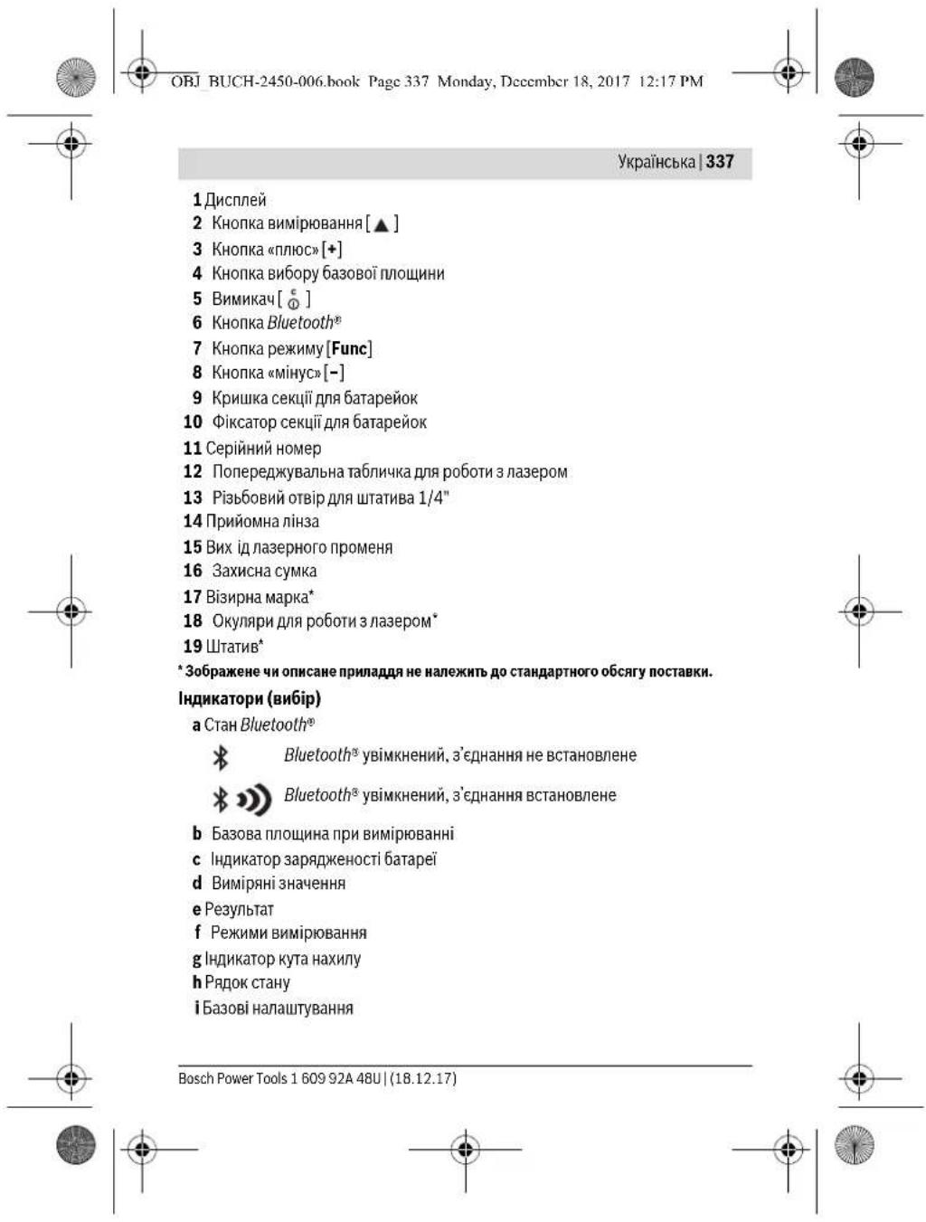

OBJ BUCH-2450-006.book Page 339 Monday, December 18, 2017 12:17 PM


YkpaHcbka339
po60TOI 3 npHJADOM o6OB'3K0BO IpeBepiTe TOHICTb PO6OTN pHJADy (INB. «PpeBipkA TOHOCI BYMIPIOBAHN BIDCTAHI", CTOP. 349).
BMnKaHH/HBMnKaHH
- Uo6 yBIMKHyTH BmIPOBaIbHn IHCTpyMeHT Ia3ep, KOpOTKO HaTCHITb Ha KHONKY BmIPOBAHHA 2 [ ]
Ioo6yBIMKHyTN BmipIOBaJIbHm IHCTpyMeHT 6e3 na3epa, KopoTko HATCHITb Ha KHONky yBIMKHeHHB/BIMKHeHH5 [0].
He cnpmaOByte na3epHn npomIHb hAIOe i TBapHn i He dmbitbcy na3epHn npomIHb, BKNIOaOHn 3 BenKOi BiCTani.
UoB BMKHyTH BHMIPHOaBbHm IHCTpyMeHT, yTPMMyTe KONky yBMKHeHH/BMMKHeHH5 [C]HaTCHyTOI.
Ypa3i BmKHeHHBIMPiOBAIbHOI hCTpyMeHa 3HaueHH,IO 3HxAoJrbcB nam'Ati, I hanaHTyBaHHI hCTpyMeHa 36epiraTcb.
OBJ BUCH-2450-006.book Page 340 Monday, December 18, 2017 12:17 PM


340 | Ykpaɪhcbka
Bn6ip 6a3oBoI nnoouHH (DnB. Man. A)
PnBmipioBaHHi BMOxTe Bm6paTn OHy 3 TpbOx 6a0Bnx PIOuHn:
3aHnKpaBmIPbOaBbHOIOhCTpyMeHTy (HaPp.nPiNpIcTaBHeHHoCtIH)
- nepedni kpaBmipobaIbHO npnady (hnp.. npBmipobAHHi BID kpaO cTOnA),
- cepeHnHa p3b0BOrO OTbOpY 13 (Hanp.,IIN BmIpOBaHb 3i WtATHBOM).
Дя Вьбору 63060IПОИMHNHaTCHINITb KONKIOY 4.KHONKHO3 [+]abo KONKHO
8[-],a6oKhONKO4 06epiB 6aKaHy 6a3OBy nIoUHHy. Iicna KOWHO rO yBMKHeHHr
BmipobabhoIhCTpyMeHTA BAKOCTI 6a0BOI IIOUHN BCTAHOBIOETBC3aHIN KpaBmipobabboHO IHCTpyMeHTA.
Meho《OchOBHI HAcTpOiKN》
Uo6 noTpanHTB MeHO 《Ba3OBI HanaHTyBAHHRA (i), ytpHMyTe KhoNky 7 [Func] HATCHYTOHO.
06epitbBIDNObiHe 6a3OBe HanaWtBaHH i BnaChe HanaWtBaHH.
Uo6BmTH3MeHIOBa0bIHaIaWtYBaHHa,HATNCHTbHaBMnKa45[
PiicbivBaHnHaucnne
IiDcBiYBaHHH DnCnner NoCTIH NOyBIMKHyTe. Akuo HIAki KHONK He HATNCKyObca, iDcBiYBaHHH DnCnner 3MeTOIO 3aOuaXdKeHH6BaTapeHOK/akymyNtOPHX6BaTapeep np6bl. Upee3 20 C TbMaHHe.
BmipioBaIbHi fynKuII
BmipioBaHHdoBXHH
06epitpeKHM BHMipIOBaHHHOBKNH H
UOb yBIMKHYTN JaepHn IpomHb, KOpOTKHaTCHiTb Ha KHONKY BHMIPBOHHA
2[
Uo63dHCHINBHMIPHOBAHHA, KOPOTKHOHTHCHTb Ha KHONKY BHMIPHOBAHHA 2 [ ]
Bmipnene 3naeHHB iDobpaKxTcBaHa nCnnei.
KoHoro noaBwO RO BnMPOBaHH, 6yNb nacka, nobTopitb
Bm780Bk3a9iKpOKn.0ctAHHe BmipHHe 3HaueHHB iDopaxyTebCn Ha
8.890 m DnCnnei 3Hn3y, NepeoCTaHHe-HaH HmI T.D
10.160m
11.430m
160992448U(18.12.17) Bosch Power Tools


OBJ BUCH-2450-006.book Page 341 Monday, December 18, 2017 12:17 PM


YkpaHcbka341
TpBane BmipobHn
PnTpBAnOMy BmipOBAHn BmipOBAhBn npnaD MoKHa nepeCyBaTH BIDHO Cho nui, BmipHe 3aueHHA kTyani3yctbC np6n. K0kHi 0,5c.Bn moKTe, Hap., nepeCyBaTHCa Bi CTIN Ha 6aKaHbY BiCTaHb, aTyalbHa BiCTaHb 3aBKn BiIO6paKaCTbC Ha DInCnneI.
06epiTppeKHMTPnBaIOnBOBmIPHOBAHHH
Uo6 yBIMKHTn IaepHm npomih, KOPOTK HaTCHiTB Ha KHONKY BMMIPOBAHH
2[▲]
IpecyBaTe BmipioBbHn npnaDtoTHnp, nOKn BH3y Ha dncnei He BcBITnbCHe 06xHa BiCTaHb.
KopOTKe HATNCKAHHa KHONKY BHMIPBOAHH 2 [ ] nepePBnBae
BKMTPNBALOROBHMIPBOAHBA. BMIPRAE3HAueHHA
11.623m BIDOpbaxyTbc3H3yHaHcNJIe.MakCmAlBeH MiHIMAbHe BMIPARH3HAueHHB iDIObpaKyOHTcHADHUM.NOBTOPHE HA KHONKY BHMIPBOAHH 2 [ ] NOOHAc HOBE TPNBAE BMIPBOA
TpBaJIe BmipIOBaHHaBtOMaTHUHO BmHKaETbcaYepe3 5 XB.
Bmipobanha nnoi
06epitbpexHKBMHHIPOBHNNIOO
NcIyIbOIO No Uep3i BmIPnHte WpHny I OOBHHY,IK npn BmIPIOBAHHI OOBHHM. MIXobOMa BmIPIOBAHHAMn NaepeHn pPOMIHb 3aIIuAeTbCn yBIMKHeHM. BiDpi3OK,IO BmIPIOCTcb,6hMaac Ha IHdkaTOPi BmIPIOBAHHIIOU
Pepie BIMIPHRe 3HaueHHB BIDOpbaxyEbycRa Ha DnCnnei 3BepxY.
No 3aBePueHHI dpyrOBO BMIPIOBAHH NIOua ABOTMauHO
BHPaXOByEBycR i BIDOpbaxyEbycR. KIneBHe pe3yNbTaT
BIDOpbaxactbRa HdNcPiE 3Hn3y, OKpEMi BIMIPIOBAHI 3HaueHHA -
HaHMM
BmipobaHaHa 06'Emy
06epitbpexnBMmipnoBaHHo6my
Iicra ycbrno no cep3i Bmipnre shpHny,doBxNHy i n6hny, k npn BmipobAHni DOBxHH. Mix cmmn Tpbomb BmipobAHnnaepn npomih 3aHnaaetcbyBMKHeHH.M.Bip3OK,po Bmipocctbca,6nMaac Ha iHnKaToPi BmipobHHo6Emy
Bosch Power Tools 1609 92A 48U| (18.12.17)


OBJ BUCH-2450-006.book Page 342 Monday, December 18, 2017 12:17 PM


342 | YkpaIhcbKa
1474.8m3 HADHMM
Hempame BmipkoBaHH BiDcTahi
HenpRME BMMIPIOBAHHBicTaHI MOXHA 3IiHCHOBaTHB Tpbox pexHMAX BMMIPIOBAHH, BAKHXMOXHA Bn3Haayu piHi BicTaHI.
3a donomoro HENpAmo BHMipOBaHH BiDcTahi MOxHbMMIPBOAti BiCTahi, RkHe MOXHBAHMIPITHPnPMHMMIINXOM, AKUHO HA TpaEKTopII PmOMeHr IChye nepeuKoDa a6o hemac uBoIO nobepxHI, kA 6 cnyBana B KOKCT peFneKToppa. LcNcicBbMIPOBaHH MoxHa 3actocobyATnHlWe B BepTKaIbHOMy HApRMky. Byb-ike BiXnEHHB Ropn30HTaIbHOMy HApRMky np3BODntb Do NOMINOkB BMIPOBaHHI.
Bka3iBa: Henpme BmipioBaHH BicTaHe 3abXm MeH ToH He Hx npme.
Poxh6kH BmipioBaHH MoKytb, 3BaKaouHn Ha cneuHkiy 3actocyBaHH, 6tHn
6bluHMn Hm npn npmomy BmipioBaHH BiCTaHe, dnn 36bnweHH TOnHOCTI
BmipioBaHH Mn padmo BmKOpHcTObyBaHT WtATNB (npnHa)
Bnepepbmi kOKePMMN BmipOBaHHMn NaepHn npomHb 3aHwaetbcyBMKHyTM.
a) Henpame BHMipOBaHHBHCOTN (Hb.MaB.B)
06epitbpexHM BmipobAHn HBCOTn. Cnkyte 3a Tm, uoB BMipobAihn HCTpyMeH 3haxOdBcHaTt cami BcOTi, uo HxHHTo4bAMipOBAHn. IOTIM HAXNITB BMIPOBAHn HCTpyMeH n BiHOeHHIO do baoBoI NooHHu BIMiprTe BiPioK 1a, Ra ce pOboHbcr y pa3i BMIPOBAHn DOBXKNH (HaNCneI npedctanEHO uepBOHOo NiHcIO).
14.142m
b)IodBimHe Hnpe BmipHOBaHH BHCOTH (IMB.MAN.C)
BmipobanbHH iHCTpyMeHT MOKe HnpeMo BmipobatN yci BiJpi3K,IO 3haxoTbCByBepTKaBHI NPOUH BmipobabHoro iHCTpyMeHa.
1609 92A 48U| (18.12.17) Bosch Power Tools

OBJ BUCH-2450-006.book Page 343 Monday, December 18, 2017 12:17 PM


YkpaHcbka343
06epitpekHIMnoBiiHoro HnnpMOrBO BmIPBoHaHHBcOTn
BmipaiTe, kipn BmipioBaHHIOBxHH, BiDpi3Ku 1Ta 2B 3a3haeHIN noCniobHOcti.
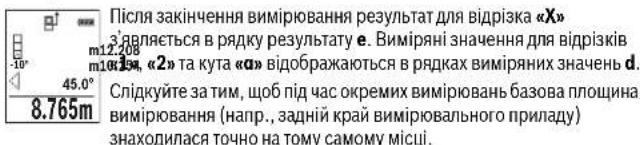
c) Henpme BmipobAHn DOBxHH (INB. Man.D)
06epitb pexHM HENpAMOROBIMIPIOBAAHH DOBXHH
Cnkyte 3a TMM, uo6 BMIpOBAhBnH npHnad 3haoDnBCra Ha odHn iTt cami BHCOTI, uo I TOCA BmIPHOBAHHA, kY Bu BNHaACAe. HaxnITb BmIPoBAhBN npHnad BiHDACHO 6a30BOI nOuHN Ta BmIPrRe BIcTaHb 已 _ 己 , kNpHnB MmIPoBAHHIOBKNHH
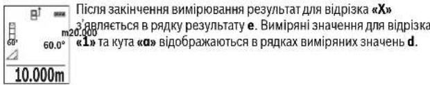
BmipobhaHnnoi CTIN (mB. Man. E)
BmipioBaHHn nnoi CTIN Do3B0nE Bn3NaHTn 3aIaBHy nnouy DeKinbKox Okpemnx DInHOK, 0o MaIOb ToHaKOBy BnCOTy.
YHabeEHOMpynKladi Heo6xidno OTPMaTH 3aRaIbHy PNOuy DeKInbKOx CTIH 3 ODAKBOIO BHCOTO H,ane p3HOIO DOBxHOIO L.
06epitbpexHKBMHmipbAHHHnlouiCTIH
TOMipIe BHCOTy KIMHATn H,IK ue pO6b7c8 y pa3i BmIPIOBAnHn DOBJKHH. BmIPIa 3haueHHaBIo6paKaCTc8aY bepXbOmy prkky. Na3ep 3aIIuHaCTbcra YBMIXHEHM.
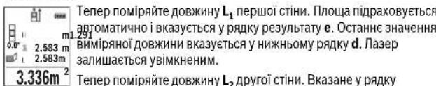
Bosch Power Tools 1609 92A 48U| (18.12.17)


OBJ BUCH-2450-006.book Page 344 Monday, December 18, 2017 12:17 PM


344 | Ykpaɪhcbka
DOBxHH L.CyMa o6oX DOBxHH (BIIObpaKaetbCycepeHbOMy pRky BHMIPRHX 3HaueHb d) NOMHOxytbcra H36epeKeHy B nAm'rti BnCOTy H. 3HaueHH 3aRaIbHOI nnoui BIIObpaKaetbCy pRky peSyIbTaTy e.
MoXHa NOMIPATN 1e 6yIb-ky KINbKICTb DOBXHH Lx, kI aBtOMaTHHNO IdoAHTbc i NOMHOKYIOCTBA H BNCOTy H.
I npaBnHbHO BmipOBaHHn Nnoi Heo6xio, 06B Bmipna nepwa doBkHa (ynpknla i - BncoTa KimHaTH) 6yna identmuhoDny ycxkOeMnx nlou.
PexHM po3mITKn (DNB. Man. F)
y pexmip03mitn noctiHO bIDmipiooTbCBAkazaiHO doBXHHN (BIDCTAH).LIOdoXHHM MOKHNApeHOCHTnHaNOBepxHNO,napn.,DIIbIP3AHN OHAKOBHX BIDPIKIB MATEPIAYaOboMOtaxy kapkana drrincoKAPTOHHO o6hBNKMOHN HMIIMANsHbDOXBHHcKnIacd01M,MAKCHMNbHA DOBXHHa CknIacd50M
Bka3ibKa:YpeKMIPO3MIKNBIIO6paXaCTbCBAIDCTAHBOIO3HauKHHaIHCnneI. OIOHO TOOKHO E KpA BIMIPIOBALHO ICHPTymeTA.
06epitb pezHM po3MITKN
BkaKtB 6aKaHy DOBkHy. JIa IbOro KhoNko7 [Func] o6epiB biIOOBHy UΦpy/po3prI 3MIHtB 3HaueHHa KhoNko3 [+] a60 KhoNko8 [-].
YBMKHITbpeKHMPO3MITKNKHOIIOBOBMMIPOBAHH2[▲],iNOBIbHO BIDaJIHTeCBAID NOATKOBOI TOHN.
BmipobbHHHnIhctpyMeH 63nepepeBHO Bmipioe BiDCTaHb Do
NoatKBOIO TOCHN. Pn bOmy BI0dpaKaIObC BA3aHI DOBKNHN Ta
IOTOHNE BmIPiPe 3HAueHHB.Bepxra aO HNKr CTpINA BkA3y Ha
HaMeHUY BIDCTAHo DAcHTynHO aO MHNyoBIIMTKH.
Bka3IBKa:KIOO NID AC TPNBaIoro BHMIPIOBaHHaTHCHNYKHOKNKY 4,MOKH3a4aTN BIMIPRHe 3aueHHB KOKCTI BKA3aHOJ DOBXHHN.
KoepdiicnIbOpnyBkA3yc, CklnsKa pa3iB 6ynaDocRhyta BkA3aHa DOBKNH.3enei cTpiKnO6auiuNcniin BkAYot hAdoCtREHNH Hne0e61HOIO DOBKNHII BIDPi3ka, UO BIMHaTe5c.
UepBoHa cpiika afo uepBoHa n03Hauka BkazyIOTb fakTuHe 3HaueHH, RaIO eTaIOHHe 3HaueHH 3HaXoIDtbc 3a Mekamn DmCnner.
BmipobAHHa KyTb Haxnly/UnpObn Batepna
06epitbpexHM BmipHOBaHH KyTb HaxHy/UnpOBO rBatePnaca . BmipHOaBnH INCTpyMeHT aBTOMaTHO HepeMHaCtbcMIX UMM DBOMa peKIMAMH.
160992448U(18.12.17) Bosch Power Tools


OBJ BUCH-2450-006.book Page 345 Monday, Deccmber 18, 2017 12:17 PM


YkpaHcbka345
LdppoBn batepnc ncyre jna nepeBipKn ropn3oHTaNbHcOti nn BeptkAaNbHocTi noJoozehnHa 6'ekta (Hanp., npalbHOI MaunHH, xoloDJIbNka toio).
YpaiznepeBnueHnna Haxnny 3'KynbKaHa DcNneI rOpHTb YepBOHm.
PekHM BmipobAHnKyTa Haxnny cnyrye nBnH3aueHHn iNIMomy a6o haxnny (hnp.,cxOIOBX xIDHB, npuynHIB, npi nIroHni Me6nib, npn poknaadnHi ty6 toio).
BaoBOIO NIOUHOIO DnB BMIPOBAHH KyTA HAXNY E iBNI KpaB BmIPIOBAIbHORIO IHCTPMEHTA. IKIO NiD VAC ONEPAUII BMIPOBAHN MIRAE IHINKATOP, TO BMIPOBaIBHNI IHCTPMEHT3AHAITO CXHNHEHBI6IK.
Функii nam'rti
3haueHHa6pe3yIbTaKoXHOrOOKpemOrOBmipIOBaHHa6epiraTcBnamrABTOMATHQHO.
Biodo6paaxeHH36epexeHHx3HaueHb
BnKlnKaTH MoXHa He 6IbSe 303HaueHb (BnMipAHHx 3HaueHb a6o KInCeBHX pe3yIbTaTIB).
Obepitb fyHKui npam'ati
3BepxyHaDnCnei BiObpaXyETbC HOMe KOMIPKN namTIT,3HN3y- m6. 300 BInOBINHE 36peXeHcE 3NaueHHa a 3NBA-BiNDOBINHpeXIM 8.7.620m BHMipIOBaHHa. HATNCkaiTe KhoNky 3 [+].IIO6 npokpyuBaTH 36peXeHcI 3NaueHHa 430.16m BnepeJ.
HaHcKaIe KHOky 8[-],IO6 npOkoPyUyBaTH 36epEkeHi 3aueHHaHa3a Raio y naM'ari HEmac 3HaueHb, 3HN3y Ha dncnnei BIDoopaKyETbcra 0.00 3BepxY -08.
HaNCTapiIe 3haueHHH 3haxOHTbc y na'MrI HOMep 1, HaHOBiE - HOMep 30 (Akuo c 36bepekehenx 3haueHb).PnH 36pekehenHi HOBO r 3haueHHa 3abXdn BNDaJIETBCaHaNCTapiIe 3haueHHH.
CtpanHHBmicty na'nti
IOnOuHHeHH3MCTy naTtHaTHCHtB Ha KHONky 7 [Func] i o6epitb dyHKUIO naTt .NtIM KOPOTko HAChCHtB Ha KHONky yBIMKHeHHBMMKHeHH5 [ ] 106 BnDaHTn BiOpbaKeHe 3HaueHHa.
ypaOndHocAChOrHaTHCKAHHHKHOHN4IBHMHKaay5[0]BndaIaNIObCyrci 3haeHH,uo3hAxOJrTbCrynam'rti.
Bosch Power Tools 1609 92A 48U| (18.12.17)


OBJ BUCH-2450-006.book Page 346 Monday, December 18, 2017 12:17 PM


346 | Ykpaɪhcbka
Iodabahn/HbjHimAHn3hauehb
Bmipnhi 3haueHHa 60 kiueBi pe3ynbTaTH MoKHa doJaabaTn a6o BiHimat.
Ddaabannn3nauehb
YhactynHompynKnadnoaactcbcOnncdoabAHnnIooBnHaTe nioo y3iDHO 3 po3dINOM (BmipOBAHnHnOoi),nB. cTOp.341.
HaTHCHITb KNONy 3 [+]。BIDo6paKaIbTcNipPaxOBaHa NIOUaI CUMBOI 工 + . HaTHCHITb H KNONy BIMiPBOAHHr 2 [A],IO6 pO3IOuATn HOBE BIMiPBOAHH NIOU. BImhaute nNOUy 3riHO 3pO3INOM «BIMiPBOAHH NIOU,HB.CtOp.341.OpOa3y no3abepenHi DpyrOTo BIMiPBOAHHpezynbTat dpYrOTo BMiPBOAHH NIOU i BIDo6paKaETCBa H NKHI 占CTHHI DCNIIe.ДЯ BiDio6paKHe HKNIE KINCEBO rpe3yblTaTy ue pa3 HaTHCHITb KNONy BIMiPBOAHH 2 [A].
BkaibKa: y pasi BHMipIOBaHn IOBxHnpezIbTaBIOobpaKaetcbcO npa3y.
Bidimahnhaueh6
106BHKoHaTN BIDHIMAHH3HAeHb, HATNCHTb KHONky 8 [-].PiOaNbwi iii anorigHiI DOnaBaHH3HAeHb
CTnpaHHBnMipHnx3HaueHb
KopOTKo HAHTCHBYHn HA KHONKY yBIMKHEHHB/HBMKHEHH5 [ ]BycixpeKHMAX BMMIPOBAHHMOKHBAJNTN OCTAHNC OTPMAHE BMMIPOBAHe 3HAueHH. DeKInbKOma KOpOTKMn HAHTCKAHMR HA KHONKY BIMKHEHHB/HBMKHEHH5 [ ] BMMIPOBAH3HAeHHB BNDANHOBTBCy 3BOPOTHMY NOPADKy.
3mHaOdHHuBmipoBaHHa
y6a3OBHX HalaHTyBaHHX OINHnueBO BmIPoBAHH BCTaHOBneHN «m» (MeTp). yBMKHITb BMIPoBAIbHH INCTPYMEHT.
YTPMMyTe KNONky 7 [Func], 06peeHTB MeHIO «Ba3oBi HanaTByBaHHA».06epiTb «ft/m»
HaHCHIb Ha KHOJky 3 [+] a60 Ha KHOJky 8 [-], 106 3MIHTN OHNHIOBMMIPIOBAHH.
Uo63aHmHTnIyHKMeHIO,HaTHCHITbHaBMnKau5 [c]。PiCIABMMKHeHHBmIPoBaBbHOI hCTpyMeHTyO6paHE HanaWtBuHHa3nnuactcb3epeKeHHM.
160992448U(18.12.17) Bosch Power Tools


OBJ BUCH-2450-006.book Page 347 Monday, December 18, 2017 12:17 PM


UkpaHcbka347
Intepfchc Bluetooth
Ipepaa daHnHa iHni npnai
Bmipobanh h nhtpymeht obnahn anmmyen Bluteoth9, knn dozboane nepebaatn da hi z anomoroio radiotexhkiHa naeki moibn bi kiuebei npctpo 3 iTepebcom Buteoth9 (hanp. cmapfoHH, pnahuetNHKn).
Hbopmaio 10oO cncemnHex npeyMOB nra 3'edhaHHa Bluetooth mB. ha caTl Bosch www.bosch-pt.com
BilshdoKnaHaHΦopMaui3haxoHTbcnHa cTropiui npOyKy Bosch,INB. QR-KoI,ctop.8.
PnnppepaDahnx Hpe3BleothoMOKNBI 3atpMHMK MIX MoiBbHM KHeBIM NpCTPOcM I BIMIPBOBAHbIM INCTPymeTM. C MeKOE6yTN NOB RAe3 BIDCTAHHO MIX OMOA pinnADAM afo i cAmHM BMIPBOAHM06 kTOM.
Akhbaia InTepeCy Bluetooth® dna nepepaHHaMo6InbHn KInceBn npctpi
IaakTbaui intepfeyCy Bluteoth@ HATNCHTb Ha KNKny Bluteoth 6Ha
BmipBOabHOMy IHCTpyMeNTi. IaakTBAUUI CHTANY Bluteoth ue pa3 HATNCHTb
Ha KONky Bluteoth6 a60 Ha KNKNY 3 [+] BnEBHTCB, 10 intepfeyc Bluteoth
Ha Baowmy MobinbHomy KINJEbOMy pnpctpoi akTbOBAHNI.
IINNOINHnHO Hcary FyHKm MObInHoRIO KINHeBOrO npCTPOIO IINCPOUeHHN
OBpOKn DAHNx pnoOnHyTOBc CneiaJIaNIIaKuB Bosch (AppS). B3aJeXhoCTi BiD
KINCeBOrO pncTPOIO XMOKHsCKaATy BVIDNOBIDHX MaraHnx.
Iicna3anyckydoataky Bosch BcTaHOBIOeTbC8a 3'HaHHaMIX Mo6iNbHM KInueBHM npnCTPOeM I BMIPoBAhHM IHCTpyMeHOT. RaUO 3HaJNeHO deKlNbKa AKTHBNHX BMIPoBAhHX IHCTpyMeHIT, BNBePitb npHaTNNBIMipOBAhNBH INCTpyMeHT 3a cepiHNM HOMepom.
CTAH3'EDHAAHIAKTHBHE3'EDHAAHAA(a)BIIObpaKaiaOTbcyPRAky CTAH(y) BHMIPBOAbHBHO IHCTPYMHTA.
DaekthBaiai InTepeHcy Bluteoth
Ja daekmbaui 3eHnHb Bluetooth® HATNCHTB KHONky Bluetooth® 6. Lio6 BmKHYTN CnHAN Bluetooth®, ue pa3 HATNCHTB HA KHONky Bluetooth® 6 a6o Ha KHOKNy 8 [-] a60 BmKHTB BMMIPOBAIbHH IHCTpyMENT.


OBJ BUCH-2450-006.book Page 348 Monday, December 18, 2017 12:17 PM


348 | Ykpaɪhcbka
Bkaizbkn 0doo po6oTn
BinbIoknadHaInphiopMaia3hAxOHTbcnHa cTOpHui npOdyKry Bosch,INB. QR-KoI, cTOp.8.
BHMipioBaIbHHI INCTpyMeHT O6nHaHn paoiHTeppeHcOM.3BaKaIte Ha MiceBi 06mExeHH, HAp., B nItakax a6o nikapnx.
3arabhi Bka3iBKn
PnHOMHaIIN3a14imCue BHXOyIa3epHOIpoMeHa15nIacBmIpOBaHHNobHHH6yTHBIDKpNTi.
IiIac BmHIpHOBAHHB MImHIpHOaBbHbHn IHCTpyMeHT nepeCyBatn He MOxHa. Tomy, 3a MoKBCIcTO, NOKlaIDb BmHIpHOaBbHbHn IHCTpyMeT Ha HepyXOMy ONOpHy NOBepXHo.
ΦaKToH BnMbBy Ha diana3OH BmIpIOBaHH
Padiyc BmipobAAH3 3aeknhtb Bid c0bitneHH iBd6hBOH 3daTHOCTiIbBOI noBepxH. Uo6 naepHH npOMH Byno Kpaue BnHO npCnHbOMy 3OBHIbOMy oocitneHH, Braatne naepH oknyrnp 18 (npnaad) i BkOpNCTOByte B3nHy Mapky 17 (npnaad) a60 3aHTH bINBOy nobEPXHO.
Φaktopn BnNBy Ha pe3ynbTaB BMIpObaHH
3BxaKIOUH NaIeMHNI EeKNTi, He MOxHa BnKIOUHTN NOMNIIH B p3eyNbTataX BmIPHOBAHH NaIb MmIPHOBAHH NaIa PI3HIX NOBepHXJ. CIOIN BiNDocrTcR: -npo3oi npoeBXHI (Hanp., cKNO, BOJa),
- noBepxhi, 0o BiD3epKaIIOIb (hAp., nonipobAHm MetaI, cKNO),
- nopncTI nobepxHI (hanp., 3oJauHmatepiann)
- ctpykTpyoBaHIO nobepxH (HaNP..ctpyKtpyoBaHa WtyKaTpyka, npnpOHH 6dyibEnbHN KAMHb).
3a Heo6xdiHcTb BNKOpHcTOByTe Ha TaKHX IOBepxHx B3nPHn 17 (npnaia).
PnKOCOMy HabeDeHHi Ha zijb MoXJIHBI NOMNIK.
KpimToro,Ha pe3ynbTaBmipHOBaHHMOxytB BnHbaTHIaPn NOBITPA3 p3HO TEMepatypopo aBO HENPME BiDaePKaIOBaHH.
IpeBipKaToHocTi Ta Kani6pyBaHHaN BnMIpHOBAHHaYta Haxnny (nB.Ma. G)
Perynpho nepeBipTe ToHCTb BmipOBaHHa Kyta HaxHy. Ye 3diHcOeTbcn
yIAMXOM BmIPoBAHHa B OBX HAnPMKAX. IJIbTO NOkNAdITb BmIPoBAhBNi
npnaad Ha CTIN Ta BmIPrHe Kyt HaxHy. NObepHtB BmIPoBAhBNi Ppnaad Ha
180" a 3HOy BmIPrAte Kyt HaxHy. PI3Hnua BiOppaKyBaHO rHaehn He
noBHnHa nepe6inbSyBaTH MaCk. 0,3°
160992448U(18.12.17) Bosch Power Tools


OBJ BUCH-2450-006.book Page 349 Monday, December 18, 2017 12:17 PM


YkpaHcbka349
Ypaai6iBnHx BIXINHEB BMIPIOBbHN IHCTPymeHT Heo6xHHO 3HOBy BIKANI6pyBaTn. Dn zuo o6epit CAL. DoepejkyTec BkazIBOK Ha DCNnei
IicnCnblnhx TemnepatynKoJIHbAHb i noTOBxIB MN padHMO nepeBipHTN TOnHcIb 3dINCHITN 3a HeO6xIDHCTO KAIbIPyBaHH BIMIPBOAbHOrO IHCTpyMeHTy. Iicn3MNIHemepatyn daite BIMIPOBoBbOMHy IHCTpyMeHTy CTabIN3yBaTn CBOHO TEMNEPATpy, npHI HIX dIIINCHOBATN KAIbIPyBAHH.
Ipebipka Touhocti BmipboBaHH BiDcTaHi
ToHicb BHMipObaHBOHO IHCTpyMeHTy MOHa NepeBipTH TaKHM YHOM:
BbepiB dianHKy DOBXHIOO np6bn.3-10 M (hanp..uHNHa npmiueHH, DEBPHN npop3), pO3MIP koi BAM do6pe BIDOMH. BmIPoBAHnMa 3diCHOBaTHc 3a cPnHTnBnx yMOB, TO6TO dINrKa Mae 3hAxOJNbCB n pniMIueHHi iCINbA NOBEX HBMIPoBAHnMa 6byt pIBHOIO iD6pe BiDdEprkALOBaTH.
- PpomipTe dianhky 10 pa3iB nocinib.
BIDXINHEHNOKPMEHX3HaueHb BHMipIOBaHb BiDcepeHbTo 3HaueHHa 3a CnPHNIBHX YMOB He NOBHNOpeBNUyBatn ±4 MM HA BCIN DINHUI. 3AnpOTOKONIOE BHMIPOBAHH, IO6 y MaHyTbMoMy MoKHs byno nopiBHTN TOUCHtB.
Pobota 3i WtataHbOM (npHnad)
UtaTHOOC6bNO Heo6xHn npo60ax Ha BenHKi BiCTahi. HAdInbTe BmIPOBaBnHnn pnpad p36bo1/4" 13 Ha WBNKo3MHy PnaCTHy UtaTbA 19 aO b3uHaHoro fOtoaTaTHa.PpIKpyTtB HorO FICKYouHM TBHTOM Ha WBNKO3-MHHI NtACHI.
HaTnCKaHHaH aKHOy 43aJaTe 6a3OBy nIoUHHy Ira BmipIOBaHb i3IitAHBOM (6a3Oba nIoUHHa:pi3b6a).
Tobidomnenna pno nOmnkn
KIO BIKOHaTHBIMIPIOBAHH npABHbHO HEMOKHBO, HA DCNnei BIDOppaKaetcbnOBIDOMNEHH pno NOMNKy EError).BIMKHITb i3HOBY BBIMKHITb BIMIPOBaHNNIHCPTPYMENT, NOTIM NOHTb BIMIPOBAHHAHO.

Bmipobabnhi nhtpymeht BicTeKye npabnblhnicbpo0tn np KoxHOy BMIPOBaHHI. PnBnBnEHHH enoNaKnHa HcNnei BiO6paKyEtbcA hue CMBOJI, 10 cToTb npOy, IBMIPOBaBnHI IHCTpymeHT BmHKacTbca. Ycbomy BNnAdky nepaTe CBNI BmIPOBaBnHI npnaadpeep3 MaraHN B cepBChy MaNTepHIO Bosch.
Bosch Power Tools 1609 92A 48U| (18.12.17)


OBJ BUCH-2450-006.book Page 350 Monday, Decembr 18, 2017 12:17 PM


350 | Ykpaɪhcbka
Texhihe 06cnyrobybaHHia cepbic
Texhiueo6cnyrobybannioounneHHN
3aBkDn TpImaTe BnMIPbOanbHn npnad B nCTOTi.
He3aHypoIe BmipobalbHn npna y bOy aO bHpiPiHN.
BHTnpaIte 3a6pydHene H BONoTOO M'AKOIO raHcIPKOIO.He KOpHcyTEcA MHHMn 3ac0amnip03yHHNKAMn.
IobpeDorTnAaTe 3a npHOMHOIO nIH3OIO 14. Haue6To ue 6yHn OKyIrpH a6o nIH3a foTOanapata.
HaCnnaTe BmipIOBaIbHn npHnad Ha pEmoHT B3axHChi Cymu 16.
Cepbic HanaHnKaoncynbTauioBnKOpncTAnHH npOyKu
Cepbcha MaIeTepHb BiNObiCtHa 3aIHTAHHa TcOcoBHO pEmOHy I TEXIHHOro
06cIpyOBaHHa BaHoro BHPyo. ManIOHKnB DetaIax IHΦOpMaJIO zoDo
3aIuaCTH MoKHa 3aHNI 3aApEcoK:
www.bosch-pt.com
KoHamaKnBpOb6TnKNBosch 3 hadAnHH KOChyNbTaJi uOdo BmKOpNCTaHH npOdyuii 3 zaoBoJeHHAM BIDIOBcTb Ha Baui 3aIHTAHH CTOCOBHO Hauoi npOdyuui Ta npIaNADNo Hei.
PnB BCx iDoaTkoBnX 3aHtHaHHx Ta 3aMoBnEHHi 3aHuaCTMH, 6yIb naCa, 3aHaauHne 10-3NaHn Homep IJr 3aMoBnEHH, IIO cToITb Ha NaCnpOpTHi Tabnui npOkykTy.
IapaHTiHe 06ClyrOByaHHI ipeMOHT enEeKTOHcTpyMeHTydiINCHIObCTBIDIOBINO do BmOr I HOpM BnToBnIOBaHa Ha TepHToPi BCIX KpaIH NIIuye y fipMOBHX abo ABTopn3OBaHN cepBcHNX cteHpax fipMN P06epT BoW).
IIONEPDKEHHI BYKOPHCTAHN KOHTpaKaTHOIpOykuII He63neueB E ecnnyatauij moKe MaTH eratuaHBH aHcnlKnAa 3doPob' BIROTOBENH I po3IOBcOJeHHI KOHTpaKaTHO IpOykuII nepeCniDyctcb 3a 3aKOHOM B adMIiCTpAHBHOmyipMIMHaBHOmy npdky.
160992448U(18.12.17) Bosch Power Tools


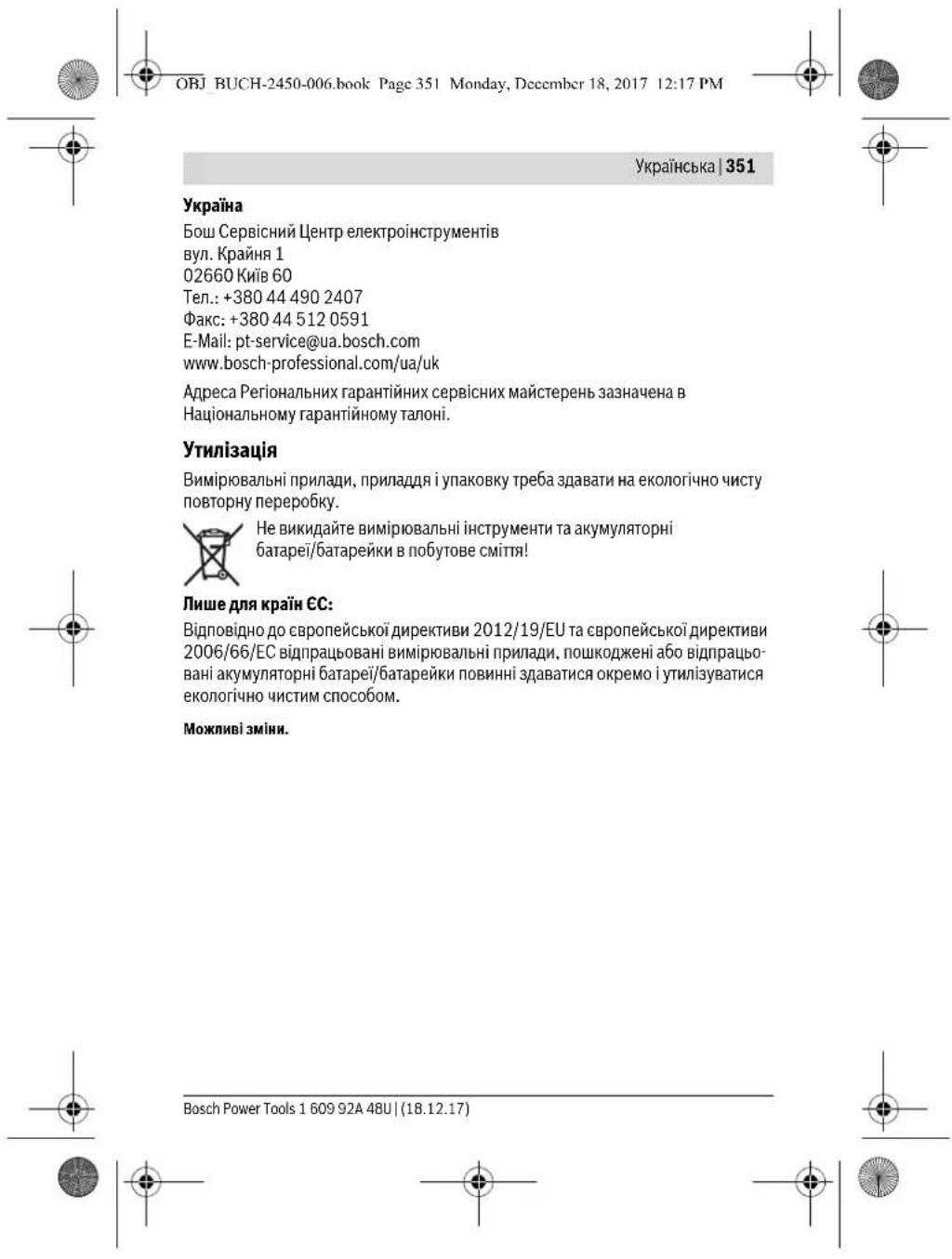

OBJ BUCH-2450-006.book Page 352 Monday, December 18, 2017 12:17 PM


352 | Kazakua
Ka3akwa
HdiyuHHHIM yIH KapaTbPfAH naaIaNALy KxKtaTapbHbH KypMaBHJa naIaIaNAY XeHHderi Ocb HcaybK, coBbMeH 6ipre KocbMuaIap da 6onyb MykH.
Caikecki pactay kaiblaknapa Kocbimwada 6ap.
Ohimdi eHdpireh MemneketTypalbaknapat HIMHH KopnycbHaKahe Kocbimwada
Kepcetiren.
EHnpy MepaH HcyckaybKthl coHf6 BeTHe KepeTInreH. NmnpTaybHa KaTbCTb 6aahnabc Manimeti Kantamada bepinreH.
Ohimdi nai danany Mep3imi
EHMHH Kbl3met ety Mep3imi 7 kbln. EHNipinre Hmep3imhen bactan (EHnpy KyHi 3aybI TaKaTaaCbaHna Xa3b1nFaH) icTeTne 5 kbln caKaTaHaHHa COH, EHIMdi TeKcepyci3 (cepBNTk TKcepy) naiDanaHy CbHbImaBl.
Kb3MeTKeH Neme NaIaAnaHyBbHk KaTeNikTepi MeH icTeH bHy ce6ntepinH ti3imi
EHIM KopnycbHAn TIKENEyTytH WbIKca,naJdaHaBaH3
JxaybH -uawbHKe3iHe cBpTTa (daana) naIauanHaBb3 KOpync iuihe cy Kipce KpybInfBiHbKocyub60MaHb3
UektiKyuB6nInepi
-0HIM KOpNyCbHbH 3aKbIMdanybl
TexHnKaIbIK Kbi3MeT KepeCy Typi MeH Xniniri
OpaandaHyaHcOH eHIMdi WAnHHaTaapTy YcbHbIaNbl.
CaKray
- KypraKJepde caKaTay Kepek
- KofapbI TeMnePepatya KeiHEn HKeHc CaynenePiH ecepH en aBic CaKaTay KepeK
- cakay KeiHne TemnepaTypaHBiKeHET aybIyBbIHAN KOpFay KepeK
erep Kypan JyMcaK cEmke HeMece INaCTIK KeHcTe KeTki3iCnCe OHbl OcbI e3IH Koprafbll KaBbHa caKaTay YCbHbInaBl - cakTay wapTAPbTy panaKocbIMa aKnapat any yuiH MEMCT 15150 (1 Wapr) KyaKaTbIH KapaHbI3
160992448U(18.12.17) Bosch Power Tools


OBJ BUCH-2450-006.book Page 353 Monday, Decembr 18, 2017 12:17 PM


Ka3akua 353
TacbImaJay
TacbIManay Ke3HneEhMnI KynatyraXaHe Ke3KeNreH MexaHkAnbIKbKnAn etYe KaTaH TbiBIM CaJIbHaJIb
6ocaty/kykTey Ke3iHne nakeTT KblcaTbH MaunHaIapDbI naJdaNaHyf pyKcat 6epinmei.
- TaBImaay wapTapbI ranaTapbH MEMCT 15150 (5 Wapr) KxKaTbH OkbHb3.
Kayinci3ik HycKaynapbl

Onwey KypalbH Kayinci3Xe HeceHIMdi naaDanahyuH6apnbK HcyKaynapbMyKnTOKbl, XyMbIc 6apbcHna eckepi3. Onwey KypalbH ocbl HcykaynpFa ca n naDanaH6ay enwey KypanbHaFb KipictipinreH Kayinci3dk uapanapbHa
XaFbIMcbI3 acep etedi. Onwey kypanbIHdafbI eceptynepdi
KepiHoeTIN KblMaHb3.OCbI HcCKaynAPBcI CAKTAn,0JIeEy KxPAJIbIH BACKJIAPFA BEPREHEOANPDbIOKAYCbIHbIHb3.
A6aB60bHb3-erepocbIepe6epnreNaananyHemeceTety KypanapbHaH baca Kypanan naananaHc Hemece bckxymbc adictepl opbnanca 6yn kaynti caynerw anhhyra anbin Kenyimykhi.
Ouwe KypaIbIe cKepeTy TaKTacbImE Hka6bIKTaIraH (Ouwe KypaIbIHbIcypTeIHde rpaФнka 6eTHe 12 HemipimEn 6enrInehRe).
IEC 60825-1:2014
<1mW,635nm
Laser Radiation
Do not stare into beam
Class 2 laser product .
ErepcepyXancbipmacbi ci3in eniH3 tinie 6onmaca, anraukbnai dananyanand anbHn OHbH opbHa ci3in eniH3 tinie 6onfah XancbipmaHbXab6tbpHbI3.
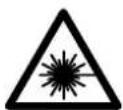
Jaep cayncin adam hemece xahyapnpfa 6afttamahb3
Xehe 6313 de tikehen eaehme 8aflnfa Napep cayncine
KapaMaHb3. Ocbnil aadamdpabHy Ke3iHaflpblpyi MyMKH,
Catc3 OkfanaPFA anbiny Keyni Xehe Ke3di 3aikmDny MyMKH.
Erep naep cayneci Ke3re Tycce Ke3depj Kymbl 6actb cayeneh apkapatyKepek.
PnapeKpybInbIbIcbIbHa eWkaHdAn e3repyTbI opbIHaMaHbI3.
Bosch Power Tools 1609 92A 48U| (18.12.17)


OBJ BUCH-2450-006.book Page 354 Monday, Decembr 18, 2017 12:17 PM


354 |KazaaKuia
- Na3ep Kepy Ke3inipirih Kopfahbiu Ke3inipiri petihe naaana6anb13. Na3ep Kepy Ke3inipiri nasep cayncicin kakcbipak Kepy yuih Kbi3met Xacaaibl, 6ipak on na3ep caynciHen Kopfamaibl.
Pnep Kepy Ke3inipirH Kyh Ke3inipiri petHne Hemece Kon Ko3ranbciba nainanana6a13. Pnep Kepi Ke3inipiri ynbtpaipnoet caynenepeHH tonbIK KOPramai peKepy Ka6nntiA a3aTadbl.
Θnuey KypanbH TeK 6InikTmMaHaFgAne apHaynb6nuekTepeMn XeHdTei3. Co npknBn eUney Kypan Kayinc3irin cakTaicb3.
Banap na3ep 9nwey Kypanb6aKbnaaycb3 naDanaH6acbH. Onap 6inme aamdappbH Ke3H WafbInctbipy MykHi
XaHabTbCybIKbTkap, r3aJap Hemece WaH XbInrA HApBInbc Kayni 6ap optada enwey Kypanbln naHanaD6h23. EneWey Kpypanbl yKbH bIbFapbl, WAnDbYxHAnDbPbIN, ePT TyDbPiBy MyMKH.
A6aB 60nblb! Ouwe Kypanbln Blotho6 Ben naDanahyda 6acKa Kypanlnapen Hxa6blkTap, ywak Xane MeunHahnbKypanlnap (Mbicanb, KapnOCTMnYPOT, ecy Kypanlbp) kymblbHa Kepeprine npna 6onyb Mymkih. CoDaan-akXakbiH TpyraH aamdpn MeH xayahdpa3nHn Tybpy KayinTOnBik XOIO MymiK imec. Ee Kypanbln Btlooth6 Ben MeunHahnb Kypanlkap, Xapah Man 6eTepe, XmmHbnKxabkTAP, Xapbny Knyi 6ap Xane KxpblatIn h AmaKTap XaHbIg Na ndaNaHbI3. OIwe Kypanbln Btlooth6 Ben YwakTApda Nau danAnb6bI3. DeHere KaBln anMaKaTa y3AkYakIt naidanaH6AbI3.
Bluetooth® ce3 genrici cypet 6nricimeh (norottnrep) 6ipre Bluetooth SIG, Inc KOMANHRCbHbH, tipkenren TAYapnbK genrici XeHe MyNirI 6onbl Ta6bnadbl. Ocb1 ca3/cypet GenriciR Robert Bosch Power Tools GmbH apkbln naDAnany nuehern herisine opbnndanabl.
Θhim XΘe Kbl3MeT CnnaTTaMaCbI
Onwey KpyanbHcypetibap6betiaaBn,naDanaHyckaynbHOKyKe3iHe OHblaaBikYCTaHbI3.
TaFaiBIndany 6oBbHwa KOnDaHy
Onwey Kpyanbl KaawbKtBkTAPdb, Y3bHnBkTAPdb, 6MkiTkepi, apaBkTAPdb, Kenbeynepdi enweye re Xane ayeaHaAe ayMaKtapdb ecenteyre apHanFaH. Onwey HtAnKeepin Bluethop 4ApkBnB 6acka KpybnBnnapfa Etki3y MymKiH.
160992448U(18.12.17) Bosch Power Tools


OBJ BUCH-2450-006.book Page 355 Monday, Decembr 18, 2017 12:17 PM


TexHHKanbIK MAnimetTep
| Сацлы пазер кашьктук онлайнiwi | GLM 50 C |
| Белем hemipi | 3601K72C |
| Белowie aiMaftby (адеттeri) | 0,05-50 M A |
| Белowie aiMaftby (адеттeri, калайсыз karлдя) | 20 M B |
| Белowie anbikтуг (адеттeri) | ±1,5 MM A |
| Белowie далдг (адеттeri, калайсыз karлдяда) | ±3.0 MM B |
| Ен kiш i керсетин сеlement | 0,5 MM |
| Жанама кашьктук онлайн мен днгrei | |
| Белowie aiMaftby | 0°-360°(4x90°) |
| Калбeydi онлайн | |
| Белowie aiMaftby | 0°-360°(4x90°) |
| Белowie anbikтуг (адеттeri) | ±0,2C/D |
| Ен kiш i керсетин сеlement | 0,1° |
| Жannы | |
| ЖуMbIC temператypасы | -10°C...+45°C |
| Сацгay temператypасы | -20°C...+70°C |
| Сальстымы aya bilingdьfы мак. | 90% |
| Пазер сынblы | 2 |
| Пазер typi | 635 HM, <1 MBT |
| Пазер саунесинддаметри (25°C Te) | |
| шамамен. | |
| - Кашьктугы 10 solfahanda | 9 MM D |
| - Кашьктугы 50 solfahanda | 45 MM D |
| Белучу abTomatн��асышамамен TemeHDerigideh coH. | |
| - Пазер | 20 c |
| - Белowie kypалы (алшевсí) | 5 МИH H |
| EPTA-Procedure 01:2014 Кужатына саïrelamы | 0,10 кr |
| Калемер | 106 x 45 x 24 MM |
| Корfasныc typi | IP 54 (шан кенишамырайтынсudан корfasны F) |
Bosch Power Tools 1609 92A 48U| (18.12.17)


OBJ BUCH-2450-006.book Page 356 Monday, Decembr 18, 2017 12:17 PM


356 | Kazakua
OBJ BUCH-2450-006.book Page 357 Monday, December 18, 2017 12:17 PM


Kazakuaia 357
7ФyHKUAnbIKnepHE[Func]
8 MInHyc nepheci[-]
9 BaraperaBenimi KaKnafbi
10 Batape 6enimi KaKaNaFbHbH KynIb
11 Cepnabik Hmip
12 Na3ep eckepTy TaKTabci
13 1/4"uTATMb6ypaHdacbI
14 Ka6binyay nH3acsb
15 Na3ep cayncinH ibfbcbi
16 KopfaiTbIH KAnTa
17 Na3ep HbIcAHaBik TaKTaCbi
18 Naερ κεργ Κεπίπιρι*
19 TaFAH
*BeyeneHReH Hemece CnnaTaanFAn Xa6bukTap cTaNapTTbXeKtki3y KEnemimekamTbnmaIbl.
Kopctkiw 3neMeHTeP (taHaMaIbI)
a Bluetooth8 Kyyi

Bluetooth® 6enceNi, 6aHnHc JacanMaIbI

Bluetooth® 68e9cHd, 6aHbAChzacabdi
b 0nwey heriri x3a3blTb1fbl
c Batape KepceTkiu
dThnueyKeIeMepiXkonaFbI
e HatakepeKoana
f Othuey dykuhnaapbI
Ehic6ypbibbHbHKpcetkiu
h Kyu naheni
i Herisri napemtprep
XnHay
BaTapeaIapIbIcany/aImaTcbIpy
Onuey Kpyanbyuih ankanin Maprae6ataperaeh Hemece akymyntopbH naIanaHy cybHnabbl.
Bosch Power Tools 1609 92A 48U| (18.12.17)


OBJ BUCH-2450-006.book Page 358 Monday, Decembr 18, 2017 12:17 PM


358 | Ka3aKaIIa
1,2BolbTbIKaKKyMnIaTOPMeH 1,5BolbTbIK6aIapennapFa cIbIcIbIpaHaJa KEMipeK eIeWeyneppi opbIHay MyMKH.
Batape 6eniminH KAKNAfbH 9 ayyuW H 10 bicpMaCbH 6acbl, KaKnAcbH uabHb3. BatapeHbHEmece akymyTOpdbCaNbHb3. Batape 6eniminH iuiHderi cyptTe KepcetireHne noIOCTapDbH dybpoc HpaHacByH kAmTaMcb3 etHj3.
Erep6oc6baperaenbenrici anbninncnnepe naa 60nca,ohda kheiam. 100 enwmeep 60nybmykH.Erep6baperaenbenrici 60bc60bnin,ksblntycte KaHCA,Onda eewip enwmeepdipoibhdaya 60mnaBb.Batapera Hemece AkyMynrto npnpdbI aMaCTbpyPiHb3.
Bapnikb batapeinap hemec e akymyrtopnpdbi bpde anmactbipnh3. Tek bip HdpinyinH kHe KAtbipdien batapeinap hemec akymyrtopnpabi napanadhnh3.
3aKyaBt nainanah6acab3,6atapenHb Hemece aKKymnTopnpdb 0neWey KypabihAn anbin Koibh3.3aKyaBt ktaKah 6atapennap Hemece aKKymnTOpnp tot 6acyjxHe sapaDbH JkofTby MyMkiH.
PaiDanaHy
Painanahya eHdipy
Kocynb3apraTay Kypanbln 6aBnaycb3 KaandpMaHb3 Xane enwey Kypanbln nainananydah coe wipih3. Naep cayneim H aamdpbH Ke3IH WafblbCTbpy MYMKIN.
Onwey KypanbIH cbI3dAH XHe ticKei KyH caynepeiHcKaTahbI3.
Ouwey KypaBHa AipbKua TemnepaTypa Hemece Temnepatypa tepBennepi ace tneYtnic. OHb MicaBb ABOKEnIke yak yaKbIT KaandpMaHIs. YnKeH TemnepaTpy TepBennepi XaFdaHbHa aanbImen enuey KypaBbTH NmepaTpaCbN Dpyctan coH naDanaHbHs. Aipykua Temnepatya Hemece TemnepaTpy TepBennepi Ke3iHde enuey KypaBbHIn dAndiir TeMeHNenyi MyMKIN.
Onwey KypaBih KaTbI cokkDah Hemece Kynaydah CaKaTHbI. CbIptKb KyuTl acepnpenH KeIH oNwey KypaBihH XMybcH KaIrafctbpydah anDbH apaBm dAnik TekepyiH opbHday Kepek ("KaBbTkbl EneyeiH dndirin Tekepey", 367 feTIH kapaBt).
Kocy/ewipy
OBJ BUCH-2450-006.book Page 360 Monday, Dcccmber 18, 2017 12:17 PM


360 | Ka3aKaJua
"Heriari napametnpep" M3pi
"Heri3ri napamertnpep"(i) m3pihe kipy yuih 7 [Func] nephecin b6aiby cTaHb3.
Herizrnapametpmen3iHnnpametpiH3diTaHaHBla3.
"Heri3ri napametnpep"Ma3ipireH uBHy yuiH Kocbi-euipy TyMecin5 [ 心 ]bacih3 nephecin 6acbH3.
Диспл徳жарыгbl
DnCnnJXapbIbH y3akYakbITKa KocBInFa. IpeH6acblmaca, dnCnnJXapbIFbI Wam.20cekyHTan coh 6aTepbA/Ha/akKMyrTOpBly HEmeeyuH KapaHfbNaHaDbI.
Oniwey yhknnnapbl
¥3bIHdbkTb onney
Y3bIHbIKTbIeWeyiTaHaHbI3.
Jaepcayncih Kocy yin 2 [ ] enwey nepheine Kbcka bacbhiia.
Onuey yuiin 2 [▲] onuey nephecin Kbccka bcbihla. Ouuy mHI TEmHe duCnneJe Kepcetinei.
KorapbdaRaKepeTinreKaamdpnApEeHriEnyuyiH 890m COnBfEnyMaHINnHnNTEmHeMeRHaBnDaTypaB,
10.160m 11.430m
Y3dikci enwey
YJ3ddi3eIyIeIyIeIyKpyIbIhHbCaHaFkBbIbTyfRa6oIaIb, OHJaIeUeYKeIeMl WAM.ep05ckyHdcaHbKaJaaPabId.MbcIaNb, KabIpbFaadKepeKt KaIbIKbTkka EtyIHJ MyMknK, KaIbIKbIKbTApdaIbM Kepey6oIaNb.
Y3diKci3 enweydi TaHaHbI3.
Iaepcaynecih Kocy yuih 2 [ ] neuey nephecihe Kbcka6acbiHb3.
Onuwe KypaBn KepeKTi KaBbTKbIK NcNneIN TeMeHr 6enirHne KepCetinreHue Xblkblh3.
11.623m Y3nkiC3 5MHHTAH COH ABOMTBI eWdi
160992448U(18.12.17) Bosch Power Tools


609 92A 48U(18.12.17) Bosch Power Tools


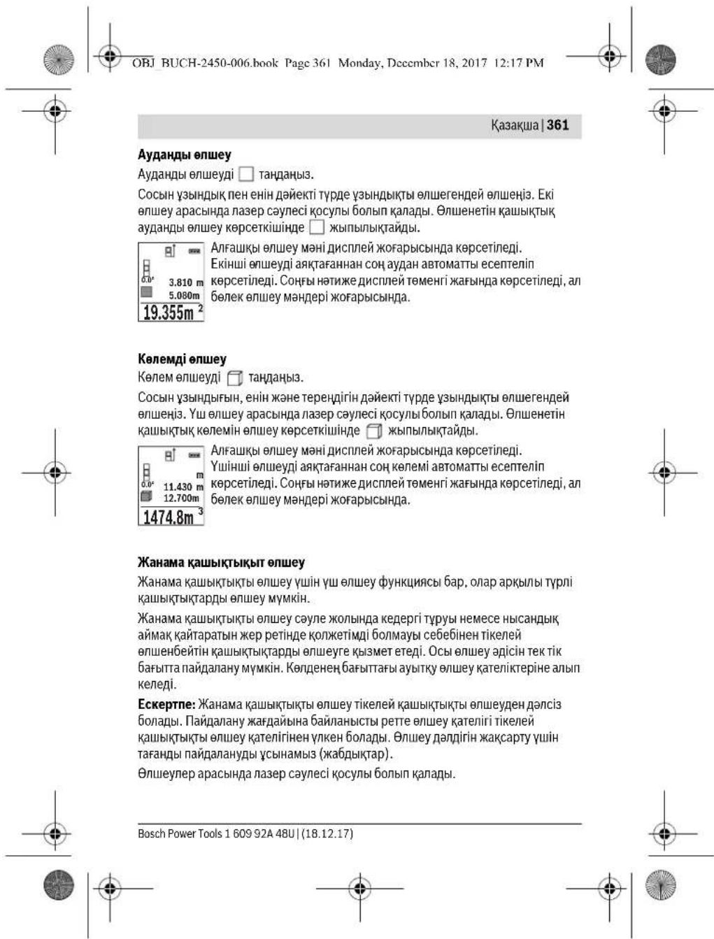

OBJ BUCH-2450-006.book Page 362 Monday, December 18, 2017 12:17 PM


362 Ka3aKaIIa
a) KaHama 6nIKrKi 0neuey (BCypetIH KapaHb3)
KaHama 6nIKTKIeIeeyi TaHaBHa.
Onwey KpyanbI TEmHri Onwey HnyKTeCImeH bip 6nkiKTIte 60nybHa Ke3 XeTk3IH3. Onwey KpyanbH Heri3r Jka3bIKbTKaH aHaNbIpbIN Ka7bIKbIKbTI "1" Y3bHbIKbTI onweHne OnweHiz (DncnnneKeB3bn Cb3bK petinhe KepcetinreH)
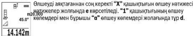
b) Koc kama 6niktikti enwey (C cypetih Kapa h3)
Onuwey KpyanbI OHbIH BepTHKaanDbI DeHReHHe KaTaTbH 6apNbIK KaUbIKbIKTapNbI KaHama onuweiy MymKIn.
Kocbi,kaHama6bnkxtri eniweydi TaHdahb3.
"1"MeH "2"KaalbIKtBkTAPbl Y3bIHbIKtB 0IeHeHcOcb IaKeTe HJH3.
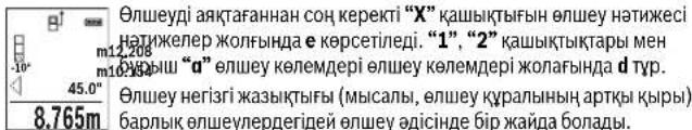
c) KaHama y3bHbIbKbI bIe Hwey (D cypetIH KapaHbI3)
KaHama y3bHdbkTbI onlweydi TaHaDbH3.
Onwey Kpyanbi 3dennre Hnyteim Hbip 6hiktke 60lybHa Ks3 kekTkiH3. Onwey Kpyanbi eriri KaabkTbKTAH aiHaanBbPin KaabkbTbKbTb Y3bHDbkbTbI enuweren ennweh3"1".
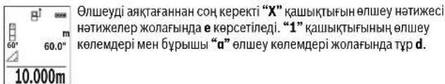
Ka6bipra aydaanbH enwey (E cypetin KapaHb3)
Ka6bpyaaydahbH enwey 6iphewe kannb6nKtIKI 6eK aynadapbln KocbiNbcbH ecenTeey Kbi3MeT eTei.
160992448U(18.12.17) Bosch Power Tools


OBJ BUCH-2450-006.book Page 363 Monday, Dcccmber 18, 2017 12:17 PM


Ka3akua|363
CypeTeriMbicanada6ipHee6nktiriH6ipdeBipakypni3bHdbkTB L Ka6bpFanapdbKannbaydahbcencntenei.
Ka6bpyaaydaHbHbnHnIeuydi TaHaDb3.
Bmme 6nKtirH y3bHdbkTb enweneren enwei3. Owney mHi Xofapfbl enwey Mami konarha kepcetinei. Naep Kocnylkanadbl.
CocbH bipiHw Kabipra Y3bHbDfBbH L1eWHe3. AyaHbI aBTOMaTbI 2583 m Taep KcNbKanDa
3.336m² CoBsh EkiHui KaBbIpa YsblHbIbHbI L2eHweH3.0nwey MHe I KONaFbHda d KepcTinre HneWey MHe YsblHbKka L1 KocblNaEi. Eki YsblHbK (opta enwey MeH JxonafBHaD) KepcTinre cakTaIraH 6nKtke H Ke6eTineJi. Xannbya aayam HmH eTHKeNep XoNAFBHaD a KepcTeineJi.
Ke3 KeIeRb BaCKa Y3bHbIKTapDbLx eUwey MymKIn, onap ABOMtBpeTte Kocblbn BmikTKke H keeBtiin.
Dpybc aydanhde ecentey anfblwaptblbipinu wenren y3bHbIK (Mbicanda 6eNMe 6nikTiri H) bapnBk 6eNek aydanhp wihbipdebnby.
Benriney fyHKuncbI (F cypetIH KapaBbI3)
Tpaccnpey fhykncra bAhltanfah y3bHdbktb (kaibkbtkbtb) enneidj. Ocb y3bHdkTabdp 6eTepe KeWipin, MaTePhanlbp 6ipde eneMek6enikTepe Kecy HEMece kapKactbTk nNcKapton Kab5bPfAnapdp opaty Mymkih. MmHmndpeTetlenIH y3bHdk0,1, man MakcmadB y3bHdk50 SolabMb.
Eckptne: Tpaccnpney fynkncnbna 6bnre neirirey deinir kauibtkbiknncnne Kopcetinei. Herizri hkyte onwey kypblfnbHbH We t eMec.
Tpacnpiye pfynkuiacbH TaanbHa3.
KepeKTI y3bIHbIKbTb peTHeJ3. KocMbua 7 [Func] nepHecimEn Tnicti caH/kaIbTaHdAn MAnD 3 [+] nepHecimEn Hemece 8 [-] nepHecimEn e3reptHJ3.
TpaccnpneyfynkunncbH2[ ]enwey nephecin 6acbn 6actay hkyteineH kai anbictaHb3.
Onwey KypanbY3dikci bactay HkyTecine DeHH KaabkbTkBtBn Owniei.
Ohda aHbKAnr hya BbyHbckTap MeH efAbMbIK oHneMep Kcpctenei.
TeMeHI HeMece KofapFb KepcTki KaBkHdAn KaTkaHnHEMece CoHfB
benire deHn EKnBcKa KaabkbTkBtBkp cKepeTcEi.
Eckenptne:Y3nikci3eIuweye4 nepheciH 6acbin, enuHren MAndi de 6enrineHRe H3bHdbK petiHde 6enriny MyMkn.
Bosch Power Tools 1609 92A 48U| (18.12.17)


OBJ BUCH-2450-006.book Page 364 Monday, Deccmber 18, 2017 12:17 PM


364 Ka3aKaIIa
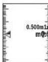
Con JAKTBK fakTop 6nireHReY3bHbIK Hewe peT KetirreHH Kepcetei. KacBn KepceKInep DcNneNe de Bnirey MaKcatbHa dA bHbKa Ketyi Kepcetei. Kb3bl KepcTeH HEmeCe Kb3bl TaKbipbH NaKbTI MAnHe KepeTei Her3rMmH dnCnnE cbiptbHa Tpyca.
KoBeydi onwey/CaHdbik ypoBeh
Ehcti enweydi/caHdbk deHreyni TaHaHbI3.
Onwey kypabbl eki Kyi apacbHda e3reptei.
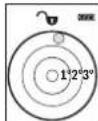
CaHbIKeHReHbICAHbIHrOpHOraHTaJIbHHeMeCeBepTnKaJIbI bafBHITanybHa Kb3MeTeIeMbICaJIbIKipKByfblMaHHa,CyblTkbl WkHeT.6). Erep 3^ ehiciapTbnKeTc, OHdaHcnneJeWapKb3blTcyTeKaHaJIbI
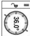
Kenbeyi enuwe Kepinicti Hemece eHcrti (Mbicnbl, catbl. TaHHuapblx, xHaasdpblkipictipyde, kybpnpabcianya T.6.) enuweyre k3mert etdi.
Kenbeyi enuwe yuiH eriri zkaibtck petihne enuwe KypablnbH coJxaBfo bonan. Enuwe aiciHde Kpcetkiw XbnbItaca enuwe KpaBn KaHbHa KeN KcaTbIHANbOanbl.
CaKayfynHKunnaIapbl
OpOpbIHDAHAn EJIeuyin MHI MeH COHfBI HETNKeCi ABToMaTtBcAcaTaIaDbI.
CaKaTaJaFaH MAn KepcTeKlWi
MaKcHmAnIb30MnHep(EnweyMaHepi HEmeccecoHbHAtnxenepe)waKbipy MymKIN.
CaTay fynKUHcBbH TaHaBb3.
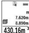
HcnnneHJxKofapfkafbHaCaTaNFAH MHeH HEmiP Kepctinei,
TeMeHnE NCTi CaTaNFAH MOn B6e ConDa THeTi CIneY OuWey FyHKnAcb.
CaTaNFAH MaHepei AnFa EK3y YUH 3 [+] nepHecin BacbH3.
CaTaNFAH MaHepei aptKa EK3y yUH 8 [-] nepHecin BacbH3.
XaTaMaH XoK BoNcA HcNne TMeHri XaFbHaD "0.000" an Kofapfba
XaFbHaD "0" Kepctinei.
EHcoHfblMmHJAAIa1OpbHnA TypaIb,anEcoHfbcbl30opbHda(30caKtaFAN MAnepi KOnXeTImDi BONFaHa).KeHHrMaHdi cakTaFAHJaKaTApaaapaaBIM eHecck MmHKOHBnAbI.
160992A48U|(18.12.17)BoschPowerTools


OBJ BUCH-2450-006.book Page 365 Monday, December 18, 2017 12:17 PM
Ka3aKaJua|365

CaKtaftbIuTafBblEwipy
KaMa3MybHJXOIOYiH7[Func]nepheciHTaHdAn caKAYHkUraCBH TaHaBb3.CocBih Kocy-eipy nepheciH5 [ ]KepeTInreH MaHdiXOIOYiH 6acbl3.
4 nepheimen Kocy-ewipy nepheci5 [6] 6ipde bacy apkblbapnbKxadn TpyraH MAnep JoBlnaBl.
Mændepj Kocy/any
Onuey MAnepi HeMece CoHfB HAtnKenepej Kocy HeMece any MyMknH.
MhandepdiKocy
TeMeHderiMbIcAJa aydaHdapDbKocy cHaTaTnFaH: AyaHdbi"AyaHdbIeNwey"6enimi 6bHua eceTeH3,3616etin KapaHb3.
3[+] nephecih 6acbHb3. EcenTeIReH aydah MeH “+”Benrici
+93.405 m 2 1
AayanbIy AyanbIy enIeye benIMI 60bnHIIa ecnTeH3, 361 beTH KapahBz. EkinuI enIey oepbnIaHan hCOn, ekniui ayad enweydi HHTKeci nncnien JteMeHJI KafBHaKe pceTineCi. CoHfB HHTKHei Kepcety uin2 [ ] enIey nepheci KaTia baccHbN3.
Eckptne:YbHbIbIKbIbnweyde COHbI HnKepey Kcpctinei.
Mankdepni any
MAnepdi any yuih 8[-] nepheci h bacihb3. Keinri apeketep "MaHepdi Kocy" anicihe ykac.
Onwey hataxeneepin xio
Kocy-eiipy nepheci 5 [ 心 ] kbiacka 6abbin 6apbikn 6euy dyHKunanapbHda coHbf ecenlenre Hmndepi KIO MyMKIN. Kocy-eiipy nepheci 5 [ 心 ] 6iphewe pet 6bacbnin eniye MAndepi kepi perrinikneHkoibnaIbI.
Onwey 6ipnirin anMaTbpy
Her3iri napametpiHne "m" (Metp) eIwey 6ipniri 6oana.
Owney KypanbIK KocbiHb3.
7 [Func] nephecin 6acbin yctan, "Heriari MAnep" Ma3ipIe etri3. "ft/m" Taandahb3.
3 [+] hemec8 8 [-] nephecin 6acbin, anwem bipinir aybctbpih3.
M3ip TaMaBfHaH uHy FuYuH 5 [ ] Kocy-epiPy nepHeci6 BacbHb. OIwey KpaBnEwipdyen coh TaHdAnrH npaMeTp caTaNab.
Bosch Power Tools 1609 92A 48U| (18.12.17)


OBJ BUCH-2450-006.book Page 366 Monday, December 18, 2017 12:17 PM


366
Ka3akua
Bluetooth® nHTepfchci
BaKa KypaIapFa DepeK TaBImaIay
Onuwey Kpyanbl BleetothMoyunime HkaabkTaNfH, on paHnoTeXnKaApKbIb
benrini MobnbIkbKaBnaybIkypanapFa BleetothyBbIbApKbIb
depeKtepdiTacmbaNayfMyMKiHdkBepee(MbcIcBcMaptfoh, pnaHuet.
Bluteoth6BaIaNbCbIyHtAN eTinETHkyenIK AnfBisapTAPtypaBIs Bosch
HHTEPHTCaBTHDa TEmeHderI MeKeHNaTaTabCb3:
www.bosch-pt.com
BacaMaIImeTepDi Bosch eHIM Be6caHbHa Ta6acbl3,QR KoobH KapaHb3,8GetInHe.
Bluetooth® apkblnbpekeptepi TacbImanayda Mo6nblbka6blnybkypanmeh 0niwey kypabnlapacbHda yakltbA kApbHdanybna da bOana. Ce6bi eki KypanbnBbip-6ipie KaBbKtBfBHa Hemece enwey hbcahHbda bonyb MyMKIN.
Moibblk ypanra Bluetooth yuibfblapkblbpekTepl TaBImaaydb6enceHety
Bluetooth® INTEPDECIN6BENCEHETYUHN ENUWey KypaANbIHn BLeTooth® TYMEcIN 6 bAcInbI3. Bluetooth® CmHanbIN BENCEHETY UHN BLeTooth® nepHeCIN 6 Hemece
3[+] nephecih 6acbHb3. MoBnblbky KypalbHbIa Bluteoth yuBbFbHbH 6encHei bonyih kamTamaib3 etH3.
M6nBdy KpaanbH fyHKunanapbH Keheny Xane depeKepdi Ehdeyi OHTaNaHbpyuH apHaB Bosch 6apnapamanaB (Apps) 6ap. OHkabnayb KpanaF6aHaNbctb Tict dyKeHepde catbn anyfa 6oana.
Bosch 64aapnanaanapbsh 6actaydaoh coM6nbI KpapanmEn enuey Kpbanb apacbHaabaihbc Jcakanaib. Biphebe6cneni Eunuy Kpbanb Ta6bnca,Kepeki enuey Kpbanb Cepnblk Hempi Heri3Hne TaanBa3.
BaIIaHbIC KyI MeH 6eNcHJI BaIIaHbC (a) eUwey KypaIbHbH KyI naHeniHde h KepceriNi.
Bluetooth® yawbirbiH eWipy
Bluetooth® 6aɪnəhɪbɪn 8ɪpɪy yɪn iBleɪoth® nɛpheciːn 6 bɑsɪhɪs. Bluetooth® Cɪrɪhʌbɪn 8ɪpɪy yɪn iBleɪoth® nɛpheciːn 6 Hemece 8 [−] nɛpheciːn kai t a 6acɪhɪs Hemece onlwey kypənɪbɪn 8ɪpɪpɪhɪz.
Paindanahy HycKaynapbi
Baca mImeTepi Bosch eHim Be6caaTbHa Ta6acb3, QR Koobn Kaapb3, 8 getHe.
Oniweky KypanbIpaNHO yHbIbImeHN Xa6dbkTaNFaH.Keprinlki naDanahy WeKteynepiH, MblcAoBIyWakTapda Hemece emXHaHApA, caKtay KepeK.
1609 92A 48U| (18.12.17) Bosch Power Tools


OBJ BUCH-2450-006.book Page 368 Monday, December 18, 2017 12:17 PM


368 | Ka3aKaIIa
KaWbIKTBkTb10peTenWeH3.
Keke enwemepin aybtkbyoptaaKaenemHmakcmandb ±4 MMacnyBepeK, TOnbik enwey optacbl konaIbkaFdaAeYi Kepe. Enweynepj Ka3bn, dandirih Tekepiia.
TaraHMeH naIaIaIaNy (kepeK-kaPaKaTap)
TaraHb icpece ykeK aBkTapbl enweye naIanaHy kep. Onwey KpaBH 1/4" bpaHdAmeH 13 TaraHbH 19 XbInam anMaCTbpy TaabHbHa HemeCe CTaHApTb foTO TaraHbHa opHaTBbI. Bekity bpaHacbmeH XbInam amMaCTbpy TaabHbH bekITi3.
TafaHMeH onuayneepin HcHer3ri Xa3bIKTBfBn 4 tyMecin Bacbin Ticti pete OphatbHb3 (Her3ri Xa3bIKTB6ypaHa).
Katenik xa6apbl
Erep enwey npbc opbHnmaTbH bocna, dncnnnepe "Error" katenik xabapkepcetinedi. Owney KypaunbH eupin KaTaN KocBn, enweydi KaTanaHb3.

Onwey Kpyanb ap6ip enweydiH yypbc opbHdaynb 6aBnaiDb. AkaynbAakbnHdAna, dncneJeT Ke kHIi Benr kepcetinin enwey Kpyanb eedi. Byj kaeJadpa Hnye Kpyanb HbIa catyBbHb3 apkblb Bosch kb3MetKepeTy optanfBbHa anapbHbI3.
TexHHKaIbIK Kytim XKHe Kbl3MeT
Kb3MeT Kcpcty KHe Ta3anay
Onwey KypaBH Ta3a YcTaHbI3.
Onwey KypaJIbH cyFa HEme6 6aKa CBybIKTbIKTapra 6aTbpMaHb3.
Jactahynapdbc yanaHan, JyMcaK u76peKePNen cypti3. Kyfbu 3aTAPbI Hemece epitkiutepdi naDanaanhabhi3.
Ka6bIyay HnH3acbH 14 Ke3iJipik HeMece foToaannapat HnH3acb KyTImHne Kytih3.
KeHey yuHnwey KypabH KOpFay KaNTacBHJa 16Ki6epiH3.
TybHybIka Kb3MeT KepcTey XeHne NaiDanahy Kehectepi
Kb3MET Kepcety Webepexahacbi HmDi JxHcyeJXaHe KYTy, coHdaiak KocanKb6bnuekTept Tpyalb cypaKaTApFy aayan bepei. KaKeTI cIb36aIap MeH KocanKb6bnuekeTp Tpyalb AknapatB Mya MEKeHKaHaih Ta6ab3:
www.bosch-pt.com
160992448U(18.12.17) Bosch Power Tools


OBJ BUCH-2450-006.book Page 369 Monday, Deccmber 18, 2017 12:17 PM


Ka3akua 369
Kehe6epyu Bosch Kb3MeTKepepi EHMi naiDanaHy XHe OlanDbH KocanKbl 6bnwekeptepyra panby cypaKaTpabHb3FaTHaHaKbI kayanbepei.
Cypakt KIOO KHe Kocankb6nuekTepe Tancbipc6epy Ke3iHne MInDteTIyPde HIMIN3ayBtBk TaKaiuacbHaDaftb10-caHbEHHemPiH Ka3bHb3.
EHdipywnanapbmeHOpmaIabnHbCakTaNbMeHneKtpKpaBnKHeNey
XaHeKeiNiDkbl3MeT KepcTe 6apNkMmNEKeTep aMyaBnHaTeK "PoepTe Boi
PhiMaNbIK Hemece ABTOpN3aUNHaFn K3MeT KepcTeOpTaNbKTapbHa
opBnAaJa.
ECKEPTY!3aHcb3KoHMeN aKeiHReH eHIMdepPi naJanaHany KayintI,
deHCaynbHbHb3Fa 3HH KeTIpyi MyMKIn. OHIMdepPi 3aHcb3XacayKaHe tapaty
aKIMuINIK XeHae KblMbICTbIK TeTin 6BoHHa 3aHMeN KyDanaHaDbI.
Ka3aKCTah
TybHyyBnapraKehe6epeyHeaFbMdpblKa6blnyOpTaIbFlb: "Poept Boi" (Robert Bosch) KUIC
AMATKI.
Do not stare into beam
Class 2 laser product
OBJ BUCH-2450-006.book Page 371 Monday, December 18, 2017 12:17 PM
Romàna 371
OBJ BUCH-2450-006.book Page 373 Monday, December 18, 2017 12:17 PM
Romana | 373
| Telemetre digital cu laser GLM 50 C | |
| Celule de accumulator | 2 x 1,2 V HR03 (AAA) |
| Reglare unitate de mãsurã | m, ft, in |
| Transmiterea datelor | |
| Bluetooth® Bluetooth® 4.0 | (Classic.si Low Energy) (g) |
| Banda freventelor de lucru | 2402 - 2480 MHz |
| Putere de emisie max. | 2,5 mW |
A) La masurarea de pe muchia antioarai a aparatulii de masura, pentru o capacitate ridicatade reflexie a tintei (de exemplu un perete vopsit in alb), lumina slaba de fundal si temperatura de lucru de 25^ . Supplementar, se poate lia in calut al abatere de ± 0.05mm / m .
B) La māsūrāra de pe muchia posteriora ā aparatului de māsūrā, pentru o capacitate ridicata de reflexia à tîntei (de exemplu un carton alb), lūnina uternica de fundal sī temperatura ambientá de -10°C pānă lā +45 °C. Supplementar, se poàte lua in calcol abatère de ± 0, 15 mm/m.
C) Dupa calibrarea de catre utilitator la 0^ s 90^ trebuie luata in considerare o eroare de inclinare supplementar de ± 0,01^ /grade panla la 45^ (max.).Drept plan de referinta pentru masicurarea inclinari serveste latura stangaa aparatului de masa.
D) la o temperatura de lucru de 25^
E) In functia de masurare continua temperatura maxima de fonctionare este de +40^ .
F) cu exceptia compartimentului de baterii
G) La aparatele cu Bluetooth® Low Energy (joasa energia), in functie de model si sistem de operare, est espositibnau se poata realiza associerea. Aparatele sa Bluetooth® ttrebuie s sustin a profilul SPP. H)Bluetooth® deactivat
OBJ BUCH-2450-006.book Page 376 Monday, December 18, 2017 12:17 PM


376 | Romaná
La deconectarea aparatului de masura, valorile memorate si reglajele efectuate ran man stocate in memoria acestua.
Procesul de māsurare
Dupa conectare, aparatul de masura se aflin functia de masurare a lungimilor. Pentru o alta functie de masurare, apasati tasta 7 [Func]. Selectati functia de masurare dorita cu tasta 3 [+ ] sau tasta 8 [-] (vezi , Functi de masurare", pagina 377). Activati functia de masurare cu tasta 7 [Func] sau cu tasta de masurare 2 [▲].
OBJ BUCH-2450-006.book Page 381 Monday, December 18, 2017 12:17 PM
Romana 381

Aparatul de masura masoara continuua dista ana la punctul de por nire. Sunt afisate lungimea definita cat si valoarea masurat a curenta. sagaata de ros respectiv cea de sus indicata dista cea mai mica panla marcajul urmator respectiv dista panla marcajul anterior.
Indicatie: La másurarea continua, prin apásareata tastei 4 puteji stabili si o valoare másurata ca fiind o lungime definita.
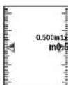
OBJ BUCH-2450-006.book Page 383 Monday, December 18, 2017 12:17 PM


Romana 383
Stergerea valorii masurate
Printr-o scurtapapasareatasteipornit-opr5 [ 0] puteti sterge,intoatefunctilede masmure,ultima valoare masuratadeterminata.Dacaseapaasacurt,demai multorei,tastaornit-opr5 [ 0] valorilemasuratevorfi starseinordine inversa.
Schimbarea unitati de masura
In setarea implicita, unitatae de masura este, m (metru).
OBJ BUCH-2450-006.book Page 384 Monday, December 18, 2017 12:17 PM


384 | Romaná
Service scule electric
Strada Horia Macelariu Nr. 30-34, sector 1
013937Bucuresti
Laser Radiation Do not stare into beam Class 2 laser product
AkoTeKcTbHa npEynpEnIeHnata Ta6eNkHe eHa Baunna Ean, npEn nycKahe Beknnoataa 3aIenete Bbpy Ta6eNkata BKnoueHn BOKmneKTOBkata CTKeK p TcKCT Ha Baunna e3NK.

He hacoubaIte na3epHnMbKbMxopaNkB0THN BHMmaBaIte da He norendhe Tne HncpecTeBHO Cpeu Na3epHnBtBuNN Cpeu HerOBO OtpaKeHne. TaKa MoKTe Da 3acnenTe Xopa, Da IpiHnHTe TpyOBn 3IOIOnyKn Hn Da IpeHnBkTae YbpeKaHe Ha OHne.
Ako na3epnHrIbH nonaHne B OHTe, H3aTBoPeTe Bb3MOxHO H-6bp30 n OTdpHHe TnaBata cHOT na3epHHb4.
He n3BpbWbaiTe h3MeHEnHa n0 na3epHToO o6OpyDbaHe.
H3no3BaTeOuNATAaHa6nOdaBaHe HaIa3epHnaIb4Kato npedn3pa6oTHNoUHa. Te3n OuaNa Cnykat 3a no-d6pTo Ha6nOdaBaHe Ha Ia3epHnaIb4,TE He npedna3Bar ot hero.
He H3no13BaIte Ounnata 3a Ha6nOdaBaHe Ha Ia3epHnIb4 KaTo CbHueBn Ounna Hnn Dokato YuaCTBaTE BynHOTo DBHXeHne. Ounnata 3a Ha6nOdaBaHe Ha Ia3epHnIb4 He OCHnPTBaT 3aHTaOT yUPTpaBnOteOBTe bNn OrpAHHaBat TbB3PnEMaHTo HA UCBEToBE.
DonyckaTe H3MepBATEHHTypeJa 6bJe peMoHTpAHcMoOTKBAHnHnHnHpaTHeNmCaOMCn3NON3BaHeHaOprrHAnHHpe3epBHNactn.CToBaCe rapaHTnpa sana3BaHTo HaФHyKuHTe,OCnrypRaUe63oNaCHocTtHaH3MepBATEHNNypeJ.
He octabTte Dea 6e3 npK HAD3Op da paaboTc N3MepBaTeHHy ype. Morat HeBONHO da 3acnneT dpyrX opa.
He pa60TeTe cH3MepBaTeHHypeB CpeDa cNoBHWeHa onaHcOteKcnno3HH, B KOrTo HMa NeCHo3AnaHMH TeuHOCTn, RaOBe Hn npaxOBe. B H3-MepBaTeHHypeD MoRaT Da Bb3HNKHAT NCKPH, KOHTo Da Bb3nnaMeHr npaxa Hnnpaphte.
160992448U(18.12.17) Bosch Power Tools


OBJ BUCH-2450-006.book Page 389 Monday, Decembr 18, 2017 12:17 PM


BbIraPckn | 389
BHHMaHHe! PnH non3BaHTo Ha n3MepBateHNn HnCTpymert C BLeotho e Bb3MOxHO CMUaBAHeto Ha pa60Tata Ha DpyTH yctPOHCTBa N cbopbXeHHa, camoTeH n MeuHnCKn anapath (HaNP. bpDneHN CTMyNATOpH, cnyXOBn anapatn). CbToAke He moXe Na ce N3KnIOH eEBHTanyHO BpeHO BnHNHe Bbpxy Xopa HXNBOTn. He h3No13BaIte ENEKTOHnCTpyMeHTa C BKNIOeH BTooth B 6nH3OCT Do MeuHnCKn anapatn, 6eHNHOCTAHn, XMHNCH BcpbXeHHa, B 30NH C NOBHNeHA ONaCHOCT O EKCNIO3H N B 6nH3OCTdo B3pBOONACH MATEPHAN. He h3No13BaIte ENEKTOHnCTpyMeHTa C BKNIOe HBeLtooth B camoTeH, N36RaBte npObNkHTenHATA p60Ta B HenocpeCTBeHa 6nH3OCT Do TAnOTO.
TbproBCKoto HAMHeMoBaHne Bluetooth*KAKTO h rpaDnHnTE h3o6paxeHHa (nora) ca 3ana3eHa Mapka n co6ctBeHoCT ha Bluetooth SIG, Inc. BcKaO non3BaHe na Ta3n 3ana3eHa Mapka n Ha rpaDnHnTE h3o6paxeHHa OT Robert Bosch Power Tools GmbH ce 3bprwba noD nIueH.
Onncahne Ha npodykta H Bb3MOxHocHTe My
Mon,OTBOpTe pa3bBaUaTc ce cTpaHua CfhyprHe Ha n3MePbAtenHHypeH, DOKATO YETe pbKOBOCTBOTO, OCTabeTe OTBOpHa.
IpeHa3NaYeHHe Na ypeHa
M3mepBaTeHnATypee npedHa3aHcH3a H3mepBaHe Ha pa3ctoHH,dbNkHH, BHCouHH,HaknoHH 3a H3ncnBaHa HnOuHn O6emn.
PeayntaHTe OT H3MePbaHTo MoTg Ta 6bDat PpeaJeHn C Bluetooth Ha pyrHuype
TexHHueckn daHHN
OBJ BUCH-2450-006.book Page 390 Monday, December 18, 2017 12:17 PM


390|Былгарский
| Дифоь пазерени уразд за Измервае на glm 50 c pa3ctoHHa | |
| Инданую Измервае на разстони и пьбелa | |
| Диаллэон на Измервае | 0°-360° (4x90°) |
| Измервае на Накнон | |
| Диаллэон на Измервае | 0°-360° (4x90°) |
| Точность на Измервае (объknовeto) | ±0,2^(c)/(d) |
| Минимално денины на скалата 0,1° | |
| Овши падаметри | |
| РавOTEN Tempepatурени палалз氧н | -10°C...+45°C |
| Temperatурени палалз氧н за сухпавае | -20°C...+70°C |
| Овочтелна влажноct на вьздуха, макс. | 90% |
| Клас пазер | 2 |
| Тил пазер | 635 nm, <1 mW |
| Диаметьг на пазерни льч (прн 25°C), пибл. - на разстся поюн 10 m | 9 mm(d) |
| - на разстся поюн 50 m | 45 mm(d) |
| АВТOMATУНО ИЗКЛЮВАЕ с Vide п�бл. - пазер | 20s |
| - Измерваленую (бez Измервае) | 5 min(H) |
| Маса съласно EPTA-Procedure 01:2014 | 0,10 kg |
| Габаротни пазмери | 106x45x24m |
| Вид зашита | IP 54 (заштон среши прахи ворDNи пьскN) |
| Бatepersn | 2x1,5VLR03(AA |
| Актулатоги бatepersn | 2x1,2VHR03(AAA) |
| Настояваце на мerte国安да сеница | m, ft, in |
| П repнагане на данни | |
| Bluetooth® | Bluetooth® 4.0 (нормален нсккоевэрпен реким) (a) |
| РавOTEN чебтөн палалз氧н | 2402 - 2480 MHz |
| Мамс. мошост на Изльчынe | 2,5 mW |
160992A48U|(18.12.17)BoschPowerTools


OBJ BUCH-2450-006.book Page 391 Monday, December 18, 2017 12:17 PM


BbIrapckn | 391
A) PnH3MepBaHa OE pIeHNHb Hb HA HcTpyMeHa 3a3MepBaHa 3a BHCoka Bt3MOxHOCTa Otpa3BaHa He ceta (Hanp.6oBmCana B6no CteHa) e Baxho Cnofo DOBOHOBOc BOETNHeH N 25 °C pa60THa TneMetpeyHa.OCBe HTO TnpBaDa a Ce OTNtO KTOHEnHe ± 0,05 MM/M.
B)ПинзмерраимеТДАг.ДИЗНБЯБСЕВЕМЕРБALEHINHурд.КOFATOOTPAPKATEENHTeCNOCHOCHTHa
NETAч BAICOKN(HANp.6BJKAPTOH)Ипсн работаTNEMPETYоT-10°Cdo+45°C.Tp8BaJa
CEOTHDAONHITENHOB3MOKHOKIOKTOKJOHENEHOTO±0,15mm/M.
C) Nge, noBpBeHTeKo KaHbOpAne npn 0" M 90" np6BaJa ce b6KnDaBaJOnsHHTenHa rpeuKa haNoBtHeNe HrO 0.01" /rpAdya Do 45" (MaKc.). KaTo ntpBaPaHa paBBHHa npn H3MePbaHeto HA NaHkIOI cyNk INBATA cTpaHa Ha3MePbaTeINHpyEpd.
D) npa 60TaTeMnepaTpya 25^
E)BpeKHM Ha HenpeKbchato H3MepBaHe MaKcHmAnHata pa6oHaTeMnepaType +40^
F)6e3He3JIoTo 3a6aTePm
G) IpnyyepnC HNCKOeHPnEN peKmHa BLoothtoa (LOW Energy) B aABNCMOCT OT moenaH one paunHHa CnHcMe a E bMkoHn Ha He Moeke da cE rpaanBp3ka. YpeDte, cKOHO CE Cbbp3-ate upe3 Bloothtoa" npb6ba da noPpTAPnp0fina SPP
H) Bluetooth® n3knquen
3a eHNO3HaHOTo HdEHTnHmnpaHe Ha Baunr H3MepeTeneH ypeD cIyKcn cepHHRT HOMep 11 Ha Tabenkata My.
H306pa3eHH enemeHTN
HomepnpaHTo Ha enemEnITE ce OTHACo H3O6paXeHNeto Ha N3MePbATEENHn ypeHa CTpaHnata CfHyprnte.
1Диспnev
2 ByToH 3a H3MePbaHe []
3 ByToH 3a Cb6nPaHe[+]
4 BytoH 360 np Ha otnpabHa paBHHa
5IpyckOB npkeBcBaU[
6 Bytoh Bluetooth®
7ФyHKUHOHAEN6yTOH[Func]
8 ByToH 3a n3BaKdAne[-]
9 Kanak Ha rhe3doTo 3a 6aTepeHH
10 BytoH 3a 3actonopbaHe Ha KaIapaHa rHe3doTo 3a6atePHN
1.1 Cephen Hoomep
1.2IpeDynpednTeHaTabenKa3aNa3epHnMaB
3 Pe360Bn OTBop 1/4"3aCTaTMB
4 PnHemaaJneua
1.5 OTBOP 3a na3epnHn bqu
Bosch Power Tools 1609 92A 48U| (18.12.17)

H3o6pa3eHH enemeHTN

OBJ BUCH-2450-006.book Page 392 Monday, December 18, 2017 12:17 PM


392|BbIrapckn
16 PpeDn3HaaHTa
17 Na3epHa MepeHnHa nnoa*
18 Ounna 3a Ha6nlaDaBaHe Ha na3epHnHa
19 CtaTHB
pa3aHHTe Ha fhyprnte Hn OHncaHH BpKOBoCTBOTo 3a EKnnoTauny DonbHNTen
MCNOC6JIeHH He Ca BKNIOueHH B OKOMNIeKTOBkata.
Toka3BaHH eneMeHTH (n36Op)
a CbctoHnHa Bluetooth

Bluetooth®akTnBnpaH, HMaMaI3rpaDeHa Bp3Ka

Bluetooth® aKTHBpuH, n3rpaHa Hb3ka
b OtnpabHa paBHHa 3a H3MepeBaHeto
C INHdkatop 3a 6atepeyra
D PeIOBe 3a H3MepeHnTe CToHOCTH
e Pedi a pezynlata
PekmHa pabota
gPone3a bbrHa HAKIOHa
H CtaTycha neHTA
IChOBnHaCTpoKn
MOnTnpaHe
TocTabaHe/cmHaHa 6atePnHtE
3a pa60ta c H3mepeBATEHnH ype ce npenopb4Ba H3non3BaHeto Ha ankaHo-MaHraHOB6atePHNnHa akymnatOPHN6atePHN.
CaKymnataopHHbATEPHNCHANPEJHHe1,2VEB3MOxHO6poTHaH3MePBAHHTa Da eNo-MaIbK CpaBHeHHe c 6aTePHN CHANPEJHHe1,5V.
3a OTbapnHHe HA KANaka HA rHrEzDTo 3a 6BATEPHN 9PbPO HATNCHEt 6yTOHa 10 nCneI TOBA OTBOPeTe kAnaka. NcTabe TbeOshKOBHeHH INH AkyMynATOpHN 6BATEPHN. PnH ToBA BHMaBaTe 3a npabHnHata NoJIPOCT Ha 6BATEPHTE, NOKAaHa HA NIO6paxKeHneO t BtpeHnHATA cTPhA Ha rHrEzDTo 3a 6BATEPHN.
CneKato CHMBoBt 3a np3ha 6atepna ce noHBn 3a npbNbHa dnCnnner, ca B3- MOKHNO Oue npbN. 100 N3MEpbAHHH. Korato CHMBoBt 3a np3ha 6atepna 3anoHe da MHRc CpePBHe cBeTnHHe, He Morat da 6bDat H3BbPwBAHNOBeue H3MEpbAHHH. 3aMehete 6atepNHte, pecn. akymylatopNHte 6atepNHte.
160992448U(18.12.17) Bosch Power Tools


OBJ BUCH-2450-006.book Page 393 Monday, Decembr 18, 2017 12:17 PM


BbIrapckn | 393
BnHn CmHnBe BCHN6 BatePHn, pecn. akymnatOpHnTe 6atePHn eHOBpEMeHHo. HnO3BaHc moTa 6atePHn HnAkymnatOPHn 6atePHn Ha eHN PPOINsBOHTEN n c eHnKbKanaTET.
Korato Hma Da H3non3BaTe H3MepBaTeHHH ypeD npOdbNkHTenHO BpeMe, 3aBxJaTte 6atepHnTe, pecn. akymyatopHne 6atepHn. Pnp npOdbNkHTenHO cbXpaHnBe H ypeDa 6atepHnTe H akymyatopHne 6atepHn MoRt da KopoDnpat H da ce Camop3aPeHnT.
Pa60a cypepa
Iyckane Bekcnoataa
He octabTeypeBaBKnOuHcE3Ha3Op;CnEDKATOpNpKNIOHTepaOta, ro H3KnOuBaIte.DpyrHmuaMOratda6bDatacneneHOntna3epHnA bU.
IpeNa3BaIte N3MePbATEHnHn np6Op ot OBnAHHBaHe H dPeKTHo nonaDaHe Ha cNbHcEeN bH.
He 3naraHte H3mepBaTeHHy ypeHa ekCtpeHHN TemmpaTpHy nHnpe3Kn TemnepaTyH npOemn. Hnp He 0ctabHne IpOdbJHKteHNO BpeMe B ABOMoHn. Pnp rOeMH TemnepaTyH pao3Nkn OCTabHne H3meBpaTHeHytpeJa ce TEmnepHa, npDeHa da RoBkIOuHTe. Pnp EKCTpeHH NtempeAtpHy nHn rOeMH TemnepaTyH pao3Nkn ToOHcCTHa Ha 3meBpaTHeHHy ypeM oKeMa Da Ce BLOHn.
36RBAHTe CnHHYyapn BbpyxN3MepBaTeHNHyypeid.Cnei CnHHBbHmHEaxAHHHBzDECTBTRP86aDa H3BbPwIte NpOBepKa Ha TOUHOCTA Ha N3-MepBaTeHNHyypeid.NpEHa npOblXKeIa Ro H3NONBate (BHXeT, PpOBepKa HA TOUHOCTA Ha N3MepBaHae BdJNkHcY, cPraHn403).
BkIIOUBAHn H3KIOUBAH
-3a BKNIOUBAHe Ha H3MEpBaTeINHnYpeI HnHaIa3epa HATNCHete KpaTkoTpaH06yToHa 3a H3MEpBaHe 2 [▲].
3aBKnIOuBaHaeHa3MepBaTeHNnYpeD6e3NaepaHaTHcHeteKpaTkoTpHaHO NyCKOBHnPpeKbCBAu5 [
He haooyaIte na3epHHNbKbM Xopa HINXHBOTHn; He IneaIte cpeuy na3epHHNb4,cbIOHO TOrJMOpa3cTOnHHe.
3aHAKIOUbaHe Ha HsMepBaTeHNHrypeiHaTnCHte H3aIpbXTe NycOBn npekbcBau5[ ]
PnH N3KIOUbaHe Ha N3MEpBaTeHHypeD HAMnpaIte Ce B NaMeTTA CTOHOCTHN HAcTPOKITE Ce 3ana3BaT.
Bosch Power Tools 1609 92A 48U| (18.12.17)


OBJ BUCH-2450-006.book Page 394 Monday, December 18, 2017 12:17 PM


394|Былгарский
№MepBaHe
CneB KKnUoyBaHe N3MepBaTeHNHRTyepe Ce HAMnPa B pexHM 3a H3MepBaHa He nblNHNH. 3a Dpyra fynKuHa H a N3MepBaHa HnatChete 6bToHa 7 [Func]. N3ePeTe JekAnHaTae FynKuHa 3a H3MepBaHa c 6bToHa 3 [+] HnH blyToHa 8 [-] (BHXte, PexHMn Ha N3MepBaHa), cTpaHnHa 395). AKTbBNpaTeyHKnHrtA 3a H3MepBaHa c 6bToHa
7 [Func] mnc 6byToHa3a n3MepBaHe 2 [▲].
CnE BKNIOUbaHe 3a OTnpaBHa paBHHa npH N3MepBaHHaTe ce yCTaHOBBa 3aHN Hpb Ha N3MEpBaTeHHa ypeI. 3a CmHa HA OTnpaBHa paBHHa BHKTe, N36Op Ha OT npBHa paBHHa", cTpaHHa 394.
Dionpete N3MepBateHnry ypeIdo XeHaHata HauHaToKa 3a N3MepBaHeto (HaNP. cTeHa).
YmTBaHe:Ako H3MepBaTeHNHHTypeE 6HN BKNIOUe C NcYCKOBn PnKbCBau 5 [ ] , HATHCHE Te KpAikToPaiHo ByTOHa 3a H3MepBaHe 2 [ ] , 3a Da BKNIOUHTe naepa.
3a CTAPtnpahe Ha n3MepBaHe HATNCHE KpaTkoTpaHIO 6yToHa 3a n3MepBaHe
2 [▲]. Cnep Toba nasepHnT MbY ce BkNIOyBa. 3a CneBauo n3MePBAhe noBtoper Ta3n npOeDpya.
He haoBaHte na3epHHaMbKbM Xopa HnN XHBOTn; He rnaTe cpeuy na3epHHaB,cbso HO tOrMa p3cToHHe.
YmbTBAe: N3MepeHATA CTOHOCTO6NKHOBEO Ce NOBRA CNE0 0,5nHE NO-KbCHOOT.4. IpOdbNJIHKTeIHHOCCTA 3aBHCN OT PA3cTOHNHeTO,CBEITNIHHNE CToTHOWEHHNOTpAXaTEHNHTCBOHCTBA HA CEJIeBATA NOBbpxHOCT.CNE pRKnIOUVAbe HA N3MEpBAHETO Na3epHNR TbC eN K3JIHOBA ABTOMATNUHO.
H36op Ha otnpaBHa paBHHHa (BHXTe fHr. A)
3aH3MepBaHrTo MoKeTe Da H36nPaTe MeKdy TpHa pa3nHHaHaAHHHpaBHHH:
-3aHnpaBbHaN3MepBaTeHHypeD(HaPp. npn DOnnpaHe do cTeHa),
- npednna p6 ha n3mepbaTeHHypei (HaNP. npn H3mepBaHe oT p6ba Ha Maca),
- cHTbpbT Ha pe3bata 13 (Haip. 3a H3MePbaHe O TcTaHB).
3aH36opHaHaauhAnataToKaHaTCHETe 6yToHa4.C6yToHa3[+]mN6yToHa8[-],mN6ByToHa4n36peTeKeNaHATAHaauHAnToKa.BHHa nCneBkNoBaHe3aHaauHAnHa ToKaCe H36bPa3aHnHtPb6Ha N3MepBaTeHNHypeN
MeHNO,OCHOBNHaCTPOINKn
3a Da Bne3eTe B MeHOTo ,OCHOBn HAcTPOKn"(i), 3aDpBxTe 6yToHa 7 [Func].
H36epete cboTBeTHaOnUHnCTOHOCHTaN.
3a da n3ne3eTe OT MeHOTo OCHOBHN HAcTPOKn" ,HaTHcHete 6yTOHa 3a BKNIOUBAHe N3KNIOVABe 5 [°].
160992448U(18.12.17) Bosch Power Tools


OBJ BUCH-2450-006.book Page 395 Monday, Dcccmber 18, 2017 12:17 PM


BbIrapckn | 395
OcbetneHHe Ha dncnne
OcbetneHneto ha nncnner e BknioueHo. C orne nppeNaBaHe Ha 6atepnt/akmyIaTOpHnTe 6atepn, aoB npDblKeHHe H npBn. 20 cekyHn He 6bHe HaTHcHATbyToH, ocBETneHneto Ha nncnner ce NkNouBa.
PexmmHaH3MepBaHe
№MepBaHe Ha bNnHa
H36epete H3MePbAe HaIbIKNHa I
3a BKNIOVAHe Ha Ns3epHnNbHATNCHETe KpATKOTpaHHO 6yToHa 3a H3MePBAHe 2[▲]
3aH3MepBaHe HaTCHETe KpaTKoTPaHNo 6yToHa 3a H3MepBaHe 2 [▲].H3MepeHaTaCTOHOCCTe H3O6pa3RaB B DOnHATA CACT HaDnCnEe.
IIOBAPRIIEPOHPHTCtBNKPNBCKNOeBAIOH3MEPBAHE.106EHOH3MEPENA CTOHNCTO HAMNPAHADONYHADNCNNER,NE
10.160m 11.430m
HnpeKbchato N3MepBaHe
PnHEnpeKbChato H3MepBaHe H3MepBateHNHTypeMoKeJa b6Je NpEmecBaH cnPMAO CEneBata TOka, Kato H3MepeHata CTOnHOCT Ce AkyaIImHa BcEKN0,5s. HanPmep MoKeTe Ha ce OJDAeYHrEOTcHeHa JKeNaHOTo pa3ToHNe, TeKyUTo paoCTOHNHe Ce BHXda HEnpeKbChato.
H36epete HenpeKbchato 3MepBaHe
3a BkIIOUBaHe Ha Ia3epHnIbUHaTNCHe KpaTKoTpainHO 6yToHa 3a H3MePbaHe
2[
Hacouete H3mepBaTeHNnYpei,doKaTo Ha nucnneCe H3o6pa3n CtoHocTaHa JeNaHaTa DblnNHa.
C KpaTOKpmaHo HATNCKaHE Ha 6yToHa 3a 3nMepBaHe 2 [ ] cnpate HENpeKbCHATOT0 N3MEPABeH. TekyIoo H3MePehaTc TOnHOCT Ce I3O-6pa3Ba DOyHa HAcnPner. MakChMaHATA H MmHmHaHa N3MepeHH CTOnHOCT Ca HAD HeH. HOBO HATNCKaHE Ha 6yToHa 3a 3nMepBaHe 2 [ ]ctaptna HEnpeKbCHATOTo H3 MePBAHe OTHauNo.
HenpeKbchatoN3MepBaHe ce N3KIOUOyBa aBToMaTHuO cIeD 5 min.
Bosch Power Tools 1609 92A 48U| (18.12.17)


OBJ BUCH-2450-006.book Page 396 Monday, December 18, 2017 12:17 PM


396 |Былгарский
H3mePbaHe Ha nioou
H36epete H3mepeBahe Ha nnoi
CneTObaH3MepeteNocIeNoBATEHNO HINPOHINHATAHbIXHHATA,KAKTOceH3MepBat bIXHH. Mexdy Bete H3MepBaHHa N3ePHHTbHcHe cH3KIOUBA. OTeCkata, KOrTo Tp8BaDa b6Be H3MepeHa, MnHa Ha CmBbOa 3a H3MepBaHe Ha IIOU
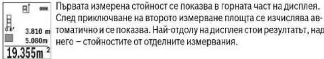
№3mepBaHe Ha 06eM
H36epTe H3MePbaHe Ha oBem
CnEITOBA H3MEpeTe NocNEoBATENoIHIPOUHATA, DbIKHHATA HINCOHNHTA, KAKTO CE H3MEpBATdNkHHM. MeKdy TpTne H3MEpBaHH Na3epHHrTbHc He cH3KIOuYBa. OeCKaTKA, KOTo TpRbBa Da bJde H3MepeHa, MHa Ha CNMBOna 3a H3MEpBaHe Ha o6em
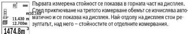
HnHpeKTHo H3MePbAe Ha DblxHHa
PaanolaraTe CTPn FyHKUH3a HHHNpeKTHO K3MepBaHe Ha pa3ctoHHe, KOHTo MoTat da6bDat npnaarAH Bpa3nHn CNtyaun.
HINHPeKTHOTo H3MepBaHe Ha IbIiHKHa CnyJH 3a H3MepBaHe Ha pa3CTOHH, KOHTO HE MOrAT Da 6bDat H3MEpeHH HeNOpCEpCTBeHO, Tb KATO NtBHa HbJa Hma ppenrTCTBHe Nt B KaTO B KpaHATA TOcKa HA mTaP3BaUaNoBbPxHOCT. To3n MeToD Ha H3MepBaHe MOKe DA b6Je PnHIOKeH CaMO BB BepTNKaHHO HapBaJIHe. BcKO OKIOHHe B xOpH3OHTANHO HApBaJIeHHe BOd nO yBENuAbaHe Ha rpeuKaT B H3-MepBaHTo.
YnBbAe: HnHnpeKTHoN3MepBaHa Ha pa3cTOnHH e BnHArI No-HeTOHO DTnpeKTHO. CbflaCHO pinnuHa ha paba TpekHTe pni N3mepBAHTo MOrat Ja ca nO-TonEMOTe3n npn DnepKTHoN3MepBaHa. 3aNoOp6pBaHa Ha TOUHOCTTa Ha N3MepBaHa npopNp4BaMe N03BaHTo HA CTATMb (He e BKIOueH BOKMIKeKOBkata). MeXyOTdINHtE N3MepBaHHa N3apePHIT IbOCTaba BKNHOe.
160992448U(18.12.17) Bosch Power Tools


OBJ BUCH-2450-006.book Page 397 Monday, December 18, 2017 12:17 PM


BbIraPckn 397
a) INHnpeKTHo N3MepBaHe Na HBCOuHa (BNXTe pHyp a B)
36epete HnHnpeKTHo HmMepBaHe Ha BncoHHa
BHIMABATIE N3MEPBATEHINHTI ype,da e ha ena Hc bca BnCOUHCA cDOnIHATA TOHKA HA N3MEPABE.CNE ToBA 3aBpTe T3MEPBATEHINHA ypeOKOHO HauHATA TOUKA 1^ (NIO6oPbAEHa HAcNlner Kato YepBeHa NHHIA).
CnepnnKIOUOBAHe Ha3MEpBaHTo pe3yIITaTb3 a TbpcHOTo pa3- 45.0° CTOnHHTeo,1" HbTaNa,ca HApeoEe HApoeHne cTOHOCHTa pa3
b)Довин Идпөртхо Имөрbaе Ha Bнсоунha (BnxTeФг.С)
H3MepBaTeHNHrT ypeD MOKeJa H3MepBa HnHInpeKTHO BcKaKbN pa3CToHHN, KOMTO Ca BB BEpTKaJIHATA paBHHHa Ha H3MepBaTeHNHrYpeD.
H36epete DBOHO HINDPEKTHO H3MepBaHa H BnCOnHa
H3MepeteOTceKHTe,1" H,2" B Ta3N NOcNEOBAteINHOCT,KaKTO O6HKHOBEHO H3MepBATE DJIJKHH.
CnepnKIOUOBAHe Ha N3MEpBaHTope3yIaTbT3a TbPceHATAOTcEeKa X"Ce N3OBpa3RA HA peDa e. N3MEpeHNTE CTOHOCTH 3a OTcEKNITE m128 450° m10454 ,2"N bTbna, a" ce N3OBpa3RaBt ha peBOBeTe d. BHIMABAte pRn BCuHKn EINHHu H3MEpBAHnHa HINHPeKTHO tpeJIaHE Ha BICOUHnA OTpNAHbTA paBHnHa (Hapr.3aHnrPb6 Ha N3MEpBATeHNH ype) da OCTBa HENpOMeHHe.
c) NmnpkeTHo N3mepBaHe Na dbIaKHa (BnXte pHr.D)
H36peTe HnHneKTHo H3MePbAe Ha NbJnxHa
BHMABAHTe H3MEPBATEHNHtYPedaHaHaCbTaTBAcOuHnHa, HA KOToE TbpcEHATA KpaHa TOnKa Ha H3MePBaHHeTo.CnEd ToBa 3aBbPerte H3MEPBATENHyped CnpMaO OITPiBbHata PabHHHa H3MEPepTeOTcEeKaTAt,1"KAKTOe H3MEpBaDbJIHnHa.
Cnep npKIOUbaHe Ha 3MEpBaHTo pe3yIaTbT 3a TbpeHOTo pa3- cTOnHHe, X" ce H3NcBa Ha peHa e. H3MepeHHTe cTOnHOCTn 3a pa3- cTOnHHeTO,1" HbTa, a" Ca H3NcAHn Ha peBOBeTe d. 10.000m
Bosch Power Tools 1609 92A 48U| (18.12.17)


OBJ BUCH-2450-006.book Page 398 Monday, December 18, 2017 12:17 PM


398|BbIgapckn
OnpeenHe Ha nnoa Hn CTeHn (BnXte pHr. E)
H3mepBaHrto Ha nlou Ha cTeHN CnyKHa onpeJenHe Ha o6ua nloU, cyMa OT HnKoIKO OTeHNO H3mepeHn PooN, HmaUu O6ua BnCOUHa.
Ha 3o6pa3eHnHa fHyrpya npmep Tp8bda a6bde onpeDeneHa o6uata nou HAKOKN KTeHN, KOTo HMaT eHn H Cbua BnCOUHHa HO pa3NJHn DnJXHHN L.
H36epete H3MEpBaHe Ha NIOuTa Ha CTeHN
H3Mepete BnCOOHATA H, KaKTo npn HopMaHO H3MepBaHa JaBnKHa. H3MepeHa TcOHHCTe NOKa3Ba Ha ROpHnpeC peyntAHTe. Na3epbT oCTaBA KNIQUEH.
CnE TOBA H3Mepete DbKNHATA LHa mbpaTcTeHa. NIOUta ce H3- cnNBA ABTOMATNo Hc NOK3Ba Hpe Da 3a peynta e. NocneHaTa H3MePAe HbNkHnOctBaHa DonHnPeD cpeytnAtOT H3MEpBaHe d. Na3epBtOCTABAT BKNUOH.
3.336m² CnEDTOBAH3MepeteIbJINHHATAL2HABTOPATACTHa.NOKa3BAAHTAHa peda dctOHcTOTN3MEpBaHEToCeCymnpaCdbJINHHATAL.CymataHa
DBeTeBnKHHN (POKA3BaHn HA cpeHNH PAE 3a pe3yIATn d) ce yMHOkABa Cb 3anaMetehata BcOuHn H. Obuata cToHocT ha nNoHT ca nKa3Ba Ha peda 3a pe3yIYTA tHe.
MoXeTe Da H3MePbAte Oue HeorpaHueH 6pO JbIaHHnLx, KOHTo aBToMaTHuHO ce CymHpTuMHOKabAT C BnCOUHNHaH.
PnpnOCTabKa 3a npBAnHnTO OnpEJIeHHe Ha IIOUta.e IbPbata HmMepeHa,bIKNHa (BHCOnHnHa ha NOMeUeHHeTO B TeKuYnprnPmep H) da e EHNkBA 3a BCNUKn H3-MepBAHnCTEHn.
IpehaheHaabJHHa(BHKeFmR.F)
PnTa3n FyHKnHcpeK3aBmHOrOkpaTHo npEeBaPnTeHNo 3aJaHeHa DbNKnHs (OTcEHa). Ta3n DblNKHa MoKe Da BSe pneHacNa HA dpyra NOBpXHOCT, HAp. c cen OTRPABaHE Ha DetaiHc E nHa Ncbla DblNknHa HnN 3a NoTROBka Ha NaHenn PnH cyxo CToPnteCTBO. MInHHMaHATA DblNknHa, KoTO MoKe Da bSe hAcTpoHa, 0,1 m aMakCNMAHHTA -50 m.
YbTBaHe:Bb yHKUra3a 3KapBaHe c NOKa3Ba pa3cTOnHHeTo 3a MapKupaHe HnCnner.PepepeuHTA He e p6ba Ha n3MePbATEHHHnCTpymEnT.
I36epete Ipehaene Ha dbnKinaHa
HactpoTe JKeNaHaTbNkHa.3a centa C6yToHa 7 [Func] H36epete cBtBeTHata UΦpa/No3uHn I pOmeHeTe CToHocCTTa Hc6yToHa 3 [+] HmH6yToHa 8 [-].
CTapnpaTe pHyKUHTA 3a npHeacHe HaNbIKNHa C6yToHa 3a H3MePbaHe2 [ ] n 5abHO ce OtdaneyeTe OT HAaHnHa ToKa.
160992448U(18.12.17) Bosch Power Tools


OBJ BUCH-2450-006.book Page 399 Monday, Deccmber 18, 2017 12:17 PM


BbIrapckn | 399
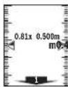
N3MepBaTeHnHrTpyed H3MepBa HenpeKbChato pa3cToHHeTO daHaJahnata ToUka. PnTo TOBa c NOKa3BaT eHOBpEmHo 3aJaDeHATA bIbKnHa n TeKyuata DblnKHa. DOnHata, pecn. rOpHata cTpElna NOKa3BaT hA-HaMKoTo pa3cToHHe Do cneDaAata, pecn. npExOdHata MapKnPobKn.
YnTBaHc:PiH HnpeKbChato N3MePbaHe MoKeTe Ja 3aJaTe TekyIaTcTOHOCT KaTo IeBaHa Upe3 HaNTCKaHe Ha ByToHa 4.
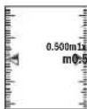
IIBATA CTOHOCT NOKA3BA KOI KIO TBN 3aJaE HATA bNIXHn E BnlaDocT TnHATA. 3eNeHtte CTePkn OTcPaHHa NdCnIIe NOKA3BaT DoCTHaHeo HbDnKnCA c cien MapKnape.
YepBHeHTe CTpeKN,peCn. YepBHeHHT HADINC NOKa3BaT peAInHata CTOHOCT, aKO pepepeHTHATA CTHOCT e H3BbN DcNIIe.
H3mepbaHe Ha haknoh/UnΦpOB HnBeHHp
136epete H3meBaHe HaKaIOH/UnΦpOba IIN6eNa
I3MepBaTeHNHnT ypeIe pIeBKnIOyBa AITOMaTHNO MeKny DBe CbCTOHHN.
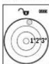
LHpObata Hn6eNa ChyKHa 3a npObePKa Hx OPH30HTAIHOTo HIN BepTmKnHO npPabHBaHe Ha oEKT (Hanp. MInHa MaHHa, XnAinHnKn T.H.).
Korato HakoHbT HaXBpH 3°, Ha DnCnIe CBeTBa YepBeHaTa ToKa.
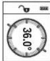
N3mpebaHTo Hn HauIOH CNYK 3a H3mpeBaHa hbrHn HauHOHeH NOBbpxHOCTn HnMCHENPnABn (Hanp. Ha CTbn6n, npanetn, CBODOBE 3a Me6eHN, npr npkepaHae NaTb6n nDp..).
Kato OTnpaBA HpaBBHnA npn H3MepBaHTo HA HAKNo CnyKnIbTa cTpaHa H3MepBaTeHNH ypeD. Ako no Bpeme Ha H3MepBaHTo zano-He da MIRa CBETNIHHNHT NIKKaTOp, H3MepBaTeHNH rypeE hAKIO He TbPdne CNHO NaCTPAHn
3anametbaheHaH3MepeHHCTOHOCTH
CTOHOCHTa,pecn. KpaHnHrT pe3yNTaT O BcAko npHKNIOHNIO N3MEpBaHe ABTOMaHHO ce 3anHCBA.
3anaMeTeHN cToHOCTH
Morat da 6bdat N3BHKBaHn Hn-MHO 30 cTOnHOCTn (N3MepeHH CToHOCTn HnKpAHn peyITATn).
U36peTeФyHKUHTa3anaMetBaHe
Bosch Power Tools 1609 92A 48U| (18.12.17)


OBJ BUCH-2450-006.book Page 400 Monday, Dcccmber 18, 2017 12:17 PM


400|BbIrapckn
BropHataaactHaIcnIepeKoKa3BaHomebpHTa3anameTeHata cToHcCT,OTOny-camataCTOHOCT,aOTnBO-ФyHKuHATA,pNkKTOe 6010npeDeneHa. HATINCHETebytoHa3[+],3aDaCepnpDBrXHHTe HAnpeB3anameTeHHe CTOnHOCTn.
HaTCHETe 6yToHA8[-],3a Da CE pNDbBnKHTe Ha3aD B 3aIaMeTeHHTe CToHOCt. Ako B nAMETTA HMA 3aIHCaHCT CToHOCCT, B DOIHATA YACT HA DnCnner CE H3o6pa3Ba0.000",a B rohpata -0".
Hai CTapata 3aAMETENA CTOHTOC CE HAMHPA B NO3HUNI B NAMETRA, HAIHOBAIATB HIOHNI 30 (Pn30 HANHINK KNTK NT NaMETTA). Pn3aNNHCBAHE CneDBAUHNCTOHTCHCNEI3TIPNA BHARN HAI-CTAPATA 3aANMETENA CTOHTOC.
H3tpnBaHe Ha cbIbpxKaHMeTo Ha nMaMeTTa
3aH3TpBnBaHe Ha CbDpKaHHeTo Ha NaMeTTa HaTHcHete 6yToHa 7 [Func] H36peTe
FHyKHN3aNaMeTBAHe CnTe T0Ba HAHTCHete KpATKOTpaHIO 6yToHa 3a BKNIOU
BaHe H3KIOUBaHE5 [°],3a Da H3TpHete cTOHOCTTa HA DCNPIE.
4ue3 eHNOBPeMHeHO tAHNCaHe Ha 6yToHa 4 N Ha 6yToHa 3a BKNIOUBAHe H3KIOU
BaHe 5 [°] Ce H3TpBtB BCMK3aNCAHn B NaMeTTa cTOHOCTn.
Cb6HpaHe/H3BaXJaHe Ha cToHocTH
H3MepeHH HIN H3HCNEHN CTIOHOCTM MoA Tda 6bDat cbHpaaHm H3BaJdaHn.
Cb6hpaHe Ha cToHocTH
CnEHNr npHMeP onncBa c6bnapHe rHa nIOuH: OnpeIeTe nOuTa, kAKTo e OINcAHO B pa3dEn „N3MepBaHe Ha nIOU", BHXTe CTpaHua 396.
HATHCHE6yToHa3[+].HaDCnIeCe noka3BAtnHcIeHata IIOU HmBOJbT,+."
HATHCHE6yToHa 3a H3MEpBAHe 2 [▲],3a da 3aoHete CneBaio 3M3MEpBAHe Ha IIOU. OnpeIeTe IIOUta, KaKTo e OINCAHO BpaDien "N3MEpBAHe HA IIOU. BIXTE cTpaHua 396. KOrato npNKIOuN BTOPO To H3MEpBAHe, peYITbT OT hrOe Ce NOKA3BA DOny HaHcNIIe.3a
da NOkAKTe pe3yNTATA, HATHCHE6OTHOBO 6yToHa 3a H3MEpBAHe 2 [▲].
YnbTbAe: PnN NmEpeBaHe Ha DblJInHa BeDHa ce noka3Ba pe3yntTaBt.
H3baxdahe hctoHocTH
3aH3BaKaDaHe Ha cToHocn HATNCHE 6yToHa8[-].No-HataBk ce npoepnpa aHaIorNHO Ha, Cb6bpa He cToHocn
160992448U(18.12.17) Bosch Power Tools


OBJ BUCH-2450-006.book Page 401 Monday, December 18, 2017 12:17 PM


BbIrapckn | 401
N3tpnBaHe Ha N3MepeHn CTOnHoCTn
PnBcNkHyHKU3aN3MEpBaHeMOKTeJaN3TpHneTOncENoN3MepeHaT A CToHOCT 4pe3 KpaTKOpTaHNO HATNCKaHE NaYCKOBINpeKbCBaY5 [ ] HeKoNkoKpaTHOTO HATNCKaHE NaYCKOBINpeKbCBaY5 [ ] BOHNIO N3TpHbAHE Ha N3MepeHNTe CTOnHOCTB O6paTHa NocEIOBATEHNOCT.
CmHaHa MePHaTa eHnHua
OCHOBHATA mepha eHHnuae m" (MeTp).
Bknoute H3mepBaTeHnHa ypeI.
3aDpBkTe HATmCHAT 6yToHa 7 [Func], 3a Da Bne3eTe B MeHIOTo ,OCHOHN HAcTPOKn .M6epete ,ft/m
HaTncheTe 6yToHa 3 [+] HnH 6yToHa 8 [-], 3a Da CMeHHe MePa eHNHua.
3a n3n3ahe O Ta3n OIuHn HATnCHete 6yToHa 3a BKNIOUBA He N3KIOUBAe 5 [ ]N3bpaHATA MePA eHNHua Ce 3aNa3Ba H CneH N3KnIOUBAHe Ha N3MePbTeINHrypeD.
Bluetooth®-нтерфец
PepHoc Ha daHN KbM npyH ypeH
M3mepBaTeHnTpye e cbopxeh C Bleetoth Moyn, KOIO No3BOBA 6e3KuHep npeHc Ha daHH KbM onpeJeHn MOBnHn yCTPOIcBA C Bleetoth HHTeppeic (Hanp. cMaprfoHN, Tabnet).
DOnnHHTeHa HhFOpMaIg OTHOCHO He6bXoIMMHe npEIOCTABK3a HrpaXdAe Ha ycneuHa Bluetooth MokeTe da HamePte Ha HHTepHET cpaHuaTa Ha BoHa apec
www.bosch-pt.com
No-noDpo6HaHnHOpMaun MoKeTe DaHaMepeTe Ha npOyKToBaTa CtpaHua ha B0w, BxKTe QR-KoDa Ha CtpaHua 8.
Pn npheoca Ha daHHN C nOMOHTa Ha Btloeoth e Bb3MOXHO Bb3HKnBaHTo Ha 3a- 6abHHe MeJy Mo6HnHOTo yCTpoCTBO H3MEpBaTeHNHpyeI. ToBA MoJE da CE bJHKHa pa3cTOrHHeTo MEXy DBeTe yCTpoCTBa HnHa caMn H3MePbaH O6eKt.
AknBnPahe Ha Bluetooth® HHTepFeHc3a npeHoc Ha daHHHa MObHNo yC TpoiCTBO
3aakTNbPnapeHa nHTeppeCa BluTooth haTnChete 6yToHa BTooth 6 Ha n3mepBateHnna ype.3aakTNbPnapeHa BTooth- CnHana hTnChete OTHoBO 6yToHaBluTooth 6 mnn 6yToHa 3 [+].YBepete ce, ye BTooth nHTeppeca H a MoBnHO To Bn yctpoiCTBO e akTNbPnap.
3a pa3iipraBaHe Na yHKnOHaHnN 06xBaT Ha MoBnHTo yCtpoCTBO H aYneCBAhe Ha o6pa6oTKaTa H aDaHHTe ΦHpMa BoI ppeIOCTaBc cneuaHnPiHIOKeHHA.
Bosch Power Tools 1609 92A 48U| (18.12.17)


OBJ BUCH-2450-006.book Page 402 Monday, December 18, 2017 12:17 PM


402 |Былгарский
Te MoRaT Da 6bDat N3TeRHeH OT CbOTBeTHnMa Ra3HH B 3aBnCHMoCt OT BnDa Ha Yc- TPOICTBOTO.
CnE CTaTnpaHHe Na pInIOKeHEno H BOW CE hIgpaKaD A Bp3kata Mekdy yctpoi CTBOTO N I3MepBaTeHNHrypeA. Ako 6bJdAT OTKPHN HAKONKo AKTHBN H3MepBaTeHNH HcTpyMeHTA, N3BepeTe XeNaHH B3 OCHOBA Ha cepHHHOmeP.
CbctoHHHeTo Ha Bpb3kata, KaKTo n AKTHNBAta Bpb3ka (a) ce H306pa3raBaat Ha cTaYcHata IeHTa (h) Ha H3MePbaTeHNHa ypeI.
DaekthmbpaHa Bluetooth® mHTepfca
3a cHnpahe Ha Bluetooth®-Bp63kata Ha TnCHeTe 6yToHa Bluetooth® 6.3aJeakTNbPnA-he Ha Bluetooth®-CuTnHa HaTnCHeTe OTHoBO 6yToHa Bluetooth® 6 HnN 6yToHO [-], HnN H3KNIOUeTe H3MepBaTeHNH ypeI.
Yka3aHHa 3pa60ta
No-noPob6HaHHOpMaHmOKeTe DaHaMepeTe Ha npOyKToBaTa cTpaHua ha Boi, BxKTe QR-KoJa Ha cTpaHua 8.
H3mepBaTeHNHTypee cBopbKeHc6e3KHeHnHTepFeHc.Tp6Ba da ce cna3BaT NOKaHnTE OrpaHnueHn BpeXHa Na non3BaHe Ha 6e3KHeHn Yc-tpoCTBa, Hapn. BcamonETn Hn B 60nHn.
06xnyka3aHH
NoBpemeHaH3MepBaHe npHemaaataNeua14NOTBOpbT3aH3XoJnnaIa3epeH bU 15 He TpRbBa Da6bDaT3aKpHBaHH.
IbpeHa H3MepBaHTo ypeBt He 6Na Da 6Bte IpemeCTBaH. 3aTOBa IIO Bb3MOKHOCTdoHpaTe H3MePBeTENHnYpeDIOZpabaONOpHa NOBbpxHOCT.
ΦaKToPn, BnHaeuN BbPxy DnHaTa3OHa Ha H3MePbaHe
Hana3oHbT Ha H3MepBaHe 3aBHCN OCT CBeTINHHITE yCIOBHN O Tpa3HTENHATA CnO-6c0HCT NaOBpXHOCTa,do KOTo CE MePn.3a No-no6p BHXdane HA naeepnna bIpy pInn CHNA OKONHa CBETNNA H3NON3BAte OUYNATA 18 (He ca BKIOHoeHN BOKOMIIeKTOBkata) nAaePnHa cTeBnEA IIOUka 17 (He e BKNIOHcEHN BOKOMIIeKTOBkata) nn3aECHEt ECEBnA NOBpXHOCT.
ΦaKTopn, BnHHeuH Bbpxy ToHocTtHa H3MepBaHTo
Bb3 OCHOBa HA non3BaHnTe npn H3MEpBAHTo eo3Hueckn eedeKTH He Morat da 6bDat H3KIOHHe B3HNHBAuINrpeHKn pRn H3MEpBAHTo DO pa3HHN NOBpHXOCTn. B ToBA YCNCNO B1NAt:
- npo3paHn NOBbpxHOCTN (HaNP. cTBKnO, BOa),
-otpaaBaunnoBbpxHocTH(HaNP.nnnpaHMeTINppeMmTcKIO) - nopeCTH NOBbpxHOCTH (HaNP. H3ONaUHOHN MaTePnAHH),
- NOBbpxHOCTH C rpanaba CTpykTpya (HaNP. rpy6Ma3NnKa, eCTeCTBeH KAMbK).
160992448U(18.12.17) Bosch Power Tools


OBJ BUCH-2450-006.book Page 403 Monday, December 18, 2017 12:17 PM


BbIraPckn 403
PnH HeoXMOCT Pn H3MePbaHe Do TaKbBa NOBbpxHOCTN H3No3BaTe OTPa3Ba-aa MePteHaPiOyka 17 (He E BkIOUeHa BOKOMNEKTOBkata).
OCBEH TOBA rpeHHN NOKa3AHM MORAT da ce nOlyuAT npn NmepBaHe Do NOBbpxHOCTN, KOHTO Ca NoIbTbI.
TOUHOCTA HAMMEPEHATA CTOHOC MOXJE DA CE NOBNIHE CBUO TAKA OT HANMHTO HA Bb3duuHn cnoeBc CnEN He TpAHeHt HA TeMpehTypa HIN HHNUPeKTHN OPAKeH NHR.
IpoBepKaHaTouHocTaHaKann6pHpAneHaN3MepBaHeToHaHaknOe (BHXTeΦnrypaG)
IpoBepBaIe IepHOINHToOHTCTaHa H3MepBaHTo Ha HAKNOHn. TOba ce N3BpuBa 4pe3 H3MEpBaHc Bc3AbaPtaHe. 3aJeTNa Noctabete H3MEpBaTeHNH ypeNnerHan Ha Maca H3MEpeTe HAKNoHa. 3aBbPtete H3MEpBaTeHNH ypeN ha 180° nH3MEpete HAKNoHa OTHoBO. Pa3NNkata Ha H3MepeHHTe CTOnHOCTn Tpr6Ba Da e Han MHO-ro 0,3^
Pn rnoemn OTKIOHHe HTRpaBda KaIb6pnpate N3MepeBATEHHy ypeD OTHOBO.3a 1eTn36epete CneTOBa cIeBbTe YkA3AHnraHa DCnner.
CnE rONEMTNMepaTyPNH N3MEHENH, KAKTO n CnE H3NcyKaHE, npenopbYBaMe npoBepKa h ToCHoCTA H npri He0xOHDmoCT KANHbPpHa He H3MepBaTeHNH ypeD HAHOBO.CnE pR3A kPOMRA H a TneMepatypa, npEi Da N3BbpWite KANbPpHa e, OCTABe T3MepBATEHNH ypeD 13BcETHO BPEMa da Ce Tmepnpa.
IpoBepKaHaToHocTtHa H3MepBaHe HaDbNKNHH
MoKeTe Da IpoBepnTe ToHocTtHa H3MePbAteHHypei, KaKTo e OIncaHo No-Do-ny:
- N36epete Tpace 3a H3MepBaHc HenpOmeHraCa Ce bJNnHa MeKdy. 3 n 10 m, HnTo bJNnHa Bn e h3BecTHa (Hanp. WnpoUHnHa CTaR, pa3MeP Ha Bpata). H3MepBaHeto Tp8Ba Da ce H3Bbpiu npi 6NaIornpTHeyn CNOBnA. T.e. H3MepBaHaTa DJIbJNnHa Tp8Ba Da e B NOMeUeHHe Na3kPHTo NOBpbXHOCTa, DO KORTO CE MePN, Tp8Ba Da e IpaKa HOpTaRaAua Do6pe.
- N3Mepete TpaceTo 10 nTn nocneDobatenHO.
Pn6bnorpnnrHnOKONHHyCNOBnOtKIOHHeHnHOHaOTdENHnTEhMepBaHnTpRbBA Da e HnMHoro ±4mm3aIcNATAHmMEpeHbJXnHa.3AnuTepeyntAHTeOT hMepBaHetoBnPTOKoN,3aJaMOKeTe da HapBaHte CpabHHeHnHaTOHOCCTBA NKBceH MOMEHT.


OBJ BUCH-2450-006.book Page 404 Monday, December 18, 2017 12:17 PM


404 |Блгарский
Pa6ota cbc ctaTHB (DOnbHnHTenHO npHcNoc6beHne)
H3nON3BaHETo HA CTaTHB e HEO6XOdHMo OC0bEo npn H3MepeBaHe HA rOJEmNbJHXn. Kato H3nON3BaTEb OTOBpa Cpe36a 13 3axBAHete ypeDa kMb NIOuKaTa 3a 6bp3o 3aXbaUaHe HA CTaTHBa 19nn O6hKHOBe HCTaBH a foToanapatn. 3aTeHTHe ro C BnTa 3a 3actonOpBaHe HA nIOvKATA 3a 6bp3o 3axBaUaHe Ha CTaTHBa.
Noctabe Cb0TBtHO OTnpaBHATA paBHnHa 3a H3MepBaHe cbc CTAHb Upe3 HaTnCKaHe Ha6yToHa4 (OTnpaBHpApaBHnHa pe36OBnO TBOp).
CbO6eHnE 3a rpeuKa
Korato n3MepBAHETO He MOXe da 6bNe H3NJIHENO PpABIWHO, Ha DCNPIER CE NOBRA bCbo6IeHHTo 3a rpeka, "Error". N3KnOyete n3MepBaTeHNHa ypeD, cneT ToBra TO BKNIOYE tOHOBO NOBTOPE Tn3MEPAHETO.

N3MepBaTeHnHrT ypeI cneI 3a npabHnHToC n fyHKuHnHpaHe npBcKIO H3MepBaHe.AKO bSyeYCTaHOBeHa NOBpeDa,Ha DnCInJe CE NOKASbAMo CmHBONbT BCTpAHn,A H3MEpBaTeHNHrT ypeD CE H3KIOUBA.B TaKbB CnyaI ppeAte H3MePBaTeHNHrypeD a peMOHT Ha BaIIIN TbProBEu HnB OToPi3HpaH cepB3a eNEKtpOnHcTpyMeHTn HbO.
PnDpKaHe n cepBn3
TpKaHe H NouchTaBe
IpoIbPkaTe H3MePBeTINHpypeBnHaNCHCT.
He notonraite n3MepBaTeHnHa ypeD bBb B0da HnI npTteHocht.
H36pcBaeTc 3aMbpCBAHnra Tc Meka,NeKo HabnaXHeHa Kpbna. He H3no13BaTe IIOuHCTBaun PpIepapATn HIN pa3TBOpHTeIN.
OTHACHTe Ce cneuHaNHO KbM pHeMaIaTaNeUa 14 Cbc CbTOBHHMaHHe, c KOETOce OTHACTe KbM OUnHa Hn ObekTHBa H afoToanapat.
Pn Heo6xOIOHMOCT OT pEmOH TpeOioCTaBraIte H3MePbAeTENHRA ypeD B cHTaTa 16.
160992448U(18.12.17) Bosch Power Tools


OBJ BUCH-2450-006.book Page 405 Monday, Deccmber 18, 2017 12:17 PM


BbIrapckn | 405
CepBn3 nTexHnueckn CbBETn
OTROBOPHnBaBnPOCHTeCNTOHOCHPemOHTaNIOpBbKkataHaBaWnIpoDyKTMOKTe DaNOLYHTe OT HaWnE CEPB3EN OITeJ.MoTHaXHHYePTExn HnHFOpMaun3ape3epBHNacTn MoKeTe Da HamePte CbIoo HaADEC:
www.bosch-pt.com
Ekmbt Ha B0w 3a Texnueckn CbBETn npnnoxehnue oTOROBOpC yDIOBOJCTBHe Ha Bbnpocite Bn OTHOCHO hAHTNE npOyKTn DOBnHNTeHNTe npncnoc6neHn 3a TAX.
Mon, npn Bbnpocn npnp npnbuahe Ha pe3epBn Hacnt BNHaHn noocuBte 10-uhppeHHaKATAIOKeH HoMEp, nIINCAH Ha tabekkata Ha ype#.
BbIrapn
Robert Bosch SRL
Service scale electric
Strada Horia Macelariu Nr. 30-34, sector 1
013937 Bucuresti, Romania
Ten.: +359(0)700 13 667 (Bbnrapckn)
ΦaKc: +40 212 331 313
Email: BoschServiceCenterBG@ro.bosch.com
www.bosch-pt.com/bg/bg/
Бракувае
I3MepBaTeHnHpyed,doTbHnteHnHte npncocobneHn onakOBKHe Tpa6Ba da 6bDat noJIOKeHN Ha ekONOrHnHa npeapoTka 3a ycBorBAhe Ha cbDbpKaunTe ce B TAX CypOBHH.

He 3xBpHne He3mepBaTeHH ypeHn akymyIaTOphn 6atePhn/6atePhn npn bHTBe OTnabu!
Cama 3a ctpaanOT EC:
CbIaNo 12019ECmepBateHHypeHn cIbIaNo EbponeNcAmpKtnBa 2006/66/EOakmylntopnnnno6kHOeBn6ateHH, KOHe MoT a ce non3Bt Nobue, TpaBba da ce cbnpat otDenno Ha bDnat noI naHn noXoJua npepaOToKa 3a onoNtOBpRBAhe Ha cbdpxauite CE BTRxCypOBHH.
Ppabata 3a 3mMeHnHa 3ana3EHn.
Bosch Power Tools 1609 92A 48U| (18.12.17)

OBJ BUCH-2450-006.book Page 406 Monday, December 18, 2017 12:17 PM


406 | MaKeDoHcKn
MaKeDoHcKn
Be36eHocn HAnomeHn

CHTy ynatCTBa tpe6a Da ce npouHTaATn Da ce BHHMaBA Ha HHB, 3a Da moke 6e36eHNO H 6e3 onachOT da pabOTHe CO OBOJ MEpeH ypeI. Iokonky MEPnHOT ypeI He CE KOpHcT cornacHO pInnoHNKte HNCTpyKIMMOEJa Ce nHApuN FyhKnjata Ha BRpaedHtTe 3aWHTTHM MEXAHm3Mn BO MEPnHOT ypeI.He Ja
ouTeYbajre 03hakara 3a npEnynpeyBaBe Ha MEPnHOT yPeI. IOBPO 4yBAJTE HN OBNE YNATCTBA H NPEDADETE FN 3AEHO CO MEPHNOT yPEI.
BHMannhe- zoKoNkY KOpHCTHe Dpyr Hpyr Hpyr 3a nopeCyBaBe HpaKyBaBe OCBe HOBe HaeBHeNeHn HIn NOnHnAkn BnOCTAnKn, OBA MoKe da DoBcde do OnaHa HnOKeHOCT Ha 3paYeH.
MepHnOT ypeCe hcnOpayBa co HATtnc 3a npdeynpeyBahe (o3haeHo Ha npHKa3OT HA MEPHnOT ypeHa rpaΦnKata cTpHa co 6poj 12).
IEC 60825-1:2014 <1mW,635 nm
Laser Radiation Do not stare into beam Class 2 laser product

Dokonky TeKcTOT HA HanenHHaTa 3a npEynpeyBaBe He e Ha BaHnOHT Ja3NK, Bp3 Hero 3anene Ta HANENHua THa BAAHOT Ja3NK npE npBata ynotpe6a.
He ro hacooybajte nacepcckhot 3paKa Hnua HnN KBNBTOHn He nornehybajte npeKTHO BO Hero HnN Herobata peFNeKCnJa. Taka MoKe J da Hn 3acnenite Nmuata,da npedm3BnKaTe HecpeKn Hn da Hn OOTETHE OHTNE.
DOKONKY nacepckn0t 3paKIOcnee DO OuHTe, BeHauTpe6a Da rH 3aTBOPHTe H da ja TprHete INaBata O nacepckn0t 3paK.
HeBpuTe HmKaKBH IpOMeHN HaIacepckNoType.
He rN KopcHTe NacepckHTe OyHa KaKo 3aUHTTHOuHa. NacepckHTe OYHa cnyKaT aNoOp npno3nabaHe Na IacepckNt 3paK, Ho He 3aHTyBaAOT naIacepKOTO 3paueBe.
160992448U(18.12.17) Bosch Power Tools


OBJ BUCH-2450-006.book Page 407 Monday, December 18, 2017 12:17 PM


MaKeDoHcKn | 407
He HN KOPJOT Nacepcknte OyHn KaO OHNA 3a CoHne HnN nak BO co6paKaJNT. Iacepcknte OyHn He DaBaAT CEIOCHA UV-3aHTHa ITO HaMAIyBAaT npeno3HaBaeTo HA BoH.
MepHnO tyeD cmEe da ce nonpaBa cMo oD cTpaHa Ha KBAHmKByaB CTpyen nepcoHan co opmHnAHnnpe3epBn DenOBn. CaMo Ha ToJ HauHnKe 6nTe CnpyHn Bo 6e3eHocTa Ha MepHnOT yPeI.
He n octabaje dueta da rokopctat nacepcknot mepeh 6e3 hadop. Moke da rnaacnpat dpynte nua npa nne HEBHMaHne.
He pa60te Co MeHnO type BO OKINHnKAe NOCTOn OAnCHOCt OJ eKcnno3naJa Kade HMa 3aapanBb TcHNOH, rac Hnn PpaWnHa. MepHnO type co3daBa HcKn, KO moKe Ja ja 3aanat NapbA Hn Napeata.
BHHMaHHe!PnKOpHCTeBeToHaMepHnOteypeCoBluTeothMOKeJa HactaHATPpeKnHaDpyrHTeyePeHNCHCTeMM,ABHOHNMeMHUNHCKn anapath(Ha np.nejcMejkep,anapatunha3aCnyuBahe).IcTO Taka He MoKe cocemaJaCe HCKNuyat WITHTNE BnJahnJa HaNyreTo HxHBOTHTe BO HenocpeHnata OKoHHa.He KOpHCTeMeHnOteypeCoBluTeothBO 6nn3HHaHaMeDHnHckNcypeH,6en3HHckNpymH,emHckNypeH,obNaCTHo onacnoctOdeKcN03naHbHaMHNCNnonHbA.He Ro KOpHCTe MeHnOteypeCoBluTeothBO ABHOHN.H3eRhyBaTJe DonroTpajHa ynotpe6aBo DnpeKTHa6nn3HHaHaTeNoTo.
Bluetooth²-03Hakata co 360pOBH, KAKO H CnHKNTE (noroata) ce perHCTpHaHH TPROBCKMAPKIN CONCTBEHOCT Ha Bluetooth SIG, Inc. CeKOE KOPNCTeHe Ha OBAa 03Hakata co 360pOBH/cnHKN ce BpuH co IuueHep npEky Robert Bosch Power Tools GmbH.
Onnc Ha npoH3BOJOT mOKHOCTa
Be MoIIME OTBOPe ja IpeKJIOEHa tcaHnua Co npKa3 Ha MePHNOT ypei, n DpKeTe ja OTBOPeHa DoKeA ro YntaTe yNaTcBTo 3a yNoTpe6a.
Ynotpe6a co cooDbetHa HameHa
MepHnO Tyepe HameHeT 3a MepHe Ha daneuHH, DOnKHH, BucHH, pactoJAHJa, KocHHn H3 npecMeTyBaBe Ha NOBpHHN H BOLyMeHH.
MepHNTpeayTnMoJe da ce penehecat Ppeky Bluetooth* Ha npyn ypein.


OBJ BUCH-2450-006.book Page 408 Monday, December 18, 2017 12:17 PM


408 | MaKeJoHcKn
Texnukn noaToun
Nlyctpaunja Ha KOMNOHEHTN
HymepnpaheTo HA cNIKHTe CO KOMNHOENTn Ce OJNCyBa HA pNkA3OT Ha MepHInTe anapatHa rpaΦuKaTcTa CpHaNtca.
Bosch Power Tools 1609 92A 48U| (18.12.17)


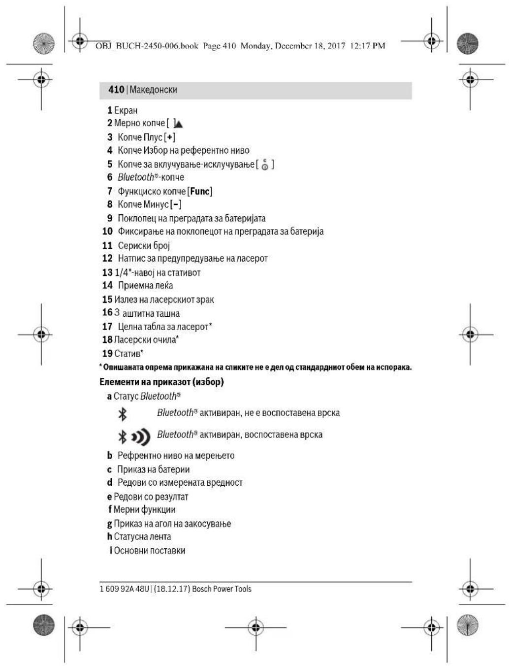

OBJ BUCH-2450-006.book Page 411 Monday, Decembr 18, 2017 12:17 PM


MaKeIaONcKn |411
MOHTAXA
CtabaBe/MeHyBaBe Ha 6aTepeHH
3a pa6oTa co MeHnO TpeD ce npenopauyBa KopHebe Ha aIkaIHO-MaHraHcKn 6abeHH.
Co 1,2-BoNTH6BaTePHN Ce Bo3MOxHH NOMANKy MepeHa OTKONky Co 1,5-BoTTH6BaTePHN.
3a da ro TBOpNE KANAKOT od nperpaData 3a 6atePHN 9nPHNCHEt H MEXAH3MOT 3aKAnyBaHBe 10 NBADeTe r KOANAKOT od nperpaData 3a 6atePHN. CTabete Rn 6atePHN BHTe. PnTHoA BNHMAbaje H NoNOBITE BO corNaCHOCT CO npHKa3OHT H BHTpeSHHATA cTpHa OD nperpaData 3a BATEPHN.
DOKOKNY O3HAKATA 3a Datopejna Ce noJabn 3a npB nAT HA EKPAHOt, MOKHH CE yUHTE OKNY 100 MEpeHa. DOKOKNY O3HAKATA 3a Datopejna e npAHA nTpeNkA UpBeHo, He MOKe J da MepeHte. 3aMeHete Hd BatopeHnO OH. AkyMynatOpHe.
Cekoraa 3amemybajte rncite 6atepnn oedna. Kopctete caMo 6atepnn od een npon3BODHTEN H CO nCT kanaTET.
KOKy He CTo KOHCTene MEPnHOType nobKe BpeMe, H3BaTe Tn 6aTeHNTE OD Hero. KOkny Ce nOIOr BOpe MecknaipAH, BateHNTE MOKe da KOpDnpaAT Da CE nCnpa3HaT.
Ynortpe6a
CtBaHaBe Bo yNtpe6a
He ro octabaje BknyeHnO Mepeyep 6e3 Hnd3Op ncknyeTe ro no ynoTpe6ata. Dpyntte Iina MoKe da ce aaclenat OJnaacepcknot spak.
3aHTTeToMepHOTypeoBnAraHdNpeKTHO H3IOXyBaHe Ha coHcEBN 3pa.
He ro n3noxybajTe MePHHOT ypeHa ekCTpeMHN Temnepatypu HnOcunauu BO TEMnepatypa.Hanp. He ro octabaje doIro BpeMe BO aBtOMoBHOT.Ipn rIoEMn ocunauu BO TEMnepatypata, octabeTe Ro MEHNOT ypeHa hApBPO da ce AknMaTHnPa, npedra o CTaBHe BO yNoTpeBa.Ipn ekCTpeMHN Temnepatypu HnOcunauu BO TEMnpatypata, npueu3HOCTa Ha MEPHNOY peMoKe da Ce HApUYN.
H36erHybaje rnyapate n npBpyBa hata ha mepnhotype. No cnHHn HnBopeuHHn BnJAHJIHa mepHOType, nped Ja ro ynoptpe6hote 3a pa6ota, cekoraw h3bpweTe KOHTPOna Ha ToHcOCTa (BNDn, PpOBepKa Ha ToHocT npn MepeHe h pactoJahna", ctpa422).
Bosch Power Tools 1609 92A 48U| (18.12.17)


OBJ BUCH-2450-006.book Page 412 Monday, December 18, 2017 12:17 PM


412 | MaKeIOnHcNk
BknyBaBe/ncknyBaBe
-3aBknyyBaBeHaMepHnOTypeNnacepOTnpHTncHeteKpaTkoHaKoNcHTo3a MepeHe2[▲].
-3aBknyyBaBeHaMepHnOtypeD6e3Nacep,pntHCHeKpATKOHaKoNcTeo3a BknyyBaBe-HckNyBaBe5[0].
He ro hacouybaje 3paok CBTnHa Ha Hua HxHBOTHN He nOrneHyBaTe DnpeKTHo BO Hero,dypn HOn OJrnoMa oDanaeHeocT.
3aHcknyBaBeHaMepHHOTypeIdpKTe ro konyeto 3a BknyBaHe- NCKJyBaBe5 [ ]npHTnCHATO.
PnH NCKJNUyBaHe Ha MEPHNOT ypeD, BO MEmOpNJATA OCTaHyBaAT 3aUyBaHH BpeHNOCTHe I NOCTABKHe HA ypeDToT.
PpouechHaMepeHe
No BknyuBaHbeto, MepHnOtypee Ce haofo BpyHKunJa ha donKnHcKO mpeHe.3a pyra MepHa pHyHKunja npTINCHETe Ha konHTo 7 [Func].NIsBepeTe ja cakAHata MEPha pHyKunja co KONHTo 3 [+] nIn KONHTo 8 [-] (BnIn ,MepHn pHyHKun" cTpaA 413). AKTHBpaje ja MepHa tpo KUnJa co KONHTo 7 [Func] nIn co KOnHTo 3a MepeHe 2 [▲].
Kako pepepeHTHO HnBO 3a MpeHBe, no BknyuBaHbTeO, e H6paH 3aHnOT pa6 Ha MeHHOT ypeJ. 3a npOMeHa ha pepeepHTHO HnBO BnD ,BnpAHe ha pepeepHTHO HnBO", cTpHa 412.
IocTabete ro MepHnOtypeHa cakahata CTapTHa ToUka Ha MepeHe (Ha np. sWD).
Hanomeha:ДOKOKIy MEpHNoT ypeD CE BkNpyC Ko KOnTuTe 3a BkNpyBaHaBcE NCKIyUBAHBe 5 [ ] npHTnCHeTe KpaTko HA KOnTuTe 3a MepeHe 2 [ ] 3a da ro BkNpyte nacepot.
3aAkhBpaBe HA MepHeTo, npHTNCHeTe KpatKO h KAOnyTo 3a MepHe 2 [▲]. Itoa NacepKnOT 3pk Ke CE NCKnyu. 3a pyTO MepHe NOBtOpE ja OBaa noctAna.
He ro hacouybaTe 3paKOT cBETNHa Ha Hnua HnN XHBOTHn He nornedHyBaTe dIpeKTHO BO Hero,dypn HN OD ronema oDanaeheocT.
Hanomena:BoobnuaeHo,IMpeHATA BpeHocT ce nojabyBa BO pok od 0,5c,a HajdoUHa no OKony4 c. BpEmeTaPaeHTo HA MepeHTo 3aBnH o pactoJAHHeTO, CBETIOCHTE yCIOBn I peFKeTHTpaKu CBOCTBa Ha CEiHa TNOBpuHa. No 3abpyBaHe Ha MepEhtO, Nacepckhot 3apk AABOTATCK Ke Ce NcKluHa.
Bpuhe hapepepehTHo HnBO (BnHcnnkaA)
3a MepeHbTo MoKeJa H36peTe TpN pa3nHnH pepeEHTHn HBOa: 3aHnOpaHa MePHnOyepn (Ha np. npn noCTabyBaHe Ha sIOBn),
160992448U(18.12.17) Bosch Power Tools
Kako pepeepentno Hnbo 3a Mepehe, no BknyuBaHbeto, e n3paan 3aHnOt pa6 Ha MepHHOT ypeI. 3a npomeHa na pepeepHTHO HnBO BnD, BnpaHe ha pepeepHTHO HnBO", ctpaHa 412.


OBJ BUCH-2450-006.book Page 413 Monday, Decembr 18, 2017 12:17 PM


MaKeDoHcKn | 413
- PnpHnOpa6HaMepHnOpyeI(HaNP.npHMepeHe,poHyBaJKnOd eEN pa6Ha Maca).
- cpeHnHa Ha HAOBJOT 13 (Ha np. 3a MepeBa co CTaTb).
3a H360p Ha pepepeHTHO HNBO, pHTHCHHeTo ro KonHeTo 4. Co konHeTo 3 [+] HN KONHeTo 8 [-] HNN KONHeTO 4 H36peTe ro cakAHOTe pepepeHTHO HNBO. No Cekoe BKNYyBaBe Ha MeHNOType, 3aHnOT paB Ha MEPHnOType e npETXoHNOCTABEH KAKO pepepeHTHO HNBO.
MeHH, OCHOBHN NOCTABKN
3a da BneseTe BO MEHHTO ,OCHOBHN NOCTABKN (i), npxETe rnpntchato KOnyeto 7 [Func].
136epete ja oHochata ochOBHa noctabka H Hej3HHOTo nOdecyBaHe.
3a da H3ne3eTe OMeHnTo,OCHOBHN NOCTABKN",npHTNCHETe HA KONHTO 3a BKNyUyBaHe-ACKNuyBaBe5[]
OcbTnyBaHbHaekpaHot
OCBETNYBaHbTo HA ekpHOT e HENPEKHATO BKNUyeHO. DOKONKY HE PnHTHCHe Ha KOnTuO, OCBETNYBaHbTo HA ekpHOT c 3aTeMHyBa NO OKNY 20 cekyHd npAapd aauTITa H aBatePIne/akymyIatopnTE.
MepnФyHKuH
MepeheHaDolXHHH
H36epete mepehe haIOnKHHn I-1.
3a BknyBaBe Ha nacepcknT spak npHTncHete KpaTKo Ha KonTuTo 3a MepeHe 2 [▲]
3a MepeHb npHTCHETe KpATKO HA KOUYETO 3a MepeHe 2 [A].N3MepeHata BpeHocKe ce npKkaeDOny Ha ekpaHOT.
3a ceKoe noHaTAMoHMOpeHe NOBtOpTe rnoRopeHaBeDeHnTe HApOHN. NocNehHATA n3MepeHa BpeHooCT cOnn Dony HaekpaHot, a 8.890 m PpETNOcEHaHn Hea HT
10.160m 11.430m
Mepebe Ha BpeMeTpaebe
Pn KOHTHHypaHO MepeBe, MepHOT yed Moe penaTHBO da ce DBHXK KOU eTtA, npHTo HMepeHATA BpEHOCT Ke aKypHa ha cekO,Oc. Hanp. MoeJa Ce opdaneuHTe Ha keoE pactoJAHne OJ SIOOT, a MOMENTAO pactoJAHne cekorai Ke 6He THTNBO.
Bosch Power Tools 1609 92A 48U| (18.12.17)


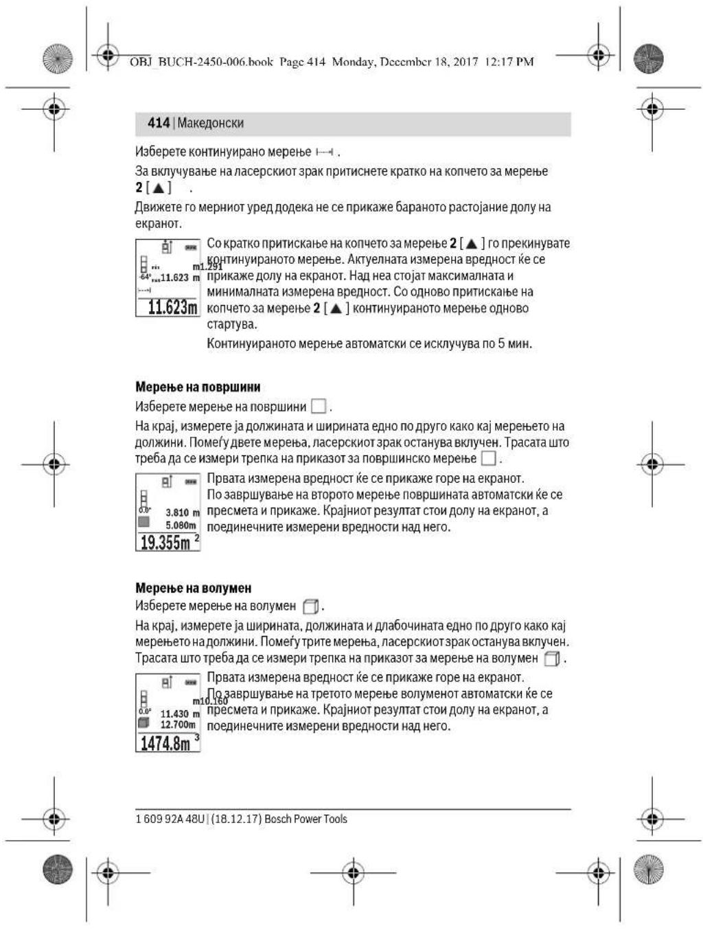


OBJ BUCH-2450-006.book Page 415 Monday, Deccmber 18, 2017 12:17 PM


MaKeIaHcKn 415
HnHneKTHo MepeHe Ha pactoJahna
3aHnHnePKTHMOpeHeHa pactojaHJa,Ha pacnonarahe Bn ce TpH MepHN yHKnn, CO KON MOKe da Ce coonTuT paanuHn Tpacn.
HnDpeKTHOTMepeHe hao pactoJAHJa cnyKHa coonIyBaHe hao pactoJAHJa, KOH neTpe6Da npeKTHO Da ce H3mePat, 6Bnejkn HMa npEeK H BO TEKOT Ha 3paKOT HnHEMa CEHNHOBPIHHa Kako peFNeKToP Ha paCnonaraiBe. Obaa MepHa NocTAnKa MoKeJa Ce npNMeHHcAMo BO BeprNkAeHnpabeu. Cekoe OCTanYBaBe BO XOpH30TaNHe npabeu BoHN KOH MEPHI TpeKKn
HanomeHa: INHINPEKTHOTMepeHe Ha pactojaHHja e cekorau noToHO od DnPEKTHOTMepeHe Ha pactoJAHJa. Bo sABNCHT Ond pnpmeHata, MEPnHTe rpeuMK MoKeJa ce IIOLOEMd INPHEKTHOT MepeHe Ha pactoJAHJa. 3a NIOOBpyBaHe Ha MEPHata ToHOCHT npenopayBAME KOpncTe He h CtaTnB (OnpMeA).
Pomey noeHneHHTe MepeBa,nacepckno3pokocTaHyBa BkIyuHc.
a) NndpeKTHo MepeHe Na BnCnHn (BnDn CnKa B)
H36epete HnHpeKTHo MepeHe Ha BcHNH
BHHMabajte Ha Toa, MepHNoT ypeJa e Ha NcTa BnCnHa Kako HOnHa TMePHaTOyKa. IToa Habanete ro MepHNoT ypeOkOly pepepeHTHO TO HbO HmMepeTe ja Tpacata KAKo Kaj MepHe Ha DonKInHata,1" (Ha ekpaHOT e pnpKaJkaHa Kako uPbeHa nnHna).
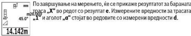
b)ДьоJOнMHДиpeKTHOМepeHbHaBnCHNn(BmHcNnKaC)
MepHnOT ypeJ moEJa Hn H3MePn HnpeKTHO CHTe Tpacn, KOHTo neXaT Ha BEPTKAnIHO To HNO HA MePHNOTypeJ.
136peTe BoJHO HnHpeKTHo MepeHe Ha BcHH.
13MepeTe rTpacHTe KaO npu MepeHe HaDOLHNH,1"H,2"no OoB peOocne.
Bosch Power Tools 1609 92A 48U| (18.12.17)


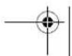


OBJ BUCH-2450-006.book Page 416 Monday, December 18, 2017 12:17 PM


416 | MaKeIoHcKn
c) NdnpkeTHOmepeHeHaDOnkHHN(BHnCnkaD)
I36epete HnDpeKTHo MepeHe Ha doJIKNHH
BHHMaBJte HaToa, MePHNOTypeJaHaHeBaHcHnHa KaKo NbapHaTate MePhaTOka. IToa HABanete Ro MePHNOTyepOKOly pepepeHTHO HnBO N3Mepete ja Tpacata KAKo Kaj MepeBe HaDOnkHHaTa.,1".
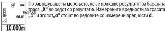
Mepehe Ha sHdHn NoBpHHN (BmHcnnKaE)
MepebeTo Ha SdHn NOBpHHN cnIyKn da ce IobHe 3bnp Ha noBeKe nnoeHNHeHH NOBpHHN Co 3aedHnUka BNCnHa.
Ha npHMePOT co cINKa Tpe6a Da ce OndepiB BkynHata NOBpHnHa Ha NobeKe SNDOBN, KOHmAAATcA Ta BCHnHa Ha npocToPOr H, HO pa3NHnDOnJXHH L.
H36peTe MepeBe Ha SsHn NOBpHNN
H3mepete ja BnCHnHa Ta npocToT H kako npm MpeheTo Ha donKHH.
H3mepehata BpeHocT Ke ce npkKae Bo roPpHOT peHa H3mepEH BpeHocTn.
Iacepot ocTaHyBa Bknyen.
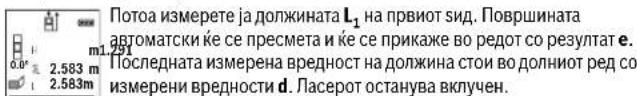
3.336m² CeraH3Mepete jaDOnKHHATA L2 HA BTOPNOT SND.ПпKKaKaHaTа NOeINHeHb VBePNOCT BO peDT Ha H3MepeHN BPeDHOCTd ce DoDAba HA DOnKHHATA L1.Cymata OJ DBETe DOJIKNHH (ПпКakHа BA CpeHnOT peCo H3MepeHN BPeDHOCTd CE MHOKcO c3ayuHATA BNCNHa H.BkynHATA BpeHnCT ha NOBpHnATa Ke ce pNpKaKe XoB peDT co pesyHTaH e.
MoKe Da MePeTe DoJIKNHn No KeJb6Lx, THe ABToMaTcKn Ke ce IooJaat N Ke ce IOMHOkat Co BnCHHata H.
YcNob 3a ToHa IpeCMeTka Ha NOBpUHHHTe e, npBaTa HImpeHa DOnJkHnA (BO pNHPoPOT BmCNHa Ha NpOCTOpOT H) da e nHeTHuHa 3a CnTe DeNoBn Od NobpUHHNTe.
160992448U(18.12.17) Bosch Power Tools


OBJ BUCH-2450-006.book Page 417 Monday, December 18, 2017 12:17 PM


MaKeIoHcKn |417
UpBeHATA cTpeKkOJN. UpBeHOT HATINc Ja pInKaJyBaat peAnHaTa BpeHOT, aKO pepepeHTnAra BpeHOT e HAdBop OeKpaHOT.
Pnka3 Ha 3aayBaHaTa BpeHocT
MaKcHMaJIHnTe 30 BpeJHOCTn (H3MepeHnTe BpeJHOCTn Hn KpaJHnTe pe3yTTaTn) MoKeJa Ce NOBnKaat.
430.16m PnHTNCHErHaKoHcTe8[-],3aJaIpeNCTyBaTeHaHa3aHn3 3aYBaHHeBpHOCTH.
DOKIky BO Memopjata Hema pacnoioxNBA BpeHocT, Dony Ha ekpaHot Ke ce npkaKe ,0.000", a rope ,0".
Hajctapata BpeHocT ce hao'ha Na no3njuja 1 BO MemOpnjata, a HajnoBata BpeHocT ha no3njuja 30 (o3 30 pacnoJIOJIINBm MemOpnpaHI BpeHocTH).PpH 3aUByBaHe Ha BpeHocT cekorai CE bpiue Hajctapata BpeHocT BO MemOpnjata.
BpHneheHaMemOpnaja
3a6pniueheHa cOpjHnHata Ha Memopjata npntCHte Ha KonuTe 7 [Func] H36epete Ja cyHKunjata 3a3auyBaBaBe . IToTa KpaTko npntCHte Ha KonuTe 3a BknyuBaBe-HckNuyBaBe 5 [0] 3aJa Ja H36pniueTe npkaKaHa BpeHocT.
CoHCTOBpeMeHO npnTtckKaHe Ha KONHTo4 H KONHTo3a BKNyUBAhe-NCKNYUBAHe 5 [0]Ke ce H36pHwAT CHTe BpeHcOTHK ONItoCe H aofaat BO MEMOpHaTa.
Co6npahe/0d3emahe Ha BpeHocTH
I3mepeHHTe BpHIOCTH KpaJHTe pe3yNTaTH MoXe da ce co6HpaaT HIN OJ3emaAaT.
160992448U(18.12.17) Bosch Power Tools


OBJ BUCH-2450-006.book Page 419 Monday, December 18, 2017 12:17 PM


MaKeIOnHcKn|419
Co6npaIbe Ha BpeHocTH
Bo cneHnOtn npMmep e ojachTeo co6npaHbTeo Ha nobPunHH:
YbPdTe eHa NoBpuHnHa KaKo WTo e OOnuHa BO DeNoT,MepeHe Ha NOBpHHN", BnD CTpaHa 414.
PnHTNCHeHaKoNcTeO3[+].PipecMeTaHaTaNOBpuHHaN03HaKaTa
MehyBaHe Ha MepHaTa eHHHua
OCHOBHATA noCTaBA e MEPHaTa eHNHa, m" (Metap).
BknyeTe ro MEPnHOTypeI.
Држete ro npintncato konqueto 7 [Func]3a da bne3e Bo MeHTo, OChOBnNoctabkn". H36epete .ft/m".
PnHTHCHETe ro KOnyeto 3 [+] mN KOnyeto 8 [-], 3a da ja npOMeHrte MePhata eHNHa.
3a da n3ne3e oD TOkAra HA MeHnTO, pNTHcHETe Ha KOnHTe 3a BknyBaHe NCKnyBaBe 5 [ ]IIO NCKnyBaBe Ha MepHnOT ypeI, H36paHaT a NoCTaBA ocTaHyBa 3aayBaHa.
Bosch Power Tools 1609 92A 48U| (18.12.17)


OBJ BUCH-2450-006.book Page 420 Monday, December 18, 2017 12:17 PM


420 | MaKeDoHKn
Bluetooth-нтерф ec
PteHoc Ha nodaToCuHa dpyrHupeDn
MepHnOType e onpemeh co Bluetooth®-moyn, koj co nomoi ha paJnoTexnka OBO3MOKyBa IpeHoc Ha noDatoOn Do opeHEn MOBmHn TepMHAn Co Bluetooth®- HHTepFejc (Haip. cMapTfoh, TabNet).
HnfoMaun 3a Notpe6hnte CNTeMCKn npedyCNOBn 3a Bluetooth®-Bpcka Ke HajdTe Ha HHTepHET CTpaHata Ha
Bosch Ha www.bosch-pt.com
OCTaHaTHTE HnHOpMaun Ke rH npOHajTe Ha cTpaHATA 3a IPOH3BOoT OJ Bosch, BnTe Ro QR-KoToT, cTpaH a 8.
Pn npneoc Ha noaToOn Co nOmoH a Bluteoth MoKe da HactaHAT BpeMeHcKn OndoxyBaHa NOMery MObHnHOT TepMHnHn MepHnOType.ObaMOke da ce cnuyu nopadn OndaneHeOCTa HaDBATA ypeHnNN CamHOT MepeH Objekt.
AkrnBpahe Ha Bluetooth- HHTeppejc 3a npehoc Ha noataou Ha moHNHe TepMHHJ
3aakTNbpahe Ha Bluetooth®-HnTepfejcoT npTnCHeHa Bluetooth®-KoNteto 6 Ha MepHNOYpeI.3aakTNbpahe Ha Bluetooth®-CnHAnOT npTnCHeTe OJHOBO Ha Bluetooth®-KoNteto 6 mnn KOnToe 3 [+]. NpOBepe TaNN Bluetooth®-HnTepFejcoT e aKTHBpaHn Ha BAunot MObnen TepmHaJI.
3a Hndpa6ha 06emot Ha dyHKun Ha MoBHINOT TepMHAN Hs 3a noednoctabyaBe Ha o6pabokkata Ha noDatoun Ha pacnolanahe IMate cneunjannH Bosch-anlkaun (Apps). The moe da ce peseMaT Bo cooDBeHTHe npOabHNu BO 3ABHCHOT OJ TEPMHANOT.
IocapHa Bosch-annHkauijata Ce BocnoctaByBa Bpcka NoMeFy MoBnHnot TepMNHaI MePHNOT ypeJ. DOKONky ce npohajdeHn NOBeke AKTHBnH MeHN ypeHn, H36epeTe rcooDBeHTHNot MeEH ypeC o IMOw Ha cepNCKnT 6poj.
Ctaycot Ha noBpyBaBe KaKo n AKTNBHata Bpcka (a) Ke ce npHKaKat Ha CtayChata HnHa (h) Ha MepHHOType.
JaekTHBnpaHbHa BluteothmHTpejc
3a DeakthBnpaHe Ha Bluetooth®-Bpckata npntnche Ha Bluetooth®-KonHcTo 6.3a DeakthBnpaHe Ha Bluetooth®-CnHAnOT OJHOBO IpHNTCHe Ha Bluetooth®-KonHcTo 6 NIN KOnHcTe 8[-]NIN NCKIyHcTe rO MePHNtypeD.
Cobetn npnaaboTebeTo
OCTaHaTHTE HnFOpMaun Ke rH npOHajTe Ha cTpaHata 3a npOH3BOoT OJ Bosch, BnTe ro QR-KoToT, cTpHa 8.
160992448U(18.12.17) Bosch Power Tools


OBJ BUCH-2450-006.book Page 421 Monday, December 18, 2017 12:17 PM


MaKeIdoHcKn | 421
MepHnO type e onpeMe co 6e3KHeu HHTepfejc. Tpe6a da c BeHHmaba Ha IokaJIHnTe OpeaTHBnO rpaHnuBaHa, Ha np. Bo ABHOHN Hn60JIHn.
OnuTH HANOMEH
PnHmHaIeKa14Hn3ne30HaIacepcknot3paK15HeCMeatda6nataNOKPHeHH 3aBpeMeHaMepeheto.
3aBpeMeHaMepeHbeto,MEpHNoTpyedHe CmEE da ce DnKn.10kONky e BO3MOxHO, NOCTABeTe ro MEPHNO TyeHa UcBpTa NODora.
BnjjnjaHa Mephoto none
MepHOne none 3aBHCn OCBETNOCHNTE yCLOBn N peDfNEKTHNBHTe CBOJCTBa HA ueHATA nobpuHNA. Pp Jako HADBPOeHOBOCBETNYBaBe, 3a noDobpa BHNIOBCT Ha nacepckNOT3kap, KopHcTeTe 3auHTTNHOnuHna 3a nacep18 (onpema) u eHnHa Ta5b3 aNacep0T 17 (onpema), nn 3aceHene ja eUHnata nobpuHNA.
BnnaHaHa MePnHTope3yntar
IopadnФH3NCHe eEeKTHe MoKte Da CE NcKInyuNΦAKTOT,DEKa npH Mepeheto Ha pa3nnHNOBpuHHNoaTaNoIorpeuHO MepeHe.Tyka cnafaat:
TpaHcnapeHTN NOBpWHN (Hanp. cKaIO, B0a),
- NOBpshnnH WTo peFneKTHpaat (HaNP. HcNoIHpAaM TaKIO),
- nop03Hn NOBpUHHn (Ha np. 3ONaqHOH MaTepnjAnu),
- ctpyKtpypanHH nobpHNN (Ha np. rpybMaTpeHja, npnpoDeH kamen).
DOKONky e BO3MOxHNO, HA OBHe NOBpHHN KOpHCTe ueHa Tabna 3a NacepOT 17 (onpeMa).
IpeuKN PnH MepeHeTo Ce HCTa Ka MoXHH Kaj HaKOCBnHaHn CEHN NOBPWHN.
IcToTakaHaMePHTA BpeHCTMOKe DaBnJaATNpOeHNrTe3aBeHTNaJca Co pa3nnHnTemnepaTyPN HnHnDnpeKTHo pnpMeHnTe peFneKcn.
PpOBePKaHaTOUHOCTaKANH6pHpAbeToHaN3MepeHHTe KocHH (BnH CNHkA G)
PepOBHn npObepyBajre ja ToOHocTa ha MpeHbeto HaKocHH. OBa c BpuH co NOMou HA MeHbAbe Ha npabeOT. NcOtabe Ro MpeHNOt yPeE Ha ENa Maca H3Mepete Ja KOCNATA.CBpTe ro MePHNt ope 3a 180^ nOHOBO H3Mepete ja KOCNATA.
Pa3NNkata nomety pnpKaXaHnTe h3OCh Cmee da H3HeCyBA MaKc.0,3°
Pn rnoemn otctanyBaHa MePHNOTypeMopa OOnHO Da ce KaHbnpa. Pnptoa 36epete TneTn ynaTcBata Haekpahot.
No rolemn npomenn Ha Temnepatpata n no ydapn, npenopaybame da ce hBpuin Nopebka Ha ToCHoCTa n Ee. KaHOBpHaBe Ha MepHOT ypeD. Iio npomeHa Ha TemnPATpata, MepHOT ypeD mOpA da ce pnilarOg n Ha HOPMaHATA temnepatpa HeKoe BpeMe nped Da CE hBprn KaHbpaunja.
Bosch Power Tools 1609 92A 48U| (18.12.17)


OBJ BUCH-2450-006.book Page 422 Monday, December 18, 2017 12:17 PM


421 MaKeIOnHcNk
IpoBepkaHaToHocTnPHMepeHeHa pactoJahnja
ToHocTaHaMepHnOypeMoKeJa ja npOBepHe Ha CneHNOB HauHH:
I36peTe eHNO HENPOMeHNBO MepHO NOpaJc co OJONKHa oKoNy 3do 10M, YNJa DOJNKHa TOHO Ja 3HaTe (HaNP. UINPHATA Ha NpOCTOPjAta, OTBOPOT Ha Bpata). MepeHeTo TpeBa da Ce BPN npu NobOnn yCNoBn, T.e. MePHTO NoPaJcpe TpeBa da 6Bue BO HATPeUNHOTnpocTOp nEuaHATA NobPIHHa Ha MepeHeTo TpeBa da 6Bne Ma3Ha nDobpo da pePneKtnpa.
H3mepete ro noopaujero 10-natn eoHno npdyro.
OTCTanyBaHetoOp cpeDhata BPeNDocPnPi NooeiHneuHInte MepeBa CMeE da H3neCyBa MckCMYM ± 4 MM ha CEIoTO MEpHO pNOpaJe PnI NOBHN yCNOBn. 3aNHyBaJaTe FN MepeBa,ta, da Ja MoEs IpOnOuaHa da Ja cNopeDiTe TOUHOcta.
Pa6oTeHe co cTaTHB (onpeMa)
KopHCTeBeto Ha CTaTHBOT e Oco6eHO IOTpe6HO npn rOnemn pactoJAHJa. MePHNOT yepeCo 1/4"-HabOj 13 NoCTABete Fo Ha 6p30 npOMEHnBa IIIOHa HA CTaTHBOT 19 Hn HA BOObuaeh FOto-CTaTH. LBPcTo 3aWpaPefete ja 6p30 ZAMEHnBA tIIIOHa co WpaF 3a ZIKCnPaHe.
CooDBeTHO NOCTABETROpepepeHTHOTo HNBO 3a Mepehe Co CTaTHBOT, CO npTnCKaHe Ha KOnTuE To 4 (pepepeHTHO HNBO 3a HAOBJ).
Iopaka 3a rpeuka
DOKONKY MEPEBETO HE MOK Da CE npABINHO Da CE HBAPIH, HA EKPANOT Ce npKAKyBa Nopakata 3a rpeuKa, Error'. IcknyeTe Ro MEPHOT yed IN NOBTOPO BKNYte Ro nOdoHO CTAPTyBaTe Ro MEPEbeto.

MepHnOT ypeJ ja KOHTpONIPA TOHATA yHyKUNa Jpi nCekoe MpeHe.
DOKOKKY CE YTBPN DEpEKT, HA EKPANOT CTOn CAMO O3HAKATA NOKPAJ
HERo HmEPHnOT ypeJ CE NCKnyyBa. Bo BAKOB CNYaj npedAte ro
BauHnOT mepen ypeJ ppeky Baunot TProBEu Ha cepBnCHata cnykba
Ha Bosch.
OdpKyBaBeH cepBnC
OdpxkyBaHe nHcTehe
IocjoJano OOpKByaTe ja ChToTata Ha MeHnOT ypei.
He ro tonOyBaTe MeHnOTypeB BOda Hn DpyrTeuHocTn.
H36pHwete r HeHcCTOTmTE Co BnaXHa MeKa KpNa. He KopHcTeTe cpeCTBa 3a
YncTeHe Hn PaCTbOpN.
160992448U(18.12.17) Bosch Power Tools


OBJ BUCH-2450-006.book Page 423 Monday, Decembr 18, 2017 12:17 PM


MaKeIdoHcKn|423
Ocboho Odoxybaje ja npemnata neka 14 co nctata rpnka, co koja Tpe6a da ce oDpybaat Ounnata nnnekata Ha foToanapat.
Bo cnuyaj da tpe6a da ce nonpaBn, npateTe ro MepHnotypeD Bo 3aunTHata Tauna
CepBncha cnyy6a n COBET np KOpHCTeHe
CepBnchata cnjx6a ke OJROBOpHa BaWnte npaaHb Bo Bpca co nonpaBkata nOdpKyaBaHTo Ha BaINOT pOn3BOD kako H pe3EBHIne DeIOBN. EKcIIO3NBeHUPTeK HnHfOpMaun 3a pe3EBHn DeIOBN Ke hajTe Na:
www.bosch-pt.com
THMOTaCoBcYBaIbe npn KOpHcTeIbe Ha Bosch Ke BN NOMORHe DOKOLKy HMaTe npaaHa 3a HauWte npOn3BODn HOnpeMa.
3a cIte npaaaba n hapaKHa pe3epBn DnelOBn,Be monmHe HabeTe ro 10- uHpHnO6oJcneuHnKaunHata PIOUka Ha IPOIN3BOIoT.
MaKeDoHnJa
Д.Д.Ектпс
CabaKobayek47H,6poj3
1000 Ckonje
E-nouta: dimce.dimcv@servis-bosch.mk
HHTepHer: www.servis-bosch.mk
Ten./fəkɑc:02/2467610
Mo6.:070595888
OtctpaHyBaHe
Mepnhte ypei, onpemata n ambaanke Te pbea da ce otctpaH a ekonoowkn npnhafnHBnH.

He n pfnpajte MepeHnte ypeiN 6aTepeHnte BO DoMaIHaTa KaHTa 3a ry6pe!
Cama 3a 3emju Bo pamku Ha EY
Cnped ebponckata perynata 2012/19/EU mepnte ypei nto ce boh ynoTpe6a
HnekeTHNE HN hckopncTeHe 6atepn hncped perynatmbata 2006/66/EC
Mopa oDJIHO da ce cobepaHa ca peuknpaat 3a noBtropHa ynoTpe6a.
Ce 3aDpKyBa npaboto Ha npomema.

Bosch Power Tools 1609 92A 48U| (18.12.17)


OBJ BUCH-2450-006.book Page 424 Monday, December 18, 2017 12:17 PM


424 Srpski
Srpski
Uputstva o sigurnosti

Morate da prociitate i obratite paznju na sva uputstva kako bistie sa altom radili bez opasnosti i bezbedno. Ako merni alat ne upotreblavate u skladu sa prilozenim uputstvima, mozte da ugrozite zaistne mere koje su integresiune u merni alat. Nemojte da dozvolte da ploce sua upozorenjima budu nerazumljive.
DOBRO SACUVAJTE OVO UPUTSTVO I PREDAJTE GA ZAJEDNO SA ALATOM, AKO GA PROSLEDUJETE DALJE.
- Oprez - ako se koriste drugi uredjaji za rad ili povesavanje od onih koji su ovde navedeni, ili izvode drugi postupci, moze ovo voditi eksplozijama sa zračenjem.
Merni alat se isporucje sa Jednom upozoravajucom tablicom (u prikazumernog alata označena na grafickoj stranici sa brojem 12).
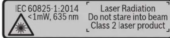
Ako tekst tablice sa opomenom nije na Vasem jeziku, onda prelepitge pa prerpvog pustanja urad sa isporucenom nalepnicom na jeziku Vase zemJIe.

Ne umeravaraje laserski zrak na osobe ili zivotinje i siame negledajte u direktran ili reflektujiča laserski zrak. Na taj nacin要去 de za slepite lica, prouzrokujete nezgode ili da ostetite oci.
Ako lasersko zracenje dode uoko, morate svesno da zatvorite oki i da glavu odmah okrenete od zraka.
Nemoje da vrsite promene na laserskoj opremi.
Ne koristite laserske naocare za posmatranje kao zastitne naocare. Laserske naocare za posmatranje sluze za bolje prepoznavanje laserskog zraka, one ne stite od laserkog zracenja.
160992A48U(18.12.17) Bosch Power Tools


OBJ BUCH-2450-006.book Page 425 Monday, December 18, 2017 12:17 PM


Srpski|425
Ne upotrebljavaje laserske naocare za posmatranje kao naocare za sunt ilu putnom saobracaju. Laserske naocare za posmatranje ne pruzaju punu UV zastitu i smanjuju opazanje boja.
Neka Vam merni alat popravlja strucno osoblje i samo sa originalim rezervnim delovima. Time se obezbedjuje, da sigurnost mernog alata ostaje sačuvana.
Ne dopu staje deci korijscenje mernog alata sa laserom bez nadzora. Oni bi mogli nenamerno zaslepiti osoblje.
Ne radite sa ernim alatom u okolini ge postoji opasnost od eksplozija, u kojo se nalaze zapaljive tecnosti, gasov ili prase. U mernom alatu se mogu proizvesti varnice, koje bi zapalite praseiu ilisiparenja.
Oprez! Ako upotreblavate merni alat sa Bluetooth®bove da nastupi smetnja za druge uredeje i postrojena, avione i medicinske uredeaje (npr. pejsmejkere za src, slusne aparate). Takode NIe sasvim iskljucen negativan uticaj na ljude i zivotinje u neposrednoj blizini. Merni alat sa Bluetooth® nemoje da upotreblavate u blizini medicinsikh uredeaje, pumpi za tocenje goriva, hemijskih postrojena, zona sa opasnošću od eksplozije i minskih polja. Merni alat sa Bluetooth® nemoje da upotreblavate u avionima. Izbegavaje režim rada na duži vremenski period u direktnoj blizini Tesla.
Bluetooth® naziv marke kao i silkovne oznake (logotipi) su registrovane robne\ marca i vlasnišvo Bluetooth SIG, Inc. Svaka upotreba ovog naziva\ marca/slikovnilh oznaka od strane Robert Bosch Power Tools GmbH vrsi se pod licencem.
OBJ BUCH-2450-006.book Page 427 Monday, December 18, 2017 12:17 PM


Srpski|427
Digitalni laserski merac rastroanja GLM 50 C
| Prenos podataka | |
| Bluetooth®Bluetooth® 4.0 | (Classic i Low Energy) (G) |
| Opseg radne frekvencije 2402 - 2480 MHz | |
| Maks. prenos snage | 2,5 mW |
A) Prilkom merena od prednje ivice mernog alata, za visoku moć refleksije cilja (npr. zid okrečen u belo) važi slabo osvetljene pozadine 125 °C radne temperature. Dodatno morate da računate na odustpanje od ± 0,05 mm/m
B) Prilkom meranja od zadnje ivice mernog alata, važi za veliku moře refleksije cilja (npr, beli karton), jako osvetljenje pozadine i - 10°C do +45°C radne temperature. Dodatno morate da računate na uticaj od ±0,15 mm/m.
C) Nakon korisnicke kalibracije na 0^90^ mora da se uzme u obzir dodatna greka uspona od ± 0.01^ /stepeni do 45^ (maks.). Kao referentna ravan za merenje nagiba sluzi leva strana mernog alata.
D) na 25^ radnojtemperaturi
E) U funckiji trajnog merenja iznosi maks. radna temperatura +40^ .
F) izuzimajuci pregradu za bateriju
G) Kod Bluetooth® Low Energy uredaja u zavisnosti od modela i operativnog systemdus uspostavljanje veze moe da bude nemoguce. Bluetooth® uredaji moraju sa podrzavaju SPP profil.
H) Bluetooth® deaktiviran
Zajasnijut identifikaciju Vaseg mernog alata sluzi seriji broj 11 na tipskob tablici.
Komponentesa slike
OBJ BUCH-2450-006.book Page 429 Monday, December 18, 2017 12:17 PM


Srpski|429
Kada se prvi put na displeju prikaze simbol prazne baterije, tada su moguca još otprilike 100 merenja. Kada je simbol baterije prazan i treperi crveno, tada su onemogucena dalja merenja. Zamenite baterije odnosno akumulatorske baterije. Menjate uvek sve baterije odnosno akumulatore istovremeno. Upotrebljavaje samo baterije ili akumulatore jegnog proizvodjača i sa istim kapacitetom.
Izvadite baterije odnosno akumulatore iz mernog alata, kada duze vremena ne koristite. Baterije i akumulatori mogu kod duzeg cuvanja korodirati i same se isprazniti.
Rad
Pušanje urad
Ne ostavlajte slucajno ukljucen merni alat iskljucite merni alat posle upotrebe. Druge osobe bi mogle da budu zaslepljene od laserskog zraka.
Cuvajte merni alat od vlage i direktnog suncevog zracenja.
Ne izlazite merni alat ekstremnim temperaturama ili temperaturim kolebanjima. Ne ostavlajte ga na primeru autu duze vreme. Pustite merni alat pri vecim tempaturnirk molebanjima da se prvo temperira, pre nego ga pustite u rad. Pri ekstremnim temperaturama ili temperaturim kolebanjima moze se ostetiti preciznost merog alata.
Izbegavaje jake udarce ili padove mernog alata. Posle jakih speljinih uticaja na merni alat trebali bi uvek pre daljeg rada izvrsti kontrolu tačnosti (pogledajte „Kontrola tačnosti pri merenju rastojanja“, stranicu 438).
OBJ BUCH-2450-006.book Page 434 Monday, Dcccmber 18, 2017 12:17 PM


434 | Srpski
Izmerite visinu prostoru H kao kod merenja duzine. Merna vrednost ce biti prikazana u gornjem redu za merne vrednosti. Laser ostaje ukljucen.
Onda merite duzinu L1 pvogzida. Povrsina se obraucnati automatski i prikazije se u redu za rezultate e. Posledna izmerena vrednost duzine stoju u donjem redu za merne vrednosti d. Laser ostaje ukljucen.
L 2.583m Sada izmerite duzinu L2 drugog zida. Pojedina cna merna vrednost koja 3.336m2 je prikazana u redu za mernu vrednost d sabira se u duzinu L4. Zbir obe duzine (prikazanh u srednjem redu za mernu vrednost d) mnozi se sa
memorisanom visinom H. Vrednost ukupne povrsine prikazuju u redu zu rezultat e. Po zeJI mozete da merite mnogo drugih duzina Lx, koje se automatski sabiraju mnoze sa visinom H.
Preduslov za korektno izracunavanje povrsine je da prva izmerena duzina (visina u prostoru H) bude identica na sve povrsine delova.
Funkcija nivelisanja (pogledajte sliku F)
Funkcija nivelisanja ponovljivo meri definisanu duzinu (deonicu). Ove duzine mozete da prenesete na povrsinu kako biste NPR. omogucil secenje materijala veoma velikh komada ili opremili noseze zidove u pregradivanju prostora. Podesiva minimalna duzina iznosi 0,1 m, maksimalna duzina Iznosi 50 m.
Upstvo: U funkciji nivelisanja se prikazuje odstojanje u odnosu na obelezejna displeju. Ivica mernog alata njreferentna.
Izaberefte fungciju nivelisanja
Podesite Željenu duzinu. Za to pomoću tastera 7 [Func] izaberite odgovarajuće cífre/mesto i promenite vrednost pomoću tastera 3 [+] ili tasterom 8 [-].
Startujte fungkciu nivelisanja pritiskom tastera za merenje 2 [▲], i polako se udaljavaje od startne tačke.
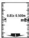
Merni alat kontinuirano meri razmak do startne tacke. Pritom se priakazu definisana duzina kao i aktuelna merna vrednost. Donja odnosno gornja strelca prikazuje najmanju udalenost do sledeceg odnosno poslednej teg markera.
Upstvo: Prilikom kontinuiranog merenja pritiskom na taster 4 takode mozte da utvrdite izmerenu vrednost kao definisanu duzinu.
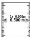
Levi faktor navodi kolko Često ste vec postigli definisanu dužinu. Zelene strelce sa strane na displeju prikazuju postizanje dužine za svru markiranja.
OBJ BUCH-2450-006.book Page 437 Monday, December 18, 2017 12:17 PM


Srpski 437
Informacije o neophodnim preduslovima za system za Bluetooth® vezu nacićete na Bosch internet stranici na www.bosch-pt.com
Ostale informacije cete pronaci na stranici za Bosch proizvode, videti QR-kod, strana 8.
Prilikom prenosa podataka pomocu Bluetooth® mogu da nastupe vremenska odlaganja izmedu mobilnog finalnog uredaja i ernog alata. To moze da bude zbog udalenosti oba uredaja u odnosu jegan na drugi ili zbog samog ernog objekta.
Aktiviranje Bluetooth® porta za prenos podataka na mobilni finali uredaj
Za aktiviranje Bluetooth®-porta pritsinite Bluetooth®-taster 6 na mernom alatu. Za aktiviranje Bluetooth®-signala iznova pritsinite Bluetooth®-taster 6 ili taster 3 [+]. Uverite se, da je Bluetooth® port na Vašem mobilnom finalnom uredaju aktiviran.
Za prosirenje obima funkcije mobilnog finalnog uredaja i za pojednostavlenje obrade podataka na raspolaganju stoje specijalne Bosch applikacije (Apps). U zavisnosti od finalnog uredaja mozte da in preuzimate u odgovarajuca memorjska skladista.
Posle starta Bosch applikacije uspostavlja se veza izmedu mobilog finalog uredaja i mernog alata. Ako ste pronaši više aktivnih mernih alata, izaberite odgovarajuči merni alat pomoću serijskog broja.
Prikazuju se status veze kao i aktivna veza (a) u statusnojlestvici (h) mernog alata.
Deaktiviranje Bluetooth® porta
Za deaktiviranje Bluetooth®-veze pritsnite Bluetooth®-taster 6. Za deaktiviranje Bluetooth®-signala iznova pritsnite Bluetooth®-taster 6 iili taster 8 [-] ili iskligute merni alat.
Uputstva za rad
Ostale informacije cete pronaci nastranicza Bosch proizvode, videti QR-kod, strana 8.
Merni alat je opremljen radio portom. Morate da obratite paznju na lokalna ogranicenja u rezimu rada, npr. u avionima ili bolnicama.
Opsta uputstva
Prijemno socivo 14 i izlat laserskog zraka 15 ne smeju bittiPokriveni pri merenju. Merni alat tokom merenja ne smete da pomerate. Iz tog razloga merni alat polozite sto je moguce blize fiksnoj granicoj povrsini ili povrsini za polaganje.
Bosch Power Tools 1609 92A 48U| (18.12.17)


OBJ BUCH-2450-006.book Page 438 Monday, December 18, 2017 12:17 PM


438 | Srpski
OBJ BUCH-2450-006.book Page 439 Monday, December 18, 2017 12:17 PM


Srpski|439
Radovi sa stativom (pribor)
Korišćenje stativa je posebno potrebna pri vecim rastojanjima. Stavite merni alat sa 1/4^* -navoja 13 na brzo promenljvu plocu stativa 19 ill nki foto stativ uobicaj u trgovini. Črsto uvrnite sa zavrtnjem za fiksiranje brzo promenljve plocé. Podesite premate osnovnu ravan za merenje sa stativom pritiskujuci taster 4 (navoj osnovne ravni).
Javljanegreske
Ako merenje ne mozte da izvrsite korektno, poruka o greski „Error“ se prikazujne na displeju. Isklujcite merni alat i ponomovo ukljucite i iznova startujte merenje.

Merni alat vrši nadzor ispravn FKncjce prilikom svakog merenja. Ukoliko se utvrdi kvar, dispiejPokazju samo još samo simbol koji se nalazi pored, a merni alat se isključuje. U tom slucaju merni alat preko Vaseg distributera dostavite Bosch servisnoj lužbi.
Održavanje i servis
Održavanje i cisćenje
OBJ BUCH-2450-006.book Page 441 Monday, December 18, 2017 12:17 PM


Slovensko|441
Slovensko
Varnostna navodila

Do not stare into beam
Class 2 laser product
- Ce tekst opozorilne tablice ni v vašem jeziku, ga pred prvim zagonom prelepi-te zustrezno nalepko v vašem nacionalnem jeziku.

OBJ BUCH-2450-006.book Page 442 Monday, December 18, 2017 12:17 PM


442 | Slovensko
OBJ BUCH-2450-006.book Page 444 Monday, December 18, 2017 12:17 PM


444 | Slovensko
A) Pri merjenju od spednjega roba meriline naprave velja za visoko obojnost ciljne povrsine (npr. prebeljena stena), sibko osvelitjev ozadja in delovno temperato 25 °C. Prav takto treba upostevati od stopanje ± 0,05 mm/m.
B) Meritev od zdnjega roba merine naprave velja za velik odboji od cijne povrsine (npr. bel karton), mochn osvetlitve in delovno temperaturo od - 10^ do +45^ . Dodatno je treba upostevati vpiiv ± 0.15mm / m
C) P o umerjanju pri 0^ in 90^ je treba upostevati dodatno napako nagiba ± 0,01^ /stopinjo do najvec 45^ . Kot referencna ravnina za merjenje nagiba se uporablja leva stran merilne naprave.
D) pri 25^ delovni temperaturi
E) V funckijtrajnegamerjeranja znaša maks.delovnatemperatura +40^
F) razen predala za baterije
G) Pri nzikoenergjsikn napravah s funkcijo Bluetooth® glede na model in operaciji system morda ni mozv postavite povezave. Naprav s funkcijo Bluetooth® morajo podpirati profil SOP. H) Bluetooth® je izkjučen
Jasno identifikaciono VaSega merilnega orodja omogocara serijska stevilka 11 na tipski plostici.
Komponente na sliki
OBJ BUCH-2450-006.book Page 445 Monday, December 18, 2017 12:17 PM


Slovensko | 445
OBJ BUCH-2450-006.book Page 446 Monday, December 18, 2017 12:17 PM


446 | Slovensko
Delovanje
Zagon
OBJ BUCH-2450-006.book Page 447 Monday, December 18, 2017 12:17 PM


Slovensko | 447
Za zacetek merjenja pritsnite tipko za merjenje 2 [▲]. Zatem se laserski zarek izkjiči. Za novo meritev ponovite ta postopek.
OBJ BUCH-2450-006.book Page 448 Monday, December 18, 2017 12:17 PM


448 | Slovensko
Pri vsaki meriti poinovite zgoraj navedene korake. Zadnja izmerjena yrednost je navedena na prikazovalniku spodaj, predzadnja nad njo itd. 8.890 m 10.160m 11.430m
Stalna meritev
OBJ BUCH-2450-006.book Page 452 Monday, December 18, 2017 12:17 PM


452 | Slovensko

OBJ BUCH-2450-006.book Page 453 Monday, December 18, 2017 12:17 PM


Slovensko | 453
OBJ BUCH-2450-006.book Page 455 Monday, December 18, 2017 12:17 PM


Slovensko | 455
Vpliva na rezultat meritve
OBJ BUCH-2450-006.book Page 456 Monday, December 18, 2017 12:17 PM


456 | Slovensko
Delosstativom(pribor)
Se posebej pri vecijh razdaljah je njuna uporaba stativa. Postavite merilno orodje s 1 / 4^n -navojem 13 na menjalno plošco stativa 19 ali na obicajni komercialni fotostativ. Privijte ga z nastavitvenim vijakom menjalne plošce.
Ustrezno referencno ravnino za meritev s stativom nastavite spritiskanjem tipke 4 (referenčna ravnina je navoj).
Sporocilo napake
Laser Radiation Do not stare into beam Class 2 laser product
Ako tekst natpisa upozorenja nilje na vasmaterinjem geziku, u tom slucaju prije prvog pustanja urad, preko ovog natpisa upozorenja nalijepite isporuce-nu naljepnicu na vasmaterinjem geziku.
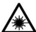
OBJ BUCH-2450-006.book Page 459 Monday, December 18, 2017 12:17 PM


Hrvatski | 459
OBJ BUCH-2450-006.book Page 462 Monday, December 18, 2017 12:17 PM


462 | Hrvatski
18 Naocale za gledanje lasera*
19 Stativ*
- Prikazan ili opisan pribor ne pripada standardnom opsegu isporuke.
OBJ BUCH-2450-006.book Page 464 Monday, December 18, 2017 12:17 PM


464 | Hrvatski
OBJ BUCH-2450-006.book Page 467 Monday, December 18, 2017 12:17 PM


Hrvatski 467
Nakon zavrsenog mjerenja u retku reztulatae pokazat ce se rezutat za
12.208
45.0
8.765m Pazite da referenta ravina mjerenja (npr. strznji rub mernog alata)
kod svih pojedinachni mjerenja u toku jegnog postupka mjerenja ostane na tocno istom mjectu.
OBJ BUCH-2450-006.book Page 468 Monday, December 18, 2017 12:17 PM


468 | Hrvatski
OBJ BUCH-2450-006.book Page 469 Monday, December 18, 2017 12:17 PM


Hrvatski | 469

OBJ BUCH-2450-006.book Page 470 Monday, December 18, 2017 12:17 PM


470 | Hrvatski
Pritisnite tipku 3 [+]. Prikazuju se izracunata povrsina i symbol + .
Pritisnite tipku za mjerenje 2 [▲], za zapocinjanje mjerenja druge povrsine. Uvtrdite povrsnu sukladno odlomku Mjerenje povrsina, vidi stranicu 465. Kada je zavrso do drugo mjerenje, rezultat drugog mjerenja povrsine priakuzije do dolje na displeju. Za prikaz konaçnog rezultata ponovno pritsnite tipku za mjerenje 2 [▲]
Napomena: Kod mjerenja duzine konačni rezultat se odmah prikazuje.
OBJ BUCH-2450-006.book Page 471 Monday, December 18, 2017 12:17 PM


Hrvatski | 471
Prilikom prijenosa podataka pomocu Bluetooth- a^老 moze doci do kašnenja izmedu mobilog terminalnog uredaja i mjernog uredaja. Razlog tome moze biti u medusob-noj udalenosti oba uredaja ili u samom objektu mjeranja.
Aktiviranje Bluetooth²-sucelja za prijenos podataka na mobilni terminalni uredaj
Za aktiviranje Bluetooth®-sucelja pritsnite Bluetooth®-tipku 6 na mjernom alatu. Za aktiviranje Bluetooth®-signala ponovno pritsnite Bluetooth®-tipku 6 ill tipku 3 [+]. Provjerite da li je na vasm mobilnom terminalnom uredaju aktivirano Bluetooth®-sucelje.
Za proširenje opsega funkcija mobilnog terminalnog uredaja i radi pojednostavljenja prijenosa podataka na raspolaganju su spejcalne Boschove apilkacije (Apps). Ovisno o terminalnom uredaju要考虑 ih preuzeti iz odgovarajučih online prodavaonica (Stores).
NakonPokretanja Bosch-aplikacija uspostavlja se veza izmedu mobilog terminalnog urenda i mjernog alata. Ako se pronade visaktivnih mjernih alata, odaberite odgovarajuCi mjerni alat pomocu serijskog broja.
Stanje veze kao i aktivno spajanee a) pojavit ce sa statusnoj traci (h) mjernog alata.
OBJ BUCH-2450-006.book Page 472 Monday, December 18, 2017 12:17 PM


472 | Hrvatski
OBJ BUCH-2450-006.book Page 475 Monday, December 18, 2017 12:17 PM


Eesti475
Laser Radiation Do not stare into beam Class 2 laser product
OBJ BUCH-2450-006.book Page 476 Monday, December 18, 2017 12:17 PM


476 Eesti
OBJ BUCH-2450-006.book Page 481 Monday, December 18, 2017 12:17 PM


Eesti481
OBJ BUCH-2450-006.book Page 482 Monday, December 18, 2017 12:17 PM


482Eesti
Pidevmootmine
OBJ BUCH-2450-006.book Page 483 Monday, December 18, 2017 12:17 PM
483
OBJ BUCH-2450-006.book Page 485 Monday, December 18, 2017 12:17 PM


Eesti 485
OBJ BUCH-2450-006.book Page 486 Monday, December 18, 2017 12:17 PM


486|Eesti

OBJ BUCH-2450-006.book Page 487 Monday, December 18, 2017 12:17 PM


Eesti487
OBJ BUCH-2450-006.book Page 489 Monday, December 18, 2017 12:17 PM
489
OBJ BUCH-2450-006.book Page 490 Monday, December 18, 2017 12:17 PM


490 | Eesti

Laser Radiation Do not stare into beam Class 2 laser product
Ja bridinosas uzlimes teksts nav jusu valsts valoda, tad pirms pirmas lietoanas parlimejiet tai pari kopa ar merinstrumentu piegadato uzlimi jusu valsts valoda.
Bosch Power Tools 1609 92A 48U| (18.12.17)


OBJ BUCH-2450-006.book Page 492 Monday, Decembr 18, 2017 12:17 PM


492 | Latviešu
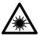
Neversiet lazera staru citu personu vai majdzivnieku virziena un neskatielies tlesaja val atstarotaja lazera stara. Sada riciba var apzilbinat tuvuma esosas personas, izraisit nealimes gadijumus vat pobjat redzi.
- Ja lāzera starojums noklust acis, nekavejotles alzveriet tās un parvietojiet galvu tā, lai tā atrastos ārpus lāzera stara.
Neveiciet nekadas izmainas ar lazera ierici.
Nelietojet lazera skatbrilles ka alzsargbrilles. Lazera skatbrilles kalpo, la uzabotu lazera stara redzambiu, taçu tãs nespéj pasargat no lazera starojuma.
Nelietojet lazera skatbrilles ka saulesbrilles un ka alzsargbrilles, vadot satiksmes lidzeklus. Lazerakatbrilles nenodrosina pilinvertiguro redzes aizsardzibu no ultravioleta starojuma, tacu paslkitina kras izskirtspeju.
Nodrosiniet, lai merinstrumentu remontetu tikai kvalificeti specialists, nomainai izmantojot vienigi originalas rezerves dalas. Tas laus saglabat vajadzigo darba drosibas limeni, stradajot ar merinstrumentu.
Nelaujiet berniem lietot lazera merinstrumentu bez uzraudzibas. Vini var nejauši apžilbinat cites personas.
Nestradajet ar merinstrumentu spradzienbistamas vietas, kur atrodas viegli degosi skidrumi, gazes vai putekli. Merinstrumenta var rasties dzirksteles, kas var izraisit puteklu vai tvaiku azdegsanos.
Uzmanibu! Lietojot merinstrumentu ar Bluetooth® fungciju, var rasties traucejumi citu iekartu un ieri, lidmasinu navigacijas ieri un medicinisku ieri (plemeram, sirds stimulatoru un dzirdes aparatu) daribia. Tapat nevar pilnigi izslegt kaitejumu rasanos cilvkiem un dzivniekem, kas atrodas merisanas vietas tiea tuvumā. Neliotojet merinstrumentu ar Bluetooth® fungciju medicinisku ieri, degvielas uzpildes staciu un kimisku iekartu tuvuma, kari vietas ar paaugstinatu pradzienbistamibu. Neliotojet merinstrumentu ar Bluetooth® fungciju lidmasinas. Nepiejaujlet merinstrumenta llstosu daribu kermena tiea tuvumā.
OBJ BUCH-2450-006.book Page 497 Monday, December 18, 2017 12:17 PM


Latviešu 497
japarbauda ta precizitate (skatit sadalu,Merinstrumenta precizitates pbardae at taluma merisanas rezimam" lappuse 507).
leslgsana unizslgsana
Lai leslegtu merinstrumentu kappa ar lazeru, islaicigi nospiediet merisanas tausti-nu 2 [▲]
Laiieslegtu merinstrumentu bez lazera,islacigi nospiediet ieslegsanas/izsleganas taustiu5 [ ]
- Neversiet lazera staru citu personu vai majdzivnieku virziena un neskatieties lazera stara pat no liela attaluma.
Lai izslegtu merinstrumentu, turiet nospiestu ieslegsanas/izslegsanas taustinu 5[ 0]
Pec merinstrumenta izslegsanas ta atmiţa tiek saglabatas esosas vertibas un iestadijumi.
Merisana
Pec iesleganas merinstruments sak darboties garuma meriisanas rezima. Lai parietu cita meriisanas rezima, nospiedet taustinu 7 [Func]. Izvelieties vajadzigo meriisanas rezimu, nospiezot taustinu 3 [+) vai taustinu 8 [-] (skatit sadalu, Merisanas veidi lappuse 498). Aktivizejet merisanas rezimu, nospiezot taustinu 7 [Func] vai meriisanas taustinu 2 [▲].
Pecieslegsanas kāmerijumunulnes limenis tiek izveletamirinstrumenta azmugurejama. Lai izmainitu merinstrumenta ulnes limeni, rikojieties, kapraktits sadalanaLunes limena izvele" lappuse 498.
OBJ BUCH-2450-006.book Page 498 Monday, December 18, 2017 12:17 PM


498|Latviešu
Nulles limena izvele (attels A)
Merijumiem var izveleties vienu no trim nules limeniem:
- merinstrumenta aizmugurejo malu (piemeram, piespiezot merinstrumentu pie sienas),
- merinstrumenta prieksejo malu (piemeram, veicot merisanu no galdamalas),
-vitnes 13 viduspunktu (pieméram, veicot merisanu ar stativu).
Lai parietu uz merijumu nulles limena izveli, nospiediet taustinu 4. Nospiezot taustinu 3 [+] , taustinu 8 [-] vai taustinu 4, izvelietyes vajadzigo merijumu nulles limeni. Ik reizi pec merinstrumenta iesleganas ka merijumu nulles limenis tiek izveleta merinstrumenta aizmugureja mala.
Izvelne, Pamata iestadijum'
Lai atvertu izvelni, Pamata iestadijumi (i), nospiediet taustiu 7 [Func] un turiet to nospiestu.
Izvelieties vajadzigo pamata iestadijumu iestadiet t a vertibu.
Lai aizvertu izvelni, Pamata iestadijumi", nospiediet ieslegsanas/izslegsanas taustinu 5[ 0] .
OBJ BUCH-2450-006.book Page 499 Monday, December 18, 2017 12:17 PM


Latviešu | 499
Ilgstoša mērišana
Veiocot meriisanu neparaukta rezima, merinstrumentu var parvietot attieciba pret merki, pie tam izmerita vertiba tiek atjaunota aptveni ik pec 0,5 sekundem. Piemaram, liotajs var attalinates no sienas, neparaukti nolasot savu attalumu lidz tai, lidz tiek sasniegts velamais attalums.
Izvelieties nepartrauktas merisanas rezimu 1-4
Lai ieslegtu lazera staru, islaicigi nospiediet meriisanas taustinu 2 [▲].
Parvietojet merinstrumentu, lidz uz displeja apaksejā indikatora tiek paradita velama attaluma vertiba.
11.623m [▲], merišana nepaTRAKTa rezima atsakas no jauna.
OBJ BUCH-2450-006.book Page 502 Monday, December 18, 2017 12:17 PM


502 | Latviešu
Sadi var izmerit neierobezoti daudzu sienu garum Lx, kuru vertibas tiek automatiski saskaititas un to summa tiek reizinata ar augstuma vertibu H.
OBJ BUCH-2450-006.book Page 504 Monday, December 18, 2017 12:17 PM


504 Latviešu
Vienlaicig i nospiezot taustinu 4 un lesleganas/izsleganas taustinu 5 [ ] , tic izdzestas visas atmina saglabatas vertibas.
Vrtibu saskaitisana un atnemsana
Izmertas vai aprekinatas vertibas var saskaitit vai atnemt.
Vertibu saskaitisana
OBJ BUCH-2450-006.book Page 505 Monday, December 18, 2017 12:17 PM


Latviešu 505
Interfeiss Bluetooth
Datu parraidifana uz citam iekartam
Mérinstruments ir aprikots ar Bluetooth® moduli, kas pa radiosakaru kanalu lauj parraidit datum uz noteiktam, ar interfeisu Bluetooth® apgadatam mobilajam gala iericem (piemeram, uz smartfonu, plansetdatoru u.c.).
Informaciju par sistemas limena prieksnoteikumiem, kas nepiecesami Bluetooth sa-vienojuma nodrosinasanai, var atrast Bosch interneta vietne ar sadu adresi: www.bosch-pt.com
Sikaka informácia ir atrodama Bosch izstradajumu lappuse, skatit QR kodu lappuse 8.
Veicot datu parraidisanar interfeisa Bluetoothpalidzibu, starp mobilo gala ieri un merinstrumentu var rasties laika aizture. Tas var notikt gadijumajir liels attalums starp abam icerem vai lidz merisanas objektam.
Interfeisa Bluetooth® aktivizésana dati pàrraidīsanai uz mobilo gala ierici
Lai aktivizetetu interfeisu Bluetooth®, nospiediet merinstrumenta taustinu Bluetooth® 6. Lai aktivizetetu Bluetooth® signalu, vělrez nospiediet taustinu Bluetooth® 6 vai taustinu 3 [+] Nodrosiniet, lai buτu aktivētés mobilās gala ierices interfeiss Bluetooth®
Lai paplasinatu mobilas gala icerice funckionalitati un vienkarotu dat apstradi, ir pieejamas ipas Bosch lietojumprogrammas (Apps). TAs var lejupieladet no attieig a veikala atbilsto si esosajai gala iceriei.
OBJ BUCH-2450-006.book Page 506 Monday, December 18, 2017 12:17 PM


506 Latviesu
Vispareji noradijumi
Starojuma uztvereja leca 14 un lazera stara izvadluka 15 merisanas laikä nedrikst but aizsega.
Mērisanas laikā mēinstrumentu nedrikst parvietot. Lai to nodrosinatu, novietojiet mēinstrumentu uz stabilas virmas vai piespieiedt stingrai atdurvismai.
Arejo faktoru iletekme uz merisanas talamu
Darbs ar stativu (papildiederums)
Stativiripasi noderigs tad, ja merisana notiek liela attaluma. Izmantojot merinstrumenta 1/4" vitni 13, nostprinietu to uz stativa 19 atri nomainamas plaksnes vai ur uz parasta fotostativa, ko var iegadaties tirdzniecibas vietas. Ar stiprino so skruvi stingiri nostprinietu atri nomainamo plaksi su zstativa.
Nospiézot taustiu 4, izvelieties atskaites limeni meriisanai ar stativu (sajā gadijumā par atskaites limeni kalpo vitne).
Klumes zinojums
Laser Radiation Do not stare into beam Class 2 laser product
OBJ BUCH-2450-006.book Page 510 Monday, December 18, 2017 12:17 PM


510 | Lietuviškai
OBJ BUCH-2450-006.book Page 513 Monday, December 18, 2017 12:17 PM


Lietuviskai 513
7 Funkcinis mygtukas [Func]
8 Minuso mygtukas[-]
9 Bateriju skyriaus dangtelis
1.0 Bateriju skyriaus dangtelio fiksatorius
11 Serijos numeris
12 Jspejamasis lazerio spindulio zenklas
13 1/4" stovo sriegis
14 Priemimo lesis
15 Lazerio spindulio isejimo anga
16 Apsauginis krepsys
17 Lazerio nusitaikymo lentele
18 Akinai lazeriui matyi*
19 Stovas
- Pavaizduota ar aprasyta papildoma [ranga | standartin] komplekte naeina.
OBJ BUCH-2450-006.book Page 515 Monday, December 18, 2017 12:17 PM


Lietuviskai 515
OBJ BUCH-2450-006.book Page 518 Monday, December 18, 2017 12:17 PM


518|Lietuviskai
OBJ BUCH-2450-006.book Page 519 Monday, Dccmber 18, 2017 12:17 PM


Lietuviskai 519
OBJ BUCH-2450-006.book Page 520 Monday, December 18, 2017 12:17 PM


520 | Lietuviškai
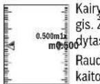
OBJ BUCH-2450-006.book Page 522 Monday, December 18, 2017 12:17 PM


522 | Lietuviskai
Noredami pakeisti matavimo vienetus, paspauskite mygtuk3 [+] arba mygtuk8 [-].
Noredami iseiti is meniu punkto, paspauskite jungimo-isjungimo mygtuka 5 [c]. Matavimo prietaaisa isjungus, pasirinktas nustatmas issaugomas.
Bluetooth® sasaja
OBJ BUCH-2450-006.book Page 523 Monday, December 18, 2017 12:17 PM


Lietuviškai 523
OBJ BUCH-2450-006.book Page 524 Monday, December 18, 2017 12:17 PM


524 Lietuviškai
Central Motors & Equipment LLC
1984:JU
LiwI Lioo-0aogI EJw
a9JwJl
+97165932777:
+97165332269:μsLg
powertools@centralmotors.ae:JgJzJxI Jy
aJlaU UlaU gI acgao
JdJl JalJll Gpo loI (jJl liw EJ
+9671202010:
+9671279029:UuSLa
tech-tools@abualrejal.com: 日 _ 日 ^ 日 gjSJxI
J
Roots Arabia-Jordan
Jua 1j u0uE
aJ137 aJ aLi
jLac 11194
+96265545778:
bosch@rootsjordan.com:gJgJ≤JxI JJ
gJl
JyJyJyJyJyJy
gwhaclloJIaabioJI
13002 - 164:
+96624810844:
+966 24810879:Uu≤Lg
josephkr@aaalmutawa.com:gJ<J|J
Tehini Hana & Co. S.A.R.L.
499-90:
gjglgs
+961 1255211:
service-pt@tehini-hana.com:JgJ<JxI Jy
Jolll
jol jgssal gjj
j0jai53
LJ1J20300
sav.outillage@ma.bosch.com:Jgj<Jx|JuI
Jlac
Malatan Trading & Contracting LLC
131:
jlac aibluw
+968 99886794:
malatanpowertools@malatan.net:gJxI
j
International Construction Solutions W L L
agJ51:JU
jbg
+974 40065458:
+974 4453 8585 :μu≤L
csd@icsdoha.com:gJxI
pIddwXl oJgog nJbjjda
a aai iiai g aai g aai s s s uilw l c n jll do sa jso o gagg jll g b g oc loglaal lcg od aaal p g wll lgc jie jll g
www.bosch-pt.com
pSclw 1 wg aSmu dsswKg goo qg u cgl no ng
gjg jlljoo jd wJg
JUJ JIg aagll g jg jjgl jj
jLggbUulb gI UJluo
jJlJI
Jiuwu
jsslaacll aobioJI
06000 aL
+213(0)982400991/2:
+213(0)34201569:Uu≤Lg
sav@siestal-dz.com:gJx
J
aaii 1
aSoo
+966126971777-311:
+97317704257:UuSLe
h.berjas@eajb.com.sa:gjSJxI
Jai jg.
J20
-0000 -0000
+20222476091-95/+20222478072-73:
+20222478075:UuS19
adelzaki@unimaregypt.com:JgJ<JI J
g
LgJgSiU LgJU LsJw acgao
JaiJI Jb0 EJ
1
+9647901906953:
+97143973851:(L)
bosch@sahbatechnology.com: _ g ≤
Llalllg aJs
:JUSS WU JI I Oc a d s uu
g 10 g 3 2 y g j g g g g g g g g g g g g g g g g g g g g g g g g g g g g g g g g g g g g g g g g g g g g g
-duaio Ujo1
a a 4+ a aaii I wia i I a a i I a i I a i I a i I a i I a aia I aia I aia I aia I aia I aia I aia I aia I aia I aia I aia I aia I
(1g) 1g
jJ. pIgall llll lsslll sLkssb bIa IaIaIbIu IaIy IaIy IaIy IaIy IaIy IaIy IaIy IaIy IaIy IaIy IaIy IaIy IaIy IaIy IaIy IaIy IaIy IaIy IaIy IaIy IaIy IaIy IaIy IaIy IaIy IaI
JusuJusuJusuJusuJJuu
Ic bai I Jn o pialgall jlll 10 w lal sliwX (gwsb
.(aUgUljIomega)LwOgwo)4jj
bJ 1
(Lb) "Error" 1bllg jIq! puuu uuiu uuaa aLac Jla L. 1s sUw uai I ylg luee w dP uuiu uauo ooc
aLac Ug o ybgl dA aLw ayj wIaI Isc gag
baJgJo aIwIwI g jbpIbcIwIcIu .wIg
WLaI Osc pIwIy g ,dIaI O .wIaI Osc ggg
deo Jol y Jl Jl Jl Jn o Wg LAc do sU

ddJg dJUJI
#
JUaJIooac aaijIc laIbga
.1gll no 10jc gI lal I g wlaI osc ubs
g l b i I g o Joo 2. a b g a jb a a a a a a a a a a a a a a a a a
alolglgll
14 14
.1gull oJolS aWsc gI U|Jbill
16 aIgll aiaa 500000000000000000000000000000
aole Udo
aLac 15 juUg 14 uWd aBpJ g
W
0scg g 1c y wll lq .w qll aoc w qll o sc jy j
.uyjksjI gBw gI sao gBw Ic wLJI
wlll lso 0jgo jolgc
.
p dssd sll lal 1 1 1 1 1 1 1 1
plicg1 (Laloll) 17 jUU u g aJg (Laloll) 18 JJU UaJg Jlau
.9gell aabio
wll aee yie 0jgo Jolgc
wLg sic aaijull wIwI Ie abla wIg nn jk
:lagioo o.o. aoliao 2ghw
J 1 J 1 J 1 J 1 J 1 J 1 J 1 J 1 J 1 J 1 J 1 J 1 J 1
.
Bluetooth® auiuI aUgU
J 1
Uuulll JaaLwAaiaa qurbpn c bblteotho o gjo wlaal 0d Uaill (Jw) Bluetooth aaiil algglj jajl all lalll jj
U U U U g | g uuU | uuuu | uuuu | uuuu | uuuu | uuuu | uuuu | uuuu | uuuu | uuuu | uuuu | uuuu | uuuu | uuuu | uuuu | uuuu | uuuu | uuuu | uuuu | uuuu | uuuu | uuuu | uuuu | uuuu | uuuu | uuuu | uuuuu
.1 3
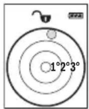
J 1 J 1 J 1 J 1 J 1 J 1 J 1 J 1 J 1 J 1 J 1 J 1 J 1 J 1 J 1 J 1 J 1 J 1 J 1 J 1 J 1 J 1 J 1 J 1 J 1 J 1 J 1 J 1 J 1
.0jS aJy JU LJI UJULOI cJUuJo

0jS1JlUg
LgI I yI g aIoc Jg aIg I g I aIg I n jJ Llogg p
.legio
aJJI aI Jn
. 30 Lc sWl jS
- 5j1JJ aabg jai
IawI g,ajaoa aai j Jr JyJd g Ic Jg
JUJI IaIb g JauJI Uc Jbi loS, Ja aJai ai jaoJI aooJI
Lg
LJdai jai [] 3jjll
.1j1jai jai []8jjl lcb
aaii i 10g jwjbj oJl J p q d gj |j
“0”ddolIwLcIg“0.000"
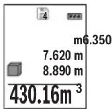
(DgJgJJI) JUa Jc UJgbl Wla (c
.
aI .gblal wlaal abai gai jLwlaal o s gag 1 aI I loo "1" aIwll wiae gai jall ginnll Ugs Jwlaol .Ugb
“X”a glll a glll l c ailll jy wlaal alac pia s y J .“a" a gllg “1" a glll wlg 9 loI e ailljbw d wlaall qj baw
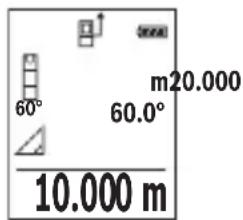
(EoJgJ) JJLJLJU
oio 2gbsu oagao uocnly n jdsaiu w g a.
E 1 J 1 J 1 J 1 J 1 J 1 J 1 J 1 J 1 J 1 J 1 J 1 J 1 J 1 J 1 J 1 J 1 J 1 J 1 J 1 J 1 J 1 J 1 J 1 J 1 J 1 J 1 J 1 J 1 J 1 J 1 J 1 J 1 J 1 J
UJdlaLwO wUg j
wIaIaaJb.1gblwIg sic Jll gLoH oJal aIwO wIy b 9 .Joo jull Jb. wIaIlaoJ gJlJIbWl I
.1g 1s g 1s 1s 1s 1s 1s 1s 1s 1s 1s 1s
10
aI I Jg jbi. dgc g llogig pJw P wll qil sO 0Lc kawalqall g, jol 0ag Jow aill qill aii
Lg9g
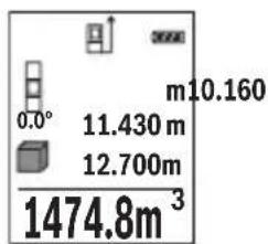
uuauee uuuu
wlaqIgSawg wlaqJswbWwlaqJw g. aIoo
JL 10000000000000000000000000000000000000000000000000000
L 1
a a a a a a a a a a a a a a a a a a a a a a a a a a a a a a a a a a a a a a a a a a
.
(BgJglj) JUoEaJlWla (a
.
J 1 J 1 J 1 J 1 J 1 J 1 J 1 J 1 J 1 J 1 J 1 J 1 J 1 J 1 J 1 J 1 J 1 J 1 J 1 J 1 J 1 J 1 J 1 J 1 J 1 J 1 J 1 J 1 J 1 J 1 J 1 J 1 J 1 J 1 J
aWU|cL
JjI Jc bcl lgl .Jn m u k w y jol o dag o1 Jy W /uJIbll aaw Ic blaull 20 Ug 20 gdae jol o dag o1 plic | p
wJlI 1g
UgBg
Hgblwloj jai
[2 wll jj l c g aolg juU g
wlaal aq jbj.2 wlaal jj lc oag alg bdsl wlaal
. l l |
aag jgj. jI wI g 1J Jn nn oI gS dJ I gbl J S .Igogg aai I gg g aWuI JowI aWLa
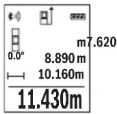
jauu u
ai lalei iil wlll jy d ic d qull auiu y uall o dc k n jn j 1j 0,5 Jd lalwlaa aagaa .laI IJI IJ T JI eSawg Uggeauu
1-1juaJU
[2 wll jj l c o g aol juUg
.aaI I JwUgGJALI JI JI JI JI JI JI JI JI
12 wluall jj 1c g aalg bau all jn cikay j.awll lawl ayall wluall aagj jaiwll wluall jj 1c lssbail. g g g yllg gllwluall aag .d jy joiuall wluall i [2 wluall .loggi5
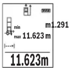
LlI
LalwJUWg
wJl.1g2I wJg2I wJg2I wJg2I wJg2I wJg2I wJg2I wJg2I wJg2I wJg2I wJg2I wJg2I wJg2I wJg2I wJg2I wJg2I wJg2I wJg2I wJg2I wJg2I wJg2I w
L
wJJI aJoc
wlaagabg.11gblwlaagabg g wlaalldc ngsjlll [+] jll psswbyagcglwlaalldaagbgtjdl.[Func]7 jllglcbpsjgl wlaalld aagbg lssy (538aaos:“wlaalldg”jbl)[-]8jjlg3
. [ ]2 [Func]7jj1p1sawu
wJlqlllslIgssuWsuIyIaIqIaIqIaIqIaIqIaIqIaIqIaIqIaIqIaIqIaIqIaIqIaIqIaIqIaIqIaIqIaIqIaIqIaIqIaIqIaIqIaIqIaIqIaIqIaIqIaIqIaI
(bai jll lss w (c) aagjll sylal abai yw al o d g [0]5 alg jll j qjub n c wll osc jll w all g :abalo
jlll l2 wlljjc ggl
Eab] 2 wll jwll JJ Jc oag alg l bai
A
Jus Jc g juI e
X.aaalllgglgagalljolallgsLgALIaALIe 2. g uuun uuauuauuauuauuauuuuauuauuauuauuauuauuauuauuauuauuauuauuauuauuauuauuuuuuuuuuuuuuuuuuuuuuuuuuuuuuuuuuuuuuuuuuuuuuuuuuuuuuuuuuuuuuuuuuuuuuuuuuuuuuuuuuuuuuuuuuuuuuuuuuuuuuuuuuuuuuuuuuuuuuuuuuuuuuuuuuuuuuuuuuuuuuuuuuuuuuuuuuuuuuuuuuuuuuuuuuuuuuuuuuuuuUU
Jg Jg Jg g Jg Jg Jg Jg Jg Jg Jg Jg Jg Jg Jg Jg Jg Jg Jg Jg Jg Jg Jg Jg Jg Jg Jg Jg Jg Jg Jg Jg Jg Jg Jg Jg Jg Jg Jg Jg Jg Jg Jg Jg Jg Jg Jg Jg Jg Jg Jg Jg Jg Jg J
Labg
.2 wIJIJJ Jc 0gJjUlg WJIJI Isc JwJrJ - JJc 0gJjUlg WJIJI Isc JwJrJ .5
-
- 4
Uulll 9
UJUJI OJAA Ubc 10
Julwuaill 11
jUU-uuai 12
4/1 1 1111 13
JuaWzI aWsc 14
jU| 150 15
aLg aua 16
jJ11 jw aag 17
*jUll 18
*gll 19
LgI I gI I gI I gI I gI I
(juai )jui jolic
Bluetooth aL a
UJWlI LwJpB pJ, Uo Bluetooth
JLJX1 Lwj pJ Joo Bluetooth


wulai slwi 1gswb
aJbJI Jc
wUJgJbWd
auiu bwe
wlaolg f
JaiagjUg g
aUulbμw h
aawwI bduI g
uJI
UJlIJI IJI JI JI JI
oo 1
wJJI
12 1,2 pSpo 1aai aaiaaal wlaal lao s
1.5 UUul
JJJUu
UulJd
Bluetooth® 4.0
Bluetooth®
(GLow Energy g Classic)
山 2402-2
blgluo 2,5
JwJ oJg G
a aal ool 100000000000000000000000000000000000000000000000000000000000000000000000000000
(B)+45℃-10C no jjg g aol 010g 000000000000000000000000000000000000000000
J 01 90g0s paii (C
25^ 1
+40°C jaaal l wlll aag ygsswlll 1j J (E
LJ 2 (a a) Low Energy Bluetooth aia jgjll aill G acgao Bluetooth ojei p 1.
Jooo jC Bluetooth (H
Jgssal 1j
a a o gagall wlll o gwJ l jgaoal 1j
abbsIgWJl aWuJ1
[△]wuljj2
[+]jIJJj3
1iWgI gIj4
[0]labg uusuul eoo 5
Bluetooth 6
[Func] 1g7
[-]u#ljj8
Uc543
| (A) mo 1,5± | (Q) qd(j) | |
| (B) mo 3,0± | (R) (A) w.l.l. (B) (C) qd(j) | |
| (S) m.l.l. (D) qd(j) | ||
| (T) m.l.l. (E) qd(j) | ||
| (U) m.l.l. (V) qd(j) | ||
| (W) m.l.l. (X) qd(j) | ||
| (XI) m.l.l. (XI) qd(j) | ||
| (Y) m.l.l. (Y) qd(j) | ||
| (Z) m.l.l. (Z) qd(j) | ||
| (AB) m.l.l. (AB) qd(j) | ||
| (C) D) | (D) m.l.l. (D) qd(j) | |
| (E) | (E) m.l.l. (E) qd(j) | |
| (F) | (F) m.l.l. (F) qd(j) | |
| (G) | (G) m.l.l. (G) qd(j) | |
| (H) | (H) m.l.l. (H) qd(j) | |
| (I) | (I) m.l.l. (I) qd(j) | |
| (J) | (J) m.l.l. (J) qd(j) | |
| (K) | (K) m.l.l. (K) qd(j) | |
| (L) | (L) m.l.l. (L) qd(j) | |
| (M) | (M) m.l.l. (M) qd(j) | |
| (N) | (N) m.l.l. (N) qd(j) | |
| (O) | (O) m.l.l. (O) qd(j) | |
| (P) | (P) m.l.l. (P) qd(j) | |
| (Q) | (Q) m.l.l. (Q) qd(j) | |
| (R) | (R) m.l.l. (R) qd(j) | |
| (S) | (S) m.l.l. (S) qd(j) | |
| (T) | (T) m.l.l. (T) qd(j) | |
| (U) | (U) m.l.l. (U) qd(j) | |
| (V) | (V) m.l.l. (V) qd(j) | |
| (W) | (W) m.l.l. (W) qd(j) | |
| (X) | (X) m.l.l. (X) qd(j) | |
| (Y) | (Y) m.l.l. (Y) qd(j) | |
| (Z) | (Z) m.l.l. (Z) qd(j) | |
| (AB) | (AB) m.l.l. (AB) qd(j) | |
| (AC) | (AC) m.l.l. (AC) qd(j) | |
| (AD) | (AD) m.l.l. (AD) qd(j) | |
| (EA) | (EA) m.l.l. (EA) qd(j) | |
| (FA) | (FA) m.l.l. (FA) qd(j) | |
| (GA) | (GA) m.l.l. (GA) qd(j) | |
| (HA) | (HA) m.l.l. (HA) qd(j) | |
| (IA) | (IA) m.l.l. (IA) qd(j) | |
| (JA) | (JA) m.l.l. (JA) qd(j) | |
| (KA) | (KA) m.l.l. (KA) qd(j) | |
| (LA) | (LA) m.l.l. (LA) qd(j) | |
| (MA) | (MA) m.l.l. (MA) qd(j) | |
| (NA) | (NA) m.l.l. (NA) qd(j) | |
| (OA) | (OA) m.l.l. (OA) qd(j) | |
| (PA) | (PA) m.l.l. (PA) qd(j) | |
| (QA) | (QA) m.l.l. (QA) qd(j) | |
| (RA) | (RA) m.l.l. (RA) qd(j) | |
| (SA) | (SA) m.l.l. (SA) qd(j) | |
| (TA) | (TA) m.l.l. (TA) qd(j) | |
| (UA) | (UA) m.l.l. (UA) qd(j) | |
| (VA) | (VA) m.l.l. (VA) qd(j) | |
| (WA) | (WA) m.l.l. (WA) qd(j) | |
| (XA) | (XA) m.l.l. (XA) qd(j) | |
| (YA) | (YA) m.l.l. (YA) qd(j) | |
| (ZA) | (ZA) m.l.l. (ZA) qd(j) | |
| (UA) | (UA) m.l.l. (UA) qd(j) | |
| (WA) | (WA) m.l.l. (WA) qd(j) | |
| (XA) | (XA) m.l.l. (XA) qd(j) | |
| (YA) | (YA) m.l.l. (YA) qd(j) | |
| (ZA) | (ZA) m.l.l. (ZA) qd(j) | |
| (UA)(WA) | (UA)(WA) qd(j) | |
| (WA)(WA) | (WA)(WA) qd(j) | |
| (XA)(WA) | (XA)(WA) qd(j) | |
| (YA)(WA) | (YA)(WA) qd(j) | |
| (ZA)(WA) | (ZA)(WA) qd(j) | |
| (UA)(WA) | (UA)(WA) qd(j) | |
| (WA)(WA) | (WA)(WA) qd(j) | |
| (XA)(WA) | (XA)(WA) qd(j) | |
| (YA)(WA) | (YA)(WA) qd(j) | |
| (ZA)(WA) | (ZA)(WA) qd(j) (ZA)(WA) qd(j) | |
| (UA)(WA) | (UA)(WA) qd(j) | |
| (WA)(WA) | (WA)(WA) qd(j) | |
| (XA)(WA) | (XA)(WA) qd(j) | |
| (YA)(WA) | (YA)(WA) qd(j) | |
| (ZA)(WA) | (ZA)(WA) (ZA)(WA) qd(j) | |
| (UA)(WA) | (UA)(WA) qd(j) | |
| (WA)(WA) | (WA)(WA) qd(j) | |
| (XA)(WA) | (XA)(WA) qd(j) | |
| (YA)(WA) | (YA)(WA) qd(j) | |
| (ZA)(WA) | (ZA)(wa) qd(j) | |
| (UA)(WA) | (UA)(WA) qd(j) | |
| (WA)(WA) | (WA)(WA) qd(j) | |
| (XA)(WA) | (XA)(WA) qd(j) | |
| (YA)(WA) | (YA)(WA) qd(j) | |
| (ZA)(WA) | (ZA)(WA) qd(j)\n | |
| (UA)(WA) | (UA)(WA) qd(j)\n | |
| (WA)(WA) | (WA)(WA) qd(j)\n | |
| (XA)(WA) | (XA)(WA) qd(j)\n | |
| (YA)(WA) | (YA)(WA) qd(j)\n | |
| (ZA)(WA) | (ZA)(WA) qd(j)\n | |
| (UA)(WA) | (UA)(WA) qd(j)\n | |
| (WA)(WA) | (WA)(WA) qd(j)\n | |
| (XA)(WA) | (XA)(WA) qd(j)\n | |
| (YA)(WA) | (YA)(WA) qd(j)\ns\n | |
| (ZA)(WA) | (ZA)(WA) qd(j)\ns\n | |
| (UA)(WA) | (UA)(WA) qd(j)\ns\n | |
| (WA)(WA) | (WA)(WA) qd(j)\ns\n | |
| (XA)(WA) | (XA)(WA) qd(j)\ns\n | |
| (YA)(WA) | (YA)(WA) qd(j)\ns\n | |
| (ZA)(WA) | (ZA)(WA) qd(j)\ns\n | |
| (UA)(WA) | (UA)(WA) qd(j)\ns\n | |
| (WA)(WA) | (WA)(WA) qd(j)\ns\n | |
| (XA)(WA) | (XA)(WA)q d(j)\n | |
| (YA)(WA) | (YA)(WA)q d(j)\n | |
| (ZA)(WA) | (ZA)(WA)q d(j)\n | |
| (UA)(WA) | (UA)(WA)q d(j)\n | |
| (WA)(WA) | (WA)(WA)q d(j)\n | |
| (XA)(WA) | (XA)(WA)q d(j)\n | |
| (YA)(WA) | (YA)(WA)q d(j)\n | |
| (ZA)(WA) | (ZA)(WA)q d(j)\n | |
| (UA)(WA) | (UA)(WA)q d(j)\n | |
| (WA)(WA) | (WA)(WA)q d(j)\ns\n | |
| (XA)(WA) | (XA)(WA)q d(j)\ns\n | |
| (YA)(WA) | (YA)(WA)q d(j)\ns\n | |
| (ZA)(WA) | (ZA)(WA)q d(j)\ns\n | |
| (UA)(WA) | (UA)(WA)q d(j)\ns\n | |
| (WA)(WA) | (WA)(WA)q d(j)\ns\n | |
| (XA)(WA) | (XA)(WA)q d(j)\ns\n | |
| (YA)(WA) | (YA)(WA)q d(j)\ns\n | |
| (ZA)(WA) | (ZA)(WA)q d(j)\ns\n | |
| (UA)(WA) | (UA)(WA) q d(j)\ns\n | |
| (WA)(WA) | (WA)(WA) q d(j)\ns\n | |
| (XA)(WA) | (XA)(WA) q d(j)\ns\n | |
| (YA)(WA) | (YA)(WA) q d(j)\ns\n | |
| (ZA)(WA) | (ZA)(WA) q d(j)\ns\n | |
| (UA)(WA) | (UA)(WA) q d(j)\ns\n | |
| (WA)(WA) | (WA)(WA) q d(j)\ns\n | |
| (XA)(WA) | (XA)(WA) q d(j)\ns\n | |
| (YA)(WA) | (YA)(WA) q d(j)\ns\n | |
| (ZA)(WA) | (YA)(WA) q d(j)\ns\n | |
| (UA)(WA) | (UA)(WA) q d(j)\ns\n | |
| (WA)(WA) | (WA)(WA) q d(j)\ns\n | |
| (XA)(WA) | (XA)(WA) q d(j)\ns\n | |
| (YA)(WA) | (YA)(WA) q d(j)\ns\n | |
| (ZAI) | (ZAI) q d(j)\ns\n |
oojloI Ic abfaal lJ Jnog. bao aolJlJgBgJloswug .uJqJI
gogoo jgsjllwgl aawu Joa
<ulglinLjS
4 0scgJgL
JgJolpIaWJI JgUJbAaJol
g g 1111111111111111111111
.

aawuUdLc
JjUg
A
山 jlljglc
g jlll a g j lj b j s j. aolg o ljbsi jlll a g j o ljb pss X .jjlll cclw! no y Lqikg jjlll elw a g j aikso! nss
Jg j g a a a a a a a a a a a a a a a a a a a a a a a a a a a a a a a a a a a a a a a
juiufo 0gglg g gjI u
n g u g w, t a J l a w c g w y w g j I w y ta d s j f J 12 b g o j J d cllbl g gla .d wg g w y c algo g k d cdo g 3u la j g j o mol i c w j d ilgio I caleo g k
www.bosch-pt.com
:gl a slal gac slgus lba
Jgss g doli jn s qpsu yjss 1slaa u 2012/19/EU 2006/66/EC
.ubgao 5jdua dg 10 g
J 15 J 15 J 15 J 15 J 15 J 15 J 15 J 15 J 15 J 15 J 15 J 15 J 15 J 15 J 15 J 15 J 15 J 15 J 15 J 15 J 15 J 15 J 15 J 15 J 15 J 15
su lau dau loo
(ulss)duu w u JSLogai
jIjI. CwI pJg g JgB jolg 5I yogdy dJd wjl nnS oJaiWl
J 13 1/4> ojj 1 s
o|j|j|j. 1gLc Lgaoa dU dU SgJ g 19 aU dU
.5s pss yjw jgsj lla daa o s g j j lgo a dawg j s
4doJjJlqjI dUdUwUgUjSsUJU
.1sS pBb (cwwogjjgjo baw)
Ua pU
Jai dao J 《Error》gLpa yjol jol pao jol pao jol jol
.10gjj
oJusI jgS oJdil gS JgS oJdil JjI CooIe S bag jyogadaw, sui c uic djiis .si J.ogw o wgola oJdil jjI g D wu jw jai I yalaj l k yi
Bosch

uugw9cIjo
oLswJ jg g JpJ 1
.1J 0j jai oJgaw J gui jil jI
.1j g abg c 1a lo u w lg u j d l j y ojl jl
JjI jI .dS o Jiaawl gbpog pji Iaaa s jI 1gJn Js y
.
J. 1 J. 1 J. 1 J. 1 J. 1 J. 1 J. 1 J. 1 J. 1 J. 1 J. 1 J. 1 J. 1 J. 1 J. 1 J. 1 J. 1 J. 1 J. 1 J. 1 J. 1 J. 1 J. 1 J. 1 J. 1 J. 1
Gluu 0j1sll jis
:J 1 J g j g j 1 J g g oj d j j 1 J g d J g oJ 1 J g 1 J g 1 J g 1 J g 1 J g 1 J g 1 J g 1 J g 1 J g 1 J g 1 J g 1 J g 1 J g 1 J g 1 J g 1 J g 1 J g 1 J g 1 J g 1 J g 1 J g 1 J g 1 J g 1 J g 1 J g 1 Jg 1 Jg 1 Jg 1 Jg 1 Jg 1 Jg 1 Jg 1 Jg 1 Jg 1 Jg 1 Jg 1 Jg 1 Jg 1 Jg 1 Jg 1
.0jol
Bosch 8QR-Code
Jy j J 10000000000000000000000000000000000000000000000000000000000000
JLw oKsw S g J Cbbl JLaBn Bleeth 8uJ Lg
J 6 Bluetooth aas Bluetooth J 6 J 6Bluetooth aas ojug Bluetooth J 6 J 6 J 6 J 6 J 6 J 6 J 6 J 6 J 6 J 6 J 6 J 6 J 6 J 6 J 6 J 6 J 6 J 6 J 6 J 6 J 6 J 6 J 6 J 6 J 6 J 6 J 6 J 6 J 6 J 6 J 6 J 6 J 6 J 6
Iol doli, lall Iaill Jg W g Jw o Kss S JkLac p a Jt j Egi c w n 10doljnn .siu yo gogos Bosch (Apps) sJls.
S 0jdl jbjg jw oosb Bosch (App) aolj g jl w jbl, clll l jsl jnl swh s jgs w g jrl g. .dik bll jjw oosk d jn jj jg o 01 jnl jnl jnl (h) cllc wj j (a) jgl bjrl g bljrl
Bluetooth
J 6 Bluetooth aoss Bluetooth J 8 6Bluetooth
Joc sl Jlaai
a 8 aQr-Code
4JSLg
.
Lg g lbl
.15 14 12 12 12 12 12 12 12 12 12 12 12
550|LwJ
J 100
143.45m2
[ ]2 1 J
J J J J J J J J J J J J J J J J J J J J J J J J J J J J J J J J J J J J J J J J J J J J J J J J J J J J J J J J J J J J J
oJjI JI JI JI JI JI JI
L5 5 5 5 5 5 5 5 5 5 5 5 5 5 5 5 5 5 5 5 5 5 5 5 5 5 5 5 5 5 5 5 5 5 5 5 5 5 5 5
g jolal dalg oog .w1 (j) 《m》 g jolal dalg ag jolgl jy j. j. j. j. j. j. j. j. j. j. j. j. j. j. j. j. j. j. j. j. j. j. j. j. j. j. j. j. j. j. j. j. j. j. j. j. j. j. j. j. j. j. j. j. j. j. j. j. j. j. j 8 aks [+] 3 aos J5 wj-wwgola dsk gjjjjjj
Bluetooth
Ig kswu w y Ia Jlai
Bw gJr jclal b d s W y jy Bluteoth pssw y Bj 1j J
(1) (1) 100) Bluetooth'll Jd J
.
J
J
J
J
J
J
J
J
J
J
J
J
J
J
J
J
J
J
J
J
J
J
J
J
J
J
J
J
J
J
J
J
J
J
J
J
J
J
J
J
J
J
J
J
J
J
J
J
J
J
J
J
J
J
J
J
J
J
J
J
J
J
J
J
J
J
J
J
J
J
J
J
J
J
J
J
J
J
J
J
J
J
.1uI I J 1000 u Gb g
Jg j 0j1s i d aai y Cwsi ojl jbjd s i S g S jil sio g j j j j j j j j j j j j j j j j j j j j j j j j j j j j j j j j j j j j j j j j j j j j j j j j j j j j j j j j j j j
JXg Jggo 100o jol s ojl u j 100 g 1o0o jol s0j ldo e djj b w .d0d0jol jdo o0j0b w Jd0
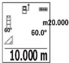
(Egawd gwegj)Jggsbaw 0jdlogai
bui j sJSLac pww g J Ss wu w u wu wu wu wu wu wu wu wu wu wu wu wu wu wu wu wu wu wu wu wu wu wu wu wu wu wu wu wu wu wu wu wu wu wu wu wu wu wu wu wu wu wu wu wu wu wu wu wu wu wu wuuw u u u u u u u u u u u u u u u u u u u u u u u u u u u u u u u u u u u u u u u u u u u
Bluetooth.
. 山 山 山 山 山 山 山 山 山 SPP 1uww Lgww Lgwl
Bluetooth(H
11 1jolaw jsljjgds jss
wUoWu(UsoS)
ω|561
i
U


- GLM 50 C Professional
- BOSCH
- 2
- Deutsch
- Sicherheitshinweise
- 14Deutsch
- Deutsch | 15
- | Deutsch
- | Deutsch
- Deutsch|21
- | Deutsch
- Deutsch|23
- Deutsch|25
- | Deutsch
- | English
- English | 29
- Product Description and Specifications
- Intended Use
- Technical Data
- English | 31
- Product Features
- Operation
- Initial Operation
- Switching On and Off
- Measuring Procedure
- b) Double indirect Height Measurement (see figure C)
- c) Indirect Length Measurement (see figure D)
- Wall Surface Measurement (see figure E)
- | English
- Stake out Function (see figure F)
- Gradient Measurement/Digital Spirit Level
- English | 39
- Memory Functions
- Memory Value Display
- Deleting the Memory
- Adding/Subtracting Values
- English | 41
- General Information
- Working with the Tripod (Accessory)
- Error Message
- Maintenance and Service
- Maintenance and Cleaning
- After-sales Service and Application Service
- www.bosch-pt.com
- Republic of South Africa
- Customer service
- Gauteng - BSC Service Centre
- KZN - BSC Service Centre
- Western Cape - BSC Service Centre
- Bosch Headquarters
- Disposal
- | Français
- Only for EC countries:
- Great Britain
- Français
- | Français
- | Français
- | Français
- Processus de mesure
- | Français
- | Français
- | Français
- Francais|61
- 64]Français
- France
- 66|Espanol
- Espanol 69
- | Espanol
- a) Medicion indirecta de alta (ver figura B)
- | Espanol
- Restar valores
- 80|Espanol
- | Espanol
- Portugues|89
- | Português
- a) Medico de alterua indireta (ver a figura B)
- | Portugues
- Medicão da superficie da parede (veja figura E)
- | Português
- | Portugués
- Portugues|101
- Italiano
- Norme di sicurezza
- Italiano | 115
- 120|Italiano
- | Netherlands
- 130|Nederlandsl
- Menu „Basisinstallingen"
- 132|Nederlandsls
- Nederlands
- 136|Nederlandds
- Nederlands | 137
- 138|Nederland
- Dansk|141
- Montering
- 146|Dansk
- Displaybelysning
- Mälefunktioner
- Laengdemåling
- Konstant måling
- b) Dobbelt indirekte hjojdemåling (se Fig. C)
- | Dansk
- Vardier adderes/subtraheres
- Vardier adderes
- Deaktivering at Bluetooth®-interface
- Dansk
- | Svenska
- | Svenska
- Norsk
- Avfallshantering
- Norsk|173
- Formalsmessig bruk
- Illustrerte komponenter
- Norsk|177
- 178|Norsk
- Måling
- Norsk|183
- Norsk
- Mittaustoimenpide
- | Suomi
- 206|EAAyVikd
- Pepiypapn Tou npoiovtoc kal nct loxoc tou
- Xpion oupwa va Tov npoopio
- Texvka xapaktnioku
- 208|EAAyVikd
- 210|EAAynvka
- Aetroupyia
- Oeog aeIetroupyla
- OeogaeAeIoupyiaKekocAeIoupyiac
- Auaibikiaoa metpononc
- Emloy ennebou avapopac (Bene eikova A)
- Mevou(Baoukερμioε)
- 214|EAAyVikd
- a) Emuon perton uwv (Baeceiova B)
- 14.142m
- b) DuaH emuon pertpon uupov (Bale Ekovo C)
- c) Emuon mepon nukov (Blenc ekova D)
- Metponen emupaveov toixov (Baeene eikova E)
- Aetroupyia opioeTeiOnc (Bene eKova F)
- EMnviKa1217
- Aaypaipn (23nmao) nnc mnnns
- 218|EAAyVikd
- ApaipaeonTuow
- Diaypaipnmuovheptnonc
- Alambda'povadacheptponnc
- Oupa bietaaphc Bluetooth
- Metapopd e aae ouakeute
- Evpyonolnon TcOpuac dietaPc Bluteoth yia nIeapopa 6ebouevov ae Ia KnuTn teuku oukeun
- Anepepyooinan nC 8upac biuaqic Bluetooth
- YnobsieEeepyaoic
- Tevkoc unofoelEe
- Emipoeic otyn nepioxh metpon
- 220|EAAynuKd
- Embpaooeo anotaleogmuetpnan
- Eeeyoc akipieac kai nct metponc anooraon
- Epyaiae to tpinobo (eiuko eapntma)
- | Türkçe
- Isletme
- Calistirma
- Endirekt uzaklik ölcümü
- | Türkçe
- c) Endirekt uzunluk ölcümü (Bakirüz: Şekil D)
- | Türkçe
- Bellek degeri gostergesi
- | Türkçe
- Montaž
- | Polski
- | Polski
- Pomiar ciagty
- Interfejs Bluetooth®
- | Polski
- Montáz
- Nasazeni/vymena baterii
- | Cesky
- Osvétlení displeje
- Méricifunkce
- Merené délyk
- | Cesky
- Cesky|273
- | Cesky
- | Slovensky
- | Slovensky
- Vyobrazene componenty
- | Slovensky
- Použivanie
- Uvedenie do prevadzky
- Zapinanie/vypinanie
- Slovensky | 287
- | Slovensky
- Spocitavanie hodnot
- | Slovensky
- | Slovensky
- Práca so stativom (Prisluşestvo)
- 298Magyar
- 302Magyar
- Terfogatmeres
- 304Magyar
- | Magyar
- Magyar|307
- XpaHeHne
- | Pycckn
- TpaHcnpToPbOvKa
- Yka3aHHNo 6e30nacHocTH
- Pycckn | 313
- OnncHne npoDyKta n ycnyr
- PpIMeHHeHn No Ha3HaueHHIO
- | Pycckn
- 1306paXeHHbIe coCTaBHbIe qACTH
- Hdikatopby(Bb6op)
- C6opka
- YctahOBka/3aMeHa 6aTapeek
- | Pycckn
- Pa60Ta c HhctpymehtOM
- 3Kcnnyataaun
- | Pycckn
- MeHIO《OChOBbIe HAcTpoiKn》
- Iopcbetka dncnne
- Pexhmbln3mpehenn
- N3mepeHne nnHHbI
- IpoJOnKHTenbHoe H3MepeHHe
- H3mepeHne nloaann
- H3MepeHHe 06bema
- KocbeHHoe H3MepeHne pacCToHHN
- | Pycckn
- a)KocBeHHoe H3MepeHHe BbICToBc (cm.phc.B)
- b)Дбоиhoe KocbeHnoe H3MepeHne BbcotblcM.pnc.C)
- | Pycckn
- PexHM pa3MeTKn (cm. pnc.F)
- H3mepeHne yrna haknoHa/LnΦpOBoB Batepnap
- Pycckn|325
- Функшпamathn
- OTo6paXeHne coXpaHeHHbIX 3HaueHm
- CTmpaHne nAMATN
- Cnoxhen/ByiHTaHne 3haeHHN
- | Pycckn
- CloxKeHne 3naueHH
- OTHMMaHHe 3NaueHHN
- YdaneHHe H3MepeHHbIX 3HaueHn
- CmeHa eHHnCbH3MepeHnA
- UHTeppeic Bluetooth
- Ipeepa daanbbix na npyhe npn60pb
- Boene noopobha Hnphiopmaunna HaxoHntca Ha ctpaHnue npoykta Bosch, cm.QR-KoD,ctp.8.
- AkhbaaHHTepceca Bluetooth- dna nepeaun daHHbIX Ha Mo6HbHoe oKeHneHoe yctpoiCTBO
- DeakthBaunHHTeppeCa Bluteoth
- IINPEeJaH DaHbIX HaMo6HbHoe Oko
- 8
- 328|Pycckn
- Yka3aHHI IO pHmHeHIO
- 06zne yka3aHHN
- Фaktobpbl, BnnaIOUne Ha dHaNa3OH H3MepeHn
- ФaktobpblBnHIOUneHape3yNbTaH3MepeHHN
- PpOBePKaTOHOCnKan6pOBKa pN H3MepeHHyHa KaHNoHa (cm.pHC.G)
- IpoBepka ToUHOCTN 3MepeHn paCtOHHN
- Pa6oTa co wTaTHBOM (nPHHaNExKHOCTH)
- Coo6ueHne 06 oon6ke
- YkpaHcbKa
- Bka3iBkn 3Texhikn 6e3neKn
- | Ykpaɪhcbka
- Pn3NaeHHa
- Texhi dahi
- 3o6paXeHI KOMnOHeHTH
- BMnKaHH/HBMnKaHH
- He cnpmaOByte na3epHn npomIHb hAIOe i TBapHn i He dmbitbcy na3epHn npomIHb, BKNIOaOHn 3 BenKOi BiCTani.
- | Ykpaɪhcbka
- Bn6ip 6a3oBoI nnoouHH (DnB. Man. A)
- Meho《OchOBHI HAcTpOiKN》
- PiicbivBaHnHaucnne
- BmipioBaIbHi fynKuII
- BmipioBaHHdoBXHH
- TpBane BmipobHn
- Bmipobanha nnoi
- BmipobaHaHa 06'Emy
- | YkpaIhcbKa
- Hempame BmipkoBaHH BiDcTahi
- a) Henpame BHMipOBaHHBHCOTN (Hb.MaB.B)
- b)IodBimHe Hnpe BmipHOBaHH BHCOTH (IMB.MAN.C)
- c) Henpme BmipobAHn DOBxHH (INB. Man.D)
- BmipobhaHnnoi CTIN (mB. Man. E)
- | Ykpaɪhcbka
- PexHM po3mITKn (DNB. Man. F)
- BmipobAHHa KyTb Haxnly/UnpObn Batepna
- Функii nam'rti
- Biodo6paaxeHH36epexeHHx3HaueHb
- CtpanHHBmicty na'nti
- Iodabahn/HbjHimAHn3hauehb
- Ddaabannn3nauehb
- Bidimahnhaueh6
- CTnpaHHBnMipHnx3HaueHb
- 3mHaOdHHuBmipoBaHHa
- Intepfchc Bluetooth
- Ipepaa daHnHa iHni npnai
- Akhbaia InTepeCy Bluetooth® dna nepepaHHaMo6InbHn KInceBn npctpi
- DaekthBaiai InTepeHcy Bluteoth
- | Ykpaɪhcbka
- Bkaizbkn 0doo po6oTn
- 3arabhi Bka3iBKn
- ΦaKToH BnMbBy Ha diana3OH BmIpIOBaHH
- Φaktopn BnNBy Ha pe3ynbTaB BMIpObaHH
- IpeBipKaToHocTi Ta Kani6pyBaHHaN BnMIpHOBAHHaYta Haxnny (nB.Ma. G)
- Ipebipka Touhocti BmipboBaHH BiDcTaHi
- Pobota 3i WtataHbOM (npHnad)
- Tobidomnenna pno nOmnkn
- Texhihe 06cnyrobybaHHia cepbic
- Texhiueo6cnyrobybannioounneHHN
- Cepbic HanaHnKaoncynbTauioBnKOpncTAnHH npOyKu
- Ka3akwa
- Ohimdi nai danany Mep3imi
- Kb3MeTKeH Neme NaIaAnaHyBbHk KaTeNikTepi MeH icTeH bHy ce6ntepinH ti3imi
- TexHnKaIbIK Kbi3MeT KepeCy Typi MeH Xniniri
- CaKray
- TacbImaJay
- Kayinci3ik HycKaynapbl
- |KazaaKuia
- Θhim XΘe Kbl3MeT CnnaTTaMaCbI
- TaFaiBIndany 6oBbHwa KOnDaHy
- Kopctkiw 3neMeHTeP (taHaMaIbI)
- XnHay
- BaTapeaIapIbIcany/aImaTcbIpy
- | Ka3aKaIIa
- PaiDanaHy
- Painanahya eHdipy
- Kocy/ewipy
- "Heriari napametnpep" M3pi
- Диспл徳жарыгbl
- Oniwey yhknnnapbl
- ¥3bIHdbkTb onney
- Y3dikci enwey
- Ka3aKaIIa
- a) KaHama 6nIKrKi 0neuey (BCypetIH KapaHb3)
- b) Koc kama 6niktikti enwey (C cypetih Kapa h3)
- c) KaHama y3bHbIbKbI bIe Hwey (D cypetIH KapaHbI3)
- Ka6bipra aydaanbH enwey (E cypetin KapaHb3)
- Benriney fyHKuncbI (F cypetIH KapaBbI3)
- Ka3aKaIIa
- KoBeydi onwey/CaHdbik ypoBeh
- CaKayfynHKunnaIapbl
- CaKaTaJaFaH MAn KepcTeKlWi
- CaKtaftbIuTafBblEwipy
- Mændepj Kocy/any
- MhandepdiKocy
- Mankdepni any
- Onwey hataxeneepin xio
- Onwey 6ipnirin anMaTbpy
- Bluetooth® nHTepfchci
- Bluetooth® yawbirbiH eWipy
- Paindanahy HycKaynapbi
- | Ka3aKaIIa
- TaraHMeH naIaIaIaNy (kepeK-kaPaKaTap)
- Katenik xa6apbl
- TexHHKaIbIK Kytim XKHe Kbl3MeT
- Kb3MeT Kcpcty KHe Ta3anay
- TybHybIka Kb3MeT KepcTey XeHne NaiDanahy Kehectepi
- Ka3aKCTah
- | Romaná
- Procesul de māsurare
- Stergerea valorii masurate
- Schimbarea unitati de masura
- | Romaná
- Onncahne Ha npodykta H Bb3MOxHocHTe My
- IpeHa3NaYeHHe Na ypeHa
- BbIrapckn | 391
- H306pa3eHH enemeHTN
- H3o6pa3eHH enemeHTN
- 392|BbIrapckn
- Toka3BaHH eneMeHTH (n36Op)
- MOnTnpaHe
- TocTabaHe/cmHaHa 6atePnHtE
- Pa60a cypepa
- Iyckane Bekcnoataa
- BkIIOUBAHn H3KIOUBAH
- 394|Былгарский
- №MepBaHe
- H36op Ha otnpaBHa paBHHHa (BHXTe fHr. A)
- MeHNO,OCHOBNHaCTPOINKn
- OcbetneHHe Ha dncnne
- PexmmHaH3MepBaHe
- №MepBaHe Ha bNnHa
- HnpeKbchato N3MepBaHe
- H3mePbaHe Ha nioou
- №3mepBaHe Ha 06eM
- HnHpeKTHo H3MePbAe Ha DblxHHa
- a) INHnpeKTHo N3MepBaHe Na HBCOuHa (BNXTe pHyp a B)
- b)Довин Идпөртхо Имөрbaе Ha Bнсоунha (BnxTeФг.С)
- c) NmnpkeTHo N3mepBaHe Na dbIaKHa (BnXte pHr.D)
- 398|BbIgapckn
- OnpeenHe Ha nnoa Hn CTeHn (BnXte pHr. E)
- IpehaheHaabJHHa(BHKeFmR.F)
- H3mepbaHe Ha haknoh/UnΦpOB HnBeHHp
- 3anametbaheHaH3MepeHHCTOHOCTH
- 3anaMeTeHN cToHOCTH
- 400|BbIrapckn
- H3tpnBaHe Ha cbIbpxKaHMeTo Ha nMaMeTTa
- Cb6HpaHe/H3BaXJaHe Ha cToHocTH
- Cb6hpaHe Ha cToHocTH
- H3baxdahe hctoHocTH
- N3tpnBaHe Ha N3MepeHn CTOnHoCTn
- CmHaHa MePHaTa eHnHua
- Bluetooth®-нтерфец
- PepHoc Ha daHN KbM npyH ypeH
- AknBnPahe Ha Bluetooth® HHTepFeHc3a npeHoc Ha daHHHa MObHNo yC TpoiCTBO
- |Былгарский
- DaekthmbpaHa Bluetooth® mHTepfca
- Yka3aHHa 3pa60ta
- 06xnyka3aHH
- ΦaKToPn, BnHaeuN BbPxy DnHaTa3OHa Ha H3MePbaHe
- ΦaKTopn, BnHHeuH Bbpxy ToHocTtHa H3MepBaHTo
- IpoBepKaHaTouHocTaHaKann6pHpAneHaN3MepBaHeToHaHaknOe (BHXTeΦnrypaG)
- IpoBepKaHaToHocTtHa H3MepBaHe HaDbNKNHH
- |Блгарский
- Pa6ota cbc ctaTHB (DOnbHnHTenHO npHcNoc6beHne)
- CbO6eHnE 3a rpeuKa
- PnDpKaHe n cepBn3
- TpKaHe H NouchTaBe
- CepBn3 nTexHnueckn CbBETn
- BbIrapn
- Бракувае
- Cama 3a ctpaanOT EC:
- MaKeDoHcKn
- Be36eHocn HAnomeHn
- MaKeDoHcKn | 407
- Onnc Ha npoH3BOJOT mOKHOCTa
- Ynotpe6a co cooDbetHa HameHa
- Nlyctpaunja Ha KOMNOHEHTN
- MOHTAXA
- CtabaBe/MeHyBaBe Ha 6aTepeHH
- Ynortpe6a
- CtBaHaBe Bo yNtpe6a
- | MaKeIOnHcNk
- BknyBaBe/ncknyBaBe
- PpouechHaMepeHe
- Bpuhe hapepepehTHo HnBO (BnHcnnkaA)
- MaKeDoHcKn | 413
- MeHH, OCHOBHN NOCTABKN
- OcbTnyBaHbHaekpaHot
- MepnФyHKuH
- MepeheHaDolXHHH
- Mepebe Ha BpeMeTpaebe
- HnHneKTHo MepeHe Ha pactoJahna
- a) NndpeKTHo MepeHe Na BnCnHn (BnDn CnKa B)
- b)ДьоJOнMHДиpeKTHOМepeHbHaBnCHNn(BmHcNnKaC)
- | MaKeIoHcKn
- c) NdnpkeTHOmepeHeHaDOnkHHN(BHnCnkaD)
- Mepehe Ha sHdHn NoBpHHN (BmHcnnKaE)
- Pnka3 Ha 3aayBaHaTa BpeHocT
- BpHneheHaMemOpnaja
- Co6npahe/0d3emahe Ha BpeHocTH
- Co6npaIbe Ha BpeHocTH
- MehyBaHe Ha MepHaTa eHHHua
- Bluetooth-нтерф ec
- PteHoc Ha nodaToCuHa dpyrHupeDn
- AkrnBpahe Ha Bluetooth- HHTeppejc 3a npehoc Ha noataou Ha moHNHe TepMHHJ
- JaekTHBnpaHbHa BluteothmHTpejc
- Cobetn npnaaboTebeTo
- MaKeIdoHcKn | 421
- OnuTH HANOMEH
- BnjjnjaHa Mephoto none
- BnnaHaHa MePnHTope3yntar
- PpOBePKaHaTOUHOCTaKANH6pHpAbeToHaN3MepeHHTe KocHH (BnH CNHkA G)
- MaKeIOnHcNk
- IpoBepkaHaToHocTnPHMepeHeHa pactoJahnja
- Pa6oTeHe co cTaTHB (onpeMa)
- Iopaka 3a rpeuka
- OdpKyBaBeH cepBnC
- OdpxkyBaHe nHcTehe
- MaKeIdoHcKn|423
- CepBncha cnyy6a n COBET np KOpHCTeHe
- MaKeDoHnJa
- OtctpaHyBaHe
- Cama 3a 3emju Bo pamku Ha EY
- Srpski
- Uputstva o sigurnosti
- Komponentesa slike
- Rad
- Pušanje urad
- | Srpski
- Funkcija nivelisanja (pogledajte sliku F)
- Aktiviranje Bluetooth® porta za prenos podataka na mobilni finali uredaj
- Deaktiviranje Bluetooth® porta
- Uputstva za rad
- Opsta uputstva
- | Srpski
- Radovi sa stativom (pribor)
- Javljanegreske
- Održavanje i servis
- Održavanje i cisćenje
- Slovensko
- Varnostna navodila
- | Slovensko
- | Slovensko
- Komponente na sliki
- Delovanje
- Zagon
- Slovensko | 447
- | Slovensko
- Stalna meritev
- | Slovensko
- Slovensko | 453
- Vpliva na rezultat meritve
- | Slovensko
- Delosstativom(pribor)
- Sporocilo napake
- | Hrvatski
- | Hrvatski
- | Hrvatski
- | Hrvatski
- Aktiviranje Bluetooth²-sucelja za prijenos podataka na mobilni terminalni uredaj
- | Hrvatski
- Eesti
- Pidevmootmine
- | Latviešu
- Latviešu 497
- leslgsana unizslgsana
- Merisana
- 498|Latviešu
- Nulles limena izvele (attels A)
- Izvelne, Pamata iestadijum'
- Ilgstoša mērišana
- | Latviešu
- Latviešu
- Vrtibu saskaitisana un atnemsana
- Vertibu saskaitisana
- Interfeiss Bluetooth
- Datu parraidifana uz citam iekartam
- Interfeisa Bluetooth® aktivizésana dati pàrraidīsanai uz mobilo gala ierici
- Latviesu
- Vispareji noradijumi
- Arejo faktoru iletekme uz merisanas talamu
- Darbs ar stativu (papildiederums)
- Klumes zinojums
- | Lietuviškai
- 518|Lietuviskai
- | Lietuviškai
- | Lietuviskai
- Bluetooth® sasaja
- Lietuviškai
- pIddwXl oJgog nJbjjda
- Llalllg aJs
- (1g) 1g
- bJ 1
- ddJg dJUJI
- #
- aole Udo
- wlll lso 0jgo jolgc
- wll aee yie 0jgo Jolgc
- Bluetooth® auiuI aUgU
- aWU|cL
- wJlI 1g
- UgBg
- jauu u
- LlI
- wJJI aJoc
- uJI
- UJlIJI IJI JI JI JI
- JJJUu
- UulJd
- Jgssal 1j
- juiufo 0gglg g gjI u
- :gl a slal gac slgus lba
- uugw9cIjo
- Gluu 0j1sll jis
- 550|LwJ
- oJjI JI JI JI JI JI JI
- Bluetooth
- (Egawd gwegj)Jggsbaw 0jdlogai
- i
Brand : BOSCH
Model : GLM 100 C Professional
Category : Laser pointer