
GMS 100 M - Detector BOSCH - Free user manual and instructions
Find the device manual for free GMS 100 M BOSCH in PDF.
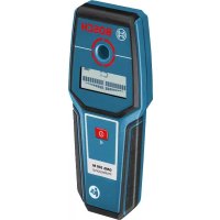



| Product type | Digital metal and live wire detector |
| Brand | Bosch |
| Model | GMS 100 M Professional |
| Dimensions (L x W x H) | 200 x 86 x 32 mm |
| Weight | 260 g (according to EPTA-Procedure 01/2003) |
| Power supply | 1 9 V battery (6LR61) |
| Battery life | Approximately 5 hours |
| Max. detection depth (ferrous metals) | 100 mm |
| Max. detection depth (non-ferrous metals) | 80 mm |
| Max. detection depth (live cables) | 50 mm (110-230 V AC) |
| Operating temperature | -10 °C to +45 °C |
| Storage temperature | -20 °C to +70 °C |
| Max. relative humidity | 80 % |
| Protection rating | IP54 (dust and splash water protected) |
| Automatic shut-off | After approximately 5 minutes without use |
| Display | LCD screen with graduated scales, battery charge indicator, object type icons |
| Audible signal | Yes, can be enabled/disabled |
| Light ring | Green, yellow, red depending on object proximity |
| Main functions | Detection of ferrous metals, non-ferrous metals and live cables |
| Manual calibration | Possible in case of display drift |
| Maintenance and cleaning | Clean with a soft, dry cloth; do not use solvents; do not immerse |
| Safety | Do not use in explosive atmospheres; consult other sources before drilling; do not repair yourself |
| Spare parts and repairability | Repair by an authorized Bosch service center; genuine spare parts |
Frequently Asked Questions - GMS 100 M BOSCH
User questions about GMS 100 M BOSCH
0 question about this device. Answer the ones you know or ask your own.
Ask a new question about this device
Download the instructions for your Detector in PDF format for free! Find your manual GMS 100 M - BOSCH and take your electronic device back in hand. On this page are published all the documents necessary for the use of your device. GMS 100 M by BOSCH.
USER MANUAL GMS 100 M BOSCH
Power Tools Division
70745 Leinfelden-Echterdingen
Germany
www.bosch-pt.com
1609929Y44(2011.04)T/131XXX
1609929Y44
GMS 100 M Professional

BOSCH
Ukrainian page 70
Romanian page 74
Bulgarian page 77
Serbian page 81
Slovenian page 84
GMS 100 M Professional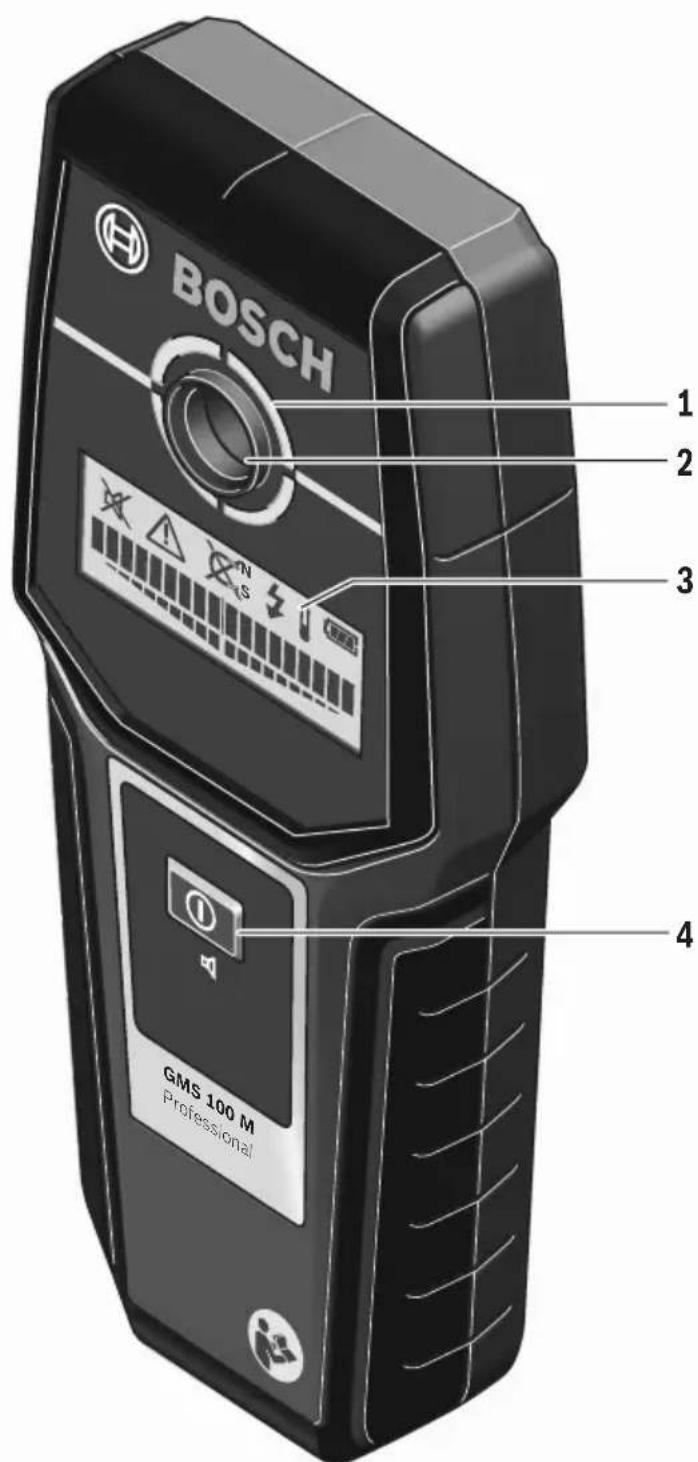
German
Safety Instructions

Senior Vice President
Head of Product
Engineering
Certification

Robert Bosch GmbH, Power Tools Division
D-70745 Leinfelden-Echterdingen
Read and observe all instructions. SAVE THESE INSTRUCTIONS FOR FUTURE REFERENCE.
Have the measuring tool repaired only through qualified specialists using original spare parts. This ensures that the safety of the measuring tool is maintained. Do not operate the measuring tool in explosive environments, such as in the presence of flammable liquids, gases or dusts. Sparks can be created in the measuring tool which may ignite the dust or fumes. For technological reasons, the measuring tool cannot ensure 100% certainty. To rule out hazards, safeguard yourself each time before drilling, sawing or routing in walls, ceilings or floors by means of other information sources, such as building plans, pictures from the construction phase, etc. Environmental influences, such as humidity or closeness to electrical devices, can influence the accuracy of the measuring tool. Surface quality and condition of the walls (e.g., moisture, metallic building materials, conductive wallpaper, insulation materials, tiles) as well as the amount, type, size and position of the objects can lead to faulty measuring results.
Product Description and Specifications
Please unfold the fold-out page with the representation of the measuring tool and leave it unfolded while reading the operating instructions.
Intended Use
The measuring tool is intended for detecting ferrous and nonferrous objects and "live" conductors.
Product Features
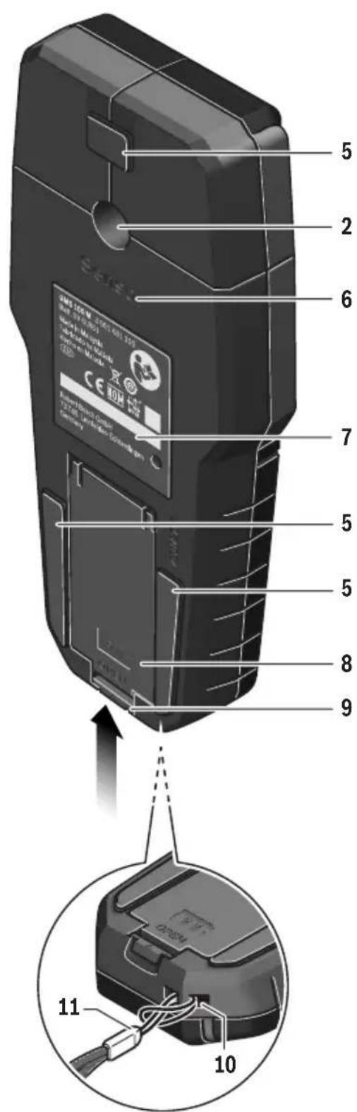
The numbering of the product features shown refers to the illustration of the measuring tool on the graphic page.
1 Illuminated ring
2 Marking hole
3 Display
4 On/Off button
5 Contact pads
6 Sensor area
7 Type plate
8 Battery lid
9 Latch of battery lid
10 Fixture for carrying strap
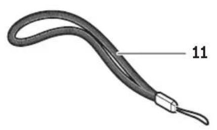
11 Carrying strap
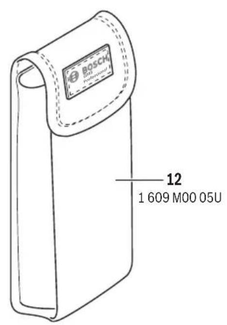
12 Protective pouch*
- The accessories illustrated or described are not included as standard delivery.
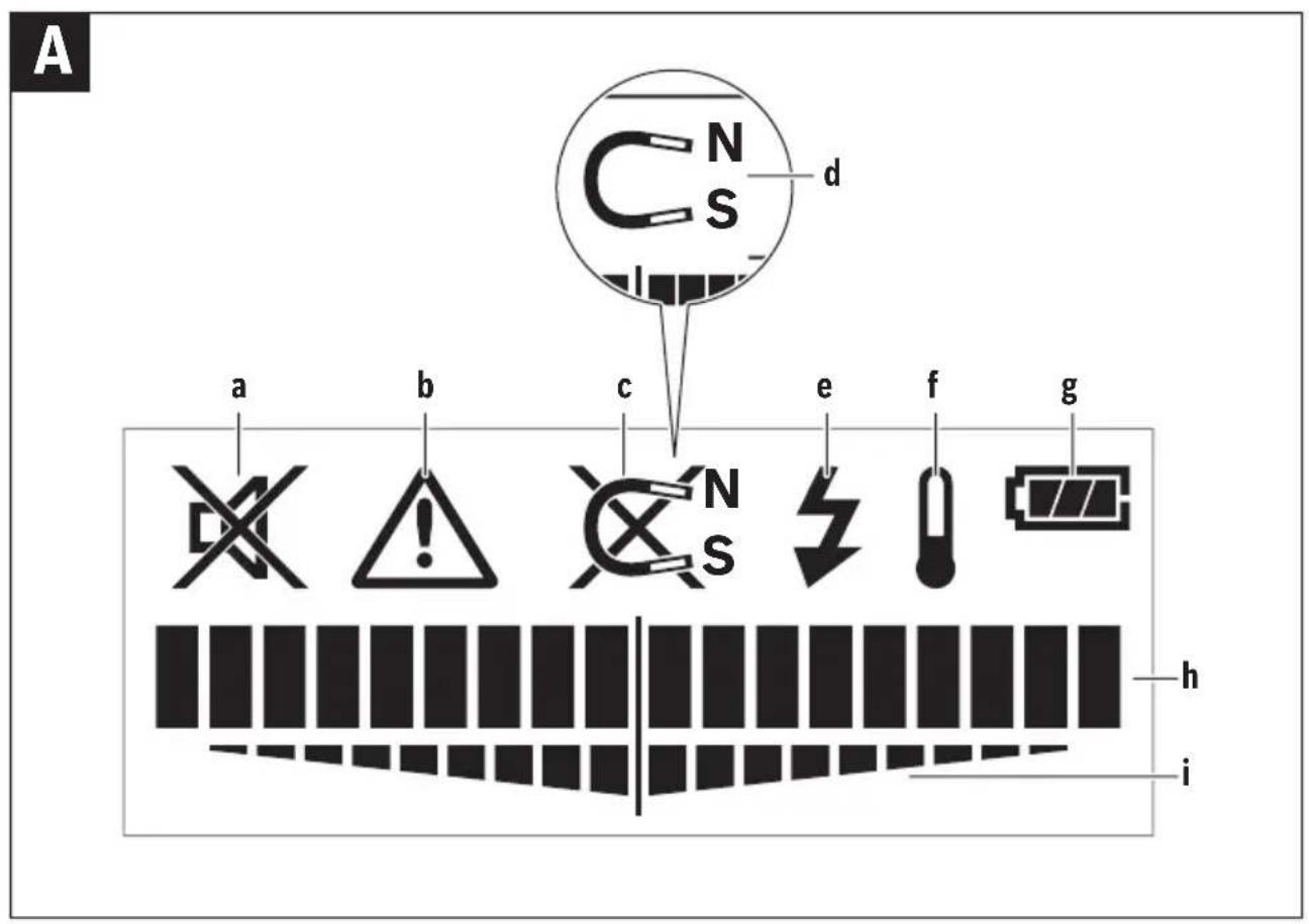
Display Elements (see figure A)
a Switched-off audio signal indicator
b Warning-function indicator
c Indication of the object type "Non-magnetic metal"
d Indication of the object type "Magnetic metal"
e Indication of the object type "Live conductor"
f Temperature control indicator
g Battery indicator
h Main scale
i Fine scale
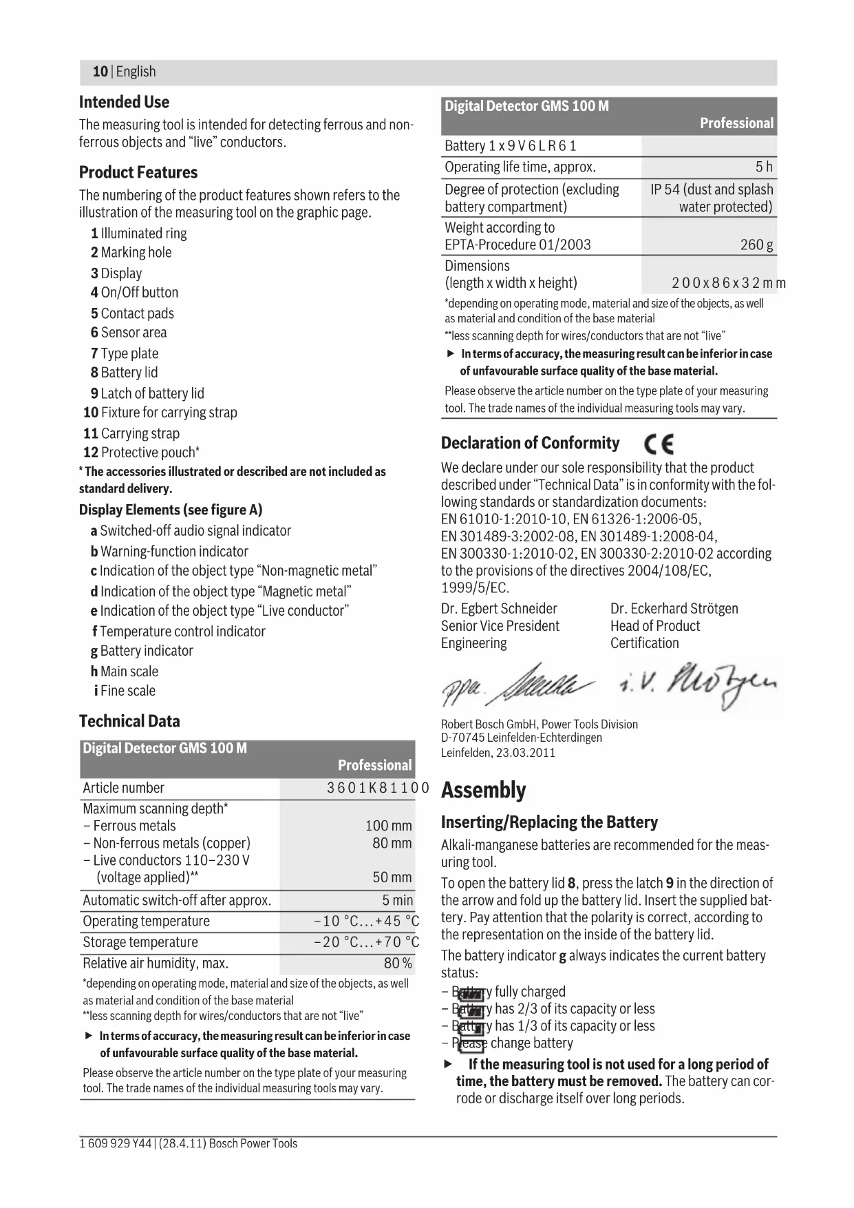
Technical Data
| Digital Detector GMS 100 M | Professional |
| Article number | 3601K81100 |
| Maximum scanning depth* | |
| - Ferrous metals | 100 mm |
| - Non-ferrous metals (copper) | 80 mm |
| - Live conductors 110-230 V(voltage applied)** | 50 mm |
| Automatic switch-off after approx. | 5 min |
| Operating temperature | -10 °C...+45 °C |
| Storage temperature | -20 °C...+70 °C |
| Relative air humidity, max. | 80 % |
depending on operating mode, material and size of the objects, as well as material and condition of the base material *less scanning depth for wires/conductors that are not "live"
In terms of accuracy, the measuring result can be inferior in case of unfavourable surface quality of the base material.
Please observe the article number on the type plate of your measuring tool. The trade names of the individual measuring tools may vary.
| Digital Detector GMS 100 M Professional | |
| Battery 1 x 9 V 6 L R 6 1 | |
| Operating life time, approx. | 5 h |
| Degree of protection (excluding battery compartment) | IP 54 (dust and splash water protected) |
| Weight according to EPTA-Procedure 01/2003 | 260 g |
| Dimensions (length x width x height) | 200 x 86 x 32 m |
| *depending on operating mode, material and size of the objects, as well as material and condition of the base material **less scanning depth for wires/conductors that are not “live” | |
| In terms of accuracy, the measuring result can be inferior in case of unfavourable surface quality of the base material. | |
| Please observe the article number on the type plate of your measuring tool. The trade names of the individual measuring tools may vary. | |
Declaration of Conformity

We declare under our sole responsibility that the product described under "Technical Data" is in conformity with the following standards or standardization documents: EN 61010-1:2010-10, EN 61326-1:2006-05, EN 301489-3:2002-08, EN 301489-1:2008-04, EN 300330-1:2010-02, EN 300330-2:2010-02 according to the provisions of the directives 2004/108/EC, 1999/5/EC.
Dr. Egbert Schneider
Senior Vice President
Engineering
Dr. Eckerhard Strötgen
Head of Product
Certification

Robert Bosch GmbH, Power Tools Division
D-70745 Leinfelden-Echterdingen
Inserting/Replacing the Battery
Alkali-manganese batteries are recommended for the measuring tool.
To open the battery lid 8, press the latch 9 in the direction of the arrow and fold up the battery lid. Insert the supplied battery. Pay attention that the polarity is correct, according to the representation on the inside of the battery lid.
The battery indicator g always indicates the current battery status:
Battery fully charged. Battery has 2/3 of its capacity or less. Battery has 1/3 of its capacity or less - Please change battery. If the measuring tool is not used for a long period of time, the battery must be removed. The battery can corrode or discharge itself over long periods.
Operation
Protect the measuring tool against moisture and direct sunlight. Do not subject the measuring tool to extreme temperatures or variations in temperature. In case of large variations in temperature, allow the measuring tool to adjust to the ambient temperature before switching it on. In case of extreme temperatures or variations in temperature, the accuracy of the measuring tool and the display indication can be impaired. Use or operation of transmitting systems, such as WLAN, UMTS, radar, transmitter masts or microwaves, in the close proximity can influence the measuring function.
Initial Operation
Switching On and Off
Before switching the measuring tool on, make sure that the sensor area 6 is not moist. If required, dry the measuring tool using a soft cloth. If the measuring tool was subject to an extreme temperature change, allow it to adjust to the ambient temperature before switching on.
To switch on the measuring tool, press the On/Off button 4. To switch off the measuring tool, press the On/Off button 4 again.
When no button on the measuring tool is pressed for approx. 5 minutes and when no objects are detected, the measuring tool automatically switches off to save the battery.
Switching the Audio Signal On/Off
When the measuring tool is switched on, the audio signal can be switched on or off by pressing the On/Off button 4 for a few seconds. When the audio signal is switched off, indication a appears on the display.
Method of Operation (see figures A-B)
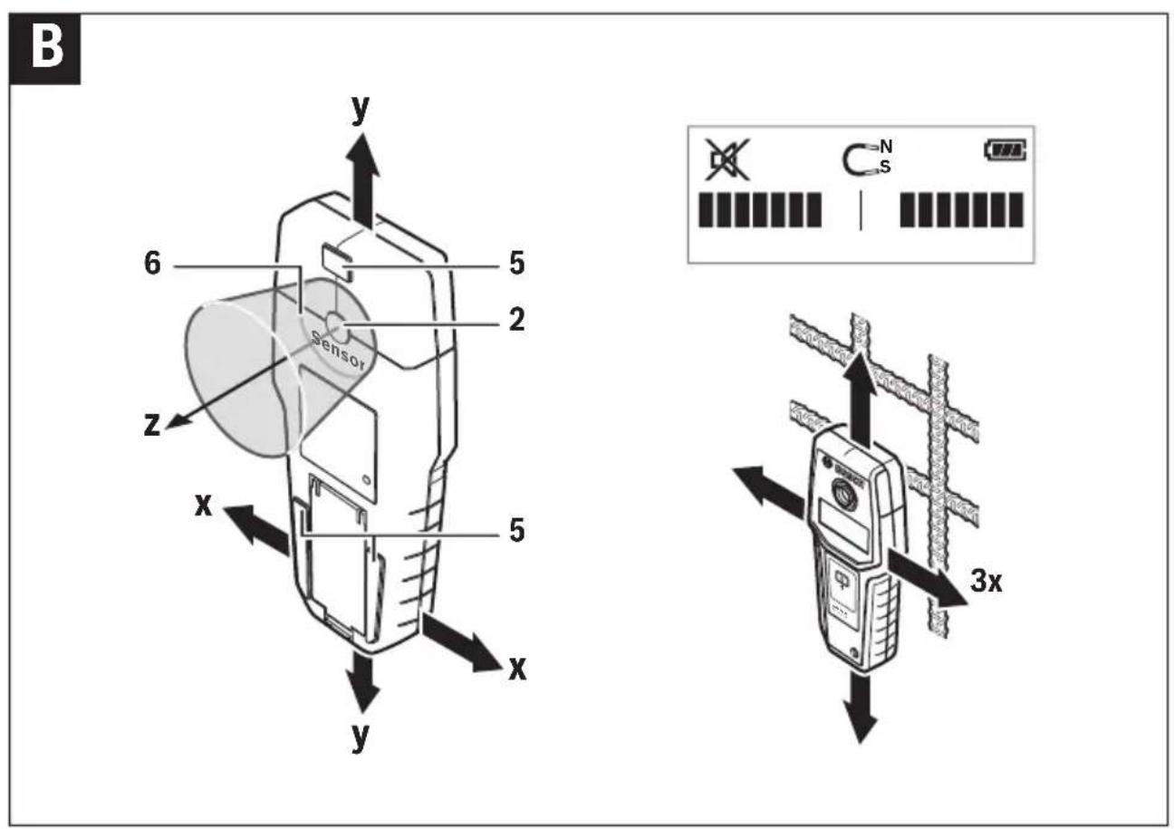
The measuring tool checks the base material of sensor area 6 in measurement direction z to the max. detection depth (see "Technical Data"). Objects are detected that differ from the material of the wall.
Always move the measuring tool in a straight line over the surface applying slight pressure, without lifting it off or changing the pressure. During measurement, the contact pads 5 must always have contact to the surface.
Measuring Procedure
After switching on, the illuminated ring 1 lights up green.
Position the measuring tool against the surface being detected and move it toward the x - and y -axis. When the measuring tool comes closer to an object, the amplitude in the main scale h increases and ring 1 lights up yellow; when it is moved away from the object, the amplitude decreases. The main scale h indicates the maximal amplitude above the object; ring 1 lights up red and an audio signal sounds. For small or deeply embedded objects, ring 1 can continue to light up yellow, while there is no audio signal.
Wide objects are not indicated by the illuminated ring or the audio signal throughout their complete width.
As soon as the measuring tool has localised an object below the centre of the sensor, the fine scale i is activated.
To localise the object more precisely, move the measuring tool repeatedly (3x) back and forth over the object.
The fine scale i indicates a maximum amplitude when the object is positioned precisely below the centre of the sensor, independent of how many bars are displayed in the main scale h.
When searching for very small or deeply embedded objects and the main scale h reacts only slightly, move the measuring tool repeatedly over the object in the horizontal (x-axis) and vertical (y-axis) directions. Observe the amplitude of the fine scale i.
Before drilling, sawing, or routing into a wall, protect yourself against hazards by using other information sources. As the measuring results can be influenced by ambient conditions or the wall material, there may be a hazard even though the indicator does not indicate an object in the sensor range (no audio signal or beep and the illuminated ring 1 lit green).
Metal
When the detected metal object is of magnetic metal (e.g., iron), the symbol d is indicated on display 3. For non-magnetic metals, the symbol c is indicated. In order to differentiate between metal types, the measuring tool must be positioned above the detected metal object (ring 1 is lit red and fine scale i indicates a high amplitude).
Note: For reinforcement steel mesh and steel in the examined base material, an amplitude is indicated over the complete surface of the main scale h. For reinforcement steel mesh, it is typical that the symbol d for magnetic metal is indicated on the display directly above the iron rods, whereas between the iron rods, the symbol c for non-magnetic metal will appear.
Power Cable
When a "live" conductor is detected, indication e appears on the display 3. Move the measuring tool repeatedly over the area to localise the "live" conductor more precisely. After moving over the "live" conductor several times, it can be indicated very accurately. When the measuring tool is very close to the conductor, the illuminated ring 1 rapidly flashes red and the audio signal beeps swiftly.
Notes:
- "Live" conductors can be detected easier when power consumers (e.g., lamps, machines) are connected to the sought conductor and switched on.
- Under certain conditions (such as below metal surfaces or behind surfaces with high water content), "live" conductors cannot be securely detected. The signal strength of a "live" conductor depends on the position of the cable. Therefore, apply further measurements in close proximity or use other information sources to check if a "live" conductor exists.
- Voltage-free conductors can be detected as metal objects. This does not apply for stranded conductors (contrary to solid conductors or cable). Static electricity can lead to inaccurate indication of electric lines, e.g., over a large range. To improve the indication, place your free hand flat on the wall next to the measuring tool, in order to remove the static electricity.
Working Advice
- Measuring values can be impaired through certain ambient conditions. These include, e.g., the proximity of other equipment that produce strong magnetic or electromagnetic fields, moisture, metallic building materials, foil-laminated insulation materials or conductive wallpaper or tiles. Therefore, please also observe other information sources (e.g. construction plans) before drilling, sawing or routing into walls, ceilings or floors.
Marking Objects
If required, detected objects can be marked. Perform a measurement as usual. Once you have found the boundaries or the centre of an object, mark the sought location through the marking hole 2.
Temperature Control
The measuring tool is equipped with a temperature control indicator, as accurate measurements are only possible as long as the temperature within the measuring tool remains constant.
When the temperature control indicator f lights up, the measuring tool is not within the operating temperature range or was subject to large variations in temperature. Switch the measuring tool off and allow it to adjust to the ambient temperature before switching it on again.
Warning Function
When indicator b lights up on the display, the measurement must be restarted. Remove the measuring tool from the wall and place it on the base material at a different location.
When indicator b flashes on display 3, send the measuring tool to an authorised customer services agent.
Recalibration
When the main scale h indicates a continuously high amplitude, even though there is no object near the measuring tool, the measuring tool can be manually recalibrated.
- Switch the measuring tool off.
- Remove all objects near the measuring tool that could be detected, including your wrist watch or rings made of metal, and hold the measuring tool up.
Pay attention that battery indicator g indicates at least 1/3 capacity:
- Switch the measuring tool on again. When the measuring tool starts, immediately press and hold the the On/Off button 4. Hold the On/Off button until the illuminated ring 1 slowly flashes red, indicating the calibration of the measuring tool.
- When the calibration was successful, ring 1 lights up green and the measuring tool automatically becomes ready for operation again.
Note: If the measuring tool does not start automatically, repeat the recalibration. If the measuring tool still does not start, send it to an authorized customer service agent.
Maintenance and Service
Maintenance and Cleaning
- Check the measuring tool each time before use. In case of visible damage or loose components inside the measuring tool, safe function can no longer be ensured.
Keep the measuring tool clean and dry at all times to ensure proper and safe working.
Do not immerse the measuring tool in water or other fluids.
Wipe away debris or contamination with a dry, soft cloth. Do not use cleaning agents or solvents.
In order not to affect the measuring function, decals/stickers or name plates, especially metal ones, may not be attached in the sensor area 6 on the front or back side of the measuring tool.
Do not remove the contact pads 5 on the backside of the measuring tool.
If the measuring tool should fail despite the care taken in manufacturing and testing procedures, repair should be carried out by an authorized after-sales service centre for Bosch power tools. Do not open the measuring tool yourself.
In all correspondence and spare parts orders, please always include the 10-digit article number given on the type plate of the measuring tool.
After-sales Service and Customer Assistance
Our after-sales service responds to your questions concerning maintenance and repair of your product as well as spare parts. Exploded views and information on spare parts can also be found under:
www.bosch-pt.com
Our customer service representatives can answer your questions concerning possible applications and adjustment of products and accessories.
Great Britain
Robert Bosch Ltd. (B.S.C.)
P.O.Box 98
Broadwater Park
North Orbital Road
Denham
Uxbridge
UB95HJ
Tel. Service: +44 (0844) 736 0109
Fax: +44 (0844) 736 0146
E-Mail: boschservicecentre@bosch.com
Ireland
Origo Ltd.
Unit 23 Magna Drive
Magna Business Park
City West
Dublin 24
Tel. Service: +353 (01) 466 67 00
Fax: +353 (01) 466 68 88
Australia, New Zealand and Pacific Islands
Robert Bosch Australia Pty. Ltd.
Power Tools
Locked Bag 66
Clayton South VIC 3169
Customer Contact Center
Inside Australia:
Phone: +61 (01300) 307 044
Fax: +61 (01300) 307 045
Inside New Zealand:
Phone: +64 (0800) 543 353
Fax: +64 (0800) 428 570
Outside AU and NZ:
Phone: +61 (03) 9541 5555
www.bosch.com.au
Republic of South Africa
Customer service
Hotline: +27 (011) 651 9600
Gauteng - BSC Service Centre
35 Roper Street, New Centre
Johannesburg
Tel.: +27 (011) 493 93 75
Fax: +27 (011) 493 0126
E-Mail: bsctools@icon.co.za
KZN - BSC Service Centre
Unit E, Almar Centre
143 Crompton Street
Pinetown
Tel.: +27 (031) 7012120
Fax: +27 (031) 7012446
E-Mail: bsc.dur@za.bosch.com
Western Cape - BSC Service Centre
Democracy Way, Prosperity Park
Milnerton
Tel.: +27 (021) 5512577
Fax: +27 (021) 5513223
E-Mail: bsc@zsd.co.za
Bosch Headquar
Midrand, Gauteng
Tel.: +27 (011) 6519600
Fax: +27 (011) 6519880
E-Mail: rbsa-hq.pts@za.bosch.com
People's Republic of China
China Mainland
Bosch Power Tools (China) Co., Ltd.
567, Bin Kang Road
Bin Jiang District 310052
Hangzhou, P.R.China
Service Hotline: 400 826 8484
Fax: +8657187774502
E-Mail: contact.ptcn@cn.bosch.com
www.bosch-pt.com.cn
HK and Macau Special Administrative Regions
Robert Bosch Hong Kong Co. Ltd.
21st Floor, 625 King's Road
North Point, Hong Kong
Customer Service Hotline: +852 (21) 02 02 35
Fax: +852 (25) 90 97 62
E-Mail: info@hk.bosch.com
www.bosch-pt.com.hk
Indonesia
PT. Multi Tehaka
Kawasan Industri Pulogadung
Jalan Rawa Gelam III No. 2
Jakarta 13930
Indonesia
Tel.: +62 (21) 4683 25 22
Fax: +62 (21) 46828645/6823
E-Mail: sales@multitehaka.co.id
www.multitehaka.co.id
Philippines
Robert Bosch, Inc.
28th Floor Fort Legend Towers,
3rd Avenue corner 31st Street,
Fort Bonifacio Global City,
1634 Taguig City, Philippines
Tel.: +63 (2) 870 3871
Fax: +63 (2) 870 3870
matheus.contiero@ph.bosch.com
www.bosch
Bosch Service Center:
9725-27 Kamagong Street
San Antonio Village
Makati City, Philippines
Tel.: +63 (2) 899 9091
Fax: +63 (2) 897 6432
rosalie.dagdagan@ph.bosch.com
Malaysia
Robert Bosch (S.E.A.) Pte. Ltd.
No.8A, Jalan 13/6
G.P.O. Box 10818
46200 Petaling Jaya
Selangor, Malaysia
Tel.: +60 (3) 7966 3194
Fax: +60 (3) 7958 3838
cheehoe.on@my.bosch.com
Toll-Free: 1800 880 188
www.bosch-pt.com.my
Thailand
Robert Bosch Ltd.
Liberty Square Building
No.287, 11th Floor
Silom Road, Bangrak
Bangkok 10500
Tel.: +66 (2) 631 1879 - 1888 (10 lines)
Fax: +66 (2) 2384783
Robert Bosch Ltd., P. O. Box 2054
Bangkok 10501, Thailand
Bosch Service - Training Centre
2869-2869/1 Soi Ban Kluay
Rama IV Road (near old Paknam Railway)
Prakanong District
10110 Bangkok
Thailand
Tel.: +66 (2) 6717800-4
Fax: +66 (2) 2494296
Fax: +66 (2) 2495299
Singapore
Robert Bosch (SEA) Pte. Ltd.
11 Bishan Street 21
Singapore 573943
Tel.: +65 6571 2772
Fax: +65 6350 5315
leongheng.leow@sg.bosch.com
Toll-Free: 1800 333 8333
www.bosch-pt.com.sg
Vietnam
Robert Bosch Vietnam Co. Ltd
10/F, 194 Golden Building
473 Dien Bien Phu Street
Ward 25, Binh Thanh District
84 Ho Chi Minh City
Vietnam
Tel.: +84 (8) 6258 3690 ext. 413
Fax: +84 (8) 62583692
hieu.lagja@vn.bosch.com
www.bosch-pt.com
Disposal
Measuring tools, accessories and packaging should be sorted for environmental-friendly recycling.
Do not dispose of measuring tools and batteries/rechargeable batteries into household waste!
Only for EC countries:

According to the European Guideline 2002/96/EC, measuring tools that are no longer usable, and according to the European Guideline 2006/66/EC, defective or used battery packs/batteries, must be collected separately and disposed of in an environmentally correct manner.
Batteries no longer suitable for use can be directly returned at:
Great Britain
Robert Bosch Ltd. (B.S.C.)
P.O. Box 98
Broadwater Park
North Orbital Road
Denham
Uxbridge
UB 95HJ
Tel. Service: +44 (0844) 736 0109
Fax: +44 (0844) 736 0146
E-Mail: boschservicecentre@bosch.com
Subject to change without notice.
Français
Dr. Egbert Schneider Senior Vice President Engineering
Dr. Eckerhard Strötgen Head of Product Certification

Robert Bosch GmbH, Power Tools Division D-70745 Leinfelden-Echterdingen Leinfelden, 23.03.2011
Montage
Robert Bosch (France) S.A.S.
Dr. Egbert Schneider Senior Vice President Engineering
Dr. Eckerhard Ströttgen Head of Product Certification

Robert Bosch GmbH, Power Tools Division D-70745 Leinfelden-Echterdingen Leinfelden, 23.03.2011
Assembly
Senior Vice President
Engineering
Dr. Eckerhard Strötgen
Head of Product
Certification

Robert Bosch GmbH, Power Tools Division
D-70745 Leinfelden-Echterdingen
Senior Vice President
Engineering
Dr. Eckerhard Strötgen
Head of Product
Certification

Robert Bosch GmbH, Power Tools Division
D-70745 Leinfelden-Echterdingen
Senior Vice President
Head of Product
Engineering
Certification

Robert Bosch GmbH, Power Tools Division
D-70745 Leinfelden-Echterdingen
Dr. Egbert Schneider Senior Vice President Engineering
Dr. Eckerhard Strötgen Head of Product Certification

Robert Bosch GmbH, Power Tools Division
D-70745 Leinfelden-Echterdingen
Bosch Service Center
Telegrafvej 3
2750 Ballerup
Tel. Service Center: +45 (4489) 8855
Fax: +45 (4489) 87 55
E-Mail: vaerktoej@dk.bosch.com
Disposal
Dr. Egbert Schneider Senior Vice President Engineering
Dr. Eckerhard Strötgen Head of Product Certification
Robert Bosch GmbH, Power Tools Division
D-70745 Leinfelden-Echterdingen
Bosch Service Center
Telegrafvej 3
2750 Ballerup
Denmark
Tel.: +46 (020) 41 44 55
Fax: +46 (011) 187691
Waste disposal
Dr. Egbert Schneider Senior Vice President Engineering
Dr. Eckerhard Strötgen Head of Product Certification

Robert Bosch GmbH, Power Tools Division
D-70745 Leinfelden-Echterdingen
Dr. Egbert Schneider Senior Vice President Engineering
Dr. Eckerhard Strötgen Head of Product Certification

Robert Bosch GmbH, Power Tools Division
D-70745 Leinfelden-Echterdingen
The measuring tool is intended for the detection of metal and metal-containing objects as well as live wires.
The measuring tool is intended for the detection of metal and metal-containing objects as well as live wires.
Product features
The numbering of the product features refers to the illustration of the measuring tool on the graphic page.
1 Light-emitting diode 2 Opening for measuring plate 3 Measuring plate 4 ON/OFF button 5 Battery compartment 6 Battery compartment cover 7 Type plate 8 Battery compartment cover latch 9 Safety of the battery compartment cover
10 YnOdoXn KpOboviou μeTaΦopαs
11Kopδoviμetaφopd 12 Toavra npootaoiac
- EApriiura nou anekoviciotai nepiypapovtai dev nepieoxovta otn otavtp oukeuaia.
T01xieia e6eIeWv (BaeEikova A)
aEvdeiE yia anevepyoinmuvoakouotiko onma bEvdeiŋtncλeitoupyia npoeioboinong c'Ev6eIη eIδouc avTkeiμεvou «Mn paayntko μεtaλλo» d'EvdeiEi eioucavtkemuevou "Mayvtko taaloo eEvdeiE iBouc avtkeivou «Hlektpoopocaywyoc fEv6eIg enrrnponc 0epoKpaia gEv6e1n μnatapact h Kupia kaiiaka iKlipaka μikopupuonc
Texvka xaapaktnpOtuKa
Dr. Egbert Schneider Senior Vice President Engineering
Dr. Eckerhard Strötgen Head of Product Certification
ppa 1b 1 = µ · p 0d 0
Robert Bosch GmbH, Power Tools Division D-70745 Leinfelden-Echterdingen Leinfelden, 23.03.2011
Συναρμολόγηση
Dr. Egbert Schneider Senior Vice President Engineering
Dr. Eckerhard Strötgen Head of Product Certification

Robert Bosch GmbH, Power Tools Division
D-70745 Leinfelden-Echterdingen
Bosch San. ve Tic. A.S.
Ahi Evran Cad. No:1 Kat:22
Polaris Plaza
80670 Maslak/Istanbul
Customer Service: +90 (0212) 335 06 66
Customer Service Line: +90 (0212) 335 07 52
Liquidation
Senior Vice President
Engineering
Dr. Eckerhard Strötgen
Head of Product
Certification
Robert Bosch GmbH, Power Tools Division
D-70745 Leinfelden-Echterdingen
Robert Bosch Sp. z o.o.
Dr. Egbert Schneider Senior Vice President Engineering
Dr. Eckerhard Ströttgen Head of Product Certification

Robert Bosch GmbH, Power Tools Division
D-70745 Leinfelden-Echterdingen
Bosch Service Center PT
K Vapence 1621/16
692 01 Mikulov
Senior Vice President
Engineering
Dr. Eckerhard Strötgen
Head of Product
Certification

Robert Bosch GmbH, Power Tools Division
D-70745 Leinfelden-Echterdingen
Senior Vice President
Head of Product
Engineering
Certification

Robert Bosch GmbH, Power Tools Division
D-70745 Leinfelden-Echterdingen
Dr. Egbert Schneider Senior Vice President Engineering
Dr. Eckerhard Strötgen Head of Product Certification
Robert Bosch GmbH, Power Tools Division
D-70745 Leinfelden-Echterdingen
When the battery is almost empty, the measuring tool will automatically switch off. No buttons will be pressed and no functions will be detected on the measuring tool.
Switching the acoustic signal on/off
You can switch the acoustic signal on or off by pressing the switch for a few seconds. When the measuring tool is switched on, the indicator will appear on the display.
Operation (see figures A-B)
Using the measuring instrument, check the foundation under the sensor zone 6 in the Z direction to the max. measurement depth (see "Technical Data"). The instrument detects objects consisting of material denser than the wall.
Move the measuring instrument over the surface evenly and in a straight line, with light pressure, without lifting it and without changing the pressure force. During measurement, the contact plates 5 must be constantly in contact with the base.
Measurement
After switching on, the indicator 1 lights up with a green light.
Place the measuring instrument on the surface to be examined and move it in the direction of the X and Y axes. As the measuring instrument approaches an object, the value on the main scale increases and the indicator 1 lights up with a yellow light; as it moves away from the object, the value decreases. Above the object, the main scale reaches its maximum value; the indicator 1 lights up with a red light and an audible signal sounds. For small or deeply buried objects, the indicator 1 may continue to light up with a yellow light, and the audible signal may not sound.
Large objects are displayed with the ring lighting up and the signal sounding over the entire width.
If the center of the sensor zone is above an object, the fine search scale is activated.
For more precise localization of the object, move the measuring instrument over the object in a cross pattern (3 times).
The value on the fine search scale i reaches its maximum size if the object is located exactly under the center of the sensor zone, regardless of how many bars are displayed on the main scale.
For deeply buried objects, when the main scale reacts weakly, perform the measurement with the measuring instrument several times in the horizontal (X axis) and vertical (Y axis) directions over the object. Follow the value on the fine search scale i.
Before performing drilling, cutting, or milling, you must obtain information from other sources. Since factors of the surrounding environment or wall construction can negatively affect measurement results, there is a risk even if the indicator does not display objects in the sensor zone (absence of audible signal, the ring 1 lights up green).
Metal
If the object is made of magnetic metal (e.g., iron), the symbol B is displayed on the display. In the case of non-magnetic metals, the symbol C is displayed. In order for the measuring instrument to distinguish between types of metal, it must be located above the metal object (ring 1 lights up red, and the value on the fine search scale i reaches its maximum size).
Note: When reinforcing steel meshes and reinforcement are found in the examined base, the value on the main scale is displayed over the entire width of the object. Usually, when steel meshes are detected directly above iron pipes, the symbol for magnetic metals d lights up on the display, and between the pipes - the symbol for non-magnetic metals c.
Conductive cable
The voltage detector indicates the presence of voltage. To more accurately locate the position of the voltage-carrying conductor, repeat the measurement with the measuring instrument on the surface. After several applications of the conductor under voltage, it is displayed with high accuracy. If the measuring instrument is very close to the conductor, the LED indicator flashes red at a fast rate and emits a series of acoustic signals with short pauses.
Instructions:
- The conductor under voltage is detected if consumers of current (e.g., lamps or devices) are connected to the conductor being sought and they are switched on. - Under certain conditions (e.g., under metal surfaces or surfaces with high moisture content), the conductor under voltage may not be detected. The signal strength for the conductor under voltage depends on the type of conductor. Therefore, recheck with further measurements in the immediate vicinity or consult other sources of information to determine whether the conductor is under voltage. - A conductor not under voltage is detected as a metal object. Multi-core cables are not detected in this case (unlike cables with a metal shield). - Static electricity can cause the conductor to be detected inaccurately, e.g., over a large area. To improve the indication, place your free hand flat against the wall next to the measuring instrument to discharge static electricity.
Application instructions
Due to the principle of operation of the measuring instrument, certain environmental conditions can influence or falsify the measurement. These include, for example, proximity to devices emitting strong magnetic or electromagnetic fields, moisture, building materials containing metal, insulating materials, aluminum cladding, conductive wallpaper or tiles.
Therefore, before drilling, cutting, or milling into walls, ceilings, or floors, also consider other sources of information (e.g., construction drawings).
Marking objects
If necessary, you can mark the location of detected objects. Proceed as usual.
After detecting a live or non-live object, mark the desired location through the marking opening 2.
Temperature control
The measuring instrument is equipped with a temperature control device, because accurate measurement is only possible at a stable temperature inside the measuring instrument.
The illumination of the temperature control indicator f indicates that the measuring instrument has left the range of operating temperature or is experiencing rapid temperature fluctuations. Switch off the measuring instrument and allow it to stabilize to the temperature before switching it on again.
Temperature pre-warning function
If the indicator b lights up, the measurement must be repeated. Remove the measuring instrument from the wall and apply it to the base at another location.
If the indicator 3 lights up, send the measuring instrument to an authorized workshop.
Calibration of the main unit can be performed manually even if there is no object near the measuring instrument.
- Turn off the measuring instrument. -While the measuring instrument is in operation, remove all objects that it could react to, including your hands or metal parts, and hold the instrument in the air. Make sure that the battery charge indicator shows at least 1/3 capacity. -Turn the measuring instrument back on. When the measuring instrument starts working, immediately press the switch 4 and hold it pressed. Hold the switch pressed until the LED starts flashing red in a slow rhythm, which indicates that the measuring instrument is being calibrated. -After the calibration process is complete, the LED starts flashing green and the measuring instrument automatically returns to operation.
Note: If the measuring instrument does not turn on automatically, repeat the calibration. If the measuring instrument does not turn on after this, please send it to an authorized service center.
Maintenance and service
Maintenance and cleaning
Check the measuring instrument regularly. If visible damage or loose parts are found inside the measuring instrument, reliable operation is no longer guaranteed.
To ensure high-quality and safe operation, always keep the measuring instrument clean and dry.
Never immerse the measuring instrument in water or other liquids.
Wipe off dirt with a dry, soft cloth. Do not use any cleaning agents or solvents.
To avoid distorting the measurement process, do not place stickers or labels, especially metal labels, in the sensor area 6 on the front or back of the measuring instrument.
Do not remove the contact strips 5 on the front side of the measuring instrument.
If, despite careful handling and testing, the measuring instrument still fails, repairs must be carried out by an authorized service center for electrical tools Bosch. Do not open the measuring instrument yourself.
Please, in all inquiries and orders, always specify the product number from the nameplate of the measuring instrument.
Service and customer consultation
The service center will answer all your questions regarding repair and maintenance of your product, as well as spare parts. You will also find assembly drawings and spare parts information at:
www.bosch-pt.com
The Bosch consultant team will be happy to assist you with questions about purchasing, application, and setup of products and accessories.
Region: Russia, Belarus, Kazakhstan
Warranty service and repair of power tools, in compliance with the requirements and standards of the manufacturer, are carried out in all countries only at authorized service centers of Robert Bosch. WARNING! Use of counterfeit products is dangerous during operation and may cause harm to your health. Manufacturing and distribution of counterfeit products is prosecuted in accordance with administrative and criminal law.
Russia
Robert Bosch LLC
Service center for power tool maintenance, Akademika Koroleva str., 13/5
129515, Moscow
Russia
Tel.: +7 (800) 100 8007
E-Mail: pt-service@ru.bosch.com
You can get full information about the location of service centers on the official website www.bosch-pt.ru or by phone of the Bosch information and service hotline 8-800-100-8007 (toll-free call).
Belarus
Robert Bosch LLC
Service Center for Power Tools. Timiryazeva, 65A-020
220035, Minsk
Belarus
Tel.: +375 (17) 254 78 71
Tel.: +375 (17) 254 79 15/16
Fax: +375 (17) 254 78 75
E-Mail: pt-service@by.bosch.com
Official website: www.bosch-pt.by
Kazakhstan
LLC "Robert Bosch"
Service Center for Power Tools
ul. Seryumina
050037, Almaty
Kazakhstan
Tel.: +7 (727) 232 37 07
Phone: +7 (727) 2511336
E-Mail: pt-service@kz.bosch.com
Official website: www.bosch-pt.kz
Utilization
Used measuring tools, accessories and packaging should be recycled in an environmentally friendly way.
Do not throw measuring tools and batteries/accumulators into household waste!
Only for EU countries:
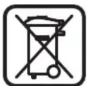
According to the European Directive 2002/96/EC, used measuring tools must be collected separately and recycled in an environmentally friendly way. According to the European Directive 2006/66/EC, defective or exhausted batteries/accumulators must be collected separately and recycled in an environmentally friendly way.
Subject to change.
Ukrainian
Safety instructions

Read and follow all safety instructions. Keep these instructions for future reference.
Have your measuring tool repaired only by qualified specialists and only with original spare parts. This will ensure that your measuring tool remains safe. Do not work with the measuring tool in explosive atmospheres where there is a risk of explosion due to the presence of flammable liquids, gases or dust.
The measuring tool may be used only with the accessories specified in the operating instructions.
The measuring tool is not suitable for use in areas with a high risk of explosion. To avoid danger, before drilling, sawing or milling into walls, ceilings or floors, check for hidden electrical cables, gas pipes or water pipes. Environmental factors, e.g., moisture, other electrical devices in the vicinity, or the condition of the walls (e.g., moisture, building materials containing metal, wallpaper with conductive properties, insulating materials, paint) can affect the accuracy of the measuring tool. The construction and condition of the walls (e.g., moisture, building materials containing metal, wallpaper with conductive properties, insulating materials, paint), as well as the quantity, type, size and position of the objects, can influence the measurement results.
Onc npoaykty i nocayr
The numbering of the component images follows the images in the operating instructions on the page with the figure.
1 On/off switch 2 Drilling/chisel mode selector 3 Display 4 Battery pack 5 Contact strips 6 Sensor zone 7 Nameplate 8 Battery compartment cover 9 Battery pack latch
10 Drilling spindle
11 Spindle 12 Protective cap*
- The images shown are for illustration purposes and are not part of the standard delivery.
Senior Vice President
Engineering
Dr. Eckerhard Strötgen
Head of Product
Certification
i.v. M 1O 2 y.cn
Robert Bosch GmbH, Power Tools Division
D-70745 Leinfelden-Echterdingen
BKNOPNCOTByBaTH BKNIAUHO AYXHO-MapraHcEbe6aTapei.
IooB BiKpnTH KpnuKy cekuiAaTapeiok 8,HaTnCiHb Ha
fikcTop 9 B HnnpMky CtpiAkn iPiHIMiTb Kpnkcy cekii I
6atapeyok yropy. BCTaBte 6atapeyo.CaikyuTe pni cybomy 3a TpaBnAbHM po3TaUyBaHHM IOAIOciB, RaIe IOKa3aHO BCEpeHIni cekii dA 6atapeyoK.
IHANKAToP 3apJxKeHocTi 6aTapeiOK g 3aBXdN BiO6paXae aKtyaBnH CTyPiHb 3apJxKeHocTi 6aTapeiOK:
-67Tae TIOBHiCTO 3apRKeHa -673pe3ap4xkeHa Ha 2/3 BiD ii EMHOCTi abo MeHwe - 6atpea3apdxkeha 1/3 BiD ii EMHOCTi a60 MeHwe -6TapeIOIOTpiHO3amIHNTI
Kkuo Bn He 6ydeTe KOpHCTyBaTHcB HmipIOBaIbHM TPnAAOM TPOTAROM TPNBaIoro Yacy, BNMaHTe 6atapeo. Pn TpNBAOMy 36epiraHHi 6atapeer MoKe KOPOaYBaTH aO CaMOPo3PraXaTHcR.
EkCnIyatauia
3axuainTe BmipbBaBnPiuaB BiA BOaH i coHauHx PpomeHIB. He DoTyckaIe BtANBy Ha BHMipIOBaIbHN IPNAAd ekCTpeMaIbHnx TEMIepaTp Ta TEMIepaTyPHNX TepaIb. RaIO BHMipIOBaIbHN IPNAAd 3a3HAV BtANBy TepePaDy TEMIepaTp, Tepu HIX BMHKATN NoRo, DaTe Nomy Cta6i3yBatn CBOIO TEMIepaTpY. EkCTpeMaIbHi TEMIepaTpyn Ta TEMIepaTpHi TpePAnMoKyTB IogipWbATn ToHicThB BMIPIOBaIbHO TPNAAdy Ta BtANBaTHa RKiCtB 3o6paXeHHHa DNCTAei. BnKOpHCTaHH a6o ekCTaYatauia B 6e3IOcepeaHi 6An3bKOcTI IepeAbauiB, TaKnx, AKN HApN., 6e3IPObiDi Hi oKaAlbHI O6UncAOBaAlbHi Mepexi, YMTC, paAdapn KOHTPOAU IOBITpHoro Ipoctopy, paIoouran a60 mIKPOXBAbOBI PeuI, MOKe BNTANHyTuHa pe3yAbTaTH BnMIPIOBAHH.
TouaToK po60Tu
BMKAHHBMMKAHH
TepeBMMKahHBMHmipIOBaIbHOrOITpHaAdy TepeBipTe,06ceHCopHa3oHa6He6yHaBOAoROIO.RKIO Heo6XiHo,BnTpiB BMmipIOBaIbHINPiHaADfAnuipKOIO. He BMHKaTe BHMipIOBaIbHN TpHAAd TicAepePaDy TEMPePaTy pEBHH qac,doKN TEMPePaTy pHAAdy He cta6iAl3yEcTbcra.
U06 yBIMKHyTN BnMipHOBaHbHn IpHaaD, HaTNCiTb Ha BnMKa4 4.
U06BMMKHTN BHMIPIOBaIbHIN IpHAAd,HaTNCiTb Ha BMMKa4 4.
A KIOI IPOTAROM Pn6A.5 XBnA.Ha BmIpOBAbHOMy PnAAi He 6yde HATNCHYta XoDA HA KHOITKa i PnAAd HE BnRBNTb HIKNX 06'KtIB,TO PnAAd,IO63aoaADHTb 6aTaPeIO,ABTomauHO BmHKAETbCra.
BbIMKHeHHBbMKeHH3ByKOBOrO CnHa
Press and hold button 4 to turn the sound signal on or off. When the sound signal is on, indicator a will light up on the display.
Operating principle (see Fig. A-B)
The measuring device is moved over the surface to be measured. The main measuring device (see section "Technical Data") has a flat measuring surface. Move the measuring device smoothly over the surface, pressing lightly on it, without lifting it and without pressing too hard. The measuring device must have contact with the surface.
Measuring procedure
After switching on, the device is ready for use and the green LED lights up.
After measuring, wipe the measuring device with a dry cloth and store it in a dry place. When the measuring device is brought close to an object, the main scale reading increases and the green LED lights up. When the device is moved away from the object, the reading decreases. When the object is at the maximum distance, the green LED lights up and a sound signal sounds. For small objects or objects that are very deep, the green LED may light up but the sound signal may not sound.
The green LED or sound signal indicates a wide object, not just its entire width.
The center of the measuring zone is indicated by the object, which is activated by the button.
For better detection of the object, perform the measurement with the device over the object several times (e.g., in a grid pattern).
The main scale reading reaches its maximum when the object is exactly in the center of the measuring zone, regardless of how many bars are displayed on the main scale.
For flat or deeply embedded objects, when the main scale reading is weak, perform the measurement several times with the device over the object in both horizontal (x-axis) and vertical (y-axis) directions. Follow the main scale reading.
Before performing drilling, cutting, or recessing work in walls, you must protect yourself with information from other sources. Since the measurement results can be influenced by the surrounding environment and the wall structure, there is a risk that the indicator may not show the presence of an object in the measuring zone (the sound signal does not sound, and the green LED lights up).
Metal
If the detected object belongs to the category of magnetic metals (e.g., with iron), the symbol d appears on the display. If the detected object belongs to the category of non-magnetic metals, the symbol c appears on the display. To distinguish between metals, the measuring device must be held over the metal object (the green LED lights up, and the main scale reading reaches its maximum).
The working part of the valve is located in the valve body and is the main element of the valve. It is usually located directly above the stem. The working part of the valve is marked with the symbol d, which indicates the magnetic part, and the symbol c, which indicates the non-magnetic part.
Stem guide
The location of the electrical wiring under the second layer is indicated by the indicator e. To more accurately detect the electrical wiring, first run the device along the surface. After the first pass, the device very accurately indicates the electrical wiring. If the device is very close to the electrical wiring, the indicator light 1 will flash red and emit a continuous audible signal.
Indications:
- The electrical wiring under the second layer is indicated if the wire you are looking for is connected to and energized by a power source (e.g., lighting and other devices). Under certain conditions (e.g., under a metal surface or under a surface with high humidity), the device may not detect the electrical wiring. The detection of electrical wiring depends on the position of the electrical wiring. Therefore, first check the presence of electrical wiring with the help of additional devices in the immediate vicinity or with the help of other sources of information.
- Electrical wiring that is under another layer is located near a metal object. In this case, the device may not indicate the presence of wires (unlike the case with a metal object).
- Static electricity can cause the electrical wiring to be displayed incorrectly, e.g., on large surfaces. To improve the readings, touch the device to the wall surface with the measuring device to discharge static electricity.
Operating instructions
Taking into account the principle of operation of the device, certain conditions may affect the measurement results. These include, for example, the proximity of the device to sources that generate strong magnetic or electromagnetic fields, moisture, building materials containing metal, insulating materials, aluminum coatings, electrical wiring, and cables. Therefore, before drilling, cutting, or milling into walls, ceilings, or floors, also consider other sources of information (e.g., building plans).
Marking objects
If necessary, you can mark the detected objects with a pencil as usual. When marking the edges or the center of an object, mark their position through the marking hole.
Temperature control
The measuring device is equipped with a temperature control indicator, as accurate measurements are only possible at a stable temperature within the measuring range.
The temperature control indicator lights up if the measuring device is outside the permissible operating temperature range or if there are strong temperature fluctuations.
Turn on the measuring device and, before turning it off, allow it to stabilize its temperature.
Functioning.
The calibration indicator lights up and the tool is ready for use. Remove the protective cap from the tip and place it on the surface in the desired position.
The calibration indicator lights up when the tool is properly calibrated. If the indicator does not light up, send the tool to an authorized service center.
Calibration
The calibration of the tool can be checked without any additional instruments. If the tool is not calibrated, it can be calibrated manually.
- Turn on the calibration tool. - While the calibration tool is on, remove all objects that could interfere with it, including metal objects or magnetic clamps, and hold it in the air. Make sure that the battery charge indicator shows at least 1/3 capacity. - Turn on the calibration tool again. When the calibration tool is working properly, press and hold the button 4. Keep the button pressed until the LED ring starts flashing red in a steady rhythm, indicating that the calibration tool is being calibrated. - After successful calibration, the LED ring will flash green and the calibration tool will automatically be ready for use again.
Note: If the calibration tool does not turn off automatically, repeat the calibration. If the calibration tool still does not turn off, send it to an authorized service center.
Technical service
Technical service and maintenance
▸ The calibration tool is intended for consumer use. If it is damaged or shows signs of wear, the proper functioning of the calibration tool is not guaranteed.
For proper and safe operation, keep the calibration tool clean and dry.
Do not immerse the calibration tool in water or other liquids.
Clean the dirt with a dry, soft cloth. Do not use cleaning agents or solvents.
To avoid affecting the calibration, the sensor area on the front and back of the tool must not have any stickers or labels, especially metal ones.
Do not remove the contact strips 5 from the back of the calibration tool.
If the power tool is nevertheless damaged, repair it only in a Bosch-authorized service center for power tools. Do not open the tool yourself.
When ordering spare parts, always specify the 10-digit part number shown on the nameplate of the tool.
After-sales service and customer service
Our after-sales service answers your questions regarding repairs and maintenance of your product. You can find detailed information about spare parts at:
www.bosch-pt.com
Bosch consultants will be happy to help you with questions regarding purchasing, use, and setup of products and accessories.
The power tool is guaranteed and repaired in accordance with the standards and norms applicable in all countries, either at the manufacturer's or authorized service centers of Robert Bosch GmbH.
WARNING! Use of counterfeit products is unsafe and may have adverse health effects. The manufacture and distribution of counterfeit products is subject to administrative and criminal prosecution.
Ukraine
LLC "Robert Bosch"
Service Center for Power Tools
Kraniv St., 1, 02660, Kyiv-60
Ukraine
Tel.: +38 (044) 490-24-07 (multi-channel)
E-Mail: pt-service@ua.bosch.com
Official website: www.bosch-powertools.com.ua
The address of the regional warranty service workshops is indicated in the warranty card.
Disposal
Power tools, accessories and packaging should be sorted for environmentally friendly recycling.
Do not dispose of power tools and batteries/rechargeable batteries into household waste!
EU Declaration of Conformity:

In accordance with European Directive 2002/96/EC and European Directive 2006/66/EC, defective or used batteries/rechargeable batteries must be collected separately and disposed of in an environmentally correct manner.
Subject to change.
Româna
Safety and work instructions

Read and follow all instructions. KEEP THESE INSTRUCTIONS IN GOOD CONDITION.
of the Directives 2004/108/CE, 1999/5/CE.
Dr. Egbert Schneider Senior Vice President Engineering
Dr. Eckerhard Strötgen Head of Product Certification
Robert Bosch GmbH, Power Tools Division D-70745 Leinfelden-Echterdingen Leinfelden, 23.03.2011
Assembly
Bosch Service Center
Str. Horia Macelariu Nr. 30-34,
013937 Bucuresti
Tel. Service scule electrice: +40 (021) 405 75 40
Fax: +40 (021) 4057566
E-Mail: infoBSC@ro.bosch.com
Tel. Consultanta tehnica: +40 (021) 405 75 39
Fax: +40 (021) 4057566
E-Mail: infoBSC@ro.bosch.com
www.bosch-romania.ro
Disposal
Measuring tools, accessories and packaging must be directed to an ecological recycling station.
Do not throw measuring tools and accumulators/batteries into household waste!
Senior Vice President
Head of Product
Engineering
Certification

Robert Bosch GmbH, Power Tools Division
D-70745 Leinfelden-Echterdingen
Switching on the measuring tool: To switch on the measuring tool, press the On/Off button briefly.
If the measuring tool is not used for approx. 5 minutes, it switches off automatically to save the battery.
Switching the acoustic signal on/off
You can switch the acoustic signal on or off by pressing the On/Off button and holding it for a few seconds while the measuring tool is switched on. When the acoustic signal is switched off, the corresponding symbol appears on the display.
Operating instructions (see figures A–B)
With the measuring tool, the substrate is scanned in the detection zone below the sensor in the direction Z up to the maximum detection depth of objects (see section “Technical Data”). Objects that differ from the wall material are detected.
Place the measuring tool on the surface and move it over the surface without lifting it, while applying slight pressure. During measurement, the contact plate 5 must have continuous contact with the surface being scanned.
Measurement
When the tool is switched on, the LED lights up green. Place the measuring tool on the surface to be scanned and move it in the direction of the arrow. If the measuring tool is close to an object, the number of bars on the scale increases and the LED lights up red; if the tool moves away from the object, the number of bars decreases. Directly above the object, the number of bars on the scale is at a maximum; the LED lights up red and an acoustic signal sounds. For large objects or objects located deep, it is possible that the LED lights up red and an acoustic signal sounds continuously.
The device emits a signal when it detects metal and audio signalization.
When the measuring device detects an object in the central zone of the sensor, the fine scale i is automatically activated. To locate the object more precisely, move the measuring device several times (3 to 5 times) back and forth over the object.
The fine scale displays the maximum value when the object is exactly positioned on the sensor.
Regardless of how many lines are displayed on the main scale h.
If the objects being investigated are deeply embedded or are located too deep, as a result of which the number of lines on the main scale h is small, move the measuring device over the object again horizontally (x axis) and vertically (y axis). Read the display of the fine scale i accordingly.
Before drilling, cutting or breaking through a wall, you must ensure against possible dangers through the measuring device and other sources of information. Since the results of the measurement may be affected by the wall covering or the structure of the wall, there is a possibility of danger, even if the object is not displayed in the sensor zone (no acoustic signal and no LED lights up green).
Metal
If the detected object is ferromagnetic metal (e.g. ordinary steel), the symbol d is displayed. For non-ferromagnetic metal, the symbol c is displayed. To be able to distinguish between metals, the measuring device must be pointed at the corresponding metal object (LED 1 lights up with a steady light and the fine scale shows the maximum number of lines).
Note: The measurement in the investigated area of reinforced concrete and reinforcement steel, the main scale h shows a high number of lines in the entire investigated zone.
Usually with reinforced concrete, directly on the steel bars, the symbol d for magnetic metal appears, and between the steel bars - the symbol for non-magnetic metal.
Live cables
When a live conductor is detected, the symbol 3 appears and the symbol e is displayed. Move the measuring device over the investigated surface to determine the position of the live conductor more precisely. By moving the conductor several times, its position can be determined very precisely. If the measuring device is very close to the conductor, LED 1 lights up red and an accelerated acoustic signal is emitted.
Indication:
- A live conductor can be detected even if it is connected to and switched on by consumers (e.g. lamps, devices, etc.). - In certain situations (e.g. metal surfaces or surfaces with high moisture content) live conductors may remain undetected. The signal strength of a live conductor depends on the position of the conductor. Therefore, check whether there is a live conductor in the corresponding zone using other methods or other sources of information. - Conductors that are not live can be detected as ordinary metal objects. Cables with multiple live conductors are not displayed (in contrast to cables with a single live conductor).
- Static electricity can cause inaccurate representation of the conductors in the vicinity of the normal zone. To improve accuracy, place the free end of the cable against the wall to eliminate static electricity.
Operation instructions
The accuracy of measurement results can be affected by certain environmental conditions. These include proximity to devices that create strong magnetic or electromagnetic fields, high humidity, metal structures and elements, cables with aluminum insulation, as well as electrical equipment and appliances. Therefore, before drilling or cutting into walls, ceilings, or floors, read the information from other sources (e.g., construction plans).
Marking objects
If necessary, you can mark the location of a detected object. Perform the measurement as described. Once you have located the boundaries or the center of the object, mark the spot using the marking tool 2.
Temperature control
The measuring device is equipped with temperature control, because accurate measurement is only possible if the internal temperature of the device remains constant.
If the temperature control indicator f lights up, the measuring device is outside the operating temperature range or is subject to strong temperature fluctuations. Switch off the measuring device and wait for it to acclimate before switching it on again.
If the main scale has a large number of lines, even though the sensor area has an object, the measuring device must be calibrated again.
- Switch off the measuring device. - Remove all objects in the vicinity of the measuring device that could be affected, including metal objects and metal fasteners, and hold the measuring device in the air. Wait for the battery symbol g to show at least 1/3 of the capacity: - Switch the measuring device back on. While the measuring device is switching on, press and hold the start button for 10 seconds. Keep the start button pressed until the indicator light 1 flashes and then glows steadily with the color that indicates the calibration mode of the device. - If the calibration is successful, the indicator light 1 will glow with a green light and the measuring device will automatically switch to operating mode.
Note: If the measuring device does not switch on automatically, repeat the calibration process. If the measuring device still does not switch on after that, send it for repair to the authorized service for electronic instruments.
Maintenance service
Maintenance and cleaning
Before use, check the measuring device. If you notice any visible damage or loose parts inside, do not use it as it is unsafe.
Store the measuring tool and accessories only in a clean and dry condition.
Do not immerse the measuring tool in water or other liquids.
Dispose of the batteries properly. Do not use cleaning agents or solvents.
To avoid affecting the measuring capability of the tool, the sensor area 6, the front side, and the rear of the tool must not be covered with labels, especially metal labels.
Do not disassemble the rear cover 5 of the measuring tool.
If, despite careful manufacturing and testing, the measuring tool is damaged, repair must be carried out by an authorized service center for Bosch power tools. Do not attempt to open the measuring tool yourself.
When contacting the representative of your country with questions, when ordering spare parts, always provide the 10-digit order number from the type plate of the measuring tool.
Service and consultation
The service will answer your questions regarding repair and maintenance of your product as well as spare parts. Exploded views and information on spare parts can be found at
www.bosch-pt.com
The Bosch consultation team will be happy to help you with any questions regarding purchasing, application, and adjustment possibilities of various products from the product range of your company and accessories for them.
Robert Bosch EOOD - Bulgaria
Bosch Service Center
Warranty and extended warranty repair
ul. Srebarna No. 3-9
Tel.: +359 (02) 962 5302
Tel.: +359 (02) 962 5427
Tel.: +359 (02) 962 5295
Fax: +359 (02) 62 46 49
www.bosch.bg
Disposal
Measuring tools, accessories and packaging should be sorted for environmental-friendly recycling. Do not dispose of measuring tools or batteries into household waste!
Only for EU countries:
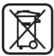
According to European Directive 2002/96/EC, measuring tools that are no longer usable, and according to European Directive 2006/66/EC, defective or exhausted batteries, must be collected separately and disposed of at an appropriate recycling facility. Do not dispose of them in household waste.
Subject to change without notice.
Serbian
Safety Instructions

All instructions must be read and observed. KEEP THESE INSTRUCTIONS IN A SAFE PLACE.
Have your measuring tool serviced by qualified personnel using only original replacement parts. This ensures that the safety of the measuring tool is maintained. Do not operate the measuring tool in explosive atmospheres, such as in the presence of flammable liquids, gases, or dust. Sparks may be generated in the measuring tool, which could ignite dust or fumes. The measuring tool may not guarantee 100% safety due to technological limitations. To eliminate hazards, before drilling, sawing, or milling into walls, ceilings, or floors, consult other information sources such as construction plans, construction phase photographs, etc. Weather influences, such as humidity in the air or proximity to other electrical devices, can adversely affect the accuracy of the measuring tool. The properties and condition of walls (e.g., moisture, metal-containing building materials, conductive wallpaper, materials such as dampers, tiles) as well as the number, type, size, and position of objects can falsify measurement results.
Dr. Egbert Schneider Senior Vice President Engineering
Dr. Eckerhard Strötgen
Head of Product
Certification

Robert Bosch GmbH, Power Tools Division
D-70745 Leinfelden-Echterdingen
Dr. Egbert Schneider Senior Vice President Engineering
Dr. Eckerhard Strötgen Head of Product Certification

Robert Bosch GmbH, Power Tools Division D-70745 Leinfelden-Echterdingen Leinfelden, 23.03.2011
Assembly
Installing/replacing the battery
When using the measuring tool, we recommend using alkaline manganese batteries.
Open the battery compartment cover 8 by first pressing the catch 9 in the direction of the arrow, then open the cover upwards. Insert the battery supplied. Observe the correct polarity, which is shown inside the compartment.
Dr. Egbert Schneider Senior Vice President Engineering
Dr. Eckerhard Ströttgen Head of Product Certification
i.v. M 1O 2 , yC
Robert Bosch GmbH, Power Tools Division D-70745 Leinfelden-Echterdingen Leinfelden, 23.03.2011
Montaža
Senior Vice President
Engineering
Dr. Eckerhard Strötgen
Head of Product
Certification
i.v. M 1O 7 y.cn
Robert Bosch GmbH, Power Tools Division
D-70745 Leinfelden-Echterdingen
Senior Vice President
Head of Product
Engineering
Certification

Robert Bosch GmbH, Power Tools Division
D-70745 Leinfelden-Echterdingen
Dr. Egbert Schneider Senior Vice President Engineering
Dr. Eckerhard Ströttgen Head of Product Certification

Robert Bosch GmbH, Power Tools Division D-70745 Leinfelden-Echterdingen Leinfelden, 23.03.2011
Assembly
Robert Bosch Korea Mechanics and Electronics Ltd.
Country
Figure T-10 298
: +82312704143/4148/4620
: +82312704144
Front and back view
[1]: +82312704680/4681/4682
: +82312704686
E-Mail: Bosch-pt.hotline@kr.bosch.com
Internet: www.bosch-pt.co.kr
Jalan Rawa Gelam III No. 2
Jakarta 13930
Indonesia
Tel.: +62 (21) 4683 25 22
Fax: +62 (21) 46828645/6823
E-Mail: sales@multitehaka.co.id
www.multitehaka.co.id
473 Dién Bién Phu
Phuong 25, Quan Binh Thanh
Thanh Pho Ho Chi Minh
Viet Nam
Tel.: +84 (8) 6258 3690 Ext 413
Fax: +84 (8) 6258 3692
hieu.lagia@vn.bosch.com
www.bosch-pt.com
Thai bo
Dung cu do, phu kien va bao bi thai duoc phan loai de tai che theo huong than thien voi moi truong.
Khong duoc thai bó dung cu do va pin/pin nap dien lai duoc vao chung voi rac sinh hoat!
Ducq quyen thay doi noi dung ma khong phai thong bao truc.
Therefore, it is equal to y = kx + b = 1.
Therefore, the area of triangle OBC is equal to the area of triangle COD plus the area of triangle BOC minus the area of triangle BOC.
Therefore b1 = 2, b2 = -4
Vector a = (x1, y1) points up, vector b = (x2, y2) points down.
1/3 1/3
Therefore the area of triangle OBC equals the area of triangle COD plus the area of triangle BOC minus the area of triangle BOC.
Therefore ab = 1
6 15 12 13 14 15 16 17 18 19 20 21 22 23 24 25 26 27 28 29 30 31 32 33 34 35 36 37 38 39 40 41 42 43 44 45 46 47 48 49 50
4.1234567890123456789012345678901234567890123456789012345678901234567890123456789012345678901234567890123456789
(B-A)
Therefore, the area of triangle OBC equals the area of triangle COD plus the area of triangle BOC.



- GMS 100 M PROFESSIONAL
- BOSCH
- GERMAN
- SAFETY INSTRUCTIONS
- PRODUCT DESCRIPTION AND SPECIFICATIONS
- INTENDED USE
- PRODUCT FEATURES
- DISPLAY ELEMENTS (SEE FIGURE A)
- TECHNICAL DATA
- DECLARATION OF CONFORMITY
- INSERTING/REPLACING THE BATTERY
- OPERATION
- INITIAL OPERATION
- SWITCHING ON AND OFF
- SWITCHING THE AUDIO SIGNAL ON/OFF
- METHOD OF OPERATION (SEE FIGURES A-B)
- MEASURING PROCEDURE
- METAL
- POWER CABLE
- NOTES
- WORKING ADVICE
- MARKING OBJECTS
- TEMPERATURE CONTROL
- WARNING FUNCTION
- RECALIBRATION
- MAINTENANCE AND SERVICE
- MAINTENANCE AND CLEANING
- AFTER-SALES SERVICE AND CUSTOMER ASSISTANCE
- WWW.BOSCH-PT.COM
- GREAT BRITAIN
- IRELAND
- AUSTRALIA, NEW ZEALAND AND PACIFIC ISLANDS
- REPUBLIC OF SOUTH AFRICA
- CUSTOMER SERVICE
- GAUTENG - BSC SERVICE CENTRE
- KZN - BSC SERVICE CENTRE
- WESTERN CAPE - BSC SERVICE CENTRE
- BOSCH HEADQUAR
- PEOPLE'S REPUBLIC OF CHINA
- CHINA MAINLAND
- HK AND MACAU SPECIAL ADMINISTRATIVE REGIONS
- INDONESIA
- PHILIPPINES
- MALAYSIA
- THAILAND
- SINGAPORE
- VIETNAM
- DISPOSAL
- ONLY FOR EC COUNTRIES
- FRANÇAIS
- MONTAGE
- ASSEMBLY
- WASTE DISPOSAL
- THE MEASURING TOOL IS INTENDED FOR THE DETECTION OF METAL AND METAL-CONTAINING OBJECTS AS WELL AS LIVE WIRES
- T01XIEIA E6EIEWV (BAEEIKOVA A)
- TEXVKA XAAPAKTNPOTUKA
- ΣΥΝΑΡΜΟΛΌΓΗΣΗ
- LIQUIDATION
- SWITCHING THE ACOUSTIC SIGNAL ON/OFF
- OPERATION (SEE FIGURES A-B)
- MEASUREMENT
- LARGE OBJECTS ARE DISPLAYED WITH THE RING LIGHTING UP AND THE SIGNAL SOUNDING OVER THE ENTIRE WIDTH
- CONDUCTIVE CABLE
- INSTRUCTIONS
- APPLICATION INSTRUCTIONS
- TEMPERATURE PRE-WARNING FUNCTION
- SERVICE AND CUSTOMER CONSULTATION
- REGION: RUSSIA, BELARUS, KAZAKHSTAN
- RUSSIA
- BELARUS
- KAZAKHSTAN
- UTILIZATION
- ONLY FOR EU COUNTRIES
- UKRAINIAN
- ONC NPOAYKTY I NOCAYR
- EKCNIYATAUIA
- TOUATOK PO60TU
- BMKAHHBMMKAHH
- BBIMKHEHHBBMKEHH3BYKOBORO CNHA
- OPERATING PRINCIPLE (SEE FIG. A-B)
- STEM GUIDE
- INDICATIONS
- OPERATING INSTRUCTIONS
- TURN ON THE MEASURING DEVICE AND, BEFORE TURNING IT OFF, ALLOW IT TO STABILIZE ITS TEMPERATURE
- FUNCTIONING
- CALIBRATION
- TECHNICAL SERVICE
- TECHNICAL SERVICE AND MAINTENANCE
- AFTER-SALES SERVICE AND CUSTOMER SERVICE
- UKRAINE
- EU DECLARATION OF CONFORMITY
- ROMÂNA
- SAFETY AND WORK INSTRUCTIONS
- OPERATING INSTRUCTIONS (SEE FIGURES A–B)
- THE DEVICE EMITS A SIGNAL WHEN IT DETECTS METAL AND AUDIO SIGNALIZATION
- LIVE CABLES
- INDICATION
- OPERATION INSTRUCTIONS
- MAINTENANCE SERVICE
- BEFORE USE, CHECK THE MEASURING DEVICE. IF YOU NOTICE ANY VISIBLE DAMAGE OR LOOSE PARTS INSIDE, DO NOT USE IT AS IT IS UNSAFE
- SERVICE AND CONSULTATION
- ROBERT BOSCH EOOD - BULGARIA
- SERBIAN
- INSTALLING/REPLACING THE BATTERY
- MONTAŽA
- COUNTRY
- FRONT AND BACK VIEW
- THAI BO
- THEREFORE, THE AREA OF TRIANGLE OBC IS EQUAL TO THE AREA OF TRIANGLE COD PLUS THE AREA OF TRIANGLE BOC MINUS THE AREA OF TRIANGLE BOC
- THEREFORE B1 = 2, B
- VECTOR A = (X1, Y1) POINTS UP, VECTOR B = (X2, Y2) POINTS DOWN
Brand : BOSCH
Model : GMS 100 M
Category : Detector