
TT 1800 E - Hand dryer Starmix - Free user manual and instructions
Find the device manual for free TT 1800 E Starmix in PDF.
| Product type | Warm air hand dryer |
| Brand | Starmix |
| Model | TT 1800 E |
| Nominal power | 1800 W |
| Heating power | 1700 W |
| Motor power | 100 W |
| Airflow rate | 38 l/s |
| Dimensions (W x D x H) | 270 x 161 x 330 mm |
| Weight (with wall bracket) | 3.2 kg |
| Power supply | Recessed socket or fixed connection |
| Protection | Fuse 16 A max. |
| Electronic timer | Duration: 32 seconds (model TT 1800 E: 4 minutes) |
| Proximity sensor | Infrared, contactless |
| Switching distance | Approx. 15 cm (hands) |
| Safety shutdown | Automatic after 4 minutes if sensor obstructed |
| Safety thermostat | Yes |
| Thermal fuse | Yes |
| Anti-theft device | Integrated into cover plate |
| Air intake grille | Clean with vacuum cleaner or brush |
| Installation | Wall mounting plate (plugs and screws provided) |
| Package contents | Unit, plugs, screws, network clamp, collars, safety key, screwdriver, scent diffuser |
| Standards | CCA, IP 23, CE |
Frequently Asked Questions - TT 1800 E Starmix
User questions about TT 1800 E Starmix
0 question about this device. Answer the ones you know or ask your own.
Ask a new question about this device
Download the instructions for your Hand dryer in PDF format for free! Find your manual TT 1800 E - Starmix and take your electronic device back in hand. On this page are published all the documents necessary for the use of your device. TT 1800 E by Starmix.
USER MANUAL TT 1800 E Starmix
natural_image
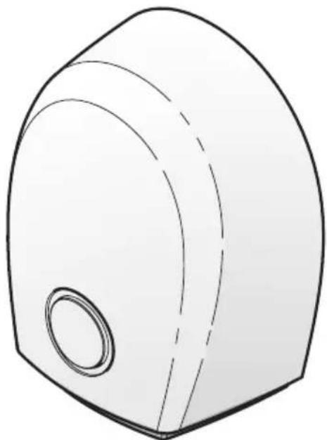
3D technical drawing of a mechanical component with a circular opening and curved top surface (no text or symbols)
Sicherheitsabstände

Sicherheitsabstände

Minimum distances


3e
D
| A | Thermal cut-out | H | Switch-off additional feature Active Oxygen / Scent | 3 | Flush socket | 10 | Connecting lead/installation |
| B | Thermal circuit breaker | I | Active Oxygen-generator / lifting magnet TT1800-EO/-ED | 4 | Predetermined breaking point | 11 | Terminal |
| C | Heating | X | Bath tub | 5 | Connecting lead device | 12 | Fixing holes |
| D | Motor | Y | Shower tray | 6 | Air intake grille | 13 | Scent insert |
| E | Micro switch TT1800, TTH1800 | Z | Shower head | 7 | Concealed wiring | 14 | Air outlet grille |
| F | LED TT1800E | 1 | Body surface/Anti-theft device | 8 | Strain relief clamp | ||
| G | Proximity control TT(H)1800EO, EF, E | 2 | Mounting plate/Wall bracket | 9 | Wire lead through |
F
TT1800, TT1800E, TTH1800, TTH1800E

natural_image
Technical line drawing of a mechanical component with multiple screw and bracket components (no text or symbols)TT1800, TT1800E, TTH1800, TTH1800E

For additional safety information, please refer to the minimum distance and safety notes chapters in these instructions.
We have compiled these operating instructions so that you become familiar with your new appliance quickly and comprehensively.
- Please read these instructions carefully before using this appliance. It provides you with important information on its safety, operation, maintenance and disposal.
- Familiarise yourself with your new appliance and its various functions following the sequence of the instructions.
- Follow all notes and explanations referring to the correct operation and handling. This will ensure the continuous availability and a long life for your appliance.
- The safety notes, in particular, must be followed. They help you to prevent accidents and to protect your appliance from damage..
- Please keep these instructions for future reference.
This appliance complies with the current state of technology and the applicable safety regulations for electrical appliances. The manufacturer will not accept any liability for damage caused by improper use or incorrect operation.
Included in delivery
1 hair and/or hand dryer
4 dowels
4 button head wood screws
1 terminal
2 countersunk flat head tapping screws for cover plate
2 strain relief clamps
4 slotted pan head screws for strain relief clamps
1 safety key
1 screw driver (with TT 1800 E only)
1 scent insert

natural_image
Technical line drawing of a mechanical component with multiple screw and nut assembly (no text or symbols)| Technical dataCCA IP 23 CE | Hot air hand dryer Hot air hair dryer | ||||||
| TT 1800 TT | 1800E TT 1800E | Active Oxygen | TT 1800E scent | TTH1800 TTH | 1800E | ||
| Rated output 1800 watts X | X X X X X | ||||||
| Rated output 1700 watts X | X X X X X | ||||||
| Motor output 100 watts X | X X X X | ||||||
| Air volume: 38 l/s X X X X | X X | ||||||
| Appliance dimensions w 270, d 161, h 330 mm | |||||||
| Weight incl. wall bracket: | [kg] | 3,2 | 3,2 | 3,5 | 3,5 | 3,2 | 3,2 |
| Features | Hot air hand dryer | Hot air hair dryer | ||||
| TT 1800 | TT 1800E | TT 1800E Active Oxygen | TT 1800E scent | TTH1800 | TTH1800E | |
| Electronic timer switch: time delay 32 sec. | X | |||||
| Electronic timer switch: time delay 4 mins. | X | |||||
| Electronic proximity switch | X | X | X | X | ||
| Safety mains plug connection | X | X | X | X | X | X |
| Safety temperature limiter | X | X | X | X | X | X |
| Thermal fuse | X | X | X | X | X | X |
| Safety cut-out sensor | X | X (4min) | X (4min) | X (10min) | ||
| Integrated mounting plate | X | X | X | X | X | X |
| Anti-theft cover plate | X | X | X | X | X | X |
| Air intake grille suitable for vacuum cleaning | X | X | X | X | X | X |
| Active oxygen | ||||||
| Scent dispensing cartridges | X | |||||
| LED light | X | X | X | |||
Installation instructions
The installation must be carried out by qualified personnel to ensure that the appliance is connected in accordance with safety regulations. In rooms with showers and bath tubs the appliance must be installed with the minimum distances laid down in the VDE regulations (0.6 mtrs (24 inches) from the edge of the shower and/or bath and 1.2 mtrs (48 inches) from a shower head).
Installation sequence
The maintenance-friendly installation concept
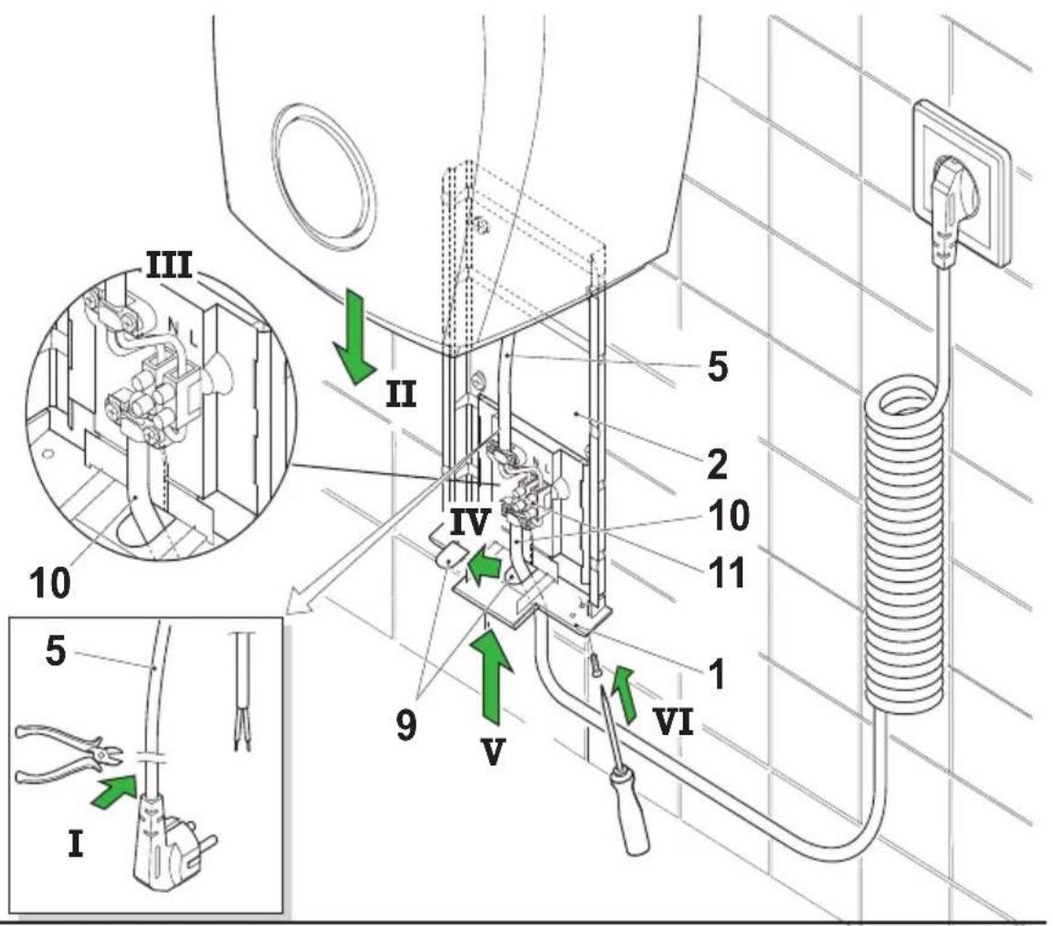
The TT1800 installation system enables simple, maintenance-friendly wall mounting without having to open up the appliance. For ease of installation, we have separated the appliance into two components: The installer installs a socket (or a permanent connection), screws the mounting plate on, slides the ready-to-use appliance onto it, inserts the mains plug into the socket (or connects), screws the anti-theft cover plate on – finished. It's as easy as that!
-
Pull the cover plate [1] (not screwed on) down and out of the appliance. Pull the mounting plate [2] which has been inserted at the back of the appliance downwards and out.
-
Confirm where the appliance is to be located, mark the 4 fixing holes [12], using mounting plate [2] as a template, drill the holes (8 mm ∅), insert the dowels and fix the mounting plate with the enclosed button-head wood screw A. We recommend mounting heights as shown in figures A, B or C. It must be ensured that the appliance is firmly secured to a solid wall.
-
There are 5 different ways to connect the appliance as described below.
a) Mounting via an installed flush socket. The upper part of the cover plate [1] is not required. Break it off at the predetermined breaking point [4]. When the mounting plate [2] has been fixed, push the appliance onto to the mounting plate from the top as shown in figure B, insert the plug into the socket [3] und push the appliance all the way down. Fasten the cover plate with the 2 enclosed countersunk flat head tapping screws.
b) Concealed wiring Connection via wiring concealed in the wall [7] (instead of a socket). Fix mounting plate [2] to wall as shown in fig. C. Slide the cover plate into the mounting plate from below and route the wiring from the wall through the opening in the cover plate. Insert the attached terminal [11]. Cut the plug at the connection lead [5] of the appliance, strip the cable and, squeeze the wire end ferrules on. Connect both lead as shown in fig. C. Ensure that L (brown) and N (blue) are connected correctly. Secure the connecting lead of the appliance with the enclosed strain-relief clamp [8]. Push appliance fully down onto the cover plate and screw in the 2 enclosed countersunk flat head tapping screws.
c) Surface mount wiring from above Break out the wiring lead through at the rear of the appliance, top centre. When the mounting plate [2] has been attached as shown in fig. C, route the surface mount wiring on the mounting plate down under the cover plate [1] and through the opening. Continue with the connection as described in the 2nd paragraph under B.
d) Surface mount wiring from below On the cover plate [1], bottom centre, break out the wiring lead through [9]. When the mounting plate [2] has been attached as shown in fig. C, route the surface mount wiring through the opening in the cover plate. Continue with the connection as described in the 2nd paragraph under B.
e) Connecting lead with plug. Connection to a nearby socket with a flexible connecting lead with plug. On the cover plate [1], bottom centre, break out the wiring lead through [9]. Slide the cover plate into the mounting plate from below. Insert the attached terminal [11]. Cut the plug at the connection lead [5] of the appliance, strip the cable and, squeeze the wire end ferrules on. Prepare the connecting lead with the plug in the same way and route through the opening in the cover plate. Connect both wires as shown in fig. C and secure with the enclosed strain relief clamps [8]. Push appliance fully down onto the cover plate and screw in the 2 enclosed countersunk flat head tapping screws.
The appliances are now operational.
Switching options
Operate electronic timer switch on TT 1800 and TTH 1800. The time delay for TT 1800 is 32 secs. and, for TT 1800 E, 4 mins.
The appliances will switch off automatically.
TT 1800 E, TTH 1800 E Active Oxygen / scent, TTH1800 E
The appliances are operated without touching via infrared proximity switches.
The switching distance (distance between the underside of the appliance and hands and/or head) is approx. 15 cm (6 inches) for the TT 1800 and approx. 40 cm (16 inches) for the TTH 1800 E. The switching sensitivity can be changed by a technician.
Safety cut-out sensor
TT 1800 E, TTH 1800 E
The integrated electronics prevent continuous operation if the infrared proximity switch has been covered, e.g. due to chewing gum vandalism
TT 1800 E-models will switch off after 4 mins and TTH 1800 E models after 10 mins. After the source of interference has been removed, the dryers are operational again.
Height adjustment for Starmix hair dryers
The attractive, robust Starmix THH500 / TTHH1800 height adjustment, order no. 19 07 09 makes it possible to adjust the hair dryer continuously and to the user's height.
This makes drying hair much easier, particularly for children and wheelchair users.
As an alternative to the height adjustment, two hair dryers can be mounted at different heights, 40 cms (16 inches) apart (range of the electronic infrared proximity switch 40 cm (16 inches) max.).

Cleaning and maintenance
Vacuum the air intake grille [6] at the underside of the appliance with the crevice nozzle of a vacuum cleaner to remove any lint and dust, if required. Remove any dirt that is stuck to the grille with a brush.

Safety notes
- Before connecting the appliance check that the voltage stated on the name plate corresponds with your mains voltage. The name plate is located on the underside of the enclosure.
- Fuse the appliance with 16 A max.
- Please note that improper use of electrical appliances can generate hazards which may not be recognised by children.
- Please make these operating instructions also available to other users of the appliance, so that they can learn about all the features and notes.
- carrying out any work or cleaning the appliance, make sure that it is isolated from the power supply!
Schéma électrique

TT1800, TT1800E, TTH1800, TTH1800E

natural_image
Technical line drawing of a mechanical component with multiple screw and bracket components (no text or symbols)TT1800, TT1800E, TTH1800, TTH1800E

natural_image
Technical line drawing of a mechanical component with multiple screw and nut assembly (no text or symbols)| Datos técnicosCCA IP 23 CE | Secadora de manos por aire caliente Secador de cabello por aire caliente | ||||||
| TT 1800 TT | 1800E TT 1800E | oxígenoactivo | TT 1800Eperfume | TTH1800 TTH | 1800E | ||
| Potencia nominal 1800 vatios X X X X X X | |||||||
| Potencia calorífica 1700 vatios X X X X X X | |||||||
| Potencia de motor 100 vatios X X X X X X | |||||||
| Corriente de aire 3 38 l/s X X X X | |||||||
| Dimensiones del aparato a 270, P 161, A 330 mm | |||||||
| Peso con soporte de pared | [kg] | 3,2 | 3,2 | 3,5 | 3,5 | 3,2 | 3,2 |
TT1800, TT1800E, TTH1800, TTH1800E

natural_image
Technical line drawing of a mechanical component with multiple screw and bracket components (no text or symbols)TT1800, TT1800E, TTH1800, TTH1800E

natural_image
Technical line drawing of a mechanical component with multiple screw and nut assembly (no text or symbols)TT1800, TT1800E, TTH1800, TTH1800E

natural_image
Technical line drawing of a mechanical component with multiple screw and nut assembly (no text or symbols)| Technische gegevens [IMAGE] [IMAGE] [IMAGE] [IMAGE] [IMAGE] [IMAGE] [IMAGE] [IMAGE] [IMAGE] [IMAGE] [IMAGE] [IMAGE] [IMAGE] [IMAGE] [IMAGE] [IMAGE] [IMAGE] [IMAGE] [IMAGE] [IMAGE] [IMAGE] [IMAGE] [IMAGE] [IMAGE] [IMAGE] [IMAGE] [IMAGE] [IMAGE] [IMAGE] [IMAGE] [IMAGE] [IMAGE] [IMAGE] [IMAGE] | Warmelucht haardroger Warmelucht haardroger | ||||||
| TT 1800 TT | 1800E TT 1800E | Ozon | TT 1800E Geur | TTH1800 TTH | 1800E | ||
| Nominaal vermogen 1800 Watt X X X X X X | |||||||
| Verwarmingsvermogen 1700 Watt X X X X X X | |||||||
| Motorvermogen 100 Watt X X X X X | |||||||
| Luchtstroom 38 l/s X X X X X X | |||||||
| Afmetingen toestel | B 270, D 161, H 330 mm | ||||||
| Gewicht met wandhouder : | [kg] | 3,2 | 3,2 | 3,5 | 3,5 | 3,2 | 3,2 |
TT1800, TT1800E, TTH1800, TTH1800E

natural_image
Technical line drawing of a mechanical component with multiple screw and bracket components (no text or symbols)TT1800, TT1800E, TTH1800, TTH1800E

natural_image
Technical line drawing of a mechanical component with multiple screw and nut assembly (no text or symbols)| Tekniska dataCCA IP 23 CE | Varmluftshandtork Varmluftshårtork | ||||||
| TT 1800 TT | 1800E TT 1800E | Aktiv syre | TT 1800E doft | TTH1800 TTH | 1800E | ||
| Märkeffekt 1800 Watt X X | X X X X | ||||||
| Värmeeffekt 1700 Watt X X | X X X X X | ||||||
| Motoreffekt 100 Watt X X | X X X X | ||||||
| Luftström 38 l/s X X X X X | X | ||||||
| Mått för apparaten | 270 (b), 161 (d), 330 (h) mm | ||||||
| Vikt med väggfäste : | [kg] | 3,2 | 3,2 | 3,5 | 3,5 | 3,2 | 3,2 |
TT1800, TT1800E, TTH1800, TTH1800E

For mer informasjon om sikkerhet kan du lese avsnittene sikkerhetsavstander og sikkerhetshenvisninger i denne veiledningen
natural_image
Technical line drawing of a mechanical component with multiple screw and nut parts (no text or symbols)| Tekniske DataCCA IP 23 CE | Varmluft-Händtørrer Varmluft-Hårtørret | ||||||
| TT 1800 TT | 1800E TT 1800E | Aktiv Surstoff | TT 1800EDurft | TTH1800 TTH | 1800E | ||
| Nominell effekt 1800 Watt | X X X X X X | ||||||
| Varmeeffekt 1700 Watt | X X X X X | ||||||
| Motoreffekt 100 Watt | X X X X X | ||||||
| Luftstrøm 38 l/s | X X X X X | ||||||
| Dimensjon apparat: | B 270, T 161, H 330 mm | ||||||
| Vekt med veggholder: | [kg] | 3,2 | 3,2 | 3,5 | 3,5 | 3,2 | 3,2 |
TT1800, TT1800E, TTH1800, TTH1800E

natural_image
Technical line drawing of a mechanical component with multiple screw and nut assembly (no text or symbols)TT1800, TT1800E, TTH1800, TTH1800E

natural_image
Technical line drawing of a mechanical component with multiple screw and nut assembly (no text or symbols)TT1800, TT1800E, TTH1800, TTH1800E

natural_image
Technical line drawing of a mechanical component with multiple screw and nut assembly (no text or symbols)TT1800, TT1800E, TTH1800, TTH1800E

natural_image
Technical line drawing of a mechanical component with multiple screw and bracket components (no text or symbols)TT1800, TT1800E, TTH1800, TTH1800E

natural_image
Technical line drawing of a mechanical component with multiple screw and nut assembly (no text or symbols)TT1800, TT1800E, TTH1800, TTH1800E

natural_image
Technical line drawing of a mechanical component with multiple screw and nut parts (no text or symbols)TT1800, TT1800E, TTH1800, TTH1800E

natural_image
Technical line drawing of a mechanical component with multiple screw and nut assembly (no text or symbols)TT1800, TT1800E, TTH1800, TTH1800E

natural_image
Technical line drawing of a mechanical component with multiple screw and bracket components (no text or symbols)TT1800, TT1800E, TTH1800, TTH1800E

natural_image
Technical line drawing of a mechanical component with multiple screw and nut assembly (no text or symbols)| Tehnični podatkiCCA IP 23 | Toplozračni sušilnik za roke Toplozračni sušilnik za lase | ||||||
| TT 1800 TT | 1800E TT 1800E | aktivnikisik | TT 1800Evonjava | TTH1800 TTH | 1800E | ||
| Nazivna moč 1800 Watt X X | X X X X | ||||||
| Grelna moč 1700 Watt X X X | X X X | ||||||
| Moč motorja 100 Watt X X X | X X X | ||||||
| Pretok zraka 38 l/s X X X X X | X X | ||||||
| Mere aparata: | širina 270 mm, globina 161 mm, višina 330 mm | ||||||
| Teža s stenskim nosilcem : | [kg] | 3,2 | 3,2 | 3,5 | 3,5 | 3,2 | 3,2 |
TT1800, TT1800E, TTH1800, TTH1800E

natural_image
Technical line drawing of a mechanical component with multiple screw and bracket components (no text or symbols)TT1800, TT1800E, TTH1800, TTH1800E

natural_image
Technical line drawing of a mechanical component with multiple screw and nut assembly (no text or symbols)TT1800, TT1800E, TTH1800, TTH1800E

natural_image
Technical line drawing of a mechanical component with multiple screw and bracket components (no text or symbols)TT1800, TT1800E, TTH1800, TTH1800E

natural_image
Technical line drawing of a mechanical component with multiple screw and nut assembly (no text or symbols)TT1800, TT1800E, TTH1800, TTH1800E
natural_image
Technical line drawing of a mechanical component with multiple screw and bracket components (no text or symbols)TT1800, TT1800E, TTH1800, TTH1800E

natural_image
Technical line drawing of a mechanical component with multiple screw and nut assembly (no text or symbols)TT 1800E, TTH 1800 E 活性氧/喷香, TTH 1800E
这些机器装有红外线电子感应式开关。
感应距离(手或头部与机器下端的距离)
TT 1800 约15CM
TTH 1800 E 约40CM
感应距离可由专业人员调整。
传感器-安全关机
TT 1800E, TTH 1800 E


- Sicherheitsabstände
- Included in delivery
- Installation instructions
- Installation sequence
- The maintenance-friendly installation concept
- Switching options
- TT 1800 E, TTH 1800 E Active Oxygen / scent, TTH1800 E
- Safety cut-out sensor
- TT 1800 E, TTH 1800 E
- Height adjustment for Starmix hair dryers
- Cleaning and maintenance
- Safety notes
- Schéma électrique
- 传感器-安全关机
Brand : Starmix
Model : TT 1800 E
Category : Hand dryer