
T-C BL HEPA - Hand dryer Starmix - Free user manual and instructions
Find the device manual for free T-C BL HEPA Starmix in PDF.

| Product type | Automatic touchless hand dryer |
| Brand | Starmix |
| Model | T-C BL HEPA |
| Supply voltage | AC 220-240 V (50 Hz) / AC 110-120 V (60 Hz) |
| Power (standard mode) | 320 W (heating off) / 720 W (heating on) |
| Power (silent mode) | 130 W (heating off) / 530 W (heating on) |
| Power (sterilization mode) | 12 W (PEBBLE PLUS model only) |
| Motor type | Brushless DC motor, 30,000 rpm |
| Maximum air speed | 96 m/s |
| Drying time | 10 to 12 seconds |
| Sensor type | Automatic touchless infrared, range 10-20 cm, angle 45° |
| Automatic shutoff | 50 seconds |
| Protection rating | IPX3 (drip-proof) |
| Insulation class | Class I |
| Dimensions (H x W x D) | 322.1 x 270.5 x 144.6 mm |
| Filter type | HEPA, lifespan ~60,000 cycles |
| UV-C lamp | Sterilization option (PEBBLE PLUS model), lifespan 3 years |
| Sterilization function | Built-in (on selected models) |
| LED indicator | Indicates operating status and filter alert |
| Installation | Wall-mounted, recommended height based on user |
| Cleaning | Soft damp cloth, no abrasive products |
Frequently Asked Questions - T-C BL HEPA Starmix
User questions about T-C BL HEPA Starmix
0 question about this device. Answer the ones you know or ask your own.
Ask a new question about this device
Download the instructions for your Hand dryer in PDF format for free! Find your manual T-C BL HEPA - Starmix and take your electronic device back in hand. On this page are published all the documents necessary for the use of your device. T-C BL HEPA by Starmix.
USER MANUAL T-C BL HEPA Starmix
Instruction manual
Bedienungsanleitung
natural_image
Simple line drawing of a circular object with a small protrusion at the bottom (no text or symbols)EN 03
DE 11
ES 19
FR 27
NL 35
PL 43
RU 51
CN 59
TECHNICAL SPECIFICATIONS
| Item Category | Performance Data | ||
| Operating Voltage | AC 220~240 V, 50 Hz / AC 110~120, 60Hz | ||
| Power | Standard mode | 220~240 V | 320 W (Heater off)/ 720 W (Heater on) |
| 110~120 V 320 W | (Heater off)/ 820 W (Heater on) | ||
| Quiet mode | 220~240 V | Q mode 'ON', 130 W(Heater off) / 530 W (Heater on) | |
| 110~120 V | Q mode 'ON', 130 W(Heater off) / 630 W (Heater on) | ||
| Sterilization mode(Applicable only for PEBBLE PLUS model) | Power 12W | ||
| Operating cycle 1 | hour on, 1 hour off | ||
| Air speed 17m/s | |||
| Standby Power | ≤0.5 W | ||
| Air Speed (sensing max) | 96 m/s | ||
| Motor Type | Brushless DC Motor, 30,000 RPM | ||
| Sensor Type | Auto Infrared touch free operation | ||
| Sensor Range | 45° 10~20cm | ||
| Timing Protection | 50 seconds auto shut off | ||
| Drying Time | 10 ~ 12 sec | ||
| Drip Proof | IPX3 | ||
| Isolation | CLASS I | ||
| Unit Size | H 322.1mm x W 270.5mm x D 144.6mm | ||
IMPORTANT SAFETY INSTRUCTIONS

WARNING – TO REDUCE THE RISK OF FIRE, ELECTRIC SHOCK, OR INJURY TO PERSONS OBSERVE THE FOLLOWING:
- Use this unit only in the manner intended by the manufacturer. The manufacturer is not responsible for any damages caused by misuse or defective installation.
- The instructions contained within the installation Template must be followed carefully when installing this unit. Failure to accurately follow the instructions may result in the incorrect operation of this unit, damage to property and/or personal injury.
- Installation work and electrical wiring must be done by qualified person(s) in accordance with all applicable codes and standards, including fire-rated construction.
- When cutting or drilling into wall or ceiling, do not damage electrical wiring and other hidden utilities.
- This unit must be powered by a dedicated circuit branch protected by a circuit breaker with the appropriate rating. Circuit cable must be fit current consumption for this unit.
- This unit has been designed for indoor use only, protect from water, sun and extreme temperatures, do not install it outdoors or close to moisture and heat generators.
- This unit can only be revised, maintained, repaired and removed by qualified person(s). If the unit stops and works strangely, contact your regional dealer or contractor.
- This appliance can be used by children aged from 8 years and above and persons with reduced physical, sensory or mental capabilities or lack of experience and knowledge if they have been given supervision or instruction concerning use of the appliance in a safe way and understand the hazards involved. Do not allow children to play with the appliance or carry out cleaning and user maintenance on this hand dryer.
- If the supply cord is damaged, it must be replaced by the manufacturer, its service agent or similarly qualified persons in order to avoid a hazard.
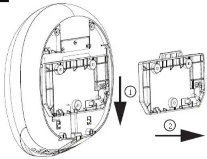
- The dryer cover can only be removed once the dryer has been disconnected from the docking station power source. To do this, please follow the sequence detailed in fig.8, ensuring the cover retaining screw positioned in the rear of the dryer is unscrewed. Reverse sequence to re-fit cover and dryer to the docking station power source.
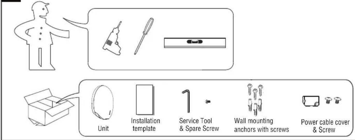
UNPACKING
- Remove all packing material. Recycling is recommended.
- Carefully remove the hand dryer from the shipping carton, using care not to drop the appliance.
- Inspect carefully for any damage that may have occurred during transit. Check for any loose, missing or damaged parts. If the hand dryer is damaged, promptly inform the shipper or dealer where you purchased it.
Standard items with the hand dryer are shown in Fig.1 together with tools need by the installer.
1
INSTALLATION
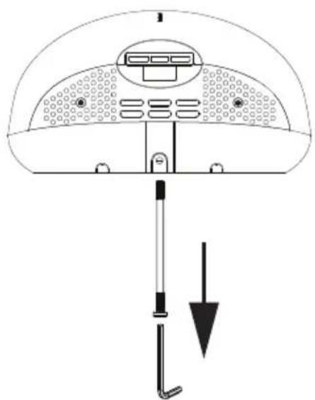
1. Wall bracket removal
1.1 Place the appliance on a cloth to avoid marking its surface.
1.2 Remove the one security screw seated on the bottom surface of the unit, using the service tool (fig.2).
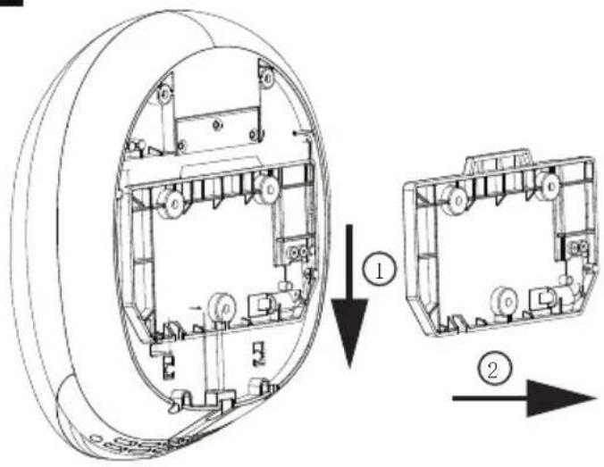
1.3 Pull down the wall mounting bracket and remove from the unit (fig.3).
2
natural_image
Diagram of a device interior with labeled components and directional arrow (no text or symbols)3
CAUTION
• Make sure power supply breaker is switched off.
- Check that the electrical supply corresponds to that shown on the rating plate. If the unit is connected to any electrical supply other than stated on the rating plate of the unit, permanent damage or unsafe operation of the unit may result.
- The unit must be mounted on a flat vertical wall capable of supporting the full weight of the unit.
2. Positioning
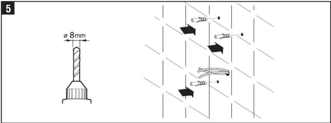
2.1 Mark the location on the wall with a pencil. Use the Installation Template to mark the locations for the three fixing points (fig. 4).
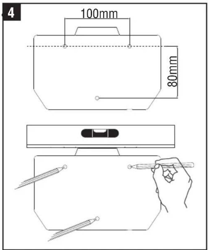
Recommended height measurements form the floor to top screws
| Installation target | Height |
| Adult male | 1400mm |
| Adult female | 1365mm |
| Children 5-8 years old | 1028mm |
| Children 8-11 years old | 1128mm |
| Children 11-14 years old | 1208mm |
| Wheelchair user | 1150mm |
2.2 Pre-drill the wall in the marked locations using 5/16" (8mm) drill, insert the plastic anchors and tap flush to the wall. If the cable entry is to be done from the wall provide a proper cable exit (fig. 5)
When installing above any surface, the distance from the bottom of the dryer must be a minimum of 700mm.
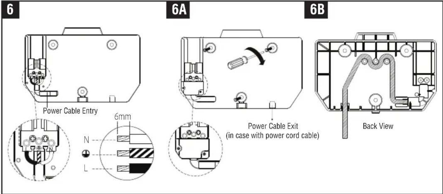
3. Installing Power cable & Connection terminal block
WARNING: ENSURE POWER NOT CONNECTED
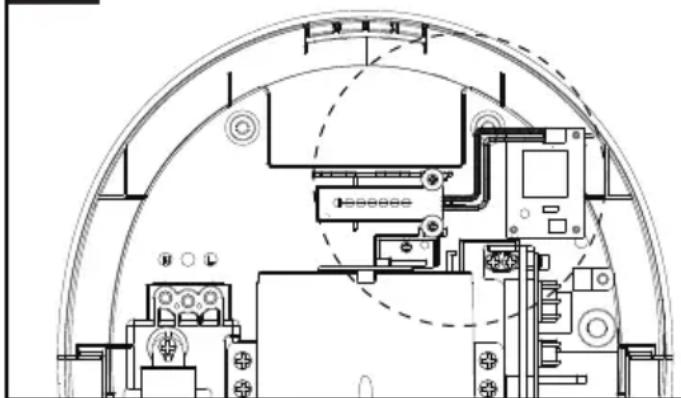
3.1 Pull the cable through the hole in the wall mounting bracket. Ensure the cable is long enough to route correctly through the wall mounting bracket to the terminal block (fig. 6).
3.2 The cable must sit in the dedicated channel. If the cable come through Power cable entry from outside, It is recommended that the cable is routed via the 3 bosses as in fig. 6B.
3.3 As shown, connect cable to terminal block.
3.4 Screw in terminal block.
3.5 Fix the wall mounting bracket to the wall. Screw to the wall using the appropriate fitting (fig 6A).
3.6 Fix the cable cover with screw on the wall mounting bracket.
CAUTION: Connect the ground wire to the terminal block marked “💡” The earth/ground cable must be fitted in all installations. Do not over-tighten and crush the power cable.
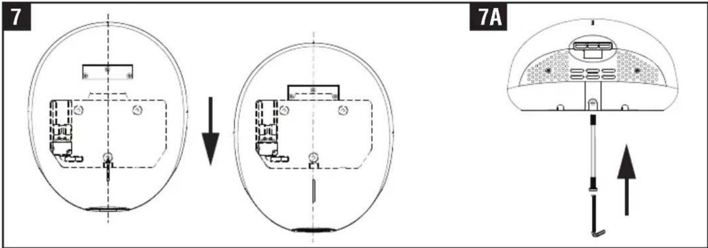
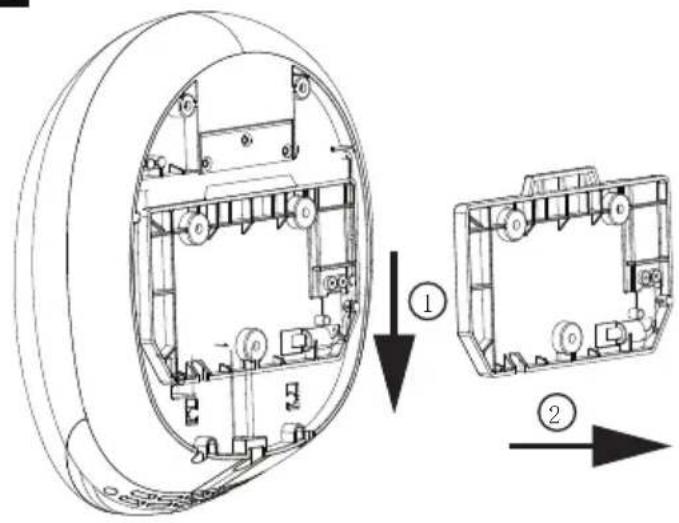
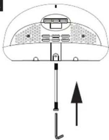
4. Fix the Main unit to Wall mounting bracket
4.1 Position the unit centrally above the wall mounting bracket so the metal bracket on the rear is positioned over the mating part of the wall bracket moulding. Keeping the dryer firmly against the wall, slowly slide the dryer down until there is no further travel. The dryer should then be electrically connected (fig 7).
4.2 Test the unit for correct operation. The LED light on the cover should flash 3 times with a red light after the power supply has been correctly connected and followed by continuous light white LED.
4.3 Insert and tighten the security screw seated on the bottom surface (fig 7A).
4.4 Cable from the spur to the docking station via the restraining spigots must not have excess length, to ensure cable restraint is effective. As shown in Fig 6B.
Note. If the LED light remains off, the unit must be refitted correctly.
HEATER SWITCH, QUIET (Q) MODE SWITCH & AIR STERILIZATION (S) MODE
- Remove the one security screw seated on the bottom surface from the unit, using the service tool (fig. 2).
- Lift the unit off the wall mounting bracket.
Note: Ensure the LED light on the front of the unit is OFF before opening the front cover, if the LED light is still ON, wait until the light goes off.
The unit has a built in UV-C lamp, avoid exposure to direct germicidal UV rays.

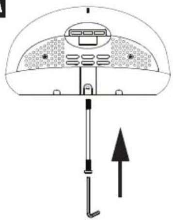
- Unscrew the two security screws from the bottom of the unit using the service tool provided (fig. 8), ensuring that the screws remain within the channel. Please note these screws are designed to remain captive within the channel.
- Remove the (1) screw from back of unit, using the + screw driver (fig 8A).
- Lift the front cover off the unit (fig. 9\~9A).
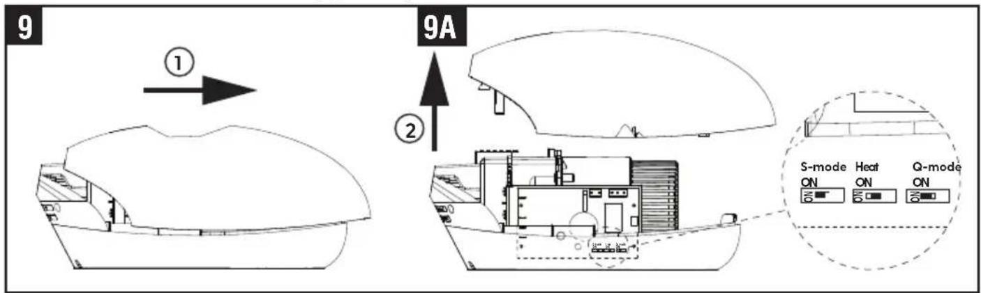
- To turn on/off heater, use the middle switch shown in fig. 9A. (Factory setting : ON)
- To change Quiet mode, use the right hand switch shown in fig. 9A. (Factory setting : OFF)
- To turn on/off on Air sterilization mode, use the left hand switch shown in fig. 9A. (Factory setting : OFF)
ATTACHING UNIT
Reposition the front cover on the unit.
Refix the 2 cover security screws into the bottom of the front cover (fig. 8).
Refix the cover screw situated in the base of the dryer (fig. 8A)
Reposition the unit on the wall mounting bracket and insert and tighten one security screw into the bottom of front cover (fig. 7\~7A).
Test the unit for correct operation. The LED light on the cover should flash 3 times with a red light after the power supply has been correctly connected and followed by continuous light white LED.
Note: If the LED light remains off, the unit must be refitted correctly.
FILTER & UV-C LAMP REPLACING
If the LED light on the front of the unit flashes red then the filter if fitted needs to be changed. The filter functions for approximately 60,000 operations.
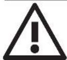
- Remove the one security screw from the middle of the bottom face of the unit (fig.2).
- Lift the unit off the TERRA4 wall mounting bracket (fig. 8).
- Remove the (2) security screws from the unit, using the service tool (fig. 8A).
- Remove the (1) screw from back of unit, using the + screw driver (fig 8B).
- Lift the front cover off the unit (fig. 9).
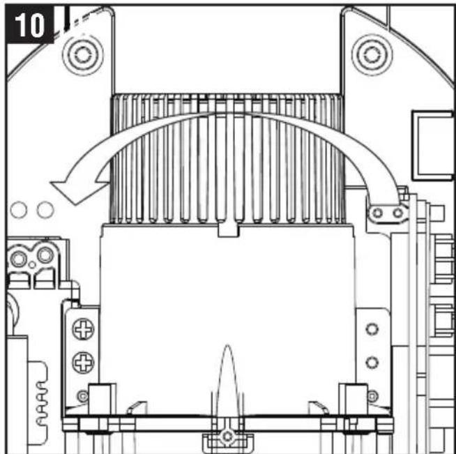
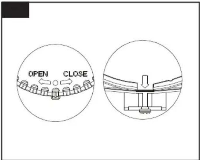
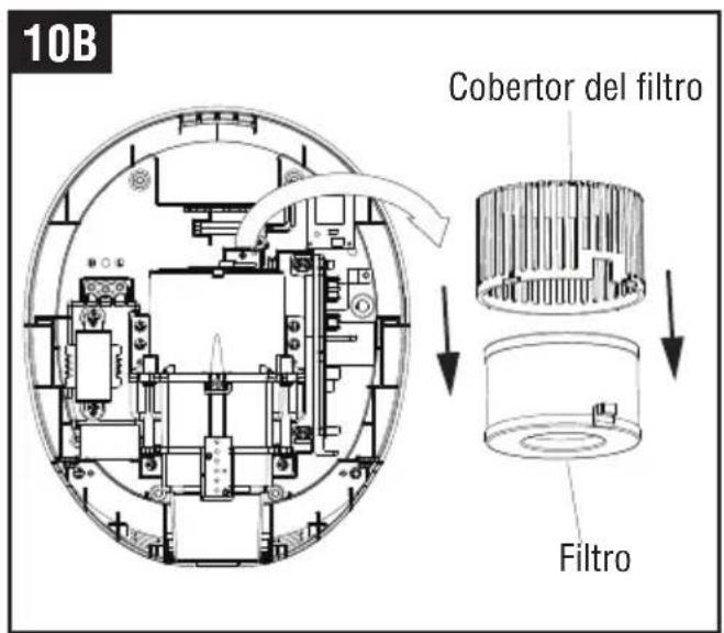
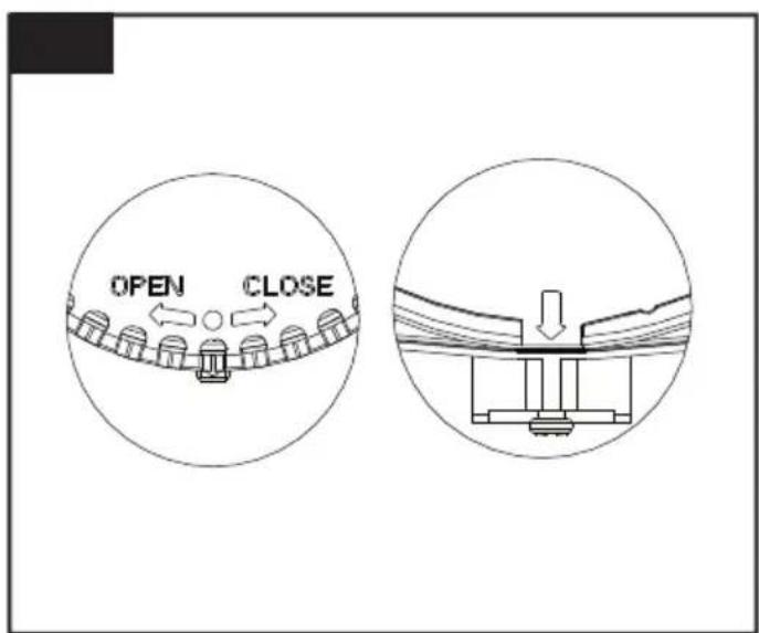
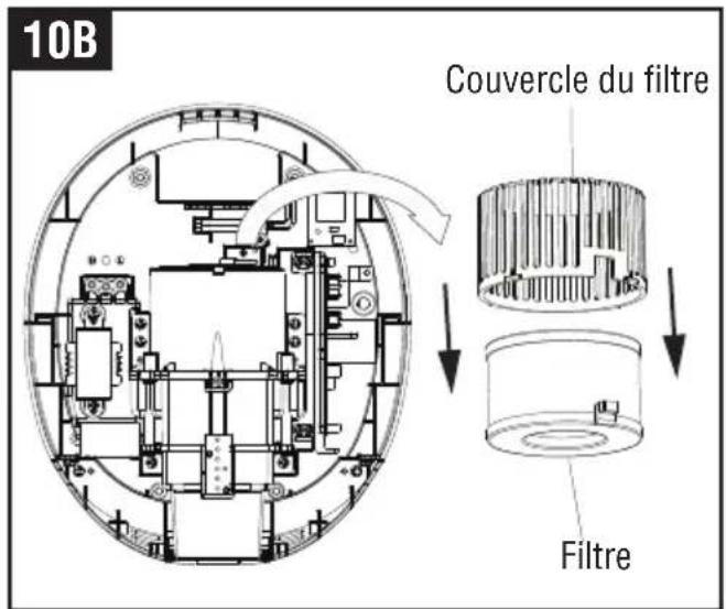
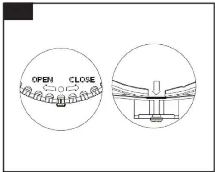
- Turn the filter cover to open direction (fig. 10).
The dot is aligned with the arrow present on the motor cover (fig. 10A).
Note: Ensure the LED light on the front of the Unit is OFF before opening the front cover, if the LED light is still ON, wait until the light goes off.
natural_image
Technical line drawing of a mechanical assembly with no visible text or symbols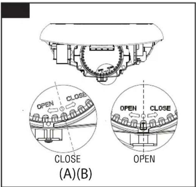
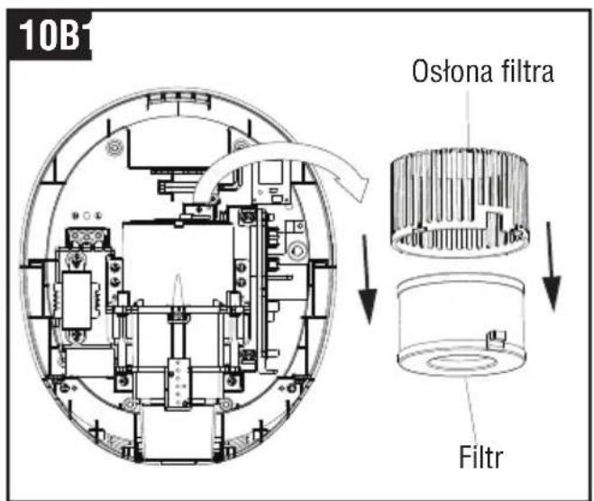
- Remove the filter(fig. 10B).
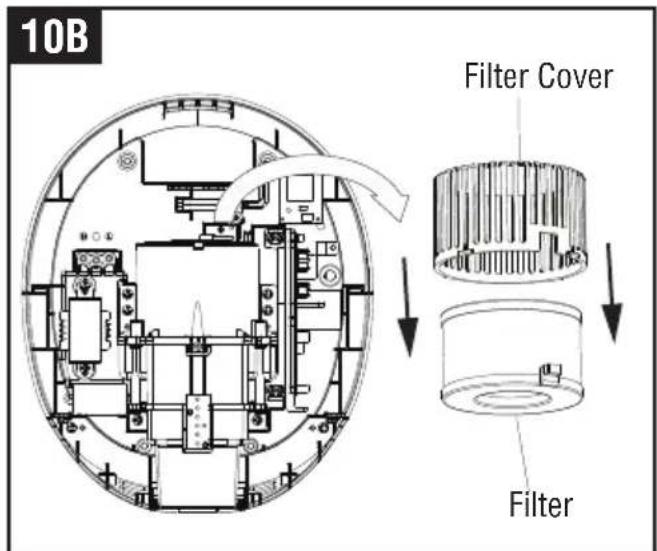
- Insert the New filter.
The dot on the filter cover is aligned with the arrow on the motor cover (fig.10C).
- Turn the filter cover to close direction. The dot is positioned to the right of the arrow on the motor cover (fig.10A-A).
WARNING - If the dryer has been fitted with a filter, it will need to be replaced after 60,000 operations but will continue working for a further 15,000 operations but without the benefits of the HEPA filter. At approximately 75,000 operations the red LED will be flashing on the window positioned at the front of the cover and the unit will stop working until a replacement filter is fitted.
11
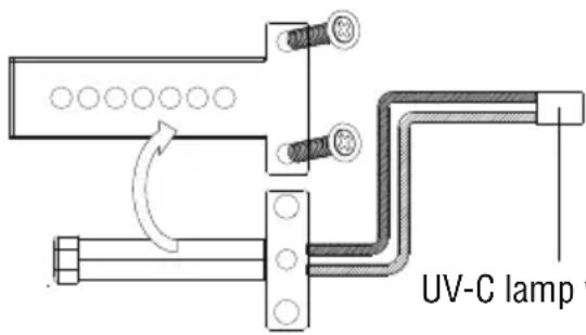
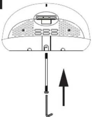
UV-C lamp wire jack
The sterilization function of UV-C lamp will be weakened after 3 years use, the UV-C lamp needs to be replaced for maintaining proper function. (Applicable only for PEBBLE PLUS model which is equipped Air sterilizer option)
- Remove the filter cover and filter shown in page 8.
- Remove the two screws on the UV-C lamp cover and remove UV-C lamp cover and pull out the UV-C lamp wire jack from the UV light board.(fig.11).
- Insert the New UV-C lamp and replace the UV-C lamp cover tighten the two screws and replace the wire jack on the UV-C lamp board.
ATTACHING UNIT
Replace the filter (shown in Page 8) and attaching unit on the wall mounting bracket (Shown in Page 7).
Note: On power up should the red LED continue to flash this means the filter is not fitted correctly and needs to be refitted.
OPERATING LED LIGHT
LED Lighting for standard and Black Edition
| Front Cover color Stand by Mode Working Mode Sterilization mode | |
| White / Silver White LED ON White LED fast mode White LED slow mode | |
| Black Edition Red LED ON Red LED fast mode Red LED slow mode |
Filter Alert Lighting
| Filter uses Light | Stanby / Sterilization mode | working mode (sensing mode) | |
| From 60,000 uses ~74,999uses | White LED | White LED ON / White LED slow mode | White LED ON fast mode |
| Red LED Red LED flashing OFF | |||
| Location LED (blue) OFF | ON | ||
| 75,000 uses ~until replace new filter | White LED | White LED ON slow mode | White LED ON slow mode |
| Red LED Red LED flashing | Red LED flashing | ||
| Location LED (blue) OFF | Flashing | ||
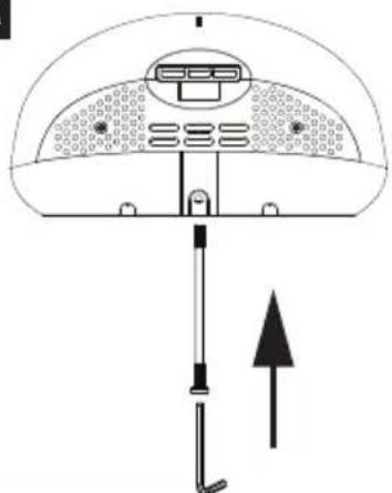
USE
- No touch operation.
- Shake excess water from hands.
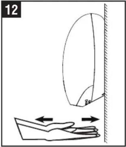
- Place hands under the outlet to start operation (fig. 12).
- Slowly move hands back and forth under the outlet at the bottom of the dryer.
- The blue hand location LED situated by the dryer outlet starts with the drying operation.
- The dryer and blue LED stops when the hands are removed.
- Hand dryer also auto shuts off after 50 seconds of uninterrupted use. If there is an electrical or motor problem, the blue LED will flash when hands off the placed under the dryer outlet.
The sterilization function turns on and off automatically
natural_image
Diagram showing a hand holding a curved object above a wall, with arrows indicating motion or force direction (no text or symbols)MAINTENANCE AND CLEANING
Lift the Unit off the wall mounting bracket before maintenance or repair.
13
natural_image
Illustration showing hands cleaning a circular object and inspecting a device with a brush (no text or symbols)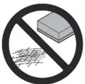
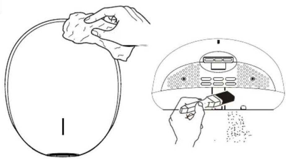
Regular maintenance
Regularly clean the outer casing use a soft, damp cloth to gently wipe away any dirt.
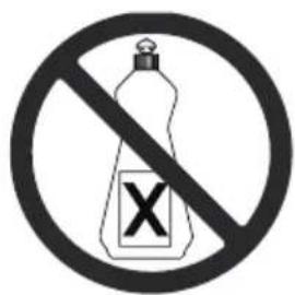
CAUTION: Never use abrasives or chemicals to clean the cover. Do not soak.
Periodical deep clean
- Clean and maintenance must not taken until the unit has been removed from the wall mounting bracket or cut off power.
- Use the service tool or security hex driver to remove the two cover security screw.
- Remove the cover.
- Clean all dust and lint from the interior of the hand dryer.
- Replace the cover.
- Wipe the cover with a damp cloth.
natural_image
Diagram of a device interior with a handle and arrow indicating downward movement (no text or symbols)3

ACHTUNG
natural_image
Cross-sectional diagram of a mechanical or electrical component with internal components and no visible text or symbolsnatural_image
Technical line drawing of a mechanical assembly with no visible text or symbolsnatural_image
Architectural floor plan showing room layouts and equipment layout (no text or labels)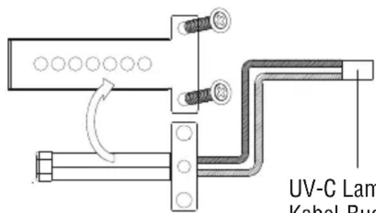
natural_image
Diagram showing a hand holding a curved object above a wall, with arrows indicating motion or force direction (no text or symbols)natural_image
Diagram of a device interior with labeled components and directional arrow (no text or symbols)3
PRECAUCIÓN
7A
natural_image
Diagram of a device with a dome-shaped top and vertical connectors, showing no text or symbols.natural_image
Technical line drawing of a mechanical assembly with no visible text or symbols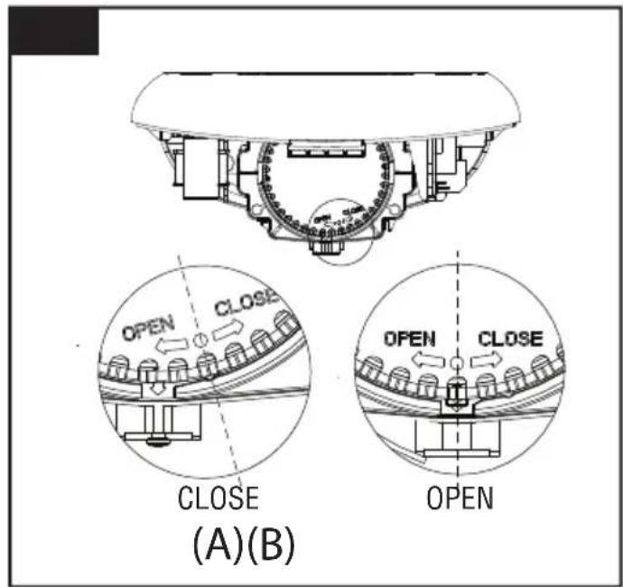
- Remueva el filtro(fig.10B).NOTA: "CLOSE": CERRADO, "OPEN": ABIERTO
natural_image
Technical line drawing of a mechanical assembly inside a circular housing (no text or symbols)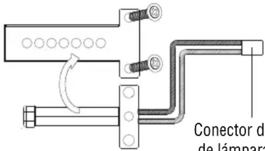
natural_image
Diagram showing a hand holding a curved object above a wall, with arrows indicating motion or force direction (no text or symbols)natural_image
Diagram of a device interior with a handle and arrow indicating direction (no text or symbols)3

ATTENTION
7A
natural_image
Diagram of a device with a dome-shaped top and vertical connectors, showing an upward arrow (no text or symbols)INTERRUPTEUR DU CHAUFFAGE, INTERRUPTEUR DU MODE SILENCIEUX (Q) ET INTERRUPTEUR DU MODE DE STÉRILISATION À L'AIR (S)
natural_image
Technical line drawing of a mechanical assembly with internal components and directional arrows (no text or symbols)- Retirez le filtre (fig. 10B).

natural_image
Technical line drawing of a mechanical assembly inside a dome-shaped enclosure, showing internal components and no text or symbols.
natural_image
Diagram showing a hand reaching toward a wall-mounted device with directional arrows indicating motion (no text or symbols)ENTRETIEN ET NETTOYAGE
Nettoyage régulier
natural_image
Diagram of a mechanical device with a downward arrow indicating force or direction (no text or symbols present)3

WAARSCHUWING
natural_image
Diagram showing a mechanical assembly before and after a transformation, with no visible text or symbols.7A
natural_image
Diagram of a device with a dome-shaped top and vertical rod, showing internal components and an upward arrow (no text or symbols)VERWARMINGSCHAKELAAR, STILLE (Q) MODUSSCHAKELAAR & LUCHT STERILISATIE (S) MODUS SCHAKELAAR
natural_image
Technical line drawing of a mechanical assembly with internal components and directional arrows (no text or symbols)
natural_image
Diagram showing a hand reaching toward a wall-mounted mirror, with arrows indicating motion direction (no text or symbols)ONDERHOUD EN REINIGING
Normaal onderhoud
natural_image
Diagram of a device with a dome-shaped top and vertical connectors, showing internal components and a downward arrow (no text or symbols)3

UWAGA
natural_image
Diagram of a device with a dome-shaped top and vertical connectors, showing an upward arrow (no text or symbols)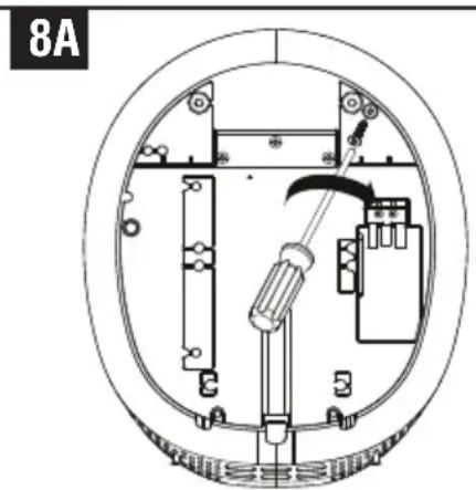
natural_image
Technical diagram of a circular mechanical or electrical component with internal components and no visible text or symbolsWYMIANA FILTRA I LAMY UV-C
natural_image
Technical line drawing of a mechanical assembly with internal components and directional arrows (no text or symbols)
- Usuń filtr (rys. 10B).
Filter Alert Lighting
natural_image
Diagram showing a hand holding a curved object above a wall, with arrows indicating motion or force direction (no text or symbols)KONSERWACJA I CZYSZCZENIE
natural_image
Diagram of a mechanical device with a downward arrow indicating force or movement (no text or symbols present)3
ОСТОРОЖНО
7A
natural_image
Diagram of a mechanical device with a dome-shaped top and vertical rod, showing internal components and an upward arrow (no text or symbols)natural_image
Technical line drawing of a mechanical assembly with internal components and directional arrows (no text or symbols)
natural_image
Technical schematic of an electronic device enclosed in a dome-shaped frame, showing internal components and wiring (no text or labels)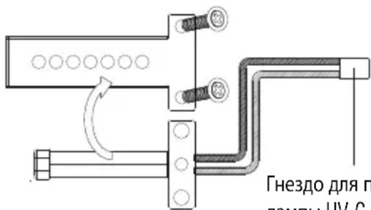
natural_image
Diagram showing a hand reaching toward a wall-mounted mirror, with arrows indicating motion direction (no text or symbols)natural_image
Diagram of a mechanical device with a downward arrow indicating force or movement (no text or symbols present)3

注意
从安装地面到顶部螺钉的推荐高度:
natural_image
Technical line drawing of a mechanical assembly with internal components and directional arrows (no text or symbols)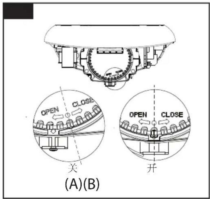
- 取下过滤器(图10B)。
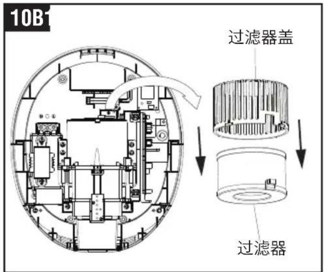
- 装上新过滤器。
natural_image
Diagram showing a hand holding a curved object above a wall, with arrows indicating motion or force direction (no text or symbols)维护与清理
定期维护
Type / Type designation
T-C BL HEPA
"DIRECTIVE OF THE EUROPEAN PARLIAMENT AND OF THE COUNCIL on the harmonization of the laws of the Member States relating to electromagnetic compatibility"
EN 55014-1:2017/A11:2020
EN 55014-2:2015
EN IEC 61000-3-2:2019
EN 61000-3-3:2013/A1:2019
ROHS 2011/65/EU, EU 2015/863
EN 50581:2012
Ebersbach / Fils 06.07.2021


- IMPORTANT SAFETY INSTRUCTIONS
- WARNING – TO REDUCE THE RISK OF FIRE, ELECTRIC SHOCK, OR INJURY TO PERSONS OBSERVE THE FOLLOWING:
- UNPACKING
- INSTALLATION
- Wall bracket removal
- CAUTION
- Positioning
- Installing Power cable & Connection terminal block
- Fix the Main unit to Wall mounting bracket
- HEATER SWITCH, QUIET (Q) MODE SWITCH & AIR STERILIZATION (S) MODE
- ATTACHING UNIT
- FILTER & UV-C LAMP REPLACING
- OPERATING LED LIGHT
- USE
- MAINTENANCE AND CLEANING
- Regular maintenance
- Periodical deep clean
- ACHTUNG
- PRECAUCIÓN
- ATTENTION
- INTERRUPTEUR DU CHAUFFAGE, INTERRUPTEUR DU MODE SILENCIEUX (Q) ET INTERRUPTEUR DU MODE DE STÉRILISATION À L'AIR (S)
- ENTRETIEN ET NETTOYAGE
- Nettoyage régulier
- WAARSCHUWING
- VERWARMINGSCHAKELAAR, STILLE (Q) MODUSSCHAKELAAR & LUCHT STERILISATIE (S) MODUS SCHAKELAAR
- ONDERHOUD EN REINIGING
- Normaal onderhoud
- UWAGA
- WYMIANA FILTRA I LAMY UV-C
- KONSERWACJA I CZYSZCZENIE
- ОСТОРОЖНО
- 注意
- 维护与清理
- 定期维护
Brand : Starmix
Model : T-C BL HEPA
Category : Hand dryer