
XT 1001 Mw - Hand dryer Starmix - Free user manual and instructions
Find the device manual for free XT 1001 Mw Starmix in PDF.

| Brand | Starmix |
| Model | XT 1001 Mw |
| Product type | Automatic infrared hand dryer |
| Power supply | 220-240 V, 50/60 Hz, 800-880 W |
| Standby power | Less than 1.5 W |
| Drying time | Less than 10-15 seconds |
| Airflow | 64-92 m³/h (38-54 CFM) |
| Air velocity | 56.5-81.8 m/s at 25 °C |
| Outlet temperature | 55 °C above ambient temperature |
| Motor type | Brushless, 200-450 W, 20,000-28,000 rpm |
| Heating element | 450 W (switchable) |
| Thermal protection | Auto-reset thermostat at 85 °C, thermal fuse at 142 °C |
| Sensor range | 200 mm ±20 mm, adjustable |
| Automatic shut-off | After 60 seconds |
| Protection class | IPX1 |
| Insulation class | Class 1 |
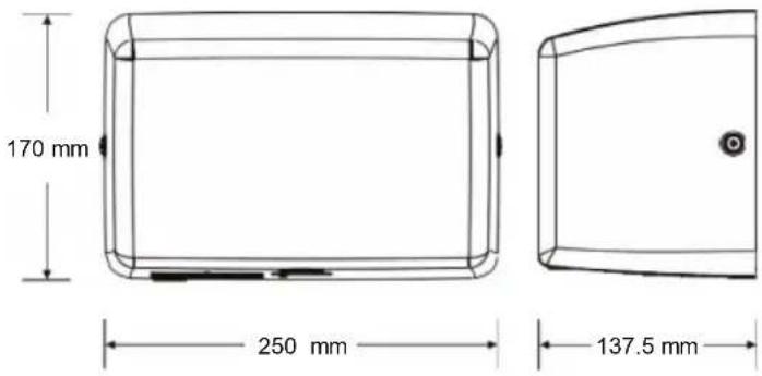
| Dimensions (W x H x D) | 170 x 250 x 137.5 mm (approx.) |
| Net weight | 3.8 kg |
| Color | White (standard) |
| Installation | By a qualified technician, wiring 1.5 mm², grounding mandatory |
| Filter | HEPA, replace every 6 months |
| Cleaning | Disconnect, remove the cover, clean the interior, do not immerse |
| Operation | Contactless, automatic infrared detection |
| Recommended mounting heights | Men: 1270 mm, Women: 1194 mm, Children 4-7 years: 889 mm |
| Wheelchair accessible | 1016 mm from floor |
Frequently Asked Questions - XT 1001 Mw Starmix
User questions about XT 1001 Mw Starmix
0 question about this device. Answer the ones you know or ask your own.
Ask a new question about this device
Download the instructions for your Hand dryer in PDF format for free! Find your manual XT 1001 Mw - Starmix and take your electronic device back in hand. On this page are published all the documents necessary for the use of your device. XT 1001 Mw by Starmix.
USER MANUAL XT 1001 Mw Starmix
450 W, On: 450 W, off: 0 W
natural_image
Technical line drawing of a mechanical or electrical component with no visible text or symbolsnatural_image
Technical line drawing of a mechanical device with directional arrows indicating motion (no text or symbols)Anschlüsse:
natural_image
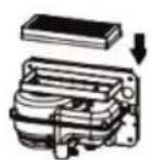
Three identical wireframe rectangular frames with a hand holding a small object, no text or symbols present.Betrieb
natural_image
Simple line drawing of a rectangular box with an upward arrow and a small circular mark below, no text or symbols present.Air Output Temperature
Warm Air Speed Output
Dryer shall Deliver
Motor Type
Heater Element
Heater Thermal Protection
Drying Time
Stand-by Power
Circuit Operation
Sensor Range
Timing Protection
Drip Proof
Isolation
Net Weight
Shipping Weight
PERFORMANCE DATA
220-240 Vac, 50/60 Hz, 3.7 A, 800-880 W
55 °C – Ambient Temp. 25 °C
56.5-81.8 m/s
64-92 m³/h (38-54 CFM)
200-450 W, 20,000-28,000 R.P.M., Brushless Type
450 W, On: 450 W, off: 0 W
Auto Resetting Thermostat turns unit off at 85 °C,
Thermal fuse cuts unit off at 142 °C
Less than 10-15 seconds
Less than 1.5 W
Infrared Automatic, self-adjusting
Standard 200 mm ± 20 mm, adjustable
60 seconds auto shut off
IPX1
Class 1
3.8 kg
4.2 kg
General safety information
WARNING
This product is
intended for installation by a qualified service person. Use 1.5 mm ^2 for wiring.
WARNING
Disconnect power at
the service breaker before installing or servicing. NOT FOR HOUSEHOLD USE - MAY CAUSE BURNS.
DANGER
Failure to properly
ground unit could result in severe electrical shock and/or death.
WARNING
All units must be
supplied with a 3-wire service. The ground wire must be connected to the dryer's backplate.
NOTE: Do not install this dryer above a basin.
Type Y attachment
If the power supply cord is damaged, it must be replaced by a qualified person in order to avoid a hazard. Disconnect the fixed wiring only in accordance with the wiring rules.
This appliance is not intended for use by people (including children) with reduced physical, sensory or mental capabilities, or lack of experience and knowledge, unless they have been given supervision or instruction concerning use of the appliance by a person responsible for their safety.
Children should be supervised to ensure that they do not play with the appliance.
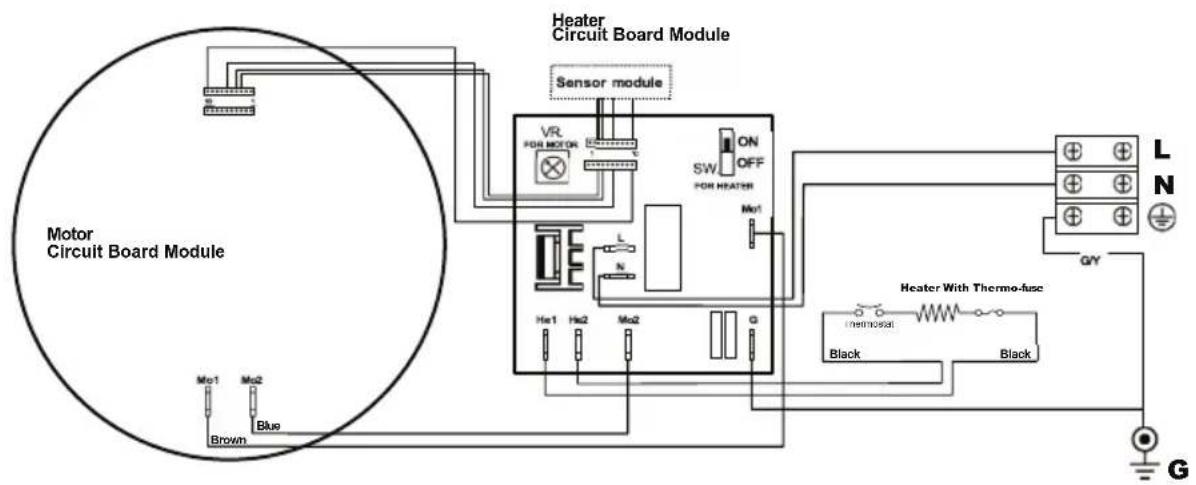
Circuit Diagram
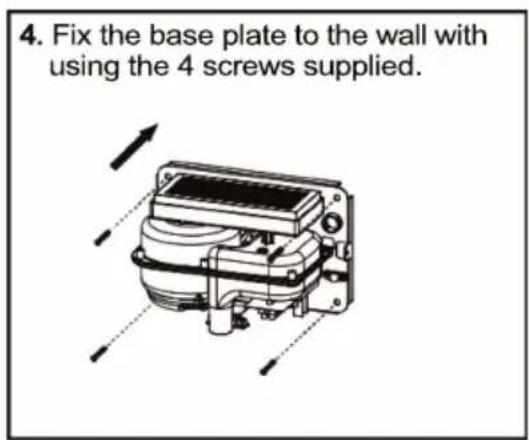
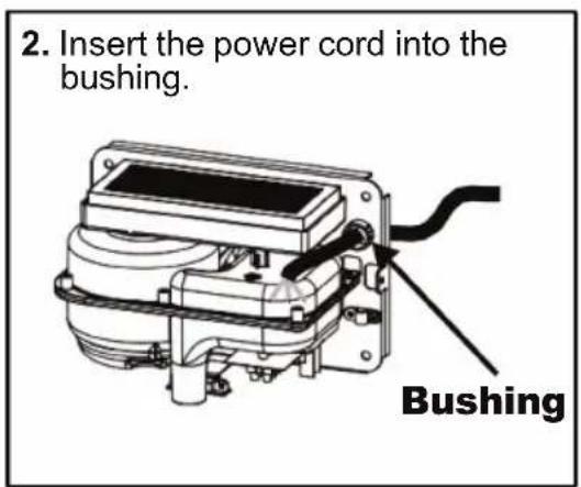
Installation
- Make sure the power supply breaker is switched off. Installation must be carried out in accordance with the current edition of the local wiring regulations code having jurisdiction. Installation should be performed only by a qualified electrician.
- Place template against wall at desired height (see mounting height recommendations) and mark locations of 4 mounting holes and wire service entry at knockout (KO) location.
Note: For two or more dryers, dryers should be no closer than 350 mm.
3. Connect the wire into terminal as below:
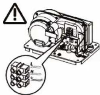
Connections:
A. Connect the live wire (colored black, brown or dark) to the terminal block marked "L".
B. Connect the neutral wire (colored white, blue or light) to the terminal block marked "N".
C. Connect the ground wire (colored green or green and yellow) to the terminal block marked "÷".
Note that colors of live and neutral wires depend on voltage of supply service.
Recommended Mounting Heights
- From bottom edge of dryer above finished floor (AFF)
| Men | 1270 mm |
| Women | 1194 mm |
| Children 4-7 years | 889 mm |
| Children 8-10 years | 991 mm |
| Children 11-13 years | 1092 mm |
| Children 14-16 years | 1194 mm |
| Handicapped | 1016 mm |
Cleaning and Maintenance
Periodic cleaning of the unit is recommended to ensure optimum performance.
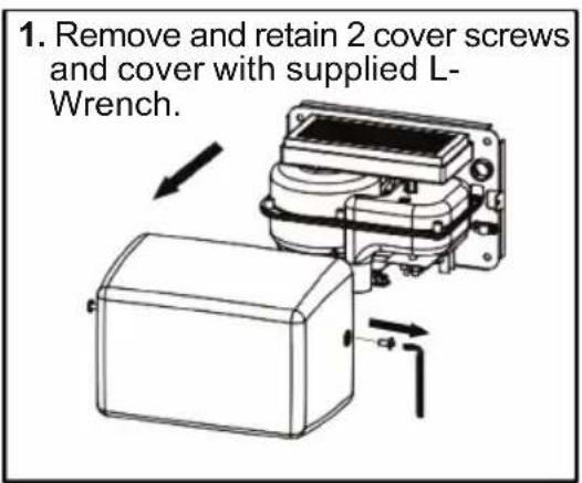
- Disconnect the electrical supply.
- Remove the two cover-mounting screws.
- Remove the cover.
- Clean all dust lint from the interior of the dryer.
- Do not flush with water.
- Wipe the cover with a damp cloth and mild cleaning solution. Do not Soak. Never use abrasives to clean the cover.
- Replace the cover. Do not overtighten the screws.
natural_image
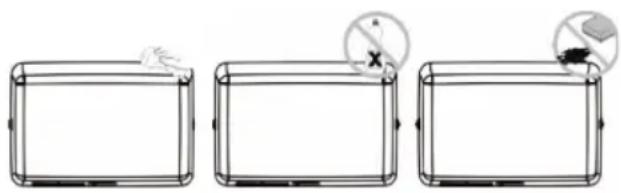
Three identical line drawings of a rectangular frame with a hand placed on top, and two circular icons showing a cross symbol (no text or labels)Operation
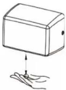
- No-touch operation.
- Shake excess water from hands.
- Place hands under the outlet to start operation.
- Rub hands lightly and rapidly.
- Stops automatically after hands are removed.
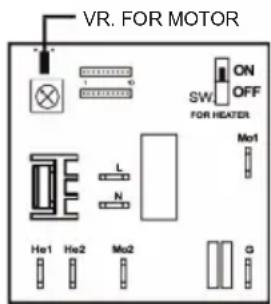
Warm Air Speed Adjustment
- Disconnect the device from the power supply, loosen the cover screws and remove the cover.
- Use a small Philips head screwdriver or plastic flat blade probe to turn VR shaft. Turn it gently clockwise
[CW] to increase power to maximum (+)
to reduce power as required (-)
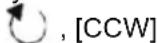
- DO NOT OVERTURN!
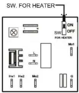
Heater Element Switch ON / OFF
- Disconnect the device from the power supply, loosen the cover screws and remove the cover.
- Adjust the heater switch on the PCB with a small plastic or wood flat blade probe.
2-1. Slide the switch to "ON": Heater ON.
2-2. Slide the switch to "OFF": Heater OFF.
Sensor range adjustment
To adjust the set sensor range, please contact customer service or the manufacturer.
natural_image
Simple line drawing of a rectangular box with an upward arrow and a small circular mark below, resting on a surface with fingers (no text or symbols)(+49 (0)7163/9988-100)
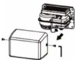
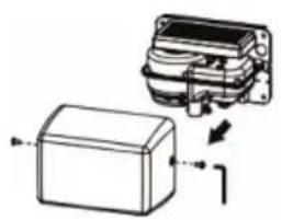
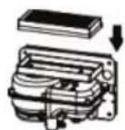
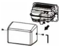
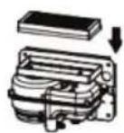
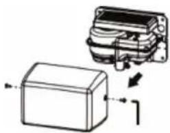
Change filter assembly
It is recommended to change the filter every six months.
natural_image
Diagram of a mechanical device with a box and housing, showing internal components and directional arrows (no text or symbols)
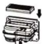

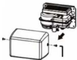
natural_image
Diagram of a rectangular electronic component with an arrow indicating direction, no text or symbols presentRemove and retain the 2 cover screws and the cover. Dispose of the old filter properly.
Replace the HEPA filter with a new one.
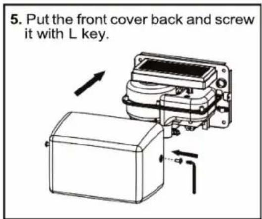
Put the cover back and screw it with L key.
Diagnostics and Remedies
| Symptom | Corrective Actions for Initial Installation Failures |
| If the dryer will not run | First ensure that the breaker supplying the dryer is operational. If it is, disconnect the power and remove the dryer cover. Taking suitable precautions to avoid shock hazard, reconnect the power and check for voltage at the terminal block. Verify that connections are made correctly. |
| The dryer cycles by itself or runs constantly | Ensure that there is no obstruction on or in front of the IR sensor. Clean any dirt or debris off the sensor lens. If problem persists, replace sensor. |
| The dryer makes a loud noise and does not run for a complete cycle | Ensure that the supply voltage is correct. Dryer will make a loud humming noise if the input voltage is too high. Verify voltage requirement on unit rating label and correct supply as required. If CBM has been damaged, replace CBM, IR sensor module and VR component and cable. |
| The dryer runs but air stream is low pressure and/or low velocity | Ensure that the supply voltage is correct. Dryer will run weakly if the input voltage is too low. Verify voltage requirement on unit rating label and correct supply as required. Check the filter and replace it if necessary. |
| Symptom | Corrective Actions for In-Service Failures |
| If the dryer will not run(Flashing purple light) | Turn off the power then activate the unit again. Wait at least 1 minute in between. If a warning display appears again, contact the service centre. |
| If the dryer will not run(Flashing yellow light) | |
| If the dryer will not run(Flashing pink light) | |
| The dryer runs but air stream is low pressure and/or low velocity(Flashing blue light) | |
| No hot air available | Check the heating element is on or off. If it is off, turn it on. If there is still no hot air, contact the service centre. |
Important Information
This Product falls within the scope of the Waste Electrical & Electronic Equipment Directive 2012/19/EU (WEEE)
NOTE:

This Product should not be disposed of with household waste. Please recycle where facilities exist.
Check with your local authority for recycling advice.
DONNÉES TECHNIQUES
CATÉGORIE DONNÉES DE PERFORMANCE
Connexions:
natural_image
Three identical wireframe rectangular frames with a hand holding a small object, each containing a circular icon with a cross and plus symbol (no text or labels)Opération
natural_image
Simple line drawing of a box with an arrow pointing to a small object, no text or symbols present.(+49 (0)7163/9988-100)
natural_image
Technical illustration of a mechanical component with an inset showing internal structure (no text or symbols)

natural_image
Diagram showing a device with a box and a mechanical component, no text or symbols present450 W, On: 450 W, off: 0 W
Conexiones:
natural_image
Three identical wireframe rectangular panels, each with a hand and a circular icon showing a cross symbol (no text or labels)Operación
natural_image
Simple line drawing of a rectangular box with an upward arrow and a small object below, no text or symbols present.(+49 (0)7163/9988-100)
natural_image
Technical line drawing of a mechanical component with an inset showing internal structure (no text or symbols)

natural_image
Technical line drawing of a mechanical component with an inset showing internal structure (no text or symbols)450 W, On: 450 W, off: 0 W
natural_image
Technical line drawing of a mechanical or electrical component with no visible text or symbolsnatural_image
Technical line drawing of a mechanical device with directional arrows indicating motion (no text or symbols)Verbindingen:
natural_image
Three identical wireframe rectangular panels, each with a hand icon and a circular symbol (no text or labels)Operatie
natural_image
Simple line drawing of a box with an upward arrow and a small mark below, no text or symbols present.(+49 (0)7163/9988-100)
Filter vervangen
natural_image
Diagram of a mechanical component with an inset showing internal structure and directional arrows (no text or symbols)

natural_image
Diagram of a mechanical component with an inset showing internal structure (no text or symbols)„DIRECTIVE OF THE EUROPEAN PARLIAMENT AND OF THE COUNCIL of 26 February 2014 on the harmonisation of the laws of the Member States relating to the making available on the market of electrical equipment designed for use within certain voltage limits“
EN 60335-1:2012; A11:2014 + A13:2017 + A1:2019 + A2:2019 + A14:2019 + A15:2021
EN 60335-2-23:2003; A2:2015 + A1:2008 + A11:2010
2014 / 30 / EU
"DIRECTIVE OF THE EUROPEAN PARLIAMENT AND OF THE COUNCIL on the harmonization of the laws of the Member States relating to electromagnetic compatibility"
EN IEC 55014-1:2021
EN IEC 55014-2:2021 Kat IV
EN IEC 61000-3-2:2019 + A1:2021
EN 61000-3-3 :2013 + A1:2019
IEC 61000-4-2 :2008; IEC 61000-4-3 :2020; IEC 61000-4-4 :2012
IEC 61000-4-5 :2017; IEC 61000-4-6 :2013; IEC 61000-4-11 :2020
ROHS 2011 / 65 / EU
EN 63000:2018


- Anschlüsse:
- Betrieb
- PERFORMANCE DATA
- General safety information
- WARNING
- DANGER
- Type Y attachment
- Circuit Diagram
- Installation
- Connect the wire into terminal as below:
- Connections:
- Recommended Mounting Heights
- Cleaning and Maintenance
- Operation
- Warm Air Speed Adjustment
- Heater Element Switch ON / OFF
- Sensor range adjustment
- Change filter assembly
- Diagnostics and Remedies
- Important Information
- DONNÉES TECHNIQUES
- CATÉGORIE DONNÉES DE PERFORMANCE
- Connexions:
- Opération
- Conexiones:
- Operación
- Operatie
- Filter vervangen
- / 30 / EU
- ROHS 2011 / 65 / EU
Brand : Starmix
Model : XT 1001 Mw
Category : Hand dryer