
T-C1 Mw - Hand dryer Starmix - Free user manual and instructions
Find the device manual for free T-C1 Mw Starmix in PDF.

| Product type | Automatic hand dryer |
| Brand | Starmix |
| Model | T-C1 Mw |
| Use | Commercial (hotels, spas, gyms, etc.) |
| Dimensions (W x D x H) | 280 x 182 x 293 mm |
| Weight | 4.0 kg |
| Power supply | 220-240 V ~ 50/60 Hz, 1550 W |
| Protection class | I |
| Protection rating | IP23 |
| Air flow rate | 38 l/s |
| Air speed | 87 m/s |
| Noise level | 76 dB(A) |
| Relative drying time | 17 seconds |
| Sensor type | Contactless infrared sensor |
| Safety shut-off | Automatic after 35 seconds (hand dryer) |
| Thermal safety | Temperature limiter and thermal fuse |
| Mounting | Wall-mounted, with drilling template and mounting plate |
| Maintenance | Clean the intake grille every 6 months |
| Repairability | By a qualified professional |
| Power cable | H05VV-F3G1, with protective conductor |
| Delivery content | Appliance, mounting plate, screws, wall plugs, drilling template, an angled screwdriver, user manual |
Frequently Asked Questions - T-C1 Mw Starmix
User questions about T-C1 Mw Starmix
0 question about this device. Answer the ones you know or ask your own.
Ask a new question about this device
Download the instructions for your Hand dryer in PDF format for free! Find your manual T-C1 Mw - Starmix and take your electronic device back in hand. On this page are published all the documents necessary for the use of your device. T-C1 Mw by Starmix.
USER MANUAL T-C1 Mw Starmix
Operating instructions
natural_image
Line drawing of a 3D geometric object with curved surfaces and no visible text or symbolsDE Bedienungsanleitung (original) 9
GB Operating Instructions (original).... 17
natural_image
Technical line drawing of a 3D geometric object with internal cutouts and labeled point '1' (no text or symbols beyond label)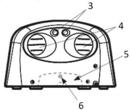
natural_image
Technical line drawing of a car front panel with no text or symbols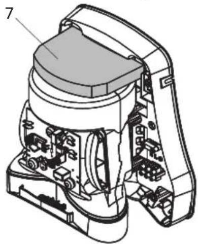
natural_image
Technical line drawing of a mechanical device with internal components and labeled part (7), no readable text or symbols present.E
natural_image
Illustration of a handheld electric shaver with a pointed tip and two small spheres at the base (no text or symbols)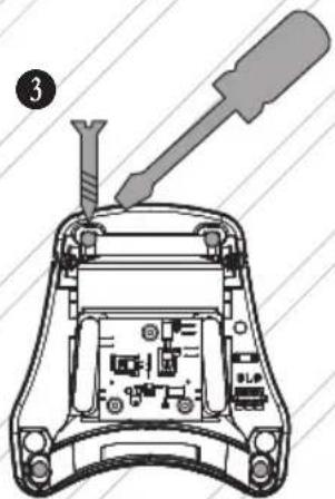
F
natural_image
Diagram showing a vehicle approaching a wall-mounted cable with an arrow indicating direction (no text or symbols)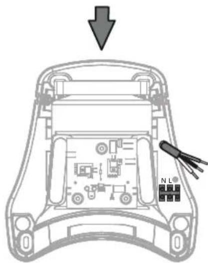
G
H
I
1 Important safety information
Carefully read the operating instructions all the way through before operating the equipment and retain them for future reference.
The pictures in these instructions refer to all available versions of the model and may be different from the actual scope of delivery.
Explanation of symbols and signs used

This is the warning symbol. It warns against possible risk of injury. Follow all instructions which are marked with this sign to avoid injury or death. The warning symbol always appears in association with the signal words DANGER, WARNING and CAUTION.
Symbol Signal word Description

DANGER Identifies a hazard with a high degree of risk which will cause death or serious injury if not avoided.

WARNING Identifies a hazard with a medium degree of risk which could cause death or serious injury if not avoided.

CAUTION Identifies a hazard with a low degree of risk which could cause minor or moderate injury if not avoided.
NOTICE Identifies a hazard which could result in material damage if not avoided.

Identifies a requirement which needs to be met before an action is taken.
1./2./3. Identifies steps to be taken one after the other by the user.

Identifies the results of an action.
Qualification of operating, installation and maintenance personnel
The installation and electrical connection may only be executed by trained qualified personnel.
Maintenance may only be performed by persons who have been trained to handle the device and explicitly assigned to this task.
This device may be used by children aged 8 and over as well as by persons with reduced physical, sensory or mental capacities or a lack of experience and knowledge if they are supervised or have been instructed on safe use of the device and understand the associated risks. Children must be supervised to ensure that they do not play with the device.
en
Intended use
The device is used to rapidly dry hands (Type T-C1 M / T-C1 Mw) and hair (Type TH-C1 M / TH-C1 Mw).
The device is intended for commercial use, for example for use in hotels, public baths, fitness studios, spas, saunas, public facilities, industries and businesses.
The manufacturer does not accept liability for damages caused by misappropriation, inappropriate usage or incorrect repairs.
Avoid danger from electric shocks
The voltage on the rating plate must match the mains voltage. Only connect the vacuum cleaner to a sufficiently protected electric socket.
Do not pull the mains connection cable over sharp edges, do not bend it or clamp it. Only replace a damaged mains connection cable with one meeting the specifications in the Technical Data chapter.
Do not operate the device including the accessories in the following cases:
– Power cord is defective or has cracks
– Device is noticeably damaged, e.g. by cracks in the housing
– If an invisible defect is suspected, e.g. after a fall or impact
In the following cases, unplug the power cord, switch off the circuit breaker or unscrew the fuse:
– When the device makes unusual noises
– Before any maintenance or cleaning
When unplugging, only pull on the mains plug and not on the mains connection cable. Never touch the mains plug with wet hands.
Avoiding risks during installation
For the installation and operation of the device, please observe:
– The national and regional regulations
– The technical regulations and guidelines
– The provisions of the local authorities
Avoiding risks during operation
Do not use the device in rooms with toxic, explosive or flammable fumes and gases, or with microbiologically contaminated air. Do not insert any objects into the opening of the device. Do not cover the device or deposit objects on it.
Avoid any danger during maintenance and repair
Only have repairs carried out by experts. Only use original accessories and spare parts.
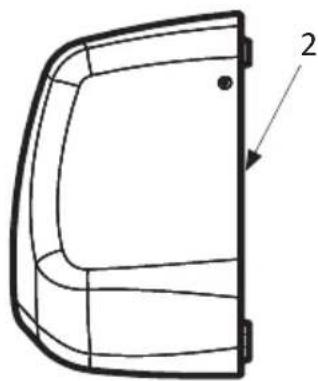
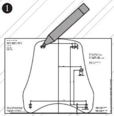
2 Device structure
See Fig. A
1 Device 5 Air intake grille
2 Mounting plate 6 Locking screw
3 Sensor 7 Motor protection filter
4 Outlet opening
3 Installation
Unpacking
- Take all parts out of the packaging.
Scope of delivery:
1 Device 1 Offset screwdriver TX25
4 Screws 1 Drilling template
4 Dowels 1 Instruction manual
Installing the device
See Fig. B, C, D, E

CAUTION
Unsuitable installation material and tooling!
Risk of injury caused by the device falling down.
Before installation:
- Check if screws and dowels supplied with the device are suitable for the surface material.
- Have suitable tools to hand for installation.
Preparation (see Fig. B, C):
- Select a wall with a sturdy, weight-bearing surface.
- Observe installation height and minimum distances.
- Have suitable fastening material to hand for installation on the wall.
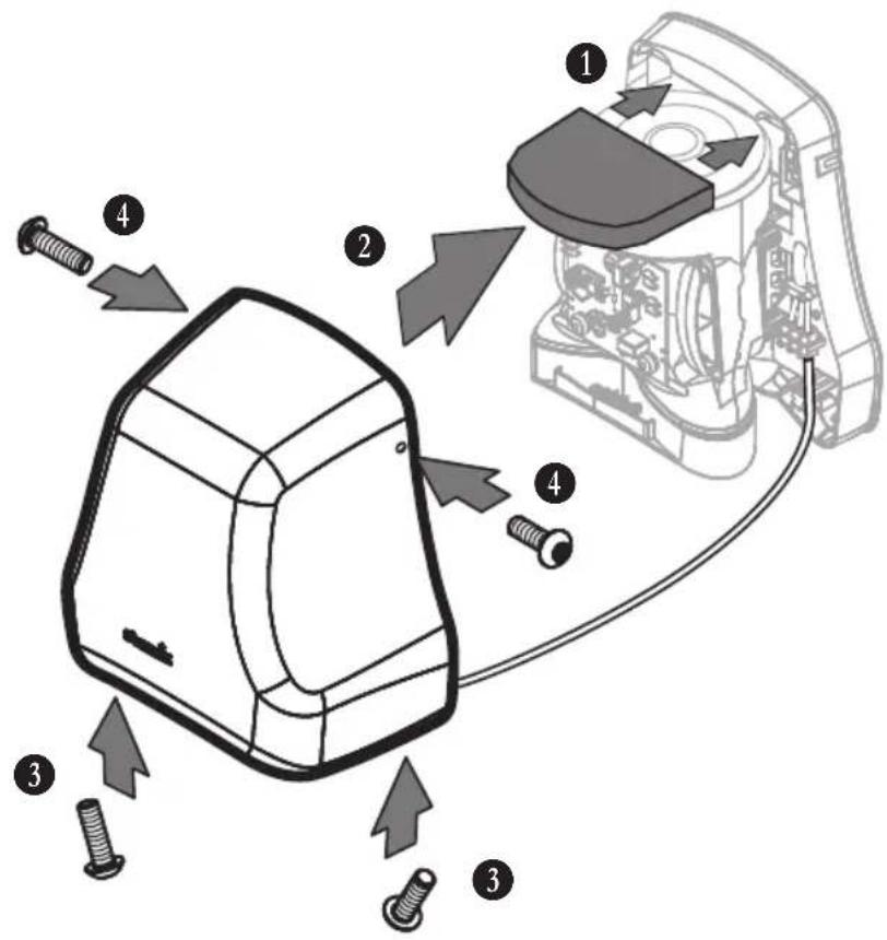
Remove hood from the device (see Fig. D):
- Loosen upper two fastening screws of the hood.
- Loosen lower two fastening screws of the hood.
- Remove hood from the mounting plate.
- Disconnect protective earth wire (PE) of the hood from the terminal. NOTICE! Do not open the screw on the metal hood.
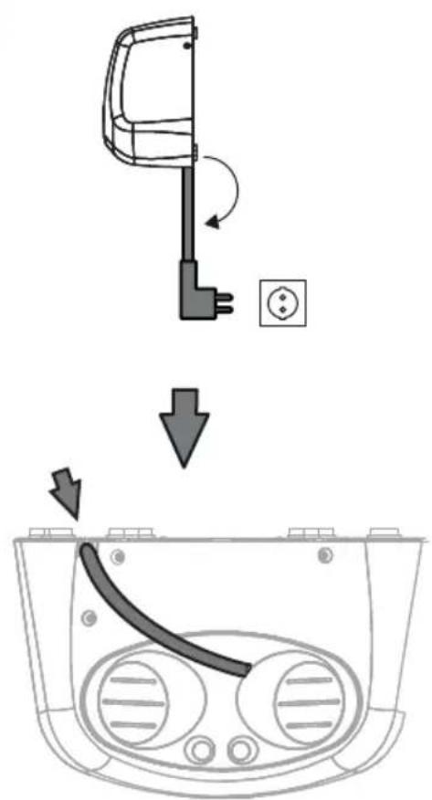
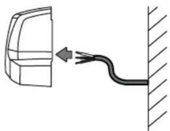
Fasten mounting plate to the wall (see Fig. E, F):
- Hold drilling template or mounting plate against the wall and mark the drill holes.
- Drill the holes.
- Insert electrical connection cable into cable duct of the mounting plate (see Fig. F) and fasten the mounting plate to the wall.
Connect device to power supply
See Fig. G, H
Observe the following conditions for the electrical connection:
- Only connect the device to a properly installed grounded socket.
- With fixed connection: Supply line must have a switch-off device, e.g. a circuit breaker that can be switched off or a screw-in fuse.
- Connect the device to an electrical supply line with a residual current circuit breaker.
- Do not connect other loads to the electrical supply line of the device.

DANGER
Live electrical supply line and device components!
Risk of deadly electric shock in case of contact.
Before performing any work on the device:
-
Unplug power cord. With fixed connection: Switch off circuit breaker or unscrew fuse.
-
Secure against accidental switching on.
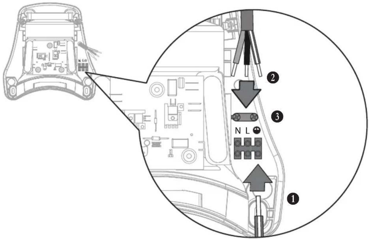
Connect electrical cables (see Fig. G):
- Screw protective earth wire of the hood to terminal on the mounting plate.
- Connect electrical supply cable to terminal.
- Insert electrical supply cable into strain relief and fix it.
Place hood on device (see Fig. H):
- Place hood on device. NOTICE! Do not damage protective earth wire. Ensure that motor protection filter (Fig. A, item 7) is correctly seated.
- Tighten lower two fastening screws of the hood.
- Tighten upper two fastening screws of the hood.
- Plug the plug into socket, switch on automatic circuit breaker or screw in fuse.
4 Initial operation
Please observe the following before initial operation
Ensure that the following requirements are met:
△ Safety distances according to DIN have been observed.
△ The power supply is properly connected.
△ All filters are inserted and undamaged.
Switching on and off
The device is switched on and off without contact by means of the sensor:
- Hold hands or head under the outlet opening of the device.
→ Sensor automatically switches on the device.
→ Device is switched off as soon as hands or head are removed from sensor range.
→ Device is automatically switched off if hands or head remain in sensor range for a longer period of time:
Hand dryer: 35 seconds
Hair dryer: 4 minutes
Safety features
The hand dryer is equipped with the following safety features:
– Safety cut-off sensor after 35 seconds
– Safety temperature limiter in case of overheating, e.g. if outlet opening is blocked
– Thermal fuse in case of overheating
The hair dryer is equipped with the following safety features:
– Safety cut-off sensor after approx. 4 minutes, e.g. in case of chewing gum vandalism
– Safety temperature limiter in case of overheating, e.g. if outlet opening is blocked
– Thermal fuse in case of overheating
5 Conduct in case of emergency
In cases of fire hazard, electrical shock, mechanical damage, unusual operating conditions or misuse, proceed as follows:
- Unplug power cord. With fixed connection: Switch off circuit breaker or unscrew fuse.
- Secure against accidental switching on.
6 Troubleshooting and repairs
Malfunction Cause Remedy
| The device does not start Sensor is soiled Remove dirt from sensor and wipe |
with damp cloth
Fuse has tripped Switch on circuit breaker or
replace fuse
Overheating due to blocked outlet
Clean out outlet opening, allow
opening
The thermal fuse was triggered Have
device to cool down
customer service
Air output is insufficient Air intake grille is soiled Clean air intake grille
Do not take any further action; contact customer service instead.
7 Maintenance
Clean the air intake grille
See Fig. I
Clean the air intake grille at regular intervals, but at least every 6 months. The air intake grille may only be cleaned by trained specialist personnel.

DANGER
Live electrical supply line and device components!
Risk of deadly electric shock in case of contact.
Before performing any work on the device:
- Unplug power cord. With fixed connection: Switch off circuit breaker or unscrew fuse.
- Secure against accidental switching on.
Remove hood from the device:
- Unplug power cord. With fixed connection: Switch off circuit breaker or unscrew fuse.
- Loosen upper two fastening screws of the hood.
- Loosen lower two fastening screws of the hood.
- Remove hood from the mounting plate.
- Disconnect protective earth wire (PE) of the hood from terminal. NOTICE! Do not open the screw on the metal hood.
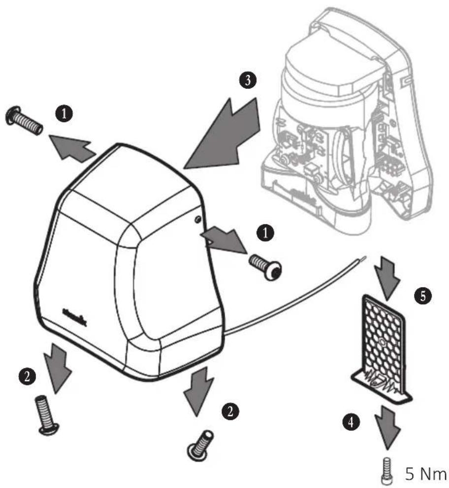
Clean the air intake grille:
- Unscrew locking screw on air intake grille on the underside of the device.
- Pull air intake grille downwards out of the device.
- Remove any lint and adhering dirt from the air intake grille.
- Push air intake grille into the device from below.
- Fix air intake grille with the locking screw.
Place hood on the device:
- Place hood on the device. NOTICE! Do not damage protective earth wire. Ensure that motor protection filter (Fig. A, item 7) is correctly seated.
- Tighten lower two fastening screws of the hood.
- Tighten upper two fastening screws of the hood.
- Plug the plug into socket, switch on automatic circuit breaker or screw in fuse.
Cleaning the device
Do not clean the device with a high-pressure cleaner. Only use a damp cloth and mild cleaning agents to clean the device. Acids, acetone or solvents can damage the housing or device components.
8 Disposal
Old equipment contains valuable materials which are designed for re-processing. The vacuum cleaners must not be thrown away in the normal household waste, but should be disposed of at a suitable proper collection system, e.g. via your communal disposal location.
9 Technical data
| T-C1 (M / Mw) TH-C1 (M / Mw) | |||
| Voltage V 220-240 | 220-240 | ||
| Frequency Hz 50/60 | 50/60 | ||
| Power consumption (max.) W 1550 | 900 | ||
| Fuse A 16 | 16 | ||
| Heat output W 550 | 400 | ||
| Motor output W 1000 | 500 | ||
| Air volume l/s 38 | 22 | ||
| Air speed m/s | 87 | 50 | |
| Sound level dB(A) | 76 | 76 | |
| Protection class | I | I | |
| Protection type IP | 23 | 23 | |
| Relative drying time s | 17 | ||
| Width mm | 280 | 280 | |
| Depth mm | 182 | 182 | |
| Height mm | 293 | 293 | |
| Weight kg 4,0 | 4,0 | ||
Mains connection cable: H05VV-F3G1
10 Declaration of conformity
| Declaration of conformity | |
| We hereby declare that the machine described below complies with the relevant basic safety and health requirements of the EC Directives, both in its basic design and construction as well as in the version put into circulation by us. This declaration shall cease to be valid if the machine is modified without our prior approval. | |
| Product: Hot air hand dryers and hair dryers | |
| Type: AirStar | |
| The design of the appliance corresponds to the following pertinent regulations: | EMC Directive 2014/30/EUEC Directive 2014/35/EURoHS 2011/65/EU |
| Applied harmonized standards: EN 60335-1:2012 | |
| Applied national standards and technical specifications: | DIN EN 55014-1 (VDE 0875-14-1):2018-08 EN 55014-1:2017DIN EN 55014-2 (VDE 0875-14-2):2016-01 EN 55014-2:2015DIN EN 60335-1 (VDE 0700-1):2012-10DIN EN 60335-1 Ber.1 (VDE 0700-1 Ber.1):2014-04DIN EN 60335-1/A13 (VDE 0700-1/A13):2018-07EN 60335-1:2012/A13:2017DIN EN 61000-3-2 (VDE 0838-2):2015-03DIN EN 61000-3-3 (VDE 0838-3):2014-03DIN EN 60335-2-23 (VDE 0700-23):2015-06DIN EN 62233 (VDE 0700-366):2008-11DIN EN 62233 Ber.1 (VDE 0700-366 Ber.1):2009-04 |
| Authorized documentation representative: ELECTROSTAR GmbH, Hans-Zinser-Str. 1-3, 73061 Ebersbach/Fils, Germany | |
| 25.07.2020 | Carsten GresserHead of Quality Assurance |
Symbole Mention Description

Forberedelse (se fig. B, C):
Unngå farer under driften
Forberedelse (se fig. B, C):
Příprava (viz obr. B, C):
Vidi sl. B, C, D, E.

OPREZ
Neprikladan materijal za montažu i alat!
Opasnost od ozljeda uslijed uređaja u padu.
Prije montaže:
- Provjerite jesu li vijci i usadnice isporučeni s uređajem prikladni za podlogu.
- Pripremite prikladan alat za montažu.
Priprema (vidi sl. B, C):
- Odaberite zid sa stabilnom, nosivom podlogom.
- Obratite pažnju na visinu montaže i minimalne razmake.
- Pripremite prikladan pričvrsni materijal za montažu na zid.
Vidi sl. B, C, D, E.

OPREZ
Neodgovarajući materijal za montažu i alat!
Priprema (vidi sl. B, C):
- Izaberite zid sa stabilnom podlogom koja ima dovoljnu nosivost.
- Pridržavajte se visine za montažu i minimalnog rastojanja.
- Obezbedite odgovarajući materijal za montažu na zid.
Skidanje haube sa uređaja (vidi sl. D):
- Odvijte oba gornja pričvrsna zavrtnja haube.
- Odvijte oba donja pričvrsna zavrtnja haube.
- Skinite haubu sa ploče za montažu.
- Žicu uzemljenja (PE) haube otkačite sa priključne stezaljke. PAŽNJA! Nemojte da odvijate zavrtnje na metalnom kućištu.
Pričvršćivanje ploče montažu na zid (vidi sl. E, F):
- Šablon za bušenje ili ploču za montažu zadržite za zid i obeležite otvore za bušenje za montažu.
- Napravite otvore.
- Električne vodove postavite u vodicu kablove ploče za montažu (vidi sl. F) i pričvrstite ploču za montažu na zid.
Carsten Gresser Head of Quality Assurance
Carsten Gresser Head of Quality Assurance
1 重要安全注意事项


- Important safety information
- Explanation of symbols and signs used
- Qualification of operating, installation and maintenance personnel
- Intended use
- Avoid danger from electric shocks
- Avoiding risks during installation
- Avoiding risks during operation
- Avoid any danger during maintenance and repair
- Device structure
- Installation
- Unpacking
- Installing the device
- CAUTION
- Connect device to power supply
- DANGER
- Initial operation
- Please observe the following before initial operation
- Switching on and off
- Safety features
- Conduct in case of emergency
- Troubleshooting and repairs
- Maintenance
- Clean the air intake grille
- Remove hood from the device:
- Clean the air intake grille:
- Place hood on the device:
- Cleaning the device
- Disposal
- Declaration of conformity
- Unngå farer under driften
- Forberedelse (se fig. B, C):
- OPREZ
- 重要安全注意事项
Brand : Starmix
Model : T-C1 Mw
Category : Hand dryer