GOF 1250 CE Professional - Milling machine BOSCH - Free user manual and instructions
Find the device manual for free GOF 1250 CE Professional BOSCH in PDF.
Frequently Asked Questions - GOF 1250 CE Professional BOSCH
User questions about GOF 1250 CE Professional BOSCH
0 question about this device. Answer the ones you know or ask your own.
Ask a new question about this device
Download the instructions for your Milling machine in PDF format for free! Find your manual GOF 1250 CE Professional - BOSCH and take your electronic device back in hand. On this page are published all the documents necessary for the use of your device. GOF 1250 CE Professional by BOSCH.
USER MANUAL GOF 1250 CE Professional BOSCH
YkpaHcbKa ..CtoPiHa 145
Kaak. 5et 153
Româna...... Pagnia 162
General Power Tool SafetyWarnings
WARNING
Read all safety warnings, instructions, illustrations and specifica
tions provided with this power tool. Failure to follow all instructions listed below may result in electric shock, fire and/ or serious injury.
Save all warnings and instructions for future reference.
The term "power tool" in the warnings refers to your mains-operated (corded) power tool or battery-operated (cordless) power tool.
Work area safety
- Keep work area clean and well lit. Cluttered or dark areas invite accidents.
Do not operate power tools in explosive atmospheres, such as in the presence of flammable liquids, gases or
dust. Power tools create sparks which may ignite the dust or fumes.
- Keep children and bystanders away while operating a power tool. Distractions can cause you to lose control.
Electrical safety
Power tool plugs must match the outlet. Never modify the plug in any way. Do not use any adapter plugs with earthed (grounded) power tools. Unmodified plugs and matching outlets will reduce risk of electric shock.
- Avoid body contact with earthed or grounded surfaces, such as pipes, radiators, ranges and refrigerators. There is an increased risk of electric shock if your body is earthed or grounded.
Do not expose power tools to rain or wet conditions. Water entering a power tool will increase the risk of electric shock.
Do not abuse the cord. Never use the cord for carrying, pulling or unplugging the power tool. Keep cord away from heat, oil, sharp edges or moving parts. Damaged or entangled cords increase the risk of electric shock.
When operating a power tool outdoors, use an extension cord suitable for outdoor use. Use of a cord suitable for outdoor use reduces the risk of electric shock.
If operating a power tool in a damp location is unavoidable, use a residual current device (RCD) protected supply. Use of an RCD reduces the risk of electric shock.
Personal safety
Stay alert, watch what you are doing and use common sense when operating a power tool. Do not use a power tool while you are tired or under the influence of drugs, alcohol or medication. A moment of inattention while operating power tools may result in serious personal injury.
Use personal protective equipment. Always wear eye protection. Protective equipment such as a dust mask, non-skid safety shoes, hard hat or hearing protection used for appropriate conditions will reduce personal injuries.
Prevent unintentional starting. Ensure the switch is in the off-position before connecting to power source and/or battery pack, picking up or carrying the tool. Carrying power tools with your finger on the switch or energising power tools that have the switch on invites accidents.
Remove any adjusting key or wrench before turning the power tool on. A wrench or a key left attached to a rotating part of the power tool may result in personal injury.
Do not overreach. Keep proper footing and balance at all times. This enables better control of the power tool in unexpected situations.
Dress properly. Do not wear loose clothing or jewellery. Keep your hair and clothing away from moving
parts. Loose clothes, jewellery or long hair can be caught in moving parts.
If devices are provided for the connection of dust extraction and collection facilities, ensure these are connected and properly used. Use of dust collection can reduce dust-related hazards.
Do not let familiarity gained from frequent use of tools allow you to become complacent and ignore tool safety principles. A careless action can cause severe injury within a fraction of a second.
Power tool use and care
Do not force the power tool. Use the correct power tool for your application. The correct power tool will do the job better and safer at the rate for which it was designed.
Do not use the power tool if the switch does not turn it on and off. Any power tool that cannot be controlled with the switch is dangerous and must be repaired.
- Disconnect the plug from the power source and/or remove the battery pack, if detachable, from the power tool before making any adjustments, changing accessories, or storing power tools. Such preventive safety measures reduce the risk of starting the power tool accidentally.
- Store idle power tools out of the reach of children and do not allow persons unfamiliar with the power tool or these instructions to operate the power tool. Power tools are dangerous in the hands of untrained users.
- Maintain power tools and accessories. Check for misalignment or binding of moving parts, breakage of parts and any other condition that may affect the power tool's operation. If damaged, have the power tool repaired before use. Many accidents are caused by poorly maintained power tools.
- Keep cutting tools sharp and clean. Properly maintained cutting tools with sharp cutting edges are less likely to bind and are easier to control.
Use the power tool, accessories and tool bits etc. in accordance with these instructions, taking into account the working conditions and the work to be performed. Use of the power tool for operations different from those intended could result in a hazardous situation.
- Keep handles and grasping surfaces dry, clean and free from oil and grease. Slippery handles and grasping surfaces do not allow for safe handling and control of the tool in unexpected situations.
Service
Have your power tool serviced by a qualified repair person using only identical replacement parts. This will ensure that the safety of the power tool is maintained.
Safety information for routers
Hold the power tool by insulated gripping surfaces only, because the cutter may contact its own cord. Cutting a "live" wire may make exposed metal parts of the
16|English
power tool "live" and could give the operator an electric shock.
Use clamps or another practical way to secure and support the workpiece to a stable platform. Holding the work by your hand or against the body leaves it unstable and may lead to loss of control.
The permitted speed of the cutting bit must be at least equal to the maximum speed marked on the power tool. If cutting bits run faster than their rated speed, they may break and fly off.
- Routers and other accessories must be able to fit exactly in the tool holder (collet) of your power tool. Application tools that do not fit exactly in the tool holder of the power tool will turn unevenly, vibrate heavily and may cause a loss of control.
Only bring the power tool into contact with the workpiece when switched on. Otherwise there is danger of kickback if the cutting tool jams in the workpiece.
- Do not put your hands in the routing area or close to the router. Grip the auxiliary handle with your other hand. Holding the router with both hands avoids injury.
- Never rout over metal objects, nails or screws. The router could become damaged and cause increased vibration.
- Use suitable detectors to determine if utility lines are hidden in the work area or call the local utility company for assistance. Contact with electric lines can lead to fire and electric shock. Damaging a gas line can lead to explosion. Penetrating a water line causes property damage or may cause an electric shock.
- Do not use blunt or damaged routers. Blunt or damaged routers cause increased friction, create imbalances and may become jammed.
Always wait until the power tool has come to a complete stop before placing it down. The application tool can jam and cause you to lose control of the power tool.
Hold the power tool firmly with both hands and make sure you have a stable footing. The power tool can be more securely guided with both hands.
Products sold in GB only:
Your product is fitted with an BS 1363/A approved electric plug with internal fuse (ASTA approved to BS 1362).
If the plug is not suitable for your socket outlets, it should be cut off and an appropriate plug fitted in its place by an authorised customer service agent. The replacement plug should have the same fuse rating as the original plug.
The severed plug must be disposed of to avoid a possible shock hazard and should never be inserted into a mains socket elsewhere.
- Never swallow button cells. Swallowing button cells can result in severe internal burns and death within two hours.

Ensure that the button cell is kept out of the reach of children. If you suspect that someone has swallowed a button cell or that a button cell has entered the body in another way, seek medical attention immediately.

Ensure that battery replacement is carried out properly. There is a risk of explosion.
Do not attempt to recharge the button cell and do not short circuit the button cell. The button cell may leak, explode, catch fire and cause personal injury.
- Remove and dispose of drained button cells correctly. Drained button cells may leak and damage the product or cause personal injury.
- Do not overheat the button cell or throw it into fire. The button cell may leak, explode, catch fire and cause personal injury.
Do not damage the button cell and or take the button cell apart. The button cell may leak, explode, catch fire and cause personal injury.
- Do not allow damaged button cells to come into contact with water. Leaking lithium may mix with water to create hydrogen, which could cause a fire, an explosion, or personal injury.
Product Description and Specifications

Read all the safety and general instructions. Failure to observe the safety and general instructions may result in electric shock, fire and/or serious injury.
Please observe the illustrations at the beginning of this operating manual.
Intended use
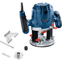
The power tool is intended for copy routing as well as routing grooves, edges, profiles and elongated holes in wood, plastic and light building materials while resting firmly on the workpiece.
Can even be used to machine non-ferrous metals when used at a low speed with the appropriate router bits.
Product features
The numbering of the product features refers to the diagram of the power tool on the graphics page.
(1) Right handle (insulated gripping surface)
(2) Lock-on button for on/off switch
(3) Light ring (GOF 1250 LCE)
(4) Cap nut with collet
(5) Router bit ^A)
(6) Spindle locking lever
English | 17
(7) Screw for parallel guide rods (2x)
(8) Chip protection
(9) Step buffer
(10) Adjusting screws for step buffer
(11) Guide plate
(12) Holder for parallel guide rods
(13) Base plate
(14) Depth stop
(15) Screw for depth stop fixing
(16) Button for zero point of depth stop (GOF 1250 LCE)
(17) Button for switching the unit of measure (mm/inch) (GOF 1250 LCE)
(18) On/off switch for digital depth display (GOF 1250 LCE)
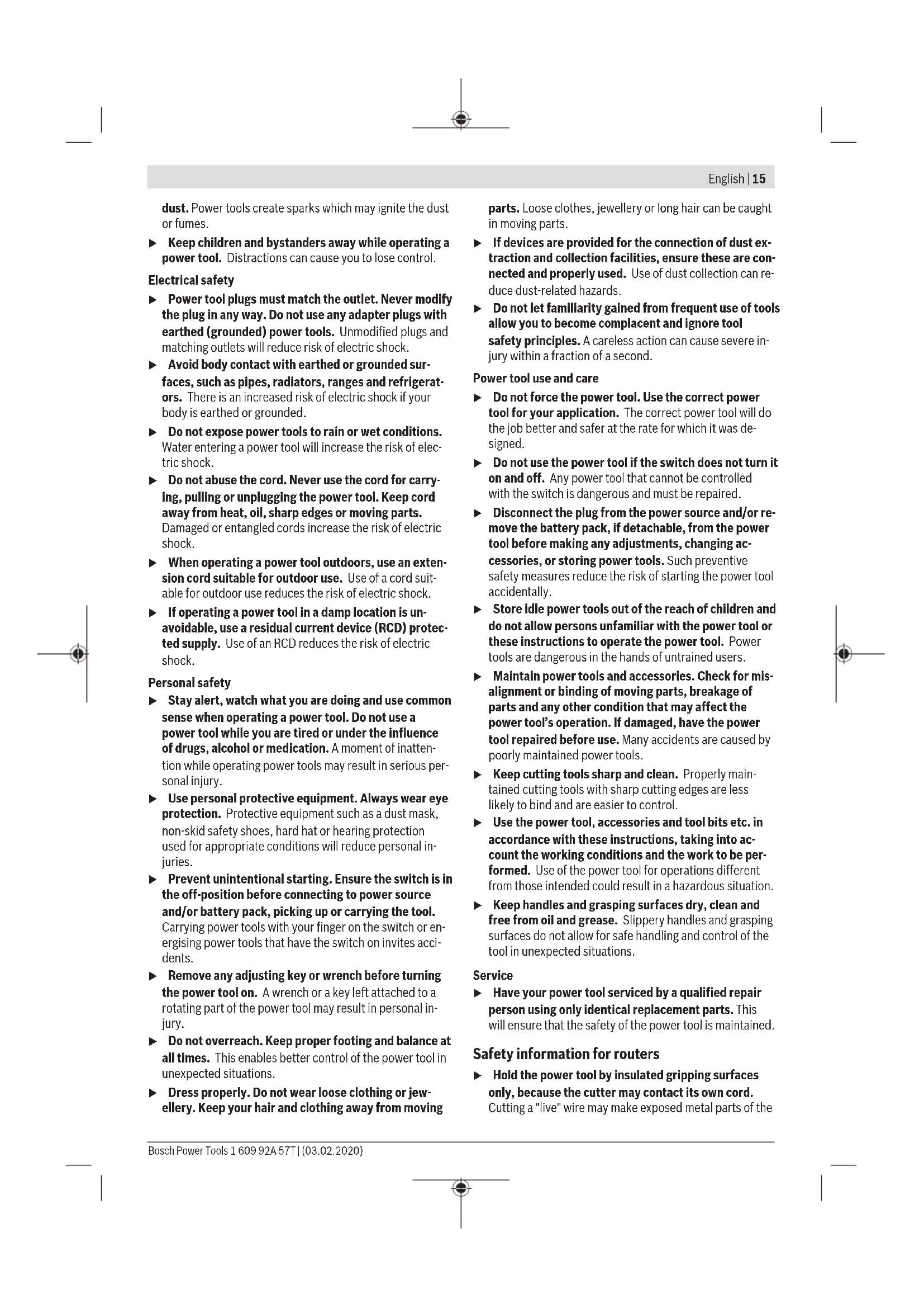
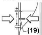
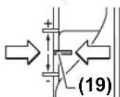
(19) Adjustment range for fine adjustment of routing depth
(20) Left handle (insulated gripping surface)
(21) Display (GOF 1250 LCE)
(22) Battery compartment cover (GOF 1250 LCE)
(23) Release lever
(24) Scale for fine adjustment of routing depth
(25) Adjustment knob for fine adjustment of routing depth
(26) Scale for depth-of-cut fine adjustment (GOF 1250 LCE)
(27) Slide with index mark (GOF 1250 LCE)
(28) Speed preselection thumbwheel
(29) On/off switch
(30) Extraction hose port
(31) Open-ended spanner with width across flats of 19 mm
(32) Extraction hose (dia. 35 mm) ^A)
(33) Parallel guide
(34) Rod for parallel guide (2x)
(35) Wing bolt for parallel guide fine adjustment (2x)
(36) Wing bolt for parallel guide coarse adjustment (2x)
(37) Adjustment knob for parallel guide fine adjustment
(38) Adjustable fence for parallel guide
(39) Extraction adapter for parallel guide
(40) SDS guide-bushing adapter
(41) Fastening screw for guide bushing adapter (2x)
(42) Release lever for guide bushing adapter
(43) Guide bushing
(44) Pan head screw for guide plate fixing (5x)
(45) Centring pin
(46) Seal
A) Accessories shown or described are not included with the product as standard. You can find the complete selection of accessories in our accessories range.
Technical data
| Router GOF 1250 CE GOF 1250 LCE | |||
| Article number | 3601 F26 0.. 3601 F26 1.. | ||
| Rated power input W 1250 1250 | |||
| No-load speed min | -1 | 10000-24000 | 10000-24000 |
| Speed preselection ● ● | |||
| Constant electronic control ● ● | |||
| Soft start ● ● | |||
| Connection for dust extraction ● ● | |||
| Digital depth display - ● | |||
| Light ring - ● | |||
| Compatible collets mm | inches | 6-8 | 6-8 |
| ¼ | ¼ | ||
| Router cage stroke mm 60 | 60 | ||
| Weight according to EPTA-Procedure 01:2014 | kg | 3.6 | 3.7 |
| Protection class | ☐/II | ☐/II | |
The specifications apply to a rated voltage [U] of 230 V. These specifications may vary at different voltages and in country-specific models.
Noise/Vibration Information
Noise emission values determined according to EN 62841-2-17.
Typically the A-weighted noise level of the power tool are: 93 dB(A); sound power level 104 dB(A). Uncertainty K = 3 dB.
Wear hearing protection!
Vibration total values a_h (triax vector sum) and uncertainty K determined according to EN 62841-2-17: a_n = 7 m/s^2 , K = 1.5 m/s^2 .
The vibration level and noise emission value given in these instructions have been measured in accordance with a
18|English
standardised measuring procedure and may be used to compare power tools. They may also be used for a preliminary estimation of vibration and noise emissions.
The stated vibration level and noise emission value represent the main applications of the power tool. However, if the power tool is used for other applications, with different application tools or is poorly maintained, the vibration level and noise emission value may differ. This may significantly increase the vibration and noise emissions over the total working period.
To estimate vibration and noise emissions accurately, the times when the tool is switched off or when it is running but not actually being used should also be taken into account. This may significantly reduce vibration and noise emissions over the total working period.
Implement additional safety measures to protect the operator from the effects of vibration, such as servicing the power tool and application tools, keeping their hands warm, and organising workflows correctly.
Fitting
Pull the plug out of the socket before carrying out any work on the power tool.
Inserting the Router Bit (see figure A)
Wearing protective gloves while fitting and changing router bits is recommended.
Router bits are available in a wide variety of designs and qualities depending on the intended application.
Router bits made of high-performance high-speed steel (HSS) are suited to machining soft materials such as soft-wood and plastic.
Router bits with carbide tips are especially suitable for hard and abrasive materials such as hardwood and aluminium.
Original router bits from the extensive range of Bosch accessories are available from your specialist dealer.
Only use undamaged and clean router bits.
- Swivel the spindle locking lever (6) anticlockwise as far as it will go (0). If necessary, turn the motor spindle by hand until you hear it engage.
- Loosen the cap nut (4) with the open-ended spanner (31) (width across flats 1.9mm ) by turning it clockwise (2).
- Slide the router bit into the collet. The bit shank must be inserted into the collet at least up to the mark.
- Tighten the cap nut (4) with the open-ended spanner (31) (width across flats 19mm ) by turning it anticlockwise. Lock the spindle locking lever (6) fully back into place.
Do not insert a router bit with a diameter larger than 50mm when the guide bushing is not mounted. These router bits will not fit through the base plate.
Do not, under any circumstances, tighten the collet with the tightening nut until a router bit has been fitted. The collet may otherwise become damaged.
Dust/Chip Extraction
The dust from materials such as lead paint, some types of wood, minerals and metal can be harmful to human health. Touching or breathing in this dust can trigger allergic reactions and/or cause respiratory illnesses in the user or in people in the near vicinity.
Certain dusts, such as oak or beech dust, are classified as carcinogenic, especially in conjunction with wood treatment additives (chromate, wood preservative). Materials containing asbestos may only be machined by specialists.
- Use a dust extraction system that is suitable for the material wherever possible.
- Provide good ventilation at the workplace.
- It is advisable to wear a P2 filter class breathing mask.
The regulations on the material being machined that apply in the country of use must be observed. - Avoid dust accumulation at the workplace. Dust can easily ignite.
Connecting the dust extraction system (see figure B)
Attach an extraction hose (dia. 35mm 32) (accessory) to the fitted dust extraction adapter. Connect the dust extraction hose (32) to a dust extractor (accessory).
The power tool can be directly connected to the plug socket of a Bosch all-purpose dust extractor with remote starter.
This dust extractor is started up automatically when the power tool is switched on.
The dust extractor must be suitable for the material being worked.
When extracting dry dust or dust that is especially detrimental to health or carcinogenic, use a special dust extractor.
Operation
▶ Products that are only sold in AUS and NZ: Use a residual current device (RCD) with a nominal residual current of 30mA or less.
Pay attention to the mains voltage. The voltage of the power source must match the voltage specified on the rating plate of the power tool. Power tools marked with 230V can also be operated with 220V .
Starting Operation
GOF 1250 LCE: Once the mains voltage has been applied, the light ring (3) lights up continuously to illuminate the workpiece surface.
Insert the battery (see "Changing the Battery (GOF 1250 LCE) (see figure M)", page 21). In some versions the battery is already inserted. Remove the seal on the battery to activate it.
Use the button (17) to set the required unit of measure.
Preselecting the speed
You can preselect the required speed using the speed preselection thumbwheel (28), even during operation.
1-2 low speed
3-4 medium speed
5-6 high speed
The values shown in the table are guide values. The required speed is dependent on the material and the work conditions and can be determined by practical trials.
| Material Router bit diameter [mm] | Thumbwheel position | |
| Hardwood (beech) 4-10 | 5-6 | |
| 12-20 | 3-4 | |
| 22-40 | 1-2 | |
| Softwood (pine) 4-10 | 5-6 | |
| 12-20 | 3-6 | |
| 22-40 | 1-3 | |
| Chipboard 4-10 | 3-6 | |
| 12-20 | 2-4 | |
| 22-40 | 1-3 | |
| Plastics 4-15 | 2-3 | |
| 16-40 | 1-2 | |
| Aluminium 4-15 | 1-2 | |
| 16-40 | 1 | |
After working at a low speed for an extended period, you should operate the power tool at the maximum speed for approximately three minutes without load to cool it down.
Switching on/off
Before switching on, set the required routing depth (see "Setting the routing depth", page 19).
To switch on the power tool, press the on/off switch (29) and keep it pressed.
Press the lock-on button (2) to lock the on/off switch (29) in this position.
To switch off the power tool, release the on/off switch (29); or, if the switch is locked with the lock-on button (2), briefly press the on/off switch (29) and then release it.
Constant electronic control
The Constant Electronic keeps the speed at no load and under load virtually consistent, guaranteeing uniform performance.
Soft start
The electronic soft start limits the torque when the power tool is switched on and increases the service life of the motor.
Overload protection
The overload protection prevents impermissibly high current consumption in the event of extreme overload. This can lead to a reduction in motor speed and power output or in extreme cases to motor standstill.
Once the load has been removed from the power tool, the motor immediately runs up or back to working speed.
Restarting Protection
The restart protection feature prevents the power tool from uncontrolled starting after the power supply to it has been interrupted.
To restart the tool, set the on/off switch (29) to the "off" position and then switch the power tool on again.
Release Lever (see figure C)
The release lever (23) is automatically reset when you let go of it. For better retention force, the release lever (23) must be pulled back as far as it will go. The retention force can be readjusted if required. To do so, insert an hex key (4mm) into the opening on the handle. Turn the hex key clockwise to increase the retention force, and turn it anticlockwise to reduce the retention force.
Setting the routing depth
The routing depth must only be set while the power tool is switched off.
For coarse adjustment of the routing depth (see figure D and E), proceed as follows:
- Place the power tool with a fitted router bit onto the workpiece you want to machine.
- Set the fine-adjustment path to the centre position with the adjustment knob (25). To do this, turn the knob (25) until the markings (19) match those shown in the figure. Then turn the scale (24) to 0.
- Set the step buffer (9) to the lowest step; the step buffer audibly clicks into place.
-Loosen the screw (15) on the depth stop (14) so
that the depth stop (14) is freely movable.
- Push the release lever (23) back and slowly guide the router down until the router bit (5) touches the workpiece surface. Let go of the release lever (23) again to lock this position.
- Press the depth stop (14) down until it is resting on the step buffer (9).
GOF 1250 LCE: Switch on the digital depth display at the on/off switch (18). Press the button (16) for setting the zero point of the depth stop (14).
GOF 1250 CE: Set the slide with the index mark (27) to position 0 on the routing depth scale (26).
- Set the depth stop (14) to the required routing depth and tighten the screw (15) on the depth stop (14).
GOF 1250 CE: Make sure you do not adjust the slide with the index mark (27) any more. - Push the release lever (23) and guide the router to the uppermost position.
For larger routing depths, you should perform the cut in several phases, so that only a small amount of material is removed after each cut. You can use the step buffer (9) to divide the routing process into several steps. To do this, set the required routing depth with the smallest step of the step buffer and, for the first cutting phases, select the higher
20|English
steps to start with. The clearance of the steps can be changed by screwing the adjusting screws (10) further in or out.
After making a test cut, you can set the routing depth to the exact level you require by turning the knob (25). Turning it clockwise increases the routing depth; turning it anticlockwise decreases the routing depth. The scale (24) can be used for guidance. One revolution corresponds to an adjustment range of 2.0mm . Each of the graduation marks on the bottom edge of the scale (24) changes the adjustment range by 0.1mm . The maximum adjustment range is ± 8mm .
Example: The required routing depth should be 10.0mm and the test cut resulted in a routing depth of 9.6mm .
- Turn the scale (24) to 0.
- Turn the adjustment knob (25) clockwise by 0.4mm / 4 graduation marks (difference between target and actual value).
- Check the selected routing depth by performing another test cut.
GOF 1250 CE: After setting the routing depth, do not change the position of the slide (27) on the depth stop (14) any more to ensure that you can always read the current routing depth on the scale (26).
GOF 1250 LCE: The current routing depth is shown on the display (21).
Working Advice
Protect router bits against shock and impact.
Routing direction and routing process (see figure F)
- Routing must always be carried out with the workpiece being moved against the direction in which the router bit (5) is turning (up cut). If the workpiece is moved in the same direction as the router bit is turning (down cut), the power tool may be pulled out of your hands.
Set the required routing depth (see "Setting the routing depth", page 19).
Place the power tool with a fitted router bit onto the workpiece you want to machine and switch on the power tool.
Push the release lever (23) back and guide the router as far as it will go in the direction of the base plate (13). Let go of the release lever (23) again in order to lock the plunging depth.
Carry out the routing process with a uniform feed.
When routing is complete, move the router back to the highest position.
Switch the power tool off.
Routing with an auxiliary guide (see figure G)
For machining large workpieces, e.g. when routing grooves, you can fasten a board or straight edge securely to the workpiece as an auxiliary guide. The router can be guided along the path of this auxiliary guide. Move the router on the flattened side of the guide plate along the auxiliary guide.
For edge and profile routing without a parallel guide, the router bit must be fitted with a pilot pin or a ball bearing.
While it is switched on, guide the power tool towards the workpiece from the side until the pilot pin or the ball bearing of the router bit is touching the side of the workpiece edge that you want to machine.
Guide the power tool along the workpiece edge. Pay attention that the router is positioned perpendicularly. Too much pressure can damage the edge of the workpiece.
Routing with a parallel guide (see figure H)
Slide the parallel guide (33) with the guide rods (34) into the base plate (13) and tighten it with the screws (7) according to the required dimension.
Additionally, the parallel guide can be adjusted lengthwise with the wing bolts (36) and (35).
Fine adjustment of the length is possible with the adjustment knob (37) after loosening both wing bolts (35). One revolution corresponds to an adjustment range of 2.0mm . Each of the graduation marks on the knob (37) changes the adjustment range by 0.1mm .
The effective contact surface of the parallel guide can be adjusted with the fence (38).
While it is switched on, guide the power tool along the workpiece edge with a uniform feed and while applying lateral pressure to the parallel guide.
When routing with the parallel guide (33), the dust/chip extraction should take place via the special extraction adapter (39). The extraction adapter can remain fitted.
Routing with the Circle Cutting Adapter (Accessory)
You can use the circle cutting adapter for circular routing work.
Routing with the Guide Rail (Accessory)
You can use the guide rail and guide rail adapter to rout in straight lines.
Routing with the guide bushing (see figures I-L)
Using the guide bushing (43), you can transfer contours from templates or patterns to the workpiece.
Select the guide bushing that is suitable for the thickness of the template or pattern. Due to the protruding height of the guide bushing, the template must have a minimum thickness of 8mm .
In order to use the guide bushing (43), the SDS guide-bushing adapter (40) must first be inserted into the guide plate (11).
Place the guide-bushing adapter (40) from above onto the guide plate (11) and tighten it firmly with the 2 fastening screws (41). Ensure that the release lever for the guide-bushing adapter (42) is freely movable.
Push the release lever (42) in the direction of the arrow and insert the guide bushing (43) from below into the SDS guide-bushing adapter (40). The coding cans must audiably click into the recesses of the guide bushing (43).
Check the clearance from the router bit centre and guidebushing edge (see "Centring the Base Plate (see figure N) page 21).
- Select a router bit with a diameter that is smaller than the interior diameter of the guide bushing.
Routing Process
Switch the power tool on and move it with the guide bushing (43) towards the template.
Push the release lever (23) backwards and slowly guide the router down until the set routing depth has been reached. Let go of the release lever (23) again in order to lock the plunging depth.
Guide the power tool with the protruding guide bushing (43) along the template using lateral pressure.
Centring the Base Plate (see figure N)
To ensure that the distance from the router bit centre to the guide-bushing edge is uniform, the guide bushing (43) and the guide plate (11) can be adjusted to each other, if required.
Push the release lever (23) back and guide the router as far as it will go in the direction of the base plate (13). Let go of the release lever (23) again in order to lock the plunging depth.
Loosen the fastening screws (44) approx. two turns so that the guide plate (11) is freely movable.
Insert the centring pin (45) into the tool holder as shown in the figure. Hand-tighten the cap nut so that the centring pin can still be moved freely.
Align the centring pin (45) and the guide bushing (43) to each other by slightly moving the guide plate (11).
Retighten the fastening screws (44).
Remove the centring pin (45) from the tool holder. Push the release lever (23) and guide the router to the uppermost position.
Changing the Battery (GOF 1250 LCE) (see figure M)
Slide the battery compartment cover (22) upwards and remove the battery. Insert a new battery (type CR2032). The positive pole of the battery must point forwards to the battery compartment cover (22). Insert the seal (46) and close the battery compartment cover (22).
Maintenance and Service
Maintenance and Cleaning
Pull the plug out of the socket before carrying out any work on the power tool.
To ensure safe and efficient operation, always keep the power tool and the ventilation slots clean.
In extreme conditions, always use a dust extractor if possible. Clean ventilation slots frequently using a brush and install a residual current device (RCD) upstream. When machining metals, conductive dust can settle inside the power tool, which can affect its protective insulation.
In order to avoid safety hazards, if the power supply cord needs to be replaced, this must be done by Bosch or by an after-sales service centre that is authorised to repair Bosch power tools.
After-Sales Service and Application Service
Our after-sales service responds to your questions concerning maintenance and repair of your product as well as spare parts. You can find explosion drawings and information on spare parts at: www.bosch-pt.com
The Bosch product use advice team will be happy to help you with any questions about our products and their accessories.
In all correspondence and spare parts orders, please always include the 10-digit article number given on the nameplate of the product.
Australia, New Zealand and Pacific Islands
Robert Bosch Australia Pty. Ltd.
Power Tools
Locked Bag 66
Clayton South VIC 3169
Customer Contact Center
Inside Australia:
Phone: (01300) 307044
Fax: (01300) 307045
Inside New Zealand:
Phone: (0800) 543353
Fax: (0800) 428570
Outside AU and NZ:
Phone: +61 395415555
www.bosch-pt.com.au
www.bosch-pt.co.nz
Great Britain
Robert Bosch Ltd. (B.S.C.)
P.O.Box 98
Broadwater Park
North Orbital Road
Denham Uxbridge
UB95HJ
At www.bosch-pt.co.uk you can order spare parts or arrange the collection of a product in need of servicing or repair.
Tel. Service: (0344) 7360109
E-Mail: boschservicecentre@bosch.com
Ireland
Origo Ltd.
Unit 23 Magna Drive
Magna Business Park
City West
Dublin 24
Tel. Service: (01) 4666700
Fax: (01) 4666888
Republic of South Africa
Customer service
Hotline: (011) 6519600
Gauteng - BSC Service Centre
35 Roper Street, New Centre
22 | Français
Johannesburg
Tel.: (011) 4939375
Fax: (011) 4930126
E-Mail: bsctools@icon.co.za
KZN - BSC Service Centre
Unit E, Almar Centre
143 Crompton Street
Pinetown
Tel.: (031) 7012120
Fax: (031) 7012446
E-Mail: bsc.dur@za.bosch.com
Western Cape - BSC Service Centre
Democracy Way, Prosperity Park
Milnerton
Tel.: (021) 5512577
Fax: (021) 5513223
E-Mail: bsc@zsd.co.za
Bosch Headquarters
Midrand, Gauteng
Tel.: (011) 6519600
Fax: (011) 6519880
E-Mail: rbsa-hq.pts@za.bosch.com
Armenia, Azerbaijan, Georgia
Robert Bosch Ltd
David Agmashenebeli ave. 61
0102 Tbilisi, Georgia
Tel. +95322510073
www.bosch.com
Kyrgyzstan, Mongolia, Tajikistan, Turkmenistan, Uzbekistan
TOO "Robert Bosch" Power Tools, After Sales Service
Muratbaev Ave., 180
050012, Almaty, Kazakhstan
Service Email: service.pt.ka@bosch.com
Official Website: www.bosch.com, www.bosch-pt.com
Disposal
Electrical and electronic equipment, batteries, accessories and packaging should be sorted for environmentally friendly recycling.

Do not dispose of electrical and electronic equipment and batteries in the household waste!
Only for EU countries:
In accordance with Directive 2012/19/EU and Directive 2006/66/EC respectively, electrical and electronic equipment that is no longer usable and defective/drained batteries must be collected separately and recycled in an environmentally friendly manner.
Français
Protection anti-redemarrage
Robert Bosch (France) S.A.S.
Robert Bosch Argentina Industrial S.A.
Calle Blanco Encalada 250 - San Isidro
B1642AMQ
Calle Robert Bosch No. 405
C.P. 50071 Zona Industrial, Toluca - Estado de Mexico
Tel.: (52) 55 528430-62
Tel.: 800 6271286
Bosch Service Center
Telegrafvej 3
2750 Ballerup
Pá www.bosch-pt.dk kan der online bestilles reservedele el-ler oprettes en reparations ordre.
TIf. Service Center: 44898855
Fax: 44898755
E-Mail: vaerktoej@dk.bosch.com
Bortskaffelse
Bosch Service Center
Telegrafvej 3
2750 Ballerup
Danmark
Tel.: (08) 7501820 (inom Sverige)
Fax: (011) 187691
Avfallshantering
Endast for EU-lander:
Stille inn turtallet
Aieuovan ppeapopatoc kai diaikaia apepapopatoC (Bene eikova F)
H diaukaia qpeapiaatoc npene va yivetal navtoe evvta atn popa nepiotpnpic nnc ppeac (5) (avrietn kivnon).Kara to ppezapiaa ot npopa nepiotpnpic (ouyxpovn kivnon) unopei va oac eepuyei to nlekpiok epyaaleio an ta xepia.
PuθμiTeToeimUμnTóβαOcφpeZapiaoatoc(βλeNε«PθμiAn βαoucφpeZapiaoatoc》,ελiδa94).
AkoumntoTnAekptkoEpyaleio me ouvapmooynevo T epyaelio qepzapiaatoc enawto unkatepyaaia Tejaxio kai the to nAekptkoEpyaleio aeitoupyia.
Tov poxlo anaopaiangc (23) npoc ta niow kai
obnyote tvn kaetnppeza pexpi tepa atnykateuuvan nC
naacbaoc (13). Aophote tvo xoiaopaiangc (23)
eava eueuepo, yia va otaepponoiae auto to baooc
buotc.
Aieayete To ppezapiaqa aokwvtac ooiopopn niean. O'av telewoeTe To ppezapiaqa obnynt Tyn kaetn ppeca naTyn avwtan the
OeTeTo nAekTpiKo epyaiaoeKToC aeIoupyiac.
System Constant Electronic
Robert Bosch Sp. z o.o.
Bosch Service Center PT
KVapence 1621/16
692 01 Mikulov
Na www.bosch-pt.cz si si muzete objednat opravu Vaseho stroje nebo nahradni dily online.
Kpntepn npedeBbix coCToHHN
- nepetepnnoBpeKdEh 3neKtpueckn KaebIb
- noBpeKdEn KOpNc H3deJINa
TnHn nepnoHQnOcTB texHMueckoro 06cIyXHBaHHN
-PekomeHnyetcOuHCTNtB HHTpyMeHOT OT nbINn NocJe KaKdoI NCNoJIb30BaHH.
XpaHeHne
-Heo6xOJIMO xpaHHTb B cyXOM MeCTe
Heo6xoJMO XpaHnTBdAnOT hOCTUHKO B NObIeHbIX TEMNEpApTy n Bo3JeCTBnCOnHehBix Lyuei
- npn xpaHenn Heo6xOIMO n36eRaTb pe3KOro nepenada TeMneparyp
-xpaheHne 6e ynaKOBn He donyckaetc
- noipobnbte Tpe6oBaHnK yCNoBnM XpaHeHn CMOTpnte BFOCT 15150 (YcnoBne 1)
-XpaHHTbYynakOBKeIpeDnpyTnR-H3ROTOBtEnBCKnaCDKnxNOMEeHNHXPNITempePATEOKpyKaIOeCpeBbOT+5do +40^ .OTHOCTeBHARBIAxHOCTbBO3-DyHaHEONKHAIpeBBaATb80%
TpaHcnpTHpOBka
KaTeROpHueCKeH He DoNyckaETcnaJeHHe N IIObIe MExaHnueckne BO3dEChTBHa Ha yNaKOBky npu TpaHCnpTINPOBKe
- npn pa3rpy3ke/norpy3ke He donyckaetcH nCnoIb30BaHne IIO6O BnDa TexNkN, pa6oTaIOeH no npnHciny 3aXmMa ynaKOBKn
- noDpO6HbIe Tpe6oBaHHK yCNoBnM TpaHCnOpTIpOBKn CMOTpHTe B FOCT 15150 (YcNoBne 5)
- TpaHcnpTnpoBaTb npI TemnepaType OkpykaOuien CpeBbl OT -50°C DO +50°C. OTHoCHTeNbHa BnaKHoCTb Bo3-Dyxa He DonkHa npeBbIaTaB 100%.
YkaahnnoTexHnke6e3onacHOCTN
06uhe yka3aHnno texhnike 6e3onachoctn dna 3neKtpoHHCTpymEnTOB
NPEyPENKDEHNE
IpoountaTe Bce yka3aHnNo TexHKe 6e0nacHocTn, HNCTpyKuHN, HNIOCTpaunH CneuΦkauHN
PpeOCTaBHeHbIe BMeCTe C HAcTOnuHM 3NeKTPoHNCTpyMeHTOM. HecobIoJeHHeNcKaNX-Im6o N3 yka3aHHbIX HnKe HHCTpyKUIM MoKet CTaTb PnPHNOH nopaxHeNHa 3NeKTPuYeCKHM TOKOM, POJapa N/INn TReKebblx TpaBM.
CoxpaHnTe 3TH HnCTpyKuH N yKa3aHn Dn86yduero HCnONb3OBAHn.
NcnoB3OBAHHoe B HAcToHux HHCTpyKunx H yKa3AHnX
HOHTHE 《3NEKTPOHCHPTpMeHrT PacnPoCTpaHReTc H 3NeKTPOHCHPTpMeHrT C NITaHHeM OT CeTN (C cTeBbIM UHypOM) H
Ha aKKyMyIaTOPbHb 3NeKTPOHCHPTpMeHrT (6e3 ceTeBOro
UHypa).
Be3oNaChocb pa6Oyero MeCt
CopeKHTe pa6ooye MeTo B HcTeTo H xopoOo ocBeHsEHbIM. BeCnpaOK NnHeOCBeueHHbIe yAcTKn pa-6ooyero MeTa MOrTy PnPBecTNI K HeCuAcTHbIM CnyaAM.
He pa6oTaIe C3neKtpOnHCTpyMeHTAMn BO B3pbIBO onaChOH aTMocpepe, Hanp., codePkauei roPouhe XHKoCTN, BOCnPaMeHAnuIcncra 3bI HIN nbIn. 3NeKtpOnHCTpyMeHTb NCKpT, YTO MOKET npHBecTI K BOCnPaMeHEnIO nbIN HIN napOB.
Bo Bpempa0bIc3neKtpOnHCTpyMeHTOM He DonycKaIte 6n3ko K Baewemy pa0ouemy MeCTy TeTe H NoctopoHHNx NtU. OTBNEKUnsCb, Bbl MoKeTe nOtePrtb KOHTPOJIb HAD 3neKtpOnHCTpyMeHTOM.
O6OpYOBaHHe npEHa3HaueHo nIpa60bIb 6b1bTObIX yCNOBnX, KOMMepuecknx 3oHax I O6ueCTBeHHbIX Me-ctax, npOn3BOcTBeHHbIX 3oHax C MaIbIM 3eKeTpONoTpe6NeHem, 6e3 Bo3dEChTBnB BpeHbIX nOaCHbIX npOn3BOcTBeHHbIX fakTopoB. O6OpYOBaHHe npEHa3HaueHO nIg EKcnNyataunN 6e3 NoCTOHHoro npNCyTCTBnO6cykBAIOoero nepcoHana.
3neKtpo6e30nacHocTb
UTeNCbHnBnKa 3eKtpOnHCTpyMeHTa DOnJHa noXoNtB K WTeNCbHbO pO3eTke. Hn B Koem Cny- qae He BHocHTe N3MeHeHHB WTeNCbHyO Bnky. He npMeHnIte NepExoHbIe WTeKePbI dN3eK- TPOHNCTpyMeHTOB C 3aunTHbIM 3a3EmHeHem. Hen3 MeHeHHbIe WTeNCbHbIe BnKNu I NOxOJaIe UTeNCbHbIe PO3ETKn CHNXaOT PnCK nopaxHeHH 3JIeK- TpOTOKOM.
PepoTbpaaaTe TeneChbIKoHTAc3a3EmeHHbIMNIOBepXHOCTHM,KAKTO:CTpy6AMH,3MeEMHTAMNOTONNEHHKXYOHHBMHNNTAMH XOLOINHBHKAMN.PnH3a3EmeHHBaeweroTeLaNOBbIaetcpaCKnpaKaHeH3neKTpoTOKOM.
3aunuaine 3neKtpOHCTpymENT OdoJn CbipocTN. POnHKnHOBeHne BObl B3neKTPoHNCTpymENT NObblwaeT PNCK NopaxeHn 3neKTPOTOKOM.
He pa3pe7aetc HcNoB3oBaTb Whyp He No Ha3NaeHnIO. HkOrda He HcNoB3yIte WHyp dIraPacnOptnPOBKN HIN NIOBBeCN 3NeKTPoHNCTpyMeHTA, HIN DnI N3BNeueHn BnKN H3 WTeNCenbHO Po3ETKn. 3aun-uaTe WHyp OT Bo3DeiCTBNB YoBCOKX TemNepaTp, Macna, OCTpbIX KpOMOK HIN NIOBnKHBix qactei 3NeKTPoHNCTpyMeHTA. NOBpeJHn HIN cNYaHHb IHyp NOBbIaet pck NopaxeHn 3NeKTPoTOKOM.
Pn pabote c3neKtponHcTpymentom noO tKpbItbIM He6om npmehnTe nproDhble 3TOrO Ka6ennyDnnHnten. PpmeHenHe nproHOro dno pa6oTbIO nOd OTkpblm He6om Ka6eYdnHnHTe CHNkaet pncnopaxKeHH 3neKPTOTOKOM.
Ecn HeBOMOHO 36KbTpPmHeHHaNekTPOHCTpymeHTA BcbIpom NOMEeHH, NOkHouaTe3NEKPTPOHNCTpymeHTYepe3yCTPOCTBO 3aunTHOROTKIOUeHH. PImMeHHeHne yCTPOINCTBa 3auNTHOROTKIOUeHH CHXKAETnck 3NEKTPnueCKOro nopaKeHH.
Be3oNaChocThIIODei
Bybte BHNMaTeNbHbI, cneHnte 3a TeM, yTo DeNaeTe, npoDymaHNo HaunHaite pa60y C 3NeKtpoHnCTpyMeHToM. He Nol3yIeCeb 3NeKtpoHnCTpyMeHToM B yCTaTOM COCTOHHN HIN NOB O3DeHcTBHeM HApKOTNKOB, anKOROnA HIN NEkapCTBeHHbIX CpeCTB. OINH MOMENT HEBHMaTeNbHOCTn pnpa60Te C 3NeKtpoHnCTpyMeHToM MOXET PnPBECTN K cepbe3HbIM TpaBMAM.
PpHmHeHrte cpeCTBa HnHBnDyAynbHO3aunTbI. Bcerda hocTe 3aunThbE ouKn.HcnoJIb3OBaHne CpeCTB HnHBnDyAynbHO3aunTbI, KaK TO: 3aunTHoM MaCKN, O6yBN Ha HeCKOJb3aJeI NOIoWBe, 3aunTHoro WlmeMa HIn CpeCTB 3aunTbI opraHOB CnyxA, B 3aBNCMOCTN OT BnDa pa60TbI C 3eIKTpOHnCTpyMeHTOM CHnKaET PnCK NOnyuEHn TpaBM.
PpeoTbpaaIte HnpeHaMepeHoe BKnIOueHne 3NEKTPOHCTpymeHa. Peep TEM KAK NOkIOuHTb 3NEKTPOHCTpymeNT K cETN/nn K AkkyMnyTopy, NODHtB HNN IpeHocHT b3NEKTPOHCTpymeHT, y6eDITecb, YTO OH BbIKIOUey. YepxAHne NaIbca Ha BblKIOUateTe Pn TpaHCnOpTnPOBKe 3NEKTPOHCTpymeHTa IN ONDKIOUeHne K cETN ITaHNA BKNIOUeHHOrO 3NEKTPOHCTpymeHTa YpeBaTO HeCuaCTbIMn ClyuAMyN.
YbpaTe yctahOBouHb HNCTpyMeT Hn RaueHbIe KNOH Do BKNIOUeHHN 3NEKTPoHNCTpyMeHa. NCHPTyMEHT NIN KINOU, HAXOJauNCa BO BpaAHOeNCa YacTHN 3NEKTPoHNCTpyMeHa, MOXET npHBecTN K TpaBMam.
He npHmMaTe HeecTecBHeHOe NOLOXKeHne Kopnyca Tena.Bcerda 3aHmMaTe yctOuHBOe NOLOXKeHne coxpaHnTe paBHOBecHe.5naorapr 3tomy Bbl MoKte nyUwe KOHTpOIpoBaTb 3JIeKTpOnHCTpyMeHT B HeoxnDaHHbx CNTyaCnIX.
Hochtne noxdoayupo paobuyo odexdy.He hochte shpokyo odexky u kpaewn. Depknte BOncbI n odexdy Bdnn OT NOBnKbIX dTeanen. Shpokar oedjia, ykpaewn Hn nnHHbE BONCbIMyT 6b1b 3aTHytbl Bpaauoumnca qactamn.
PnHnHnHHB03MOXHOCTN yCTAHOBKN nbIineOTcBBAHOxN nbIeNC6OpHBx YCTPOHCTNB IpOBEpHte HNPcOeHNHeHne N npaBnHbHoe HCNoB3OBaHHe. PnMeHeHne nbIeOTcoca MoKET CHN3HTb ONaCHOCTb, Co3daBaEMyIO nbIbIO.
XopoOoee 3HaHHe 3NeKTPoHnCTpymeHToB, nOnyueHHO Bpe3ynbTaTe qactoro Hx HCNoIb3oBaHnH, He DoJnxHo npNBoDHT K CaMOyBepeHHocTH N rHOpHPOBaHnTO texHKn 6e3oNaChocTH o6paueHHc 3NeKTPoHnCTpyMeHTaM. Ondho He6peXHoe DeIcTBHe 3a DOnIO CekyHdbIMoKET PnPBecTn K Cepbe3HbIM TpaBMam.
BHIMAHHE! B cnyaee Bo3nKHOBHeHne nepe6oB pa60Te 3NEKTPOHCTPymeHTA BCNECTBNE NOHORO HIN qACTNHO rpeKpaueHH eHeproch6xHHe HIN NOBpeJXHeHr CEHN ynpaBHeHH eHeproch6xHeHem yctHOBrte BbIKIOuATEb B nONKeHHe BbIK.,y6eINBUNcB,TO OH He 3a5NOKpOBaH (npn erO hAIuH).OTKnIOUHTe CeTEByO BVNIky OT PO3ETKN IIN OTCoeHNHTe CbEMhBI aKKMyIaTOp.3TM npEDOTBpaaaetcH HeKOHTPOnpyEmbI IOBtOPHbI 3anyck.
KbaHnHpOBAHHbI NepcoHaB B COOTBeTCTBN C HAcTO RUMpyKOBOCTBOM NOpa3yMeBaetNt, KOTOpble 3NaKOMblcpeYnPOBkoM,MOHTaXOM,BBOOM3KcNllyaTaUIO6CnykHBAHmE3NeKTponHCTpymEnTa.
Kpa6ote c 3neKtpoHCTpyMeHTOM dOnyckaiOTc Hnla He MOnOKe 18 net, h3yUHBnE TexHnueCKoe OINcaHne, HNCTpyKuIO NO 3KcnIyataunn n npaBnA 6e30NaCHOCTn.
Vadene He npedha3haueHO nncnboaHnIaMn (BknoyaeTe) cNOHNKeHHbIMn H3NueCKHM, yVBCTBeHHbIMn HmYMCTBeHHbIMn CnOC6HOCTMaHn Hn Pn OTCYCTBNH yHXKHeHHORo ONbTA Hn 3HaHn, ECNI OHn HE HaxoJATC NOKD KOHTPOlem Hn He npOHCTpyKTIpOBAHbIO HCNoJIb3OBAHnn 3JeKTPoHHCTpyMeHTa NlQOM, OTBetCTBeHHbIM 3a Hx 6e3oNaCHOCTb.
PpHmEHeHHe 3eKtpOnHcTpymeHTa H6paueHne c HMM
He neperpymaTe 3nKTPOHCTPymENT. HcnoB3yIe Dnpa6oTbI COOTBeTCTByUOuN CneuaHbHbI 3nEe TPOHNCTPymENT.C NOxODAUNM 3nKTPOHCTPymENTOM Bbl pa6oTaTe Nuyue HnadeXHe B yka3aHHom dHaana30- He MOUHOCTN.
He pa6oTaIe C3neKtpOnHCTpyMeHToM npn HncnpabHom BbIKIOuATENE.3JIeKtpOnHCTpyMeHT, KOTOpBn He IIOaTeCBAKIIUOeHHIO NIN BBIKIOUeHHIO, ONaCeH n D0JKeH 6bTb OTpeMOHTnPOBaH.
IpeepTeKakHactpanBaTb3NeKtpOHCTpymeHT,3aMeHbIpnHaadJekHOCTn Hn y6paTa3NeKTPoHHCTpymeHT HaXpaHeHne,OTKnIOUHTe WtENCeNBHyBOBnkyOT Po3ETKN CeTH N/INN BbIHbTe,ecIN 3TOB03MOxHo,AKKyMnyTOp.3Ta Mepa IpeOcTOPOXHOCTn PpeOToBpaaet HepeDnAmepeHHoe BKIOueHne3NEKtpOHCTpymeHTa.
XpaHHTe3NEKtpOHCTpymEnbHeNOctynHomdIaIeTeMeTe.He pa3pewaTe NOb3OBaTbCra3NEK-TPOHCTpymENTOMnUam,KOTOpBie He3HaKOMblcHHMnnHEHTaANHAcToAUXNHCtpykU.3NEK-TPOHCTpymEtBIOnachBiPykaxHeONbITbIXnU.
TuaTeNbHO yXaxKbAte 3a 3NeKTPOHnCTpyMeHTo m npHaadJeNxoCTMn. IpOBepaIte 6e3ynpeHyO fYHKuHIO XoD DnKxUxxCn4acTee 3NeKTPOHnCTpyMeHTa, OTCyTCTBHe NpOMOK Hn NOBpeXJDeHn, OTPaTeNbHO BnHIOuHX Ha fYHKuHIO 3NeKTPOHnCTpyMeHTa. NOBpeXJDeHHbe Yactn DoJXhbl 6bItb OTpeMOHTPOBaHb DO HcNoB3OBAHn 3NeKTPOHnCTpyMeHTa. PINOxoe 06cnyKbAHne 3NeKTPOHnCTpyMeHToB RbJIeTcnpuHHO 6oJbWoro YHCna HeCuaCThBix Cnya-eB.
DepkHTepexyHnHCTpyMeHTB3aToeHHOM HnCTOM COCTOHHN.3a60TnBOYXoXeHHbIe pexyuine HHCTpyMeHTbICOctPbIMPexyuHHM KpOMKaMnpexe 3aKINHHBAIOCTnHX NfREBeCtH.
PpIMHeHTe 3NEKTPoHHCTpyMeHT, pINHAdNexHoCTn, pa6Oue HnHCTpyMeHTbI N. T. B COOTBETCTBHN C HAcToaUMMn HnHCTpyKzmaM. YuHTbIbaTe npn 3Tom pa6Oue yCNOBn H BblONHReMypo60y. IcNoJIb3OBaHne 3NEKTPoHHCTpyMeHTOB DnHEnpeDyCMOTpeHHbIX pa6OT MOKeT PnPBecTH K ONaCHbIM CITyAunm.
DepxKHTe pyuKN H NOBepxHOCTH 3aXbATA cyXHM H uCTbIMN, CNeIHTe YTO6bl HA HNX YTO6bl HA HNX He 6blNO XHKDN HIN KOHCNCHETHOH CMA3KN. CKoJIb3Kne pyuKN H NOBepxHOCTH 3aXbATA npENrTCTBYOT 6eONACHO6paueHHO C INCHPTpymENTOM H NaOT HADEXHO KOHTPOINPOBA TB EOR B HENPeBDHeHHBX CHTyaHX
CepBnC
Pemont 3neKtpOHCTpymeHa DOJXeH BbINONHtBcra TOnbKO KBaHHΦuHPOBaHHbIM IepCOHaIOM HToJIbKO C npImeHeHMeOpHnHaIbHbIX 3aNaChbIX qactEi.3TMM o6ecneuBaetc 6eOtnaCHOctb 3neKtpOHCTpymeHa.
Yka3aHnno TExNHke 6e3onachOCTn dnn BeptKanbHbIX fpe3epbix MaunH
063aTeNbHO DePKeHTe 3NeKtpOnHCTpymEt 3a H3oHnPOBaHHbIe pyKn, T. K. HOKeBON BAN MoXET 3aCenNTbco6CTBeHHbI WHP NtAHN.Ipepe3aHne HaxOJaEroC NOd HapJxHeHem WHypa MoKet 3apAITb MeTaNlHuEcKHe YactN 3NeKtpOnHCTpymEtHa nPiBecTN Kyda-py 3NeKtpnueckm TOKOM.
3akpennte 6pa6aTbIBaEMyIO 3aTobKBy HA cta6Hb-HOM OCHOBAHH C NOMOUBHO 3axHMOB HIN HHBM y06hblm CnOCo6om. YdePKBaHHe 6pa6aTbIAeMo3aTOTOBKN BpyKe HIN pNkM ee K ce6 He oecneuBaet ee cta6HbHoe yepKaHne, n OHa MoKET BbIITN I3-NO KOHTPOJ.
DonyctHMOe uHcNo 06OpOTb Ope3bl DoJHXHO 6bHTb He MeHee yKa3aHHOro Ha 3JIeKTPOHCTpyMeHTe MaKCH ManbHorO uHcna 06OpOTb. Ope3bl, BpaauoHnecs 6blCTpee DonyctHMOrO uHcna 06OpOTb, MOrT pa3pyuHTbCra CpaJeTOM OCKONOB.
Φe3bI npoue npnaHnexNcoTHdoXhblTOHO noxOHTb K natohy (3axmHoh qanre) Bawero 3neKtpoHnctpyMeNTa. Pa6oue HnCTpyMeNTb, He COOTBETCTBYIOUte TOHO 3aJMy 3NEKTPoHnCTpyMeHTa, BpaAioTc c 6nEHem, CNbHO Bn6pnpuyt N MOryt pInBe-CTN K notepe KOHTPOIA.
IIOBDOInTe 3NEKTPoHHCTpyMeHT K DeTAnH TObKO BKNIOUeHHOM COCTOHN. B IpOTnHBOM Cnyuae BO3NKAET ONaCHOCt b OpaTHOrO yDapa npi 3akINHBAHN pa60eero HnCTpyMeHT B DeTAnH.
He noctabnnte pykB 30ny fpeepoBaHn n noD ppe3y. Depxntecb Btpoj pyko 3a dononHntelhyo pykoTky.Ecn o6e pykn dpekat MaunHy,TO OHn He moryt 6bIb TpaBMnpoBaHbI ppe3oN.
HnkOrda He ppe3epyTe no MetaIHHuecknmpedMeTAM, rbo3dAm Hnn Wypnam. Ppe3a MoKeT 6b1b NOBpeJxHa HnpBecTN K NOBbIeHHo Bn6paun.
NcnoIb3yIe COOTBETCTBYUOHe MetaIIIOHcKATEIN IIN HAXOXJDeHN CNpTaNbIX B CTeHE Tpy6 HIN NPOBOKN HIN O6paauHTEcb 3a CnPABKO B MecTHOE KOM MyHaJIbHOE PpeIpnHrThe. KOHTAKC 3NeKTPoNPoBOk KOIMOKET PnPBecTN K NOXAPy INopaxEHNO 3NEKTPOTOKOM. NOBpeXJeHne Ra3OpnpOBoDA MOxET NpNBecTN K B3pblBy. NOBpeXJeHne BOOPnpOBoDA BeET K HaHece
138|Pycsckn
HIMO MaTePnaIbHOrO yIepe6a HIN MoKeT Bbl3BaTb Nopa-KeHHe 3JIeKTPoTOKOM.
He hcnonb3yIte 3aTynHBnHecn Hn NOBpeXeHHbe fpe3bl. TynbIe Hn NOBpeXeHHbe fpe3bl CO3aIO TNO BblIeHHoe TpeHne, MOYr 3aKInHHTbcn BeyT K DnC6a- nHaHCy.
BbIXnTe NOHNO octaHOBNK 3NEKTPOHNCTpyMeHTa H TOIbKO nOcNE 3TOro BbInyCkaTe erO H3 pyk. Pa6ouH INCHTPMEmT MOKeT 3aeCTb, N 3TO MOKeT pINBeCTN K No-Tepe KOHTPONIA NaI 3NEKTPOHNCTpyMeHTOM.
Kpenko depkhte 3neKtpOnHcTpymEn BO Bpempa60TbI DByMa pyKaMn H CnEInTe 3a YcToHNBbIM NonoXeHHem Tena. DByMa pyKaMn Bbl MoKeTe 6Olee HaedxHoBecTHN 3neKtpOnHcTpymEn.
HnKorda He npOrNaTbIaBtMe MNHaTIOpHbIe 3IeMeHTbI nHTaHH. IpOrNaTbIbAHne MHNAtIOpHOrO 3IeMeHTa NtAHN MoKeT B TeueHHe 2 YacOB PnBeCTn K TReKeJIbIM BHyTpEHNM OXoRanm CmePTn.

XpaHHTe MHHHaTOpHbIe 3nEmeHTbl NtAHN HHeOCTyNHOM IaI DeTeMce. Pn Ha- IInuHINIOo3peHn, YTO MNHaTOpHbI 3neMeHT INaTHn8 6bl nporloueH nn 6bl BBedeH uepe3 HHOe eCTBeHHeO OTBepcTne, HeMeDJIeHNO 6bpaNTecb K BpaCy.

BbInonHnTe 3aMeHy 6aTapeek HAdIeXaIcM CnOco-6om.CyueCTByET ONaCHoCTb B3pbIbA.
He nbitaTebc nobTopHo 3apAnThb MHHaTOpHbI 3nEMeHT nHaTHN H He 3aMbikte ero hakopotko.MnHnAToHbH 3nEMeHT nHaTHN MOKET yTpAtNb TepMeTHuHOCTb, B3OpBaTbcra, 3aRopeTbcra HaHeCTH IIOJAM TpaB-Mbl.
M3BneKaIe H yTHINH3HpyTe pa3pXeHHbIe MNHnA TIOHbIe 3NEMeHTb I NHTAHN B COOTBeTCTBN C PpeNtHCaHmN. Pa3pXeHHbIe MNHnA TIOHbIe 3NEMeHTb I NHTAHN MOYrYT pTaNTb TepMeTNUHOCTb I NOBpeHITb PPOyKT INH HaHEcTN IIOJAM TpaBMbl.
He harpeBaIte MNHaTHOpHbI 3JEMeHT NHTAHN H He 6pocaIte erO BOrOB. MnHaTHOpHbI 3JEMeHT NHTAHN MoKET YTpAHTb RepMeTHUHOCTb, B3OpBaTbCRA, 3aOpE TbCBn HAHECTH IIOJAM TpaBMbl.
He NOBpeXdAte MHHHAtIOpHbI 3JEMeHT NtAHnH He pa36npaite erO. MHHHAtIOpHbI 3JEMeHT NtAHnHO MOKeT YTpAHTb RepMeTHuHOCTb, B3OpBaTbCra, 3arOpTebCn HAHeCTH IIOJAM TpaBMbl.
He daBaIte NOBpeKdEHOMy MNHnATOpHOMy 3neMENTY NHTAHN KOHTAKTHPOBaTb C BOOn. BbcBO6OINIBWIMC INTN MOKET BCTYINTB PeaknIO C BOOpoDOM BObl, Bbl3BaB PIPN 3TOM IOXkap, B3pbIN INI TpaBMINPOBaHne IIOJe.
Onncahne npoodykta n ycnyr

IpoTuTHe BCE yka3aHn H NcHcTpKuHn No texHnke 6e3oNaChocTh. HecobNoJeHne yka3aHn IIO TexHnke 6e3oNaChocTH IN HCtpyKuCn MOxET PnBBeCTN K IopAkeHnO 3NeKTpHuCeCKHM TOKOM, NOxApy H/INI TReKeJbIM TpaBMaM.
IoxanyiCTa,co6JIIOJaTe INIIIOCTpaunB Hauane pykoBODCTBa nO kCnnyataun.
PpIMHeHnNoHa3NaeHHo
3JekTPOHHCTPymeH npeHa3HaueH nIy fpe3epoBaHHa Ha JxecTKO ONope B DpeBecHe, NpactMacce H IerKHX CTponTeNbHbIX MaTePnAnax Na3OB, KpOMOK, IpOfHne H IpoDoNbHbIX OTBepCTn, a TaXke dIy fpe3epoBaHHc C NOMOsbIO KOINPHOHIIb3bl.
Pn pa6ote COOTBETCTBTOUHMM Hpe3aMn Ha CHNKeHHOM uCne 6obopotOB TaKke BO3MOxHa 6pa6oTKa UBeTHbIX MeTaNIOB.
H306paXeHHbIe COCTaBHbIe yactn
HymepaunI npdctabHeHHbIX KOMIOHeHToB BblONHeHa IIO 306paKeHHo Ha cTpaHnue C NIIIOCTpaHnMn.
(1)PykoTka cnpaba(cn30nipOBaHNOIOBepxHOCTbO)
(2)KhONkaФнкаци ВьКИоуаTeЯ
(3)CBETOBOEKoJIbUO(GOF1250LCE)
(4)HakundarayraKa c3aXMMHOaHroI
(5) pe3a^A)
(6) PbyarФнкаци winnndela
(7) BnHT K HanpaBraIoum CtepXHam npaPAneIbHorOynopa (2 wT.)
(8)3aunTaOTcTpuykKn
(9)CTyneHuaTbIy np
(10)HactpoeHbIeBHTbCTyneHaTOrO ynpa
(11)Плнта сокльжени.
(12) KpenneHne HnpaBnIOx nCtepXHe npaIeIbHo- ro ynopa
(13) Onopnna nnta
(14)OrpaHnHTenbIpy6nHbI
(15) BnHTIaФнкациOrpaHnUteTЯIry6NHBi
(16) KhoNka HynEBoi Tockn OrpaHnHTeI rnybHbI (GOF 1250 LCE)
(17) KhoNka nepeKlnoueHn eHNHcbl n3MepeHn (MM/ JIOMbI) (GOF 1250 LCE)
(18) BbIKIouateIb IuΦpOBOrIO HINKAtOpa rny6HbI (GOF 1250 LCE)
(19)Диana3OHToHKoHacTpoKn rny6nHbIФpe3epoBa-Ha
(20)PyKoTka CNeBa (c H3OInpOBaHHoN IOBepXHOCTbIO)
(21)Дицпей(GOF 1250 LCE)
(22) Kpbiuka cekun dny 6atapeek (GOF 1250 LCE)
(23) Pbyar pa3bokinpobk
(24)山kaTOnKoHacToPoiKnIy6uHbIΦpe3epoBaHn
(25)Pyuka ToHkoHaCTpoKn rny6nHbI pfe3epoBaHHa
(26)山kaHacTpoKnIy6HHbIΦpe3epoBaHHa(GOF 1250 LCE)
(27)Плзунок синд ekсю OTметко(GOF 1250 LCE)
(28) YctahOBouHoe KOneCnKo Uncna 06pOToB
(29) BbkiioateJIb
(30) Pntpy6ok nIpyoNpOKnHoueHnIaHaTOrCaCbBaHnI
(31)FaueHbIKIOUc3EBOM 19MM
(32) ⅢnHaH nIbIeYdaIeHnA (Ø 35 MM)
(33) Napannenbnyynop
(34) HanpaBnaIoum ctepKeHb npaIeIbHoro ynpa (2 wT.)
(35) BapaKOBbI BHT dIa TOHKO HAcTPOIKn npaJIeBHO ynpa (2 wT.)
(36) BapaKOBbI BnHT dIra rpy6oHacptpOKn npaIeBHO ynpa (2 wT.)
(37) NOBOPOTHAR pyka dnia ToHKo HAcTPOKn npan- neIbHoro ynpa
(38) PerynpyemayynopnnaHka napaHnbo npopa
(39) NepexodnK nbIneOTbOda nI npaIIeIbHoro yno-paA
(40) AanTep konpoBaBhoH roBb3b1 SDS
(41) KpenexKbI BnHT dIa aIantepa konnpoBaIbHO IINb3b (2 wT.)
(42) Pbyar pa36IokpOKBn aanTepa konnpoBbHoi
(43) KonnopoBaIbHaI rInb3a
(44) BnHT C qunHnDpnueckoR TOnOBKOJ DnA pKcaunn nnTbckOJIbKeHn (5 wT.)
(45) OnpaBka ueHTprpObaHn
(46) yNIOTHHeHnE
A) N3o6paXeHHbI eHnO nHcAHhbI npHaNDexKHOCT H E BxoDHTB CTAHDPaTHbIO bEbEM NOCTABHK. PONHb accOPTMENT pHaNDexKHOCTe BbHaJeTe B HaWeepnporpAMMe npHaNDexKHOCTe.
Texnueckne daHhble
3-4 CpeiHee uHcNo oboPoToB
5-6 Bbicokoe uncno oobopoTob
PnBHeHHbI B Ta6nHcE 3HaueHHa RbHrOTc OPhENTPOBOUHbIMN 3HaueHHaMn.HyXHoe YnCNO 0bOpOTOB 3aBNCNT OT MaTepHaHa N yCNoBn pa6Otb H MoKet 6bTb OnpeDeHo npaTKueckm CnOCo6om.
| Матерnam Даметр Фразы [MM] | Позиця устANO-BOчною колеснka | |
| Тьердан древescи- на (бук) | 4-10 | 5-6 |
| 12-20 | 3-4 | |
| 22-40 | 1-2 | |
| Мягдан древescи- на (сосяа) | 4-10 | 5-6 |
| 12-20 | 3-6 | |
| 22-40 | 1-3 | |
| Древесно-stру- жейнай плпта | 4-10 | 3-6 |
| 12-20 | 2-4 | |
| 22-40 | 1-3 | |
| Пл actмась 4-15 | 2-3 | |
| 16-40 | 1-2 | |
| Алиомни 4-15 | 1-2 | |
| 16-40 | 1 | |
Iocne npoJoxHtBnHO paObTbHaMaIbIX o6OpOax 3eK- TpOHCTpyMeNT dNf OXNaXDeHn Tpe6yeTcB KJIIOuHTb np6n. Ha 3MH. Ha XoIOCTOn XOD C MaKcHMaIbHbIM YNC- nom o6opOTob.
BkIIOueHHe/BBKIOUeHHe
IpepeBkIIOUeHEm yctAHOBtE rHy6bHy fpe3epoBaHnA (cm. yCTAHOBKa rHy6bHbI fpe3epoBaHnA", CtpaHnca 141).
IINB KIOUeHnE 3NEKTOPHCTPymeHTa HAXMITE BbIKIOHaTeIb (29) n yepknaBeTe erO haxTaBM.
ДлгфнкаимнHaKaTOrBbIKIQUaTeЯ(29)HaxMnTe KONkyФнсИpoBaHn(2).
ДлгБИКЛHOUHЯЗЛЕКТПОНСТРУМЕТАОТПYСТITEБИКЛHOTATENB(29)ин,ecnOH3aФИKCHPOBAH KONKOΦIKCPOBAHN(2),HAKMHTe KOPOTKHa BIIKIOUaTeIb(29),a3aTEMOTNPCTHEERO.
KohctaHTHn3NeKtpOnnka
KoHCTaHTHa 3eKTPoHnKa NoDepKnBaET HcNo O6pOToB Ha XoNocTOM XoNy I NOd Harpy3KOINpaKTHyecKn Ha NocTOHHOM yPoBHe H oecneuHbEt paBHOMepHyIO pOn3BONDTeIbHOctb pa6Otbl.
PnabHy nycK
3NeKToHbI IaBbI 3aNyCK OrpaHnUHaBaET KpyTaeM MoMeHT npi BkIOueHnn N yBeJIuHbAe TImM CpOK CnyX6blDBratela.
3aunta ot neperpy3kn
3aunta OT neperpynpeoTbpaaaet npn kctpemalbno neperpyske HeonpyCTMO BbICOKOE NotpeBneHHe TOKA.3To
MOKETnPBBeCTN KCHKeHHUcna O6OpOTOB DBHrTaTeJI, B 3KCTpeMaJIbHOM CNYae BnOToB IO OCTaHOBKN DBHrTaTeJI.
PnCHrTHN HApy3KN C3NeKTPoHnCTpyMeHTa DBHrTaTeNBcpa3y Je pa3roHReTcdo pa6oeryu nCna o6opotOBn onrba p6oTaet.
3aunTa oT hnpedHaMepeHoro nycka
3aunitaOT HenpeHaMepeHHoro 3aynca npedotBpaaaet HEKOHTPoHpyemb 3aynck 3eKtpoHcTpyMeHTa nocne nepe6oeB c3eKtpoCHA6xehnem.
YTO6bI CHOBA BKNIOHTb 3NEKTPONHCTPymENT, yCTaHOBNTe BIKNIOHTAEb (29) B NOIOXKeHHe BBIKN. N CHOBA BKNIOHTe 3NEKTPONHCTPymENT.
PbIar pa36nOKnpOBKN (cm.pnc.C)
Bo3Bpat pbyara pa36nokpOBKn (23) npOnCxOAnT AToMaTneckn npoTnyckaHnn.ДЯ nynye ro yepkaHnaPByhar pa36nokpOBKn (23) HxJHo OTBeCTn Ha3aD no ynopa.Cnly yepkaHn moKHO npn Heo6xoMocn NopepynpoBaTb.Дя 3TOrO BCTaBte KInou-WeCTnPaHHNK (4 MM) B OTBepCTne B pykoTKe.Дя ycnHeHn yepKaBaIOe rCnnia NOBopauHBaiTe KInou-WeCTnPaHHNK No YacOBn CTpeJIke,Дя CHNKeHn ydepKaBAIOe rOycIIIN - IpOTNB YacOBn CTpeKN.
UcTaHOBKa rny6HbI φpe3epoBaHn
YcTaHOBky rny6HbI φpe3epoBaHHa pa3peWaaTcBAI NOHNrTB TOnbKO npu BbIKIOueHHOM 3NEKTPOHCTpy-MEHTe.
Ipy6yIO HACTPOKnyIy6BnHbI PhpeepoBaHHa (m. pnc. D E) BblONHrTe CNeDyUOUM 06pa30M:
- YctaHOBITE 3NEKTPoHHCTpymeH C 3akpePENHeHHo Fpe30Ha NpOJnxAuyo 6pb6tke Detanb.
-Пип поши NOBOPOTHоpyKи (25) yctahOBHTe HHTepBANTOHNoCTPPOKKNo CEHTpy.DЯТSTOrO BPAaJaTe NOBOPOTHyOpyKy (25),NOKaOTMeTKn (19) He COBNaIyT, KaNOKa3aHOHa pncyHke.3aTe NOBePHIne ShkaIny (24) Ha 0.
- YctaHOBtE CTyEnHuaTbIyynop (9) HA camyIO HN3-KyIO CTyEnHb; CTyENHaTbIyynop OuTyHMO BXOHTB 3aueenHeHne.
-OTnycHTe BNHT(15)Ha orpaHnHTe nIy6nHbI (14),TTObI orpaHnHTeNb Iy6nHbI (14)MOR CBO6OaHO nepemeuaTcBcA.
-ПрижмITE рыuar pa36нокорвк (23) Ha3aи MeДпeн
Но onуckайе Фpe3ерны CTaHOK BHN3, NOKA Фpe3a (5)
He KOCHTcя NOBepxHOCTn 3arOTOBK. ChOBA OTyCtnte
рыuar pa36нокорвк (23), YTO6bl 3aФнICHpoBaTb 3TO
NOnOxKeHne.
-ПнKMITEOrpaHnHTeIbIy6nHbI(14)BHN3,уO6blOH cELHaCTyneHuTbI yNOp (9).
GOF 1250 LCE: BKNIOHTe HNINKATOp Tny6nHb BiBkNIOH aTeIem (18).HaKMNTe KONKY (16)ДЯ NaCTpOKn HUJIeBOI TOUKN ORpaHNUHTeTny6nHb (14).
GOF 1250 CE: YCTAHOBITE NON3YHOK C METKOH (27) B NOLOXKeHHe 0 Ha KAne rny6nHb fpe3epoBaHna (26).
142|Pycckn
- YctaHOBnTe orpaHnHTeNb Iy6nHbI (14) Ha HyxHyIO rIy6nHy 0pe3epoBaHnHa 3aTaNHT BnHT (15) Ha orpaHnTeJe Iy6nHbI (14).
GOF 1250 CE: CnEeNtte 3a TeM, YTO6bI ION3yHOK C MetKo (27) 6OJIbIe He CmEuaJIcR.
-ПрижмITEpbuarpa36nokupOBKN(23)ипднмITEBepTKaJIbHO-Фpe3epHbI CTaHOK B HAnBbICJee nIOJoxe-Hne.
Pn60bwoIy6bHe ppe3epoBAnH 6pa60ky cneJyET
PpOIN3BOIOHT B HcckOJIbKO 3axoOB C He6OJIbWOn TOUHHO
CHNMAeMOrCNo. Pn NOMOUI CTynEHaTO rYnopa (9)
MOXHO paCnpedeHb ONepaunio fpe3epoBaHn Ha
HECKOJIbKO 3axoOB. IyI 3TOrO yCTaHOBt EKeNAeMyIO rIy-
6bHy fpe3epoBaHn HA camyo HN3Kyo CTyneHb CTyneHauT OYnpa IN BB6bpTe dIy NEpbIX 3axoOB CHaQana 6Oonee
BbICOKyIO CTyeHb. PaCToAHIe MExdy CTyneHAM MoxHO
H3MeHbT BpaueHem HAcTpoeHbX BNHTOB (10).
Iocne npo6horo fpe3epoBaHn Bb MoKeTe NOBOpOTm NOBopTHO pyuKN (25) Hacptontb Iy6hNy fpe3epoBaHn TOUHO HA HyxHoe 3HaueHHe; Dny yBeNtuHn rly6HnbI fpe3epoBaHn NOBopaYBaHTe pyuKy N O acBOH CTpeNke, Dny UMeNbEHHr Iy6HnbI fpe3epoBaHn NOBopaYBaHTe pyuKy IPOTH YACOBONCTpeNk. LkaJana (24) cIyKNT dN opEnTaun. OINH O6OPOT COOTBETCTBYET NpeMeuneHIO Ha 2,0 MM, OINH WTPNX N HxHHeM y KaIO uKaJIb (24) COOTBETCTBYET NpeMeueHIO Ha 0,1 MM. MaKcHMaJIbHOe nepeMeueHHe COCTaBnTET ±8 MM.
Ipymep:Hyxhna rny6nHa φpe3epoBaHncoCTaBnAeT 10,0 MM, np6hoe φpe3epoBaHn e nokazao rny6nHy φpe- 3epoBaHn9,6 MM.
-ПовернITEшkanу(24)Ha0.
-Повернite NOBOPOTHypoуky(25)Ha0,4MM/4Utpnxa (pa3HnuaMeKJy3aAHbIMNΦaKTNeCKM3HaueHHeM) No YacOBOCTpeKe.
- PpOBePbTe yCTaHOBHeHHyI rIy6nHy npo6hMy ppe3epoBaHNEM.
GOF 1250 CE: Nocne HactpoKn rny6HbI φpe3epoBaHna 6oBbIe He MeHnTe nnoXeHne nO3yHka (27) Ha orpaHn-HTene rny6HbI (14), YTO6bHa Wkane (26) BcERda MoKHO 6bIIO CNTbIBaTb AKTyAaBHyrny6HHy φpe3epoBaHna.
GOF 1250 LCE: AktyaJIbHa rIy6HnHa φpe3epoBaHnO tO6paKaetcHa dncnnee (21).
Yka3aHnno npmHeHHo
PpeoXpaHnTe Φpe3y O TOnuKOB uDapOB.
Hapabnene H npoeedpya ppeepobann (cm.pnc.F)
pesepoBaTb HxHOb BcERda npoTHB HanpaBHeHHaBpaueHHaPpe3bI (5) (BCtpeHoe pesepoBaHne).
PnΦpe3epoBaHnBnPaBnEHnBpaueHnΦpe3bI (NonyTHoeΦpe3epoBaHne) 3NeKtpOnHCTpyMeHT MoXeT BbyPbTaBCy Bac n3 pyk.
YcTaHOBHe HxKyHyoIry6Hyfpe3ePoBaHHa (CM.,YcTaHOBA Ka Iy6HbI fpe3ePoBaHHa",CTpaHua 141).
IocTaBbTe 3JekTPOINHCTPymEt C yctaHOBHeHHo ppe30 Ha noDnEkaUIO 6pa6OKe DeTaNb H BkInouHte 3JekTPOINHCTPymEt.
PnHKMnte pIyar pa36nKOpOBKn (23)Ha3aN onyckaTe
fpe3epHbI CTeHOKdo ynpora B HAnpaBneHHn OOnpHO nnTbI (13).CHOBA OTNyCTHe pIyar pa36nKOpOBKn (23),YTO- 6bI 3aФнICnPObAte 3Ty rny6HNY Bpe3AHN.
BbIOnHnIeΦpe3epoBaHnE paBHomepHoNoauey.
IIO OKOHaHn INpocecca fpeepoBaHN CHOBa ycTaHOBNTe BepTKaNbHo-Φpe3epHbI CTAHOK BCamoe BepxHee NOJoxKeHne.
BbiklnouhTe 3neKtponHcTpymENT.
Φe3epoBaHne co BCNOMOraTeIbHbIM ynOpOM (cm.pnC.G)
Длгботкбьшх3aROTOBOK,Happ.,рнфpezepoBaHH Na3OB,MOXHO 3akpeINb Ha 3aROTOBKE B KaueCTBeBCNOMORAteHBORO yNopa DOCKy HnpeKv BecTH BEptKanbHo-Φpe3epHy bCTAHOCBdoJIb BCNOMORAteHBORO yNopa.BedTe BePTHKanbHO-Φpe3epHy cTAHOK nIOCKoTcPOHO nnTbCKoJIbKeHnBdoJIb BCNOMORAteHBORO yNopa.
Φpe3epoBaHne KpOMOK HnnpOphNbHoe Φpe3epoBaHne
PnΦpe3epoBaHn KpOMOK nI npOphiNe Φpe3aDoljKHa 6bIb OchaueHa HappaBlaHoue qanfoi IIN WapNKoONd-WHNHKOM.
POnBeNTe BKNIOUeHHb 3NEKTPoHnCTpyMeHT c6Oky K detaTNI TAK, UTObI HAnpABNIAOua Zanpa HIN WApIKONODHINHNK ppe3bl ynpncB b noDJIeKaUyO obpabOTke KpOMky detaII.
Beinte 3neKtpoHnCTpyMeHT B0Jb KpOMKn 3arotOBKn.CneInte npn 3tOM 3a CoXPaHEnHem Ipamoro yrna. CmukomCnblhBn HAKIM MOKeT NOBpeNTb KpOMky 3arotOBKn.
Φe3epoBaHnncnapannenbHbImynopom(cm.pnc.H)
BCTaBtpe npaanenbHbI yIop (33) HnpaBraIOUmm CTepKHHMn (34) B ONOPHyIO nnITy (13) n 3aTnHTe BNHTaMn (7) B COOTBeCTBnC Tpe6yEmbIM paMepOM.
BapawkoBIMN BHTAMn (36) n (35) napanlenbHbYyop MOXHO DOnONIHTeNbHO peryIINPOBaTb no dInHe.
Pnnoomou noBOPOTHOpyKN37 NOcNE OTnyckAHNO6bapawKOBbIX BNHTOB 35MOXHO TOHNO HAcTPONTbDINHy.ODNH OOBOT COOTBETCTBYET NpeMeueHNHOHa2,0MM,ODNH wTPHX Ha NobOPOTHOpyKE (37) COOTBeCTByETNMeHENIO NpeMeueHNHa0,1MM
C NOMOJIy yIopHOI pHaHKN (38) Bbl MoKTe I3MeHrTb HCnonb3yeMbIe OIOpHbIe NOBepXHOCTn npaIIeNBHorO yInpaBeNTB KINIOHEnHbI 3NEKTPoHHCTpyMeHT C paBHOMePHoIpoaueH H6OKOBbIM DaBHeHEm Ha npaIIeNBbHbI yInpBDOJ KpOMKn DEtAn.
PnHpEePOBaHNc npaIeNbHbIMynOpom (33)OTcOc nbIN/CTpyKKnDOnJKeH npoH3BOdHTbcraYepe3 CneuaNB HbI nepeXoDHNK bIineOTBda (39).NepeXoDHNK bIineOTBoDa MoXHO He CHImaTb.
Φe3epoBaHnE C npKynbHbIM aanTepom (npHaadneXHoctb)
IyKpyrnoTO qpe3epOBaHn MOXHO HcNOb3OBAbT cnpKylbHb aadantp.
Φe3epoBaHnne c HnpaBnHOuSei uHnHO (npHaNDexKHoCTb)
C NOMOJIbHO HAnpaBIAIOe WnHbI aadTepa HanpaBIAIO- ⅢE WnHbIMOXHO BbINOJIHTb PpRMOJIHeHoe ppe3epoBaHne.
Φe3epoBaHnE cKoNHPoBAnbHO rHb3O(cm.pnc.l-L)
C NOMOuBHO KONHPOBaHbOH TINb3bI (43)MOKHOne CNTb KOHTpybC O6pa3aOB INI WAbNOHOH Ha DetanB.
BbIeHte KOnPiPoBaJIbHyIOIbn3y B COOTBeCTBn C ToIuH Hua6NoHa HnO6pa3a. H3-3a BbICTyaIOe BbICOTbl KOnPiPoBaJIbHOI IINb3bI ToIuHnHa 6a6NoHa DoJxHa 6bIT He MeHee 8 MM.
YtO6bI HcNOnB3oBaTb KOnHpOBaIbHyU rIb3y (43) cHaayala Heo6xOJIMO yCTaHOBHTb SDS-aanTp KOnHpOBaIbHo IINb3bl (40) B INHTy CkONbXeHHA (11).
YCTAHOBHTe aadTep KONHPOBaIbHO rINb3bl (40) CBepxHy HnNTy cKoJIbXeHHA (11) n3aTaNHTe ee 2 KpeNExHbIMN BHTAMn (41).CneHTe 3a TEM, qTO6bl pbyar pa36NoKpOBKn aadTepa KONHPOBaIbHO rINb3bl (42) MOR CBO6OHDnepemeeatbcra.
YcTaHOBHTpepbayarpa36IIOKINPOBKN(42)BHaNPaBHeHNN CTpeKNN BCTaBbTe KOINPOBaJIbHyO rInb3y(43)CHN3y B SDS-aadantep KOINPOBaJIbHOr rInb3by(40).PnTOM KyaauKN KOINPOBaHN DOJXKnHb 3aΦHKCNPOBaTbCBA NaaX KOINPOBaJIbHO rInb3bl SDS(43).
PpOBeBpTe pacCToHHe OT cHTpa fpe3bI Do KpaKoNPOBaNbHO rNtB3bSDS (cm. YcTaHOBnTe onOpHyIO NnITy NOeTpy (cm.pnc.N),CTpaHnua 143).
DnAmEtPcpe3bldONKeH6bItbMeHbWeBHyTppeHero DnAmEtPaKoINHpOBAIbHOrHMb3bl.
Onepaunfpe3epoBannn
PnHCTaBBTe BKNIOUeHHBbI 3NEKTPoHNCTpyMeHT C KONINPOBaNHOI HJb30J (43) K WAp6NoHy.
PnPKMnte pIyar pa36nKpOBKn (23)Ha3aH MeJeHNO onyckaIte Ppe3epHbI cTAHO BHN, NOKa He 6yET DOCTNHyTa HAcTPOEHNA rny6nHa Ppe3epoBaHn. CHOBA OTNyCTHe pIyar pa36nKpOBKn (23),rTO6bl 3aФHKCpOBaTb 3Ty rny6nHy Bpe3AHn.
Bede3nEeKTPoHnCTpyMeHT C BbIcTynAIOSeKoNtpoBaHbHOH TINb3O (43)C60KOBbIM npNXHMOM BDOJI WABNOHa.
YcTaHOBHTeOnOpHyIOIHTy IOIHTpy (cm.pnc.N)
T06bI paCToHHe OT ueHtpa dppe3bI DO KpaonnpoBaHbHOI rHb3bI Be3e 6bIIO OdnHaKOBbIM, KO npObaNbHyIOHNb3y (43) HnHTy cKONbXeHHA (11), npH Heo6xOdHMOTn, CneJyET OTcHtpnPoBaTb NO OTHOWeHHIO Dpyr K dpyr. PpHXMnte PbUar p36nokpOBKn (23) Ha3a n OnyckaTeΦpe3epHbI CTehOK Do ynpora B HappaBHeHH ONOpHOn pINTHbI (13). CHOba OTnyCTte PbUar pa36nokpOBKn (23), TTO6bI 3aФнкCpOBaTb 3Ty rIy6NHY Bpe3aHH.
OTnyCTHe KpeEnKHeB BHTb44) npHm. Ha 2 o6oPota, UTo6bl PnIa CkONbXeHnA (11) MoIa CBO6OHO nepemMaTbC8.
YctaHOBInTe CEHTpnpuyIOyIO ONpaBky (45) B NaTPOH, KaK IokaHaHO Ha pncyHke. 3aTnHtE HAKINHyO rAkyOTpyKN Tak,
UTo6bI ueTppyuOaJ OnpaKa MOrna CBo6oHNo nepeme- 1aTbcra.
BbipOBHnIe cHTnpHyIO npaBky (45) n KOnnpoBaIbHyIO rNl3y (43) no OTHoSeHHIO ppyKdpny IerKIM nepeMeueHHeM NITbCKOJIbKeHHA (11).
CHOBa 3aФнксypnyTe KpeNexKhIbe BnHTbl (44).
CHHIMTe CEHTPnpyUOyO npaBky (45) c nTaPoHa.
PnPKMnte pbyar pa36noKupOBKN (23) nNoHNMTe BepTN KaIbHO-Φpe3epHb CTaHOK BCaMOE BICOKOE NOONOKeHne.
3aMeHa aKKyMnIaTOPHO 6aTapeH (GOF 1250 LCE) (cm.pnc.M)
IIOHNMHTe KpbIHKy 6batapeHoro OTeKa (22) N3BNEKHTe 6batapeHO. BcTaBte HObyo 6batapeo (Tn CR2032).NOnO- KHTeHBn IIOUC 6bataepn DOJXeH CMOTpeTBnepEi BnepEi HAnpaBHeHH KpbIHKn 6batapeHoro OTeKa (22). BcTaBtyeNtHTeB (46) n3aKpOte KpbIHKy 6batapeHoro OTeKa (22).
Texo6nyKbHne n cepBnC
Texo6cnykmbaHne n ouhctka
IpepeIIO6bIMM MaHHyIaIcHMa C3eKtpOHcTpy-MENTOM BbITACKHbAte WTeNCenb H3 PO3ETKN.
Длгобсесенькау electвени 6e3onachо pa60-TbI coepKHTe 3NeKTPOHHCTpyMeH N BeHTHnauH-HbI npope3N B YHCTOTE.
Pn3KCTpeMaIbHbIx yCNOBHX pa6Otbl BcERda HC NOIb3yIte NIOB3MOXHOCTN bIeYdAIONOoee yCTPOICTBO. Yacto OUHuaTe BEHTNIAONHbIe UEN KNCTOOKIN NOKNIQUaTE HNCTPymeHT uepe3 yCTPOICTBO 3aunTHoro OTKIOUeHHNA (PRCD). PnO6pa6OTKe METaIIOB BHyTPn 3NEKTPOHNCTPymeHaMOKET OKIaDbIbTa cR TO MOKET IMetb HaecTHuIep6 3aUNTHOIN 3OJIaUN 3JekTPOHNCTPymeHa.
Ecnp Tpe6yETcN OMeHbIhHP,Bo 36eKaHHe OnaHocTHn
obpaauTeCb Ha hPmY Bosch HnB aBTOpH3OBaHHy cep
BnCHyIO MaTepCKyIO DnA 3NEKTPoHCTpyMeHTOB Bosch.
PeaH3aIIO npOdyKUIN pa3pe7aETcI pOnH3BOIDTb B Mara3HHax,OTdEnax (ceKUHX),NABINboHOAX HKnockax,ObecneYBaHOx COXPAHHOCbI PpOyKUHN, NCKIIOAUOx NNopaHHe Ha Hee aTMocOepHBIX OCAKO B IO3DeIECTBNE ITOHKNOB NOBIIeHHbIX TEMpeApTy (pe3KOro nepenada TempeTp),BTOM YHCNE cOlNeuHbIX Lyuei.
IpoaBeu (H3rTOBHTeB) 6o3aH npedocabTb NOKyataTeIO HeoXOHyIO IOCTOBepHyIO HOpMaunio O npdyKcun, o6ecneuBaOuyo BO3MOxHOCTb e IpaBNbHO Bbl6opa. IHopMaunio npodykunB O68aTeNbHOM npayKe DonjKa coepKaTa CBedeEHn, nepeueh KOTobix yctahOBtHen 3aKohOdaTeBCTBOM Poccncko Fepapaun.
Ecn npno6peMaH noTpe6htenem npdykun 6bna B ynoTpe6hEnn HnB Heyn yctpaHnCn HedocTaOK (HeoctaK), noTpe6nteHIO dOJIxHa 6bItb PpeoCTabHe nHΦopMa- nua 630m.
144|Pycckn
B npoucece peaun3aun npoukyun dOJxHb BblnoHrTbcra cnedyuune Tpe6oBaHH 6e0nacHoCTN:
-Пюдавецобяан DOвовсп ДО CBeDEнЯ NOКупалетя
фимеоне Наменоване СBOЕОрганиЗАцIN,МecTo
eHaxOжДЕнЯ (aDPEC)И ржIM ePabOTbl;
-06pa3üpnpodykunBTOPOBbIXNOMeueHnXJOLKhbl oecneuBaTbBO3MOxHcOtB O3HaKOMLeHnNOKyNaTeI C HApncamn Ha n3dEnjnx H NCKLIOUaTb IIObIe camocToIaTbnHeIeJeCTBnN POKynateneC n3dEnjnnM, pINBOIaIe K 3anycky n3denn, KpOME BN3yAlbHoROCMOTpa;
-ПрдавецобязандовсгдбсдунКOKупалгИнФорmaцю O NOITBepKdEHN COOTBETCTBn 3TNx H3deIиуctahOBNeHbIM Tpe6OBAHnM,ОHaJIuHn CepTnФKaTOB HIN DeKlapaun O COOTBETCTBn;
-3anpeaaetcpeaH3auHn npOdyKuHn npn OTCyTCTBn (ytpate) eHneHTnHnKaunHHbIX npn3HaKOB, C nCTekHnCpOKOM rOHOCTn, cIeamn nopHn 6e3 HcTpyKuHn (pykoBOCTBa) no 3KnnyatauHn, o8a3aTeNbHoro ceptnHnkata COOTBetCTBnI60 3haka COOTBETCTBn.
CepBnKoHcyNbTHpOBaHHe NO BOpocam npmehenna
CepBnchbOtDenOTBeNTHaBCEBaunBONpocbI no peMoHTy nObcnyKBAHNIO BaWero npOdykta, aTakKe INo 3an-actrM. N3o6paKeHnC pOncTaPcHCTBeHHbIM pa3deneHnEM deNaTe HnHOpMaunIO No 3aNuaCTM MoXHO NOCMOTpeTb TAKKe no aDpcy: www.bosch-pt.com
KoNneKTHCBOTpyDHNKOB Bosch, npedocTbIaUOuHn KOHCyNbTaunHa npedMeT HcNoJIb30BaHn pOdyKUnn, C yDOBOJIbCTBHeM OTBeHT Ha BCE BaUN BONpOcbl OTHOCHTeH HOrO HauWe npOdyKUnn H ee npHHadJeXHoCTeH.
IpojanyuCTa, BO Bcex 3anpocax n 3aka3ax 3anqacte IO o8ra3aTeIbHO yka3bBaIte 10-3naHbI TOBapHbI HOpE IIO 3aBODCKo TAbnUKe N3denna.
He BbIbpaBbIaTe 3JIeKTpOHcTpymENTbI aKKMyTApHbIe 6aTaepn/6aTaepnKn B 6bITOBO Mycop!
TolboKoIaIcTpaH-ueHeOB EC:
B COOTBETCTBNN C eBPoneeCKo DNpeKTHBOI 2012/19/EU OTCnyKNBwne 3NeKTPponp6OpbH N B COOTBETCTBN C eBPoneckO DNpeKTHBOI 2006/66/EC NOBpeXeHHbe IIN6O TcnyKNBwne aKKyMnTOpb/6aTapeKeN HxKHO coBnPaTb OTdJIbHO nCdaBaTb Ha KONOrHueckN uHCTyIO peKynepa-
yKpaIHcbka
Bka3iBkn 3 Texhikn 6e3neKn
3araanbHI BkA3iBKN 3 TexhIKN 6e3neKn dIeNEKtpoiHCTpyMeHTIB
NONEPE-IXEHHA
IpoountaTe BcI Bka3iBKN 3Texhikn 6e3neKn,Inctpykui,InIOCTpauiTa cneuΦikaui,HaadiH 3 uM
eneKtpoHCTpymeHtOM.HeBnKoHaHHyycixnoaHnx HNkue IHcTpkyuIM MoKe np3BecTH Do ypaKeHHa ENEKTPnHm CTpymom, noXekj i/abO cepNo3HOITpABM.
I6pe 36epiraTe Ha Maib6yThe ci nonepeJxehnH I Bka3iBKn.
PiNnOHATTAM EeNEKTPoIHCTpyMeHT Bux 3actepexEHHX MaTbCnHa yBa3i eNEKTPoIHCTpyMeH, 0 npaioe BiD mepeX (3 eNEKTPokaBem) a60 bID akymyIaTOPHOI bataei (6e3 eNEKTPokaBENIO).
IpoountaTe BcI 3actepexHen I Bka3IBK.
HeBnKoHaHH Bka3iOB 3 TexHikn 6e3neKn Ta IHCTpykui MoKe IpiN3BecTn Do ypaXeHH enektpuHm CTpyMOM, noxekj ta/a60 BaKHX cepHO3Hx TpaBM.
BybnaKa,doTpmyTeca iIOCTpaui Ha noatky IHCtpku3 eKcnnyatauii.
Pn3NaeHH npnaDy
EneKtpoiHcTpymEt np3HaueHn DnI ppe3epyBaHHa Ha KOpCTki onopi B DepeBHH, nIacTmaci Ta IerKnx 6dyibEnbHnx MATEpianax Na3IB, KpaIB, npophiinB Ta DOBrNX OTBOPIB TA dIpaPpe3epyBaHH 3 KOIpHOIO rInb3OIO. PnppoBti BiINOBiHNMn Ppe3amn npn 3MeHweHn KINbKOCTI o6ePTIB TAKOX MOXHA O6pObIOBATH KONbOpOBI METAH.
3o6paXeHI KOMIOHeHTN
Hymepaia 3o6paXeHHX KOMnOHeTIB NocHnaetbca Ha 3o6paXeHHI eNkTpponpnaIy Ha cToPiJi 3 MaIIIOHKOM.
(1)Права руковая (з зальбаяноков�оверхень).
(2)KhoNkaΦiKauiBmKnKaua
(3) CbrnnoBe kInbue (GOF 1250 LCE)
(4)HaknHa rAa Ka 3 aTmckHOu ZaHroO
(5) pe3a^(A)
(6)ΦikcatopnH BaxkInb nnHdien
(7) ΓΒΗΝΤΟ ὅ ΦαπραγΜΗΧ ΚτριχκΗβ nαραπελνό Μυρού (2 wτ.)
(8)3axnCTBicCTpykkn
(9) CtyinHuaCTn ynop
148|yKpaHcbka
(10)HcnpyBaBnHi rBnHTn CTyniHaCTO ynopa
(11)Плнта Ковзань.
(12) Tniz no nd npmHc tpnkH npanenbHoro ynpa
(13) Onopha nHra
(14) 06mexkyBaayn6HH
(15) ΓΒΗΝΤ Φικαμίαι 6όΜεχγΑγα τήνδύπη
(16) KhoNka HynboBoi TouKn OmbexyBaaynBnHn (GOF 1250 LCE)
(17) KhoIIaIJInepeMnKaHHOJHNI BHMIPOBAHN (MM/DIOHN)(GOF 1250 LCE)
(18) BIMNKaUcHΦpOBOrO iHnKaTopa rHn6HH (GOF 1250 LCE)
(19)ДIANa3OHTOUHOro peryIIOBaHHrTINbHHnФpe3epyBaHHr
(20) Iiba pykoTka (3 iOBoBaHOIO NOBepxHeIO)
(21)Дицпей(GOF 1250 LCE)
(22) Kpnwka cekii dna 6aatapeoK (GOF 1250 LCE)
(23) Baxinb po36nokyBaHHa
(24) Ⅲkana dnytoHOro hAcToIOBaHHrIi6HHnΦpe3epyBaHH
(25) NOBOPHTa pyka dIra ToHOro HAcTPOBaHHraN6HH Fpe3epyBaHH
(26)ШкалдангспюванглбннфpeepyBaHHa(GOF 1250 LCE)
(27) Wn6ep3 iHndekcHOno no3NaHkoIO (GOF 1250 LCE)
(28) KoniiataKoДЯВ bCTaHOBNeHHa KInbKocti o6eptiB
(29) BIMnKaU
(30) Naptpy6ok nian iin'deHnHn BCMOKTyBaIbHoro IHaHra
(31) BnIKOBn raIKOBn KIOU 3 PO3MIPOM NiD KIOU 19 MM
(32) BiDCMOKOTyBaIbHn IJIaHr (Ø 35 MM)
(33) NapaneIbHHyIrop
(34) HanpymnHn CTpnKHeb npaIeNbHOrO ynpo (2 wT.)
(35) ΓΒΗΤΟΥHΟ ΗΑΝΑΥΑΥΑΝΑ ΑΝΑΝΑΕνηθΟγινηρα (2 wt.)
(36) TBNHTI nonepedhoro hanaHTyBaHH npaenbHor ynopa (2 wT.)
(37) NobopoHa pyka dIa ToHoro HanaWtyBaHHn npanenbHorO ynpa
(38) PerylboBaHa ynopHa nlaHka npaIeNbHoro ynopa
(39) IepexiDnK Do nHnococa dna napaJIenbHoro ynopa
(40) AanTep konipHoi rInb3n SDS
(41) KpinnbHn rBnHT aanTepa Koniphoirnbn (2 wT.)
(42) Baxinb po36nokybaHnaaapanTepa koniphoi rilb3n
(43) Konipha rinb3a
(44) ΓΒΗΝΙ Σ Κινήρυχουθο τολοβκού πλη φικας Ππητη KOB3aHHRA (5 wt.)
(45) LcHTpyBaIbHaOnpaBkA
(46) yüiNbHeHHH
A) 36paxhe a60 onnCAhe pinnadHe BXoHb B cTahapTHN bocn octaBKn. NobHN acOpHTMEH pinnadBn 3naHdete h naHn nporpaipnnad
TexhiHidaihi
| Вернкально-фreseрна машина GOF 1250 CE GOF 1250 LCE | |||
| Товарни homер | 3601 F26 0.. 3601 F26 1.. | ||
| Hominaльна сюжinasна потужnicthь Вт 1250 1250 | |||
| Частota обертыняхолостого xody ob/xb 10000-24000 10000-24000 | |||
| Встановленna кльковские瞑ties | |||
| Постона[elektroponikabullet | |||
| Плавни рuskbullet | |||
| Пд'еданnersделя пелочаbullet | |||
| Цифровни indikator Глибени -bullet | |||
| Свittоре kільце -bullet | |||
| Суміни затиckицадгп MM | ДJOМIB | 6-8 | 6-8 |
| ½ | ½ | ||
| Висота xody Фреэрно блока MM | 60 | 60 | |
| Bara вдповidiно до EPTA-Procedure 01:2014 | Кr | 3,6 | 3,7 |
| Клас зaxиру | [II] | [II] | |
Iapametpr 3a3auehi IINHomihbhoi Hanpyr [U] 230 B. Pn iHux 3aueHHx Hanpyr, a TAKOy y cneuHOMy IIN KpaIH NBOHHi MOXNBI i Hui npameTpr.
Inhopmaizu odo wmyi Bi6paui
PibehIyMIBBn3HaeHmBiDnOBiDHO EN62841-2-17.
A-3BaKeHn pIBeH 3ByKOBOrTO TCKy BiE eneKToPOnpNlAny,
Jk npaBnlo, cTahOBnTB: 93 d(A); 3ByKOba nOTyKHiCTb
104 ΜБ(A).Похибka K = 3 ΜБ.
BdraIte habyHnKn!
3aRaBbHa Bi6paui a(BeKToPbCa CyMa TpBox HAnpMkiB)i NOxHbKa K Bn3NaueHi BiNIOBIDNo EN 62841-2-17: a_h = 7M / c^2,K = 1,5M / c^2
3a3haehi Buxk Bka3iBkax pibeHb Bi6paui i pibeH emicii
WMy BMIPoBaHNC 3a BN3HaueHO B CTAHpTaX
IpoedyPO; HmM MoKHa KOpNCTyBaTnC DnI nopIBHH
npnAei. BOHn Takox npdaTHd nnonepEnh0i OcIHKn
piBHa Bi6paui i pibH emicii WMy.
3a3haehi pibehb bipaaii i pibehb emicii wymy cTOcyIboc OCHOBHnx po6it, nra knx 3acTOcobyebc eNEKtpoiHCTpymEn. Ondak y pa3i 3actOcyBaHH eNEKtpoiHCTpymEna dna i Hux po6it, p60tn 3 iHnm npnanaam a6o y pa3i HeIOCTaTHbOro texHvHoro o6cnyroByBaHH pibehb bipaaii i pibehb emicii wymy moxytb 6ytn iHWMN. B pezynbati pibehb bipaaii i pibehb emicii wymy npotrom BCbOro po6oOro hacy moxytb 3HaHO 3POCTN.
Дя touhooi ouiHKPiBn Bi6pauiipibH emicii WMy notpi6HO TAKOK BpaxOByBatn INTePbAnu cacy, KOJI eNEKtpoHcTpyMeHT BmKHeHn a6o, xOua yBIMKHeHn, ane paKTNo He npaioe. Lc moKe 3HaHo 3MeHun cyMapHn pBeHb Bi6pauiipibH emicii WMy npotrToM po6o0rO acy.
Bn3haTe doaTkoBi 3axoJn 6e3neKn nIra 3axHcty onepatopa enektpoiHCTpyMeHTa BiD iBipaui, HAp: texHiue 06cnyroByBaHHra enektpoiHCTpyMeHTa Ipo6OuHX IHCTpyMeHtIB, HarpiBaHH pyk, opraHaiaqio po6OuNX npocicB.
MOHTAX
Ppe6ydb-akmMaHinnyiai3 enektpponpnaDOMBHTaTcHtBwTeCNb3po3eKN.
BiDcMoKryBaHHnHy/TnpCh/ctpyx
Tnaknx MATEpiaib, Hn Hap., Naokopab6OBx NOKPb, 10 MICrTaB CBHneB, DeaKHX BnID DEpeBHH, MihepaniB i Metany, Moke 6yTu He6e3neuHm Dn4 3doOp8'. TopKaHH a6o BnHexHH nny MoKe BnKnKATn y Bac, a6o y oci6, 3haxOaTbCn6bN3y, anepriHi peakii ta/ab6 3axBOPoBaHH dXanbHx WnaxiB.
PbHn nnny, k Happ., dy60Bn a6o 6yKOBn nnn, BBAkAOTcKa HaupeoreHHMn, OcoBnBO B cOnnyeHHi 3 doabkamn dna o6p6Kn depeBHN (xPOMt, 3ac6n dna 3axncty depeBHN). MATEPIAN, uO mCTa36ecT, Do3BOJRAETCBn 60p6Nn NHne CneuiianCTam.
-3aMOKJIINBICTO BKNOPNCTOBYTe npDnTHnДnMaTepiAny BiCDMOKTYBaIbHn pInCTpi.
- CπiδκyīTe 3a do6pòo BeHTnlaζεIó Ho pδoohMy micui.
- PekomEnyETbcBraTn peCnipaTopHy MACKy 3 pInbTpOM KAcY P2.
Idoepjyteca npnnnciB 0do o6poblaHnx matepiianib, 0do ihtb y Bawii kpaii.
YHKaTe HAKONuHEnHa HApo6OmyMiCi. MoKeJeERKo3aMAtnCra.
PiicHaHHHcCTeMM HNOBIcMOKTyBaHHA (mB. Man. B)
Hadihthe BIDCMOKTyBaIbHH 35 MM) (32)
(nPnlaD)HaMOHTOBaHINnepeXIDHKdoNNIOcOca.
PnHnHaTe BiDCMOKryBaIbHN HnHr (32)do nHNOcMOKa (npnaad).
EneKtpoiHcTpmyeHT MoKHa NiIKNIOHTN 6e3nocepeHbOdo po3ETKN yHIEpcalbHoro NINOCMOKA Bosch 3 nCTaHnHM nyCKOBIM pInCTPOeM. BIn aBtOMaTHUHO BMKaetbcn pni BKIOueHHI eNEKtponpnaNy.
IpepeyBIMKHeHHMaHanaaHTyTe rNbHyΦpe3epyBaHH (INB. "HaCtpoOBaHHr n6HNnΦpe3epyBaHH" CtoPiKa 150).
Uo6 yBIMKHyT enEeKtpoHCTpyMeHT,HaTHCHITb Ha BMMKaay (29) iTPMaHTe HOrO HaTHCEHM.
Uo63afoikcyBaTHHaTnCHyTHBnMnKau (29),HaTnCHiTB Ha oikcatop (2).
Lio6BnMKNHytn eneKtpoiHcTpyment, BiDnyctTb BmHKaay (29) a6o, RaIO biN 3aipKCOBAHH KHOIKO H oikcaii (2), KopoTKOauCHO HaTHCHITb Ha BmHKaay (29) Ta 3HOBy BiDnyctTb Horo.
Tocinha eneKtpohika
NocHa eNeKtponika 3a6e3neyuE MaJke OHaKoBy kInbKicb o6epTIB npn pOboti Ha XOnocToMy xOdy i nId HabaHTaKeHHM; ue 3a6e3neyuE pIBHomipHy npOdyKTINBHCtB.
Pnabnn nyck
EneKtpoHa CnCTema NpAIBHO Nycky O6mExye o6eTalbHMMOMENT npB KNIouehHi Ta 3biNbUy cTPOK ekNnyatauIi MOTopa.
3axnctBid nepeBaHTaXeHHH
3axnCTBID nepeBaHTaKeHH 3ano6irae HeOnyctHMO BnCOKOMy CTOXKNBaHHO CTpyM npn HApMipHOMy HaaHTaKeHHI. Ce MOKE pnp3BOHNT Ndo 3MeHWeHH KInbKOcTI o6epTIB DBHyHa, B Ha3BHyauHOMy BnPaNky HabITb DO 3ynHHKn DBHyHa.
Iicra 3meHHeHHHaBaTaXeHHHa eKeTpoiHCTpyMeHT DnHy3HOBy po3raHcTBc4do pObooKIO KInbKocTi o6epTIB i npodBxyc npaObaTH.
3axmtBid nobtopnoro ncy
3axnCTBID NOBTOPHORO Nycky 3ano6irae HEKoHTpOJIbOBAHOMy 3aNyCKy eNEKTPOIHCTpyMeHTa NiCnNepe6oIB 3 eNEKTPOJocTauHHM.
Uo63HOBy yBIMKHyTN eNEkTpoIHCTpyMeHT, BmMKHITb BmHKa4 (29), a NOTIM 3HOBy yBIMKHTb eNEkTpoIHCTpyMeHT.
Baxinb po36noKyBaHHa (nHb. man. C)
NoBepHeHH BaxeJn po36NOKyBaHH (23) y BuxiHe NoOnoKeHH 3diIChIOcBcABTOMaTHNO npn BiDnyCKaHH. DnHaHniHioTo yTPMaHH Baxinb po36NOKyBaHH (23) Notp16Ho BIDBOHTDo yNopy. YTPMByBm MOKHa, AKnO Heo6XiHepeYrIOBAHH. DnI bOro BCTaHOBIT KIOUweCTNRpaHHK (4 MM) BOtBip y pyKOHTJI. DnI 36InbWeHHyTPMMyOoi CINNI NOBepTaTe KIOU-WeCTNRpaHHK 3a RODHHNKOBIO CTPIKIO, DnI 3MeHWeHHyTPMMyOoi CINNI -POTn rOHNHHKOBoI CTPIKN.
HacpooBAHHrIIN6HHnΦpe3epyBaHH
HactpoIOBAHHIIN6HHIpE3epyBaHHI03BOJAEbCBAHKOHByBATHIIHeHaBHMKHeHOMyeNEKTOPIHCTpymEnTI.
Ipybe HactpoHOBAHHrIIN6HHHΦpe3epyBaHH(INB.MJI.D iE)3iINCHIOETBCHACHTYINHM YNHOM:
-Пиставе eнжтpoiHCTpymehT 3 MOHTOBaHOIO Фpe3IOOdoobpo6nIOBaHOro MaTepiAny.
-3a donomoro noBOPoTHoI pyuKn (25) BCTaHOBITb IHTepBaI TOHOro HAcTpoOBaHHNo ΒeHTpy.ДЯ zuBOrO NOBepTaIte NOBOPOTHy pyuKy (25)do Tnx nip, nOKn N03HaUKN (19) He 36iRaTMyTbCra, Jk NOKa3aHo Ha MaIOHky.ПсЯ zuBOrO NOBepHITb Wkany (24)Ha 0.
BctaHObitcTynHuaCTn ynop9HaHaHHKuH CTynIHb;CTynHuaCTn ynopMaBicHyTHO3aHTN 3aueenneHn.
-BiinycttBHT(15)Ha o6mexyBaui rnn6HHN (14),o6 06mexyBaui n6HHN (14) Mir BinbHO pyxatnca.
-ПиNTCHITbBaxINbpo36NoKyBaHHaHa3aI nobINbHOOnycITbBepTKaJIbHO-Φpe3epHyMaHnHy BHN3,io6Φpe3a(5)doTOpKHynacdo NOBepxHi 3aROTOBKn.3HOByBIDNyCTtB BaxINb po36NoKyBaHHa(23),uo63aΦikCyBatnueNoJoxHeHHA
-ПиNTИСИТБОМЕЖУВAчгINБИH(14)BHH3,UO6BINCIB Ha cTyniHuaCTH ynp(9).
GOF 1250 LCE: yBIMKHtB uΦpOBN iHnKaTOp rHn6HH Na BmHKaui (18). HATNCHTb KHOKNy (16) nHaNaaHTyBaHHa HynBooI ToCKN oMExkyBaHa rHn6HH (14).
GOF 1250 CE: BCTaHOBITb Wn6e3 iHneKCHOIO naHauKOIO (27) B noLoXeHHa O Ha WkaI rNbHNH ppeepyBaHHA (26).
BctaHObitb 6mExyBaHrN6HH (14) Ha 6aKaHy rN6HHy fpe3epyBaHH i MiH0 3aTnHt b TBnHT (15) Ha 6mExyBaHi n6HH (14).
GOF 1250 CE: cnikkyte 3a THM, uo6 wu6ep 3 iHndekchOIO No3haKoIO (27) 6inbHe 3cyHyBCA.
-ПиNTCHITb Baxinb po36KoYBaHHa (23) Ta nIHIMtB BEPTNKaIbHO-Φpe3epHy MaunHy y HauBnue NOIOXeHHa.
Pn BeNkHr rIn6HnI Φpe3epyBaHHa PekOMeHdyCTbCa 3diHcOBaTH Obo6ky B deKInbKa 3axOjB, 3HimaOH KoxHOrO pa3y MaTeiAPnOTPOxy. 3a DonOMorHO CTyniHaactoR ynpa (9) MoxHa po3dInHTn Opeaio Qpe3epyBaHH Ha deKInbKa etanIB. Ira zuRo BCTahOBtB CTyniHaactn ynp Ha HauHnKChn dna BaxaHOI rIN6HN H pe3epyBaHH pibHe i 3diHcHToIe nepwi onepaii 06pO6Kn Cnoatky Ha BnOmy pIBHi. BiDcTaHb MIX pIBHM MoxHa 3MHOBaTH, NOBepTaOuH IOCTpyBaJIbHI TBHTN (10).
Iicra np6horo fpe3epyBaHH NOBepTaHHM NOBOPoTHoi pyuK (25) MoKHa HanaaTyBaTu rIn6Hny fpe3epyBaHHr ToHO Ha 6axaHHPiBeH; Ia 36iNbWeHHr rIn6HHfpe3epyBaHH NOBepTaTe NOBOPoTHy puKy 3a roHHNKOBOc CTpIKoHO, dNRA 3MeHNWeHHr rIn6HHfpe3epyBaHH -npOTn rOHHNKOBOI cTpIKKn. kka (24) BHKOpNCbOBytbcra dNn OpiHTaui. 3a OINn Oept rN6Hha fpe3epyBaHH 3mHIOCTbCn pRbN. Ha 2,0 MM, ODA nOJINKa HA HxHbOMy KpaO WkAa (24) BiDnOBiDaE 0,1 MM.
MaKcMaJIbHn diana3OH peryIIOBaHHra cTahOBHTb ±8 MM.
PnKna:6aKaHa rNn6nHa ppe3epyBaHHCTaHOBHTb 10,0 MM, npo6he ppe3epyBaHH NOkA3Anr rN6Hpy ppe3epyBaHH 9,6 MM.
-Повернітвшкалу(24)Ha0.
-NoBepHtB NOBOPOTHy pyky (25) Ha 0,4 MM/4 nojinkn (pi3HHzM iK 3aDaHm i fKaTNUHM 3HaueHHM) 3a TOnHHNKOBIO CTPIKIO.
-PepeBipTe Bn6paHy rIn6Hny fpe3epyBaHHa, 3diinHbunue One npo6he ppe3epyBaHH.
GOF 1250 CE: nicna HanaTbHaHH rnn6HH
pe3epyBaHH 6iNbwe He MinrTe NOOKeHH
Hn6epa (27) Ha o6mExyBaui rnn6HH (14), uoB Bu3aBxMn
Morn bauHTn aKtyaIbHy rnn6HH y pe3epyBaHH Ha
uKani (26).
GOF 1250 LCE: aKtyaIbHa rHn6Ha fpe3epyBaHHB iDobpaKaetbcra Ha nCnnei (21).
Bka3iBKn 0oO p6oTn
3axnauTeΦpe3yBIDnowtOBxibiydpab.
Hapnok i npoueypa pfpeepybaHH (nB.Man.F)
ppe3epyBaHH NOBHHNE 3iINCHOBATNCI npOTn HAnpAMky o6ePTAHH hpe3N (5) (3ycTpiue hpe3epyBaHH).Pi n ppe3epyBaHHI B HApMkY o6eTAHH hpe3N (NONYTHE ppe3epyBaHH) eNEKtpoiHCTpyMeHT MOKe BHPBATNCy Bac 3 pyk.
BctaHObITb notpi6Hy rH6HnHy fpe3epyBaHHa (DHB.
"HacpoIOBAHHI rH6HHIΦpe3epyBaHHI", CToPiHa 150).
Pnctabe enektpoHCTpymeT 3 MOHTOBaHOO ppe30IO DO o6po6IbObaHOro MaTepiAny Ta yBIMKHiTb.
PnntncihB Baxinb po36nokyBaHHa (23) Ha3ad Ta npoBeiB
BepTKaJIbHO-phi3epHO MaunHOIO Do ynpy y HApRMky
onopHOI nHTn (13). 3HOBy BiDnyCTtB Baxinb
po36noKyaHHa (23), 063a4ikCyBaTHu 10 rnn6HHy
BpiaHHa.
3dijichouthe pfeepybaHH 3 pibHomipHOIO npaueo.
Iicra3aikHHeHHonepauii ppeepyBaHH3HOBy BCTAHOBtBepTKKaIbHo-Φpe3epHy MaunHy y HaBnue NOJIOKeHH.
BmKHTbe enektpoIHCTpymENT.
Φe3epyBaHHH 3doaTkoBm ynpom (nVB. Man. G)
Длг obpo6kn BeNKNx DeTaleH, HanpNKlaI npn фpe3epyBaHHI na3iB, Можна зakpiinTuHa obpo6NIOBaNbHi dTeani doWky abO peKny B JKOcTi ДОдТКОВOrO ynpa Ta BOHTN BEPTKALbHo-Фpe3epHO MaUNHO y3DObX doATKOBOrO ynpa. BoITb BEPTKAlbHo-Фpe3epHO MaUNHO 3 ПLOCKORO 60ky ПINTN KOB3AHHу3DObX doATKOBOrO ynpa.
KpomkoBe a0 npoipinbHe ppe3epyBaHH
PnKpOMKObOMy a6o npOcInbHOMy ppe3epyBaHHi 6e3 npaIenbHorO ynpa oHe0xIOHO6nHaHTn HapMaHOU qanfo a6o wApHKoINHINHkOM.
IiBcItbYbIMKHeHn eKeTpOpiPnAd 360ky do
obpoBIOBaHbHOJ Detani, uo6 HApPmHa cAnpa a6o
waIKONiDHNHk Ppezni npnraBdo Kpaio
obpoBIOBaHbHOJ Detani.
BedeIbe eneKtpoincTpyment y3DOBK kpaO 3aROTOBKn. CnIDKyte 3a TMM, uO6 36epiratn npmN Kyt. 3aHaTTo CNbHe HATNCKAHM MOKe NOWKOJHTN Kpa 3aROTOBKn.
Φe3epyBaHHH 3 npaIenbHM ynpom (mB. Man. H)
BctaHOIBITb npaJIeBHn yOp (33) HANpRMMHmCTPNKHMN (34) BONOPHy PNTy (13) i3aTCHiTB NOro FBHTAMN (7) BiIDNOBIDHO NO Heo6xIdHO 3HaueHH.
ΓBnHTAMn-BapaHnKamn(36)i(35)napaIbHHyynop MOXHaDQaTkoBOHaIaWTOByBaTHBDOBXHy.
3a donomoroIO NOBOPoHOI pyKn (37) MoXHa, BiDnyCTNBuIN 6bNBA rBNHT-6paHNUKN (35), TOUHO HanaTuBaTNOBxHHy. PnP cOmy 3a OINH o6ePT DOBxHHa
152|YkpaHcbKa
MiHaTebCa Ha 2,0 MM, KOxHa NoiKa Ha NobopoTHi pyuCi (37) BiNoBiJa e 0,1 MM.
3a donomoro ynpohoi nAHHK (38) Moxha 3miHnTIOBepxHIO npnraHH npaJIeNbHO rO npopa.
Boitb yBIMKHeHH m eEeKtpoHcTpyMeHTOM y3D0Bx kpaO 6oPo6IbHOaHOrO matepiany 3 pIBHomipHOIO nOaueo, HATNCaUOn 360kY Ha napalehHn ynp.
Pn pfpe3epyBaHHi 3 npaaneBHM ynpom (33) BCMOKTyBaHHI NIIy/ctpyKKn Mae 3diHCHOBaTHcpe3 cneiaIbHNI nepeixIDHKdo nIOcoCa (39). NepeixIDHK do nIOOCa MOKe 3aJIHsATChC BCTAHOBJeHM.
Φe3epyBaHH3 ΣπpkybHm aadTepom (npnaa)
Ipyrnofo ppeepyBaHHa MoKHa BnKOpNcToByBaTH npkybHn aanTep.
Φe3epyBaHH3 HAnpMaHNO peKoO (npnlaD)
3a donomoroHnapmHO peKni aanTepa HnnpMHOI mNHNMOKHa 3dHOBaTH PnmoniHiHonepaui.
Φe3epyBaHHa 3 konipHOIO rInb3OIO (INB.MAN.I-L)
3a donomoroK konipHO rINb3n (43) moXHa nepeHocHTn Ha 6oPbIOBAHI detani KOHTypu 3pa3kIB ta wa6NoHIB.
06epitb konipny rinb3y BiINOBiHO do TOBunHH wa6noha a6o 3pa3ka. Upee3 BNCTyaOuy BnCOTy konipHO iRb3m MiHimalbHa TOBUNHa W6bNOHa NOBHnCAHOBTN8 MM.
ДлгвКористпнь корpoi rilb3n (43) cnoуаTKy notpi6HOBCTaBHTn aanTep koniphoi rilb3n SDS (40) y nntyKOB3aHHA (11).
BCTABTe aanTep konipHOi rInb3n (40) Bropi Ha nnHtY KOB3aHHa (11) Ta npKpyITb 2 KpINHbHMn TBHTAMn (41). CnIKyIte 3a Tm, IIO6 BaXkInb po3bNOkyBaHHa anTepa konipHOi rInb3n (42) MIR BinbHO pyxatncra.
NocyHbTe BaKInb po36nkyBaHHa (42) y HapPmKy CtpiKn Ta BcTaBte KonipHy rInb3y (43) 3HN3y B aadTep KonipHOI rInb3n SDS (40). Pnpu bomy KIOBOaHI KyaauKN NOBHHi BiuyTHo 3aHTy 3aueHHeHHB nppo3ax KonipHOI rInb3n (43).
Ipebeipte BiDcTaHb Bd ceHTpy fpe3n Do kpaO konipHOi rInb3n (INB. BnpIBHrTe onOpHy nITry no ceHTpy (INB.MaN.N),CTopIHka 152).
DiametpΦpe3MaE6yTHMeHmN3aBHytpiunHn diametpKonipHOIinb3n.
Φpe3epyBaHHa
PiBcIb yBIMKHeHn eneKTpOIHCTpyMeHT 3 KonipHO rInb301 (43)do w6noHy.
Pnntncitb Baxinb po36nokyBaHnra (23)Ha3ad i NobInbHO onycitb BeptnkaIbHo-phi3epHy MaunHy BHN3 do DocrHeHHa HanaTobaoHoi rN6BnHn Phpe3epyBaHH. 3HOBy BiDnycttb Baxinb po36nokyBaHHra (23),uO6 3aqiKcByt n 10 rN6BnHy Bp3aHH.
BeiBteJeKToHCTpyMent3 BnCtynaoUO KoipHO rInb3oIO (43)BaDobXwa6NoHa, npTncKaoun 360ky.
Bupibnne onopny nnty no ehtpy (nB. Man. N)
Iio6 BiicTahb BicuHTpy ppe3n Do KpaIO konipHOi rInb3N BCIOI 6yna OndaKoBOIO, 3a Heo6xHocTI konipHy
rInb3y (43) Ta INHTy KOB3aHHH (11) MOXHa BiDcEHTpyBaTH BIDHOCHO ODAHOHOI.
Pnntncitb BaxiBpo36kOyBaHHa23Ha3aT a npoBeiB BepTKaIbHO-phi3epHO MaHIOHO yNopyy HApRMky onOpHOITn13.3HOBy BiDnycITb BaxiB po36kOyBaHHa23) 3o63aikCyBaTHu 0rnn6nHy Bpi3AHH.
BiDnycttBkpinnbHITBnHTN(44)npn6n. Ha 2 o6epTn, u06 onopHa nnta(11)MOrna BinbHO pyxatncr.
BctahOBt bceHTpyBaIbHy onpaBky (45) y naTPOH, RA nokaaHO Ha MaIOHky. 3aTnHt b HAKINy raiKy BpyHy, 06 ceHTpyBaIbHa onpaBka Morna BinbHO pyxatncr.
BupiBnIte ceHTpyBaIbHy onpaBky (45) ta konipHy rInb3y (43) BiHocHO OHa OJHO, TPOXn nepecyHyBwn onOpHy nnITy (11).
3HOByMiUHO 3aTARHItb KpINnblHi rBHTN (44).
3HIMITb ceHTpyBaIbHy onpaBky (45) 3 naTpoHa.
PnTNCiB Baxinb po36kOyBaHHa (23) Ta nHIMtB bepTKaIbHO-Φpe3epHy MaunHy y hauBnue NOJKeHH.
3aMHa 6aTapei (GOF 1250 LCE) (nB. Man. M)
NocyHbTe KpIuKc CeKUdIa6Taapeiok (22) Btropy i BnMItb 6aTapeIO. BCTaBe HOy 6aTapeIO (TIN CR2032). Io3HTBHN NOnIOc 6aTapeI MaE BkAsyBaTN Bnepey HAnpMy KpIuKN CekUdIa6TaapeIO (22). BCTaTe yuInbHeHHRA (46) i3akPnTe KpIuKc CeKUdIa6TaapeIO (22).
Texhuihe o6cnyroByBaHHaicepBic
Texhihe 06cnyrobyaHHia ouhenceHH
Ipeep6ydb-RAHMMAHInyraJIMN3 enektpponpnaJOM BHTaRHiB 3 p03eKn.
Дляякioi 6e3neуhoi po6oTH TpMaite enektpponpnaia I BENTHnauuHi OTBOpN B uhtoti.
YektpemaBnHex yMOBaX 3aCTocyBaHHa 3a MOKINBOCTI 3ABXDN BHKOPNCTOByTe BIDcMoKtByaBbHn npctpi. Yacto Ounuye BeHTNauiHi uinnnn neh3em Ta nidHyte IHcTpMeHT uepe3 npctpi 3axHCORO BMKHeHHA (PRCD).Pi np obp6ci metaTribycepeNi H eNEKTPOiHcTpMeHTa MoKe ocidaTH eNEKTPOnpoBdHn nn. Lc moKe no3HaHTncsHa 3axHCNI iOJIaJI eNEKTPOiHcTpMeHTa.
Akyo Tpe6a nomiHn iD'EnyBaIbHn Ka6eB, ce Tpe6a pO6HTn Ha fipmi Bosch a6o B cepBicHm MaCtepHn dJeNEkTPOiHCTpyMeHITB Bosch, 06b yHKHyTN He63neK.
Cepbic i koncynbtaqii 3nntaHb 3actocybaHHA
B cepbich Maictepi Bn OTPmaeTe BiDnoibjHa BaWi 3aHTAHNCTOCOBHO pemOHTI TEXHIORO bcnyroBaHHa BaWOro npOdykTy. ManHKnB DeTanX i HOpMaQio 0do 3aUactMH MoKHa 3HaHTN 3a aDpecoHO: www.bosch-pt.com KomHa cPiBpObitHKIB Bosch 3 HaadHn KoHCyNbTaui 9oDo BHKOpNCtAHN npOdykii i3ZaoBOneHHm BiDnOBiCtB
Ha Baai 3aHTaHHcTocBHO Haoi npOykuT Ta npnlaDo Hei.
PnB CIXdoaTkoBHX 3aHTaHHX Ta 3aMOBneHHI 3aHAcTHN, 6yNb laca, 3a3Haayte 10-3Haun HOMep dna 3aMOBneHHI, 9O cToITb Ha nacnpTHI tabnnu npodykty.
IapaHTiHe 06cnyROyBaHHI pemOH tneKtpoHCTpyMeHTy 3JINCHIOBTBCR BiINOBIDHO DO BIMOR I HOPM BNOTOBIOBAa HA TepnTOpII BCIX KpaIH NHe y fipMOBx afo
aTOpNtOBAHnX cepBichnX ueTpax fipmN «PobepT BoW」. IONPEJKEHH! BnkOpNCTaHH KOHTpapakTHoi npodykii Hebe3neue H Bekcnnyataui i MoKe MaTH HeaTbHI HacliKn IInI 3dopOB'a. BnroTOBHeHH i p03NoBcIOJxehHH KOHTpaKaTHOI npOdyKuII nepeCNIyETbc3a 3aKOHOmb aAdmiHCTpaTHBOMY i KpMHHaJIbHOMy NOPaKy.
YkpaHa
Bou CepBicnIeHTp eIeKtpoiHCTpyMeHTIByn.KpaHH1
02660Kniv60
Ten.: +380 44 490 2407
ΦaKc: +380445120591
E-Mail: pt-service@ua.bosch.com
www.bosch-professional.com/ua/uk
Apeca PeriohaBnHex rapaHTiHnx cepBicHnx MaIcTepeHb 3a-3haeHa B HaiohaBHomy rapaHTiHomy TaIHOI.
Ytunizaia
Enektpoinctpymehn,akymytnopn/6atapei, npnaadni ynaokobky tpe6a 3daBaN Ha ekoloruHNoHCTy nobTophny nepepo6ky.

He BnKnDaIe enkTpoiHCTpymEnTu aKmynTophi 6atapei/6atapeuKN B no6yTOBe CMITT!
Пишдякай EC:
BIDIOIHO IO EbponeCboKIO INpeKTHBN 2012/19/EU
eNEKTOIHCPTyMeHTN,IO BNIWNI i3 BxHBHNA,TA
BIDIOIHO IO EbponeCboKIO INpeKTHBN 2006/66/EC
noIKoJKeHl aO bIOpauBoHAI akymyIaTPhi 6aTaapei/
6aTaapeKN NOBHHN3DaBaTHcOKPeMo I yTNII3yBaTHcA
ekONIOHNOCTM CNOCOBOM.
Ka3ak
Eypa3nna 3KoHOMnKaIbIK OdaftbHa (KeJeH OdaftbHa) Mywe MemLeKeTtep aymarfbHda KOnDaHbIaDbI
HdiPyuhiH OHIM yinKapactbipfah naDanahy KxKaTApbHbH KypamHda naDanaHy XeHiDi eri OcbI Hcckayblk, cohBmeh bipre KocbImaanap da 6onybl MyMkiH. Caikekti pactay kaibl aknapat KocbImaanda bap.
EHIMDi EHNipreH MemnekeT TypaIbaknapat EHIMHH KopnycbIHda KAne KOcMbuaKepctinreH. EHpiReH Mep3iMyKaabM MyKaacbHbH CoHb6etIne KepctinreH.
HmnpTepeKaTbIcTb6aNanHbCaknapatOHIM KaTAMacBnHaKePcTeINReH.
Himni naaandahy Mep3imi
HIMHHKb3MeTetyMep3i7Xbl. HdipinreHmep3imHe6actan(hnpykyhi3aybitKaTaWacbiHaJaa3bifAH)ictne5XblCaKaTaFAHHaCOH, HImDiTeKcepyci3(cepBnCTIK TeKcepy) naDalaHy CbHbImaBlbI.
KepcerinreH Kbl3metety Mep3imi TytbHybIaTaNmbH HcaynbkbIH TanaantapbIH opbHdaFaH KaFdaJaFaHa KaapaMbbl 60nabl.
IcTeH WbIFy ce6eNTepiHt3iMl
KENWKBINbIKca,nainanHaHbi3
KaTbI Dipin Ke3iHne NaiaaHaH6aHb3
-TOKcbMb6y3bJFaH Hemece OKuaynaycb3 60nca, naDanaHaB3
-ohimkopnycbHAnTikeenTyTINbIKca,naIaIaN6aHb3
TainanahnyubihbMymkInKaTeiikTepi
TytKacbMeH Kopnycbl 6y3bnFaH 60Jca, eHIMn naDanaHa6aHb3
-kaybiH-uaaBHKe3iHecebipTaaananaHa6bAiz3
Kopnyc iiwhe cy Kipce KypbifbHb Kocyub60MaHb3
Wekei Kyj 6enrinepi
- TOK CbIMbIHbIH TO3ybl HEmeCe 3aKbIMDaHybI
-0HIM KOpNcBbH3aKbMdaNybl
Kb3MeT KepeTy Typi MeH KIniri
-0p naaanahydaH coH eHIMdi Ta3anay ycbHbnaIbI.
CaKray
KyPFAKKepeCaKaTayKepeK
JXOFapbI TemnepaTypa Ke3iHeH XHe KYN CaynepePiHi AcepHEn aBc caTay KepeK
- cakay Ke3iHne TemnepaTypaHbIH KeHET aybITKybiHaH KOpFayKepeK
- opamacbi caKay MyMKiH eMEc
- cakay wapTnpbI typabI KocBIMua aknapaIany yuH MEMCT 15150 (wapt 1) kxkaTbIH kappaHbI3
-+5-EN+40°C-Ka DeIN TemnepaTpyacbIHda KOHmada eHdpyHHiHKaNTamacbIHda caKaTHbI3.CaBicTpMaHbblfALdbNbIK 80%-dAH acnayblTnic.
TacbImaJay
TacbImaIay KeiHne OHIMI KyNaTyra KHe Ke3 KeIe HmexAHKnBk BkNan EtyRe KaTaN TbHbIM CaNbHaDbI
-6ocaty/jkytey Ke3iHne NaKeTI KbIcTaH MaUNHaNapBn naDanaHyf pyKcat 6epinMei
-TacbImaJay wapTTapbTaIanaTAPbIH MEMCT 15150 (5wapT) KxKaTbH OKbHb3
-KopwaHApTaTeMnepaTpaCbI-50°C-TaH+50°C-Ka DeHH TaBImaJday pyKcat erinreH. CanbICTbPmaJIb bInFaJbInbIK 100%daH acnaybl Tnic.
Kayinci3ik HycKaynapbI
3neKtp KypanapbI ywiH kannbl Kayinci3dk HycKaynapbl
ECKEPTY
OcbI 3NeKtp KypaIbIHbIH KHHaftbHdaftb eceptynepdi,
HcyaynapdbI, cypTepdi Xane cnaTAManapdbIOkbiB13. BapbIK TexnKanbIK KayinciDik HcyaybIKTapBHOpbHdAmay TOKtBtCOFyBaHa, oPT XaHe/Hemece aybp KapaKaTaHynapFa aBbIN Kenyi MymKiH.
Bonaawk xmbctap yinH kayinci3ik HycKaynbikTapbI Me h ckeptnenepe caTan KOblb13.
Kayinciik HcyckaynbIKapbHda naIanaHbnfA 3neKtp Kpaan ataybHbIH KeiJeH KyaT aIaNbIH 3neKTP KpaandpbHa (KeiNik Ka6eni MeHe) XeHe AKKyMnATOpDeH KyaT aIaNbIH 3neKtp KpaandpbHa (KeiNik Ka6eni KOK) KaTbcIbap.
XymbicopbHbHkayinci3iri
Xymbic opbih Ta3a Xehe Xapbik YcTaHbI3. NaCTaHaH XeHe KapaHfbi KaJnapda cAtci3 OKfHanap 6onybl MyMKIn.
3NeKtp Kypblfbcih XkapblaTbIH aTMocpepa naHaanah6aHb3, MbicaIb, XaHaTbIH cyBbTKbIK, Ra3 Hemece 7an 6ap 6onFaHda. 3NeKtp Kypal YWKbIHapdbI XacaNbI, an onap 7an Hemece 6ynapDbI XaHdbpybl MYMKiH.
Bananap men 6aKbInaywbnapdbI 3neKtp KypanbHa anbc yctah3. AndaHynap 6akblay KofanybHa anbln Kenyi MyMKIN.
KabibTKpmbictkKaFdaNapda,KOMMepnIbIK aMaKtapdaKaHe KofaMbikXePnepde,3HHdbKaHe KayintiEHdipictik PaKTOpnapKoKKiWi 3neKtp TYtbHybl 6ap Ehdipictik AmaKtaPbHaDaa XyMbic ICTey yuHin apHaHaRan.
3nektkayinci3di
3neKtp aHbIpnapbI po3eTKaFca ca60ybl Tnic. AibIpdbEwkaanewkHaD Taip3de 03reptneH3. Kepre KocBlnFaH 3neKtp KypanDaPbIMeH adAnTep aHbIpnapbIH naDanaH6aHbI3. 03reptinmereH aHbIpap MeH caiKeC po3eTKanap 3neKtp TybIKaYbIH KayinIH TeMeHDeTeDi.
Ky6bIpyap,paHataopnap,nnHTanap MeN cyblkbiuTAP CnKtbl Jxepre KocbInFaH 6etepre TmHei3. DeHeHi3 Jxepre KocbInFaH 6oIca Kofapbl TOK cOy Kayini naJa 6oanaBl.
3NeKtp Kypanapdbj KaH6bpJa Hemece binFaNbI Kopwayda naaanaHa6bI3.3NeKtp KypanbHa KipreH cy TOK COFy KayinIH KOFApbInataDbI.
Kabebdi Tnicti 60nmaHan pette naDanaH6aHb13. Kaebdi 3neKtp KypanbIn Tacy, KeTepy Hemece ToKtAn WbIFapy yuHn NaDanaH6aHb13. Kaebdi bICTbIKbIK, MaH, ETKip KbpInap XHe XbINkbIMAbbl 6oWeKeTpden Anbc YcTaMaHb13. 3aKbIMdaJFaH Hemece 6bITbICBn KETKEH Kabebb Tok Cofy Kayinih KOfapblNaTabi.
3nektp Kypanbih CbiptTn naHanaHaHaC biptKbl Xaainap yuih cai Ka6enbdi naiDaanahbHb13. CbiptTa
naaanahyfkakapamblkabebdi naandaanytoKcoy KayinIH TEmeHdI.
Erep 3neKtp KypaBbH bINFaNdbI Kepe naDanaHy Kepek 60nca, OHda KopFaTbH eWipy KypbINfbicbl (RCD) apKbIbIb KopFaTbH TOK KeniciH naDanaHbHb13. RCD naDanaHy TOK cOry KayinIH TEmeHdTeJI.
KekeKayinci3nik
3NeKtp KypanbI naDanaHyda 6aB 60bnHb13, XyMbICbHb13dbI 6aKbIaNbI 3XHe NapacATbI naDanaHbHb13.3NeKtp KypanDbI wapwafAn Ke3De Hemece eciptKI, anKorObl Hemece dpi acep etKeH Ke3De naDanaH6aHb13.3NeKtp KypanbIH naDanaHy Ke3iHde aHcbI3dbIK aybIp Jxke JkapaKaTTHyfa anBn Kenyi MymkiH.
JKeKe KOpFaTbH Jx6dbIbKTapbl NaaDaHaBbIb3. 2PdAaBM Ke3 KopFaHbICbH TaftbHb3. HaMaCKacbl, cbPraHbAaTBH Kayinci3ik aK KIMdepi, IINem Hemece cTy KOpFaHbIITapbl CNKtbl KOpFaBbIa Xa6dbIbKTapbl Tnicti KaJaainapda KonDaHbIn JKeE KapaKaTaHynapblkEMeTei.
Ke3eKcKcKocbIydbH anDbH any. Tok Ke3iHe XhHe/Hemec6Batapennap KInHaBfHa KocydaH anDbH, KypaNbKTepy HEmec TacydHa anDbH eipriu wik Kynde 6onybHa K3XeKtizih. 3NeKtp KypaHcayCaKTB1 eipriuke KoBnT Acy Hemece KockblbKocybl 3NEKTP KypaBnTOKKa KOCy catci OKFaFa aBln Kenyi MymkiH.
3NeKtp KypalbH KocyaH anDbH KenreH pettey cbHaCbH Hemece Kinti anBn KObHbI3. 3NeKtp KypalbHbH aHanaTbH 6nirHne KaFan H KNT Hemece cbHa XeKe JapaKaTaHyra anBn Kenyi MymKIn.
Ken kyw icTeTneH3. OpaBIM Tnicti TaarHbW neH ten caMaKaBtBnIKbI CaKaTbI3. Byn KytimmereH KaFdaanapda 3neKtp KypaIbH 6aKbIaNHybH caKaTaNbl.
Thicti KIM KINH3. Boc KIM MeH aWekeinepdi KINMeH3. WAsbHb3 6en KIMdePj XbInKbImaBb 6eWekTepeH anbcYcTaHb3. Boc KIMdep, aWekeinep Hemece y3bH WAs WxkbimAbb 6eWekTeapKbIbTaptbNybl MyMkiH.
ErepwahbifapbnxHnayXa6dbkTapbiHaKocy Kypbnfblnapb6epnireh60nca,OndaonapKocynb6onybHaXHeTHiTe peTteKoNdAHyBaKa3 XeTKi3iH3.7aHxHaynbnaJaDaNHywaHa 6aINaHbIcTB3HHdApDbKeMeTeJI.
Acnantapbji Kni nai dananbjin kakcb6inrenhen coh Macaipan Ketne Kayinc3ik npHHunTepin eneme OtbipMaHb3. A6aCb3 0peket cekyHd iwiHde aybip JapaKaTaHaYf aBIn KeNyi MymKIN.
HA3AP AYAPbIbI3!3heprnmeHxa6dbkTaydbH TObIKaH He xkeene ToKtaBbInybe Hemece 3heprnmeHxa6dbkTaydbi6ackapy Ti36erHH aKaynahybCandaPbIHAN 3neKtp KypalbHbH JymbicbHa Kaipic NaDa 6onFaH XaFdaJa, 6yfattanMaFAHbIFbHa Ke3KeTKiin (6onFaH XaFdaJa) 6apBn, axbpTaKbUHTb Bbln. (Owipy)
KaannbHa KeNTpiH3.Keinik awaHb po3eTkaan HbIfapbHbI3 HeMece anbI - canMaBb aKKyMnyTopdb axbpaTbHbI3.Obc apeKeT apKbIb6aKnlaHbAaTBn KaTa icke KocblNydbH aNbH anacbi3.
AtanmbiHnaiDanaHyKeHHderi HcckaynbkaCaeKec 6iniKi Kbi3MeTkePnep KypambHa 3neKtp KpaBn peTey, MOHTaXkay, KOJaHaBicKa eHri3y XHe OFaH Kb3MeT KepcTepeKETepIm TaHbIC TynFaJap KaTaBl.
3NeKtp KypaIbIme KymBic icTeyre 18 Xacka tonfah, TexHnKaIbIK CINaTTaMaHbI, NaDanaHy KeHInderi HcKayIbIKTb JxHe KayInci3dik epexenepiH Okbin WbIKKaH TynFaIapF pyKcat etinej.
He, ceim HeMece akbn- on kabineTepi weKteyni Hemece TaXipn6eci MeH 6inimi XeTKinikci3 aamap onapdbH kayincizdi ruih KAYaANTbI TylfahBn 6akblaybHa 6oMaca HeMece 3neKtp Kpaanb H naDanahy 6oBihha Hcckay aImaFaH 6oJcA, 6yIMDbI naDanaHbaybTnic.
3nektp KypanapbH naiDanaHy KHe KyTy
KypalbI aca KeN Kyttemei3. KymbcHbIyWIn XapaMbI 3neKtp KypalbH naDanaHbHbI3. Kapambl 3neKTP KypalbIme KepeKTi Kymbic aMafBHaD yPbIC api ceHIMdi Kymbic ICTeCi3.
Axbipatkbbldypbicemec3neKtp KypanbH naDanaan6bH3.Kocyfa Hemece eWipyre 60nMaHTbH 3neKtp KypanbKayinti 60bn, OHbXeHdey KaKet 60naBbl.
Ka6dbikapdb peTey, 6onwekeptin anmaCTbipy Hemece 3neKtp KypanadpbH KOIMaFA KOIO aIbIHda, aHaHb Kyat Ke3iHeh AxkbpTaHb3 XaHE/Hemece AKKyMnAToBbI anMaIbI-cAMBaIb6OJc, OHb 3neKtp KypanbHAn anIn TactaHb3. BycakTBk epeKeTI 3neKtp KypanBbH 6aKaaycbI3 KocbNyBaHa Kon 6epMeNdi.
PnndanbHmMaTbH 3neKtp Kypanapdb6aanaap KObl KcTneTIN XaHa KaBHyb3. Ocbnapdb6iMeTIn Hemece ocbl eckptnepepi OkbImarah aamdapa6yn Kypanbl NaDAnanyFA Kon6epmei3. Takiipbcic3 aamdpak KolbHda 3neKtp Kypanapbl Kayinti 6onaBl.
3NeKtp KypanapbHm Meh Kepek-KapaKTapbH ykbintbl Kytih3. Ko3FaImaIb 6oIweKtePdiN Kepeprici3 icTeyIhe XHe KenTeiIN KanMaybHa, 6oIweKtePdIH aKaycbH Hemece 3aBIMdaImaFah 6onybHa, 3NeKtp KypabHbH, 3aBIMdaImaFahbHa K03KeTki3H3. 3aBIMdaFah 6oIweKtepi 6ap Kypanbl NaDalaHyDAn anDbH XeHDeH3. 3NeKtp KypanapbHbH, dYpbic Kytinmeyi Ka3aTaBIM OKfanaPfa ce6en 6ObnXataBbl.
Keckiw acnantapdbI etkip xhe Ta3a Kynde caKaTahI3. Dypbc KytinreH Xane Keckiw KneKTepi etkip Keckiw acnantap a3 KeNTenin, Kecinetih 6etke Ohaia 6afblTanaDbI.
3neKtp KypaIbH, Xa6blkTapbl, anMaIbI-canMaIbI acnantapblXane T.6.ocblhyckaynapra cai naDanaHbIbI3.CoBIme HxMbcIwapTTapbIme opbIHdAHTbH apekETepre Ha3ap aydpabHbI3.3neKtp
KyaapanapbIH apHaImaFaH KymbICTapda naJaIaIaNHy Kayinti.
KontyTkanap MeH KapMay 6eTTepi Kypfak, Ta3a XKeHe MaM MeH NaCTAh Ta3a YcTaHbI3. CbIPFaHaK KonTyTkanap MeH KapMay 6eTTepi Kytimmeren KaFdaanapda ceHIMDi KOnDaHy MeH 6aKnayra Kon 6epMeNdi.
Kb3met Kepcty
3NeKtp KypalbHa MaMaHbI XeHneyui Tek 6ipDei KocanKbI 6oWekTepeMn KbImET Kepcety Kepek. Bye 3NeKtp KypalbHbI KayinciDiH cKaTanybH KaMTaMacbi erdi.
Kofapfbl pfpe3anap ywiH kayinci3ik Hcaynapbl
3NeKtp KypalbHn TK OkwaynaHnF 6ETepineH yctahbi3, c6e6i Keckiw 83 cbmbHa TIn Kanybl Mymkin. Kocylb Cmblkein any HtNkciHne 3nEkp KypalbHbH aBik Meaill 6enIKtepi icke Kocblbn, naDanaHybHbTOK CORYbl MymkiH.
DaihdaamhaTypaKtbPetteyctaywih6ekity XeHtipeyuyinKamblHemece6ackxonbln naDanaHbI3.DaBHdAmHaKoImEHemeCe DeHere Tipen yCTay OHbTypaKtbEmec Kblbn6akblay Kofanyiba anbin Kenyi MymkiH.
Φe3aHbH pyKcat etinreH ahany xinirikem derenhe 3neKtp KypanbHa da 6enrineHren maxchmandbai anhany xinirine cokec kenyi THC. PyKcat etinreh wamadaH xbldam aiHaIaNtBn H ppe3a KapblybyxHe yubin KeTy MyMKIH.
Φe3anap Heme6 baca Ka6bikTap 3neKtp KpaBbIb3bIH acnAn natpoHBHa (Kbick) caikec 6onyi Kepek. 3neKtp KpaBbIH acnAn natpoHBHa dypbc TypmaybHa anmblc-Canmblacnabcofbin aiHana, KaTbI dipinndj kHe 6akbnaybJxofantyfa eknyi MymkiH.
3NeKtp KypalbH daBihDamaFa TEK Kocynb Kyi anapbHb3. 3Ntnece 3NeKtp KypalbDaBihDamaF aini Hepi cory Kayni naa60ana.
KonbHb3dbfpe3aHbIHcTey aMaFbIHANXHe Φpe3aHaN KaWbIK YCTaHbI3. OpKaaHn ekHwi KOnbHb3dbfKocBIMwA TyTKaJaYCTaHbI3. Pe3aHbEki KOImeH YCTacAhbI3, KOndApbHbI3 KapaKaTTaJMaNbl.
Metan 3aTap, were Hemece 6paHdaNap yCTHeh ppe3aHbI Kypri36eH3. Ppe3aNap 3aKbIMDaJIbIN KaTTbI dipinDeyre abln Kenyi MYMKIH.
Kaxetti i3eY kypanapbH naDanaHbIN XacbpBnFA cbIMapBbTa 6bHb3 HeMece KayaantbI XeprinikTi yibm ekindepin wakbpbHb3.3neKtp CbIMapBHa TIO oT HMeCE TOK cFybiHa aBIn Kenyi MymkiH. Ta3 kybpBb3aBmDay jkapBbicka aBIn Kenyi MymkiH.Cy KybpBb3aKbMday MaTePnaDbk 3nHfA HeMece TOK cFybiHa aBIn Kenyi MymkiH.
Otnec Hemece 3aKbIMdAnFaH fpe3anapdbi naDanaH6aHbI. Otnec Hemece 3aKbIMdaFaH fpe3anap Kofapbl YKeNlc, KbCbInbn KaIyKaHe TeHrepMc3diKke anBn Kenyi MymkH.
156|Ka3aKa
3neKtp KypanbH Xepre KOoHa andbH OHbH, ToKtaybH KyTih3. AnMaJI-bcMAnbI acnIinH 3neKtp KypaB6akblaybHbH J0rAHTyBaHa anbH Kenyi MymKiH.
3NeKtp KypanbI naHanaHya OHbl Eki KonMeH 6epik yCTa, TypaKtbl KaNbITa TpybHb1. 3NeKtp KypanbI eki KonMeH ceHimdi backapblabI.
Kiwi 6ataperahb ekwahan xytbin xibepemei3. Kiwi 6ataperhbnx ytbinyb 2 caraTbH iihde iWK KaTb KYIO Xhe enimre anbin Kenyi MmKinh.

Tymeni 3nement 6ananaPbH KOblHa Tycneyin KamTaMaCbI etiH3. Tymeni 3nement KytBlnFaH Hemece DeHere 6aCa KaKoImen Kipin KeTKeH KaFdaJa, Depey dApirepre KOnblFbHbI3.

Batapeanapbl anmactbipyta nicti peTepopbHdanybHa Ke3 XeTKl3H3. KApblny kayni 6ap.
Kiwi 6atapereanapdbI 3aprTayfA tbipbcnaHbI, onapdbKbICKa TynblTayfA apeket XacamaHbI. Kiwi 6ataperafBn KeTyI, JxpblnyI, XaHyblXhe aadmapdbI japaKaattaybIMMkiH.
3apnKaImFaH Kii6batapeepnapTticti peTte anbIn Tactan KaDere XapaTbHb3.3apnKaImFaH 6batapeepnap TbFb3 60mMa KaBn EHMdi 3aKbIMdaybl Hemece aamdapbl kapaKaTTaybl MymKiH.
Kiwi 6atapenHbApTbIK Kbl3dbIpMaHbI3 XHe anayFa TaCTaMaHbI3. Kiwi 6atapen aftbn KeTyi, JapblNybl, JxHybl XHe aadamapbl KapakattaybIMyMkiH.
Kiwi 6atapehbl 3akbImdaMaHb3 XHe kiwi 6atapehbl aXbipTaNaHb3. Kiwi 6atapear arbin KeTyi, Xapblby, XaHybl XeHe aamdapdb JapaKaTTaybl MYMKIH.
3aKbIMdFaH Kii6 6ataperehbl cyfA Tnri36eH3. LbIfaTbH NtTH cyTeK Xacan ept, Xapblbc Hemece aamap XapaKaTTaHybHa anbIn KenyIMMKIH.
Θhim XəHe KyaT CnnaTTamacbl

BapnbKayinc3ik HcckaynbkTapbH
Xhe eceptnenepe0kbHb3.TexHKaNbIK
Kayinc3ik HcckaynbkTapbIH KHe
eceptnenepeCaKaTaMay TOKbIH COFyBaHa,ep
KHe/Hemecae aybp KaapaKaTTaHynapFa aBIn
Kenyi MymKiH.
Painanany Hcyaynbfbihh anfbi 6oniriin, cypeTepin eckepi3.
Taraihany6oibihwaKoJdany
3Jektp Kpypblb6epik tipenre H Kynde aara, nnaCTmacca MeH XeHIN KpybInbc MATEpHaIaDapbIHda Ohyk, Kbynpap, npOHHbepdi JxHe KecikTepei ppeepnyre JxHe KOHN 6oBbHua ppeepnyre apHaIFaH.
TMeH anHany xinirinHne kHe caKeC cpe3anapMeu Typni-tycti metanapdbI da eHdeyre 6oana.
BeHHenHren Kypamdb6nweKTeP
KepcetinreH Kypamdaactap HmiplenreH cypeTepi 6ap 6eTteri 3nEkp KpaBbHbCnPaTaMaCbHa ca.
(1) OH, Ka, Ty, Ka (6eti OK, yau, nHaH)
(2) Aksipatkka aphanFaH 6ekitv Tmeci
(3)JapbIK INHINKaTOpbl(GOF 1250 LCE)
(4) LaHraIbI KbICbIITbIH caMaJIbI raKacbl
(5) pe3a^A
(6)шнндьdi 6ekity nHTperi
(7) Napanenb tipektih 6aftaybiu kapHaKtapbina aphanfah 6ypanda (2x)
(8)KoHkaJaan KOpFaHbIc
(9) CaTb / Nb Tipek
(10) CaTbIbI TIpeKke apHaIraH peTteriW 6paHdaIap
(11) CbIPy TaKTabci
(12) Napanenb TipeKtiH 6aftiTaybiu KaHaKaTapbiHa apHanFaH 6ekitKiU
(13) TipeK TaKTacbl
(14) Tepenik wekteriui
(15) Tepehdiik wekeTeriuiH 6ekityre aphanfah 6paHda
(16) Tepehik WekeTeriWiniH HeNdiK HkyTeciHe apHaIraH Tyme (GOF 1250 LCE)
(17) ΘιημεΜ δίπητιν (MM/DIΟΜ) aybictbipy Tymeci (GOF 1250 LCE)
(18) CaHdbik TepeHdk INHdkaTopbHa apHaHa aKbipaTkbl (GOF 1250 LCE)
(19)Φpeepney tepenirin dianpen petTey dnaana3ohb
(20) Con JAK TYTKa (6eti OKuaynaHFaH)
(21)Диспnett(GOF 1250 LCE)
(22) BaTaper 6eiminH KaKnaFbI (GOF 1250 LCE)
(23) Kynbintanb6ocaty mHtrperi
(24) Φe3epney terenirin dien peTey wkanacbi
(25) Φpe3epney tepenirih dənpen petteyre apHaIraH aHaMaJIbI TyTKa
(26) Φρεερηγ τέρειπιρην υκαλάβε (GOF 1250 LCE)
(27) Kēpceṭkīw 6ēntrici 6āp kānkhīw (GOF 1250 LCE)
(28) AHHany jxinirin andbih ana taHdayFa apHaHanra H aHannMaBb peTteri
(29) Akkbipatkblu
(30) Copfbilu winaHxkanFaBilbI
(31) Ahybip Tepi3di KIIT, eHI 19 MM
(32) Copfblw shnaHr (nHaMeTpri 35 MM)
(33)Параллentыт佩к
(34) Napaannenb tipeke aphaFaH 6aftaybi KaHaK (2x)
(35) Napannenb tripekti danen peTeyre apHanran KaTnapbl6ypaHa (2x)
(36) Napanenb tipekti wamameh petteyre aphanrah Katnapnb 6paHda (2x)
(37) Napannenb tipekti danen petteyre apnran aHaHaMaNbl TyKa
(38) NapaJIenIbTIpeKKe apHAnFaH peTTeNeTIH TIpeK IIaHKnacbl
(39) NapanneBtipeKke aPhaHaC copy aanTepi
(40) Kewipy rmbacbHbH,SDs aanTepi
(41) Kowipy rmb3acbHbH aanTepeihe aphanfah 6ekitkiw 6ypaHa (2x)
(42) Kowipy rnilb3acbHbH adanTePiH KybntaH bocaty nIntiperi
(43) Kωιργ rπινλες
(44) Cbipy nntacbiH 6ekityre apHanraH cnnnHdpnik 6ypaHa (5x)
(45) Optara dən'dey kakTaybi
(46) TbIfb3daybii
A) GeHHeneHReH Hemece cHnTaNfah Kx6bIKTap cTaNapTbI XeKTI3y KeENiMeH KAMTBINMaB. ToNtIKKa6bIKTapDbI 61dInXa6bIKTap 6afapnAmMbI3an Ta6acbl3.
TexHnKanbIK mAnimetTep
3neKToPOnDbIK 6ip KaNtBtI icKe Kocy aHaHbIMap caHBH WeKeTEN Ko3rFaNTkBtI Mep3iMIn Y3apTaDbI.
ApTbIK KxKTeMeHekopFaHbIc
ApTbIKKxykTeMeDeH KopFaHbIC KaTbIKxkykTeMe TycKeH KafdaIa KyaTbIH TBIM KEN TYbIbNyBaHa KON BepMeJi. ByN KO3FaNTKbIbTH aiHany XnINiri MeH WbIFbc KyaTbIH a3aObHa, an eH KypdEni KaFdaIa KozFaNTKbIbTbIH TOKAn KanybHa Aekeny MyMKH.
3NeKTP KypaBHa XyKTeMe TycipreHHe H KeiH, Ko3FaNTkbIb6ipDeH Xymbc aHany XmInirine DeHH KETepineH HeMece Tycipinedi.
KaIa icKe KocbinydAn KopraHbIC
KaIa Icke KocbIydaH KopFaHbIC Kyat 6epiny y3inreHHen KeiIN 3neKtp KypanbHbH 6akblaycbla 1cKe KocblnybHa Konl 6epMeJI.
KaTtAckeKocy yuH axbipatkbIuTbI (29) 0wipnyI KyiHe Kentipin,3NEKtp KypaBbIH KaTt KaCobHbI3.
Kynbintah 6ocaty nhtiperi (Cypetin KapaHb3)
Kynbntah 6ocaty nihtiperih (23) 6actankk kannha KaTapy 6ocatkan Ke3e abTOMaTTb type opbHdanaB.
KaKcbipak yctay KyyiHe kon Jxetkiy yuH Kyblntah 6ocaty nHtiperih (23) tipenreHwe kepi tapTy kepk. YcTay kyuih KaKetIHWE KocBMw a petteyre 6oIaBd. On yuH anTb KbpNb dH6ek KInTI (4 MM) TTKadaFb caHbanyFa eHriiH3. YcTay KuyH apTbpy uHn anTb KbpNb dH6ek KInTI caFAT tiniH 6afblMeH, an a3aHTy uH cFar Tat tiinH 6afblHa KapcbI bypaHbI3.
Kecy tependirin ophaTy
Kecy tepenirin opnatybi TeK 3neKtp Kypbnfbi eipyni ke3e opbHday Kepek.
Φe3epney Tepehdirin Wamameh pettey yuH (D KHe E CypTeepiKapaBb3) Kelecijn apeket etih3:
-Φpe3acblOpHaBlnFaH3neKtp KypaIbH eHdeneTIN DaHbHdaMFA KObHbI3.
-Далдпетукypicin anHaHMaNbI TyTka (25) KOMerimEn optara opHaTbHbI3. On yuHn anHaHMaNbI peTteriWi (25) TaHbAmaNap (19) cypTe KePcTeINReHne CaiKec KeIreHHe 6ypaHbI3. CoHaH coH uKaHaB (24) O KyiHe 6ypaHbI3.
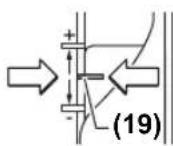
- CAtbIbI TIpeKTI (9) eH TMeHRI DeHReIe OPhaTbIHb3; CaTbIbTIpeK Iepty Dbl6bcIMeh TipeNi.
-TepehikweKteriwiHderi
(14)6ypaHdaHbI (15)TepeHikweKteriHi (14)ePkIH XblnKtBihd aetin 6ocatbHb3.
-Kyblntah6ocaty nHtiperih(23)apTKa Htepin,koFapfbl ppe3ahb bany TEmen Kypri3iH3, ppe3a (5) daBnHaMa 6etHe THOI TIC. Kyblntah6ocaty nHtiperihn NO3nucRbH Bekity yWIn OHbl (23) KaTaNocatbHbI3.
-TepehdkwekeTeri(14)catbbltipekte(9)typfaHwa TEmeHkapai6acbHb3.
GOF 1250 LCE: caHbIK TepeHik INHdkaTOpBH aKbipAtkbI (18) apKbIbIKocbIHb3. (16) TYMeciH bacIn, TepeHik WekteriHINH (14) HndIK HkyTeciH opHaTbIHb3.
GOF 1250 CE: KopceTkiw 6enrici 6ap kankbIHTbl (27)
fpe3epney Tependiin, wkanacbiHda (26) 0 KyiHe
OPHaTbIHb3.
-Tepehikwekteriin(14)kanaybIdppeepney TepehirineopHaTbIn,TepehikwekteriHneri(14) 6paHdaHb(15)TapbHb3.
GOF 1250 CE: KepcTeKii6Benrici 6ap XanKbIbTH (27) eHJI KblkBImaTbIHDbIfBa HKe3 KeTki3iH3.
-Kybnitahbocaty nHtiperin (23)6acbin,xofapfbi ppe3aHbEHKOFapFkyreKeTiptiH3.
Tepehipek pfesepney yuin apkaibcibihin pfesepney
tepehdirin Tomehipek ophaibn, 6iphewe pet opbihan ety
kepe. Catbbl tripek (9) Kemerimeh pfeseepney npocecin
6iphewe catbifa bnyre 6oana. On yuih pfeseepney
tepehdirin catbbl tipektih en TemeHri catbcimhen
ophaibn, 6ipihwi xmybc 6epinitepi yuih xofapbipak
catbnap TaHaHb3. Catbnap apacbiHaB KaWbIKtBtB
dAnen peTey 6paHdaapanbH (10) aHaHbipy apKbIbI
e3repty6oana.
CbHaK KypicTeH KeiH pfpeepney TepeHdiH aHaHaMaIbI peTteriTi (25) bpy apkbln KaKcETTI eHWeMRE dAnen petteyre 60ana; pfpeepney TepeHdiH apTbpy yuih petteriTi caF tiniH, 6aftbIme, an pfpeepney tepeHdiH a3aHTy yuiH petteriTi caF tiniH, 6aftbHa KapcbI bpaah. 1kana (24) 6aFapay yuih naDanaHbIaNbI. Bip aHaHbIM KOHdbPfbHbH 2,0 MM KypiciHe T, WkAnaHbH (24) actbHfB JxneriHderi bip 6oik KOHdbPfbHbH 0,1 MM KypicHe T. MakcmaIbI pettey Kypici ±8 MM KypaIbI.
Mbican:KaKeTl fpeepney tepHdi 10,0 MM 6onybkepek,cbHaK fpeepney KeiHne9,6 MM WAmacbHdArblfpeepney tepHdi r anbHdb.
-ⅢkaHb(24)0MaHHe6ypaHb3.
-AHannablyTytKaHbI(25)0,4MM/46nIKuMaacbHa(iC Ky3iHerjxHe6BnrlneHReHmApacbHdAf bAibpMaBblk)cafTINHH6aFbTbIme6ypaHb3.
-CbHak fpeepneydi kAnfactbpy apkbnb TaHdAnFaH fpeepney TepeHirIH TeKcepiH3.
160|Ka3aK
GOF 1250 CE: ppeepney Tepehdirin petterehnkeih kkanbbltih (27) KyiH Tepehdkwekterihi (14) oan apby e3repTneH3, coHa aKanaaFb (26) aFBIMdaFbl ppeepney Tepehdirin OKy MymkIn 6oIaIb.
GOF 1250 LCE: afbimdafl fpeepney TepeHdiI nncnneJe (21) Kepcetinei.
Paindaiany6oibinhaHcyckaynap
Φe3aIapdbI cokTbIFbcydaH XHe COKkbIaH KopFaHbI3.
Φpe3epney 6aftbMeH φpe3epney npoueci (Fcypetin KapaHb13)
Φe3epney npoecin yHemi φpe3aHbH (5) aHany 6aftbHa KapcblOpbHday Kepek (Kepi Ko3raBlc).
Ko3faIbIc 6aBbITbIMEn (CnHXPOHdbI Ko3faIbIC)
fpe3epney Ke3iHne 3neKtp KypaIbIH KOImEH Kypri3yre
60anaIbI.
Kaketti ppeepney tepenirih peTehi3 (kapaht, Kecy tepenirih opnaty, Bet 159).
Φpe3acblOpHaTbIiFaH 3JIeKTp KypaIbIh EHNDeIeTIH DaBbIHdAmFa KOHbIN, 3JIeKTp KypaIbIH KocbIHbI3.
Kynbntan 6ocaty nHtiperih (23) apKa bacin, KofapFbl
fpe3aHbTipek TaTacBHa (13) Kapai TipeReHwe
kblkbhtbH3. Batby TepeHdiRiH 6eKiY yuiH Kybntan
6ocaty nHtiperih (23) kaTa xibepiH3.
Φpeepney npoecin 6ipkeki anfa Kblkblty apKblbl opbHdaHb3.
Φe3epIey npouci aKaTaNFaH coH, KOFapFbI ppe3aHbI eH KOFapFbI KYIre KaITapbIHbI.
3nektpkpaibn eipinj3.
Kemekwi tipekenen ppeepny (G cypetih Kapaib3)
YInKeH daBnHdAmanapdbI eHDey yuH,MbICaJIb,OBIKTapdbI pfeepny Ke3iHe,TaKaTahH HeMece nHaKHaBH KEMeKUtipeK peINHe6ekITn,ocbi TIpeK 6oBIMen fpeepnyre 6oanaJb. XofapFbI pfe3aHbCbIPry TaKtacblHbMaBicKaH KaFbIMe KEMeKUtipeK 6oBbIMe KblNkBTbIHbI3.
KneKeTpdi HeMece npofoNbdi pfe3epny
NapannbTipeKc3XkneKTePdiXaHe npOdbepdi
ppeepny Kezihde ppe3a 6aftTtAfbIu WeTMObHMnEHemee shAPNIi NOUHNHKNEN Ka6dbkTanybi KepeK. KocBnFAh 3NeKtp acnAnTb6aftTtAfbIu WTeMObIH Hemece shAPNIi NOUHNHKn DaBbHdAmAHbH EHNDeTIn XHerIHe tipenTeIN de etin KObHbI3.
3NeKtp KpyanbH daaBHaDama Weti KaFaIa B6acapbHb3 COhBMeH Katap, TIK 6ypbTbKOblbYbH KaDaFAnaHb3. KaTbKYU TycipRe HKaAJaDa daaBbHdAma Xneri 3aKbMdaHyb MyMKH.
IapannenbTIpeKneH pfeepney (HCypTei KaapaB13)
Iapannenbipekti33)6afttaybiHkapHaKTapMeH (34) TipeK TaTacbHa 13)XblnKbItbn, OHbl 6pyaHdnapMeH (7) KaKETTI eHMeHcAKeC TaPTbHb3.
(36)KHe (35)KaTnapbIb 6paHda napbHbH KMeRimEn napaannelb TipeKTI y3bIHbIK 6oHbIMe KocbIMa peTeyre 6oanaJIb.
AHaMaBtTyKaHbH(37)KemErimeH eki KaTnApbl 6paHaHaHbI (35) 6ocatKaHHaKeiY3bHbIKbTdAnDpeTteyTe bOaNJIb. Bip aHaHaBIM KOHdbIPbHbH2,0 MM KypicHe TH, aHaHaMaBt TyKaHaFbI (37) 6ip 6eNik KOHdbIPbHbH0,1 MM KypicHe TH.
TipeK nHaKacbl (38) apkblnbpapanenb tipeKTHmIdi TipeK 6etih e3repyre 6oana.
Kocbnfah 3neKtp KpaBbH bipKeNk i anFa kapa Jypcneh
JHe npaannelb tipekti ByiPiHcN KyCy apKnbl
daBbHdama KneriHH BoBIme Hxprizhi3.
Napannenb typekneh (33) pfpeepney kezihne wah/koHka copy apeketin ahpahnb copy aanterpi (39) apkbbl opbHday kepek. Copy aanterpin opHaBnFaH Kynde KaNbbypa60ana.
UnpkybmenΦpe3epny (kepek-kaPAK)
Anrenek6nweKeTpdi ppeepnyuin npKynbni naananahyfa 6oana.
BaftaybuiuHHaMeHΦpeepny (kepek-xapak)
BaftaybuiiHnHaBHyXaHe 6aftaybuiiHnHa aadantepinH Kemerim Hik kyyepih XyMbic npoecTeipnOpbHdayfa 6onabbl.
Kowipy rmb3acbImeH fpe3epney (I-L cypeTepin KapaHb3)
Kewipy nIb3acBHBH (43) Kemerimeh KOHTypapdby yrrinepe MHea6nohdpadHa daBHdamaTycipyre 6oana.
Kewipy rnh3acbHwa6noh HeMece ynri KaNbHbIbFbHa cNkec TaHaBbI3. Kewipy rnh3acbHbH WbIFbT pyaBH 6NIKTiriHe Hwa6noh KaNbHbIbFb8 MM-DeH KEM 60mMayb Tnic.
Kewipy rInb3acbH (43) KondaHy ywiH andbimEn Keiipy rInb3acbHbH SDS aanTepH (40) cbipy TaKTacbHa (11) eHri3y KaKeT.
KωiPy rIb3acBHH aanTepiH (40) xorapbdaH cbipry TaKTacBHa (11) ehrisin, 26ekitkiw bpaHamaH (41) bypan 6ekitih. KωiPy rIb3acBHH aanTepiH kynbintanb6ocaty nHtiperHH (42) epKH XblNky MymkiHirH kanaFanaHb3.
Kyblntah 6ocaty nHtiperH (42) KepcTeK 6aftbImeH Xblkbltn, KeWipr rnlb3acBn (43) acTbHfJxakTah KeWipr rnlb3acBnH SDS aananepine (40) eHri3iH3. Byn pette KoTay KdyibpkiuanaPb KeWipr rnlb3acBnH (43) caBnaynapbHa a3daar H Kywnen 6ekitinyi kepe.
Φe3a optacbMeH Kωipy rnlb3acbHbIH KHeiHEn apakawbIKbIKbTeKcepi3 (kapaHb3 ,TipeK taKTacbH opTafa KeItipy (N cypetIH kapaHb3)”, Bet 161).
Kowipy rnh3acbHbH iWKi dHaMeTpineH Kii 60aTbH ppe3a dHaMeTpH TaHaHbI3.
Φpe3epny npoueci
Keuipy rnh3acbi (43)6ap kocynb 3neKtp KypanbH wabnoh 6oBnHaXyprisiH3.
Kynbntanbocaty nHtiperin (23)apKa bacn, KofapfbI pfe3aHb6enrIneHnpe3epny TepeHirine XetKeHwe 6any TEmen Kapai KblkbTbHb3.Batby TepeHirin6ekity yin Kynbntanbocaty nHtiperin (23) kaTa xibepi3.
IbfbHkbk Keipy rnh3acbi (43) 6ap 3neKtp KpaBbH 6yipin Hkbcy apkblbwa6noh 6oibmeh Kypri3iHa.
TipeKaTacbIH optaKentipy (N cypetIH kapaHbI3)
Φe3a optacbHaH KeWippy rnh3acbHbH KneriHe deinHri apakaBkTbK 6ipde60nybl ywiH,KeWippy rnh3acbH (43) XHe cbIPy TaTcBtH (11) KaXeTIHwe 6ip-6ipHe optara kentipyre 6oIaBl.
Kynbntah bocaty nhtiperih (23) apka bacin, kofapfbl
pe3aHb Tipek TaTacbiHa (13) Kapai TipenreHwe
XbNkBtBbIbI. BAtbpy TepeHdiir 6eKiy yuH Kynbntah
bocaty nhtiperih (23) kaTa xibepiHj3.
Bekitkiw 6ypaHdaapdbi (44) cbipfY taKtacbi (11) epkih K03faIaTbHdA wAmMeH 2 aHaIbIMFa 6ypan 6ocatbHb3. Optara dAnpey kKaTayBH (45) cypTe KepcetireHeJey BekitkiWHe opHaTbHb3. CanMaJIraKahBI optara dAnpey kKaTaybI epKII aHaIaTbHdA erin TapTBHb3. Optara dAnpey kKaTayBH (45) Xe He Keuipy rInb3acBH (43) cbipfY taKtacbi (11) kiUkeHe Xblkblty apkblbl 6ip-6ipimeH typalaHb3.
6ekitkiw 6ypaandapdbi (44) kaTanaH 6ypan 6ekitih3. Optara dAney kakTaybH (45) Kypan 6ekitkiinHe H ibFapbHb3.
Kyblntah 6ocaty nHtiperin (23) 6acbln, Kofapfb1 ppe3aHb1 eH KOFAPfkyre KeTIPiH3.
Batapehbl aybictbipy (GOF 1250 LCE) (M cypetin kapa h3)
Batape 6eiminH KKaNaFbH (22) XorapbI Kapai
XblnKbItbH3 Xhe 6atapeHbI bIfapbIn aIbHb3. KaHa
6atapeHbCaIbH3 (CR2032 Typi). BatapeHbOH
nonici 6atape 6eiminH KaNaFbHa (22) KaTbcTb anFa
kapan typyBepeK. TbIb3daybiWtB (46) cAlbn, 6atape
6eiminH KaNaFbH (22) Xaybn KOybHb3.
TexHnKaIbIK KyTIM XHe KbI3MeT
KbI3MeT KOpCeTy KHe Ta3anay
BapnbKxmbCTapdaH andbH 3neKtp KypanbHbH Xeninik aHbpiH po3ETkadah WbIFapbHbI3.
Kakcbi api cemimdi xymbic ictey yin 3neKtp KypanbmeH KeJETKiTecikTI Ta3a YCTaHbI.
TToTeHWe JxMByC XaFdaBbIHdMa MymKIn 6oNfAwa
WahCOPfbIITb naDanaHbIb3.KeNdtkiu
OyIKTapdbXaKaBbIwneH XnTa3anAn, XbINbICTay
TOBHaH KopraTbH KocBbIHTb (PRCD) anDbH ana
KocBbI3.MeTaNapDbEhderE He3e, TOK eTKi3etIH
UaH 3NeKTP KypaBbIHbIH iUHHe XHaHanybl MyMKiH. 3NeKtp
KypaBbIH KopFaBbIH OKaaynaftbI b3aKbIManybl
MYMKiH.
Erep 6aIbHc bIMBH anMactbpy kaxet 60nca,
Kayinci3dIKTH TEmeHdeyIHe KOn 6epMey yuHIn Ocbx KyMbIC
TeK Bosch KOMNaHRCb HeMece Bosch 3neKtp KypaNapbl
6oBbHHa aKeIeTTi KbI3MeT KepeTy optaIbIKTapbHda
KyprizinyTnic.
Ohimdepoi onapbi KaTbIbfi KaMTamcb3 etetih,
ehimdepre atmocepaibik kaybiH-uaibHHbTHIOHe KHe
ackbi TEMpepa TKe3epiH (TEMpepaHbIH WYfbi
e3repiciH), coBH iWHe KYH cynenepinH acepetyihe
KoJI6peMeTIN DyKeHdEpDE,6eIMdEpe (ceKuHaapda), naBnboHAp MeN KNOCKInepDe cAtyfa 6oNabl.
Catyubi (eHdpuyi) catbin anyuubifa eHimdep typabkaxetti xhe bHaahb aknapaattb6epin, eHimdepTnicihwte TaHday MymKHHIRIHN KAMTaMaCb3 etYe MiHDetTI. EHMdepTypabaknapatMiHdetTI TypTe tisiIM Pecei FedepaunacbIHbH 3aHaMaCbIme6enrineHReMJIIMETepdi KaMTybl Tnic.
ErepTybHuybCatbn anaTbH eHMdep 0Jekaawan naDanaHbInFaH Hemece eHMepde akaynbk (akaynbkTap) KOblFaH 6oNca, TybHyyfa 6yI TypaIbI aknapat 6epinyi Tnic.
EHIMdepn caty npouecinH aacbHna TEmeHneri kayinc3dk TaanTapbOpbHdaIybiTic:
-CatybIcTbnanybIfaYbIMbHbINdmpMaBbK aTaybl, ophanackanKepi(MekeKaNbi)Xane XymbcpeKmI typabImimetepbepyreMiHdetti;
-Cayda6emepinderiHIMdepiHcbHAMapbCatbanybifa 6yibmnapaFbKa36anapMeH TaHcyfamMkiK6epyiKaHe BnayanTeKepicTeh6aca6yibmnapbIHckeKocbnyHaKeenetIH,catbanybnape36tihweopbHdAHTbHewkaHdAnpekeTepreXon6epmeyiTnic;
-CatybOcbl6yHbIMapDbH6enrHrenTanaTapFa cAnKeCTirHnPactaMaCbl,ceTpHnKnATpAHTbHHeMeCe cAnKeCTIKxEHINderiMaIMdEmepePiB6apBoNybl TypaIbaknapaTbCatbnanybHa6bepyreMindeTTi;
-ⅡeHTHnKauNbIK CnTtApbl JOK (KoFAJFaH), KapaMdbInbIK Mep3iIM EtIN KeTKEH, 6y3bIy6BnInepi6ap KHe NaDanaHy BoHbHa HcayNbFlb (Kitanlacbl), MIHeTTi cAnKeCTIK cepTHnKAtb HeMeCe CaKeCTIK 6nRici JOK eHmdepiCaTyfa TbHbIM CanBaHdbl.
TytbHybIfa KbI3MeT Kepcety XHe naIdaIaNy Kehectepi
Kb3MET Kepcety optanbIbI eHmDi JxHey xHe oFaH TexnHKaBik Kb3MET Kepcety, coHdai-ak KocanKb6enweKtep TpaBIs cypaKTapra kayan bepei. KypamDAC 6bnweKtep BoBHnA Keckin MeKocanKb6enweKtep TpaBIs mAnimetTep TeMeHderi MeKeHHa BOnbIHwa KonKetim: www.bosch-pt.com
Bosch Kbl3MeTtik Kehec 6epy To6bl 6i3in eHIMdep XHe OnapbIH KepeK-JkapakTapbl TypaIb cypKaTpbl3Fa Kayan 6epei.
CypakapkoXaheKocanbI6eWKeTepreTancbipbc6epy KeiHneMHDeTTTyppeEHIMHHHfmpMaBk TaKaTaHaCbHdAfb10TaHbAnbEHIMHemipih6epiH3.
Hdipyti TanaTapbMeH HopMaIapbHbIH CaKtanybIme
3nEkp KypabHxHcHeyKHe KeiNdi Kbi3Met KepCety
6apbIK MemKeTepayMaFbHda TeK "Poept Boiu
HpMaIbIK HeMece ABTopHaunHaH Ka3Met KepCety
opTaIbKTapbHdaOpbHdaaBd. ECKETy! 3aHcb3XoJmEH
ekInHRe HEmIpdi naDaAnhy KayinTi, DeHCaybIFbHb3Fa
3HH KeTIpyi MyMKH. OhIMpepi 3aHcb3Xacay XHe
TapaYakMwnik XHe KbIMbICTbIK TaPTIN BoBHwa
3aHMeN KyDalaHaBbl.
162 Romana
Ka3aKCTAH
TytbHyyBnapFaKeHeC6epyKHe WafBIMdApblKa6blday optaIbIbI:
"PoBept Bow" (Robert Bosch) KLIJC
AnImatkiK.
Ka3aKcTaH Pecny6nKacb050012
Mypat6aEBK.180y
"TePmec" BO,7 Ka6aT
Ten.: +7 (727) 331 31 00
_aKc: + 7 (727) 2330787
E-Mail: ptka@bosch.com
CepBntK Kbl3MeT KepcTeOpTaIbKTapb MeH Ka6blJay nyHKTePiH MeKeH-JaHb TypaJIb TOnblk XHe 0eKti aknapaTb Ci3: www.bosch-professional.kz pecMH caTTaH ana anacbi3
3neKtp Kpansbkiinni naDanaHy mep3imH iuiHde HdpyHHiKecipineH ICTeH WbIKKaH KaFda, OHIM nci TMeHneri wapTAP opBihdAnFaHaKeINik 6oBHua TerIH KeHDeye RkKnblb 60nla:
-MexaHnKaIbIK 3aKbIMapDbIH JOKTbIFbl;
-naDanaHy BoHbHa HcaybKa TananTapbHbH 6y3iny 6enrinepiHHKoKtbFlb;
-naDanaHy BoBbHwa HyckaynbKa catyBbHbH,caty Typanb6enricinHKeHe catbnanybkoTahbAcbHbH 6ap bonybl;
3nKtp KpaIbI cepnblk HemipinHxane Kenindik TaHObHdaFbI cepnblk HemipinCaikeciT;
-6iikci3xehdey6enrinepiHHKoKtfbfbl.
Keninik Temei deri Xaafda Napda KonlaHmaibI:
- fopc-MaKOp KaFdaNapbHa 6aHbICTb Ke3 KeIreH CblHbKTap;
-6apnblk3neKtp KpaandaepbHdaefbdaa 3neKtp KpaanbHbKaJIbINTbTO3ybl.
KaNfAfbI KONTAKTINep,cbIMap,kbINwAkap TKeH T.6. cnKbI Kypan 6nIKTePiH Kbi3MeTery Mep3iMH KbICAPTaBH KANBINTI To3y HAtNkeCIne KaKettiniri TyIHDAFAH KeHDeY KeniDik AarCbHa KipMeNi:
-Ta6HFNTo3y(peycpTbIHToIbIKnaiJaIaNbIbNybl);
KaTe opHaTy, pyKCaTcBIs MOniФnKaunay, KaTe KOJaHaY, KbI3MeT KepeTy HeMece caKay epeKepePi 6y3y HtNkeciHne ICTeH WbIKKaH Ja6bIK NeH OHbIH 6oikTepi;
-3neKtp KypalbHa apTbIK KxykTeMe TcckEnHeOpbH anFa h akaynap. (KypalFa aptbIK KxykTeMe TycyDIn HapTcbi 6enrinePi HeMbHaIap XaTaBb: Ky6blny TyCinH naJa 6onybI Hemece 3neKtp KypalbI 6enlKtePi MeH tyHepiHn DeopmaunCbI Hemece KopblNybl, KOfarbpI TempepaTy acepH eNeKtp Ko3faTTkbuHdaFbI cbIMdAp OKwayNaBbHbH KapaObl Hemece KemipEnyi.)
Kadere kapaTy
3neKtp KpybIfnApbIH, aKKyMyIaTOpnapdb/ 6batapeanapbl, KepeK-kaPakTap MeH opaybiTapbl KopwahAn opta ywiH kayinciXoJMeH KaIHa eHcy opBHa XibepyKaXeT.

3neKtp KpybIrfbnapbHxhe
aKKyMnIaTOpnapbIb/6aTapeaIaPdpI TypMbicTbIK
KOKbICKa TactaMaHbI3!
Tek kana EO endepi yuin:
EyponaBik 2012/19/EU dInpeKTHBaCbHa cAnKeC Japamcb3neKtp KpyblfNApBH XHe eyponaBik 2006/66/EC dInpeKTHBaCbHa cAnKec akaybl HeMece eckipreh aKKyMnyTopnapbl/baTapeHnApbl b6TeK kHnay XHe KopwafH opTa yWIn KayInc3 XOnmEn KaTt eHcy OpHbHa Kj6epy KaKet.
Româna
Instruţiuni de siguranta
Sistemul electronic constant
Sistemul electronic constant mentine turatiaaprope constanta la fonctionarea in gol si sub sarcina, asigurand un randament uniform de lucru.
Pornire lenta
Service sculelectric
Strada Horia Macelariu Nr. 30-34, sector 1
013937 Bucuresti
170|BbIgapcKn
GOF 1250 CE: BHIMaBaiTe Da He H3MeCTBaTe NOBeYe NJIb3raUc a MApKnPOBkata (27).
- HatncheIocTa3aOTKIOUBaHe (23) INpekapaTe 0epepe3ata B HAI-TopHa I03nui.
Pnno-rolemn Dnb6oHHn Tp6Ba da n3BbPwHte ppe3ObaHeto HA HAKONKIO PPOXODa C NO-MALIKN CTbKN. C NOMOHTA HaCTeNEHHNOrpaHNUHTEN (9)MOxETe Da pa3DeJIte NPOeCAHaΦpe3OBAHe HA HAKONKIO CTbKN. 3a CEENTa YCTaHOBeTe KeIaHATA Dbl6OuHHa HAΦpe3OBAHe C HAI-HNCkATA CTeNEHHaCTeNEHHNOrpaHNUHTEN i CNEI TOBA I36epeTe 3a NpBPNAPOXOD cbOTBEtHO HAI-BNCOKATA CTeNEH. PA3CTOHNTo HaCTeNEHNTe MOxE da 6bJe IpomehHO C NOMOHTA Ha peryINpaUHTBE (10).
Cnei np6ho fope3oBaHe moKeTe da hAcTpoTe bIb6OuHaTa Ha fope3oBaHe ToUHO ha JeenaHn pa3Me pye3 3aBbPtaHe Ha pbKOBxBatkata (25); 3aBbPtaHe NO nocKa Ha acOBHNKBoBA tCTpeNka BOAn Do yBeNnuBaHa He nb60uHnata Ha fope3oBaHe, CbOTBeTHo o6paTHo HA cAcOBHNKBoBA tCTpeNka -do HamaJraBaHe Ha nb6OuHnHa Ha fope3oBaHe. Pnp pery
InpaHe MoXeTe Da H3No13BaTe cKaIaTa (24).EINH O6OpOT CbOTBeTcBA Ha XoJ 2,0mm,eHa OT YeTnPte KbcN IINHH B RopHna KpaHbTynkata (24) CbOTBeTcBA Ha N3MeHHeNe ot 0,1 mm.MakCImaJIHTo H3MeHHe NaNbIo6OuHATA Ha φpe3ObaHe e ±8 mm.
Ppimep: Dbl6oHnHa Ha fpe3oBaHe Tp86Ba da e 10,0 mm, npn np6hTo o pfe3oBaHe ce nolyu Dbl6oHnHa 9,6 mm.
-3aBbPTeTeCKaJaTa(24)Ha0.
-3aBbptTe pbKoXBaTkata (25) c 0,4 mm/4 deneHna (pa3Nkata OT HOMHaJIHaTn DeiCTBnTEHnTa nbl6ouHa) NO NOCOKa Ha YacOBHNKOba CTpeKa.
- PpOBepeTe HOBaTaNbIbOuHnC NOBTOpHO npo6Ho 30BaHe.
GOF 1250 CE: CnEh NactpoBaHe Na IbIb6OuHnTa Ha ope3OBAHe He n3MeHnIte No3nIyraHa Na IIb3raUa (27) Ha IbIb6OuHHnIg ORpaHnUHTeI (14), 3a Da MoKTe BnHaRn Da OTTuTate MOMeHTHata Ib6OuHnHa o ppe3OBAhe NO cKaIaTa (26).
GOF 1250 LCE: MOMeHTHa TcToHocT Ha dbl6OuHHaTa Ha Φpe3OBAHe ce noka3Ba Ha dncnne8 (21).
Yka3aHn3a pa60Ta
PpeNa3BaIe 0yapn npesKn HatoBapBaHHa.
Tocoka H npoec Ha ppe30Bahe (Bx. mF)
Φpe3OBaHETOp46BaJaCeN3BbPbWA BnHaRnB NoCOKa,obpaTHa HbBpTeHTo HaΦpe3epa(5)(npoTHoNoXKeHxO).PiuΦpe3OBaHe BCbUata NocOKa (eHNOcoUeHxoJ) eNEKtponHcTpMeHTbT MoKe da 6bJe OT-KbchatOTpbUeTE Bn.
HactpoiteKeenaHaTaNbB6OuHaHaΦpe3oBaHe(BK.HaTPOiKaHaNbB6OuHaTaHaΦpe3oBaHe",CtpaHua176).
IocTaBeE nekTPOHnCTpyMeHTa CMOTnpaH fpe3ep Bbpxy 6pa6oTBaHHn DeTaN Iro BKIOUeTe.
HaTNCHeIIOCTa3oTKnIOUBAHe(23)HaDOnyHnpeKaapAte 0ebppe3ataOynopBnocokaOCHOBHATAIIooua(13).OTnyCHeTe OTHOBOCBO6OxDaBauniaNt(23),3a daΦnKcnpate Ta3n Dbl6OuHa HcnyCahe.
I3nHHeTeΦpe3oBaHToC nOcToaHNo nOdaBaHe.
CneipnKIOUvaHe Na Ipoueca HaΦpe3ObaHe BbpHTe 06epe3aTBAH-nrOpHa nO3u.
N3KIIouTe eNeKTponHcTpymeHa.
Φe3oBaHe c nomouHa onopa (Bx. fhr. G)
Ipn6o6p6oTBaHe Ha rolemn DeTaHIn, Hap. npn 6pe3oBa- He Ha KaHaIn, MoKTe Da zakpeNITE KbM o6pa6oTBaHHaDe TaHbCKa HINu SHHa KATO NOMOua HOnopa nDa BOHte O6epe3ata No DlnJHKnHaTaNBoTe O6epe3ata OT nIOckata CtpaHa Ha aHTINΦpHKUHOHnA TnOua No DlnJKNHa- Ta Ha NOMOHNr ORpaHnHTeN.
Φpe3oBaHe Ha pb6OBe/Φpe3oBaHe no npoФn
PnFpEe3OBeAne Pb6 nHn no npOoHn 6e3 npCncOc6Ne HnE 3a ycnpoeDn BOeHe ppeepbT Tp6Ba Da HMa BOeU uNt Hn TbpKanJn aReP.
IIOBBeTe BKNIOHcHEnENEKTPONHCTPymeHT CTAHNHO KBM 06pa6oTBAHHaTeaIN,DOkato BOeHnT UHFT HnNArepebTa HaΦpe3epa Donpe Do o6pa6oTBAHHpb6.
BoTeEneKtpOnHCTpyMeHTa yCnpeDHO Ha pb6aHa Detai Na. PnTOBa BHIMABaTE Da He IpOMeHrte HAKIOHa My.
Tbpe CnHOTnpHtckaHe MoKe Da NOBpeH p6a Ha TaIa.
Φpe3oBaHe c onopa 3a ycnpoeHbOdeH (Bx. fhr.H)
BkapaIte onopata 3a ycnpedno Bodehe (33) c HanpaBnBaunTe 34) B OCHOBHATA NIOa (13) n a 3aterHete CBNHTOBeT (7) Ha XeJAHOTo pa3CTOHHne.
C KpnIuATHe BHTOBe (36) H (35) MoXeTe Da HaCTpoBate onOpTa 3a YcNopeHDo BODe He ObJIHNHTENHO No DblJxHa.
C BbpTnata ce pbkOxBaTka (37) MoXe Tcne pa3BnBaHe Ha DaBATA KPNUATN BHTA (35) da perynnpaTe bJnxHata fno. Ipn ToBa Ha eHN HOBOP CTbETCTBa nPOMHa Ha dbJnxHATAOT2,0mm,Ha eNO deneHHe HA cKaIATA Ha pbKoXBaTKata (37) CbOTBeTCTBA Ha npOMHa OT 0,1 mm.
C onophata WnHa (38) MoKeTe Da npomehrte eefkTHBnA tOnOpHa NOBbpxHOCT Ha ONOPaTa 3a ycnpoeHbOBeHe.
BoTe BKNIOUeHnEneKTPoHHCTpymENTcpaBHOmePNO OaBaHaHe nCTpaHnHo pNtncKaHa H npncNo6JeHneto 3a yCnpoeHbOBeHKeMb pb6aHa o6pa6oTbAHn DaTaI.
PnΦpe3oBaHe C onopata 3a ycnpoeHNO BOeHe (33) npaxoynaBHeTo/ynaBHeTo Ha cTpyKKn Tp8Ba Da ce N3BbpiBa C NOMOHTA Ha cneuaHnHa aanTeP 3a npaxoyNaBHe (39).AanTePbT 3a npoxoyNaBHe MOKe da OctaHe MOHTpaH.
Φe3oBaHe c aadantep-nepren (npnHaIeJxHocT)
3aфpe3oBaHne no KpbroBa IbRa MoKTe Da H3noJ3BaTe aanTepa-nepren.
Φe3oBaHe c HnnpaBnBaWa 1HnHa (pHnHaDneKxHoCT)
C nOMOuTa Ha HApBaJIBaUaTa ⅢHa HHa aIaJItePera 3a HApBaJIBaUa ⅢHa MoKeTe Da Φpe3OBaTe No IpaBAIINHn.
Φe3oBaHe c KOnnpaua Btynka (Bx.Φnr.I-L)
C nOMOHTa Ha KONHpaUaTa Btynka (43) MoKTe da npehaCte KOHTypuTe Ha MaKeTn, pecn. 7abloHn Bbpxy o6paobBaHna DeTaN.
H36epete noDxOJa KaONpaAa BtynKa 3a De6eHNHaTa Ha 1a6bNoHa. Iopadn DblNHaT a Ha NpdaBaHe Ha KOnpaaata BtynKa 1a6bNoBt Tpr6Ba Da HMa MNHmAlHa De6eHNHa OT 8 mm.
3a n3no13BaHe Ha KOnpuaaTbTyNka (43) npednTOBA Tpa6ba da ce noctabn SDS aandaTepe ha KonpuaaTa BtynKa (40) bAHTnDppnkunHnHaTnOua (11).
Iocabete aanterpa ha konnpaata Btyka (40) otrope Bbpxy aHTnphiKUHnHa TIOOa (11) n ro 3aBnTe c 2-Ta 3aKpenBaun 6oTta (41). BHIMaBaIte NoCTb 3a OTKnIOuBaHe 3a aanterpa Ha konnpaata Btyka (42) da ce DBHXn Cbo6oJHo.
HaTnCHeTe NoCTa 3a OTKnIOUcBaHe (42) nOncOka Ha cTppenKaTa HocTaBeTe KOHpaAata Btynka (43) OTdOny B SDS aAnTepeHa KONHpauata Btynka (40).PiN ToBA KoHpaAunTe Naun Tp8Ba Da nonaHaT B npedBnEHeNe 3a cenTaOT
BOPN B KONIPAaTa BTyIka (43) cOTyETnBO nppepaKaBa-He.
PpOBepe pa3cTOnHHeTo O cpeData Ha ppe3epa Do pb6a Ha KONnpaata Btynka (Bk. ,LcHTnpahe Ha oCHOBHata nloha (Bk. qnr. N) ,CTpaHnca 177).
H36epete ppeepc no-MaBk DnAmetbp OT BbTpewHHaDnAmetbp Ha KOnHpaaata BTynKa.
PpoecHaΦpe30BaHe
DontpeBkIoueHnEneKtpOnHcTpymeHT c KOnnpaata Btynka (43)do wa6noha.
HaTHCHETe Ha3aOcBO60xJaBaAuaNIOCT (23) H6aBHO cnYCHETe ObePpe3aTHaONy,doKATO DCOTnHETe HAcTPOeHATA bIb6OuHnHa hpe3oBaHe. OTYNCHETe OTHOBOOCBO60xJaBaAuaNIOCT (23), 3a DaΦHKcnpate Ta3n Dbl6OuHnHa cnYCKaHe.
BoJeTe eNKeTPOINHCTpyMeHTa cNoDABaUaTa ce KOnnPaua BTyIka (43) no npoPhna Ha 1a6NoHa cbc cTpaHnHo npnTHCKaHe.
UeHTpHpaHe haochOBhata nnoa(Bx.ΦnR.N)
3a da 6bde pa3c0rHHeTo OCTa HaΦpe3epa Jo p6ba Ha KONHPaUaTa BTVIka EaHAKBO BB BCNUK NOCOK, KOINpa- uata BTVIka (43) nAHTnFpHKuHOHaTnloa (11) Tpr6Ba npn Heo6xOIMocT da 6bdat CEHTPnpAHn EHa CNPMA Dpyra.
HaTnCHete NoCTa 3a OTKnIOuBaHe (23) HADONY nIpeKaapae Oebppezata DO ynpoB NocOKA OCHOBHATA NIOUa (13).OTnycHete OTHOBOCBO6OxDaBaUNaHnIoCT (23),3a daΦHKcnpaTe Ta3N DblbOUnHa NaCnyCaHe.
Pa3BnIe BnHTOBete CnnHnDpHnTnabn (44) Ha OK.2 06oPota, Taka ye aHTnDpHKnOHnHaTnOa (11) da MoKe Da ce dBnKn Cbo6oNo.
IocTaBeTe CEHTPnPaAaH DOPHNK (45) KaKTo e NOKa3aHo Ha H3O6paKeHHeTO B NOCTaBkATA 3a HhCTpyMeHT. 3aTeHHeT aPbKa XoJIeHDPoBaTa raiKa, Taka Ye CEHTpnpaAaH T DOPHNK da MoKe Da Ce DnKn CBO6oJHO.
IopapBHeTe CEHTPpAunI DOpHnK (45) n KOnnpaata Btynka (43)upe3NeKO n3MeCTBaHe Ha aHTnΦprNKuOHHaTa nnOua (11).
3aTeHHe 3aKpenBaunte 6oTObe (44) oTHOBO.
OTcpaHete CEHTpnpaunI DOpHnK (45) OT NoCTaBkata 3a HNCTpyMeHT.
HaTNCHeIIOCTa3aOTKINHOBaHE (23) IN ppekapaiTe o6eppe3ata B HAI-TopH aNo3nua.
CmHa Ha 6aTePnra (GOF 1250 LCE) (Bx. fHr.M)
I3meTe Haorope KaNaka Ha rHe3dOTo 3a 6aTePnN (22) n I3BaTe 6aTePnTa. NocTabeTe HOBa 6aTePnN (TN CR2032). IIOJXHTeHnTt NOnCtHa 6aTePnTa Tp8Ba Da e o6bPaHa Ta KbM KAnaka Ha rHe3dOTo 3a 6aTePnN (22). NocTabeTe yIbTHnTeN (46) n3aTbOpTe KaNaka Ha rHe3dOTo 3a 6aTePnN (22).
PoiDlbpxKaHe n cepBn3
IopdbpxaHe n nouHCTBaHe
PpeHn3BbPwBaHe Ha KaKBtO n Da e DeHocTn no enEeKTPoHnCTpyMeHTa N3KnIOuBaIte UeNcena O TaxpaHbaaTa MpeXa.
3a da pa6oHTe KaueCTBeHO 6e30nacHO, noDbPkaIte enektpoHcTpymEnTa H BENTnlauOHnTe MyOTBOPN uCTH.
N3no3BaIe npEekTpeMHyCNOBnaHa yNtpe6aNo Bb3MOXHOCTBnHn H3CMYKBAua Hnctanaa. Pe- DOBHO NOuHCTBaIe BEHTNaUHOHHTE OTBOpH C YeT Ua H NOn3BaIte DeepkTHOTOKOB PpeNa3EH PpeKbcay (PRCD).Piouo6pOtaHe Ha MeTaNIO BbTe peHocTa Ha eNEKtpOHnCTpyMeHTa MOKeJa ce OTNOxu TOKOpOBexJaAn npax. Toba MoKeJa HApuyN 3aunTHata H3OlaunHa eNEKTPOHnCTpyMeHTa.
Korato e Heo6xOHa 3aMHa Ha 3axpaHbuaa Ka6en, Tn Tpba Da ce N3BpuN BOTOpnIpaH cepBn3a eEeKTPoHCTpyMeHTn Ha Bosch, 3a Da ce 3aNa3n HNBTo Ha 6e3onacHOCT Ha Bosch eEeKTPoHHCTpyMeHTa.
KnneTcKa cnyk6a H KOHCyNTaunr OTHOCHO ynotpe6ata
CepBn3bT ue OTROBOpH a BbnpocHTe Bn OTHOCHOpeMOHTn I noDpBkKa hA 3akynenHr O T Bac npOyKT, KaKTo HOTOCHo pe3epBHNu cactN. POKOMNoHEHTH N cepTeKn HnHΦopMaZua 3a pe3epBHNte qactn ue OKPneTe Ha: www.bosch- pt.com
EkntnoKCHcyntaOnOTHOCHOyntpe6ataHaBoschue Bn NOMORHe C yIOBOCTBNE npn Bbnpoc3a HauHTe npoDyKTINTexHNTe akcecoapn.
Moi, npBbnpocn npnpopbyBaHe Ha pe3epBHN qactH BHHn nocOyBaTe 10-undpeHnKaTANOKeH HOpE, n3nnCah Ha Ta6eKataHa ypea.
Блгаря
Robert Bosch SRL
Service scule electric
Strada Horia Macelariu Nr. 30-34, sector 1
013937 Bucuresti, Romania
TeN.:+359(0)70013667(BbIrapckn)
a c + 40212331313
Email: BoschServiceCenterBG@ro.bosch.com
www.bosch-pt.com/bg/bg/
Бракуван.
C orne ona3BaHe Ha oKoHnHa Tcpea enektpnuecknte ype- n, obuKHOBeHnTe HnAkyMynatOpHn 6aTeepn, donbHnTeHNHe npHaadJeXHoCTn OnakOBKeTep8Ba Da ce npedaBAt 3a OnoNtOBoPraBeHa Ha CbDpKaaHTe Ce B TEx cypoBHH.

He n3XbPnIte enektpnuecknTe ypeDu n akymyIaTOpHnTe 6aTePN/6aTePNtepnTe npn 6ntoBnTe OTnabu!
Cama 3a cTpaHH ot EC:
CbINaCHO EBPoneckata DnpeKTHBa 2012/19/EC Beue HeH3NON3Baemnte eeneKtpoyepei, a cbINaCHO EbponeckataDnpeKTHBa 2006/66/EO deΦeKTHnte HnN 3paXoDbAHnakymlaTopHN batepnn Tpr6Ba da ce cb6npaT pa3dEnHO nda Ce npedaBt 3a ekONOrnHo peuKnnpahe.
MaKeDoHcKn
Be36eHocnHaNoMeHH
OnuTH npedynpeyBaHa 3a 6e36eHocT a eNektpnHn anatn
PENEY-PENYBAHbE
PpOHTajTe rH cHTe 6e36eHocnnpedynpeyBaHa, nHyctpaunn CneuФнkaun npinoKeHN co
OBJeIeKtpnueH anaT. HenpIpxyBaHbeto Do cHTe ynaTCTBa npINOxKeH nOIOny MoKe Da IOBeE Do CTpyEH yap, nokap H/nnI TeuKn NOBpeH.
3auybaje rn 6e36ednochntpeynpeybaHa n ynaTcBA 3a KopncTebe H3a BO HdHHa.
Pnonmot,eneKtpnueH anaT Bo 6e36ednochnte npEynpeyBaHa ce odNecyBa Ha eNcKtpnHn anapatn wTo KopncTAT cpyja (ka6enckn) nn anapatn wTo KOpHctat 6atepn (akymnatopcn).
Be36eHnOcHa pa6oTHnOT npocToP
Pa6oTHnOT npocTOp oOpyBaJte ro uHCTn Do6po OCBETnEN. IpenoJIH nIeTMn npocToPm MoKe da DoBeaTdo Hepeka.
He pa6oTe co eNEKtpnHHTe anaTH BO EKcNIO3NBHa OKOINHa, KAKo HA npHMeP, BO npCycTBO Ha 3anaHbN TeuHOCTH, rACOBH HnnpaHHa. ENEKTPnHHTe anaTH CO3daBaat NCKPN KOHtO MoKe Ja ja 3ananat PpaHHata HnIraCOBHTe.
DpKTe Tn deaTa n npCytHne noaneky doKe pa6oHTte co eeneKtpueh anat. HeBHMaHHeTo MoKe da npedn3BnKa da n3r6bnte KOHTpOna.
EneKtpnHa 6e36ednoct
PnPKnyOKoHa eNEKTPnHNoT anaT Mopa da OndroBapa Ha npKnyHnUaT. HNKorau He ro MeHyBaJte npKnyOKo. He KopncHTe npKnyuHa aadTepn Co 3a3emJeHnte eNEKTPnHn aIaNTH.
Hn3MeHeTne npKnyOuOn n COoBBeTHnTe pNknyuHnUTo HAmJIyBaAT pn3NKOT OJ CTpyeH ydap.
M36erhybajTe TeneceH KOHTaKT co 3a3emjeHH NOBpuHH, KAKo Ha npMep, ueBKN, paJnaTOpN, METAHn Hauu N Naunnnu. IocToI 3rOJeMeH p3NK Od cTpyeH yap aKo BaWte To TeNo e 3a3emJeHo.
He H3noxybajte eneKtpnHHTe anaTH Ha doxk Hn BlaxHH yCNOBn. Ako Bne3e BOda BO eneKtpnHNT aanT, Ke ce 3rOlenmu nIKOT od cTpyeh yap.
He noctanybajte hecooDBetHO co Ka6enot. HnKoraw He ro KopnCTeTe Ka6enot 3a Hocebe, Bneuehe nn NcknyBaBe o CTpyja Ha eNEkTPnHnOT anat. Ka6enot yuBAjte ro nOdaNeky oD orAn, MaCNo, ocTpni HBnHnn NOBxHH DenOBn. OWTeTeHNn 3aanTkaHn Ka6nI r 3rOJeMyBaAT pN3NKOT oD cTpyeh ynap.
Pn pa6oTa co eNeKtpuH enaHa otBopeHo, KopHeTe IpoDOnJxH KAben CoOdBteH 3a HAdBopeHa yNoTpe6a. KopHeTeHbTo Ha Ka6en COoDBeTeH 3a HAdBopeHa yNoTpe6a ro HaMaIyBa pNikKOT Oi CTpyE hYap.
Ako mopa da pa6oTne co enektpnueh anat ha BnaXho MeTo, KopHeTe 3aunTHeN ype3 a nhepeHuaHa ctpya (RCD). KopHeTeHo Ha RCD ro HamaIyBa pH3NKOT od cTpyeH yap.
IiHa 6e36eHnoCT
BnTe BHHMaTeHNH, BHMMaBJte Kako pa60nte H pa60Te pa3ymHo co eKeKtpuH en aT. He KopHCTe eKeKtpuH en aT aKO cTe yMOPH HIN NOd DejCTBO Ha dporn, ankoXoN nnNeKOBn. EeH MOMeHT Ha HEBHMaHne DoKeKa pa60nte Co eKeKtpuH nTe aNaTH MoKe Da DOBeDe Do cepNo3Ha NiuHa NoBpea.
Kophtete NnHa 3aHTHOn onpema.Cekorau Hocete 3aHTTa 3aOu. 3aHTHTa OnpeMa, KaKO Ha np.. MacKa 3a npaHa, 6e36eHcH Neu KOnUTo He ce IIN3raat, WneMnn 3aHTTa 3a yUn, KOuTO Ce Kopntat 3a COoDBetHn ycNoB, Ke DoBeDaI DO HamayBaHe Ha INuHN NOpeN.
Cnpehe HeHaMePHO AKTHBnPaHbe. IpOBepeTe daHn npEKNHyBaOT e HCKLyueH nPeI da rO BKnyHTe BO cTpya H/Hn co cetOT ha 6aTePHN, nPeI da rO 3emTe Hn HocHe aIaTO. HoceHe Ha eNEKTPuHnTE aIaNco npCTOT nO3nIOHnPAH h npEKNHyBaOT nHn BkLyUyBaHbEO CTo pyJa HA eNEKTPuHnTE aIaNuJiTo npEKNHyBaOT bKlyueH, MOKe Da npEni3BnKa HecpeKa.
OTcpanheKaKOB 6nNo Knyu 3a perynpaIbe nnn
fpaunyckn Knyu nped da rO BknyuHte eneKTPnuHnot
anat. Fpaunyckn Knyu nn H Knyu npkaueh 3a
poTnpaunKnOT den Ha eJNeKTPNHNO t anat Moke da doBeJe
do nUHa nOBpea.
He n pueekopybaje orpanuyyaba. Ioctojano odpxybaje cooDBethnnox6ha npamhoteka. Oba OBO3MOxyBa noo6pa KOHTpOHa ha eJeKtpuHnot anat BO HepeBnINBnCITyaun.
06NeueTe ce cooDbetHo. He Hocete uHpOKa 6bNeKa n haKHT. Kocata anuWtata Tpe6a da 6nDat noaIeky od noDBNkHNte DeIOBN. UHPOkATA 6bNeKa, HAKITOT INH DOnrata KOCA MOKe Da ce 3aKaayat 3a NOBHXHIne DeIOBN.
Ako ce KOpHCTAT NOBp3Anu ypeDn 3a BaDeHe npaunHa H co6Hpabe NpeDMeTH, NpOBepeTe daH Ce npaBnHO IOBp3Anu KOpHCTeH. Co6paheTo npaunHa MoKe Da Tn HaMaNn ONaCHocHTe NpeDn3BnKaHn OD Hea.
He do3bonybajte hckyctb0To cekhato co yecta ynoTpe6a Ha anatne Da Be HnpaBn CNOKOJH N da rH nHropnPate 6e36eHNoCHNTe PnHHUHN PnHNBHTO KOpHCTeBe. HeBHnMaTeHNO DVBKeHe MoKHe da npedni3BnKa cepno3Ha NOpeDa BO den od cekyHda.
YnOTope6a HuyBaBe Ha eNekTpHnHe aIaTH
He ro npeontobapybajte enektpnunot anat. KopncTeTe cooBeten enektpuhen anat 3a Hamehata. Co cooBETNOT enektpuhen anat noo6po, noe36edno n no6p30 ke ja hBpuNTe paOtata 3a koja e HameHet.
He Kopnctete eneKtpuhen anat ako He moKeTe da ro BknyuHTe H NCKlyuHTe co NOMOHa npeKNHyBaOT. Cekoj eneKtpuhen anat KojUTo He MoKe Da ce KOHTpOInpa Co npeKNHyBaOT e OnaceH Mopa Da ce nonpaBn.
McknyeTe ro eneKtpnHnot anat od ctpya H/nnn 3BaTe ro ceTof Ha 6aTePN, Ako ce BaHn, nped da npabHe HeKaBn PpHaIroDyBaHa, MeHyBaTe DOONHTenHa ONPema HnN Ro CknaInpate eneKtpnHnot anat. Co OBne npeBeHTNBn 6e6eHocHN MepKN Ce HamaNyBa pN3NKOT oCnyajHO BKnyuBaHe Ha eneKtpnHnot anat.
Uybajte rne eneKtpnHHTe anaTH noanaleky od oofaHa deca n He do3BOyBaJTe HuaT aKa THe paKyBaneco e neKTPnHOT anat Hn He ce 3ano3haEH CO OBAynATCTBO da pa6oTaT co hCTHO. EneKtpnHHTe anaTHce onacn BO paTe Ha Heo6yuHcKpncn.
OpjyBaHe ha eneKtpnHn anatn eoOnHntHa onpema. Ipobepete ro nopamHyBaheTo nnpuBpcTyBaHe Ha noDBHXHnTe deOBn, cnojot Ha DeOBnHe H CHTe pyrH yCIOBn WTO MOKe HeaTHBHO da BnJaat BP3 cyHKUONHpAbeTo Ha eEeKtpnHnOt anat.Ako e OwTehen, odncete ro eneKtpnHnOt anat Ha nonpaBka nped Da ro KopHCTHe.Mhory hecpeKn ce npedni3BnKaHH zapAn HecooDbetHo oDpXyBaBe Ha eneKtpnHnTe anatn.
Octpete Hnctete rnaatacehe. CooBETHO ODPyBaHIne HnUHa aIaTHe 3a ceHe nOMaNKy Ce BNTKaat NnoneCHO CE KOHTpOlnpaat.
EneKtpHnHOT anat, dononHnTeHaTOnpeMa, denOBHTe HAp. KopHCTe Tn BO corNaCHOcT co OBA yNATCTBO, BHHMABajte Ha pa6oTHTE ycNoBn pa6oTATA Koja ja BpWNTe. KopHeTo Ha eNEKtpHnHOT anat 3a npyHn HameHn MoKe Da doBeDe Do onacn CHTyaun.
PaKHTe H NOBpHHHTe 3a DpKHe ODPxByajTe r CyBN, NCHN HEN3MaCTEH. PaKHTe H NOBpHHHTe 3a DpKHe ITO CE IIN3raat HE OBO3MOxyBaat 6e36eHNO paKyBaHe I KOHTP0Na Ha anatOT BO HENpeBnINBn CNTyaUN.
CepBncpahe
EnektpnHnot anat cepBncpajte ro kaj KBaHnKkyBaHO Nue Koe KopHCTN cMO HeTHNupe3epBHN denOBn. Co Oba ce OBO3MOxYBa 6e36eHOn ODpXyBaHe Ha enektpnHnot anat.
Be36eHocn HanomeH 3a NOBpuHHckrnoDaK
Држete ro eNEKtpnHnot anat 3a n3OlnpaHATA NOBpUHa,6IeJkn CEHNOTo MOKe da dojde BO KOHTAKT co cBOJOt Ka6en. CeYeBeTo Ha KInuca ,noD HAnOH"MOKe Da rH N3IOXn MeTaINHTe DeNobn Ha eNEKtpnHnot anat ,noD HanOH " OnepatopOT moKe da Do6ne CTpyeh ydap.
KopncTeMeHReMe HnH HeKoJ npaKTuHnHaHn 3a Da ro o6e36eHnte H npuBpcTHe denot wTo ce 06pa6OyBa Ha cTa6HnHa NobpUHn. OOKONky Ro dpXHTe DeNoT WTo Ce o6pa6OyBa co paka HnI r HoacNoHHe Ha Bac, Toj Ke 6nDe HecTa6HnEn H MoKe da N3ry6HTe KOHTPona.
Do3B0eHnO7 6poj Ha BpTeKHa rIIOaIKNrte Mopa Da 6He HaJMaNKy HcTo TOnKy BHCOK KaKO HajBnCkNOr 6poj Ha BpTeKHaBeEHa EneKtpnHnO7 anat. IIOaIKnTE KOI ce BpTaT nOp3o OIIO3BOJeHOTo MoKe Da ce CkPwAt N da NeTHaOD aNaTOT.
Itoaankte Hn npyraTOnpema Mopatouho da OndrobapaTHa npHpaTOT3a anat (3ate3hata yaypa) Ha Baunot enektpuhen anat.Anatite 3a BMETHyBaHe ITO He MOKe TOUHO Da CE pNucBpCTaT BO npHpaTOT 3a aNat Ha eNEKTPuHHOT aNt,CE BpTaHepAMHomepHo, BVbnpaaT MHORY jako N MoKe Da DOBeDat Do rSybeHa KOHTponata.
CTabete ro eneKtpnHnot anat camo Kora e Bknyen ha denot wto ce 6pa6bOtuBa. Hnaky noctOn onaCHOCT od nobpateh yap,doKolky anatOT wTO ce BMETHyBa ce 3aINaBn BO denot wTO ce 6pa6bOtuBa.
He nocerajte co dnaHKnTe BO noneto ha rnoJaBe H Bo rnoDAnkata. Co npyra tapa dpxke ta JdoonHnTeHaTApKka. IOKoKky co dBete nHaKNJ da pKHTe rnoaKaTa, HeMa da MoKe da ce Nobpeinte.
He IIOaJIte HIKORAu HaI MetaIIHn IpEIMeTH, KINHcN uipapoBn. IIOaJIkata MoKe da ce oWTeHn n da IOBeDe Do 3rOJemEH B6paun.
KopHCTe CooDBETN ypeHn 3a npe6apyBaHe, 3a nn npohajTe cKpHEnHe eNEKtpuHn Ka6n Hn KOncynHpajTe co LoKanHTo npetnpjatne 3a Ch6dyBaBe co eNEKTPuHa eHepnJa. KOHTAKTOT CO eNEKTPuHn Ka6n MoKe Da IOBede Do NOxap N CTpye Ydap. OWTetyBaHbTo Ha rAcOBoT MoKe Da IOBede Do EKcNIO3nJa. HabneryBaHbTo BO BOIOBOHN CEkBn PpeIN3BNkyBa OWTeYBaHbE N MOKe Da npeIN3BKn eNEKTPuHn ydap.
He KophcTeTe TAn Hnn OwTeTeHn rnoaAKn. TaHnTe Hnn OwTeTeHn Te IIOaIKN npeDn3BnkyBaat 3rOleMeHO TpHeBe, MoKe Da Ce 3aTnBaT N da DObedat Do HepaMHTeXa.
Nouekajte dokeka eneKtpnHnot anat cocema He npeknHe co pa6oTa, nped da ro TprHete HactpaHa. AnatOT wTO ce BMETHyBa MoKe da Ce 6Ioknpa n da DoBeTe DO r6eHe KOHTpOna HaD ypeDot.
Pnpa6oTata,dpxete ro eneKtpHnHOT anat ubpcto coDBeTe dnaHKn 3actaHete Bo Chrypha nonox6a. Co
eNEKTPNHNOT anat noCnrypHo Ke ynpabyBate ako ro dpjknte co DBeTe nHaKN.
Hnkoraaw He rH rontajte konuectnte 6atepn.
IporotyBaHetoHa konuecta 6atepna MoKe Bo pok od 2 yaca da doBepe Do cepno3HN BHaTpeuHN N3ropeHHN nnn cmPT.

BnTe CnpyHn, DeKa DecaTa He DoaHaat Bo DonHp co KOnYeCTata 6aTePnJa. DOKoKy NOcTOn COMHeBaHBe DeKa KOnYeCTata 6aTePnJa e IPOrOITaHa HmE BMeTHaTo BO npYr DeI O TEnOTo, BeDaHaNo6apajTe MeDnUHnCKa NOMOII.

PnM MeHyBaHe Ha 6aTepnjata BHHMaBajte H npOnHcHa 3ameHa 6aTepnjata. Hnky, nOCTOn ONaCHOCT OJ EKCIIO3Ha.
He ce 6nhybajte NOBtOPOHa ja ja noJHHTe KOnyecTata 6aTePnja H He ja npemocTybajte. KonyeCTata 6aTePnja MoKeJa nPoTeue, Ja ekCnIOpa, Da ce 3aPaNn Ha da nobpeDi Nua.
PpOnHcHOrOCTpaHeteTnHΦpHeteTnHCnpa3HeHTNe KOnueCTn6ateHH.Ncnpa3HeTHeKoUeCTn6ateHH M0KeJaIpoTeuATnCoToaDaTOOHTeTnPpOH3BODOT HnDaNOBpeTaNTua.
He ja nperebajte konuectata 6atepnja n He ja pnpajte BO oran. Konuectata 6atepnja moxe da npoteue, da ekcnnoipa, da ce 3anaJn da nobpein Iinae.
He ja owotetybajte konuectata 6atepnja n He ja packlonybajte. Konuectata 6atepnja moke da npoteue, da ekcnlonpa, da ce 3anannn nn nobpeHNuca.
Konuctata 6atepna he ja DOBeybaTe BO KOnTAKT CO BOa. IINTHYMOT wTO hCtekyBa MOKe co BOda da Co3dae BOOpOIO n CO Toa Da IOBeDe Do NOKap, EKcPiOn3nJa HIn Do NOBpeNi Ha Niua.
Onnc Ha npoH3B0DoT nepopmaHCnTe

IpouHTajTe rCtte 6e36eHNOCH HANOMEH n yNaTCTBa. IpeWKITHe HactaHaTH KAKO pe3yTTaOD HeNPdRpKByBaBe DO 6e36eHNOCHITE HANOMEHn yNaTCTBa MOKe Da npEIN3BnKAaT eNEKTPueH yAp, NoXap N/nn TeWK NOBpeH.
BHHMabajTe Ha cIHKnTe BO npeHnOT den Ha ynaTcBTO 3a KOpNCteHe.
YnOte6a co cooBbTeHa HameHa
EeKtpnHnot anat e HameHET 3a rnoDahe Ha Jne6obn, pa6obn, npoHnn n doJrhaBeCTn OTbOpn Ha UcBpTa noIora BO dpBO, nactika n lechn rpaedekn MaTepnjaN kaO n 3a KOnnphro IIOdahe.
Pn Hamaen 6poj Ha BpTeKu CO COoBcHTHe rloaJI KMOKe da o6pa6OToYbATE n 06oEH MetaII.
HnyctpaqnaHaKOMnOHeHTN
HymepnpaheTo Ha cInKHTe CO KOMnoHeHTe ce OndecyBa Ha npka30Ha eJekTpruHnot aIaH Ta rpaFnuKaTa CtpaHua.
(1) Decha paKa (H3OIIpaHa IOBpUHa Ha DpUkaTAta)
(2)KoIue 3aФнКсИраHe HnPpeKnHyBaUOT3a BKNyUBAHb/EhCKNHyBaHb
(3) CBetNeueKn npCTeH (GOF 1250 LCE)
(4) Haprtka 3a ocHrypyBaHbe co 3aTe3Ha KneMa
(5)ΓnoaA
(6) Noc3a 6nokada Ha BpeTeHOTo
(7)3aBpTKa 3aBoeueKHe npaekn Ha npaJIenHnot rpaHHNK (2x)
(8)3aHTaOdCTpyrToHH
(9)Граздиран Гразнчнк
(10)IpaΦOBn3aNoDEcyBaHbHeHa rpaHpaHnOrpaHHNk
(11)Iin3raKa nnoya
(12)Пифата ВODEЧКТЕ пачкн Ha napaJIeHHOT rpaHnHnK
(13) OchoBHa nioa
(14)「paHnHnK3aJa6OuHa
(15) ⅢpaΦ3aФнксра№Ha rpaHnHnKOT 3aДna6OuHa
(16) Konue 3a hynta-Toykata Ha rpaHnHKnKoT 3a dna6ouHa (GOF 1250 LCE)
(17) Konue 3a npépnpahe ha MEPHaTa eHnHa (mm/ inch) (GOF 1250 LCE)
(18) NpeKHyBaY3a BknyyBaHbE/ncknyyBaHbHe Ha DnHTaJIHHOT npKa3 3a dna6ouHa (GOF 1250 LCE)
(19) Φино посуBaHе HaДабочИнATA Na rIIOdaHBe
(20) Néba pacha (изорпа на поршни на дршкп).
(21) EkpaH (GOF 1250 LCE)
(22) Pokloneu 3a nperpada tata 3a 6atepnn (GOF 1250 LCE)
(23) NocT3aDe6nokpaHbE
(24) CkaIa 3a fHIO nOecyBaHBe Ha dna6oHHa HrnoDaHe
(25) BpTnBO KOnue 3a fHNO nOecyBaHbE Ha dna6oHHata Ha rnoDahe
(26) CkaIa 3a noDecyBaHbE Ha Ina6OuHnHa Ta HrnoDaHBe (GOF 1250 LCE)
(27)Пизraч co Индакcha ознaka (GOF 1250 LCE)
(28) Korche 3a KOHTpONa Ha 6pojTo HA BpTeKn
(29)IpeKnHyBa3aBKnUyBaHbE/NCKnUyBaHbE
(30) Pπκηλύγοκ 3a Αρεβότο 3a BιλμήκγBaHε
(31) Bnnykact Knyc co wipnHa 19 mm
(32) LpeBO 3a BCNCyBaHBe (Ø 35 mm)
(33)IpananeHrpaHnHHK
(34) Bodeuka npauka 3a npapaenHnO TpaHnHK (2x)
(35)Пелерета-заврта зфino поедуbaье на napаленnot rapанннk (2x)
(36)Пелерета-заврта згруб подecуbaье на napаллнnot ранчнк (2x)
(37) BpTnBcKoNue 3aФHNO noDecyBaHbE Ha npapaneHnOt rpaHnUHK
(38) IopdecnBa uHa co rpaHnHnK 3a npaIeHnOT rpaHnHnK
(39)AanTep 3a BmMyKyBaHc Ha npaJIenHnOT rpaHnHnK
(40) SDS-aaanTep 3a konipHa qaypa
(41) ⅢpaΦ3a npuBpctyBaHbε 3a aanTepoT ha KONnphata yaypa (2x)
(42) Noc3a De6noknpaBe Ha aanTepoHa KOnnphata qaypa
(43)KoInpHaaypa
(44) LInnHnpueH npaΦ 3a φnKcnpaHe Ha nI3raKNTe pno (5x)
(45) TpH 3a ceHTprpaHbE
(46) DnxtyH
A) NHyctpHpaHATA HnH ONHua ONpMa He e den oD CTaHapdNtO hMe HcNopaka. CEnoChaTOnpMa MoKe daJaHaJTeBHO hawata Iporpama 3a onpeMa.
Texnukn noaToun
| Повшиника тлобалка GOF 1250 CE GOF 1250 LCE | ||
| Бpoj на дeн/артник | 3601 F26 0.. 3601 F26 1.. | |
| Номинална щашина W 1250 1250 | ||
| Бpoj на връksi ВО праазен od min | -1 | 10000-24000 10000-24000 |
| Одреување на бpoj на връksi ● ● | ||
| Константа селектонka ● ● | ||
| Фин стат ● ● | ||
| Прinksлухок за BCSCУвачот за прав ● ● | ||
| Дигитален рпказа на длавочина - ● | ||
| С在网络чки постен - ● | ||
182 | MaKeJIoHcKn
| Повшипска глобалка GOF 1250 CE GOF 1250 LCE | |||
| Коматерий затеоградуcaчрни мм | inch | 6-8 | 6-8 |
| ¼ | ¼ | ||
| Повигаhev на корпата на глобалкata mm 60 60 | |||
| Текина сord正常使用 EPTA-Procedure 01:2014 kg 3,6 3,7 | |||
| Класа на заштета | ☐/II /II | ☐ | |
IpaOHTe Baxat 3a HOMHAnen HanoH [U] od 230 V. Obne npatoOn MoKe da otctanyBaat npn pa3nHn HanoH, BO 3aBnCHoCT od N3Be6bata BO ONDCHaTa 3emJa.
Hhopmaun 3a 6yuaBb6paun
BpeHocHTe 3a eMncnja Ha 6bUaBa ce oDpeyBaat cornaCHO EN 62841-2-17.
HnBOTO Ha 3ByK Ha enEeKTPnuHnot anat oueHTo co A TnHnUHO n3HeCyBa:93 dB(A); HnBO Ha 3ByuHa jaunHa
104 dB(A). HecnpyhocT K = 3 dB.
Hocete 3auntra 3a cnyxot!
BkynnHte BpeDnctHa Bn6paun a, (BeKTopcN 36np Ha Tpu Hacok) H HeCnpyhoc K daenHc Ce BO cOrnaCHOCT CO EN 62841-2-17: a_h = 7m / s^2 K = 1,5m / s^2
HbTO Ha Bbpaunn HabeNo BO OBne yNaTcTa b
BpeNocTa Ha EMcnjata Ha 6yUaBa ce N3mepeHN cnopei
MePHN NOCTANKN MoKAT Da CE KOpNCtAT 3a CnopeD6a Mery
eNEKTPuHn anatn. IcTo Taka MOKe Da ce npnilarOdn 3a
IpeDbpeMeHa PPOeHa Ha HBto Ha Bbpaunn Emncjata
Ha 6yUaba.
HabeJeHOTo HnBO Ha BnBpaunu H BpeHocTa Ha emncjata Ha 6yaba TnpctaByaat rnaBHnte npImEHn Ha eNEKtpnHnot anat. JOKONky eNEKTPnuHnot anat ce KOpNCTHa dpytn pImMeHN, aIaNtOT wTO CE BMETHyBa OTCTanyBa OJ HOPMITE HIN HeIOBOJHO Ce ODPKByBA, HNBOTO HA BnBpaunu H BpeHocTa Ha emncjata Ha 6yuaMoKAT da OTCTanyBaT. Oba MoKe 3NaHTeHNO Da ro 3rOJIeMHn HNBOTO Ha BnBpaunu H emncjata Ha 6yuaBO zcIOKyHHNOT nepnoHa paBoTeHe.
3a npeuHNO OJpeyBaHe Ha HNBOTo Ha Bn6paunn emncjata Ha 6yUba, Tpe6a da ce 3eme npedBn nepnoDTo BO KOJ ypeOte NCKnyeH nn pa60n, a HE BO MOMENTo Kora e BO ynotpe6a. Oba moke 3haHTenHO da ro haamn HNBOTO Ha Bn6paunn Emncjata Ha 6yUba Bo 9eNoKynHNot nepnoHa pa60TeHe.
YbpeTn DOnonHInTeHNHe MeKn 3a 6e36edHocT3 aHTHa KOpNCHNKOT Od BnJnaHneTo O BnBpaunite, KaO Ha np.: OpPxyBaBe Ha eNEKTPNHte anATn anatnte 3a BMETHyBaBe, OpPxyBaBe Ha TOnnnHata Ha dNaHKTe, oprAHn3npaBe Ha TeKoT Ha pa6oTa.
MOHTaKa
Ppe6nno KaKbA HHTepBHeuJa Ha eNeKtpHnnot anat, N3BneyeTe ro CtpyJHnOT npKnkyoD sHnHaTa 03Ha.
BmetyBaHe Ha rnoDAnkata (BnHn CnHKa A)
PnCtBaBe H MeHyBaBe Ha rnoJaKaTa ce npenopayBa HocBeHa 3aHTTHPaKaBnU.
CnopeIeTHaIpHMeHATA,IIoJaIKTe Ce DoCTaHn BO Hajpa3NmuHa N3Be6a I KBAJIHTeT.
IIOaIKte O BNCOKBANHTeH YENK 3a 6p30 cehe (HSS) ce nOroHN 3a o6pa6oTKa Ha MEKN MaTePnJaH KAKO HA np. MeKO IpBO H Npactka.
Inoaankte 3a cehebe Ha uBpct Metan (HM) ce
CneuJaHnHO HameHETn 3a BpCTn N a6pa3NBn MaTepnjann KaKo Ha np. CbPcTo DpBO n AynmHymM.
OpnHannHe rnoaKnO od oEhemata nporpama Ha onpeMa od Bosch Ke n hajte Bo cneunanHa panHe npoabHn. YonTe6yBaJte camo becnPekopn H uHCTn rnoaKn.
-Habane ro noctot 3a 6nokada Ha BpTeHOTo (6) BO npabeue cnpotnbEN Ha CTpeKNITE Ha yacOBHKOTdo Kpaj (1).EB.CBPTeTe ro paHo BpTeHOTo HA MOTOPOT, DOKeHa CnyuHete DeKa e BKNONEO.
- Lbpcto 3aTeHHe ja npetyhata Hbptka (4) co Bnnykact Knyu (31) (wnpna Ha knyot 19 mm) co BpTeBe BO npaBeu Ha cTpeKnte Ha cacOBHKOT (2).
-CTaBete ro anatoT 3a rnoJahe Bo 3aTe3HaTaypa. BpaTnIto Ha anatoT 3a rnoJahe Mopa da CE BMETHe HajMaIKy do O3HaKaTa BO 3aTe3HaTaypa.
-吕BpCTO 3aterHete ja npetyhpata HABPTka (4) co Bnnykact Knyu (31) (uHnHa Ha Knyot 19 mm) co BpTeHe BO npabeuCnpOTINeH Ha CTpeKNTe Ha acOBHHKOT. LEOCHO 3aTbOpTe rnoCTOT 3a 6IOKada Ha BpTeHOTo (6).
Be3 MoTHnpaHa KOnnphA qaypa, He NoCTabyBajr INoIaKc co dJaMeTap nOronem od 50 mm. OBne aIaN 3a rnoDaHe NOMInHyBaAT HN3 OCHOBHata IIIOya.
Bo Hnkoj cnyaj he ja 3aterajte 3aterhyBaKaTa yaypa co HaBPtka 3a OCHrpyBaBe, DOKONky He e MOHTnpHa rnoJaKa. Hnaky, 3aterHyBaKaTa yaypa MoKe da ce OWTeH.
BcncyBaBe Ha npaB/ctpyrotHH
PpabTa Od MaTepnJaHnTe KaKa Ho np. CnoeBn 6oJa, HeKOn BnOBn DpBO, MnHepaNn HMetaI MoKe Da 6nIe 7tETHa n3DpaJbeto. DOnnpaBeTo HnBnDyBaBeTo Ha TaKBaT aPab MoKe da PpeHn3BnKa aIepTrckn peakuHn/Hn3a6OyBaHa Ha dHnHnTe NaTHuTa Ha KOpCHNKOT Hn HnIuTa BO OKONHnTa.
OndepenHueCTnukn npab KaKaHO Ha np. npab Ond da6nn 6yka BaxaT3a KaHucepoReHH,OCo6eHo DOKOLky ce BO KOMbHaJcnaCo DOONOHHTeHN CyntaHci (XpOMaT, cpeCTBa 3a 3aHTHa NaDBo).MATEpnjAnITE wTO codpxkat a36ecCT CMeat Da 6nIa06paobTyBaHc CaMo OD CTpaHa Ha CTpyHn Nua.
-3aToa,doKoIkye BO3MOxHO,KOpHcTe CoOdBeteH BwMyKyBa 3a npab 3a MaTepnjanoTtO ce o6pa60TyBa.
-Погрикete ce 3a Добразиюветрспот ha pa6OTHOTOMECTO.
- Ce npenopayba Hoche Ha Macka 3a 3aHTTa npn BnuyBaHcTo Co KlaCa Ha qntep P2.
BHHMaBajTe Ha BaKeuKHe npOnnc Ha BaWaTa 3emJa 3a MaTePnJAnot KoJ ro o6pa6oTyBaTe.
136erhybaTe co6npaBe npaBa pa6oTHOTo MeCTO. PpaBta necho moKe da ce 3anaHn.
PnKnyBaHe Ha BcHcyBau 3a npab (BnH cInka B)
Pnkaute ro upeBoto 3a BCncyBaHe (0 35 mm) (32) (onpeMa) Ha MOHTnpaHNO t aanTep 3a BCncyBaHe. POBpaTe ro upeBoto 3a BCncyBaHe (32) co BCncyBaau 3a npab (onpeMa).
EneKtpnHnot anat moKe da ce npknnyd nipeKTHo Ha npknnyHncaTaHa Bosch-yHNBep3aeneh BCncyBaC o ype3a daNeHHcKO BknyuBaHe.Toj BeHNs Ke cTAPyBa npn BknyuBaHe Ha eNEKtpnHnot anat.
BcncyBaOt 3a npab Mopa Da e cooDBeTeH Ha MaTepnjanoT uTo ce o6paobTyBa.
PnBcncyBaHe Ha Oco6eNo onaChn no 3npabJe, KaHeporeHn Hn cyBn YecTnKn npA,B KopnCTete CneJanaH BcncyBa.
Ynortpe6a
BHMMabajte Ha eKTPnHHot HANOHT Ha 3B0pOT Ha cTpya Mopa Da oJRObapa Ha OHOJ KOJ e HabeDen Ha cneuФнkaUHOna TnOouKa Ha eNEKTPnHOT ypeI. ENEKTPnHNTe aIaTH O3HaueHH co 230 V nTo taka MoKe da ce Kopnctat Ha 220 V.
CtabaBeBoynotpe6a
GOF 1250 LCE: OTKAKO Ke ce npknkyuHa MPeKHOTo HanojyBaHe, CBETNEKNO TnpCTEH (3) HENPEKINHATO CBTN 3apadnOCBETnyBaHe Ha NOBpHHaHa Ha dIOT uTO ce 6pa6oTyBa.
CTaBeTe ja 6aTepnjata (BnDn ,MeHyBaHe Ha 6aTepnja (GOF 1250 LCE) (BnDn CnKa M),CTpaHua 186).Kaj HEKOHNMOeHN 6aTepnjata e BeKe BmEtHa.3BaIeTe ja nnOMbata Ha 6aTepnjata, 3aJa a KaTbBipate.
Co konqueto (17) noctabete ja cakaHata Mepha eHHnua.
Bipahe Ha 6pojTo Ha Bptexn
CoBpTINBOTo KOnUe Ha 6poJOT Ha BpTeKn (28) MoKe Da rO n36peTe Notpe6HnOT 6poJ Ha BpTeKn H3a Bpeme Ha KOpNCTeBeTo Ha anATOT.
1-2 Hn3ok 6poj Ha BpTeKx
3-4 CpeenbpojHaBptexn
5-6 BncoK 6poj HaBpTeXn
PnkaHte BpeHocTH Bo Ta6eNaTa ce pepepeHTN BpeHocTH. HeonxOHNOT 6poj Ha BPTeKu 3aBNCn Od MaTepnJanoT npabOHTHe ycNoBn MoKe da Ce oDpeN npn PpAKTuHa npImeHa.
| Матерпал Диамета Глобалкata [mm] | Посmiumа ВрливOTO кочу За пodeсувае |
| Црсторpo (6уka) | 4-10 5-6 |
| 12-20 3-4 | |
| 22-40 1-2 | |
| Мекдрво (6ор) 4-10 | |
| 12-20 5-6 | |
| 22-40 3-6 | |
| 1-3 | |
| Иberки 4-10 | |
| 12-20 3-6 | |
| 22-40 2-4 | |
| 1-3 | |
| Пл actика 4-15 | |
| 16-40 2-3 | |
| 1-2 | |
| Ал umину m 4-15 | |
| 16-40 1-2 |
No noolro pa6otebe co man 6poj Ha BpTeKn, 3a da ro onaIte eneKtpuHnO anaTocBeTe ro da ce BPTN BO npaeH od okony 3MHny Co mKcHmaneH 6poj Ha BpTeKn.
BknyBaBe/ncknyyBaBe
PpeBknyBaHeto nocTaBe ja dna6oHnHa ha rnoDaHe (Bnu,poecyBaHbe Ha da6oHnHa ta 3a rnoDahe", CtpaHua 184).
3a BknyBaBe Ha eNeKtpnHNO7 aHa TpNTncHe Ta npeKHyBaO3a BknyBaBe/HckNyBaBe (29) HdpKeTe r npTncChat.
3aФнсраHe NaPHTHcHATNOT PpeKHyBaay 3a BknyyBaBe/HcknyyBaBe (29) npHTnCHeTe ro KonyeTo 3a (2).
3a da ro ncknyuhe, enektpnueHno anat, ocno6oTe ro npkeHyBaUOT 3a BkNpyBaHe/ncKnyBaHe (29) OJH. dokonky toe 6nokpan co konyeto 3a nnckpaBe (2) Kpatao npntchete ro npkeHyBaOT 3a BkNpyBaHe/ ncknyBaBe (29) nNoToa oTnyTeTe ro.
KoHCTaHTHa eJektpOnnka
KoHCTaHTHa eEKeTPOHnKa DpKn NocToJah 6poj Ha BpTeKn npn papaeh Ond n ONTOBapyBaHe n OBO3MOxkyBa HcTa noctoJaHa jaHn ApoTeHbeto.
ΦHH cTapT
EneKPOHCKNOTΦnHCTAPrOrgaHcyBaBpTeKHNOT MOMENTnPHBKNyBaBeHrO3rOeMyBaPOKOTHaTpaHe HaMOTOPOT.
3aunTtOd npeoToBapyBahe
3aHTa npn ppeoTbApyBaHe, npn ekCTpemHo npeoTbApyBaHe ro cnpeuBya nperonEMHOT DOBOD ha ctpya. Oba moKe da doBee do HaMaIyBaHe ha 6poJOT Ha BPTekn Ha MOTOPoH N3ne3HaTa jaHnA, a BO ekCTpemHn CnyuHn Do 3aHnpaHe Ha MOTOp.
Ipo pactepetyBaHbeto Ha eEnktpnHnOT anapat, MOTOPBdHaaw CtapTyBa Co BVcOK 6poj Ha paBoTHN BpTeKn.
3aWHTaOd pecTapTHpaBe
3aHTATA OJ pectapnape Ro cnpuyBa HEKOHrpoIpaHOT BKNyUbaHe Ha eNekTpHnHOT anat no npeKHH Na DOBODOT Ha CTpyja.
3a NOBTOPO BKNyUyBaHe CTABeTe rnpkeKHyBaOT 3a BKNyUyBaHe/NCkNyUyBaHe (29) BO NCKnyEHa No3njuJa ONDHO BKNyUte Ro eKETPNHNOA.
Ioc3a De6noknpahe (BnH cnHa C)
PectnpaHeto Ha NoCTo3a De6nKpHaBe (23) ce Bpu HBeHNaNo OTnyuTaHTo. 3a NoD6pa Cna Ha DpKeHe, NocTOT 3a De6nKpHaBe (23) Mopa Da CE NOBNEe DO KpaJ. IIO Notpe6a, CnIATA Ha DpXeHe MoXE DOnONHtENHO da CE NODEC. CTABETe BHATpeWeH WeCTarOHe KNyU (4 mm) BO OTBOPOT HA paKata. 3a 3rOEnMyBaHe Ha CnIATA Ha DpXeHe, CBPTe To WeCTARONHOT BHATpeWeH KNyU BO PpAEu HA CTpeKNITE OJ YacOBHKnOT, a 3a HAMAYBaHe Ha CInIATA Ha DpXeHe BO PpAEu CnPOTINBeh HA CTpeKNITE OD YacOBHKnOT.
IpoecyBahe Ha dna6oHnHaTa 3a rnoDahe
IopocyBaHeto Ha nla6oMHnHa Ta rnoDaBe cMee da ce BpHn caMo DOKONky eNeKTPNHnOT anat E NCKnyeh.
3a rpy6o noDecyBaHe HaIna6OuHnHa Ta HnOdahe (BnD Cnka DnE) NoCTanete Ha CneDHnOT HauHH:
-EnktpnHNot anat co MOHTnpaHa rnoJaKa noCTaBeTe ro Ha denot wTo ce 6pa6oTyBa.
-CoBPTNIBOTOKONue(25)NoCTABETRnrgaHHTeHaΦHHO NoDEcyBaHe Ha cpeHNHATA.CBPTeTe RBOPTNIBOTOKONue(25),IOEKeHa He ce NOKIOnaT O3HaKNTe(19)KaKO ⅢTo e npKaKaHo Ha cnKaTa. NotoA CBpTeTe jaCKaJIata(24)Ha0.
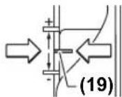
-rgaipahnoI rpaHnHnK (9) nocTaBeTe ro Ha Hajn30 KteNEH; CE cnUsha Kora rgaipapahnoI rpaHnHnK Ke Ce BkNoH.
- Ona6abeTe ja
3aBPkata (15) Ha rpaHmHnKOT 3a dna6oounHa (14), Taka WTO Toj (14) Ke MOKe Cno6oJHo Da ce DnKN.
-ПиNTСHETe ro rpaHnUHnKOT 3aДлбочнHa (14) HaIOny,doEka He IerHe Ha rpaInpaHnOT rpaHnHnK (9).
-Пинсichte ro noctot 3a De6noknaphe (23) Hanaadni NOleka BOte ja nobpunHckata rnodaJa HAOny, Odoeka rnoDAkata (5) He ja donpe nobpwnHata Ha denot wTO ce o6pa6OtyBa. NOBtropHo OTnyWTe Ro nocTOT 3a De6noknaphe (23) 3a da ja qnknpate OBaa No3ujuja.
GOF 1250 LCE: BknyeTe ro dHnHTaHnHOT npKka3a nnabocuHa Ha npeknHyBaOTo 3a BknyuBaBe/ NcknyuBaBe (18).PnTnCHete ro KOnyeto (16)3a noDecyBaHe Ha HynTa TouKaTa Ha rpaHnUHKoT3a nnabocuHa (14).
GOF 1250 CE:ПИЗraуOT co ИнDEкСЧАТа OЗнaka (27) HAmecTeTe ro Ha ПОЗиЦЯ 0Ha cKaIATA 3a ДпавочиHa rILOdaHBe (26).
-Notctabete ro rpaHnHnKOT 3a dna6oynHa (14) Ha cakaHaTa dna6oynHa 3a rIOnahe n 3aTeHne Ta3aBpTKata (15) Ha rpaHnHnKOT 3a dna6oynHa (14).
GOF 1250 CE: BHHMabajte Ha Toa, IN3raqOT CO HnDEKCHATA O3Haka (27) da He rnoMEcTyBaTe NOBeKe.
-ПиNTHcHTe ro nOCTOT 3a De6bNoKpaHBe (23)И BODeTe ja NOBpUHcKcTa rnoDaIa BO HajropHaTnO3uJia.
Pnrolemn dna60unHn Ha rnoDahe Tpe6a da ce HanpaBat NOBeKe npoecn Ha o6pa6oTKa co nomano Baede CtpyrotHH. Co nomow Ha rpaDnnpAHOT rpaHnHnK (9) MoKe Da Ro nOeNtne npocetHa rnoDahe Ha nobEke CTeneHN. Pntoa, noceTe ja cakaHata dna6oHnHa Ha rnoDaHe Co hajn3OK CTeneHn Ha rpaDnnpAHOT rpaHnHnK 3a npBnO tpoec Ha o6pa6oTKa n36epete ro hajBnCOKNT CTeneH. PactoJahneto NomeIy CTeneHnTE MOKe Da CE npOMEHN CO BpTeHe Ha 3aBPTKIne 3a NoDecyBaHe (10).
IIO npobata 3a rnoDaHe, co BpTeHe Ha BpTINBOTO KOnue (25) MoKeTe da ja noDecuTe INaobounHaTa HrNoDaBe ToUHO Ha cKaHnTe DMHeM3HN; CBpTeTe BO npBaue HA CTpeKNHe Ha YacOBnKoT 3a 3rOJeMyBaHe Ha INaobounHa Ta rnoDaHe, a 3a HaMaNyBaHe Ha INaobounHa Ta rnoDaHe CBpTeTe BO npBaue CnpOTNBEN HA CTpeKNHe Ha YacOBnKoT. CkAnata (24) cnYKn 3a opHeNTauJa. ENo BpTeHe OJROBapHa HoONKnHa HoNecyBaBe oD 2,0 mm, edHa oUptnKHe Ha DOnHNOT pa6 Ha CKanata (24) OJROBapHa IpOMeHa HoONKnHATA HoNecyBaBeTo 3a 0,1 mm. MakcmaHATA DonKnHa HoNecyBaBe N3HeCyBa ±8 mm.
PnmeP: nTpe6HaTa dna6OuHa Ha rnoJahe Tpe6a da H3NecyBa 10,0 mm, a npH np6HTo rnoJahe cTe n3MePHe dna6OuHa o9,6 mm.
- Cbptete ja ckanata (24) Ha 0.
-CBPTETo BPTNBOTO KONue (25) 3a0,4mm/4 upTNuKN (pa3nka OJ 3aJaDeHata n peAnHata BpeHocT) BO npaBeu Ha CTpeKNTe Ha YacOBHNKOT. - PnpoBepe ja n36paHata dna60uHa ha rnoahe co yuTe eHNO np6Ho rnoaHe.
GOF 1250 CE: No noctaBybaHbTe Ha dna6oHHata Ha rnoDaBe, He ja MeHyBaJte NOBeKe no3njujata Ha nH3raUOT (27) Ha rpaHnHnKOT 3a dna6oHHa (14) 3a da MOKE BO Cekoe BpeMe Da ja IpoHTate MOMHTanHaTa dna6oHHa HA ckanata (26).
GOF 1250 LCE: Ke ce npkaKe MOMeHaTaIHaTa INa6OuHa Ha IIOdaHe Ha ekpaHOT (21).
Cobetn npn pa6oTebeTo
3aunHTTeTn anatne 3a rnoDahe oD yapn.
Ppaeu npoeec Ha rnoahe (BnDn Cnka F)
Ipoecot Ha rnodahe cekoraw Mopa da ce n3bpyBa cnpoTH npabeuOT ha potaunja Ha rnodankata (5) (cnpoTBeH TeK).PiN rnoDahe BO npabeuC Ha potaunja (nCT TEK) eNEKTPNHNO t anat MOKe Da BN 36era od pakata.
IocTaBeJe cakaHaTe dna6OuHa Ha rnoJaHe (BnDn "NoecyBaHe Ha dna6OuHaTa 3a rnoJaHe", CtpaHnua 184).
EnkprnHnot anat co MOHTnpaHa rnoJaKa nocTaBeTe ro Ha denot 3a o6pa6oTyBaHe n BknyeTe ro.
PnHTCHETe ro nocT0r 3a De6bNOknpaBe (23) Hana3aH BODeTe ja NOBpUHcKaTa rnoJaKdo KpaJ BO npaBeu Ha OCHOBHATA nOoA (13). NOBTOPHO OTnyWtTe Ro nocTOT 3a
Ie6nKpahe (23) 3a da ja qnknpate Obaa InaobounHa Ha BnabHyBahe.
Ipoecot Ha Itoahe Bpwte Ro CO KOHCTaHTHa 6p3nHa.
No 3aBpsiBaHTo Ha npocet Ha ItoaHe, BpaTe ja
noBpwnHckata rnoDaIka BO HajropHa no3nJa.
NcknyeTe ro eNeKTpruHnot anat.
Itoahe co nomouen rpaunnK (Bm cnaKa G)
3a o6pa6otka Ha rolemn denobn Ha np. kaj rnoankn 3a
Kne6oBN, KAKO NMOWEH rpanuHNK Ha denot 3a
6pa6otybahe MoKe Da npuBpcHTe eoHa daacka nn
naJcHa Ha ja BoNte NOBpHHckata rnoanKa no
doJHKHATA Ha NOMOHNOr parnuHNK.BoTe ja
NoBpHHckata rnoanKa Ha HsPamHETata cTpaHa Ha
Hn3raKkata nlova NoDjXHHaTa Ha NOMOHNOr rpanuHNK.
O6nkyBaHe nIpoJaBe Ha pa6oBu
Pn obnyBahe nIpoaHe ha paobBu 6e3 npalehen rpaHnHnK, IIOaNkata Mopa da 6ne opemeHa co YNBnBODNIKN N KyrnnuHO neKnWte.
BoTe ro BknyeHnO tneKtpuH e ana t cpaHnHO Ha
IeNoT wTo ce o6pa6oTyBa,doEka YNBInTe-BODNKn Hn
KyrnnHOTo leKmTe Ha rnoJaKaTa He HanerHe Ha pa6oT od
IeNoT wTo ce o6pa6oTyBa.
BoTe ro eneKtpnHnO nAaT no pa6oHa denot 3a
obpa6oKa. PpntoBa BHmAbajte Ha ToUHnO arO npn
notnpaBeto. PperonemHnO pInTHcOK MoKe da ro OwTeTa
pa6oHa denot wTo ce obpa6oTyBa.
IIOdaBe cO npaPeneH rpaHnHnK (BnHcNnKa H)
BMETHETe ro npaenHHOT rpaHnHK (33) co BOeKInTe npaKn (34) BO OCHOBHATA nOoA (13) nBpCTO 3aTERHTe RO c 3aBPKNTE (7) COODBeTHO HA NOTpe6HNTE DmEH3N.
Co nenepyTKa-3abptknte (36) 1 (35) MoKe DOONOHHTeHIO da ja noedeCte DoJKNHaTa Ha npaJIeHNHOT rpaHNUHK.
CoBpTnBOTOKoNue(37)noOana6aByBaHeHaDbete nenepyTKH-3aBpTKH(35)MOKeΦnHOda ja naNoDECHTe DOJHKHATA.EdHO BpTeHo eOroBapa Ha DoJHKHa HA noDecyBaHBeo2,0mm,eHa oO npTnKHe Ha BpTnBOTO KoNue(37)OroBapHa npOMeHa HoJOKHATA Ha noDecyBaHbeto 0,1 mm.
Co uHaTgpaHnHnK (38) MoKeJa ja npomeHnte eefekTHBhata KOHTaKTHa NOBpuHnHa Ha napaneHnOT rpaHnHnK.
BoTeTo BkIyHHeNt EeKtpHHe anapat co paMHomepHo DnHexe HcPaHHeH PnTHcOK Ha npaJIeHHOT rpaHnHnK No DoJxHnHaTa Ha paB0T od DeNoT WTo ce 6pb6bTyBa.
PnI rnoBaHe co npaaneHepraHHNHK (33) Tpe6a da ce Bpwn BwMykyBaHe Ha npBtA/cTpyrotHInTe CO NOMOHN Cnejuane H aanTep 3a BWMykyBaHe (39).AanTepOT 3a BWMykyBaHe MoKe Da ocTaHe MOHTnpaH.
Itoaankco aantep 3a wectap (onpema)
3a kpyxno rnodahe moke da ro ynotpebte aanterpoT 3a wectap.
TIOdahe co uHa-BoHnka (onpeMa)
Co NOMO W H A WHHHTE BOHNKIN a daaTepoT 3a WHHHTE BOHNKMOKe Da BpWHe TnpaBOHNHCKN DnHexeHa.
TnOdaBe co KOnHpHaTaaypa(BNINcNkN1-L)
Co nomoi Ha konipnHaTa yaypa (43) MoKe da nppeHecyBaTe KOHTpyo OD HaOpTN ODN. 1a6NoHn Ha DeNt 3a o6pa6OtuBaHe.
Cnpede6enHataHa 7a6noHOT Ond. Hauptot Ond6epete ja cooDBethata KOINHPa yaypa.BndejKn BnCSHaTa Ha KONHPa Taaypa Ctpu,wa6noHOT Mopa Da HMa MMHMajHa de6enHaa od 8 mm.
3a da ce Kopnctn konipnHa Ta yaypa (43) HajnpBO mopa da ce BmTe HSDS-aaanTepo Ha konipHa Ta yaypa (40) Bo nIINrAqkata IIOya (11).
IocBaTe ro aanTepo3a konHpHata yaypa (40) od rope Ha nIraKATA IIOOyA (11) H 3aBpTe T co 2 aBPTKn 3a npuBpCTyBaHe (41). BHHMaBaJte Ha Toa, NoCTOT 3a De6NoKpHaBe 3a aAnTepo3a konHpHata yaypa (42) da MoKe cno6oDoHa ce DnKn.
BmHTeToIocT3aDe6nKnpaBe(42)Bo npabeuHa CTpeKaTa HCTaBeTe ja KOnnphata yaypa (43) odDony BO SDS-aanTePOT3a KOnnHa yaypa (40).KoInpahnte 3anu Mopa UBCPTO Da CE BmTHaBO OTbOpHe Ha KOnnphata yaypa (43).
IpoBepTe ro pactoJahneto OJ cpeHnata Ha rnoJaKata na pa60t ha konnpHa taaypa(Bnu, UeHTpnaBe Ha ochoBHata nOua (Bnu cnka N),CTpaHnca 185).
> N36pepe noman djuametap Ha rnoankata od BHATpeHHOT djuametap Ha KOHNPHATA qaypa.
Ppoec Ha rnodahe
BoTeToBknyeHnToEneKtpuueH anat co konnpHata yaypa (43)Ha uabnoHOT.
PnHTCHETe ro noCTOT 3a De6NOKpahe (23) Hana3aH noneKa BOTe je naOBpuHHCKata rnoDAkHaNoIy,doEka He ce NoCTTne NOceHeTa dnaOouHa Ha rnoDaHe. NOBTOPO OTnyTete ro noCTOT 3a De6NOKpahe (23) 3a da ja fKnCpate Obaa Dna6OounHa H BnA6HyBaHe.
BoTe ro eNeKtpnHNoT aIaT co KOnnHpHaTa qaypa WTo cTpu (43) co cTpaHnueh npHTcOK no DoJxHaTa Ha wa6noHot.
LcHtppaHe Ha ochoBHaTnloa (Bmncnka N)
3a da e noeHaKaBO hTo paCtoJaHHeTo od CpeHHaTa Ha rnoanKATA do pabot HA KOnnphata yaypa (43)doKoNky e notpe6HO KOnnphata yaypa nIINrAukata nIOua (11),MOKe da ce CEHTpPaAT eHa KOH npya.
PnHTNCHETe ro nocTc 3a de6nKpahe (23) Hana3adn BODeTe ja nobpHnHcKa rnoDAnkA do KpaJ BO npaBeuHa OCHOBHATA nOoA (13). NOBtOPHOOTnyWTe Ro nocTc 3a de6nKpahe (23) 3a da ja qnknpate OBaa Dna6OunHa Ha Bdna6HyBaHe.
Ola6abete r3aBPTKHTe 3a npuBpcTyBaHe (44) 3a OKony 2 BpTeHa, Taka ITo IIN3raKata IIOva (11) Ke MoKe cno6oDoHa ce DnKn.
IocTaBete ro TpHOT 3a ueHTPnpaHe (45) BO npHpaTOT 3a anat kako wTo e npKakaoHa h cNkata. PauHo 3aucbpcTe
186 | Srpski
ja npetyphata HABpTKa, Taka ITO TPHOT 3a ueHTpnpahe cyeuTE MOKe CNo6oNDHa Ce DnKn.
UeHTnpaJte Hn TpHOT 3a UeHTnpaHBe (45) N KOnnPHaT aaypa (43) eEN Co npYr, co neCHO NmecTyBaHe Ha nIIN3raKATA IIIOVA (11).
POBTOPHO 3aTeHHeTe r3aBPTKHe 3a npuBpcTyBaHe (44)
I3BaTeToTpHOT3aueHTnpaHe(45)o npnpaTOT3a anat.
PnHCTe ro nocTt a de6nKpahe (23) HoTe ja NOBpHHckata rnoaKa BO HajropHa no3nju.
Mehybahe ha 6atepnja (GOF 1250 LCE) (BnH cnka M)
OTbopete ro nokloneoH na nperpaata 3a 6atepn (22) harope Hn3BaTe ja 6atepnjata. CTabete HoBa 6atepnja (TIN CR2032). No3HTHBHnot noHa 6atepnjata Mopa da nokkyba HaHaIpeKOH nokloneoH na nperpaata 3a 6atepn (22).CTabeTe ro dNxtyHrot (46) n 3aTbopete ro nokloneoH na nperpaata 3a 6atepn (22).
OdpKyBaHe n cepBnC
OdpxByBaBe n uHCTeHe
Ppe6nno KaKbHa HHTepBHeuJa Ha eNeKtpHnNot anat, h3Bneye ro ctpyJHnot npKnnyok od shHaTa do3Ha.
OpxybaTe rHnctHe eneKtpnHnot anat HOTBOPHTa npoBepyBaHe, 3a da MoKe do6po H6e36eHno da pa6oHTe.
PnEcktpemHn ycnoBn Ha npmHeHa,doKoKy e BO3MOxHO cekoraW KOpHCTeYpe3a BWMyKyaBahe. UcHCTe Tn NoecTo OTbOpHTe 3a npOBetpyBaBe co edha YETKa n pNknyte 3aWTInTe NpEKHyBa 3a dHepenJnHa cTpyJa (PRCD).PnO6paOtKa Ha METAn,BO BHTpeuHocTa Ha eNEKTPnuHOT anat MoKe Da ce cObepc cnpoBOnBa npab.MoKe da ce oWTeTH 3aWHTnTHa H30aunJa Ha eNEKTPnuHOT anat.
Iokonye notpe6Ho KOpNCTeHe Ha npKnyeH Ka6en, ToraH HababeTe ro od Bosch HnCneuJAn3npaHa npOaBnua 3a Bosch-eneKtpnH anAtn, 3a da n36erHete 3arpo3yBaHe ha 636edHocTa.
CepBncha cnjx6a n COBET npn KOpNCTeBe
CepBnchata cnjx6a Ke OngroBOp Ha BaWnte npaHaBa BO Bpcka co nonpaBkata n OndpyBaHeto Ha BaWnOT npo3BOk KaO Hpe3epBnHTe DeIOBn. O3HaKn 3a EKcNIO3nJa INHΦopMaun 3a pe3epBnHTe DeIOBn HCTo Taka Ke HajTe Ha: www.bosch-pt.com
TMMOT 3a COBetyBaBe npn KopncTeHe Ha Bosch Ke BN NOMORHe DOKOLKY HMaTe npaHaHa 3a HaHIne npOn3BOmN onPema.
3a CNTe npaaHbHa HapaKHa pe3epBn DenOB,Be MOINHe HabeTe ro 10-ncfpeHHOT 6poj Oc cneuNkauNoHATA NIOUka Ha npoN3BOJOT.
CeBepHa MaKeDoHnJa
Д.Д.Енковс
CabaKobayebNK 47H,6poj3
1000 Ckonje
E-nowta: dimce.dimcev@servis-bosch.mk
HHTrepHET: www.servis-bosch.mk
Ten./φακc:02/2467610
Mo6.:070595888
D.I.T.Y "POJKA"
JaHnyKpOBcKn 66;T.LA BTOKOMaHaJIOKaI 69
1000 Ckonje
E-nouta: servisrojka@yahoo.com
Ten: +38923174-303
Mo6: +389 70 388-520, -530
OttpaHyBaBe
EneKtpnHHTe ypei,akymyataopckhte 6aTePH/ 6aTePHTNE,Onpemata H am6anaJHTe Tpe6a da ce otctpaHAT Ha ekolowkn npHpaTINb HauHH.

He nФрпajte eneKtpnHHTe ypei n 6aTePnHTe BO domaHaHaTa KaHTa 3a OTnadou!
Cama 3a 3emjnte oEY:
CnopeE EBponckata perynatna 2012/19/EU enektpnHte ypei nTO CE BOH ynotpe6a ndepekTHnte nnncopnchtne 6atepn Cnope nperynatbata 2006/66/EC mopa oDienho da ce co6epa n da ce peuknpaat 3a noBtphy ynotpe6a.
Srpski
-Pakopine atrama (9)
(5jglll 100 baw ggo (39)
SDS aIgai guii dAa (40)
2x) aLgall aal gw
aLqJgWJ aLgAeJUJgJgJgJgJ (42)
ω(43)
gJgU UU UU UU UU (44) (5x)
jSjaiJlawo (45)
μjw jil (46)
ggaal gglgllsuiicjSjjglljbljaaA
UuJg aolglgul gagmuog 1g
4e jgll ajjll
Lgao g q
aao 1 aaii i jui
jg g qwwx .uug uui
UuUgaa gaiiJl
aJbUJI jJd
JUJIg gJg JKw agJU
uuii uo daaoo ie duoi jaiuuiu
yolwI yjoo Jg jai g
aJUJJJg
.1g≤s≤aui pai 2g aoi jll
g j aai g, uuiuill saoaoo
.ajwJgawJgjoo
.1LJI JJdJI
sic aJbll joojwaioll ggiil lww
JUg jgjgl JlJd uoldo
Lg
D LCE(
1g aaiJl 0g
jlo|1sloj|g
. laIg

Ubi31 Ulsj
g juulg Jlu
JgAuljUo gss
gJyUg/9 gJg
.
JUgJjJgJgJgJgJgJgJg
Jusu
yaaoll Jlosw21
gglg jgjll jajd auiuSll oess s
aJgblgagllg aJlJI JLSaJg
g wI jJjU J slgog jslg
. ul jull
Jai sic aydyd jn jydo yao
.aauio jp pai saiwlg UaU
oJgaaJI-Ij2JI
oJgWJ JgJgJgJgJgJgJgJgJgJgJgJgJgJgJgJgJgJgJgJgJgJgJgJgJgJgJgJgJgJgJgJgJgJgJgJgJgJgJgJgJgJgJgJgJg
aabbsllgoggl aagggl ayjL
(1)
lab2lg Juaaui 1uoo ujj (2)
)aJgJl aolJIGF 1250 LCE(
gogjgougoggolo (4)
(5)
jIgJgoo CwEglj6
)glll aull llaal g1270
0 j (8)
(9)
aaiiI uui
GOF 1250 CEGOF 1250 LCE
aagle jjoo diSlo
3601F260..3601F261..
aioll
1250 1250
aawJJJ
233
| GOF 1250 CEGOF 1250 LCE | ägloge jürgen älslo | ||
| 10000-24000100001240000 | sdd lalldalldal | ||
| ● | ● | lāmaa maaa | |
| ● | ● | jürgen lalldalldal | |
| ● | ● | jürgen lalldalldal | |
| ● | ● | jürgen lalldalldal | |
| ● | - | jürgen lalldalldal | |
| ● | - | jürgen lalldalldal | |
| 8-6 | 8-6 | pø | aaggio aagob ápj |
| ¼ | ¼ | pøjø | jøjø |
| pø6060 | jøjø | ||
| pø≤3,63,7 | jøjø | ||
| /Ⅱ | |||
algJk aollll jlllgl glll lgl 230 gl [U] wai d> Jc uill
jLJ/1JbJ
jJlI pJUwIg
uiaiaiaiaiaiaiaiaiaiaiaiaiaiaiaiaiaiaiaiaiaiaiaiaiaiaiaiaiaiaiaiaiaiaiaiaiaiaiaiaiaiaiaiaiaiaiaiaiaiaiaiaiaiaiaiaiaiaiaiaiaiaiaiaiaiaiaiaiaiaiaiaiaiaiaiaiaiaiaiaiaiaiaiaiaiaiaiaiaiaiaiaiaiaiaiaiaiaiaia iaaii aaii aaii aaii aaii aaii aaii aaii aaii aaii aaii aaii aaii aaii aaii aaii aaii aaii aaii aaii aaii aaii aaii aaii aaii aaii aaii aaii aaii aaii aaii aaii aaii aaii aalaaa IaagaaeaaaagaaeaaaagaaeaaaagaaeaaaagaaeaaaagaaeaaaagaaeaaaagaaeaaaagaaeaaaagaaeaaaagaaeaaaagaaeaaaagaaeaaaagaaeaaaagaaeaaaagaaeaaaagaaeaaaagaaeaaaagaaeaaaagaaeaaaagaaeaaaagaaeaaaagaaeaaaagaaeaaaagaaeaaaagaaeaaaagaaeaaaagaaeaaaagaaeaaaagaaeaaaagaaeaaaagaaeaaaagaaeaaaagaaeaaaagaaeaaaagaaeaaaagaaeaaaagaaeaaaagaaeaaaagaaeaaaagaaeaaaagaaeaaaagaaeaaaagaaeaaaagaaeaaaagaaeAAAAGAAAGAAAGAAAGAAAGAAAGAAAGAAAGAAAGAAAGAAAGAAAGAAAGAAAGAAAGAAAGAAAGAAAGAAAGAAAGAAAGAAAGAAAGAAAGAAAGAAAGAAAGAAAGAAAGAAAGAAAGAAAGAAAGAAAGAAAGAAAGAAAGAAAGAAAGAAAGAAAGAAAGAAAGAAAGAAAGAAAGAAAGAAAGAAAGAAAGAAAGAAA AGAAA AGAAA AGAAA AGAAA AGAAA AGAAA AGAAA AGAAA AGAAA AGAAA AGAAA AGAAA AGAAA AGAAA AGAAA AGAAA AGAAA AGAAA AGAAA AGAAA AGAAA AGAAA AGAAA AGAAA AGAAA AGAAA AGAAA AGAAA AGAAA AGAAA AGAAA AGAAA AGAAA AGAAA AGAAA AGAAA AGAAA AGAAA AGAAA AGAAA AGAAA AGAAA AGAAA AGAAA AGAAA AGAAA AGAAA AGAAA AGAAA AGAAA
gjcklK
JgJSSUwUwUgjSsUuUaI Lao, Jaa 0 uuaillg Jaa Ugs Jaull sia. daaio lac oJd
a d 1d
jIgJl pjc yIgjS! aIa oJy JI jI. Jaal aaLo eo Jo sJug Jauill sic
Jlll Jn Jn Jn Jn Jn Jn Jn Jn Jn Jn Jn Jn Jn Jn Jn Jn Jn Jn Jn Jn Jn Jn Jn Jn Jn Jn Jn Jn Jn Jn Jn Jn Jn Jn Jn Jn Jn Jn Jn
(19) 20202020202020202020202020202020202020202020202020202020202020202020202020202020202020202020202020202
15(9) 1
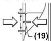
(14) (14)
pui jS. auiuqS1 0eai gao
a0s jaoJI aJgSJI sSJI u
230 uua 220.1
山
GOF 1250 LCE:asu
aagai aalil ojaoo aan ydiuSII)3( .Jawll aobgabw oLx
UJUJIU UJU JUJUJIU JUJI
)GOF 1250 LCE 6j9
Jauu aJaua Jaua Jaua Jaua Jaua Jaua Jaua Jaua Jaua Jaua Jaua Jaua Jaua Jaua Jaua Jaua Jaua Jaua Jaua Jaua Jaua Jaua Jaua Jaua Jaua Jaua Jaua Jaua Jaua Jaua Jaua Jaua Jaua Jaua JAUA JAUA JAUA JAUA JAUA JAUA JAUA JAUA JAUA JAUA JAUA JAUA JAUA JAUA JAUA JAUA JAUA JAUA JAUA JAUA JAUA JAUA JAUA JAUA JAUA JAUA JAUA JAUA JAUA JAUA JAUA JAUA JAUA JAUA
LauuogjgJdSs
28(oo)uJgSsScbaaabwglcs
2-1
Iwgiu Uai Jsc 4-3
6-5
g jgj gjj
JUJIJI JIJIJIJIJIJIJIJIJIJIJIJIJIJIJIJIJIJIJIJIJIJIJIJIJIJIJIJIJIJIJIJIJIJIJIJIJIJIJIJIJIJIJIJIJIJIJIJIJIJIJIJIJIJIJIJIJIJIJIJIJIJIJIJIJIJIJIJIJIJIJIJIJIJIJIJIJIJIJIJIJIJIJIJIJIJIJIJIJIJIJIJIJIJIJIJIJIJIJIJIJIJ
| öjüng bäusst | jüldal [po] | ülsal dals |
| 6-5 | -40 | ülsal dals |
| 4-3 | 12-20 | (ülsal) |
| 2-1 | 22-40 | |
| 6-5 | -40 | ülsal dals |
| 6-3 | 12-20 | (ülsal) |
| 3-1 | 22-40 | |
| 6-3 | -40 | ülsal dals |
| 4-2 | 12-20 | ülsal dals |
| 3-1 | 22-40 | |
| 3-2 | -45 | ülsal dals |
| 2-1 | 16-40 | |
| 2-1 | -45 | ülsal dals |
| 1 | 16-40 |
yao 3 000
LbXg
(goc b,jbl)joll goc b 234(aaJl,“jol
aio 1c bai aui jySll oai Jn Jn Jn Jn Jn Jn Jn Jn Jn Jn Jn Jn Jn Jn Jn Jn Jn Jn Jn Jn Jn Jn Jn Jn Jn Jn Jn Jn Jn Jn Jn Jn Jn Jn Jn Jn Jn Jn Jn Jn Jn Jn Jn Jn Jn Jn Jn Jn Jn Jn J
(29)bgsoll labg juiu liao c wj 2uui juc b
山 10000000000000000000000000000000000000000000000000000000000000
(29)labg juiu liao le bai (2) ciuii .aui
()jg 10
JUeSJI JJJ (oJI)
山
gac lao, jol) gajol jolgac lao
(234ddo,“jdo
aJd jai aao go auiu ooi
aJgWgIgJgJgJgJgJgJgJgJgJgJgJgJgJgJgJgJgJgJgJgJgJgJgJgJgJgJgJgJgJgJgJgJgJgJgJgJgJgJgJgJgJgJgJgJgJgJgJgJgJgJg
a1yJ≤J1
Jg,clJI (23) JIJIJIJIJIJIJIJIJIJIJIJIJIJIJIJIJIJIJIJIJIJIJIJIJIJIJIJIJIJIJIJIJIJIJIJIJIJIJIJIJIJIJIJIJIJIJIJIJIJIJIJIJIJIJIJIJIJIJIJIJIJIJIJIJIJIJIJIJIJIJIJIJIJIJIJIJIJIJIJIJIJIJIJIJIJIJIJIJIJIJIJIJIJIJIJIJIJIJIJIJIJ
a aolai g aigll jagljj ailo
(23) [a]jJz. (13) aJIJI
ploal gai pabiio g9 sy jjall aolac sai
jSjJgajaggljjjajllaaSlo aagd
. jolal lacac- qj1 sss lcai
aJUgSJI oJg[ab]
(Gjgll jil) seluogjjill
jssll aobaiuuiiaablcglgul jso
0uSJI JgBg 8aJLoo SiC scluo aay
agll jjai slo jwog dio gjgl j9 sic
juiil aislo j. sluoi JauoJluoLc
aJy jjI gJgJgJgJgJg
.
jIg jJ
gglgul gglkwl glgll jg sic
jaggljg jaojjaaaag
.
Jai aai gai lgluiu aui jgll oai a
Joo gI JJJ Jgll Joo li jilai joo
JuswI daabag agla go jjall aanu yolul ujs
laIooogjai
aag a glu Jusol sio1 gcl aygSll oessd ag
gaiy 1kui jui i ci uui duii.
jI! jll bai all yag aigbail aggl
Jswll aabg aela
(Hjgall jbl) (jglill ggo jolll
(34) aJJI jJauaJIg (33) (sjlgill
olaiuabjpsg (13) occll aao 9
glll wlaal 7) gU
ssaaabai bai (16)jjllb
146201
dcl abwgljllgol:GOF 1250 CE
gac wu0 ggl 27)
)26
jooil (14) 000
(15)UgUUBjSgUgU
1462
GOF 1250 CE
27(jolldo)clabwglg2jollllo
aiSlo 2g (23) jgj
ggljaggljjjaii
aJusuulusjolal jlcil jjoll glacg
aLac 15 g oJuiuI Jg I Goo
aLac auaaj (9) Ljul 10aiwU jSos
gac bao paiuU. jyj jyj
a aal a jol ggejll
J 1
UgljIJUJnOuJLJI JnJgUwJU
)10(
aii j 1111111111111111111
gaglll jai jj (25) jlgll
aJl aclwll joc aK 0j0
Jac aSpaol Jusc g jj jai (gac
24(10)
aIoo oJg Js Jlaai.aaalil aagj
aJUy ju 2,0 2
a9luu 1jui jilai (24) wuaa aagll
gaoJI buiJ aIwO gUg .0,1 JsaJ buiJ
8±
gSj jy yjai jiai gac:Jt
jz jgoc Jd ajjll jdlal alac 10,0
9,60jdo
.0UJ(24)uLdJ
4/0,4J(25)gJgl
aagg jjraa aagaa jjj
.aaulljlaac aolal (a)
jáulac Ula joo sall jolll gac 1
.(5)a
jusu pa juaI gac bao:GOF 1250 CE
LJ.14) 11111111111111111111111111
jai jiai iag aolai elis
26(100)
j j01GGE:1250LGE:
214joll 0
JdI dI
.ooalglg jol jjall aLoay
F(0jgJJI jal) jal alocg jalol
olil usc loils jall aLac pU
()()(5)jallaaaljlg
.1s40 (44) Cuiuil Uglj bpa
45(ahgluiebaj
山g(23)UJxj
Sahba Technology Group
jtoal jbo gjw
1
:d+964(0)790193C
+971(0)4422189
aJgJL aSRoots Arabia
JU LLOJU JELJ
jlaoc11623jJJI.
:110068
:+96264398990
:gjgJXl JyJibosch@rootsjordan
#
Robert Bosch Morocco SARL
joo oolg.53
LJ120300
+212529314327:JJI
sav.outillage@ma.bosch.com: ≤
lac
p.p. w gllg jililo
baa,15gj,131sμgssio
jlaacablW.112:5yUuUgSJI
.iiS iiS Cwui CwU J Soo
.iiS Jg j 1 g jj j j j j j j
waiuiIj0y.
JJJjjj jSoo
jglgwsjg jgsd gds
J 1j1 j
Jg g Ugsa
Ij IqiaimJg gia! Jgsw daom
.

jLwUw
cuii jSoo iJgws
caljLwuggagw,
gug uu 15
laimj ajiagglg lglg slyga
.
olswjolalawl jIgo
(59)poojgduuus
gSswyJgO,ogjJgJgJgJdda
Jw yu juaa g Ssw Jlaaalw a
gLg gjg jSjg jGwjjLiS jgj
(SjLg)SjIwagaiogaijiggglqalgw
.uwuwo
Ug ju 159jglj
jLJUwli0 jg g u
lkwJjAl
o oio jgi j s ol b i s j 1s ojai
gai d s wiy go yj j1y d logjo
.0d a j
(1)
/ aos2
jgi jUJ(DF1250LCE)
(0j1gj0jL0jgo)GgSg0jgo (4)
A SJSJ5
242|w