GRL 150 HV Set 2 - Laser level BOSCH - Free user manual and instructions
Find the device manual for free GRL 150 HV Set 2 BOSCH in PDF.
Download the instructions for your Laser level in PDF format for free! Find your manual GRL 150 HV Set 2 - BOSCH and take your electronic device back in hand. On this page are published all the documents necessary for the use of your device. GRL 150 HV Set 2 by BOSCH.
USER MANUAL GRL 150 HV Set 2 BOSCH
OBJ_BUCH-757-004.book Page 2 Wednesday, December 10, 2008 4:25 PM3 | 1 609 929 R48 | (10.12.08) Bosch Power Tools
OBJ_BUCH-757-004.book Page 3 Wednesday, December 10, 2008 4:25 PM1 609 929 R48 | (10.12.08) Bosch Power Tools 4 | LR 1Professional
inch LR 1 Professional
OBJ_BUCH-757-004.book Page 4 Wednesday, December 10, 2008 4:25 PM5 | 1 609 929 R48 | (10.12.08) Bosch Power Tools LR 1 Professional 45 mm
OBJ_BUCH-757-004.book Page 6 Wednesday, December 10, 2008 4:25 PM| 7 Bosch Power Tools 1 609 929 R48 | (10.12.08)
OBJ_BUCH-757-004.book Page 7 Wednesday, December 10, 2008 4:25 PM8 | Deutsch 1 609 929 R48 | (10.12.08) Bosch Power Tools
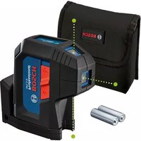
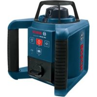
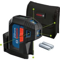
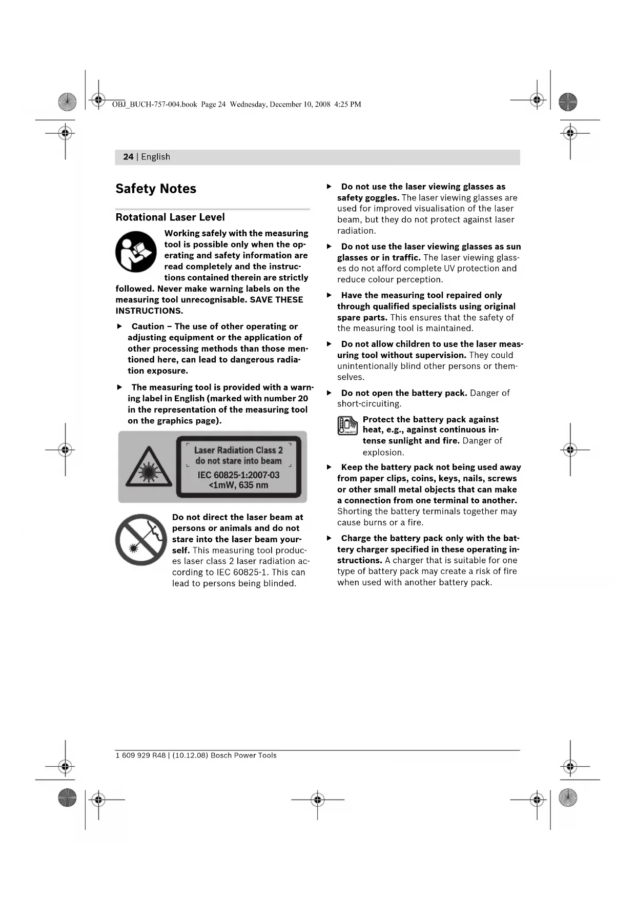
Safety Notes Rotational Laser Level Working safely with the measuring tool is possible only when the op- erating and safety information are read completely and the instruc- tions contained therein are strictly followed. Never make warning labels on the measuring tool unrecognisable. SAVE THESE INSTRUCTIONS. f Caution – The use of other operating or adjusting equipment or the application of other processing methods than those men- tioned here, can lead to dangerous radia- tion exposure. f The measuring tool is provided with a warn- ing label in English (marked with number 20 in the representation of the measuring tool on the graphics page). Do not direct the laser beam at persons or animals and do not stare into the laser beam your- self. This measuring tool produc- es laser class 2 laser radiation ac- cording to IEC 60825-1. This can lead to persons being blinded. f Do not use the laser viewing glasses as safety goggles. The laser viewing glasses are used for improved visualisation of the laser beam, but they do not protect against laser radiation. f Do not use the laser viewing glasses as sun glasses or in traffic. The laser viewing glass- es do not afford complete UV protection and reduce colour perception. f Have the measuring tool repaired only through qualified specialists using original spare parts. This ensures that the safety of the measuring tool is maintained. f Do not allow children to use the laser meas- uring tool without supervision. They could unintentionally blind other persons or them- selves. f Do not open the battery pack. Danger of short-circuiting. Protect the battery pack against heat, e.g., against continuous in- tense sunlight and fire. Danger of explosion. f Keep the battery pack not being used away from paper clips, coins, keys, nails, screws or other small metal objects that can make a connection from one terminal to another. Shorting the battery terminals together may cause burns or a fire. f Charge the battery pack only with the bat- tery charger specified in these operating in- structions. A charger that is suitable for one type of battery pack may create a risk of fire when used with another battery pack.
<1mW, 635 nm OBJ_BUCH-757-004.book Page 24 Wednesday, December 10, 2008 4:25 PMEnglish | 25 Bosch Power Tools 1 609 929 R48 | (10.12.08) Battery Charger Read all safety warnings and all instructions. Failure to follow the warnings and instructions may re- sult in electric shock, fire and/or serious injury. Keep the battery charger away from rain or moisture. Penetration of water in the battery charger increases the risk of an electric shock. f Do not charge other batteries with the bat- tery charger. The battery charger is only suit- able for charging the Bosch battery/battery pack inserted in the rotational laser level. Danger of fire and explosion when charging other batteries/battery packs. f Keep the battery charger clean. Contamina- tion can lead to danger of an electric shock. f Before each use, check the battery charger, cable and plug. If damage is detected, do not use the battery charger. Never open the battery charger yourself. Have repairs per- formed only by a qualified technician and only using original spare parts. Damaged battery chargers, cables and plugs increase the risk of an electric shock. f Do not operate the battery charger on easi- ly inflammable surfaces (e.g., paper, tex- tiles, etc.) or surroundings. The heating of the battery charger during the charging proc- ess can pose a fire hazard. f Under abusive conditions, liquid may be ejected from the battery; avoid contact. If contact accidentally occurs, flush with water. If liquid contacts eyes, additionally seek medical help. Liquid ejected from the battery may cause irritations or burns. Laser Receiver Working optimally with the meas- uring tool is possible only when the operating manual and working instructions are read completely, and the instructions contained therein are strictly followed. SAVE THESE INSTRUCTIONS. Keep the measuring tool away from cardiac pacemakers. The magnet plate 29 generates a field that can impair the function of cardiac pacemakers. f Keep the measuring tool away from magnet- ic data medium and magnetically-sensitive equipment. The effect of the magnet plate 29 can lead to irreversible data loss. Functional Description While reading the operating instructions, unfold the graphics page with the illustration of the rotational laser level, battery charger and laser receiver, and leave it open. Intended Use Rotational Laser Level The measuring tool is intended for determining and checking precise horizontal partitions, verti- cal lines, building lines and plumb points. Battery Charger Use the battery charger only when you fully under- stand and can perform all functions without limi- tation, or have received appropriate instructions. Laser Receiver The measuring tool is intended for quick finding of rotating laser beams. OBJ_BUCH-757-004.book Page 25 Wednesday, December 10, 2008 4:25 PM26 | English 1 609 929 R48 | (10.12.08) Bosch Power Tools Product Features The numbering of the product features refers to the illustration of the rotational laser level, bat- tery charger and laser receiver on the graphics page. Rotational laser level/Battery charger 1 Shock-warning indicator 2 Shock-warning button 3 Automatic levelling indicator 4 On/Off button of the rotational laser level 5 Button for rotational operation and selection of the rotation speed 6 Variable laser beam 7 Reception lens for remote control 8 Exit opening for laser beam 9 Plumb beam 10 Rotation head 11 Button for line operation and line length selection 12 Charge-control indicator 13 Battery pack* 14 Battery compartment 15 Locking knob of the battery compartment 16 Locking knob of the battery pack* 17 Socket for charge plug* 18 Tripod mount 5/8" 19 Serial number of the rotational laser level 20 Laser warning label 21 Battery charger* 22 Mains plug of the battery charger* 23 Charge connector* Laser receiver* 24 Latch of battery lid 25 Laser receiver spirit level 26 On/Off button of laser receiver 27 Button for adjustment of the measuring accuracy 28 Audio signal button 29 Magnet plate 30 Centre mark 31 Reception area for the laser beam 32 Display 33 Retainer openings for holder 34 Battery lid 35 Serial number of laser receiver 36 Locking screw for holding device 37 Holder upper edge 39 Fastening screw of holder 40 Holder 41 Spirit level holder Indicator elements of laser receiver a “Medium” adjustment indicator b Battery indication c Direction indicator, up d Audio signal indicator e Centre indicator f “Fine” adjustment indicator g Direction indicator, down Accessories/Spare parts 38 Construction laser measuring rod* 42 Laser viewing glasses* 43 Wall holder* (available as of mid 2009) 44 Measurement plate with stand* 45 Ceiling measurement plate* 46 Remote control* (available as of mid 2009) 47 Case 48 Tripod* *Accessories shown or described are not part of the standard delivery scope of the product. A complete overview of accessories can be found in our acces- sories program. OBJ_BUCH-757-004.book Page 26 Wednesday, December 10, 2008 4:25 PMEnglish | 27 Bosch Power Tools 1 609 929 R48 | (10.12.08) Technical Data Rotational Laser Level GRL 150 HV Professional Article number 3 601 K15 300 Working range (radius)
– without laser receiver, approx. – with laser receiver, approx. 30 m 150 m Levelling Accuracy
<± 0.1 mm/m Self-levelling range, typically ±8% (±5°) Levelling duration, typically 15 s Rotational speed 150/300/600 min
Laser type 635 nm, <1 mW Laser beam Ø at the exit opening, approx.
5mm Tripod mount (horizontal) 5/8" Batteries (NiMH) Batteries (alkali-manganese) 2x1.2VKR20 (D) (9Ah) 2 x 1.5 V LR20 (D) Operating life time, approx. – Batteries (NiMH) – Batteries (alkali-manganese) 40 h 60 h Weight according to EPTA-Procedure 01/2003
Degree of protection IP 54 (dust and splash water protected)
2) alongside the axes
Please observe the article number on the type plate of your rotational laser level. The trade names of individual rotational laser levels may vary. For clear identification of your rotational laser level, see the serial number 19 on the type plate. OBJ_BUCH-757-004.book Page 27 Wednesday, December 10, 2008 4:25 PM28 | English 1 609 929 R48 | (10.12.08) Bosch Power Tools Laser Receiver LR 1 Professional Article number 3 601 K15 400 Working range
– with rotational laser level GRL 150 HV 150 m Receiving angle 120° Receivable rotation speed >200 min
– “Fine” adjustment – “Medium” adjustment ± 1mm ± 3mm Operating temperature – 10 °C ... +50 °C Storage temperature – 20 °C ... +70 °C Battery 1x9V 6LR61 Operating life time, approx. 50 h Weight according to EPTA-Procedure 01/2003
Degree of protection IP 54 (dust and splash water protected)
1) The working range can be decreased by unfavourable environmental conditions (e.g. direct sun irradiation).
2) depends on clearance between laser receiver and rotational laser level
Please observe the article number on the type plate of your laser receiver. The trade names of individual laser receivers may vary. For clear identification of your laser receiver, see the serial number 35 on the type plate. Battery Charger Article number 1 609 203 X11 Rated voltage V~ 100–240 Frequency Hz 50/60 Output voltage V= 7.5 Charging current A1.0 Allowable charging temperature range °C 0–45 Charging time h14 Number of battery cells
Rated voltage (Rechargeable batteries) V= 2 x 1.2 Weight according to EPTA-Procedure 01/2003 kg 0.2 Protection class /II OBJ_BUCH-757-004.book Page 28 Wednesday, December 10, 2008 4:25 PMEnglish | 29 Bosch Power Tools 1 609 929 R48 | (10.12.08) Noise Information Rotational Laser Level Measured values determined according to EN 60745. Typically the A-weighted sound pressure level of the measuring tool is less than 70 dB(A). Laser Receiver The A-weighted sound pressure level of the audio signal at one meter distance is 95 dB(A). Do not hold the measuring tool close to your ear! Declaration of Conformity Rotational laser level/Battery charger: We de- clare under our sole responsibility that the prod- uct described under “Technical Data” is in con- formity with the following standards or standard- ization documents: EN 61010-1, EN 60825-1 (measurement tool) respectively EN 60950-1 (battery charger) according to the provisions of the directives 2006/95/EC, 2004/108/EC, 98/37/EC (until 28 Dec 2009), 2006/42/EC (from 29 Dec 2009). Technical file at: Robert Bosch GmbH, PT/ESC, D-70745 Leinfelden-Echterdingen
Robert Bosch GmbH, Power Tools Division D-70745 Leinfelden-Echterdingen Leinfelden, 31.10.2008 Assembly Power Supply of the Rotational Laser Level Operation with Batteries/Rechargeable Batteries Use only alkali-manganese or rechargeable batteries. To open the battery compartment 14, turn the locking knob 15 to position and pull out the battery compartment. When inserting batteries, pay attention to the correct polarity according to the representation on the inside of the battery compartment. Always replace all batteries at the same time. Only use batteries from one brand and with the identical capacity. Shut the battery compartment 14 and turn the locking knob 15 to the position. In case the batteries have been inserted incor- rectly, the measuring tool cannot be switched on. Insert the batteries with correct polarity. f Remove the batteries from the measuring tool when not using it for extended periods. When storing for extended periods, the bat- teries can corrode and discharge themselves. Operation with Battery Pack Charge the battery pack 13 before using for the first time. The battery pack can only be charged with the battery charger 21 intended for it. f Observe the mains voltage! The voltage of the power supply must correspond with the data given on the nameplate of the battery charger. Battery chargers marked with 230 V can also be operated with 220 V. Insert the appropriate mains plug 22 for your mains supply into the battery charger 21 and allow it to engage. Insert the charge plug 23 of the battery charger into the socket connector 17 of the battery pack. Connect the battery charger to the mains supply. Charging the empty battery pack takes approx. 14 h. The battery charger and the bat- tery pack are protected against overcharging. A battery that is new or has not been used for a longer period does not develop its full capacity until after approx. 5 charging/discharging cycles. Dr. Egbert Schneider Senior Vice President Engineering Dr. Eckerhard Strötgen Head of Product Certification OBJ_BUCH-757-004.book Page 29 Wednesday, December 10, 2008 4:25 PM30 | English 1 609 929 R48 | (10.12.08) Bosch Power Tools Do not charge the battery pack 13 each time after using, otherwise its capacity will be re- duced. Charge the battery pack only when the charge-control indicator 12 flashes or lights up continuously. A considerably reduced operating period after charging indicates that the battery pack is used up and must be replaced. If the battery pack is empty, the measuring tool can also be operated off of the battery charger 21 when connected to a power supply. Switch the measuring tool off, charge the battery pack for approx. 10 min and then switch the measuring tool on again with the battery charger connected. To change the battery pack 13, turn the locking knob 16 to position and pull out the battery pack 13. Insert a new battery pack and turn the locking knob 16 to the position. f Remove the battery pack from the measur- ing tool when not using it for longer peri- ods. When storing for longer periods, the rechargeable batteries can corrode and dis- charge themselves. Charge-control Indicator When the charge-control indicator 12 flashes red for the first time, the measuring tool can still be operated for approx. 2 h. When the charge-control indicator 12 lights up red continuously, measurements are no longer possible. The measuring tool switches off auto- matically after 1 minute. Power Supply of the Laser Receiver Use only alkali-manganese batteries. Press the latch 24 of the battery lid outward and open the battery lid 34. When inserting the battery, pay attention to the correct polarity according to the representation on the inside of the battery compartment. When the battery indication b appears for the first time on the display 32, the laser receiver can still be operated for approx. 3 h. f Remove the battery from the laser receiver when not using it for longer periods. When storing for longer periods, the battery can corrode and discharge itself. Operation Starting Operation of the Rotational Laser Level f Avoid heavy impact to or falling down of the measuring tool. After severe exterior effects to the measuring tool, it is recommended to carry out an accuracy check (see “Levelling Accuracy of the Rotational Laser Level”, page 33) each time before continuing to work. f Do not subject the measuring tool to extreme temperatures or variations in temperature. As an example, do not leave it in vehicles for longer periods. In case of large variations in temperature, allow the measuring tool to ad- just to the ambient temperature before putting it into operation. In case of extreme tempera- tures or variations in temperature, the accura- cy of the measuring tool can be impaired. Setting Up the Measuring Tool Position the measuring tool on a firm surface in the horizontal or vertical position, mount it to a tripod 48 or to the wall mount 43. Due to the high levelling accuracy, the measur- ing tool reacts sensitively to ground vibrations and position changes. Therefore, pay attention that the position of the measuring tool is stable in order to avoid operational interruptions due to re-levelling. Switching On and Off f Do not direct the laser beam at persons or animals (especially not at their eye level), and do not stare into the laser beam your- self (not even from a distance). Immediately after switching on, the measuring tool sends out the vertical plumb beam 9 and the varia- ble laser beam 6. For switching on the measuring tool, press the On/Off button 4. The indicators 1, 3 and 12 light up briefly. The measuring tool immediately Horizontal position Vertical position OBJ_BUCH-757-004.book Page 30 Wednesday, December 10, 2008 4:25 PMEnglish | 31 Bosch Power Tools 1 609 929 R48 | (10.12.08) starts the automatic levelling. During the level- ling, the levelling indicator 3 lights up green and the laser flashes in point operation. The measuring tool is levelled in as soon as level- ling indicator 3 lights up green continuously and the laser beam is steady. After the levelling is completed, the measuring tool automatically starts in rotational operation. With the operating mode buttons 5 and 11, the operating modes can already be specified during levelling in (see “Operating Modes of the Rota- tional Laser Level”, page 31). In this case, the measuring tool starts in the set operating mode upon completion of levelling in. To switch off the measuring tool, press the On/Off button 4 again. To save the batteries, the measuring tool is auto- matically switched off when not within the self- levelling range for more than 2 h or when the shock warning is actuated for more than 2 h (see “Automatic Levelling of the Rotational Laser Level”, page 33). Reposition the measuring tool and switch it on again. Operating Modes of the Rotational Laser Level Overview All three operating modes are possible with the measuring tool in horizontal and vertical position. Rotational Operation Rotational operation is especial- ly recommended when using the laser receiver. You can select be- tween different rotational speeds. Line Operation In this operation mode, the vari- able laser beam moves within a limited aperture angle. This in- creases the visibility of the laser beam in comparison to rotation- al operation. You can select be- tween different aperture angles. Point Operation This operation mode enables the best visibility of the variable laser beam. As an example, it is used for easy projecting of heights or checking building lines. Rotational Operation (150/300/600 min
Each time after switching on, the measuring tool is in rotational operation mode with average ro- tational speed. To switch from line operation to rotational oper- ation, press the rotational operation button 5. Rotational operation starts with average rota- tional speed. To change the rotational speed, press the rota- tional operation button 5 again until the re- quested speed is reached. When working with the laser receiver, the high- est rotational speed should be set. When work- ing without laser receiver, reduce the rotational speed for improved visibility of the laser beam and use the laser viewing glasses 42. Line Operation, Point Operation (10°/25°/35°, 0°) To switch to line or point operation, press the line operation button 11. The measuring tool switches to line operation with the smallest aperture angle. To change the aperture angle, press the line operation button 11. The aperture angle is in- creased in two steps; at the same time, the rotational speed is increased with each step. When pressing the line operation button 11 a third time, the measuring tool switches to point operation after brief post-pulsation. Pressing button 11 again takes you back to line operation with the smallest aperture angle. Note: Due to inertia, it is possible for the laser to slightly move beyond the end point of the laser line. To position the laser line or the laser point with- in the rotational plane, manually turn the rota- tion head 10 to the requested position or use the remote control 46. Turning the Rotational Plane when in the Vertical Position When the measuring tool is in the vertical posi- tion, it is possible to rotate the laser point, laser line or rotational plane around the vertical axis with help of the remote control 46. For this, ob- serve the operating instructions of the remote control. OBJ_BUCH-757-004.book Page 31 Wednesday, December 10, 2008 4:25 PM32 | English 1 609 929 R48 | (10.12.08) Bosch Power Tools Starting Operation of the Laser Receiver f Protect the laser receiver against moisture. f Do not subject the laser receiver to extreme temperatures or variations in temperature. As an example, do not leave it in vehicles for longer periods. In case of large variations in temperature, allow the laser receiver to adjust to the ambient temperature before putting it into operation. In case of extreme tempera- tures or variations in temperature, the accura- cy of the laser receiver can be impaired. Position the laser receiver at least 50 cm away from the rotational laser level. Position the laser receiver in such a manner that the laser beam can reach the reception area 31. Set the highest rotational speed on the rotational laser level. Switching On and Off f A loud audio signal sounds when switching on the measuring tool. Therefore, keep the laser receiver away from your ear or other persons when switching on. The loud audio signal can cause hearing defects. To switch on the laser receiver, press the On/ Off button 26. Two audio signals sound and all display indicators light up briefly. To switch off the laser receiver, press the On/Off button 26 again. When no button is pressed on the laser receiver for approx. 10 minutes and when no laser beam reaches the reception area 31 for 10 minutes, the laser receiver automatically switches off in order to save the battery. The switching off is indicated by an audio signal. Selecting the Setting of the Centre Indicator With button 27, you can specify with which ac- curacy the position of the laser beam is indicat- ed as central on the reception area: – “Fine” adjustment, (indication f on the dis- play), – “Medium” adjustment, (indication a on the display). An audio signal sounds when the accuracy set- ting is changed. Whenever switching on the laser receiver, the accuracy level “medium” is set. Direction Indicators The bottom g, centre e and top c indicators (both on the front and rear side of the laser re- ceiver) indicate the position of the rotating laser beam in the reception area 31. Additionally, the position can be indicated with an audio signal (see “Audio Signal for Indication of the Laser Beam”, page 32). Laser receiver too low: When the laser beam runs through the top half of the reception area 31, the bottom direction indicator g appears on the display. When the audio signal is switched on, a slow- beat signal sounds. Move the laser receiver upward in the direction of the arrow. When approaching the centre mark 30, only the tip of the direction indicator g is indicated. Laser receiver too high: When the laser beam runs through the bottom half of the reception area 31, the top direction indicator c appears on the display. When the audio signal is switched on, a fast- beat signal sounds. Move the laser receiver downward in the direc- tion of the arrow. When approaching the centre mark 30, only the tip of the direction indicator c is indicated. Laser receiver in centre position: When the la- ser beam runs through the reception area 31 at the centre mark 30, the centre indicator e lights up. When the audio signal is switched on, a con- tinuous signal sounds. Audio Signal for Indication of the Laser Beam The position of the laser beam on the reception area 31 can be indicated via an audio signal. After the laser receiver has been switched on, the audio signal is always switched off. When switching on the audio signal, you can choose between two volume levels. To switch on the audio signal or change the vol- ume level, push the acoustic signal button 28 until the requested volume level is indicated. At medium volume level, the audio signal indicator d in the display flashes; at high volume level, the indicator is continuously lit. When the audio sig- nal is set to off, the indicator goes out. OBJ_BUCH-757-004.book Page 32 Wednesday, December 10, 2008 4:25 PMEnglish | 33 Bosch Power Tools 1 609 929 R48 | (10.12.08) Automatic Levelling of the Rotational Laser Level Overview After switching on, the measuring tool automat- ically detects the horizontal or vertical position. To change between the horizontal and vertical position, switch the measuring tool off, reposi- tion it and switch on again. After switching on, the measuring tool checks the horizontal and vertical position and automatically levels out any unevenness within the self-level- ling range of approx. 8 % (±0.8 m/10 m). When the measuring tool is inclined by more than 8 % after switching on or after a position change, levelling in is no longer possible. In this case, the rotor is stopped, the laser flashes and levelling indicator 3 continuously lights up red. Reposition the measuring tool and wait for it to re-level. Without repositioning, the laser is auto- matically switched off after 2 minutes and the measuring tool after 2 hours. When the measuring tool is levelled in, it continu- ously checks the horizontal and vertical position. Automatic re-levelling takes place after position changes. To avoid faulty measurements, the rotor stops during the levelling process, the laser flash- es and the levelling indicator 3 flashes green. Schock-warning Function The measuring tool has a shock-warning function; after position changes or shock to the measuring tool, or in case of ground vibrations, it keeps the measuring tool from levelling in at changed heights, and thus prevents vertical errors. To switch on the shock-warning function, press the shock-warning button 2. The shock-warning indicator 1 continuously lights up green, and the shock-warning function is activated after 30 sec- onds. When the levelling-accuracy range is exceeded after a position change of the measuring tool or when heavy ground vibrations are detected, the shock-warning function is actuated: The rota- tion is stopped, the laser flashes, the levelling indicator 3 goes out and the shock-warning indi- cator 1 flashes red. The current operating mode is stored. After the shock-warning function has actuated, press the shock-warning button 2. The shock- warning function is restarted and the measuring tool starts the levelling. As soon as the measur- ing tool is levelled in (levelling indicator 3 con- tinuously lights up green), it starts in the stored operating mode. Now, check the height of the laser beam with a reference point and correct the height, if required. When the function is not restarted by pressing button 2 after the shock-warning function has actuated, the laser is automatically switched off after 2 minutes and the measuring tool after 2hours. To switch off the shock-warning function, press shock-warning button 2 once, or, when the shock warning is actuated (shock-warning indi- cator 1 flashing red) press it twice. When the shock-warning function is shut off, the shock- warning indicator 1 goes out. Levelling Accuracy of the Rotational Laser Level Influences on Accuracy The ambient temperature has the greatest influ- ence. Especially temperature differences occur- ring from the ground upward can divert the laser beam. The deviations play a role in excess of approx. 20 m measuring distance and can easily reach two to four times the deviation at 100 m. Because the largest difference in temperature layers is close to the ground, the measuring tool should always be mounted on a tripod when measuring distances exceeding 20 m. If possi- ble, also set up the measuring tool in the centre of the work area. Accuracy Check of the Measuring Tool Apart from exterior influences, device-specific influences (such as heavy impact or falling down) can lead to deviations. Therefore, check the accuracy of the measuring tool each time be- fore starting your work. For the accuracy check, an unobstructed meas- uring distance of 20 m on firm ground between two walls A and B is required. With the measur- ing tool in the horizontal position, a transit OBJ_BUCH-757-004.book Page 33 Wednesday, December 10, 2008 4:25 PM34 | English 1 609 929 R48 | (10.12.08) Bosch Power Tools measurement is to be carried out across both axes X and Y (both positive and negative) (alto- gether 4 complete measurements). – Mount the measuring tool in the horizontal po- sition onto a tripod 48 (accessory) or place it on a firm and level surface near wall A. Switch the measuring tool on. – After levelling, direct the laser beam in point operation onto the close wall A. Mark the centre point of the laser beam on the wall (point I). – Turn the measuring tool around by 180°, allow it to level in and mark the centre point of the laser beam on the opposite wall B (point II). – Without turning the measuring tool, position it close to wall B. Switch the measuring tool on and allow it to level in. – Align the height of the measuring tool (using the tripod or by underlaying, if required) in such a manner that the centre point of the laser beam is projected exactly against the previously marked point II on wall B. – Rotate the measuring tool by 180° without changing the height. Allow it to level in and mark the centre point of the laser beam on wall A (point III). Take care that point III is as vertical as possible above or below point I. – The difference d of both marked points I and III on wall A amounts to the actual deviation of the measuring tool for the measured axis. Repeat the measuring procedure for the other three axes. For this, turn the measuring tool prior to each measuring procedure by 90°. On the measuring section of 2 x 20 m = 40 m, the maximum allowable deviation is: 40 m x ± 0.1 mm/m = ± 4mm. Consequently, the difference d between points I and III for each of the four individual measure- ments may not exceed 4 mm max. If the measuring tool should exceed the maxi- mum deviation in anyone of the four measuring procedures, have it checked at a Bosch after- sales service agent. Working Instructions for the Rotational Laser Level f Always use the centre of the laser point for marking. The size of the laser point changes with the distance. Laser Viewing Glasses (Accessory) The laser viewing glasses filter out the ambient light. This makes the red light of the laser ap- pear brighter for the eyes.
180˚ OBJ_BUCH-757-004.book Page 34 Wednesday, December 10, 2008 4:25 PMEnglish | 35 Bosch Power Tools 1 609 929 R48 | (10.12.08) f Do not use the laser viewing glasses as safety goggles. The laser viewing glasses are used for improved visualisation of the laser beam, but they do not protect against laser radiation. f Do not use the laser viewing glasses as sun glasses or in traffic. The laser viewing glass- es do not afford complete UV protection and reduce colour perception. Working with the Remote Control (Accessory) While pressing the operator buttons, the meas- uring tool can be brought out of alignment so that the rotation is briefly stopped. This effect is avoided when using the remote control 46. Reception lenses 7 for the remote control are located on three sides of the measuring tool, among other locations above the control panel on the front side. Working with the Tripod (Accessory) The measuring tool is equipped with a 5/8" tri- pod mount for horizontal operation on a tripod. Place the measuring tool via the tripod mount 18 onto the 5/8" male thread of the tripod and screw the locking screw of the tripod tight. On a tripod 48 with a measuring scale on the elevator column, the height difference can be adjusted directly. Working with the Wall Mount (Accessory) (see figure C) The measuring tool can also be fastened to the wall mount 43. In horizontal operation, the wall mount allows for usage of the measuring tool at any height. In vertical operation, the measuring tool can be fastened to a 5/8" tripod 48. Working with the Ceiling Measurement Plate (see figure C) As an example, the ceiling measurement plate 45 can be used for easy height adjustment of drop ceilings. Fasten the ceiling measurement plate with the magnetic holder, e.g., to a beam. The reflecting half of the ceiling measurement plate improves the visibility of the laser beam in unfavourable conditions; the laser beam can also be seen from the rear side through the transpar- ent half. Working with the Measuring Plate (Accessory) With the measuring plate 44, it is possible to project the laser mark onto the floor or the laser height onto a wall. With the zero field and the scale, the offset or drop to the required height can be measured and projected at another location. This elimi- nates the necessity of precisely adjusting the measuring tool to the height to be projected. The measuring plate 44 has a reflective coating that enhances the visibility of the laser beam at greater distances or in intense sunlight. The brightness intensification can be seen only when viewing, parallel to the laser beam, onto the measuring plate. Working with the Measuring Rod (Accessory) (see figure J) For checking irregularities or projecting gradi- ents, it is recommended to use the measuring rod 38 together with the laser receiver. A relative millimeter scale (±50 cm) is marked on the top of the measuring rod 38. Its zero height (90 to 210 cm) can be preset at the bottom of the elevator column. This allows for direct read- ing of deviations from the specified height. 30 mm OBJ_BUCH-757-004.book Page 35 Wednesday, December 10, 2008 4:25 PM36 | English 1 609 929 R48 | (10.12.08) Bosch Power Tools Working Instructions for the Laser Receiver Marking When the laser beam runs through the center of the reception area 31, its height can be marked at the centre mark 30 right and left on the laser receiver. The centre mark is located 45 mm away from the top edge of the laser receiver. Aligning with the Spirit Level The laser receiver can be aligned vertically (plumb line) with the spirit level 25. A laser receiver attached out-of-level leads to faulty measurements. Attaching with the Holder (see figure A) With the holder 40, the laser receiver can be fas- tened to a construction laser measuring rod 38 (accessory) as well as to other auxiliary tools with a width of up to 65 mm. Screw the holder 40 to the retainer opening 33 on the rear side of the measuring tool with fas- tening screw 39. Loosen the locking screw 36, slide the holder onto the construction laser measuring rod 38, for example, and retighten the locking screw 36. The holder 40 can be horizontally aligned with help of the spirit level 41. The upper edge 37 of the holder is located at the same height as the centre mark 30 and can be used for marking of the laser beam. Attaching with the Magnet (see figure B) When a positive-lock attachment is not absolute- ly required, the laser receiver can be attached to steel parts via the face side using the magnet plate 29. Work Examples Projecting/Checking Heights (see figure D) Position the measuring tool in the horizontal position onto a firm support or mount it onto a tripod 48 (accessory). Working with tripod: Align the laser beam to the requested height. Project or check the height at the target location. Working without tripod: Determine the height difference between the laser beam and the height at the reference point with help of the measurment plate 44. Project or check the meas- ured height difference at the target location. Parallel Alignment of a Plumb Beam/ Projecting Right Angles (see figure E) When right angles are to be projected or when partitions are to be aligned, the plumb beam 9 must be aligned parallel, meaning at the same distance to a reference line (e.g. a wall). For this, set up the measuring tool in the vertical position and position it in such a manner that the plumb beam runs approximately parallel to the reference line. For exact positioning, measure the clearance between plumb beam and reference line direct- ly on the measuring tool with help of the meas- urment plate 44. Measure the clearance be- tween plumb beam and reference line again as far away as possible from the measuring tool. Align the plumb beam in such a manner that it has the same clearance to the reference line as when measured directly at the measuring tool. The right angle to the plumb beam 9 is indicated by the variable laser beam 6. Indicating a Plumb Line/Vertical Plane (see figure F) To indicate a plumb line or a vertical plane, set up the measuring tool in the vertical position. When the vertical plane is supposed to run at a right angle to a reference line (e.g. a wall), then align the plumb beam 9 with this reference line. The plumb line is indicated by the variable laser beam 6. OBJ_BUCH-757-004.book Page 36 Wednesday, December 10, 2008 4:25 PMEnglish | 37 Bosch Power Tools 1 609 929 R48 | (10.12.08) Working without Laser Receiver (see figure G) Under favourable light conditions (dark environ- ment) and for short distances, it is possible to work without the laser receiver. For better visi- bility of the laser beam, either select line opera- tion, or select point operation and manually ro- tate the rotation head 10 to the target location. Working with the Laser Receiver (see figure H) Under unfavourable light conditions (bright environment, direct sunlight) and for larger dis- tances, use the laser receiver for improved find- ing of the laser beam. When working with the laser receiver, select rotational operation with the highest rotational speed. Measuring Over Long Distances (see figure I) When measuring over long distances, the laser receiver must be used to find the laser beam. In order to reduce interferences, the measuring tool should always be set up in the centre of the work surface and on a tripod. Working Outdoors (see figure J) The laser receiver should always be used when working outdoors. When working on unsafe ground, mount the measuring tool onto the tripod 48. Activate the shock-warning function in order to avoid faulty measurements in case of ground vibrations or shock to the measuring tool. Overview of Indications Laser beam Rotation of the laser* green red green red Switching on the measuring tool (1 s self-check) zzz Levelling in or re-levelling 2x/s 2x/s Measuring tool levelled in/ready for operation zzz Self-levelling range exceeded 2x/s z Shock-warning function activated z Shock warning actuated 2x/s 2x/s Battery voltage for ≤2 h operation 2x/s Battery empty z
- for line and rotational operation 2x/s
Flashing frequency (twice per second) Continuous operation Function stopped OBJ_BUCH-757-004.book Page 37 Wednesday, December 10, 2008 4:25 PM38 | English 1 609 929 R48 | (10.12.08) Bosch Power Tools Maintenance and Service Maintenance and Cleaning Keep the rotational laser level, battery charger and laser receiver clean at all times. Do not immerse the rotational laser level, battery charger and laser receiver into water or other fluids. Wipe off debris using a moist and soft cloth. Do not use any cleaning agents or solvents. Particularly clean the surfaces at the outlet opening of the rotational laser level regularly and pay attention for any lint. If the rotational laser level, battery charger or laser receiver should fail despite the care taken in manufacture and testing, repair should be carried out by an authorised customer services agent for Bosch power tools. In all correspondence and spare parts orders, please always include the 10-digit article number given on the type plate of the rotational laser level, battery charger and laser receiver. After-sales Service and Customer Assistance Our after-sales service responds to your ques- tions concerning maintenance and repair of your product as well as spare parts. Exploded views and information on spare parts can also be found under: www.bosch-pt.com Our customer consultants answer your ques- tions concerning best buy, application and ad- justment of products and accessories. Great Britain Robert Bosch Ltd. (B.S.C.) P.O. Box 98 Broadwater Park North Orbital Road Denham Uxbridge UB 9 5HJ Tel. Service: +44 (0844) 736 0109 Fax: +44 (0844) 736 0146 E-Mail: SPT-Technical.de@de.bosch.com Ireland Origo Ltd. Unit 23 Magna Drive Magna Business Park City West Dublin 24 Tel. Service: +353 (01) 4 66 67 00 Fax: +353 (01) 4 66 68 88 Australia, New Zealand and Pacific Islands Robert Bosch Australia Pty. Ltd. Power Tools Locked Bag 66 Clayton South VIC 3169 Customer Contact Center Inside Australia: Phone: +61 (01300) 307 044 Fax: +61 (01300) 307 045 Inside New Zealand: Phone: +64 (0800) 543 353 Fax: +64 (0800) 428 570 Outside AU and NZ: Phone: +61 (03) 9541 5555 www.bosch.com.au People’s Republic of China Website: www.bosch-pt.com.cn China Mainland Bosch Power Tools (China) Co., Ltd. 567, Bin Kang Road Bin Jiang District 310052 Hangzhou, P.R.China Service Hotline: 800 8 20 84 84 Tel.: +86 (571) 87 77 43 38 Fax: +86 (571) 87 77 45 02 HK and Macau Special Administrative Regions Robert Bosch Hong Kong Co. Ltd. 21st Floor, 625 King’s Road North Point, Hong Kong Customer Service Hotline: +852 (21) 02 02 35 Fax: +852 (25) 90 97 62 E-Mail: info@hk.bosch.com www.bosch-pt.com.cn OBJ_BUCH-757-004.book Page 38 Wednesday, December 10, 2008 4:25 PMEnglish | 39 Bosch Power Tools 1 609 929 R48 | (10.12.08) Indonesia PT. Multi Tehaka Kawasan Industri Pulogadung Jalan Rawa Gelam III No. 2 Jakarta 13930 Indonesia Tel.: +62 (21) 4 60 12 28 Fax: +62 (21) 46 82 68 23 E-Mail: sales@multitehaka.co.id www.multitehaka.co.id Philippines Robert Bosch, Inc. Zuellig Building Sen. Gil Puyat Avenue Makati City 1200, Metro Manila Philippines Tel.: +63 (2) 8 17 32 31 www.bosch.com.ph Malaysia Robert Bosch (SEA.) Pte. Ltd. No. 8a, Jalan 13/6 46200 Petaling Jaya, Selangor, Malaysia Tel.: +6 (03) 7966 3000 Fax: +6 (03) 7958 3838 E-Mail: hengsiang.yu@my.bosch.com Toll Free Tel.: 1 800 880 188 Fax: +6 (03) 7958 3838 www.bosch.com.sg Thailand Robert Bosch Ltd. Liberty Square Building No. 287, 11 Floor Silom Road, Bangrak Bangkok 10500 Tel.: +66 (2) 6 31 18 79 – 18 88 (10 lines) Fax: +66 (2) 2 38 47 83 Robert Bosch Ltd., P. O. Box 2054 Bangkok 10501, Thailand Bosch Service – Training Centre 2869-2869/1 Soi Ban Kluay Rama IV Road (near old Paknam Railway) Prakanong District 10110 Bangkok Thailand Tel.: +66 (2) 6 71 78 00 – 4 Fax: +66 (2) 2 49 42 96 Fax: +66 (2) 2 49 52 99 Singapore Robert Bosch (SEA.) Pte. Ltd. 38 C Jalan Pemimpin Singapore 915701 Republic of Singapore Tel.: +65 (3) 50 54 94 Fax: +65 (3) 50 53 27 www.bosch.com.sg Vietnam Robert Bosch (SEA) Pte. Ltd – Vietnam Representative Office Saigon Trade Center, Suite 1206 37 Ton Duc Thang Street, Ben Nghe Ward, District 1 HCMC Vietnam Tel.: +84 (8) 9111 374 – 9111 375 Fax: +84 (8) 9111376 OBJ_BUCH-757-004.book Page 39 Wednesday, December 10, 2008 4:25 PM40 | English 1 609 929 R48 | (10.12.08) Bosch Power Tools Disposal The rotational laser level, battery charger, laser receiver, accessories and packaging should be sorted for environmental-friendly recycling. Only for EC countries: Do not dispose of rotational laser level, battery charger and laser receiver into household waste! According to the European Guide- line 2002/96/EC for Waste Electri- cal and Electronic Equipment and its implementation into national right, electrical and electronic equipment that are no longer us- able must be collected separately and disposed of in an environmentally correct manner. Battery packs/batteries: Ni-MH: Nickel metal hydride Do not dispose of battery packs/batteries into household waste, fire or water. Battery packs/ batteries should be collected, recycled or dis- posed of in an environmental-friendly manner. Only for EC countries: Defective or dead out battery packs/batteries must be recycled according the guideline 91/157/EEC. Batteries no longer suitable for use can be directly returned at: Great Britain Robert Bosch Ltd. (B.S.C.) P.O. Box 98 Broadwater Park North Orbital Road Denham Uxbridge UB 9 5HJ Tel. Service: +44 (0844) 736 0109 Fax: +44 (0844) 736 0146 E-Mail: SPT-Technical.de@de.bosch.com Subject to change without notice. OBJ_BUCH-757-004.book Page 40 Wednesday, December 10, 2008 4:25 PMFrançais | 41 Bosch Power Tools 1 609 929 R48 | (10.12.08)
OBJ_BUCH-757-004.book Page 465 Wednesday, December 10, 2008 4:53 PM466 | 1 609 929 R48 | (10.12.08) Bosch Power Tools
<1mW, 635 nm OBJ_BUCH-757-004.book Page 466 Wednesday, December 10, 2008 4:53 PM | 467 Bosch Power Tools 1 609 929 R48 | (10.12.08)
OBJ_BUCH-757-004.book Page 467 Wednesday, December 10, 2008 4:53 PM468 | 1 609 929 R48 | (10.12.08) Bosch Power Tools
/II OBJ_BUCH-757-004.book Page 470 Wednesday, December 10, 2008 4:53 PM | 471 Bosch Power Tools 1 609 929 R48 | (10.12.08)
OBJ_BUCH-757-004.book Page 477 Wednesday, December 10, 2008 4:53 PM478 | 1 609 929 R48 | (10.12.08) Bosch Power Tools