GOF 1600 CE - Milling machine BOSCH - Free user manual and instructions
Find the device manual for free GOF 1600 CE BOSCH in PDF.
User questions about GOF 1600 CE BOSCH
0 question about this device. Answer the ones you know or ask your own.
Ask a new question about this device
Download the instructions for your Milling machine in PDF format for free! Find your manual GOF 1600 CE - BOSCH and take your electronic device back in hand. On this page are published all the documents necessary for the use of your device. GOF 1600 CE by BOSCH.
USER MANUAL GOF 1600 CE BOSCH
DOKU-20984-002.Im Pugse 1 Thursday, February 9, 2012 3:48 PM
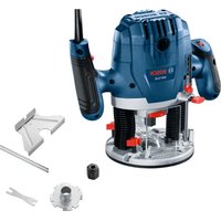
GOF | GMF 1600 CE Professional
Robert Bosch GmbH
Power Tools Division
70745 Leinfelden Echterdingen
Germany
www.bosch-pt.com
2610022197[2012.02]0/256UNI

OCHHNSHOE DYKCGACTTIN
3XCTAYATAH
ukOpnnaIbHaHcpykua3
ECKTAYATBIL
rolnstructioriginale
bgOpHHHAAHHTpyK

BOSCH
snOriginalno upatstvo za rad
slizyima navodila
hrOriginalnuculezrad
etAlgeTare kAsusu suberd
Dr. Egbert Schneider Senior Vice President Engineering
Dr. Eckerhard Strötgen
Engineering Director
PT/ESI
Paa.
Robert Bosch GmbH, Power Tools Division D-70745 Leinfelden-Echterdingen 25.01.2012
Montage
General Power Tool SafetyWarnings
WARNING
Read all safety warnings and all instructions. Failure to follow the warn
and instructions may result in electric shock, fire and/or serious injury.
Save all warnings and instructions for future reference.
The term "power tool" in the warnings refers to your mains-operated (corded) power tool or battery-operated (cordless) power tool.
Work area safety
- Keep work area clean and well lit. Cluttered or dark areas invite accidents.
Do not operate power tools in explosive atmospheres, such as in the presence of flammable liquids, gases or dust. Power tools create sparks which may ignite the dust or fumes. - Keep children and bystanders away while operating a power tool. Distractions can cause you to lose control.
Electrical safety
Power tool plugs must match the outlet. Never modify the plug in any way. Do not use any adapter plugs with earthed (grounded) power tools. Unmodified plugs and matching outlets will reduce risk of electric shock.
- Avoid body contact with earthed or grounded surfaces, such as pipes, radiators, ranges and refrigerators. There is an increased risk of electric shock if your body is earthed or grounded.
Do not expose power tools to rain or wet conditions. Water entering a power tool will increase the risk of electric shock.
Do not abuse the cord. Never use the cord for carrying, pulling or unplugging the power tool. Keep cord away from heat, oil, sharp edges and moving parts. Damaged or entangled cords increase the risk of electric shock.
- When operating a power tool outdoors, use an extension cord suitable for outdoor use. Use of a cord suitable for outdoor use reduces the risk of electric shock.
If operating a power tool in a damp location is unavoidable, use a residual current device (RCD) protected supply. Use of an RCD reduces the risk of electric shock.
Personal safety
Stay alert, watch what you are doing and use common sense when operating a power tool. Do not use a power tool while you are tired or under the influence of drugs, alcohol or medication. A moment of inattention while operating power tools may result in serious personal injury.
Use personal protective equipment. Always wear eye protection. Protective equipment such as dust mask, non-skid safety shoes, hard hat, or hearing protection used for appropriate conditions will reduce personal injuries.
Prevent unintentional starting. Ensure the switch is in the off-position before connecting to power source and/or battery pack, picking up or carrying the tool. Carrying power tools with your finger on the switch or energising power tools that have the switch on invites accidents.
Remove any adjusting key or wrench before turning the power tool on. A wrench or a key left attached to a rotating part of the power tool may result in personal injury.
Do not overreach. Keep proper footing and balance at all times. This enables better control of the power tool in unexpected situations.
Dress properly. Do not wear loose clothing or jewellery. Keep your hair, clothing and gloves away from moving parts. Loose clothes, jewellery or long hair can be caught in moving parts.
If devices are provided for the connection of dust extraction and collection facilities, ensure these are connected and properly used. Use of dust collection can reduce dust-related hazards.
Power tool use and care
Do not force the power tool. Use the correct power tool for your application. The correct power tool will do the job better and safer at the rate for which it was designed.
Do not use the power tool if the switch does not turn it on and off. Any power tool that cannot be controlled with the switch is dangerous and must be repaired.
- Disconnect the plug from the power source and/or the battery pack from the power tool before making any adjustments, changing accessories, or storing power tools. Such preventive safety measures reduce the risk of starting the power tool accidentally.
Store idle power tools out of the reach of children and do not allow persons unfamiliar with the power tool or these instructions to operate the power tool. Power tools are dangerous in the hands of untrained users.
- Maintain power tools. Check for misalignment or binding of moving parts, breakage of parts and any other condition that may affect the power tool's operation. If damaged, have the power tool repaired before use. Many accidents are caused by poorly maintained power tools.
- Keep cutting tools sharp and clean. Properly maintained cutting tools with sharp cutting edges are less likely to bind and are easier to control.
Use the power tool, accessories and tool bits etc. in accordance with these instructions, taking into account the working conditions and the work to be performed. Use of the power tool for operations different from those intended could result in a hazardous situation.
Service
Have your power tool serviced by a qualified repair person using only identical replacement parts. This will ensure that the safety of the power tool is maintained.
SafetyWarnings for Routers
Hold power tool by insulated gripping surfaces, because the cutter may contact its own cord. Cutting a "live" wire may make exposed metal parts of the power tool "live" and shock the operator.
Use clamps or another practical way to secure and support the workpiece to a stable platform. Holding the work by your hand or against the body leaves it unstable and may lead to loss of control.
The allowable speed of the router bit must be at least as high as the maximum speed listed on the power tool. Accessories that rotate faster than permitted can be destroyed.
Router bits or other accessories must fit exactly in the tool holder (collet) of your machine. Routing bits that do not fit precisely in the tool holder of the machine rotate irregularly, vibrate heavily and can lead to loss of control.
Apply the machine to the workpiece only when switched on. Otherwise there is danger of kickback when the cutting tool jams in the workpiece.
- Keep your hands away from the routing area and the router bit. Hold the auxiliary handle or the motor housing with your second hand. When both hands hold the machine, they cannot be injured by the router bit.
- Never cut over metal objects, nails or screws. The router bit can become damaged and lead to increased vibrations.
Use suitable detectors to determine if utility lines are hidden in the work area or call the local utility company for assistance. Contact with electric lines can lead to fire and electric shock. Damaging a gas line can lead to explosion. Penetrating a water line causes property damage or may cause an electric shock.
Do not use blunt or damaged router bits. Blunt or damaged router bits cause increased friction, can become jammed and lead to imbalance.
When working with the machine, always hold it firmly with both hands and provide for a secure stance. The power tool is guided more secure with both hands.
Secure the workpiece. A workpiece clamped with clamping devices or in a vice is held more secure than by hand.
Always wait until the machine has come to a complete stop before placing it down. The tool insert can jam and lead to loss of control over the power tool.
Products sold in GB only: Your product is fitted with an BS 1363/A approved electric plug with internal fuse (ASTA approved to BS 1362).
If the plug is not suitable for your socket outlets, it should be cut off and an appropriate plug fitted in its place by an authorised customer service agent. The replacement plug should have the same fuse rating as the original plug.
The severed plug must be disposed of to avoid a possible shock hazard and should never be inserted into a mains socket elsewhere.
Products sold in AUS and NZ only: Use a residual current device (RCD) with a rated residual current of 30 mA or less.
20|English
Product Description and Specifications

Read all safety warnings and all instructions. Failure to follow the warnings and instructions may result in electric shock, fire and/or serious injury.
While reading the operating instructions, unfold the graphics page for the machine and leave it open.
Intended Use
The machine is intended for routing grooves, edges, profiles and elongated holes as well as for copy routing in wood, plastic and light building materials, while resting firmly on the workpiece.
With reduced speed and with appropriate routing bits, nonferrous alloys can also be machined.
Product Features
The numbering of the product features refers to the illustration of the machine on the graphics page.
1 Routing motor
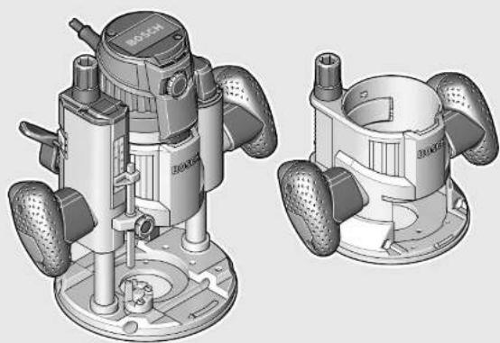
2 Plunge base
3 Non-plunge base
4 Handle (insulated gripping surface)
5 Adjustment knob for fine adjustment of depth-of-cut (plunge base)
6 Scale for depth-of-cut fine adjustment
7 Release lever for plunge action
8 Index mark for fine adjustment
9 Scale for depth-of-cut adjustment (plunge base)
10 Slide with index mark (plunge base)
11 Depth stop (plunge base)
12 Turret stop
13 Base plate
14 Guide plate
15 Thumbwheel for speed preselection
16 Knurled screw for depth stop (plunge base)
17 Tightening nut with collet
18 Router bit
19 Lock-on button for On/Off switch
20 On/Off switch
21 Securing latch for removal of motor
22 Clamping lever for plunge base/non-plunge base
23 Seat for parallel guide rods
24 Adjustment knob for depth-of-cut fine adjustment (nonplunge base)
25 Clamping lever for depth-of-cut coarse adjustment (nonplunge base)
26 Coarse adjustment notches for non-plunge base
27 Spindle lock button
28 Open-end spanner, size 24 mm
29 Knurled screw for extraction adapter(2x)
30 Extraction adapter (plunge base)
31 Extraction hose (0 35 mm)
32 Extraction adapter (non-plunge base)
33 Intermediate ring for extraction adapter (non-plunge base)
34 Scale for depth-of-cut adjustment (non-plunge base)
35 Parallel guide
36 Guide rod for parallel guide (2x)^
37 Wing bolt for fine adjustment of parallel guide (2x)^
38 Wing bolt for coarse adjustment of parallel guide (2x)^
39 Fine-adjustment knob for parallel guide
40 Adjustable edge guide for parallel guide
41 Wing bolt for guide rods of parallel guide (2x)^
42 Router compass/guide-rail adapter
43 Router compass handle
44 Wing bolt for coarse adjustment of router compass (2x)^
45 Wing bolt for fine adjustment of router compass (1x)
46 Fine-adjustment knob for router compass
47 Centring screw for compass stop
48 Base spacer (included in the "router compass" set)
49 Guide rail
50 SDS guide-bushing adapter
51 Fastening screw for guide bushing adapter (2x)
52 Release lever for guide bushing adapter
53 Guide bushing
54 Fastening screw for guide plate
55 Centring pin
56 Fastening screws for non-plunge base
57 Specialty Allen key for depth-of-cut fine adjustment (non-plunge base)
58 Extension for depth-of-cut fine adjustment (non-plunge base)*
59 Extraction hood for edge routing
60 Fastening screw for extraction hood
*Accessories shown or described are not part of the standard delivery scope of the product. A complete overview of accessories can be found in our accessories program.
English | 21
Technical Data
| Multifunction Router GOF 1600 CE GMF 1600 CE | |||
| Article number | 3601 F24 0.. 3601 F24 0.. | ||
| Rated power input | W | 1 | 6 |
| No-load speed | min-1 | 10000 - 25000 | 10000 - 25000 |
| Speed preselection | ● | ● | |
| Constant electronic control | ● | ● | |
| Connection for dust extraction | ● | ● | |
| Tool holder | mm | 8 - 12 | 8 - 12 |
| inch | 1/4 - 1/2 | 1/4 - 1/2 | |
| Plunge depth (plunge base) | mm | 76 | 76 |
| Weight according to EPTA-Procedure 01/2003 | |||
| - Contour router | kg | - | 4.3 |
| - Plunge router | kg | 5.8 | 5.8 |
| Protection class | ☐/☐ | ☐/☐ | |
| The values given are valid for a nominal voltage [U] of 230 V. For different voltages and models for specific countries, these values can vary. | |||
Noise/Vibration Information
Measured sound values determined according to EN 60745.
Typically the A-weighted noise levels of the product are: Sound pressure level 86 dB(A); Sound power level 97 dB(A). Uncertainty K = 3 dB.
Wear hearing protection!
| Routing with Non-plunge Base | Routing with Plunge Base | ||
| Vibration total values an (triax vector sum) and uncertainty K determined according to EN 60745: | |||
| an | m/s2 | =6.0 | =5.5 |
| K | m/s2 | =1.5 | =1.5 |
The vibration emission level given in this information sheet has been measured in accordance with a standardised test given in EN 60745 and may be used to compare one tool with another. It may be used for a preliminary assessment of exposure.
The declared vibration emission level represents the main applications of the tool. However if the tool is used for different applications, with different accessories or poorly maintained, the vibration emission may differ. This may significantly increase the exposure level over the total working period.
An estimation of the level of exposure to vibration should also take into account the times when the tool is switched off or when it is running but not actually doing the job. This may significantly reduce the exposure level over the total working period.
Identify additional safety measures to protect the operator from the effects of vibration such as: maintain the tool and the accessories, keep hands warm, organise work patterns.
Declaration of Conformity C
We declare under our sole responsibility that the product described under "Technical Data" is in conformity with the following standards or standardization documents: EN 60745 according to the provisions of the directives 2011/65/EU, 2004/108/EC, 2006/42/EC.
Technical file (2006/42/EC) at:
Robert Bosch GmbH, PT/ETM9,
D-70745 Leinfelden-Echterdingen
Dr. Egbert Schneider
Senior Vice President
Engineering
Dr. Eckerhard Strötgen
Engineering Director
PT/ESI

Robert Bosch GmbH, Power Tools Division
D-70745 Leinfelden-Echterdingen
25.01.2012
Assembly
Before any work on the machine itself, pull the mains plug.
Inserting the Routing Motor into the Plunge Base/Non-plunge Base (see figures A-B)
- Open the clamping lever for the plunge base/non-plunge base 22.
- Push the routing motor to the stop into the plunge base/non-plunge base.
- When using the non-plunge base 3, press clamping lever 25 and slide the routing motor 1 up or down to the desired
22|English
position in the non-plunge base 3, until it, with the clamping lever 25 released, engages in one of the 3 notches 26.
- Shut the clamping lever for the plunge unit/non-plunge base 22.
- Adjust the required depth-of-cut; see Section "Adjusting the Depth-of-cut".
Separating the Routing Motor from the Plunge Unit/Nonplunge Base (see figure C)
- Open the clamping lever for the plunge base/non-plunge base 22.
- Pull the routing motor to the stop and and hold it in this position.
- Press securing latch 21 and pull the routing motor completely out of the plunge base/non-plunge base. When using the non-plunge base 3, additionally press clamping lever 25.
Inserting a Router Bit (see figure D)
It is recommended to wear protective gloves when inserting or replacing router bits.
Depending on the application, router bits are available in the most different designs and qualities.
Router bits made of high speed steel (HSS) are suitable for the machining of soft materials, e.g. softwood and plastic.
Carbide tipped router bits (HM) are particularly suitable for hard and abrasive materials, e. g. hardwood and aluminium.
Original router bits from the extensive Bosch accessories program are available at your specialist shop.
Use router bits with a shank diameter of 1.2mm as far as this is possible. Only use clean router bits that are in perfect condition.
The router bit can be changed when the routing motor is mounted in the plunge base/non-plunge base. However, it is recommended to change the tool with the routing motor dismounted.
- Remove the routing motor from the plunge base/nonplunge base.
- Press and hold the spindle lock button 27 (1). If required, turn the spindle by hand until the lock engages. Actuate the spindle lock button 27 only when at a standstill.
- Loosen the tightening nut 17 with the open-end spanner 28 (size 24mm ) by turning in anticlockwise direction (2).
- Insert the router bit into the collet. The shank of the router bit must be immersed at least 20mm into the collet.
- Tighten the tightening nut 17 with the open-end spanner 28 (size 24mm ) by turning in clockwise direction. Release the spindle lock button 27.
Do not insert a router bit with a diameter larger than 50mm when the guide bushing is not mounted. Such router bits do not fit through the base plate.
Do not tighten the tightening nut of the collet without a router bit inserted. Otherwise the collet can be damaged.
Dust/Chip Extraction
Dusts from materials such as lead-containing coatings, some wood types, minerals and metal can be harmful to
one's health. Touching or breathing-in the dusts can cause allergic reactions and/or lead to respiratory infections of the user or bystanders.
Certain dusts, such as oak or beech dust, are considered as carcinogenic, especially in connection with wood-treatment additives (chromate, wood preservative). Materials containing asbestos may only be worked by specialists.
- As far as possible, use a dust extraction system suitable for the material.
- Provide for good ventilation of the working place.
- It is recommended to wear a P2 filter-class respirator.
Observe the relevant regulations in your country for the materials to be worked.
Prevent dust accumulation at the workplace. Dusts can easily ignite.
Mounting the Extraction Adapter to the Plunge Base (see figure E)
The extraction adapter 30 can be mounted with the hose connection facing toward the front or rear. When the guide-bushing adapter 50 is inserted, it may be required to mount the guide-bushing adapter turned by 180^ so that the extraction adapter 30 does not touch the release lever 52. Fasten the extraction adapter 30 with the 2 knurled screws 29 to the base plate 13.
To ensure optimum extraction, the extraction adapter 30 must be cleaned regularly.
Mounting the Extraction Adapter to the Non-plunge Base (see figure F)
The extraction adapter 32 can be mounted with the hose connection facing toward the front or rear. When the guide-bushing adapter 50 is inserted, fasten the extraction adapter 32 with the 2 knurled screws 29 to the base plate 13. For applications without the guide-bushing adapter 50, firstly mount the intermediate ring 33 to the extraction adapter 32, as shown in the figure.
Connecting the Dust Extraction
Insert an extraction hose (0 35 mm) 31 (accessory) into the mounted extraction adapter. Connect the extraction hose 31 to a vacuum cleaner (accessory).
The machine can be plugged directly into the receptacle of a Bosch all-purpose vacuum cleaner with remote starting control. The vacuum cleaner starts automatically when the machine is switched on.
The vacuum cleaner must be suitable for the material being worked.
When vacuuming dry dust that is especially detrimental to health or carcinogenic, use a special vacuum cleaner.
Operation
Starting Operation
Observe correct mains voltage! The voltage of the power source must agree with the voltage specified on the nameplate of the machine. Power tools marked with 230V can also be operated with 220V .
English | 23
Preselecting the Speed
The required speed can be preselected with the thumbwheel 15 (also while running).
1-2 low speed
3-4 medium speed
5-6 high speed
The values shown in the chart are standard values. The necessary speed depends on the material and the operating conditions, and can be determined by practical testing.
| Material Router bit | diameter (mm) | Thumbwheel 15 |
| Hardwood (Beech) 4-10 | 5-6 | |
| 12-20 | 3-4 | |
| 22-40 | 1-2 | |
| Softwood (Pine) | 4-10 | 5-6 |
| 12-20 | 3-6 | |
| 22-40 | 1-3 | |
| Particle Board | 4-10 | 3-6 |
| 12-20 | 2-4 | |
| 22-40 | 1-3 | |
| Plastics | 4-15 | 2-3 |
| 16-40 | 1-2 | |
| Aluminium | 4-15 | 1-2 |
| 16-40 | 1 |
After longer periods of working at low speed, allow the machine to cool down by running it for approx. 3 minutes at maximum speed with no load.
Switching On and Off
Adjust the depth-of-cut before switching on or off; see Section "Adjusting the Depth-of-cut".
To start the machine, press the On/Off switch 20 and keep it pressed.
To lock the pressed On/Off switch 20, press the lock-on button 19.
To switch off the machine, release the On/Off switch 20 or when it is locked with the lock-on button 19, briefly press the On/Off switch 20 and then release it.
When not using the power tool, switch it off in order to save energy.
Constant Electronic Control
Constant electronic control holds the speed constant at no-load and under load, and ensures uniform working performance.
Soft Starting
The electronic soft starting feature limits the torque upon switching on and increases the working life of the motor.
Adjusting the Depth-of-cut
The adjustment of the depth-of-cut may only be carried out when the router is switched off.
Adjusting the Depth-of-cut on the Plunge Base (see figure G)
For coarse adjustment of the depth-of-cut, proceed as follows:
- Place the machine with the router bit mounted on the workpiece to be machined.
- Set the scale for fine adjustment 6 to "0".
- Set the turret stop 12 to the lowest setting; the turret stop can be felt to engage.
Loosen the knurled screw at depth stop 16, so that the depth stop 11 moves freely. - Press the release lever for plunge action 7 down and slowly guide the router down until the router bit 18 touches the workpiece surface. Let go of release lever 7 again to lock this plunging depth.
Push the depth stop 11 down until it faces against the turret stop 12. Set the slide with the index mark 10 to the "0" position on the scale for depth-of-cut adjustment 9. - Set the depth stop 11 to the desired routing depth and tighten the knurled screw 16 for the depth stop. Take care not to misadjust the slide with the index mark 10.
Press the release lever for plunge action 7 and guide the router to the uppermost position.
The set routing depth is only reached when depth stop 11 touches the turret stop 12 while plunging.
For deep cuts, it is recommended to carry out several cuts, each with little material removal. By using the turret stop 12, the cutting process can be divided into several steps. For this, adjust the desired depth-of-cut to the lowest step of the turret stop and select the higher steps first for the initial cuts. The clearance of the steps is approx. 3.2mm
After a trial cut, the depth-of-cut can be set exactly to the desired measure by turning the adjustment knob 5; turn in clockwise direction to increase the cutting depth and in anticlockwise direction to decrease the cutting depth. The scale 6 can be used for guidance. One full turn corresponds with a setting range of 1.5mm ; a graduation mark on the top edge of the scale 6 corresponds with a 0.1mm change of the setting range. The maximum setting range is ± 16mm .
Example: The desired depth-of-cut is to be 10.0mm ; the trial cut resulted in a cutting depth of 9.6mm .
- Press the release lever for plunge action 7 and guide the router to the uppermost position.
Turn adjustment knob 5 by 0.4mm / 4 graduation marks (difference from nominal to actual value) in clockwise direction. - Check the selected depth-of-cut by carrying out another trial cut.
When fine-adjusting the routing depth, take care that the index mark 8 on the side of the plunge base points towards the centre imprinted line. This measure ensures that there is sufficient travel in both directions for readjustment of the plunge depth.
When the plunge base 2 is lowered to the maximal plunge depth, cutting deeper by means of the fine adjustment is not possible, as the maximum travel has been utilised.
Fine adjustment is also not possible when the depth stop 11 faces against the turret stop 12.
24|English
Adjusting the Depth-of-cut on the Non-plunge Base (see figure H)
For adjustment of the depth-of-cut, proceed as follows: - Open the clamping lever for the non-plunge base 22.
Coarse pre-adjustment of the routing depth is possible in 3 steps. For this, press clamping lever 25 and slide the routing motor 1 up or down in the non-plunge base 3, until it, with the clamping lever 25 released, is locked in one of the 3 notches 26. The notches each have a clearance of 12.7mm (0.5").
The adjustment knob for depth-of-cut fine adjustment 24 is used for fine adjustment of the routing depth; turn clockwise to increase the routing depth, and anticlockwise to decrease the routing depth. The travel on the scale of adjustment knob 24 is indicated in inch and millimeter. The maximum setting range is 41mm . The scale for depth-of-cut adjustment 34 provides added orientation.
Example: The desired depth-of-cut is to be 10.0mm ; the trial cut resulted in a cutting depth of 9.5mm .
- Set the scale of the adjustment knob 24 to "0" without changing the setting of the adjustment knob 24 itself. Then set the adjustment knob 24 to the value "0.5" by turning in clockwise direction.
- Check the selected depth-of-cut by carrying out another trial cut.
Working Advice
Direction of Feed and Routing Process (see figure I)
The routing process must always be carried out against the rotation direction of the router bit 18 (up-cutting motion). When routing in the direction with the rotation of the router (down-cutting), the machine can break loose, eliminating control by the user.
For routing with the plunge base 2, proceed as follows:
- Adjust the required depth-of-cut; see Section "Adjusting the Depth-of-cut".
- Place the machine with the router bit mounted on the workpiece to be machined and switch the power tool on.
Press the release lever for plunge action 7 down and slowly guide the router down until the set depth-of-cut is reached. Let go of release lever 7 again to lock this plunging depth. - Carry out the routing process applying uniform feed
- After finishing the routing process, guide the router up to the uppermost position.
- Switch the power tool off.
For routing with the non-plunge base 3, proceed as follows:
Note: Take into consideration that for routing work with the non-plunge base 3, the router bit 18 always protrudes out of the base plate 13. Do not damage the template or the workpiece. - Adjust the required depth-of-cut; see Section "Adjusting the Depth-of-cut".
- Switch the machine on and guide it to the location subject to routing.
- Carry out the routing process applying uniform feed.
- Switch the power tool off. Do not place the power tool down until the router bit has come to a standstill.
Routing with Auxiliary Guide (see figure J)
For working large workpieces, e. g., when routing grooves, a board or straight edge can be securely fastened to the workpiece as an auxiliary guide. The multifunction router can be guided alongside the path of this auxiliary guide. When using the plunge base 2, guide the guide plate (flattened side) of the multifunction router alongside the auxiliary guide.
Shaping or Molding Applications
For shaping or molding applications without the use of a parallel guide, the router bit must be equipped with a pilot or a ball bearing.
Guide the switched on power tool from the side toward the workpiece until the pilot or the ball bearing of the router bit faces against the workpiece edge to be machined.
Guide the power tool alongside the workpiece edge with both hands, paying attention that the router is positioned rectangular. Too much pressure can damage the edge of the workpiece.
Routing with Parallel Guide (see figure K)
Slide the parallel guide 35 with the guide rods 36 into the base plate 13 and tighten as required with the wing bolts 41. Additionally, the parallel guide can be adjusted lengthwise with the wing bolts 37 and 38.
Fine adjustment of the length is possible with the fine-adjustment knob 39 after loosening both wing bolts 37. One revolution corresponds with a setting range of 2.0mm . One graduation mark on the fine-adjustment knob 39 changes the setting range by 0.1mm .
The effective contact surface of the parallel guide can be adjusted with the edge guide 40.
Guide the switched on power tool with uniform feed and lateral pressure on the parallel guide alongside the workpiece edge.
Routing with the Router Compass (see figure L)
The router compass/guide-rail adapter 42 can be used for circular routing jobs. Mount the router compass as shown in the figure.
Screw the centring screw 47 into the thread on the router compass. Insert the point of the centring screw into the centre of the circular arc to be routed, paying attention that point of the screw engages into the workpiece surface.
Coarsely adjust the required radius by moving the router compass and tighten the wing bolts 44 and 45.
The length can be fine adjusted with the fine-adjustment knob 46 after loosening the wing bolt 45. One revolution corresponds with a setting range of 2.0mm . One graduation mark on the fine-adjustment knob 46 changes the setting range by 0.1mm .
Guide the switched on power tool over the workpiece with the right handle 4 and the router compass handle 43.
Routing with Guide Rail (see figure M)
Straight routing cuts can be carried out with help of the guide rail 49.
The base spacer 48 must be mounted in order to compensate the height difference.
Mount the router compass/guide-rail adapter 42 as shown in the figure.
Fasten the guide rail 49 to the workpiece with suitable clamping devices, e. g. screw clamps. Place the machine with the guide-rail adapter 42 mounted onto the guide rail.
Routing with Guide Bushing (see figures N-Q)
The guide bushing 53 enables template and pattern routing on workpieces.
In order to use the guide bushing 53, the guide bushing adapter 50 must be inserted into the guide plate 14 first.
Place the guide bushing adapter 50 from above onto the guide plate 14 and tighten it firmly with the 2 fastening screws 51. Pay attention that the release lever for the guide bushing adapter 52 is freely movable.
Choose a suitable guide bushing, depending on the thickness of the template or the pattern. Because of the projecting height of the guide bushing, the template must have a minimum thickness of 8mm .
Actuate the release lever 52 and insert the guide bushing 53 from below into the guide bushing adapter 50. Ensure that the encoding keys clearly engage in the grooves of the guide bushing.
Check the clearance from router bit centre and guide bushing edge, see section "Centring the Base Plate".
- Select a router bit with a diameter smaller than the interior diameter of the guide bushing.
For routing with the guide bushing 53 proceed as follows:
Note: Take into consideration that for routing work with the non-plunge base 3, the router bit 18 always protrudes out of the base plate 13. Do not damage the template or the workpiece.
-Guide the switched on power tool with the guide bushing toward the template.
- When using the plunge base 2: Press the release lever for plunge action 7 down and slowly guide the router down until the set depth-of-cut is reached. Let go of release lever 7 again to lock this plunging depth.
Guide the switched on power tool with the protruding guide bushing alongside the template applying lateral pressure.
Centring the Base Plate (see figure R)
To ensure that the distance from router bit centre and guide bushing edge is uniform, the guide bushing and the guide plate can be adjusted to each other, if required.
- When using the plunge base 2: Press the release lever for plunge action 7 down and guide the router toward the base plate to the stop. Let go of release lever 7 again to lock this plunging depth.
Loosen fastening screws 54 approx. 2 turns, so that guide plate 14 can move freely. -
Insert the centring pin 55 into the tool holder as shown in the figure. Hand-tighten the tightening nut so that the centring pin can still be moved freely.
Align the centring pin 55 and the guide bushing 53 to each other by slightly moving the guide plate 14.
Retighten the fastening screws 54 again. -
Remove the centring pin 55 from the tool holder.
- When using the plunge base 2: Press the release lever for plunge action 7 and guide the router back to the upper-most position.
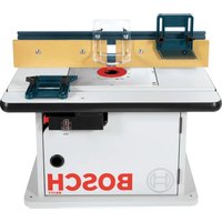
Operation with RouterTable(see figureS)
The non-plunge base 3 can be used with a suitable router table. To install the router, remove the guide plate 14 and fasten the non-plunge base 3 to the router table with the fastening screws 56.
For mounting of the non-plunge base, please observe the operating instructions of your router table. If necessary, matching holes must be drilled into the router table in order to mount the non-plunge base.
For fine adjustment of the depth-of-cut, it is best to use the extension 58 or the specialty Allen key 57.
Routing with Extraction Hood (see figures T-U)
For routing edges, the extraction hood 59 can additionally be used.
- Fasten the extraction hood 59 with the 2 fastening screws 60 to the base plate 13. The extraction hood 59 can be fastened in 3 different positions, as shown in the figure.
- Remove the extraction hood again for routing smooth plane surfaces.
Maintenance and Service
Maintenance and Cleaning
Before any work on the machine itself, pull the mains plug.
For safe and proper working, always keep the machine and ventilation slots clean.
In extreme conditions, always use dust extraction as far as possible. Blow out ventilation slots frequently and install a residual current device (RCD). When working metals, conductive dust can settle in the interior of the power tool. The total insulation of the power tool can be impaired.
If the replacement of the supply cord is necessary, this has to be done by Bosch or an authorized Bosch service agent in order to avoid a safety hazard.
If the machine should fail despite the care taken in manufacturing and testing procedures, repair should be carried out by an after-sales service centre for Bosch power tools.
In all correspondence and spare parts order, please always include the 10-digit article number given on the type plate of the machine.
After-sales Service and Customer Assistance
Our after-sales service responds to your questions concerning maintenance and repair of your product as well as spare parts. Exploded views and information on spare parts can also be found under:
www.bosch-pt.com
Our customer service representatives can answer your questions concerning possible applications and adjustment of products and accessories.
26 | Français
Great Britain
Robert Bosch Ltd. (B.S.C.)
P.O.Box 98
Broadwater Park
North Orbital Road
Denham
Uxbridge
UB95HJ
Tel. Service: +44 (0844) 736 0109
Fax:+44(0844)7360146
E-Mail: boschservicecentre@bosch.com
Ireland
Origo Ltd.
Unit 23 Magna Drive
Magna Business Park
City West
Dublin 24
Tel. Service: +353 (01) 4666700
Fax:+353(01)4666888
Australia, New Zealand and Pacific Islands
Robert Bosch Australia Pty. Ltd.
Power Tools
Locked Bag 66
Clayton South VIC 3169
Customer Contact Center
Inside Australia:
Phone: +61 (01300) 307 044
Fax: +61 (01300) 307 045
Inside New Zealand:
Phone: +64 (0800) 543 353
Fax:+64(0800)428570
Outside AU and NZ:
Phone: +61 (03) 9541 5555
www.bosch.com.au
Republic of South Africa
Customer service
Hotline: +27 (011) 6519600
Gauteng - BSC Service Centre
35 Roper Street, New Centre
Johannesburg
Tel.: +27 (011) 4939375
Fax:+27(011)4930126
E-Mail: bsctools@icon.co.za
KZN - BSC Service Centre
Unit E, Almar Centre
143 Crompton Street
Pinetown
Tel.: +27 (031) 7012120
Fax:+27(031)7012446
E-Mail: bsc.dur@za.bosch.com
Western Cape - BSC Service Centre
Democracy Way, Prosperity Park
Milnerton
Tel.: +27 (021) 5512577
Fax: +27 (021) 5513223
E-Mail: bsc@zsd.co.za
Bosch Headquarters
Midrand, Gauteng
Tel.: +27 (011) 6519600
Fax:+27(011)6519880
E-Mail: rbsa-hq.pts@za.bosch.com
Disposal
The machine, accessories and packaging should be sorted for environmental-friendly recycling.
Do not dispose of power tools into household waste!
Only for EC countries:
According to the European Guideline 2002/96/EC for Waste Electrical and Electronic Equipment and its implementation into national right, power tools that are no longer usable must be collected separately and disposed of in an environmentally correct manner.
Subject to change without notice.
Français
Senior Vice President Engineering
Dr. Eckerhard Strötgen
Engineering Director PT/ESI
Paa Maaa i.v. Mojgc
Robert Bosch GmbH, Power Tools Division
D-70745 Leinfelden-Echterdingen
25.01.2012
Montage
Robert Bosch (France) S.A.S.
Dr. Egbert Schneider Senior Vice President Engineering
Dr. Eckerhard Strögtgen
Engineering Director
PT/ESI
ppa. 1000 i.v. nuOycu
Robert Bosch GmbH, Power Tools Division D-70745 Leinfelden-Echterdingen 25.01.2012
Montaje
Senior Vice President
Engineering
Dr. Eckerhard Strötgen
Engineering Director
PT/ESI


Robert Bosch GmbH, Power Tools Division
D-70745 Leinfelden-Echterdingen
25.01.2012
Montagem
- Antes de todoseworkos na ferramenta electrica develerpauxar a ficha de rede da tomada.
Dr. Egbert Schneider Senior Vice President Engineering
Dr. Eckerhard Strötgen Engineering Director PT/ESI


Robert Bosch GmbH, Power Tools Division D-70745 Leinfelden-Echterdingen 25.01.2012
Montaggio
Dr. Egbert Schneider Senior Vice President Engineering
Dr. Eckerhard Strötgen Engineering Director PT/ESI


Robert Bosch GmbH, Power Tools Division D-70745 Leinfelden-Echterdingen 25.01.2012
Montage
Dr. Egbert Schneider Senior Vice President Engineering
Dr. Eckerhard Strötgen
Engineering Director
PT/ESI


Robert Bosch GmbH, Power Tools Division D-70745 Leinfelden-Echterdingen 25.01.2012
Montering
Bosch Service Center
Telegrafvej 3
2750 Ballerup
TIf. Service Center: +45 (4489) 8855
Fax:+45(4489)8755
E-Mail: vaerktoej@dk.bosch.com
Bortskaffelse
Dr. Egbert Schneider Senior Vice President Engineering
Dr. Eckerhard Strötgen
Engineering Director
PT/ESI

Robert Bosch GmbH, Power Tools Division D-70745 Leinfelden-Echterdingen 25.01.2012
Montage
Bosch Service Center
Telegrafvej 3
2750 Ballerup
Danmark
Tel.: +46 (020) 41 44 55
Fax:+46(011)187691
Avfallshantering
50 SDS-kopieringshylseadapter
51 Festeskrue for kopieringsyhelseadapteren (2x)
52 Lasespak for kopieringshylseadapteren
53 Kopieringshylse
54 Festeskrue for glideplaten
55 Sentreringsspiss
56 Festeskrueer for kopieringsenhet
57 Spesial-sekskantnokkel for freesedybde-fininnstilling (kopieringshenhet)*
58 Forlengelse for fresedybde-fininnstilling (kopieringshenet)*
Senior Vice President
Engineering
Dr. Eckerhard Strötgen
Engineering Director
PT/ESI

Robert Bosch GmbH, Power Tools Division
D-70745 Leinfelden-Echterdingen
25.01.2012
Montering
Senior Vice President
Engineering
Dr. Eckerhard Strötgen
Engineering Director
PT/ESI
ppaaee i.v. nuoyn
Robert Bosch GmbH, Power Tools Division
D-70745 Leinfelden-Echterdingen
25.01.2012
96 | Suomi
Asennus
Dr. Egbert Schneider Senior Vice President Engineering
Dr. Eckerhard Strötgen
Engineering Director
PT/ESI


Robert Bosch GmbH, Power Tools Division D-70745 Leinfelden-Echterdingen 25.01.2012
EuvaopAoynon
Na amevepyonoieite to nAekptipko epyaole otav dev to xnpouoioic. EToI eOIOVOpC cvpocia.
Hektpovikn oBepooinon
HnKtprovikn staOcponoin jbiatnpci tv apioo tpoapov oxedov staepekai xupic kai peopio kai eepaoaalci Teyn oiaopoo andoan epyaianac.
OmaHekkvion
Hncktpovikn qaa nckivnon nepiopicn ton ponnt opceync kata n th eon oe aeitoupyia kal auEve t etai tn diapkeia zwnc tou kivnpa.
PouonbaouocpecapapatoC
Hpuoanoubaocpaeapaoatopneeneva dieyatai mvootav tonktpkoepyaiaoeixteei kctcacourpyiac.
Pou Tou aouc ppeapiaopocn ovaa bua (beta ekuova G)
Tnnpo0mou ton Baooc pceapiaopatacakokouohote TnyEcdiabikaia:
Aakumnte to nAekpiok epyaieo aui eTo auvaipooynuévo epaieo pcpapiaopocnaw oTo unkatepyaia Teayio.
- Tuplntv kaijaka mukopouoian6 oto 0
Puoiote Tov nepiotpeoepoevo obnyo 12 otynio xanai a i d a .O nepiotepoepoevo oobyoc aoaiaieiaognta.
AutaTe Tn BiaPe auakwn KcpaH 16 otov oyO bOouc yia va mopei va kveitr aeueepo a oyoc bOouc 11.
Pnntne npoc ta kato xoiao anopavdaawonc 7 via tn Aetoupyia buoianc kai oynote tny kaotepa aay aya npoc ta kato wepin npce2a 18 va ayileeivn emapveia Tou no katcpyiaea Teayiou. Aophote to poxao anopavdaawonc 7 naie ehepepo. Etaupuitctai otahepa to Baooc Buianc.
- Pntnnte npoc ta kawtov oyno foouc 11 xpa va oukounnei enawov tropepeoevo onyo 12 PuBtiote to ouptn ieveblktn 10 om theo nO otny Klaoka faouc opepaiaqatc9.
PuBIOIeTovobnyoBaBOUC11OToemBuunTO BBOOC apcApauaTOC kAphiTeOTOVbNOBbOuTN BIDA uauakwnKePAH 16.PooEETVAUNETAKiVnTeoiOpuntnc meEvdoKIn 10
Pntnoe npoc ta kaTow to oxo anouavdaawong 7 yia n T Aetoupyia BuOnc kai obnyote tn v kaTe m pEa otny avotatn Bcog.
To pueaueo Baooc, ppezapiaotoc emtuayveetai mvo otav o onyoc Baooc 11 akoumnneoi otov nepiatpepoevo onyo 12.
Na ppeapete meyala bthn dieyovrac noa ppeapiaata to eva peto a 0Aoo me kipoh apaioe uikou kae oppa. Me tonbceioupiatppeopcvou neoyu 12 npocrcv ia unodiaapeote to ppeapiaoe ae mennnae Baahec.
autu puoiote to emounto baoc opecapiaatoc me tvn mo xannnbaaiiaouo odnyouk aokaoouwacipxotnykatepyaiaenayoyvatcavitotoixecu npniotepc Baaibc. Hanotaan avaeaa otic baiecavexpctar 3,2 mm nepinou.
Meta an eva dokaatko pefapiaqa umopeite va uthetace to faooc pefapiaotc me akipieia yupizovac to nepiatapefove koumi 5. Ta va auhacte to faooc pefapiaotc touviote me woloayakn fop, ia va cattataoe to faooc pefapiaotc uovite me fop a vntet ntc woloayankc. H kaiaka 6 ecumptete otov npaaavatoiao oac. Mia neipiatpoh avitatoxe ie diaobogun puoianc 1.5 mm, ma unosiaican oto endw tna tnc kaiakac 6 avitatoxe ie metaBoah ntc diaobopuc pouianc kata 0.1 mm. H ueyian diaobopun pohuan avexetar oe ± 16 mm.
Tnpoue to dikaiwmaaayv.
Türkce
Güvenlik Talimatu
Elektrikl El Aletleri icin Genel Uyarı Talimat 1UXAFButün uyarllar ytalimat hukumlern
Dr. Egbert Schneider Senior Vice President Engineering
Dr. Eckerhard Strötgen
Engineering Director
PT/ESI
Paa.
Robert Bosch GmbH, Power Tools Division D-70745 Leinfelden-Echterdingen 25.01.2012
Türkce|113
Montaj
Bosch San. ve Tic. A.S.
Ahi Evran Cad. No:1 Kat:22
Polaris Plaza
80670 Maslak/Istanbul
Bosch Uzman Ekibi +90 (0212) 367 1888
Tasfiye
Dr. Egbert Schneider Senior Vice President Engineering
Dr. Eckerhard Strötgen
Engineering Director
PT/ESI

Robert Bosch GmbH, Power Tools Division D-70745 Leinfelden-Echterdingen 25.01.2012
Montaž
System Constant Electronic
Robert Bosch Sp. z o.o.
Dr. Egbert Schneider Senior Vice President Engineering
Dr. Eckerhard Strötgen
Engineering Director
PT/ESI

Robert Bosch GmbH, Power Tools Division D-70745 Leinfelden Echterdingen 25.01.2012
Montáž
Bosch Service Center PT
K Vapence 1621/16
69201 Mikulov
Dr. Egbert Schneider Senior Vice President Engineering
Dr. Eckerhard Strötgen
Engineering Director
PT/ESI


Robert Bosch GmbH, Power Tools Division D-70745 Leinfelden-Echterdingen 25.01.2012
Montáž
Senior Vice President
Engineering Director
Engineering

Robert Bosch GmbH, Power Tools Division
D-70745 Leinfelden-Echterdingen
25.01.2012
Magyar | 147
Osszeszerelés
IpoHTTE BcE yKa3aHHN HhCTpyKuH NTO TexHKe
6e3oTachocnH. Hec6bAoHeHneYka3aHHN NHCtpyKuH N ToTexNHke 6e3oTachocnMoXet CTaB TpHUNHOIPOpaKeHmnaEAEKTPuecknM TKOM, POkapa nTRKeAbxTpaBM.
CoxpaHnIte 3TH HNCTpyKuHH N yKa3aHHA DAA 6yAyueero hctoA3OBAHH.
NCTOa3oBaHHOe B HAcTOAUXHnCtpyuHX N yKa3AHHX TOHnHE 3AEKTPOHnCTpyMeHT pACPPOCTpAHHeTc HA 3AEKTPOHnCTpyMeHT C nIHATHeM O T cETH (C cTeEBIM SHypOM) N ha AKAyMaIATOpBn 3AEKTPOnHnCTpyMeHT (6e3 cTeBOrO shypa).
Be30nachochtb pa6oeryo mecta
CoepxHpepaOooMeTOBCHOTHXopo0o OCbeeHHbIM.BecTOpRAOKnHEOCBeeHHbIeyAcTKn paOooeroMeCTaMOryTPINBECTHKHeCuaTbMcayqAAM.
He pa6oTaIe C 3THM 3AekTPOHNCTPymeHtOM BO BpBBOOANTACHOM TOMeEHN, B KOTOPM HAXOARTC ROpOHue KXKOCTH, BOCTAAmeHOUHECRA3bH HAN TbAb. 3AekTPOHNCTPymeHTb NCKPT, YTO MOKET PIPBECTN K BOCTAAmeEHHIO TbAH HAN IAPOB.
BoBpMa pa60Tb C AKeTPOHHCTpyMeHToM He OYONCKAeKBOaewy paOoey MeCyTeerN IOTOPOHHXuU.OTBAeKuChB, Bbo MokeTe NToTePrtb KOHTPOAb HAD AKeTPOHHCTpyMeHToM.
3aektpo6e3oanachoctb
HTeTceBHaBHAKA3AEKTPOHCTPymEHTa DOAXHn IOXoAHbTK WTeTCEBHOH PO3ETKE. Hn B KOem CAYae HeM3MeHHte TTECtEBHyO BHAKy. He pMHmHHe TepExoHbIe TKepebI DA3AEKTPOHCTPymEHTOB C 3aHTHBIM 3a3eMaHEHM. He3MeHHbIe TTEcEBAHBe BIANHIOAOxIAUHne TEcEBAHbIe PO3ETKN CHNKAHOIT PNCK TOpAKEHNA 3AEKTPOTOKOM.
PpeoTbpaaaTe TaeChbKOHTAKc3aEmeHHbIMN IOBepxHOCTAMn,KAKTO:CTpy6Amn,3AEMEHTAMN OTONAEHNKXYOHNbIMNTAMmXOAODABHKAMn. PpH 3a3eMaehn Bawero TeLa NobbiaeTrpck nopakexhenna3AekPTOTOKOM.
3aunuahte 3eKtpOHnCTpymEnOTdoxHc bIpocTH. POnHKnHOBeHe BDObB3eKtpOHnCTpymEnTIOBBlae TnCKIopaxEHN3eKTPOTOKOM.
He pa3peaetc Hc0Ta3oBaTb Hpy He no Ha3haueHHIO, HApHMeP, DAA TpaHCtOpTHPOBKN HAN TOABeCKN 3AEKTPOHNCTPYMEnTA, HAN DA BbITARMBAHNA BAAKN H3 WETeCAbHO NpO3EtKN. 3auuMaTe Whyp ot BO3eHCTBNB BYCOKNX TEMNEpaty, MacAA, OCTpbIX KpOMK HAN TOAOBHXN XACTe 3AEKTPOHNCTPYMEnTA. ToBpeXeHHb Hn CN CTyTahHb Hwyp NOBbIaer PnCK nopaxhen 3AEKTPOTOKOM.
PpH pa6Ote c3AeKtpOnHCTpymertOM IOd OTKpbITbIM He6OM pIpmHMeHIE PpHROAHIE DAA STORO Ka6eAHYADHNTEAH. PpHMHeHHe IpiRTOHOrO DApa60tBJIOD OTKpbTbIM He6OM Ka6eAH-YADHNHTEAR CHHXAEET PHCK TOpAKeHHN3AeKPTOPOKOM.
ECAH HeBO3MOXHO H6ExaTb TIPMeHeHH 3AEKTPOHCTPymeHTA B CbIpom TOMEueHH, IOAAIOUaHTe AEKTPOHCTPymeHTHepe3 yCTpOHTBO 3aHTHOOTKIAOUEHH. TIPMeHeHH yCTpoCTBa 3aIHTHOOT KIAOUEHH CHXKaet PnCK AAEKTPueckoTO IopaeHH.
Be30TachOCTb AIOAeI
Bybte BHHMaTeAeBbHmCaeAte 3a Tem, Yo Bbl DeAaete, H PPOyMaHHO HauHHaTe pa6Oty C3eKtpoHHTpymrTOM. He ToAby3yIeTcB 3AEKtpOnHCTpyMeHToM BYCTAOM COCTOARHH HAN ECAN Bbl HAXoAHTecB B COCTOARHH HAPKOTHueCKTOH AAKoTOAHLHO OTHRHeHH HAN TOB 03DeEChTBHEM AekapCTB.OAH MOMENT HEBHMATeAeBHOCTnPPI pAOte C 3AEKTPOnHCTpyMeHToM MOKET TIPHeBcN K Cepbe3HbIM TpaBMAM.
PITPMENHTE CpeACTBA HnAHBbAaBHO 3auHTbIN BCERda 3auHTbIe OQKn. IcTIOB3OBaHHe CpeCTB HnAHBbAaBHO 3auHTbI, KaT To: 3auHTHO MACK, O6ByHN Ha HECKoB3JeuI IOAOBE, 3auHTHOI OJIeMa HN CpeCTB 3auHTbIOprAHOB CAYXa, - B3aBHCMOCTH OT BHa daPa60tbl CAEKTKPOHHCTpyMeHOT CMHXaET PNC KIOAUYEHNE TpaBM.
PipeoTbpaaIte HepeHamepeHoe BkIoueHHe 3AEKTPOHCTpyMeHTa. Ipee PIOKaIOUeHHem 3AEKTPOHCTpyMeHTa K 3AEKTPOTHTAHNO H/HAI K AKKY MyAITOPy y6dNTeCB B bIKAOUeHHOM COCTOHHN 3AEKTPOHCTpyMeHTa. YApKaHHe TaaBHa Ha BbIKAOuTeAE TpH TaHCTOpTIPOBKE 3AEKTPOHCTpyMeHTa N IOKIAQUeHHe K CEM TINTHAHN BKAIOUeHHOrO 3AEKTPOHCTpyMeHTa YpeBaTO HecCACTbIMn CAYaAMM.
Y6npaTeYCTaHOBOHbHHCTpMeHT HANrAeHbIe KAnOoD BKAIOUeHnEAKTOPOHCTpMeHTa. IHCTpMeHT HANKAO, HAXOARuINc BO BpaAioUeIc cactt 3AekTPOHCTpMeHTa, MOKET PIPBNECTK TpaBMaM.
He pHHMaIe HeecCTBcHHeoXeHne KOpTyca TeA. Bcerda 3aHHMaIe yctOHybOe IIOoxeHne H coxpaHnIe paHOBeChe. blaorapr 30my Bbl moKTe Auyuie KOHTPOAnPoBaTb AAEKTPOHNCTpyMeNT B HEOKHAdHbIX CNYaUHx.
HocHTe IooAoAuyIO paOoyo OExy. He HocHTe 0pOKyoO oExyN yKpaewHN. AepKNTe BOACbI, OExy N pyKaBnBbI BAAOM OT ABHXuXxCaCTeN. 1pOKaO aExkDa, yKpaewHN NAN DAnHHBe BOACbI MOrYT 6bITb 3aTReHYb BPaaIOUHMNCra TAcTMM.
Pycckn | 153
- PnHaHmHnB03MOxHOCHTyCTaHOBKn TbAEOTCacbBAHOHN HbAe6OphNXYcTPOJCTB TpOBepRHeHX pncOeAHENHEH NpBaHbHOE HCtOAb3OAnBE. PImMeHENbTbeIeOTCCaMOXET CHH3ntb OTACHOCTb, C03aBaEMyIO TbABIO.
PpHmEHeHHe 3AekTPOHNCTpyMeHTa H o6paueHHe C HMM
He npeppykaite 3AektpOHCTpymENT. HcnoB3yte Aa Baaew paobtbi TpeHAn3HaueHHbI AAR 3TOG 3AektpOHCTpymET.CIOXoAAJIMM 3AektpOHCTpymEHOM Bbl paobotaete Auyuie HnAdEeHBe ByaKa3AHOM dnaTaoHO MOnOCHN.
He pa60taTe c 3AekTPOHNCTpymEtOM npn HcHtpaBbHM BbKaIOaTeAE.3AekTPOHNCTpymEt, KOtOpbI He IIOAdaETC BkAOUeHNO Nn BbIAKOeHNO, OTOaceH NdoXeHbOItbOTPEmOHPTPOBAH.
Ao hauaHa HaaAaK 3eKtpOHCTpymEtA, TpeA 3aMeHn PnHAdAekxHcTe H TpeKpaueHem pa60tB tOkAOaHT WTE TceAbeHy BNAK OYOTpo3EKN CTH HAN BbHBe aKKMyAATOp. 3a Mepa IpeoTOPOXHOCTN TpeDToBpaIaJET HeHPeDAHamepeHHoe BKAIOUeHne 3eKTPOHCTpymEtA.
XpaHHTe 3AekTPOHnCTpyMeHtB HHeoCTyHOM DA Adetm Cte. He pa3peWaaTe NOa3OBaTBc 3AekTPOHnCTpyMeHtOM AnAM, KOTOpbIe HE 3HaKOMbI CHMM HAN eHTAAH HACTOxHnCTpyKyn. 3AekTPOHnCTpyMeHTB OAnCHbI B PYKAX HEOTbTHbIX AML
TuaTeA hO yXaxnBaHte 3a AektpOnHHCTpymEHTOM. TIOBepaIte 6e3yTppeHy0 fHKuHIO H XoA ABHXUHNcR qACTe3 AektpOnHHCTpymEHTA,OTCYCTBHe NOAMOK HAN IOBpEXAHN,OTPHATEA hBO BAHOUHOpNX HA OYKHNIO AektpOnHHCTpymEHTA. TIOBpEXAHHbIe cAChn DOAXHb6bITb OTpeMOHTPOBAHb DO HCToA bOBAHNA3 AektpOnHHCTpymEHTA. IAOxoe oCAYXnBAHHe 3AektpOnHHCTpymEHTOB BAAETCR pINHNO HO6AoBWOY UHCnA HeCuaCTbIX CAYuAE.
AepxHHe pexyun HnCTpymEn B 3aToeHHOM H NCTOM COCTOHN.3a0TANBO yoxoehNble pexyuHE nHCTpymEnbC OCTpBMy pexyuMN KPMKaMnpe Xe 3aKAMNHBAOTcN INX AaeBcN.
PpHMeHHe 3AeKTPoHHCTpyMENT, PpHnHaAeXHoCTH, pa6OHe HhCTpyMeHTbI H.T.B COOTBETCTBN C hACTOuHMN HcTcpyKUHM. YcHTbIAte TpN 3OM pa6OHe yCAOBH N BblIOAnHEMyo pa60Ty. IVcToA3OBaHHe 3AeKTPoHHCTpyMENTOB AAR HnPeDyCMOTpeHHbIX pa6OT MoKET pINBECTK ONTAcBH M CNYaUMH.
CepBHC
PemOH Baero 3AekTPOHHCTpyMeHTa nopyaHTe ToIbKO BKAANHnPOBAHNOHpeCPOAHy HToIbKO c TpIMHeHHeMOpHnHAHBx 3aNtAHbX qctHe.3THM 06ecneHbAetcBe3oHaNCHObTb 3AekTPOHHCTpyMeHTa
Yka3aHHIO TEHXHKe 6e30nacHOCTN AIN Φpe3epHBIX CTAHKOB
063aTebHoAepKHe 3AeKtpOHnCTpyMeH3a H3OAnpoBaHHbe pyKn, T.K. Φpe3a MoKet 3aenHtbo6cbHbHmHyp PTHAHN. KOHTAKC HaxoAaIeCA
TDAHAPRAXEHHEIMTPBOADKOIMOeT3APXaTB MetaAHueCKHeAChTHAEKTPoHnCTpymeHTaNTPBOADtB K yApdy AAEKTPuYeCEKMTOKOM.
3aKpeTnHΦHKChpyHe 3aTOrOBky HA cTaNbHom OCHOBAHN C TOMOuBIO CTpyuHHb HAN APyHM Chocobm. EcAn Bbl 6yTeyeApKHBtB 3aTOrOBky PkoH HAn IINPHXMMaTb ee K cSe, ee NIOXeHne 6yTeJ HeOCTATUHO CTaBbHO, Bpe3yIbTaTe Yero Bo3MOxHa yTpA t KOHTPOA.
AnyctHMOe uHcAo 06oPOTOB pa6oOero HNCTpyMeHTA
OaXHO 6bITb He MEHeYK3a3HORo HA
3AEKTOPHNCHPTpyMeTe MAKCMHaBHO rHcAA
06oPOT. PInHnAdAeKHOCTn, BpaiaouHeC 6Olaue,
Hem OToYCTMnCKOpOCTbIO, MOrTy pAsOpBaTbCR.
e3bHApYHe TpHHaAeXHOCT HOnAaXbHToUHO XoAOHTB K 3aXHMH OaHre Bauero 3aekTPOHNCTPymEtA.PaoueHnHCTpyMeHbI, He COOTBETCTByOuHnTOH0 3aXmMy 3aekTPOHNCTpyMeHtA, BpaAaIOrC 6BHeHem, CbHbHO BbPpHyOT MOryT pINBeCTN K Notepe KOHTPOAn.
TIOABOANTHE 3AEKTPOHHCTPymeHT K DETAAN TOAiko BO BKAIOHEMH COCTOHHH. B nptOBHM CAYae BO3HHKAET OTOACHTb o6paTHoro yapa Tn3aKaMHHBaHH paOoery HNCTPymeHT B DETAAM.
He noCTabAHTe pyKN B30Hy pfe3epoBAHn H ToA fpe3y.Baua BTOPA pyKA OXAHA OXBATbB TaOAnHEtBuHYPOKOTKY HAN KOPITc ABHrATEAR. ECAH Baun o6e pyKn HaxoADTc Ha pfe3epHOM CTAnKe, OHN He MOYt 6bIb TpABMPOBAHb Pce30i.
He ppe3epyH HKOFA TIO METAAHNECKHM TpeAMetAM, TBO3AM HAN BHMTAM. P0e3a MoKET 6bItb TOBPEKHeA, INPNECTI KTOBIIeHHN BnPAaM
HcTIOb3yIe COOTBETCTBYIOUHe MeTaAONCKATEAH DAA HAXOXAEHHN CPTPAHbIX B CTNE Tpy6 HAN TPBOOKN HAN 6paauTebc 3a CTPABKO B MEcTHOE KOMMyHAHbHO TpeAPHTHHe. KOHTAc 3AEKTPoPBOAOK MOKET PnPBBeCTN K ITOXApY H IOPaxEHNO 3AEKTPOTOKOM. IOBpexdHe N Ra3OTPOBOa DOMeT PnPBcEIN K B3pBy, IOBpexdHe BOOTPOBOa BEaET K HAHECEHIO MATEpHaALBOHO Uyep6a HAN MOKET Bb3BaTb IopaxEHNE 3AEKTPOTOKOM.
He TpMHMeHHTyTbIe Hn ToBpeAeHbIe fpe3bl. TyTbe Hn ToBpeAeHbIe fpe3bl c03dAot ToBbIeHHOtePteHne, MOrYT 3aKAAHHNtCBn BcEYT KAnCBAaAHCY.
BcerdaepkhteAektpoHCTpymENT BO Bpempa60tbi 0eHHN pykAMn,3aHB TpeBApHTeALbHO yctOHNBOI IOXOHe. ABympykAMn Bblpa6oTaete6oAee HaeKHO C3AEKTOPHCTPymEMTOM.
3aKpenAHTe 3arotOBky.3arotOBka,yCTAHOBaEHnAB B 3aJHMHOIEIHPCTNOC6AEHHeMBA THCKYdEpxBaETcB 6oae HAdexHo, yem B Baewype.
BbIXAHNTIIOAHOHOCtAHOBKN3AeKTPOnHCTPymEnta H ToBkoTIOCAe3TOReBbITcKaHteeroHzpyk.Pa6ouHnHTCpymENTMOKET3aecb,THOToKMeKTIPINbEcbTKNIOTepe KOHTPOAAHAD3AEKTPONHCTPymENTOM.
154 | Pycckn
OncanHe npoayKa n ycAyr

IpoHTe BCE yka3aHH HnHCTpyKuHH TEOxHKe 6e3oNacOchTH. UyTuEHH B OTHoHEHH Yka3aHH HnHCTpyKuHH TEOxHKe 6e3oNacOchTH MOY CTaTB PpHHOH NOPaHexHH AekTpueckHM TKOM, NOXapa H TRKeAxB TpABM.
I0kaIyIcTa,OTKPOITe paKAAADHyO CTpaHnUc
IIIOCTpAunHM 3AEKTPONHCTpyMeHTa HOCABARTE ee
OTKpbIToI,IOKa BbI 3yauTe pyKOBOAdTO IO KCIAYatauHH.
TpIMMeHHeIeTo Ha3NaueHnO
HaCTOaHn HhCTpyMeT npeHa3haueH Aa Ppe3ePOBaHn Ha IPOHOOM OCHOBAHIN PA3OB, KPOMOK, IPODAH N IPOAObHbX OTBepCTn B ADeBEcHne, NaCTMaCCax N AERKHX CTPOTeA hBbX MaTePnaAax, A taKoe DAn KOITNPOBaHbHO Tpe3ePOBaHn.
PnTOHKeHHOMUHcAeObOpOTOB C COOTBETCTBYIOUHMM Ppe3AMMOKHO6pbabTbATbTaTakke HbETbIbeMeTaAaIb.
H306paxeHHbIe coCTaBbIe qactn
HymepaunipneCTaBHeHHbIX KOMTOHEHTOB BBINOHA HIO 306paKeHNHO CTpaHnue C NHIOCTpaHnM.
1AnrataeBΦpe3epHOrO cHaKa
2y3eAnorpyxehn
3y3eKoHPOBaHH
4PyKoRTKa (CIOHOPOBAHHOI NOBepxHOCTbO)
5IIOBOPOTHAR KHOITKA AAD TOUHOH HACTPOHK TAY6HNbI Φpe3epoBaHH (y3eA IORpyxKHeHH)
6UkaaToHkoHaCTpoKnIay6bHbIΦpe3epoBaHH
7Pbuaarpa36AOKPOBKNAApyHKUNIporpyKeHH
8MTeKa DAA TOUHOH HAcTpoiKn
9UkaayctahOBKrAynbHbIppeepoBaHHa (y3eN IORpyKeHH)
10No3yHOKcMETKo(y3eAOTpyKeHHN
11OrpaHnHtIeIbTay6HbIy (yeaIporpyxehna)
12YItopIOBOPOTHO MEXAHH3Ma
13 OtorpHnA nnTa
14IANTA CKOaJIeKHeHH
15YCTAHOBOQUHoe KOAECHKO UCAO O6oPOTOB
16 BHT CHaKaTHHOI OAOBKOJIAO rpaHmUHTeA Iy6HbI (yeAITpRpyKeHH)
17HaKnHaHraIkaC3aXHMHOaHRO
18Φpe3a
19 KhoTka qnkCpOBaHnBbIKIOuTaTeA
20 BbIKIOaTeAb
21IpeoXpaHnTeAhaKHOITKaAaN3bTnAaBnraTeA
223aKMMHbpaarday3aTnporpyxHMy3a KaHPOBaHH
23KpeTAAHHe HAnpaBAAIOHX CTepXHe NapaAeAeBHorO ynpa
24Pyka DA TOHKOI HACTPOKIN Y6NHBIΦpe3epoBaHNA (y3eKoIPoBaHn)
253aHHoPBuHgYcTPOCTBa rpy6oHnAcTPOKnIy6HHbΦpe3epoBAHH(y3eA KONIPoBAHH)
26BbEMKnA4yCTPOHCTBaTpy60HACTPOKNY6HNbIΦpe3epoBaHHHa y3AE KOpNpOBAHH
27KhoIIKaΦHKCaunnWINHaeA
28FaueHbI KIAOY 24MM
29BHTcHaKaTkoAorOtcBaIooeroaadTpe(2Wt.)
51KpeTExHbB BnHT dA aadTepa KOnHPOBaIbHOI Ia3bI (2Wt.)
52PbHaarpa36AOKHPOBKnAaIITepaKONHPoBaAhoHnAa3bl
53KoHPOBaAaBHaTmAb3a
54 KpeTExKbI BnHT TAnTbICKOaBKeHHN
55 OtpaBAKca zentprnpoBaHn
56 KpeKhble BHTbI Aa y3Aa KOHPOBaHHa
57 CnuaaBbI WeCTRpaHHb KAOH DA TOHKO HactpoKn Iy6BuHb Fpe3epoBaHHa (yeAe KOHTPOBAHNA)
58yAHHHTeAB DA TOHKO HAcTPOHN TAY6MHbI Φpe3epoBaHH (y3eA KOINPMoBaHH)
59BbITXH0KoTnAaO6pa60TKKnKpaeB
60 KpeTExKbH BnHT BbITaRHO KOaTaKa
*M3o6paKeHbIbe HAI ONIHcANHbIE IpiHnAdEaeXHOCTN HE BxOaRTB CTAHApAHTbHIOBsemTOCTABKN.IIOAHBI ACCOTMHENT IpiHnAdEaeXHOCTe BbHaTeE BnaWeI npOrpAmME pINHdAeXHOCTe.
Pycckn | 155
TexHueckne DaHHbe
AaHbIe IIO WMy N Bn6paunu
YpOBeH Wyma OTopeAeH B COOTBcTBN CEBPonecko HOpMoEN 60745.
A-BBBEUHbIyPOBHe bIyMaOT3AEKPToHCTpyMeHTa COCTABARE06bIYHO: yPOBHe 3ByKOBOrO DaBAAHn86A(A); yPOBeHb 3ByKOBo MOIOHOCTH 97 AB(A). HeAOCTOBEPHOCTb K=3 AB.
Ппмени Te cpecTBA 3auntbI opraHOB cAуxa!
| Φpe3epobAHne c y3AOM KOtIKPOBAHn | Φpe3epobAHne c y3AOM TOrpyKHeHn | ||
| Суmmарна вибрацniaа h (векторна симma trex наразален) и погрешисть К ор dedелен b COOTBETCTBn c EN 60745: | |||
| a_h | M/c^2 | =6,0 | =5,5 |
| K | M/c^2 | =1,5 | =1,5 |
Yka3aHHB B HAcToHmX NHCtpyKunx yOpeBb Bn6paunu
N3MepeHIO MeTOdHe K3MepeHn, IPOTHcHAnH B CTAHdApte EN 60745, INoKet 6bItb NcIb3OBaH DAr CpabHeHH
3AEkTPOHNCTpyMentHO. OINpHOeH TAKKe DAA
IpeBaPHTeBHO OueHKN Bn6paOHNOH HApRy3Kn.
YpoBeBb Bn6paunu Yka3aH DA OCHOBHX BnAOB PaBObTc B
3AEkTPOHNCTpyMentOM. OHaKO eCAn 3AEKTPoHNCTpyMent
6bETd HcTOBAOB DA BblIOAHEHH ApyHX PaobCT pIpmeH
HEHM PaoQnx IHCTpyMentHO. EipDyCMOTpeHHbX
HIOTOBHTeAM, ENTexHHueCKoe OBcAYKbHAbe He 6bDet
OTBEaTHPteINCAHMR, TOyoBPeB Hn6paBIM MOKET 6bItb
INbIM. 3To MOKET 3HaHTeABHO IOBBICITb Bn6paONHOHy
Harp3ky B TeueHne BCEI PTOAOXHTeABHOCTn PaobOt.
DA ToUOH OueHKN Bn6paOHNOH HApRy3Kn B TeueHHe
OTpeAeHHoBO BpeMeHHORIO HTePBAla HyKHOyTbBaTb
TakKe IN BPMeR, KOGA HhCTpyMENT BbIKAOye HAI, XOTN H
BKIOUe, HO He HAXOHTCB BApoTE. 3To MOKET 3HaHTeABHO
COKpaTHTb Harpy3ky OT Bn6paHH B paCteTe Ha ITOHOE
paOoee Bpem.
PipeyCmOTPte AOIOAHNEbHbIE Mepb 6eOtorACHOCTn DAA
3aUnrbl OepaTopaOT BO3DeHCTBn Bn6paHH, HAPPMep:
TexHHueCKoe ObcAYKbHAbe NE AEkTPOHNCTpyMentHa nPaOboHH
IHCTpyMentOB, Mepbl IOIooepXanHHo PYK B TEJIae,
OPraHHaIIra TXHOAoNHueCKHX IPOUCECOB.
3aRaBHeO COOTBeCTBm

CIOHOHOTBETCTBEHHOCTBMO3aABBAEM,TOOTHCaHHbB PaaAaeE《TexHuecKHe DAHHBe》IPOADKT COOTBECTBYET HIXKcAeAyoUIM CTHaApTAM HINHOPMaTHBBHM AOKyEMHTAM:EN60745cofACHOIOAOxEHnM DnpeKTHB 2011/65/EC,2004/108/EC,2006/42/EC.
TexHHuecka DOKyMeHTaUa (2006/42/EC):
Robert Bosch GmbH, PT/ETM9,
D-70745 Leinfelden-Echterdingen
Dr. Egbert Schneider
Senior Vice President
Engineering
Dr. Eckerhard Strötgen
Engineering Director
PT/ESI
ppa. 1
Robert Bosch GmbH, Power Tools Division
D-70745 Leinfelden-Echterdingen
25.01.2012
C60pk
IpeaAIO6bIMMaHHTyAuaHHMnC 3AEKTOHOHCTpyMeHTOM BbITACKHBaTe UTeTceAb H3 po3eTK.
156|Pycckn
YctahOBKa DnBraTeAe Fpe3epHOrO CTAHKa B y3eTnortpyKeHHy/yeAeKoTHnpOBaHH (cm.pnc.A-B)
-OTKPOTe 3aJMMHOI PbHAR y3Aa IORpyKeHHy3Aa KOITIPOBAHN22.
BABINbte ABHratae bfppeeporo CTnka do ynpa B y3eNporpykEHy3eA KONHPOBAHN.
- PnH NTOA3OBaHHY3A KOTNPOBaHH 3 PnKMMTe 3AXMHNO BbYAR 25 NNTRHTHE ABINrAteAB ppeepHO TcHAK1B Y3AE KOHNPOBAHH 3 B3ABCHMOCTN OT Tpe6yIOUEROCI POLOXEHNR BBEPX HAN BHN3, YTO6bI PtN He HAXATOM 3AXHMNO BbYAR 25 OH BOUEB B3AUENTMEHBE OADHOH 3 BMeK026.
-3akpoTe 3aXMMHOI pUar DAy y3A ITOpyKeHH/ KOITPOBAHn22.
- YctahOBHTe XeAaEmyIO rny6Hy fpe3epoBAHn, CM. pa3dE AYCTAHOBKa Iy6HbI hpe3epoBAHnR
H3bTHe ABHrAteA HpEe3PFOr CTAnKa H3 y3aI norpyxKeHr/KoHnPoBaHHr (cm.pmc.C)
-OTKPOTe 3aXMHNOI pyHar y3Aa IORpyKeHHy3Aa KOITIPOBAHN22.
-ITOTAHHTeABHATAEbΦpe3epHOrO CTaHKa DO yTnopaN YdEPKBAIte ERO B 3TOM IIOAOKeHN.
HakMNTe IpeaoxpaHnTeAHyIO KHOITky 21 NTOAHOCTbIO BbIaHTe DABHTAEb Ope3epHOrO CTAnKa H3 y3Aa TIOpyKeHH/KoTHPOBaHN. PnHcTIOA3OBAHHH Y3Aa KOITPOBAHN 3 PnKMMTE AOIOAHTeBHo 3aKHMHO npHuar 25.
YctahOBKaΦpe3blc.m.pnc.D)
Aar yctahOBKH CMEHb fpe3bl pekomehayetc TIOAB30BaTbC3aunTHbIMN TEp4tKaMn.
B3aBnCHMOCTNOT06AACTTNIPMHeHHeBpACNOPaKeHH HMeIOTCaPAANHbIEHcTOnAHEHnKaYeCTBaΦpe3.
Ppe3bI Ks6BtropoeKyueeCTaanTOBbueHHO HPOuOHCTnPeDAHa3HaYeHbAaOBpaOTK MAnKHX MaTePpAAoH, HApT, MAKHOApeBeecHHbN TIAACTMCCbI.
Φpe3bl C TBPEDOCTAABHBMIM TAACTNHAM OOC6EHHOITPOHOI AAR TBEPBHX I ABpA3HBXbMATEPMAOB, HAPT. AAR TBEPDl ADEBECHHI HAIOMHHI.
OpnHnAaBbIbe ppe3b H3 06BnPHoT PporpAMMbI
PnHaDaeXHOCTe FHPMb Bosch MOxHO PnHObpcTeN B CteuHaH3NPOBaHOM Mara3He.
TbO3yIeBc,TOB03MOXHOCTH,Φpe3aMn C dHaMetpOM XBOCTOBKBA 12 MM. TpIMHeNHToBko 6e3yKOp3HHHe H uHCTbeΦpe3b1.
BbMoKTe CMeHHT bpe3y,ecn ABHrAteMbpe3ePHOrO cTahKa HaxoADTCB y3aE TnporpyKeHHy/y3AE KOtHPOBAHH. OHaKo,MBI peKOMeHdYem BblHOHrTBcMehy paOboero HHCTpyMeHTaC dEmOHTHPoBaHHbIM ABHrAteEMpe3ePHOrO cTahKa.
-ByHbTe ABnIateAeBpe3epHOrO cTAnKa H3 y3a TpDpyEHHy/Y3A KOTINPOBaHH.
Hakmte KHTky 6KOpOBKN WHTNHeAe 27 (O) H Aepkhtte ee. Tn HADoBHOCTN TOBepHnTe WHTNHeAe pyko Do cpaBaTBaHMA 6KOpOBKn. KHOTky 6KOpOBKN WHTNHeAe 27 HaxMaTe ToAboK B COCTOHNN TIKOR.
OTNYCTHEHAKAHYIOIAYKHYAUYHMKMOVOM24MM 28.BPAAAREROITPOTHUBACOBONCTPEANK()
BCTaBbTeΦpe3y B3axHMHyUaHry. XBOCTOBHKΦpe3bl DOAXHEBOHTB3axHMHyUaHryKaKMMHIMymHa20MM
3aHTHHe HAKHHyo RaKy 17 TaeHbIM KAOyOM 24 MM 28, Bpaaa erno TcAocOB CTpeAke. OTNCTte KOHTky 6aOKHPoBKN UTINHDAE 27.
He yctahabhbaite ppe3bI cHAmetpom 60Aee 50 MM 6e3 KOtHPOBaHOB Hb3bl. 3TH ppe3bl He npoxoart uepe3 OTOPHYIO TANTY.
HnB KOem CAYae He 3aTARHBaIe HAKAHYIO raKy 3aXHMHOaHb63pe3bl. HNaYe 3aXHMHa aHaRa MoKet 6bItb TOBpeKaHa.
OTCOC TbIH N CTpyKKn
黑白HEKOTOpbIX MATEpHaIOB,KAHnP.,KpACOK CcOepXAHJHEMCBHua,HEKOTOpBX COPTOBdpeBeCNHbMHNHePAoN HMetaAIOB,MOeT6bITbBpeADHOA3doPobBB.1PHKoCHOBHeN K bIaH N IIOAaHNEbIbB AbxATEbHBeNTyMQeT Bb3BaTbAAlePrHuCecknepeAKuH N/HAH 3a0oAEBAHHN DbIXaTeALbHbN TpyTeONepaTOpa HAN HAXoDAIeROC B6AnH NIEpcOHAA. OPeDEAHHbIE BVdblbMn,HATp.,Ay6aN6yka,CHTaOTcARKaHeporeEHBMm,OcoEHHO COBMECTO C pINCAkAMnDAH6paObTKn dpeBeCNHb (XPomat, CpeCTBOAAN3aunTbI dpeBeCNHb).MATEpHaCLCOePAJHHNemAc6eCTaPa3peShaETcO6pa6aTBbAt TObKo CteUHaAHTAM.
-TOB3MOXHOCTNHCIOAB3yHTePnHNOHBINAA MATEPHNAIbIAOTOC.
-XopoIPOOBETBBAIEpaOoeMeCTo.
-PekOMeHApEYcTIOAa3oBaTbcePecntpaTOPHMACKOcΦmABTpOMKaCCaP2.
Co6a0aTe DeCTBMyue B Bauei CTpaHe PpEAtncaHnA D06pa6aTbIbAembx MaTePnaAOB.
H36eAHTeCKoTaeHHaBHa pa6OeM MeTe.1bAB MOKET AERKO BOCIIaMEHrBcR.
YctAHOBKa aadTepa oTcAcbHaHH Ha y3Ae TOrpyKeHH (cm.pnc.E)
AaTET oTcBbAHn 30 MoHn yCTaHaBnBaTb COeHNHeHem IOAaHn BITEpA Hn Ha3a. TPh ITOA3oBAHHn aAaTETepa KOTnPOBaA hHO nB3b50 Bam, BO3MOxHO, Heo6xoAMo 6yEt NOBepHy aAaTET PONtPOBaA hO Hm3b5h AHO 180°, UTo6b aAaTET OTCaCbAHn 30 He pNkAcA C kPbUary pa36AoKpOBKn 52. 3akPENTe aAaTET oTcBaBHn 30 c TOMouB2 2 BHTOB C hAkataHHo rOLOBKn 29 Ha OPHOI PAnte 13.
A06eueHnOttMaBHOOrOTcOca Heo6xOIMO peryApoOH OOnuBt aAaTep OCaCbBaHH 30.
YctaHObKa aadTepa OTCacbIBAHHa y3Ae KOHTPOBaHH (cm.pnc.F)
AaTtep OTCabBaHn32 MoKHO yCTaHaBnBaTb COeHNHeHem IOA WAAH BTEPeA Hn Ha3aD. TpN NcIa3oBAHHa aAaITTePA KOITPOBAABHOI Hb3bl 50 3aKpeNTte aAaTTpe OTCabBaHn32 C TOMOJIb2 BNHTOB C hAkataHHoI TOAIBOK 29 HAOTOPHOI PAITE 13.ECN BHe HCIOA3yete AaTTpe KOTIOPOBaHnI Hm3bl 50,yCTaHOBtE CHaAaTIPOMeKytOuHoe KOAbO 33 HA aAaTTpe OTCacBaHn32, Ka IIOKa3aHO HpaCHyKe.
Pycckn | 157
PtpncoeaHne Hte bIaeTcOca
HacaAHTe ⅢaHaTOr TcAcbBaHnA (035 MM) 31
(PINHAAEXHOCTN) HAYCTAHOBAEHNb aADTREPOTcBAHNA. CoeAHNHTE 31aHrOTcBaBHnA 31 C bIaeCOCOM (PINHAAEXHOCTN).
3AekTPOHNCPTPMEHT MOKET 6bTB IIOKLOUeH INPMOK
IITTECAHBHO PO3ETKE YHHBEPCAHBO TBIIECOCA DHPMBI Bosch C yCTPOCTCBM DNTaHIOHNO HTOyCKa. TBIAEOC
aTOMATNHECKN 3aYyCKaTc PnIP BkIOUeHHN
3AekTPOHNCPTPMEHTA.
TbIeocOdoXeH6bITPiHrOaHdAobpaBaEMoMaTePHaA.
PIMHMeHHe TcIeHaIbHbI IbIeCoc DAOTcAcbHaHHOc060 BpeAHbIXAIA3DOPOBbBnOBOBtbn -BO36yDHTeAEpaHn CyXOHPiHn.
Pa6oTa c HhctpymeHTOM
BkUoyehne 3AekTpOHnHcTpyMeHa
YHTbBaIte HapnxHeHceTn! HapnxHeHNE HCTOQUHKA TOKAOAHXKOOTBECTBOBAtb DAHHBM Ha 3aOaCKoT Ta6AnKHe 3AEkToPmHCTpyMeHa. 3AEkToPmHCTpyMeHbTa 230 B Moryt pa6Otatb TaKKe H pIn HapnxHeHH 220 B.
HacrpoKa uCnLa o6oPoTob
CITOMOUBO yCTAHOBOHOROKOLECNKA 15 BblMOXETe yCTAHOBHTB Heo6xOAMOE YCAO O60POTOB TAKK E BO BPEM pa60Tb.
1-2 HN3K0E YHCNO6OPOTOB
3-4 cpeaee ucao o6opotOB
5-6 BBICOKOE YHCnO 06oPOTOB
IpHBeAeHHbI B TaBAnIe 3aHuEHHRABIAOTCA
OpHEHTPOBOUHBM 3HaueHHMn. He6xoADmOE YHCAO
O6OpTOB 3aBHCHOT MTaMePHaHn paHo60yXCAOBHN MoKET
6bTbOPtpeAeHO pApkTHuEckHM CTIOcO6OM.
Yka3aHnI TO TIPMHeHIO
HappabaeHme ppeepoBaHHn npoucc ppeepoBaHH (cm.pmc.1)
Φpe3epoBaHHe BcERda OAOXHO TPOHN3BOADHTCBn PpOTHN HATPBAEHHBpaueHHFpe3b1 18.PTNIOYTHOM Φpe3epoBaHHN3AeKTPoHNCTpyMeHT MoKET BBICKOHTy BACn pyK.
Ppe3epoBAHHe y3AMI IORpyKeHHa 2 BbIOAHHIe CAEyIOUHM O6pa3OM:
-yctaHOBnTeXeAeMyO rAy6HHy Dpe3epoBaHn, CM. pa3aEy YcTaHOBk rAy6HbH Dpe3epoBaHnR.
-Notctabte 3AeKTPOHCTPymeH C yctAHOBAAHOH Ope30 HAIOEgauyO6paObOT KeTAEaB H BKAOUHTe 3AeKTPOHCTPymeH.
-mpKHMnTe pBvarp a36oKropOBKn Aa FyHKuHN nporpykeHH7 BHNn MEaEHO OYcKaHne Fpe3epHBn CTahOK BHN, NkO He bdydOCTNHyTA HxKnaI y6bHaFpe3epoBHn. ChoBa OTyCTHe pBvarp a36oKropOBKn 7, YTO6bI zaoKnPobAtb 3Ty Ayn6hny nporpykeHH.
-BbIOAHAHTeΦpe3epoBAHHe c paBHOmepHOI NOauei.
-10OKOHAHNOtepaunnΦpe3epoBaHnCHOBA YCTAHOBITEΦpe3epHybCTAHOKBHNHBbcUeeIIOLOXKeHne.
-BbikaiouHTe 3AekTpOHHCTpymHt.
Φpe3epoBaHne y3AMO KOTnPOBaHn 3 BbIIOAHHTe CaeDyOuM 6pbzOM:
Yka3aHHe:YCHbBAHTe,TOΦpe3b1 18 pInp Φpe3epoBaHHn Y3AOM KOTIPOBOAHN 3 BcERda BbICTyAEt H3 TANBtOCHOBAHN 13.He TIOBpeAnTE Wb6AoH NAAEATb.
-yctaHOBnTeXeAAeMyIOIgYb6HHyDpe3epoBaHH,CM. pa3aEyOCTAHOBKaIgYb6HNHbIpe3epoBaHH
- BKAIOHTE 3AekTPOINHCTpyMeH N IIOABeHTEero K 06pa6aTbBAEMOMMY MECTy.
-BbIOAHHIeΦpe3epoBAHnE CpaBHOmePHO IOaueH.
- BbKaIOUHTe AEKTKPOINHCTPymENT. HNKoTa He BbMcyKaIte 3AEKTKPOINHCTPymENT hpyk, TOKa pa6OHH MHCPTpymeHT IOAHOCTbIO HE OCTAHOBHTc.
Pycckn | 159
Φe3epoBaHne CO BcHOMORAteAusbHbIM yTOpOM (cm.pmc.J)
PnO6pa6oTe 60aBxN DeTaeH, HApnMep, PnH
ppeepoBaHN PaOB, BbMoKeTe 3aKpePiNb HaTeAHOcky
Hn TAAHK BY KAcETBE BCnOMorateAbHOrO yTOPA n BcCTn
MHOrOyHKUHOHaBHyO ppe3ePHy MouHHy BAOb
BCnOMorateAbHOrO yTOPA. PnPnPMHeHH y3aA
TnpyXeHH2 BeNTe MHOroOyHKUHOHaBHyIO ppe3ePHy
MaJHHy C 6BoAE NAOCKO CTPOHbI PAHTbI cKOABXeHHBdoA
BCnOMorateAbHOrO yTOPA.
Φpe3epoBaHne KpOmOK Hn TpoΦnAbHoe Φpe3epoBaHne
PnΦpe3epoBaHm KpOmK mnpOaIeΦpe3aDoxKa 6bIb OcHaSeHa HappaBAtoue uTPOu HA WAPHKOTDOHTNHKOM.
-ⅠOaBeIeB KIAUeHbI 3AeKTPoHCTPymeT C60ky TAEAM TaK, YTObI HATpRABAHOuIa IaPdA MIIAPHKOTIOAHHTHHK Fpe3blYITpeAChb BTOAExKaIyO O6paOteK POKMcyDEtaA.
-BeAHTe 3AEKTPONHCTPymEt O6EHMM PykAMN BdoB KpOMKH AetAM.CAeHTe PnI ATOM 3a TPRMOYROABHbIM PnPAERAHm. CAMIKOM 6oALbOoe yCNHe MOKET IOBpeADHm KpOMKY AEaTH.
Φe3epoBaHnE c npaAeAebHbIM yTOpO m (cM. pnc. K)
BCTaBBTe npapaAeBbHbYIop 35 BmEcTe CHaIIpaBAIOUHMN
HTAHrAMn 36 B TANTY OCHOBANH 13 N3akpENTHeero
6apaaKOBbIMn BNHTAmn 41 CoNACHO Tpe6yEMOMpaMemy.
C TomoBbO npapaAioKBbIX BNTOB 37 N8Bb MoKeTe
DOHOHAHTeBbHO HcTcPOnb TaPaAeBbHbYIop TO DAHNHe.
Bpaaoueic39 BblMOXETOITYCHB 6paaiIOBBIEBHNTb37,BblTOAHHTbTOKHYHOACTpOky DnHbI.PINOTOMoIHOBOPOTCOOTBCTBYETXOAYcTAHOBNB B2,0 MM.OHO DAeHEHe BA ppaiaoueic39 COOTBCTBYET XOyY cTAHOBNB01MM.
C TOMOUBIyUtopHOITAAHKN40MOKHOMeHTB 3ΦΦEKTNBHYIO NTOPHYIO NOBEPXHOCTbTAPAALAEbHOrOYtOpa. BeANTBEAIOUeHHBIM AEMKTOPOHNCTPymENT C PAHBOMEHOI IoAaH N BOKOBBM IAABAEHEM HaTAPAALAEbHbYtTOPBOAb KPMOKMDETAAM.
Φe3epoBaHne c unpkyAem (cm.pnc.L)
AaPpEepoBaHHIO KpyrBy BbMoKTe BOCTOa30BaTcBc Ppe3epHbIM UPKyIeM/aAaTIpeom HapPaBAHOoe peKN 42.YcTAHOBnTE Ppe3epHbIM UPKyIb CoAacHO pHyK.
BbHTnte CEHTPOBOOHb BnHT 47 Bpe36y
fpe3epeBaHOro UpKyA. YCTaHOBt BnHT OCTPHE MTO
ceHTpy fpe3epyeM OOKpyXHOCTN, pOcAeDHB 3a TEM, QTb6bl
OCTPHe BNTBa0LoA BTOBepXHOCTb MaTePHaA.
YcTaHOBnTe rpy60 paAynC mEueHEm cHpkyA n 3aTAHnTe 6apawKOBbE BVHTb44n45.
Bpaauooei cyko46 Bby moxete,OTNCTHB
6apaaKOBBI BNHT 45,BbIOAHNTb TOHKYIO HAcTPOKNy DAHNHb.
TPn OTOM OMOOP COOTBECTBYET NMEHEHNO 3HAueHHa
AAHHbHa 2,0MM,aOHO DeHeHHe Ha Bpaauooei cR pyKe 46
-1MAEHEHNO 3HAueHHA HAnHb Ha 0,1 MM.
BeNTBBAHOHHH3AeKPTPOHCTPymENTa pyKOHTKY CTPpaa 4npyOKTKY DAΦpe3epHOrO UINPKyA43noTAEaH.
Φe3epoBaHne c HntpaBAAIOUe pekoK (cM.pnc.M)
C HapraBAAIOUe peKo49 BblMOKeTe BblMOHrtb TpIMOANHeHbIpeaOpue Otnepauu.
AaBbpaBBHbAHnPa3HHuIbIO BbICote CaeayET YCTaHOHTb pactopHyIO TANTy 48.
YCTAHOBNTeΦpe3epHbIuPKyIb/aadTep HappaHOuepeKn coLaChO pHycky42.
3aKpeHnTHe HappAHOUyO peKy 49 HaTeaI C TMOIObIO XAOAOUIXx 3AKMHNbY cTPOINCTB, HApI, CTpyUH. IIOCTABBe 3AEKTPONHCTpyMENT cYCTaHOBAEHHbIM aAdIITePOM HappAHOUe peHk 42 Ha HappAHOUO peKy.
ΦeepoBaHne cKoTHnpoBaAboHnRnAb30n (cm.pnc.N-Q)
C TMOUbKOINHPoBaAHOHrMa3b5 53BblMOKeTe
TpeHcNtB KOHTyPbC O6pa3IOB HnI WbAoHOH BAeTaAB.
AAIITPMHeEHnKoTHNPoBAaHOHrMa3b5 53 CHaYAnAoAKeH
6bItb YCTAHOBaAaATETKoTHNPoBAaHOHrMa3b5 50 BNTHY
CKOALXHE14.
BCTaBte aadTep KOnHPOBaIbHOH TnA3b5 50CBepxBy IIMTyCKoALBXENH14 3aKpETINTE ERO AByM KPETIEXHBIMBNHTaMn 51.CaeNTe PInP 3OTm 3a TEM, YTO6bI pblarpa36KnOPBOBKN aadTepa KOnHPOBaIbHOH TnA3b5 52CBO6DHO IOBOPaHBAICR.
Bb6epntoaoaayuKOtHPOBAhHyu Hb3y B COOTBCTCN CTOAHHO hIa60HA Hm 06pa3ua. H3-3a BbCTyTAIOUe BIcOTBI KOtHPOBAhBOH Hm3bl TOAHHa bIA60HA DOJAAHb 6b1b He MeHE8 MM.
3aEChByTe pbHar pa36KnPOBKn 52 N BCTaBbTe KOTnPOBaAHyIO rMa3y 53 Ch3y B aaiTep KOTnPOBaAHO HrA3bl 50.Ptn OTM KyauKKn KOAnPOBaHH DOAKNbC He6oAlHm yCHAHem KHKcPOBaTbC8 B n3ax KOTnPOBaAHOH rA3bl.
IPOBepBePacTOHHe OUeHTpaΦpe3bdoKpAa KOTINPOBaALHOH RnAB3b,CM.Pa3dEAA《LcHTpNOPOBaHNE OTIOHOH NANTbI。
DnAmetp ppe3bldoAKeH 6bIb MeHbue BHyTpHeHrO DnAmetpa KOTNPOBaAbHOH rAa3bl.
PpeepoBaHnE C KOINHPoBaHbHOI Hb30I 53 BblIOAHHETcCaeDyIOUIM 6pOaOM:
-указанe:УчыВаITE,уTOфpe3bI 18pinФпзрOBaHHY y3AOM KOTIHPOBAHIN 3 BCERДA BbICTyAETN3 TANTbI OCHOBAHIN 13. He NIOBpeDITe Wb6LoH NAADEAHTb.
-ⅠOABeAHTE BKAIOUeHHB3AeKTOPHHCTPYMEHT C KOITINPOBAaBHONFHA30NKJIA6AOHY.
-Пинсплбьогану y3а Погржehн2:Пихнмaite pьuar pa360knpobkn DЯ рункimпогржehн 7 BnH N MEaENHO ONYCkAte Ppe3epBHy CTAHOK BHN3, NOKA He 6ydet DOCTNHyTA Hxynar rhybHa Ppe3epoBaNH. CHOBA OTYCYTNTe pIur pa360knpobKn 7, rTO6bl 3aФHKNPOBATb 3Ty rAByhny PogpKhen.
-BeHteAeKPTONHCTPYMEnC BbCTyTAIOUeI KOHNPOBAHOBHn HbB3Oc B6KOOBIM TpHKNMOM BDOAb 1a6AoHa.
160|Pycckn
LcHTpPobAHne OTOpHONIANTbI (cm.pnc.R)
A06eHnOADHAKOBORo pacCToHHNOrOTeHTpape3bI AO KpAOKIOPOBAHbHOITb3bI ITOCAEHAHR NTA KOaBxKHeHN, PnHnHaOoHcHTN, MOrYt 6bTbIeHTnpoBaHbI IO OTHOWEHNOAPrKApyR.
-Пи ИСЮьБОВHAHIN y3A nIorpyKeHn2:HaXmIte pIyar pa3aOAOKPOBKN DA qYHUNIOTPryKeHn7 BHN3I ONyCTHPepe3epHB CTaHOK Do yTOpA B HAPpABeHnONOPHOIANTb. CHOBA OTYNCTHe pIyar pa3aOAOKPOBKn 7,уTO6bI 3aФнICnPOBAt bTy Iy6hN TOrpyKeHn
OTTYCTHEKPEENXHbIe BHNbI 54 PnHb. Ha 2 O6Opota, YTOBII TNIHTA CKOALXeHHN14 MOHa CBO6OAno TepEMeuAtbCra.
- YCTAHOBITE ONPABKU eHTHPPOBAHNI 55 B DAHTY PABOHERHCHPTPYMENTHA.3ATRHTNE PYKOH HAKMAHYIO RAHY TAK,UTOBHOPABA K eHTHPPOBAHNI E EEE BPAAALACB
BbIePte OtpaBky CEHTPNPOBaHnA 55 KOnPiPOBaHHyO TnAB3y 53 CTOMOUHO He6oALBOI OMeueHnTANTBI OCHOBAHn 14IOOTHOWEHNIO DpyrKdpyr.
CHOBa KpeNko 3aTAHHe Te KpeNExKHbIe BHTbl 54
-yaanthe onpabky uehtnpobaa 55 n3 qanr npaboyero HNCTPYMEnTA.
- PnHcnoA3oBaHHy3aIgPryKeHH2:HaXmHTe Ha pBmIar pa6bOkpOBKINAAfYHKINN TOrpyKeHH7 n YCTaHOBHTe ppe3epHbI CTaHOK ONrTB B HAHBcIe ee NIOAOKeHHe.
Pa60Ta c φpe3e9epoBaAaBbHm CTOaOM (cm.phc.S)
Y3eKOTnPOBaHn3MOXET6bITPiPMHeHHa COOTBCTCYIooEMΦpe3ePOBaHbHOM CTOAE.AA MONTaKa CHMNTe PANTyCKoAbXeHn413aKpeTHTe y3eA KOTnPOBaHH3KpeTeXHBm BnHTaMn 56 Ha φpe3ePoBaHbHOM CTOE.
PnMOHTaxe y3A KOTNPOBAHy uHTbBAIte pykoBOAcTOIOKCTAYaTmH BaIero Ppe3ePOBaHbOro CToAa. Pn Heo6xOAnMoCTH AAN MOHTAXa y3A KOHTPOBAHN BO ppe3ePOBaBHOM CToAE Heo6xOAnMo IPOCBePAHb OTBEcTHy.
AaTOHKOYCTAHOBKNIAY6INHbIppe3ePOBAHnIPTMMEHnTe yANHHTEbIaHACTOKNIAY6INHb58NcTIEuaNbHbI IeCTHTPAHbI TOUeBOKAIOU 57.
Φe3epoBaHne C BbITaXbHbIM KOaTaNOM (cm.phc.T-U)
A O6pa60TK KpaeB MOKHO AOIOAHHTeABHO HCTOAB3OBaTb BITRAHON KOIATAK 59.
3aKpeHInTe BbTTXHOI KOATAK 59 C TOMOIOHIO 2 BNHTOB 60 HA OTOPHOI TAnTE 13. BITTRKHOOI KOATAK 59 MOKHO MOTHIPOBaT B 3paAHyBIX IOAOJEHHX, KAK IIOKA3HO HA PNCYHE.
-Дмбоггдгнгдгх,poBbHx IOBepxHOCTeH NOOdmoCHOBa CHrTb BbTRKHO KOATAK.
Texo6cAyyXBaHne n cepBnC
Tex06cayxmbaHne H ouhctka
TpeAIO6bIMM MaHmYAAuHMN C 3AEKTOHHCTpyMeHTOM BbITACKHBaTe UTeTceAb H3 po3eTK.
AAR06eTceHnKaueCTBeHHoN H6e3OnaCHO pab0tby CAeayet NIOCTOHNo CODepKATb 3AEKTPOHnCTpyMeHTNBEHTNAHOHHeIeAEN B 9HCTOTE.
Pn3KCTpeMaIbHbX yCAOBHX pa60bI BCERda HcIOA3yIe IIO BO3MOXHOCTNOTcCbIAIOueyeYCTPOCTBO.1aTOPOyBaIeBeHTNAUHOHbIeIEAEN NOAOKAOUHTAE 3AEKTPOHNCTPYMENT Uepe3 YCTPOINCTBO 3aHTHOOTKIAOUEHHY(Y3O).Pi6oabpOKe METAAOLB BHTPn 3AEKTPOHNCTPYMENTAMOXET OKAABIBATCBTOKOTPOBOADIIARIIb.3TO MOXET IMETb HERaTHBHOE B03AECHTBHe HAaHTNHUYIHOAIIOHIO 3AEKTPOHNCTPYMENTa.
Ecan Tpe6yETc IOMeHTb UHyp, 06paIaIteCb Ha HnpyMBoSCH NnB A BTOPn3OBAHHyco cepBnchyMo MaTePckyO AAn AEkToPHCTpymENTOB Bosch.
ECAH3AEKTPOHCTPymEt,HECMOTpa HA TtateAbleBhe MeTOAbn H3T0BAAEHN NHCbTaHNAH,BblAETN 3C TPO,TO pEMOHT CLEyET IIOHOBDHTB CNAMN ABTOHP3OBAHHO CepBNCHO MAcTePCKO AAN3AEKTPOHCTPymEtBOHpMBo Bosch.
TIOKAIHCTA, BO BCEXaIPOCX M3aKa3AX 3aHuacteI 063aTebHo yka3bBaIte 10-3NaHbTbOpBbHm HOmeP NO 3ABOcCK TaTabuChE3AEKTOPHCHTpymHa.
CepBnchoe 06cayxHBaHne H KOHCyIbTaunr TOKyIpaTeAeH
CepBCHbI OTDeA OTBeHT Ha Bce BaHIN BOpocbl No pemOHTy
No6cAYKBAHINIO BaHReo npOaKyta, a TAKKe IIO 3aTuaCTM.
MOtAHbIe bpeTeXn HhOpMaUIO IO 3aTuaCTM Bbl
HaJaTe TaKke NIO aDcpe:
www.bosch-pt.com
KoAKeKTbH KOcYyAbTaHtOB Bosch OxOTHo TOMOXET Bam B BOpocax KOTKN, PImMeHeHH N HAcTPOKn ITOpAOyKToB INPnHaDeXHOCTeN.
ApernoHa: Pocn, Beapycb, Kaaxctan
TapaHTHnHOe 06cayxHBaHHe n pemOH TAEKTPONHCTpyMeHTA, C cO6AIIOEHNEM Tpe6oBAHm H HOPM h3OTOBTEAR IPOIN3BOADrTa H TePPITOpHN Bcex CTpaH ToBko B QPHPMENHHX mABTOP3OBAHbHex cepBNCHbIX ceHTpAX «PoepBT BoII.
TIPEAYTPKEJAEHEI NcToaB3OBAHHe KOHTpaDAkTHoH IPOyAKUN OAnCHO B KcNCLayatauN, MOKET IPNBECTN K YUepeBy dA Baaero 3AOpOBa. IaTOBLaHEN I paCTPOCTPAHHe KOHTpaDAkTHo PPOyAKUN IpeCAeAeyTCn To 3aKOHy BAAMHHCTPaTHBOM H yTOAOBHOM TOPIAKe.
Pocchra
OOO«Po6epT BOW
CepBnchIyENTP NO 06cAYKBAHINIO 3AekTPOHHCTpyMeHTa yA. Akademika KopoAba, ctp. 13/5 129515, MockBa
POCCNA
TeA.:+7(800)1008007
E-Mail: pt-service.ru@bosch.com
IHOHHy IHΦopMaUO O paTOnoXeHN CepBnCbx CEHTPOB BbMOKETe IaYUnTH BaOdMuaHaBHom caJIte
OTcayxHBWne CBOB CPOK 3AeKTPoHHCTpyMeHTbl,
PnHaAeXHOCTN UYTAKOBYCLeyET CdaBaTb Ha
3KoIOMHueeCKn HcCTyU peKytepaunIO OTXODB.
HeBbIbpaBcBAIte3AeKTPoHnHCTpymEtblBbItOBmycop!
ToAko DAANCTpaH-uaeHOB EC:
BcoTBeTCTBnHcEBPOIeCKo
AnpeKTHoB 2002/96/EC o6
OTpa60TaHHbIX 3AeKTPnueCcknx H
AeKTPoHHbIX PnH6opax H ee
TpeTBOpEHnEM BHaNHOHaIbHoe
3aKaHOHaTeAebCTBOOTCAYKHBUN
3AeKTPnuececkne H3AeKTPoHhbIe PpHbOpbl
HxHNOco6npaTbOTdAeBHOcdaBaTbHa3KoAoHneCKNCHCTIO peKyIepaHIO.
Bo3MOXHbIX3MeHeHMa.
YkpaHcbKa
Bka3iBkn 3Texhikn 6e3neKn
3araAhi 3actepexeHHH AaeKtpnpnaab
TONEPEDKEHHA
IpoHTaTe Bci 3actepexHH I BKazIBK.
HeoTPhMaHHa 3acTepeKHe b Bka3iBOK MoeX TpH3BecTH Do ypaXeHHa eAekTpHnHM CTpyMOM,TOXeKtTa/a60 cepNo3Hx TpaBM.
O6pe 36epiraHte Ha MaH6yTHc uI nonepeXeHHa I Bk3iBKN.
IIaTIOHTRIeEAEKTPONPnAABxBUX3aCTepeKEHHX MaTbCnHaYBa3iEAEKTPONPAAD,IO TpAIOE BID MEPEXi (3 eAEKTPOKa6eAEM) a60 BiAkyMAYrTOPHOi 6atapei (6e3 eAEKTPOKa6eHIO).
Be3neka ha po604omy micui
Tpmae C0e p6ooy Mice B uHctoti 3a6e3neue O6pe oceitaehno po6ofo Miue. Be3aaa a6o nrahe OCBITaehna Ha po6oOmy Miui Moxyt bPiN3BeCTn A HeuachnX BIna4Kb.
He npaouTe 3 eekTPOPNpHaAOM y cepeOBNu,de icHyE He63neKa Bb6yBbACAIoK pncSythocti
rOPOHnX pIaHn, rA3Ib a6o Tnay. EAEKTOPIPnAAADn MOxTy b IopOAnyBathicKn, BiA kNkX MoKe 3aMmTcHc nA6o napi.
Piaac npaic 3 eektpopnnaoem He iayckae To pOboQOrO MicuAite Ta inHx AoeB. BMOxete BpTaTNH KOHTPObHa nPnAAOM, RkUO Baua yBaRa 6yde BIABEPHYta.
EeKtPmHa 6e3neKa
UHTENCEAb eAEKToPnPHAAADy NOBHHeH NIXoAHTN DO 3EETKN. HeO30BAnETcMa MINHTb UHTENCEAI. Aa PO60TH 3 eAEKToPnPHAAAM, IO MAOTb 3axHCHE 3aEMEAHH, He BHKOPHOCTOBYte aADIETPN.
BnKOpNCTaHHopriHaNbHOro WTeTceA Ta HaExKHOI
p03eTKn 3MeHwye pH3NK ypaXeHHraeKTPNCHM
CTPYMOM.
YHKaTe KOHTAKrty CaTTH TIA i3 3a3eMaEHMM NOBEPXHHM, AK HATP., TPy6AMH, 6atapeHH ONaAHH, PAANTAM Ta XOAoAHbHKnAMH. KOAn Baue TIO a3a3eMaHe, ICHyE 36IbUeHa He6e3Ike ypaXeHHRAEAEKTPNHHM CTPYMOM.
3axnauTe npnaA BiA Ouyi BOaHr. POnaAHHB OAO B EeKTPoPiHAA 36iAibyepn3NK ypaKeHH eEeKTPnHMM CTpyMOM.
He BHKOPHCOTByte Ka6eAb AAn TepeHecHH eAeKTPoTPHaAaY, TiaBuiyBaHHa 60 BnTAYBaHH aTeCeA3 P3oEaTH.3aXHaMaTe Ka6eAb BiD Tetla, oIIO,ROCTPHX KpAB TaTeAaENPiMaAHy, OIO pyxAOTBCR. PoIKOdKeHHa 60 3aKpyHcH KeAbe 3bIAbUyc pN3NK ypaKeHHa eAEKTPuHMM CTyPOM.
Aa30BhiHix p6it 06ob'3KoBO BHKOpHCTOByHe AHe TAKHIOOBKYBaU, IOOPHAATMH AAA 30BHIiHx p6it. BHKOpHCTAHN IIOOBKyBaU, IIO po3paxOBaHH Ha 30BHIiHpo6ToH, 3MeHUpcP3NK ypaXeHH eAEkTPnHM CTpyMOM.
AkoHe MoKHa 3aNoBirn BHKOpHCTAHHO eaeKPTPOPAAy y BOAOrmy cpeAoBHui, BHOPCHOBYIe pNcHPIE3AXHCORO BHMKHNH. BHKOpHCTAHnYPnCPTPOI3AXHCORO BHMKHNH3MeHJUe PN3HK ypaXeHHReEAEKPTPNHm CTPyMOM.
Be3IeKa AIOdei
Bybte ybaXHHMn, cAikyIte 3a THM, 00 BN po6HtE, ta pO3cYAMBO TIOBAbTeCII qacpo60TH 3 eKxTPOPPHAAOM. He KOPCHTyTEcE eKxTPOPPHAAOM, kUo BN CTOMAEHI a60 3hAXoADTEcII AID iio HAPKOTHKIB, CTMHN HAOIB a60 AIKiB. Mntb HeyBaXHOCTI pPi KOPHCTYBAHHi
eEAEKTPoPnPAaOMMOXeIpN3BecTHDOCEPHO3HxTpaBM.
Bdraiteoc6ncte3axnche cnpaKeHH Ta 06o'3KOBO Bdraite 3axnCHIOyAHP.BdaH
Bosch Power Tools 2610022197(9.2.12)
162|Ykpaɪhcbka
OCBNCTO3axnCHORO CnOPAekHHRAHAPp.-B3aAeKHOCTI BID BNDy po6it-3axnCHOI MACKN,CTeUB3yTTUHO KOB3AcTbCA,KACKTa HabyuHKnIB,3MeHUYe Pn3HK TpaBM.
YHHKAHTBNTAADKOBORBMKHAAH.Nepu HIX BBIMKHYTH EAEKTPPNAAD B EAEKTPOMEPEKY 60 NiADATH AkyMYAHTOPHY 6ATAPEO,6PATNHO BpyKN 60NEpeHOCHTH,BTEBHITCBTOMYI eAEKTPPOHAA BMMKHYTH.TPMMAHHIaBHa HBMHKAYI NAC TpeHECEHHEAEKTPPOHAAy a60 NIKAUQEHHN BPO3ETKY YBMKHYTO IPIAAADMOKE TPINGBECTD TOPTBAIM.
TepeTMMKBMHKATN EAEKTPOPTPAAA,INPH6epITb HaeIAROxyBaABHl IHCTPMEHTN Ta rAIKOHN KAOU. TepeByaHHHaIARoDxyBaHBHO IHCTPMEHTa a60 KIOVA B TactHI pIIAAAD,IOeBpTaETCB,MOJE PnIH3BcETN DO TpABM.
YHKaHTe HnPHPOAnHO TNOAOXEHNTHIA.36epiraTe CTKeIIOAOXEHNTHa 3ABXM36epiraTne PIBHOBy.Lc O3BOANb Bam Kpaue 36epirATn KOHTpOb HaEAEKToPpHNAADuYe HcTeIOBAHINCHOTayiux.
BraTepnDAtTHN OJr. He BArTaTe PpOCTOpH NOr Ta PnKpAch. He IAcTabaBHe BOACo, OAd Ta pyKaBnOIO DeAeAePiAAy, 00 pyXaOTbC. IpoCTOpH OAd, DOBRE BOACo TApHKpA MoXyTb NOTPAInTH BDeTAl, 00 pyXaHTbC.
Rkuo ichyc MOXAHBICTb MOnTyBaTH NIOIaDCMOKByBaHbI a60 THAOYOBAOUOUI PnHCTPOI, TEPEKAHOteC, IO6 BOH 6yAN D6pe TIAECAHI Ta TpABNaHo BHKOPHCOTobyAaHc. BHKOPNCTHaHHIaBCMOKyBaHbHO IINCTPOIO MOKE 3MeHUNTH He6e3TEKNI, 3yMOBAHEIIAMoN.
PpabHbhe NIOBOdXeHHra Ta KOpHCTyBaHHra eAEKTPoPTPhaAaAMH
He nepebaTaxyte npmaA. BHKOPCTOByte TaKHH pnaAa, uo CTaeiaAaHo TpK3HaueHH AAA BIAnTOBIAHO p60TH. 3PnAaTHMM PnAaAOM BH 3 MeHWM pN3KOM OTPMaTe Kpaai Pe3yAbytAn p60TH, kAIO 6yDeTe paaOBATB 3a3HaHEMOy DianaHOI NOTxHOCTi.
He KophctyItecEeKtpOnpHAAaOM 3 NtWkoAKeHHM BnMKaYeEM. EeKtpOnpHAAa, RKKn HE MoKH yBIMKHyTN a6o BmHKHTN, c HeBe3eTneHHM i Noro TpeBa BiApemOHTyBAtn.
TepeaTHM,AK peryAIOBATHOHe6yDa HApAAAdi, MiHTHnTPHAADAAI 60XOBATHPAAAd, BHTHITb WTENCAb i3 po3eTKaIb AOTBHITb AkyMAUTOPHy Gatapeo. Li nonepaKxyBaAblh 3axo3 T 3exhiK 6e3neK 3MEHUYOT pINK BNAKOBO 3aTYCKY PnaAay.
XoBaHTe eAeKTPOpPnAAH,AHHMn Bn came He KOPHCYETecb,BIA DIteH.He 03BOAHTe KOPCTyBATHCAE AeKTPOpPnAAOMOC6aM,UOHe 3HAHOMI3 HOro p6oToIO a6o He UHTaANu BI BKA3IBKN.Y pa3i 3ACTOcYBaHHr HEoCBIueHmN O6aAMn PnAAHn HecTyB C6oI He6e3NeK.
CTapnHO DOrAaHTe 3a eEeKTPoPnHaADOM. IpeBipHHe, uO6 pyxOMI DetAI prrnaay BezdoarHO npauoBaAN Ta He 3aIaAH, He 6yAn TouKOxEHMHn ABO HACTiAbN TOUKOxEHHHM, uO6 ue MOAO BTHNHHT Ha
fynkuohybaHnaeAekTPOPTPhAAdy. Nowkdoxehi
detai tpeBaBIDaemOHrybathn, npu HIX
kophctybaTHCAHH3HOB.BeAMKaIbKCTb HeuaChHX
BHNTAkBCTPHVHREcTcIraHMMDOrAOM3a
eAEKTPOPTPAADAMn.
TPhMaTe piaaBHi IHCTpyMeHTn HArOCTpeHHM Ta BcHctOTi. CtapaHNO aOARHYTI piaaBHi IHCTpyMeHTn 3ROCTpHM piaaBHM Kpaem MeHwe 3actPraTo Ta AERUIBEKCNYatauui
BHKOPHCTOByTe eAeKTPoPnHaA, PnHaAaDo HbOTo, p060i iHcTpyMeTH T.i. BIAIOBIAHO Do uXs BkAzIBOK. Beipit do yBarn npr h bomy mOBn p060tn Ta cneuphiky BKHoyBaHOI p060TH.BHKOpCTAHRe AeKTPoPnHaAaID AaPO6IT, AAR RkHX BOHN He Ipepe6aueHi, MoXe Pn3BcETn ADO Hebe3neuHx CNTyauii.
Cepbic
BidaabaTe cBn pHaAaHa peMOHT ANHe KBAaIiObAHMa fXIBIMTa HwE 3 BHKOPCTAHM OPHrHAbHHx 3aHCTNH. 1e 3ae3neHTb 63neHnicTb npAAy Ha DOBm Yac.
Bka3iBKN 3 texHkN 6e3TKeN d0 fpe3epnX BepctatIB
3aBxHn TpHMaTe eAeKtpoHCTpyMeHT 3a i3oAbobahi pyKoRTKn, OCKiABKn Ope3a MoKe 3aueHNTH BAAChHn HypXHBaEHN. 3aueHEnHr IPOBOADKN, 30 3hAXoANTbCn PIA HApTyIO, MOKe 3apDxyBaTH TaKoK I MetaeBi cHaTINH eAEKtpoHCTpyMeHT Ta Ipn3BOHNT DO ypaXeHHe AeKtPnCHM CTpyMOM.
3aKpIaJIaTe iikcyte 3aToBky Ha ctaibHnIOpeBxH3 aToMOrOIO ctpyBHH a60 IHmHm HOM.
RIOIO Bn 6yTe TPMATN 3aToBKy pyKO a6o
PnTHcKByaTH Do c6e, CE He 3a6e3NeHTb OCTaTHbO tcbAIBHOCT, IIO MOKE PtINBSECTHO BTPATN KOHTPOAO.
DoryctHMa KIAKcTb 6eptibpo6o0rO IHCTpyMeHTA IOBHHaIK MIMYBM BIAIOBIAaTH MAKCMAaBHNI KIAKoCTI 6eptib, 3o 3a3aueHa Ha eAEKTPOpHAAi. IpaHaa, 1o 6eptaTbCBAWBIAuHEHX DOnyCTHMO, MoKe 6yTH sICBOHe.
Φe3nTa iHHe IpHaAaIaTOBHHI TOOHO TacyBaTH B 3aTHCKaay po6o0rO IHcTpymEna (y uahry) BaWoro E AETpOHTPAAy. Po6oHN IHCTPmEHT, OHE ToHOn TAcye B 3aTHCKaay po6o0rO IHcTpymEnA, OepeTaebc HepiBHOmpHO, CnAbHO BipC y I MOKe Ipn3BOADN DO BPTATK KOHTPOLO HAI pTAAOM.
TIIABoBte eAeKTPoPnAAd 06bO6ABoHoi Detai TiaKByBMkHyTHm.IPi 3actpBaHHI eAeKTPoPnAAy B 06bO6ABoHai Detai iChyc HeBe3tKeBAiDcKaByAHn.
HeiTbAHTe pykB3OHy pE3epyBaHHH iia pE3y. Apyroo pykoTO TPMaHTecn 3a OaTKOBy pykoTky a603a KopTyc MoToPA. RaIO o6nBi pykn 3hXoADTbcHa pE3epHOMy BepCTaI, BOHN He MOKytb ByTH IopAHEni pE3OIO.
HiBkOMy pazi He pfe3epyIte HaMetaeBHX npAeMTeax, uBxax a60 bHnxwypynax. LMe MoKe ToIOKoAnDfpe3y IpnBnECh Do 36bIaBHeoi Bfoaui.
YkpaIHcbka163
A3haxoJHHe 3aObaHNB CTNI Tpy6 a60 eKETPOPTOBADKN KOPNCTYTECA TPHAAHTHM NTPHAAAMn A60 3BePHITCB M CIECBEIANTPNHEMCTBO eAEKTO, rAO-IOBOIOCTaAHHH. 3aehen HEAETPONPOBAOKMH OKeTIPN3BOADTH AO TOXKEIa TyPAxEHNA EAEKTPUHMM CTPyMOM. 3aehENHRA3AOBOI TpybMOKe TIPN3BOADTH DO BHOByx. 3aehtAEHNR BOAOPTBOADHOI Tpyb MOKe 3ABADTH IKOyA MatepiaAbHM UHHOCrA m 60 pIN3BcETD IO ypaKaHn EAEKTPuHMM CTPyMOM.
He BHKOPHCOTByTe Tyni Ta NnKOdKHeHfpe3n.Tyni a6o NtWKoDKHeHfpe3n PnI3B0AaTb 0aBeAMKOro TePra, MoKyTB 3actpBaTHn Ipn3B0AaTb 0AnC6aAHCy.
TIIa cpo60TH MiIO TPhMAe TpHAAd BbOMa pykAMn 13epiraiTeiKHe IOAOXENHH. ABOMa pykAMn Bn 3MOKETe HADHIHUIE TPhMATn eAEKTPOPNPAA.
3aKpInIaIOte 06po6bIOaHm MATEpiaA.3aDOnOMorIO 3aTHCKHOI pNCTPOo a6o AeUaT o6p6bIOaHm MATEpiaA fIKCYcTBcRA HAdiHiIe HIX pNTPMaHHi IHO Bpyu.
TepeA THM,HK TOKAACTH eAEKTPoPnPHAA3aYeKaHTe, TOKBHIEyTHNHTCB.AXKe pOooMH INCHPTyMEHTMOKe 3aHeHTIHCR 3aIIO-He6yI,IO Pn3BBeDe AO BTPaTH KOHTPOAO HAD eAEKTPoPnPAaOM.
Onnc npoayr i nocayr

IpouHTaTE Bc3 aactepexehn I bKa3iBKn. HeOpTmAHARHa3ctepexehbI bKa3iBOK MoE pTH3BcTN O ypaXeHHA eAEKTPHMM CTpyMOM,TOKekTi Ta/aOe Cpno33HX TpABM.
BdAacka,po30pHIt cTOpIKyI 3O6paKeHNm pPnAAy I TPMaTe II IpeA C06IO yBeCb Yac,KoAM 6yDeTe qHTATN IHCTpyKuio.
TpH3aehnI pHaAdy
PnnaaA npn3haeHH dA fpe3epybaHH Ha kopctki onopi BdepeBHH, nactMaTc A aERKHX 6yIBeABHbX MATEpiaax PA3iB, KpaIB, npociaib Ta DOBHx OTBOp IB Ta fpe3epybaHH 3 KOITPIHOIO RIA30IO.
Ipi npo60i BiIOBIAHMMI pE3AMn Ipi 3MeHHeH KIAKocTI OeptIMoXHaO6p6AIOBAtN TAKOXI KOABOPBI MetaAM.
3o6paXehi KOMTOHeHTN
Hymepaia 3o6paKeHHX KOMIOHEHTIB TIOCHAAETBCHa 3o6paKeHHA eAEKTOPOINAAy HA CTOpIHJ3 MaAKOHKM.
1 Motop ppeeporo Bepctata
23aH6HHBy30A
3KoipHHBv30A
4PyKoRTKa (3 iOaBoAHOIO IOBepxHeIO)
5IbOpOHa pykaAaTOHOro HAcTPOBaHHra H6HHnH ppe3epyBaHHa (3aAM6HH My30A)
6UkaaA TOnHO HAcTPOBAHHI H6HHH ppe3epyBaHHI
7Baxiabpo360kyBaHHAaFyHKuI3aHn6eHH
8No3HaKN DA TOHNO HAcTPOBAHH
9UkaaAperpyoBaHHraHbHHnΦpeepyBaHH (3arH6HHBy30A)
10 ABHKOK 3 iHdEKCHOI TO3HaKoIO (3aHb6HH By3OAI
11 06mexyBaaynHnHnHn (3aHnHnBy3oA)
12YtOpNtOBOPoTHOroMexaH3My
13 Onopha TnTa
14ПANTaKOB3aHHH
15KoiuATKO AABCTaHOBAAHKAbKOti o6epTIB
16BHT3HakATAHOIOROAOBKOIO DOOBmExyBaayraHn6HH (3aHn6HNBy30A)
17HaKaHHa raiKa 3aTnCKHOI ZaHIO
18Φpe3a
19 KhoTka fikcaui BmNkaua
20BmHKa
21 3AnO6IXHKA KHTIa DA BIMMaHHMOTOPa
22 3aTNCHn BaxiAa 3aAraH6HO By3aa/KoipHoro By3aa
23H3do nia HanpmaHti cTnKhi npaAeBho ytnopa
24NoBOPoTHa pyka DAA TOHOr HO HAcTPOBaHHRAIIN6HHH 0pe3epyBaHHKoIPHNBy3OAI
253aHcKHHBaxiA BAA rpy60rHaCTpOBAHHrMn6HH 0pe3epyBaHH (KoipHnBy30)
26Ipopi3nA4rpy6oHaNCTPOOBHNAIHN Hpe3epyBaHHHaKONIPHOMBy3AI
27Φikcatop mHnEa
28BnKOBnraKOBnKIOU3pO3MipOMPiA KIOU 24 MM
29BHT3HakataHOIO rOAOKOIOA BICMOKtyBaABHOaAITpea(2Wt.)
30Pi'd'eHbayuHaHa (3aAanhBv3o)
31 BiadcmokrybaaBHHHaaHr (0 35 MM)
32Pi'd'cHbVauaHaRa (KoipnHy By30A)
33PomixHEKIAUEAARIBACMOKTYBaHBOaATRepa (KoIPHHBy30A)
34KalaAperyIOBAHHraH6HHppe3epyBaHHa (KoipHH BY30A)
35IpaAeAbeHn yIop
36 HanpHMHN CTpnKHeB DnI npaIeIbHorO ynopa(2 wT.)
37BHT-6apAHyHKAARTOHOrHACCTPOBOHNAHnapaAeABHOYtOpa(2wT.)*
38BHT-6apAHNkAANrpy60rHAcTPOBAHHnapaAeABHOYtOpa(2wT.)*
39IIOBOPOHTa pyuKa DAA TOHOro HAcTPOKOBAHNIIpaAaeBHO rYoTa
40 PerybObaHa yIopHa IaHka npaaEhoro ynpora
41BHT-6apAHuKdo HAIPRMHxCTPMXHBIpaAeABHOytnopa(2w.)*
42Φe3epHn u npkyb/aadTep HapmaHoi uHHN
43PyKoRTkaΦpe3epHOrO ΣnKpyA*
44BHT-6apAHnK Dnpy6oHaCTPOBaHH 0pe3epHOrO uPKyA (2Wt.)
45BHT-6apAHNikAIA TOHOrO HAcTPOBaHNHΦpe3epHOrO uPKyA(1Wt.)

164|YkpaIhcbKa
46 NOBOPHTHpykaAALTOHORHOHaCTPOIBAHN Hpe3epHOrO UHPKyA
47 LcHTpyBaIbHn 60aT npKyIbHO rYo npora
48ПомИХнHAINTa(HaIXHbdoKOMTAEkTy«ФpeepHIN UnpkyA»)
49HampnHa mHa
50AaTepKoipHoiIiB3nSDS
51 KpinnHbHHn TBNH aDAnTepe KOIIipHOI rB3n (2 uT.)
52 De6aOKyBaBnH Baxiaba aadTpe KaTnpHO tB3N
53 Komipha ria3a
54 KpɪnʌbHmɪrBmɪT pʌntɪn KOB3aHH
5LcHtpyBaHaOnpBaKa
56 KpimmbHrBHTnAaKoipHoro By3aa
57 CneiaIbHNI WIECTNPAHHN KAIIOU DAI TOOHORO HAcTPOIOBAHHI IAN6HN Fpe3epyBaHHN (KoTIIPHI BY30A)*
58IIOO8xByaA TOTHO HACTPOIBAHH RAH6HHIeep3epyBaHH(KoipHH By30)
59 BnTAAHH KOBITAK AIAO6p06K Kpaib
60 KpiINHbHn TBHNT DA BNTaXHO KOBNaKa
306paehe 60oONHCAHE pHaAaAHe B XKOaHTb C TnAaDPTHN 06cH NOCTABKN. POBHH acOPTMENT pHaAaAe BN 3HaAaTeB HauHIN pporpami pHaAaAa.
Texhi dani
Texhiha dokymehtaii (2006/42/EC): Robert Bosch GmbH, PT/ETM9,
D-70745 Leinfelden-Echterdingen
Dr. Egbert Schneider Senior Vice President Engineering
Dr. Eckerhard Strötgen
Engineering Director
PT/ESI


Robert Bosch GmbH, Power Tools Division D-70745 Leinfelden-Echterdingen 25.01.2012
MOHTAX
Pipea 6yab-kaHMMMaHInyAuaHm3 eAekTpnpAA AOM BHTAHTb WTeTceAb 3 pOeTK.
BCTPOMAHHMOTOPaΦpe3epHOroMaunHa y 3arAn6HmBy30A/KoTIPHNBy30A (AN.MA.A-B)
-BiIpyCITb 3aTHCKHH BaxiAb 3aARH6HOrO By3A/ KOTIIpHOrO By3Aa 22.
BCTPOMITMoTOPfpe3epHOroMaunHaDoytopyBa3aA6nHHBy30/KonipHHBy30.
-ПиВИКОПСТАНHI KONIPHOrO By3A 3 HATNCHITb Ha 3aTHCKHN BAXIAB 25 TaTOTAHITb MOTOP ppe3ePHoR BEPCTATA 1 y KONIPHOMY By3A 3 YROPy a60 BHN3 B3aMEXHOCTi BID TOTPiHOrTOIOLOXEHn, IIO6 PnH e HATNCHYtOMy 3aTHCKHOMY BAXEJI 25 BIN 3aHNOB y 3aHTeHANBO D OHOHY 3 I npop3iB 26.
-3aTHCHITb 3aTHCKHMBAXKIAb DAA 3aARHOBOBy3A/ KOIIIPHOBOBy3A22.
BctahOBiB 6axaHny fainHy pfeepyBaHHA,INB. po3AI AHaCtpoOBaHHraHbHHnFpe3epyBaHHA
BHHMaHnMoTopaΦpe3epHoro Bepctata i3 3aRam6Horo/KonipHoro By3a(MnB.MaA.C)
-BiIpytItb 3aTHCKHn BaxiAb 3aAR 3aRn6HOrO By3la/KoTIpHOrOBy3la22.
-NotrHtMbTOPOFpEeepHOBepCTaDo ynpOy i PnHTPMaTe HOro B UcMoY NIOAOxehHI.
HATNCHTb 3aNO6HXy KHONKY 21 i NOBHIcTO BINTB MOTOp DEePHO BPcTAtIg3IaN6HO/KoIPHO BY3AA. Ipi BNKOPACTHaII 3aAIN6HO BY3AA 3 HATNCHTb AOATKBO 3aTHCNHn BAKJIb 25.
MOHTAXI4'cAHyBaHa ⅢaHa RaAaH6Homy By3AI (AHB.MaA.E)
BicMOKTyBaHbHn aadTep 30 MoXHa BCTaHOBAOBATn 3EAHnHm HIIaAHr BnepeAfo H3aA. TPH BNKOPHCTAHHI aadTepKaonipHOi Ra3n 50 Bam, moXnBO, tpe6aIOBepHTn aadTep KOpHoi Ia3n Ha 180°, uioBicMOKTyBaHbHn aadTep 30 He TopkABcB BaxeR po36oKByAHN 52.
3aKpinitb BIDCMOKTYBaHMH aAaITIep 30 3aDIOIMOIO2 TBHNTB 3 HAkataHOIO FOAOKOIO 29 H OTOPHI IANTI 13.
Aa3ae3neueHHOITINMAbHOro BiACMOKtYBaHHPERyAPHOIPOUHAnTe BIACMOKtYBaHHn aadTep 30.
MOHTAX nIeAHyBaayuHaAHra Ha KonipHOMy By3Ai (ANB.MaF)
BicMOKTyBaHbH aadTep 32 MoXHa BCTaHOBAIOBAtn
3cAahHnM TIIaIaHr Bnepe aO h3aAd. TpN BHKOpNCtAHHI
aadTepa KOnPiHOi Ria3h 50 3akPinITb BICMOKTyBaHbH
aadTep 32 aotomoroio 2 rHHTIB 3 HAcTaHOIO rOBOKO
29 Ha otopHnPiTI 13. RaKoBu HBe NKOpNCTOByte aadTep
KoiPiHOi Ria3h 50, BCTaHOIB cTOnHATy POMIXe KIAUe 33
Ha BicMOKTyBaAlbHomy aadTepi 32, AK NOK3aHO Ha
MaIOHky.
TIIaEHAHHN CHCTEMHNAOBIACMOKTYBAHH
HaHbHeBtBcMDOKTByaBbHHIIaHr(035MM)31(pPnAAdA) HAMOHTOBaHHIIeADhyBaIIaHrA.ⅡIeAHaTe BIDCMOKTByaBbHHIIaHr31doTHIOACOCA(pPnAAdA).
EAEKTPoPPHAAADMOXHaTIAKAOHTHN PIPMAO PO3EKNYIIBEPCAALBOFO TIAOCOCy Bosch 3AChTaHUIHHMM TYCKOBMNPIHCTPOEM.BIH ABOTMATHNO BMKAeTBCH PIPB BKAIOHEHHEAEKTPoPPNAAADy.
IINIOBIOICMOKOTYBAU TOOBHEN 6yTH PIPAATHM DAPOBOTN3 06pO6AOBAMM MATEIAOM.
AABiDCMOKTYBAHNNOCO6ANBOUWKIDMBORAOJ3ADOB'K, KAHCEPOREHHO a6 cyxoro TMAYTIPbHn CNEuaIbHN TINAOIBACMOKTYBaY.
Po6ota
Touatokpo60Tu
3BaKaHte Ha HApIy B MepeKi! HApYra DKepeA CTpyMY TOBHHA BIIOBIAITN 3aHcHNO, IO 33aHcHene HA TaBAmu 3 xaPakTePHCTKnAMn EaeKTPoPnAAdy. EaeKTPoPnAA, IO zoP3paObaAHn Ha HApYr 230 B, MoKe IpaObATn TakoK i npN 220 B.
BCTAHOBaehnKaIbKocti 0eptiB
3aDIOOMOIO KOIAUdKA DAA BCTAHOBAEHHKIAKoCTi 0eepTIB 15MOKHBACTAHOBAOBATH KIAKcTb 0eepTIB TAKOKi iMua cpoBToH.
1-2 MaAa KIAKCTb 06epTIB
3-4 cepeHnKiaBkntb o6eprib
5-6 BEAMKaKIAIbKiCTbOeptB
3HaueHH,IO MICTBAeB TaAAMHJI, E oIeHTOBHHM. Heo6xHn KaKbCTbOePTB 3aAeeXbH B MaTePiay I y MoB PO60TH, II MOKHs Bn3auHnPAKTAAHMM CTIOc6OM.
| Materiak Diametrop | Положения | |
| Фрази (MM) | Кошатka 15 | |
| Терда Depeвина (6ук) | 4-10 | 5-6 |
| 12-20 | 3-4 | |
| 22-40 | 1-2 | |
| Мяка Depeвина (сосяа) | 4-10 | 5-6 |
| 12-20 | 3-6 | |
| 22-40 | 1-3 | |
| Деревочтужкови плены | 4-10 | 3-6 |
| 12-20 | 2-4 | |
| 22-40 | 1-3 | |
| Пл actмаси | 4-15 | 2-3 |
| 16-40 | 1-2 | |
| Алиomіній 4-15 | 1-2 | |
| 16-40 | 1 | |
TICARTPBAOIOPOBTOH3HEBEAHKOIOKIAKBKCTIO6ePTIB Tpe6a DATIN PTHAADY OXAOHYTN (POBOTA HA XOAOCOTMYXOy IPOTROMPb6A.3XBHANH3MAKCHMAbHOHO KIAKBKTIO 06ePTIB)
BMnKaHHBmKnHa
IpeaBMKAHnM/BMNKAHHBCTAHOBiTBn6Hy
fpe3epyBaHH,ANB.03dA《HaCTpoOBHHra6MH
fpe3epyBaHH
Uo6yBIMKHyTHeAeKTPoPiHAA,HaTHCHITb Ha BHMNKaY 20i TpMaHTe HOrO HAITHCYTHM.
Ioo3aikcybHnHATNCHYTN BNNMKAu 20, HATNCHTb Ha KhoNkY fkiCaui 19.
1L06BHHMKYTH BAEKTOPODnAa, BIDTYCTITb BHMINKAU 20 a6o, RAIO BIN 3aIcIKOBAHNI KHOIOQ FICCAU 19, KOPTKO HATNCHTb HA BIMNKU4 20 Ta 3HOBY BIDTYCTITb HNO.
KIO Bu He KOPHCTyCEa EAEKTPOINCTPymeHTOM, BmHKaIte HOrO, 0o6 3aoaADTH EAEKTPOEHePriio.
Tocinha eAektpoHika
IIOCTHNA EAEKTPONHKA 3a6e3neyuMaJKe ODAHKOBY KIAbKCTb 06eptIB PnP o6oTI Ha XOLOCTOMY XOAY iTl HABHTAXEHHAM; ue 3a6e3neuyc pIBHomipHy IPOAkyTINBHICTb.
Tnabnnnyck
ELEKTKPOHHA CHCTEMA MABHORO NYCKY 06MEXCY 06eptaBHH MOMEHT IPII BKAIOEHNI TA 36iABWyE CTPOK EKCINAYATAIIT MOTOPA.
HaCtpoOBaHHraH6HHHΦpe3epyBaHHa
HactpoOBaTH rAn6bHy fpe3epyBaHHa MoXHa AnIe TPN BHMKHTOMy eEAEKTOpPnAaI.
Hactpoobanrahann Hppeepybaanha 3arAnbHomby3ai(ANB.MaG)
Ipy6e HAcTPOBAHHrMANHn DpeepyBaHH 3AINCHIOETbCn HACTYHM YHOM:
-ПнСТАБЕ eAeKTPОППИАД 3 MOHTOBAHIOФpe3OIO AO
obpoMOBAHOro MaTePiaAly.
- TObepHITb Wkany ToUHO rHAcTPOOBAHn6 Ha X0
BCTAHOBITyIYNOPIOBOPOTHO MEXAH3MY 12 B HAIHHKYE IOAOEHHY;YNOPIOBOPOTHO MEXAH3MY MaC BiDyTHO 3aHIN B3aQeHMeHH.
YkpaHcba1 167
BianyTb TBNH3 HAKATAHOIO ROANBOIO HA O6MekyBaui IAN6HH 16,IO6 O6MekyBaU RAN6HH 11 MIR BIAH0IpecyBaTnC.
-ПнТИСИТВ BAXIb pO36AOKYBaHn DApyHKII 3aN6AeHH7 DOH3y Ta TIOBIAHo ONYCKaJIte Ppe3epHnB BEpCTAT DOH3y,TOKIPpe3a 18 He TOPKHETcR NOBEPXHi 06pO6BAHOrO MaTePiaAY.3HOBy BiDyTcITb BaxiB po36AOKyBaHH7,063aApikCyBaTHu IIOΓMnHy 3aHYpeHH.
-ПИNTCHITb 06mExyBaay rH6HH 11 BnH3, uO6 BIn CIB Ha YIPO TNOBPOTHORo MEXAHIMy 12. BCTAOHOBt ABHXOK 3 IHAEKCHOIO IO3HaHOKO 10 BIOLOXeHNH «O» Ha IKAAI IAMINH HpE3ePbAHH 9.
BCTAHOBiBbO6MEXyBaHr6HmH11Ha Heo6xHy Hn6Hny
pe3epyBaHHa 3aTfHtHbRbHHT 3 HakataHO ROAOKO
Ha O6MEXyBaHr6HmH16.CaKyHe 3a TmU,06 He
TOCYHyTN ABHXKo 3IhEKCHOIO NsHAKOKO 10
-HATCHITH HABAXIb PO36AOYBAHN AARyHKU 3aHn6AeHH7 TaPiHIMtBΦpeEPHN BepCTaY HAINMBUE IOAOXEHN.
HaataoBaHa rHbHa φpe3epyBaHH dOcraactnme B TOMyBnAky,RAO B Ipoaeci 3aTAN6eHHOBmexyBaT HbHN11 CaHe Ha yTOp TIOBOPOTHO mexAHi3My 12.
PnBENKINrAN6HNI pfe3epyBaHHa peKOMeHAc7cR 3AICNHOATbO6p6ky B AekIbKa 3axoIIB, 3HIMAOHN KOKHHI PAaTIOPOXY MATEPIAY.3aONMOROO ynpaTOBOPOTHO mexAH3M12 BmOKeTe PO3AIHTN Opeauio fpe3epyBaHH H aekIbKa etanib. Aa IBOrO BCTaHOITb YIOPTOBOPOTHO mexAH3M1H aHaHHXuH NIA TOTPiHOI rAN6HH pfe3epyBaHH PIBEH I NOUHMte O6p6AEHH Ha 6IbH BNCOKOMY pIBH. BiCTaHb MIX PIBHAMC tAHOBTb Pn6A. 3,2 MM.
TICAHIPO6HOrofope3epyBaHHBMOKTeIOBepTaHHM IOBOPOTHOpyKH5OCTAHOBHTNRAHbHyfope3epyBaHHA TOHOHA6aKaHHINPBHE;AA36iABWeHHAN6HHI FOe3epyBaHHNoBepTaHTe pyKHYa CToPAKOHOHHHKAA, AAR3MeuHHNFAHbHHFOpe3epyBaHHNOBepTaHTe pyKYY ITOTHCPIAKnROADHHKA. 1kkaA6CAYrEoIEpHTaII.3aOHH 0ept FAHbHafope3epyBaHH3MIHOETbCA HA1,5MM,KOKHA 3IOIAOKHA BEPXHBOMy KpAOIKAA6BIAIOBAIDc0,1MM. MaKcMaBAHNDAJAn3OH peryAOBAHHCTAHOBHTb±16 MM. HATPKHAA:BAxHAAFAN6HbNAfope3epyBaHHCTAHOBHTb 10,0MM,PNIPO6HOMyfope3epyBaHHIraHbNHfope3epyBaHHCTAHOBHAA9,6MM.
-HatnCHITbHaBakbpo36AOKyBAHHNARdFyHKU 3aH6LeHH7 TaPiHIMtBΦpeEPHNBepCTaY HAIHMuIPOAOKHeHH
- NObepHtB NOBOPOTHy pykY 5 Ha 0,4 MM/4 NOIAKN (pi3HHMIK M3AADHM iΦAKTHUHM 3HAUEHHM) 3a CTPIKOO FAHNNHKA.
-Перевichte Вбрану Гибуну Фразецьанн,Здшншп ue Odhe np6he Фразецьанн.
IINTOHOMY HAcTPOBAHHI RAN6HHI Ppe3epybaHHI BEBHBCB TOMYIO INAEKCHN03HAQKa8,IOO p03taoBbAHa 360ky 3aFAn6HO rBy3Aia, NOK3aye Ha cepeAHO AIIIO. TAKHM NHOM 3a6e3neuCybCA OCTaTHi dAiaaOH DAA DOaTkoBOHO HAcTPOBAHHI RAH6HHI 3aHypeHHI B o6ox HAHTPMAkax.
KJIO3aIaHbHbByO2OHTUeHNHaMaKcMaaHy
TANbHbHY,TO6IaBMyrAaHbHy3aHpyeHNHeMOXHaHCTPOITn
HABITb3aONOMoTOO10kaANTOOHoHAcTPOOBHH
CKIaIKHpeAIAIOBAHNMaKcMaaBHNAdiTa3OH
HACTPOOBHH.
TuHry HACTPOny BnKoHATn HEmOxAnBO TAKOXI TODi, JAKIO 06McyBaYrAaBmHH 11 Cb Ha YtPO NpOBOpTO RMeXaHI3My 12.
HactpoobaHHraH6HHHpe3epybaHHHaKoipHomy By3ai(AHB.MaA.H)
HactpoobAHnIa6HHppeepyBaHH3iINCHIOCTbC HACTYTHMM YHOM:
-BiakpnHe 3aTHCKHn BaxiAa KOnipHOrO By3a22.
-BMMOKETI NOPEAHO Ipy6o HACTPOHnAM6Hny 3aTHCNH BAXiB 25 TaTnIHb MOTOp ppe3ePHOrO BEpCTa1y KOINHOMy EmeHI 3Yropy aBOH3,IO6 PnH He HATNCHOTy 3aTHCNHO BYAKei 25 BIn 3aHOB y 3aHTENHH B OHOYM 3I npop3iB 26. BiCTAHb MIX cyciHIMnpop3am CTAHOBtB 12,7 MM (0,5").
-DA TOHORO HACTPOOBAHRAIHNHINHfpe3epyBaHHKOPCTYNECEITOBOPOTHOPOYUKOOAARTOHORHOACTPOOBAHRAIHNHINHfpe3epyBaHH24;AIA36iAbWENHAIHNHINHfpe3epyBAHHNIOBETAHTe pykU 3aCTPIAKOOIADNIHHKA,AA3MEHUNHRAIHNHINHfpe3epyBaHHNIOBETAHTe pykU pOITNCTPIAKHOADNIHHKA. DiJana3OH peryMOBAHH Bk3aAHn HA WkAIHaIOBOPOTHIpyu24B AIOHMAsTaMImETpax.MakcIMAbHNI DIJIAN3OH HACPTPOOBAHnCTAOHBNT41MM.KOPCTYNECEIKNAOHfpe3epyBaHH34AAOATKOBOIOpIEHTaII.IPHKAA:DaxhAanHnHnFAfpe3epyBaHHnCTAOHBt10,0MM.PINIPo6HOMyfpe3epyBaHHIAMnHnIFpe3epyBaHHnCTAOHBn9,5MM
BCTAHOBITbIHKALy HA NOBOPOTH pyu 24 NaO,He BnOBtARIOHN Pn IBOMCY CAMY NOBOTpyuKy 24. IOTIM BCTAHOBITbNOBOPOTHy pyuKy 243a CTPIAKOIO TOAHHNHA B IPOAOXEHNA K5
-ⅡpeBipTe Bm6paHy DpeaepyBaHn3AinCHMBIN 1eOHe PpOBeDpe3epyBaHn.
Bka3iBkN 0do p6oTH
HapmokΦpe3epybaHHra onepauiΦpe3epybaHHa (nB.MaA.l)
Otepauio fpe3epyBaHH Heo6xHn 3aBxA3 3aiichOBaTH npOn HapRMky o6eTAnHH fpe3N 18 (3cytpiue hfepe3yBaHH).PiH fpe3epyBaHH 3a HATPMKOM o6eTAnHH (TOnyTHne fpe3epyBaHH) eAEkTPOPNHaAD MOKe BHPaTHC 3 pyK.
3dIChIOHTeΦpe3epyBaHHa 3aAAN6HMMBy3AOM2 HACTYTHM YHHOM:
BCTaHOIBt 6axany Hm6nHy ppe3epyBaHHA, AHB. po3ai «HaCtpoOBaHHraH6nHHppe3epyBaHHA
-Ппставе eактураад 3 монтоваю оретоюdo
06рбаюваю mateялу та уымкгть eактураад.
168|YkpaIhcbka
-ⅡPHTNCITb BaxiNb pO36OkyBaHHA DAA FyHKU 3aRn6eHHN7 DOH3y TaIOBIAHO OTOYCKAITE Fpe3epHHN BepCTAT, NOH He 6yde OcAryTA BCTAOBAHA TAN6Ha Hpe3epyBaHHA.3HOBY BiADCTB BaxiNb pO36OkyBaHH A,0o6 a4fikCyBATH QIO AN6HNY 3aHypeHHN
-3dichoutepeepyBaHHa 3 pIBHomipHOIO NOaueIO.
-ⅡIcA3aikHHeHH Oeepauii PpeepyBaHH 3HOBy BCTAHOBITb PpeepnBvBPCTAT y HauBmue IIOAOKeHH.
-BHMKHITb eAeKtpoPiPnAA
3AICHOte ppeepybaHH 3 KOTIPHM BY3AM 3 HAcTyTHM
- PpHmItka: BpaXOBByTe, 100 ppe3a 18 npn
Ppe3epyBaAHN PO6tAX 3 KOIIPHM BYAOM 3aBkAn
BHARAAe 3 OTPOHOI TANTH 13. He IIOKoADTbe 1a6AoH Ta
06poBAOBHyAetAb.
BCTAHOBITb 6axanyIa6nHy pfe3epyBaHHA,1B.p03J AHaCtpoBAHHra6nHnHpfe3epyBaHHA
- YbIMKHTbeAeKTPoPPMaA IiABeADITb HOrO AO 06p06aOBaHO rMoCua.
-3aiCHIOHTe ppe3epyBaHHa 3pIBHOMipHOIO naueko.
BmKHTb eEeKTPoPPhAa. Tepui, HIX KToKAactn eEeKTPoPPhAa, 3aueKaTe, TOKH ppe3a TOBHCTO He 3yTInHtCBa.
Φe3epybaHH 3doaTkoBN yTOPOm (ANB.MaJ.J)
AAn 06p6Kn BeaHKx Deaale, HApNKAA, IIpi
fpe3epyBaHHI TaaiB, Bn MoKTe 3akpHITn Ha
06p6IOBAaHbIe TAIOTd OAOky BKOcTi
OaATKOBTO yIPO TA BOANTH 6aTOpdyHKIOHAbHM
fpe3epHM BepCTaOM y3oBk DOaTkoBO yIPO. Ipn
BHKOPCTAHHI 3aMnHOrO Bya2 BOiITb
6baratoyHKUIOHaBHMM fpe3epHM BepCTaOM 3ILOCKORO
6OKY PAHTN KOB3aHHY 3aObX DOaTkoBO yIPO.
KpomkoBe a6o npophiIbHe pfpe3epyBaHHa
TnKpOMKOBOyA6oPnpiABHOmyPpe3epyBaHHI6e3 npaAeBHOYtOpaFpe3yHeo5xHIOOBaaAHn HAPRMAHOUANTFOAO60uAPNKOITMHTHHKOM.
IiABeItbYBIMKHeHnEAEKTPOnpPnAA36Oxyo 06p06AIOBAHOIaTeaAI,uO6HaNPmHAaTpa a6o 0aHPKONiAunTHNKΦe3N pnaRabdoKpako 06p06AIOBAHOIaTeaAI.
-AbOMa pykAMBeJIb eEeKPTPOHAAyADyOABK KpOMKn O6pOBAOBHOI DetAa. CIAdKyte 3a Tm, Uo6 36epiAtn IPIRMN Kyt. 3aHaTO CMHe HATNCKBaHNR MOKe NIOXKOADTH KpOMKy O6pOIAOBHBOI DetAa.
Φe3epyBaHH3 npaalebHM yItoPOM (AIB.MAn.K)
BCTPOMITbIpaAeBHHyTOp35HAPPMHMMCTPHKHMN 36 B0ONOPHYANTY13aTHCHHTbHOIIBIOBHDMUHOM3a OIOIOMORIO TBHNTIB-6apAHUKKB41.3aOIOIMOIO TBHNTIB- 6apAHUKKB7Ta38BuMOKEToDAATKOBOBIDPERYIOBATn ODBXHHIpaAeBHorO yIopa
3aD0TOMOHOIOBOPOTOHpyuK39BHMOKETe, BIDNYCTHBUNO6HBARBHTN-BapAHUHK37,TOHO HACTPOITNOBxHHI.PINCbMY3aOHNOBepTDOBXHMAHRCBaHa 2,0MM,KoKaHaIOIAKaHaNOBOPTHypu39BIDIOBADae0,1 MM.
3adoTOMOHOYnpHOITAAHKN40BmOxMeTeMiHTn efeKTHBHyOnOPHy NOBepXHIO TaapAeIbHorO ynpoA.
BoItb yBIMKHEHm eElekTPOPNpAAOM y3O8K kpaIO 6o6oAHOHO matepiay 3 pIBHomipHOIO IOaueHO, HATNCKYIOU 36Oky HA IpaAeAeHn yIop.
ΦeepybaHH 3 ΦeepnHm uKpyAem (AHB. MaL. L)
ΔA kpyroBOrO φeepyBaHH Bm MoKTe KOpNCTyBaTHCfpeepnHm UpKyaEM/aAnTepom HapPMAHOI 42
MOHTyTe Φpe3epHnI ΦPKyB, RIK NOKa3aHO Ha MaIOHky. BkpyITb ΦeHTpyBaIbHI 6OAT 47 y pi3by Φpe3epHoro UINKyA. BCTABE KINK 6OATA BueHTP KOla, IOo MaE φpe3epyBatNC, pIIN bOMY CIAkyte 3a THM, IO6 KINHK 6OATA aIIMOB B o6p0AIOBAaHY TOBepxHIO.
Ipecybaoun pfeepnhunpkyb,py6o hactpoite 6aKaHH npaiy ta3aHTHtB rBNTH-bapauhkn 44i45.
3aDIOOMOIO IOBOPOTHOpyK46 Bn MOXETe, BIDNYCTNBUNI BHT-DAPAHUK 45,TOHCHOCTPOIH DOBKHY. PInbOmy3aOHIN OBePToDBKHMAHmREbCBAH2,0MM KOKHAIOIAKA HOBOPOTHI pyuH 46BIADIOBADcO,1 MM
B3aBbHcB 3a npabypykoRTky4Ta pykortky DnФpe3epHoro
IUPKAYA 43,BOaITy BYIMKHEHEM EAEKTPONPAADOM NO
06pOBAHOAHJETAAI.
Φe3epyBaHH 3 HnppmHOIO WmHOIO (MBA. MaA. M)
3a donomoroo haipmaHOI uHH 49 BN MOKETe BHKOHyBaTH pmaOHHI p60TH.
AaKOMTeHcaui piHui y BnCOTi Bam Tpe6a MoHTyBaTHI pOmIXHy IANTy 48.
MOHTyIeΦpe3epHnUHPKvA/b/aanTepHanPfHMoiuHH42, 1KTOk3aHO HA MaIOHky.
3aKpIniB HnPmHny 493a DoTOMOIO DOaHnx 3aTHCKHNx PnCTPOIB, HnPnKnAa, CTrpy6uHHN, Ha 0bpo6IoBAbHi DeTAI. PnCTABte EeKtPOnPiHaA3 MOHTOBAHM aADITepoHnPnMHOI 42do HnPnMHoi 5HHN.
Φe3epybaHH 3 KompHIO rIa3IO (Aub. MaN. N-Q)
3a dOIOIMOROIO KOIIPHOI rIbAa 53 MoKHa IpeHocHTn Ha o6pOIAOBAHi DeTAl KOHTpy 3pa3kIB Ta a6AOHIB.
AANBHKOPNCTAHNNKONPIHOI rA3n53CNOATy Tpe6a BCTPOMHTN aADTNEK OITIPHOI rA3n50B NANTY KOB3AHN14.
BCTAHOBITb aadTep konipHOI rih3n 503Bepxy HAHTy
KoBH3AH4 T14 npnkpTyHoro 2 KpiniAHHMn TBHNATMn 51.
CAdKyHe 3a THM, uO6 De6MOBAHn BaxiAa DAA aad Aa dAa HAp
kONIPHOI rih3n 52 BlAnHO nepeCyBaBc.
BCTAHOBITb PnHaDTHy KONIPHY Ria3by 8 3aaleKHOCTi BID TOUHHH NIA6A0A 60 43a3ka. YpeE3 BHTCNYAHOY BMCOTY KONIPHOI rAB3N MIIHIMAbHA TOUBHn HA 6aA0HO TOBHHA CKAADTH 8 MM.
HaHCHtB Ha de6kOyBaBHH BaxiB 52 Ta BCTPOMtB KOnjPHyIa3by 53 3n3y B aAANTep KOnjPHoI rA3b3N 50. PnI bOMy KOoBOAHi KYaun TIOBHNI BIaHTHO 3aHTN y 3aueaehno B npp13ax.
IpeepiTe BicTaHb BiaeHTpy Ppe3n DO KpaO KOmpHOI rIa3N,IMB.Po3AJ《LcHTpyBaHHr OTOPOHIOIANTN
Aiametp pesh3n Mac 6yTH MeHmN 3a BHTpiHni Aiametp koniphoi rIa3n.
YkpaIHcbka169
ΦeepyBaHn 3 KOnipHOIO rA63OIO 53dIINCHIOHT HeACTYTHM HINOM:
PpHmItKa:BpaXoByTe, 100 ppe3a 18 npn Ppe3epyBaAHHX Po6Oax 3 KOpHMM ByAOM 3aBkAn BHRAAAC 3 OTOPHI PAANTn 13. He NtWkoAte TwaAoh Ta 06poMaBOaHy DeAaB.
-ⅡABeIb yBIMKHeHn eAeKTPoPPMaad 3 KOIpHOIO rIb30IO AO wa6AoHy.
-ПиBNKOPHCTaHHI3aIIN6HOrOBy3Aa2:ПиTHCHTbBakJIb pO36AOyBAHNHARФyHKII3aIIN6AHN7dOH3y Ta NOIiABHO ONYcKaHteΦpe3epHN BepCTat, TOKn HE 6yde OoRHTyBCTaHOBHeA rIN6HnAΦpe3epyBaHN.3HOby BIDTyCTbBakIb pO36AOyBAHNH7, 5uO 3aΦICcyBAtn IO TmONHY3aHypeHHA.
BcIb eAeKToPiHaa3 BnCTyNaHOIO KOnIpHOIO Ib30IO y3AOX 7a6LoH, PnITNCKYUOu 360ky.
UHeTpByaHHo OTOpHOI PAHTH (AHB.MaA.R)
U6bBIACTaHbIaHTyPdEeO KpAOKoPiHOI rA3nIOBcOAnb6yAAoHaKOBOHO,3aHo6xIAHOCTO KoPiHy Ia3y TaTAMY KOBA3AHNR MOKHbIaDteHTyBATH OAOHOAI
PnBHKOPHCTAHHI3aIaHbHOrOBy3a2:PnTNCHTiBaxiAB p036AOKyBAHHARJyFHKU3aIaHbAEHH7DOHN3Yta ONYCTtbppe3epHHBepCTAOYtOpyHANPMKy ORIOHOIIMTN.3HOBYBIDNcYTBpO36AOKyBAHH7, 10o63a#kcyBaTHuOraHbHy3aHypenH
Bldmyctb KpimmbHr BnHTH 54 np6a. Ha 2 oeptn, 0o6 TANTa KOB3AHHA 14 BiABHOpecyBaAac.
BCTPOMITbIeHTpyBaIbHy OIpaBky 55,IKIIOKA3aHO HA MAIOHky,y3ATNcApoBOOHO ICHPTyMEHTA.3ATRIHITb PYKO HAKMyraKy,IO6eHTpyBaIbHa OIpaBkaIe MORAA BIAHbCOBtHC.
BnpiBHHte UeHTpyBaIbHy OIIpaBky 55 Ta KOMiPHy rIb3y 53OHa ADOAOHOI, TPOXNIpeCyBaIOHNNTYKOB3aHHH14.
-3HOBYMIUHO 3aTARHHTbKpINNABHITBHTTN54.
BHTHITbIeHTpyBaAHyOppaKy55i3aHckaya po6oYOrIOCTpyMeHa.
- PnBHKOPNCTAHH3AARH6HO RBy3A2 2 HATCHIB Ha BAXIbP036AOkyBaHH RAHYKUJI 3aH6AEHH7 Ta BOpEHJFpEe3yHH BEPctay T HBAHBE NOOxEHHH.
Po60ta 3Φpe3ePHM CTOLOM (AHB.MaA.S)
KoipHHyB3Oa 3 MOKE BHKOPHCTOBYBATHCA HA ITPMaTHOMY
pdeEPEMH CYO1A DA MOHTAXy 3HIMITb PAINTY KOB3AHHR 14
Ta 3aKpinitb KOTiPHHHyB3Oa OTOMOFO KPNINlABHX
RBHNTB56 Ha pdeEPEMH CYO1A
PnMOHTaxi konipHoro By3Aa DToPMMyTecb 1nctpykui 3eknayataui Bauoro fpe3epHoro ctoaa. PnHEo6xHIOCTi Bam Tpe6aDnMoTHaxy konipHoro By3A a3pO6NTH OTBOPY fpe3epHOY CTOMI
AANTOHORHACTPOKOBAHNRANBHNHpE3epyBaHHKpaue BcBOI BHKOPCHOTBYBATNIIOAOXBYBAHAAITOHOFO HACTPOIOABAHNRANBHNHpE3epyBaHH5a0bCteuaabHH KMOIiIECTHRPAHYTOABKY57.
Φe3epyBaHH 3 BNTXKNHM KOBtakOM (Hb.MaT-U)
A06p06Kn KpaIB MoXHa D0aTkoBO BHKOPNCTOByBAtn BNTKHN KOPIAK 59.
3aKpinitBnTAAHHKO8nA4593aDOIOMOIO2RBHTIB60 HAOTOPHI\PANTI13.BMTADHHKO8nA459MOXHa 3aKpIIAOBATB3P3HnxTOAOxEHHX,AKTOKA3HO HA MAIOHOY.
-ANO6p06KNrAaKHX,TAOKKHX TOBepXHO3HOBy 3HIMITb BNTAKHM KOBITAK.
Texhihe 06cayrobybaHHia cepbic
Texhihe 06cayrobyBaHHi oounHnH
Tepe6yab-akmmMaHityAuaHm3eAEKtpnPAA- DOM BHTHRHtB WITCEAb 3 pOEtKN.
106 eAeKtpOnpHaaI npaQOBaR kICHO hAdiHo, TPMMaTe pHaA i BEHTHAAuHi OTBOPn B HCTOTi.
B EektpemaabHx yMOBX 3aCTOcyBaHHa 3a MOXANBICTO 3ABKAN BHKOPNCTOBYITE BICMOKTYBAbHN NpMCTPII. YAcTo PPOyBaHTe BEHTNAUHI UAHNI Ta NIAEADHYTE PnAAdYepe3 PnCHPTIg 3axhCHOBmKHeHH. PIn O6pOi MetAIB ycepeAHII eAEkTPOPpMaADMy MoKe OCIdATN eAEkTPOPBOiADHIN TIN. Lc MoKe IIO3HaHTNCa Ha 3axnCHI i0AuiieAEkTPOPiHaADy.
KJIOI Tpe6A NOMIHNTIaEduyBaHbN Ka6eB,ue Tpe6a pOBJTH Na fipmi Bosch a6o B cepBHcH MaCtePn IAA eEAEKPOHCTpyMeHTB Bosch, oU bYHKHTy He6estnek.
HKUO HeBbKaQOH Ha peTeAHy TexHOIIO BHOTOBaHHeHH I TepeBIpKn PTPAA Bce-TaKH BnAE 3 AAY, HOro PEmOH T03BOAeCTBC KINHOYBaTH NtBE BAtOPN3OBAHn cepBcIH MAnCTepHI DAA EAEKTPOPNAAID Bosch.
PnB BCix 3aHTaTHHx iPiN 3aMOBaeHHi 3aHTaactNH, 6yBaAACA, 0oB'3KoBO 3aHaayaiTe 1O-3HaayHm TObAPHHN HOpE, 103HaXoAHbCBA Ha 3aBoDcBki TaBAAUeEKTQPONAAy.
CepBicha MaJIcTePnI o6cayroByBaHnKaIeHTIB
B cepbichm Maiectephi Bn otpmaeTe BiIOIBa Ha Baaii 3aetaHNA tcoBOHO pemOHTI xEHUHO O6cAYROyBaHHA Baworo npdykTu. MaIOKHN B dTARx I hOpMaio uo do 3aHuaTHM MoKaHa 3aHNI 3a aDecCO:
www.bosch-pt.com
KOHCYBAHTAHN Bosch 3 paoCTIO DOTOMOKYTB Bam TPN 3aHTAHHIX CTOCOBHO KytIBA,3aCTOyCBAHH I HaaarOxHHI IPOADYIK PIIAAAAO HOHX.
IpaantHHe 06cayrobyaHHI pEMOT eektpoiHCTpymHTy3AIOHIOBTC BIAIOBIAHO AO BMOrI HOPM BNOTOBAOBAHa HA TepHTOPIB CIX KApHn Aye y fipMOBNx aBO abTOpHNBOAHx CepBCHNX tEHTpAX pDfMN P0e6pt BoU.
IOTIEPEXEHH! BIKOPNCTAHN KOHTpaKaTHIO npOyKuII He63eNEHue B E KCIpyATAI1 IO MATE MHERATNBH HACIAKIN AAN3DOPOB'B. BIRTOBAAHH I PO3OBCKoHEHH KOHTpaKaTHIO pOyAkyIpeCeAcyTbC 3a 3AKOHOM B aAMHcIcTaBHOMY I KPMHaABHOMy IOPRaky.
170 | Romania
YkpaHa
TOB《Po6epTo
CepBicHHIeHTp eAekTpOHCTpyMeHITIB
ByKpaHn1,02660,KnIB-60
YkpaHa
TeA:+38(044)4902407(6araTOKaHaBHH)
E-Mail: pt-service.ua@bosch.com
OphiuiHn caT: www.bosch-powertools.com.ua
Apeca Periohnhn rapaHTINHcx cepBICHm MaCTepeHb 3a-3haeHa HaujoHbHOMy rapaHTINHOMy TaHOI.
Ytuaiaui
EeKTPoPnPAA,PiNAAi yIyakOBKy Tpe6a3aBAtHa ekoIIOHNOHTy NOBTOpynepepo6ky.
He BHKnAaTe eAekTpoHcTpymEtB TIO6yTOBe CMITI
Amwe daKpaH EC:
BIDIOBIAHO AO CBPOIeCbKOI HnpeKTHBN 2002/96/EC PNO BIDIPAuBaBOHia eAeKTKo-i eAeKTOHHI pHaAHi II IepeBTOpeHNHBAHIOHAHMOY 3aOKHOABCTBI eAeKTPoITpHAAH, IO BmUHAN 3BXNBAHNA, IOBNNHII 3aBaHTACO KPeMEOyTAYIa3yBaTHCA EKOAOIHHO UCHTM CTOCOBM.
MOXAHI 3MINH.
Româna
Instruetiuni privind siguranta si protectia muncii
Senior Vice President
Engineering Director
Engineering

Robert Bosch GmbH, Power Tools Division
D-70745 Leinfelden-Echterdingen
25.01.2012
Montare
Inaintea oricarorinterventiiasuprascauleieelectricsscoateci cablulde alimentareafara dinpriza.
174 Româna
06xynyka3aHn3a 6e3oNaChpa6oTa
BHIMAHME
Ipochyete BHHMaTeAHO BCNUK yka3aHn. Heca3BaHeto Ha
IINBDEHNTIIO-DOAYyka3AHNMOXe DA DOBeAEO TOKOB yadap,IOxap H/HN TeKKN TpaBMn.
CbxpaHbAte Te3n yka3aHHa cHpyHO MRCTo.
H3IO3BAHHIIO-DOyTePMHH《EeKTPOHCTPymENT》CE OTACn DO 3axpaHbAHN O EaeKTPHueCKATA MPeka eEeKTPOHCTPymENT(Cc3 3axpaHbAa KaBeA)Ndo 3axpaHbAHN O AkyMylAToPA Batepna EeKTPOHCTPymENT (6e3 3axpaHbAa KaBeA)
Be30nachocht ha pa6oTHOTMOCTO
PtoaepaepoTOCHTOH0eO6pe OBe3IOBbKbT HHEAOCTaBHTOOCBTAEHHe MORat DA CTOMOHAT 3a Bb3HHKBAHETO HA TpyOBA 3ANOYKA.
He pa6oTe c eAekTPOHnCTpMeHTa Bcpea C IOBHEe HA OAnCHOCT OT Bb3HNKBaHE HA EKCTA03H, B 6AN3OCT AO AECHO3AaAMHH TNeHOCTH, RA3OBe HN IpaXoo6pa3HN MaPepAAH. No BpeMe Ha pa6oTa B eAEkTPOHnCTpMeHTHe CE OTeAAR NCKPH, KOHO MOrAT Da BB3IaAMeHRT PaXoo6pa3HN MaPepAAH Hn Napi.
ApbXTe EaHnCTpaHHH HHa Ha 6e3oNaCHO pao3TOHNO, AOKATO paOboHTne c eAekTPOHNCTpyMeHTa. Ako BHMAMHHe To Bb6Je OTKHOHeO, MoKe Da 3aY6Nt KOHTPOAA HAD eAekTPOHNCTpyMeHTa.
Be30achoct npna6oTa c eAeKtpueckn ToK
IeTceBt Ha eKTPOHNCTPymenta Tp6Ba da e IOXoAHT 3a IOA3BAHn KOHT. B HnKaBcAYaHne CeOTyCKa H3MeHHHe HA KOHTpykHrTa Ha eTceAA. KoTo paoHTte CbC 3aHyAen eKTPoypeAn, He H3IOA3BaTe aADTtepn 3a eTceA. IOA3BaHTo Ha OPHNHAnH IeTCEAH N KOHTAN HamaAAB PnCKa OT BbHnKBaHE Ha TKOB yAp.
H36RBAHTe OOTnHa HbO 3a3EmHe TReA, HnP. Tp6h, OTANHEAH ypeA, TeuH NxAADHAHHU. KOrato TaTOo Bn E 3a3EmHo, PNCBT OTBb3HNKBaHa He TOKOB YAap eIO-RAOM.
Ppea3BaTe eKTPOHCTpMeHTA COT ABXn BAara. PPOHKBaHTo HA BOa B eKTPOHCTpMeHTA IOBHbA OTAHOCTTa OT KOB yAp.
He3nO3BaIte 3axpaHbAunHa Ka6eHa 3a eHa,3a KOnTO TOH He e TpeABHdE, HAp.3a Da HocHTe EAEKpONHCTpyMeHTA 3a Ka6eHa HAn Da H3BAaHTe UeTcEaOT KOtAKTa. TpeDnBaHTe Ka6eAOT Ha rPbBAHe,OMACAHBaHE,DOHp DO OCTPh Pb6oBe HAn DO TOBdHXHbEHA HMaUHHN. IIOBpeEHn HAN yCyKaHN Ka6eHyBEHmuaBAT PnCKA O B3HNKBaHE HA TKOB yAp.
Korato pa6oHTe c eAekTPOHNCTpymEt HaBBh, H3IOA3BaIte cmo ybAaXHTeAHn Ka6eAm, TIOxAODaHn 3a pa6oHa OTKpHTo. N3IOA3BaHTo Ha ybAaXHTeA.
PnepHa3NaueH 3a pa6Ota Ha OTKpIto, HamaJIbpaNcKaOT Bb3HKnBaHe Ha TOKOB yIap.
Ako ce Haara H3TNO3BaHTo HA eAEKtpOnHCTpyMeHTa BbBAxHa CpeA, H3TIOA3BaHTe TpeAtn3EH TpeKbcBc4y3TeHH TOKOb. H3TIOA3BaHTo HA TpeAtn3-3EH TpeKbcBc4y3aTeHH TOKOB HamaAba ONachOCTTAOT Bb3HNKBAHe HA TOKOB yAdP.
Be3oTaceH naHH ha pa6ota
BbTe KOHcHTpHaHH, CaeTe BHNMaTeAHO DeCTBAHCTNTOCTbTAaTEIpeAa3AHBO Hpa3ymHO. He3IOA3BaHTeEAEKTPONHCTpyMeHTa, KORATOcYE mOpEHn HAn TOA BAHHHeToHApKapTuHn BeueCTBa, AAKOxAH NTOBAAuN AEAPcTBa. EAMNH paceHOCHT pIN paBoTa C eAEKTPOnHCTpyMENT MoKe Da HMA 3a TocAeCTBne H3KAIOYteAHO TeKKn HapaHbAHn.
Pa6oTe C ppeTn3BaUpo pa60THO 6bKaKIO H BNHarH C
PpeTn3Hn OuaHa. HoceHTo HA IOxOaIu 3a IOa3BaHn
eAEKTPONHCTpyEMHT N hBbPbWbAHATA DeHOCHT AUNH
PpeTn3Hn CpeCTBa, KATO dNAteHa MaCKA, 3paBn
PiBTHo3aTBOpEH NOyBKn CcCTabHnA HpaHep, 3aunHa
kACA an W yMOna4yUwTeH (AnTHoON), HAMAA BA
pNCKAOT Bb3HNKBAHe Ha TPyDOb 3AONOyKa.
H36BBAHTOE OAnCHCTA ON BKAIOUBAHe Ha EAEKTPONHCTPMEHTO NOEBHHMNAHE. Tpea DA BKAIOHTE WIENCELA B 3axpaHbAAATA MPeXa HAN Da NOCTABHe AKyMylAToHPaTcBATEpRn, CE yEBPBAAIE, Cte NCKOBHIT PTEKCBCAE B TOAOXEHNE H3KAIOUHO. Ako, KOrato HOcHTe AEKEPTPOHNCTPMEHTA, ABxNITE pBCTa CN BByPX TYCKOBNIPEKcbBaI, HAI ANKOIIOABATE 3axpaHbAAHO HAPREJHMe HA EAEKTPONHCTPMEHTA, KORATO E BKAIOUe, CBIeCTByBa OT B3HNKBaHa HE TPyD0Ba 3AOIOTyKa.
IpeHdA BkIOHTe EAEKTOHNCTPymeHa, ce YbeRbHae, Ye CTE OCTPAHANOT HEO BCNUK NOMOHNH HNCTPymeHTn HraeHH KAOUObE. TMOOEN HHCTPymeHT, 3abpaEBn Ha BpTtuo Ce 3BHeO, MOKe Da IpnuHH TpaBM.
M36BBAHTE HEECTECTBEHNTI IOAOXEHNA TAAOTO. Pa0bETe BCTAHOHOIOAOXEHNE HATAOIO NBBBCEKMOENTIOAaPbKaNtaePAOBHEc.TakaIe MOXETe KaOHTPoAHPe AEEKTPoHNCHTpMeHNTo-Dope IIO-Be3OToACHO,AKO BB3NHKKHe HEOyakBaHa CITMyaII.
Pa6otete c 104xOaHIO 6bAeKAO. He pa6otete c HpOKHN ApExn HAN ykpaueHH. ApbXte Kocata cn, ApEXNt H pKaBHN Hb63oTACHO pAcSTHOHNEOT BbpTAAHcE3BEHa EAEKTPOHCTPymHTe. LHPOKHTe ApeXn, ykpaueHHrA, DbAHTne KOCN MOFd A bDaT 3aXbaHAn N yBaAeHHN OT BpTAAHc CE 3BEHa.
Ako e B3MOxHO H3nOa3BaHTo Ha BbHwHa actnpaunOHn HA CNTema, Ce yBepBaTe, Ye TRe BkIOeHa H FyHKUHOHa NpPABHo. H3nOa3BaHTo Ha actnpaunOHn HA CNTema HamaRa BnCKOBete, DaKAsuCe Ha OTdAAuTa Ce pPi pa6oTa npax.
PnKAnBO OTHoWeHne KbM eAeKtpOnHcTpymEnHTe
He npetobapbae ealektponhctpymenta. H3noa3BaTe ealektponhctpymehTte caMo cbo6pa3HO TxAHOTo ppeHa3NaueHne. 1e pa6toHTE no-06pe n
180|Быларскn
No-6e3oNaCHO, KOrato N3IOA3BaTe IOxO4aIiHnEAEKTOPHNCTpyMeHT B3aaaHHeOT IPOH3BOAnTEAHaMaTa3OH Ha HtOBapBaHe.
HeN3IOA3BaTe EAEKTPOHHCTPymENT,CHHTO TycKO BpeKcbae nObePeH.EAEKTPOHCTPymENT,KoHTO He MOxE Da 6bBe N3KIAOyBaH IN BkAOyBaH IO PteABHDeHHN OT PPOHAOTeAA HauHH, e OTAceH IN TpRbBA da 6bAe PEMONTPAH.
ItpaHdA TpOMeHrTe HAcTPOHKeHa eAEKTPoHCTpyMeTa, Da 3aMeHrTe pa6OTHN HcTPyMeHTH d0tBbAHTEAHN TPnCTOCO6eHH, KaKTOK KOrATo TPOAbXkHTeHO BPEMe HmA da N3IOA3BaTe eAEKTPoHCTpyMeTA, H3KAIOVABe TE UeNTCEAA OT 3axpaHbAaTa MpeKa H/Hn H3BaXdaHe AkyMaTApOpHata 6ateRn. Ta3n MPRKa IpeMaXba OtaCHocCTTa OT 3aJeHCTBaHE Ha eAEKTPoHCTpyMeTa ITO HeBHImaHHe.
CbxpaHbAaTEeAEKTPOHHCTPymENTHeMaTea, KbEToHEMOratda6bDatOCTHRHnTOnDAu. He DONYCKAHTeTea6bDatN3NOA3BAHNOTAMUcKONTO He Ca 3a0o3HaTHcHaHHaHaPaBota cTaHXHeCaIPOeAH Te3n HNCHTpykUnn.Korato CBpuTeHaHEoNTHTn IOTpe6bnteAH,eAEKTPOHHCTPymENTMeORATda6bDat N3KAHOHTEAHOOTACHN.
TIOAdbpkaHte eAEKtpOHCTpyMeHTe CN TpHXANBO. TIOBepBaIte Daan ITOBHXHNTE 3BeHa FyHKUHOHNpaT6eYKOpHO, DAAN He 3aKAHNHBAT, DAAN HMA CyUYENH NAI TOBpeAHN DaeAHN, KOHTo HApYuaBAT HA N3MeHrT FyHKUHHe Ha eAEKtpOHCTpyMeHTa. TPeDn AaN3IOA3BATE eAEKTPOHCTpyMeHTa, Ce TporPbXTe NOBpeAEHHe TaEaHn Da 6bDat pEmoTHpaHH. MHOr OT TPyAOBHte 3aONOAYKn Ce 8aXkHt HA Heo6pe IOAdbpKaHn eAEKtpOHCTpyMeHTu ypeAn.
PIOaBpKaHpepeKeunHe HcHcTpMeHTBnHaHnO6pe 3aTOeHHuCHTN. Oa6pe IIOaBpKaHHTe peKeun HcHcTpMeHTC oCTPH p6oBe OKa3BaTIO-MaKo CbIPO- TINBAEHEN CE BOATI NO-AEKO.
H3IOA3BaHTe eAEKTPOHCTPymENTHe, AOTbAHHTeAHHTe PnHCTOco6Aehn, pa60THHe HNCTPymENTn T.H., Cb6pa3HO NHCTpykUnHe Ha TPoHNBOaTEa. PpToToba ce Cb6pa3RaBte nC KOHKpeTHHe pa60THNuYCAOBn HOnepaun, KONTO TpRbBa Da N3IbAHNTe. H3IOA3BaHETo Ha EAEKTPOHCTPymENTHa p3aAHHH ON TpeABnDEHnTe OT IPOANBOAETe PnHAXOEHH IOBHnBA OAnCHOCTTA O B3HNKBaHe Ha TpyOBN 3AOIyKn.
Todabpkahe
DoryckaitepeMOHTbHa eAeKTPOHHCTPMEHTHE Bn Da CE K3BpWBA cMoO TKAANHmPAHn CteuHaNCTn HcMo C N3IOA3BaHETo Ha OPHHaHHpe3epBHN qactn. Ito To3n HAuHn Ce rapaHTnpa CBxpaHraBe Ha beoTACHOCTTA Ha eAeKTPOHCTPMEHTa.
Yka3aHHHa 3a6e3oTachpa6oTa cΦpe3H
A OthpaHte eKtpOHCTpyMeHTa cmo A0 30AnpAHNTe IOBbPCHOTn HpbKoBXATKHe, Tb Kato cbIeCTBya OHACOHT ppe3epbTb A3acERHe 3axpaHBauHH KabE. TIPN KOHTAK C IPOBOADHK TIOA
HaIpeKHeTo MoKe Da Ce IpeAaTe No MetaHHTe Yactn H aIpeMaBbKa TOKOB yap.
3actonopete KbMCTa6HbHaOCHOBnOCHypetedeAaTOMOHTHaBHNTOBCKOBn HINTOpyTDAOXoAAuHauHH.AKObpXHeTeAeTAAHaNbKaHnKbTRAOTOcN,TOIOTACHECTaBnHmOKe DaPiPeD3BbKa3aYbHa KOHTPOA HaEAEKTPONHCTPYMeHTA.
DOnyctHmATA CKOpOCT Ha BbPtHe HA pa60THn HNCHPTPMEHT TPR6Ba Da e HAI-MaKo PABHa HA IOOCuHEna HA TaBeakata HA eaEKTOHNCTPcMeHTA MAckMaHa HCOPoT HA BbPtHe. NCHPTpEMTH, KOHTO CE BbPTAT C IIO-BNCOKA CKOpOCT OT DOnyCTHMATA, MOrT Da ce p34pyuat.
Φe3epH Hn Apyr pa60THn HnCTpyMeHT nTpa6Ba Da TACBAT TOHO B nATPOHHNc (aHaRATA) Ha Baunn EeKTOHnCTpyMeHT. Pa60THn HnCTpyMeHT, KOHTo HE TACBAT TOHO B nATPOHHNk Ha eEeKTOHnCTpyMeHTa, Ce BbPTt HEPABHOmePHO, Bn6pHpAT CnHO MOrat Da DOBeaAt Do 3ary6a Ha KOHTPOA.
AotnpaTe eAektpoHnctpymEnTa 06pb6oTBaHHa TaTAE,CAE KATO PteABAPHTeAHO CTE RO BKAIOUHN. B IPTOBEN CAYaN CbIeCTByBA OtAnOCHOT OB3HKNBaHe Ha OTKaT, Ako pexeJHAT NCT ce zakAHN B o6p6oTBaHHa detAA.
He 06Aikabaipebute cHdo30hataHa pfe3oBahe Hdo pfeepa.C BTOPATA CN Pbka APLXTE CTOMarateAHATA PkOKBATKA HAN KOPYCA HAEKETPOADHRATEAR.Korato ABPKHTe pfe3aTc C DBeTe Pbue, HMA OITACHOCT Da Hn HapAHITE C PAOOTHM NHTCPMTN.
Hukora He pfe3oBaIe pte3 MetaAnn IpeAmetn, THPOHN HAN BHTOBe. CbIeCTByBa OtaNCHOTpFe3epBtAa CeIOBPeN N A Da 3aONOpHe DA BINPnca HAnO.
H3nOa3BaHTe IIOxOaIIN Pn6OpH, 3a Da OTKPHeE eBHTyaHO CKPHN IOA NOBbXHOCTTa Tp6OpBOHO, HAN Ce O6bPHTe KbM CbOTBHTHO MeCTHO CHa6dHTHO APyKcTeBO. Bm3aHETo B CbIPNKoCHOBEHc N cPOBoAHm IIO HAIppeKeHne MOKe Aa PnpDA3BnKa TIOkAP n TKOB yAD. YBpExdaHoTc Ra3ONPOBO M0Ke Aa DOBeEdo ECKTAO3N. TIOpeXaHeto HA BOoITPOBOHMA 3a TIOCAeCTBNE FOAmtePAHn MATEpHaAHN UeTH HMOKe Aa PnpDA3BnKa TKOB yAD.
He H3noA3BaTte 3aTbTeHH Hn NIOBpeDeHH ppe3epn. 3aTbTeHH Hn NIOBpeDeHH ppe3epn yBEAAHabAT PTHEHO, MORAT Da IpEAn3BkAT 3aKANHBAHe H BOAR TDO Ae6aAHCHpAe.
To Bpeme Ha pabota ApbkTe eAeKtpOHCTpyMeHTa 3Apabo CabeTe pbue H3aemHte CtaBnHO TIOLOXKeHne HA TAAO. CabeTe pbue eAeKTPOHCTpyMeHTb CE BOAM IO-CNHyPO.
OChrypBaHte O6paObTaBHnA DeTaHaJ. A3xBaHAT CIOxAoDAIIN PTHCtOcOBeAHN HAN CkOBH, e 3aToTIOpeH IO-3DABO IN CHyPHO, OTKOAKOTO, AKO IBOxPHTe CpbKa.
Ппгдддддддддддддддддддддддддддддддддддддддддддддддддддддддддддддддддддддддддддддддддддддддддддддддддддд
Бьтенету Да CTРе HATBANO.В ротовен CAчан
H3IOA3BAHNT Pa6OTEN INHCTPymeHT MOKE Da OIIpTe Dpyr
ПпсмET ИДТРЯЗКИЕ KEOHTOPAIAPHO ПпсмECTBaHe
Ha eAEKTPOHNCTPymeTA.
BbIrapckn|181
OttcaHHe Ha IpoAkyTaN Bb3MOxHOCTHTe My

Ipooyete BHHMaTeAHO BCHKN yKa3aHn. HecnaBaHoTo HpBBeDEHne NO-DOy yKa3aHn MOKe Da OOBeDe DO TKOB yDap, IIOKAP H/NA NTEKKn TpaBMn.
MOn,OTbOpete paarBaauata ce KopHua c fHyrPHTe H, OAKATOyTeTe pBkoBOACTBOTo 3a ekCtAouaun, H OCTABete OTbOPHa.
IpeHa3HaueHHe Ha eAekTpOHnHcPymeHa
EAEKTPOHNCTPymeHTbTeIpeDHa3HaeH3aΦpe3OBAHe TpH N3IOA3BAHe HABbPAOCHOBA HA KAHAM, p6BOE, IPOΦHn H IPOAbTROBAtN OTBOPn, KaTO H KAONPHoΦpe3OBA He A bPBECHM MaTEPMAn, PAACTMaCn A EKn CTPONTENM MaTEPMAH.
PnTOHmKeHaCKoPcT Ha BbPteHe N CTOAoxOaHn Ppe3epnMOrat Da6bDat 06pa6oTBaHn CbIoo H CBETHN METAH.
H306pa3eHH eAeMeHTn
HomepnpaHTo Ha eAeMeHTHe Ha eEeKtPOHHCTpyMeNTa Ce OTHACo H3O6paKeHHArTa Ha cTpaHHUte C pHpyPte.
1EAEKtpoABmrtateA
2 Moayn3aBpaBaHe
3MOyA3aKoTnpaHe
4PbKoXBaKa(H3OAnpaHaIOBbpxHOCTa3axBaAaHe)
5Bbptnaa ce pboKOBATka 3a pfHOp perympaHa HaAb6OuHnHa Ta phpeoBaHe (MOyA 3a Bp3BaHe)
6 Ckaa 3a perynpe Ha dbAboHHata Ha dpce3Obahe
7Ocbo60xdaBauAocT3aBp83BaHe
8 INHdeekcen Mapkep 3a fno perympahe
9 Ckaa 3a Db60nHaTHa fpe3oBaHe (Moay 3a Bpa3BaHe)
10Ia3raaycMapKHPoBkA(MOyA3aBpR3BaHe)
11ab60uHHENOrpaHHHTeMaOyA3aBp3BaHe)
12Bbptraa ce ctbtnaOBnHa onopa
13 OchOBHa TIOO4a
14 AHTNΦPnKUHOHNaIIOOa
15IPOTeHUMoMeTbP3aIpeAbaPeTeAeHn36OpHaCKopocCTTa HA BpTeHe
16 BnHt c hakateHa rAba 3a dboHHnO rpaHHnTEA (MOyA 3a Bp8BaHe)
17 Kpnnuata raikac uHa
18Φpe3ep
193actonopraBaa6ytoh3aTysckOBnIpeKbCBaY
20IyckOBIpeKbcBaY
21 OChrypnteH 6yToH 3a H3BaXdaH He aEKeTPOBnTaTeA
22 AocHaMoAynla3aBpR3BaHe/KoTnpaHe
23OTBOP3aHaIpaBAIbAHTeIaHnHa IpiNCIO6AEHNETo 3aYcTIopeHOBODEHe
24Bbptraa ce pkoXBtKa 3aФHPO peryHnpaHe Ha D60HnHaTa HpEzOBAe (MOyn 3a KOInpaHe)
25AoCT3a rpy6o perynpane Ha db60uHnHa Hppe3oBaHe (MOyA 3a KOHpaHe)
26 OTBOPn 3a rpy6o peryHpaHe Ha dbAobuHHata HaΦpe3OBAHe B MoyIa 3a KOINpHa
27 ByToH 3a 6AoKpaHe Ha BaAa
28TauehenKmou 24mm
29 BnHc HakaTeHa IaBa 3a aAaTepa 3a npaxoyaaBHe (2x)
30 AaTep 3a npaxoyABAHHe (MOyA 3a Bp3BaHe)
31 Mapkya npaxoyaahe (0 35 mm)
32AaTtpe 3a BkMouBaHe Ha actnpaunOHHa ype6a (MOyAn 3a KonnpaHe)
33MEXAHHEHINbCTeH3a aaaaToppa 3a TpaxoyaaBHe (MOyAa 3a KOITnpaHe)
34 Cka 3a 6b60nHa Na dpe3oBaHe (MOyA 3a KOHpaHe)
35TpiHcTIOc6AeHne 3a yCIOpeHO BOeHe
36 HapabAbaa 7a aHa 3a npncoc6eHneto 3a ycnpoeDHO BOeHe (2x)
37 BnHt C KpHnAuta TaaBa 3a cHnO pEryIpaHae Ha npHcTIOco6AeHHeTo 3a yCtOpeHNO BOeHene (2x)
38 BnHt C kPnAyata rAaBa 3a rpy6o peryAmpaHe Ha PnCIOcO6AeHnETo 3a ycIopeHNO BOeHene (2x)
39 ByToH 3a fHIO peryAmpaHe Ha TpHCTOco6AeHHeTO 3a yCtopeAHO BODeHe
40 Perynpyema onopha shna 3a npncno6aeHHeTo 3a yctopeHO BOHe
41 BnHt C KPNHcATA TAAba 3a IIINCIOcO6eHHeT0 3a yCIOpeAHO BOAEHE (2x)
42PnncTOcO6aENHe 3aΦpe30BaHe TIO KpbroBa Dba/ AaTep 3a HappaBAAaaTa aHa
43PbKoXBtKaHaPiNCIOcO6AeHHeTo 3aΦpe3OBHe TkpbTObA △Bra
44 BnT C kPnAaTa rAaba 3a rpy6 pepympaH a H pncno6AeHHeTo 3a dpe3oBaHe IO KpbroBa Abr (2x)
45 BnHT C kPNAaT a TnBa 3a fHNO peryHpaHe Ha PnCTNOC6eHHeTo 3a fpe3oBaHe To KpbroBa Dbra (1x)*
46BbTnIa ce pKoxBaTa 3a fHIO peryApaHe Ha PnCTOCO6AeHHeTo 3a fpe3OBaHe TQpRBoA Dra
47 LENTPNPAW BINT 3a PnCTIOOC6AeHHeTO 3a Ope3OBAHe IIO KpbroBa Dba
48AHTAHIOHNAI0Oa(BKIAOUEHA BOKOMNAEKTOBAkTaHa IpncIO6AeHNeto 3a ppeoBaHe NO KpbroBa △bra)
49 HanpaBaaa 7nHa
50SDS-aamep3a konnpaaBtynka
513actonopbaBHTa aadTepaHa KOINpaata BtYkA (2x)
52AoCT3aOcBO6oxKaBaHeHa aAaTepaHa KOnHpaata BTyKa
53KoTnpaaBtynKa
543actotopraBauBHNT3aANTHcPmKUHHHaTaTIAOua
55LcHTpOBAaDopHnK
56 3actonopraBauin BHTOBe 3a MoyAa 3a KOthpahe

182|b6aIapcckn
57 CteuHaHnpan HIECTOCTeHEN KIOU 3aФINHO peryIpaHe Ha DbIoHHaTa HaΦpe30BaHe (MOyA 3a KOIIpaHe)
58YbXkTea3aΦHnOpeyHnPaHeHaDbXbOuHHaTaHaΦpe3oBaHe (MOyA 3a KOHpaHe)
59PpaxoyOBHTeH K00xy3a pa60TaB 6AHOCTdo p6OBe
60 3actopraBnHTa TpaxoyOBHTAHN KOKyX*
H3o6paehnHe Na hpyrPte H nOHCnHE AOthAEHN
PnCTOCO6AEHN He cBAKUOeHN bCTAHPATA OKOMTAKTOBKA
HaypeA. NsueptateAen CTbck HA OTHANHEAHTE
PnCTOCO6AEHN MOXETe A HAMEPTe CbOTBTH BKAATAORA Hn 3a
DOthAEHN PnCTOCO6AEHN
Texnuecken daHHN
| Мулиские Home | |||
| Каталожен Home | 3 601 F24 0.. 3 601 F24 0.. | ||
| HominnaHa Kaohcympana Ha MoiHocT | W | 1 | 6 |
| Скорost на вьртоно на праzen Ho xo# | min1 | 10000 - 25000 | 10000 - 25000 |
| Предварителен Избор на скороста на вьртоно | ● | ● | |
| Моул за падыржане на постониak скорost на вьртоно | ● | ● | |
| Вьзможист за вькюване на acпни рашимонна сизема | ● | ● | |
| Гнес do за павOTEN Исттумент | mm | 8 - 12 | 8 - 12 |
| Инчовe | ½ - ½ | ½ - ½ | |
| Ха на Фразовацala Тама (моул за вряба!) | mm 76 76 | ||
| Maca съласно EPTA-Procedure 01/2003 | |||
| - Кограшиа Фраза | kg | - | 4,3 |
| - Вернекална Фраза | kg | 5,8 | 5,8 |
| Клac на зашиtra | [ ]/II | [ ]/II | |
| Данnotte ce отchairdo до НominhaNo habржени [U] 230 V. Пгн пазимно habржени, кас по Стесдахени ЗИтбALENHЯ STIын�я STIын�я STIын�я STIын�я STIын�я STIын�я STIын�я STIын�я STIын�я STIын�я STIын�я STIын�я STIын�я STIын�я STIын�я STIын�я STIын�я STIы网 | |||
HhfoMaun3a H3bYBaH Wym Hb6paunu
CTOHOCHTte 3a Wyma ca OtnpeAeHn CbTaacHO EN 60745.
PabHHHToAHa rHeepnHnH yM o6nKHOe e: paBnHSe Ha 3bYKOBoTo HaaIraHe 86 dB(A); MoHocT ha 3bYka 97 dB(A). HeoppeAeHocT K=3 dB.
Pa6oTe c wymo3aayuHTeAN!
| Φpe3OBaHe c moyα 3a kOTnpaHé | Φpe3OBaHe c moyα 3a IPrO6nbaHé | |
| Пьлесастийост на Вибрашение a(h)(векторнaya сума по Трпту нарразавлия) и неорodeелегоста К са орODEелен CBГАССН EN 60745: | ||
| aH | m/s2=6,0 | =5,5 |
| K | m/s2=1,5 | =1,5 |
PaBnHsqTo Ha rHeepnAHTe Bn6paun, IIOcoHcO B TOBA
PbKOBOCTBO 3a ekTnAoTaun, e OtnpeAeHo CbIaCHO
IPOueypata, DeHNHPaHa B EN 60745, NMOKe Da 6bDe
NIOA3BAHO 3a cpaBnBaHE C apTy HrEAEKTPOHNCTpyMeHTH. To
e IOXoAOIoo CbIo 3a TpeABapHTAHa opNEHTnpOBuHa
IpeeHKa HA HATOBAPBAHETO OT Bn6paun
IIOcoHOTO HnBO HA rHeepnAHTe Bn6paun e
IpeACTaBHTeHO 3a Hau-eeTO cpeaHNTe PpNAoxEHMa HA
EAEKTPOHNCTpyMHTA. Bce NaK, Ako eAEKTPOHNCTpyMHTbT ce
NIOA3Ba 3a APyr AEHNOCTH, C apTy paBOTHN HnCTpyMHTH
MAN Ako He 6bDe IIOaBpXan, KAKTo e ItpdNCAHO, PAHNIeTO
HA rEepnPAHtte Bn6paun MoKe Da ce IpnOMEH. TOBA 6H
MORAO DA yBEAnm 3hAHTeHO CymapHOTo HATOBAPBAHe OT
Bn6paun B npoecA ha paOba.
3aTOUHATAIpeueHKHa HAtOBapBaHETO B6paHINTPBbA
4a6baATB3MaHnIpeABnHIEpHOAnTe,BKoHTO
eAEKPTPOHNCTPymENTbE 3KIOUEN PA6OTN,HOHE CE
TOA3Ba.TOBA6M0M03HAHTeH0daHamaCymaHOTHOHOBAPBAHeOTBbpaunu.
IpeINCBaHTe D0tBbHHTeHH MepK3a TpeDnBa3BaHe Ha paBOTeuHN C EAEKTPOHCTPYMENTHa OT Bb3AeHcTBnEHO Hb6paunHHe, HanpIMep:TexHmeccko 0cbayBaHe Ha eEeKTPOHCTPYMENTHa paBOTHHE IHcTpyMENTn, IOaDbPxAHa HbaLETe TOIIH, IeaeCbO6paHa oprAHn3aui HA paBOTHHe CTbIKn.
Aeknapaun3a CbOTBETCTBn

CITbHa OTOBOPHOCT HHe DEKApHpaMe, YEONCAHHRTB «TEXHHueCKH DAHHNIPPOADYKT CBOBTBETCTBA HA CAeHNHTE cTaNAPTN MAN HOpMaTHINH OOKyMEHTN: EN 60745 cbrAaCHO N3HKCBAHNHTA HAnpeKTHBN 2011/65/EC, 2004/108/EO, 2006/42/EO.
BbIrapCKM183
TexHHuecka doKymeHTaunia (2006/42/EO) npm:
Robert Bosch GmbH, PT/ETM9
D-70745 Leinfelden-Echterdingen
Dr. Egbert Schneider
Senior Vice President
Engineering
Dr. Eckerhard Strötgen
Engineering Director
PT/ESI

Robert Bosch GmbH, Power Tools Division
D-70745 Leinfelden-Echterdingen
25.01.2012
MOnTnpaHe
Ппетд КЗБьшвае На КAKВТО И Да e DeHOCTHTO eAeKTPOHHCTPymERTA K3KIAIOYBAIte UENTCEA O T 3axpaHbauata Мржа.
TIOCTABETe eAeKTPoDBHrAteIaB MOyIa 3a Bp3BaHe/KoTHnpaHe (BHXTeΦhpyn A-B)
-OTBOPe3aCTOnIOpRAuMIAoCT3aMOyAa3aBPraBaHe/ KOITnPaHE 22.
BkapaTe eAeKtpoABnIgATEAa DO yTOp B MoDyla 3a Bp3BaHe/KOTnHaPe.
-ПиИЗТЮАБаHe MоДуУla 3a KOTINpaHe 3HATCHeTe 3ACTOTOPBAUJIH AOCT 25 N BKKAPaIe eAektPOdIBaTAEY3a 4pe3OBAHe 1 M ODAUla 3a KOTINpaHe 3B3ABHCIMoCT OT XeLaHATA TIO3HUN HArope HN HADOy, DOKATO IPIH OTITCHAT 3ACTOTOPBAUJIH AOCT 25 TOn b6Be 3aXBaHATc TпeцPaBAHe B eEDH OTTPHTe OTBopa 26.
-3aTbOpTe 3aCTOnopBaunHa Ooc 3a MoAyla 3a BpR3BaHe/ MoAyla 3a KOTnPaHc 22.
- YctaHOBeTe XeHaHaTa DbAboUHa Ha Bp3BaHe, 3a CeAta BnXte pa3deAa «PerynpaHa Ha DbAboUHa Ta Ha Bp3BaHe.
H3BaXaHa He aEeKToP0BnRatAe 3aΦpe3ObaHe OT MoyAa 3a BpR3BaHe/MoYyAa 3a KOnPiHae (BHXte pHr.C)
-OTBOPe3aCTOIOPAuINr AOCT 3a MOyNA 3a BpR3BaHe/ KOITnPaHE 22.
-ⅢaBpTaIeEAEKTOPOABHrAteA3aΦpe3OBaHe DOyTOpnro 3a4bXTe B Ta3N T03MnHA.
HaTHCHete OChpyHteAHHa 6yToH 21 H3BaTee HaTbAHO EAEKTPoABnIgATEA 3a @P3eOBAHe OT MOyAa 3a BpR3BaHe/ MOyAa 3a KOtIPaHe. IPrn H3IOABAHe Ha MOyAa 3a KOtIPaHe 3 B OToBtAHHe HeATCHETe 3aCTOnOpRAuIN AOC 25.
Tocabhahe Ha pa60THHn HnCTpymert (BHXTe pHR.D)
PnnoctabHnCMHaHa pa60THHnHCTpyMeHT ce npenopb4ha da pa6oHTe C ppea3HH pbkABuH.
B3aBNCIMOCTOTKOHKeTHOHbHBAHaTAteHIOCTMOKeTe DaN3IOA3BaTeΦpeepnCpa3ANuHO H3IbHeHneNc pa3ANuHO KaeeCTBO.
Φe3epn O6bp30pe3Ha CTOMaHa Ca TIOxOAAH 3a 6pb6oBaHe Ha MEKN MaTePnaH, HApTp. MeKa DpbBeCNHa IIaCTMaH.
Φe3epn TbBpOCTAaBH NIIaCTHn Ca CTeuaHNO IpeHa3NaueHH 3a TBbpN H a6pa3HBn MaTePnaN KaTO TBpDd BpBeCnHa H aMyMNHN.
OpHnHaHHΦpe3epnOT 60rataTa IPOH3BOCTBeHa rama Ha Boa 3a DoBbAHHTeAHN PPHCTOCO6AENH MXXTe Da HAMEPHTI pH BaWn TaProBu.
Пу БзмхостНИЗАБАг�дзрпс ДИАмETьн Р ОТИКATA 12mm. ИЗАБАВТЕСМоДбpeToHIN фпсрпсВВОТУANO CBSTОДNH.
MoKTe Da CMeHIne fpe3epa N KOrato eEKeTPOAdBnRatAe I oCTABeB MoDyAA 3a BpR3BaHe/KoTHPnAE. BStpeKn ToBA Bn IptopbYBaMe Da CMeHIne fpe3epa PnI DeMOnHTpa n EKeTPOADBnRtAE.
-3BaTe eAeKtpoABHrTaTeAOTMOyAa 3a Bp3BaHe/ KOHPaHe.
HATNCHEI 3aDpBxTe 6yToHa 3a 6AnKpaHe Ha Bala 27 (O).PnH Heo6XoAMMoCT 3aBbPtTe Bala AeKO Ha PbKa, DOkato 6AnKpaHHT MExAHN3bM rO 3axBaHe C npEupKaBAe.
HaTnCKaIe 6yToHa 3a 6AOKpAne Ha Bala 27 cAmO KOrato BbPTHeTe o CTPRAo HATbAo.
Pa3BHeXeOHaPObaTaRajka17craeHHNKAIOU28 (pa3mep 24mm)upe3aBbptane HIOcKa,6oPaTHa Ha YACOBHNOBATA CTEPAK(A).
BkapaIte fpe3epa BuaHrata. Otaikata Hfpe3epa TpaBa da sbde BKapaHa Hau MaKo Ha 20 mB uHaRata.
3aTeHHeTe xoLeHApOBA TaRkA 17 CraeHHN KAOU 28 (pa3meP 24 mm) KaTo H bBPTNE NO NocKa Ha HacOBHNbObaCTpeAka.OTyHcHTe6ByToHa 3a 6AoKpHa He BAa 27.
- He noctabnre fpeeseh c dAmameTp, to-roaM OT 50 mm 6e3 konnpa Btyka. TaKbBa fpeeseh He MoRat DA MInHaT IpeE OCHOBATAI MaO.
He3aTnRteXoAeHApobata raHa Ha aHaRata 3dPABO, Ako He moMTnpah pEep. B npoTmBeH cLyauHa aHaRaT MaOKe DaBae ToBpeDEHa.
CnCTema 3a npaxoyAabRe
PpaxoBE,OTdAeHnCne pIn OHpa60BaHToHa MaTePAHAM KATO CbBpKAsn OAOBO BHN, HKNO BMDOBe ABpBecnHA, MHHePAAH MetaAaMORT aDa 6bDAt OTaCHN3a3dPaBcTO. KOtHaTbTdoKOxTaH NmBnUbaHToHa TAKNBa PpaxoBE MORa Da IIpeAeN3BkAT aAeprNHy PEaeknN/INAN 3a6oAaHnHn Ha dXaTEaANHTbTIuHa Ha pAboteu HA eAEKtpOnHHCTpyMeHTa Hn HAmHpaAnCe HabN3Ouua. OtpeAeEHn PpaxoBE, HATP. OTdAeHnIte Ce pIn OHpa60BaHe Ha 6yK N b6, CE cHITAT 3a KaHuePOREHHN, OC6eHO B KOMbHaunC XmMnKaAN 3a TpeHpAne Ha ABpBeCNHa (XPomAT, KOhcePBaHTN nAp.) .DOnycka ce OBpa60BaHToHa CbBpKAsn A36EET MaTePAHAM CaMO OT CbOTBEHO 6oyehn KBaMnPHnPAnu Hua.
-10Bb3MOKHOCTH3IOA3BaHTeTOAO4aHa 3a 6pb6oBTBaHMAtePnaCnTeMa3IpaXoyABAHe.
- OchryptybaeTe Do6po NpOBeTpyBaHe Ha paObHTO MRCTO.
-ПрелорьаCEинлбАгетоHaДnxATEHA MacKa CФИТБОТКАСР2.
184 |Быларский
CtaaBaiTe BaHnHHTe BbB Baata CTpaHa 3aKHOBN paTnpoe6n,BaHnHn np HcbpOBTbaHe Ha CbOTBeHTHe MaTePnAAH.
H36raBte HATpyTbaHe Ha Tpax Ha pa60THoMRCTO.
PpaxbT MoXe AecOa Ce CaMOBb3TAAmeHn.
MOnTHpAne Ha aAaTtep 3a npaxoyyABnHe Ha Moyla 3a Bp3BaHe (BHXTeΦnE. E)
AaTpeBt 3a npaxoyabHre 30 MoKe Da 6bde MOHTpan C
UYepa 3a 11HaHa HpaxocmykaKa Hnpe Ha Hn Haa3. Ptpi
TOCTABEN AaTtpe 3a KOTnPaAa BTyAk MoKe Da CE HAOKM DA
MOHTPATE aAaTpe 3a KOITnPaAa BTyAk 50 3abPTHH Ha
180" 3a Da He Ce OtnHpia PpaxoyoBHTeAHnR T aAaTtpe 30 AO
OCBOXkDaAaINAoCT 52.3axBaHete aAaTpe 3a
IpxoxyabHRe 3C Dbata BNHTc HkAteHa Iaaba 29 KbM
OCHOBHATA 13.
3aocrypbaheHaOTTImmaHaCTeHHaTPaxOyAbaHe aaiiTepeBt 30 TprBaIepHOuHOnoAa6bdeIOUHCTBAH.
MoHTPpAHe Ha aadTpe 3a npaxoylaBHe KbM Moyla 3a KOtPpAHe (BxKTe fHpya F)
AaIITpeBt 3a IIpaxOyIaBHe 32 MoKe Da 6bDe MOHTnpaH C
Ueepa 3a 5uHaTg HAnpeh Nn Ha3a. Pn NoCTabEn aIaITep
3a KOnIIpaIa BTyKa 50 3axBaHete AaITepa 3a IpaxOyIaBHe
32 C BATA BHTA C HakaTeHa TlaBa 29 KbM OCHOBHata IIOa
13. Pn H3IOA3BaHe 6e3 aIATETe 3a KOnIIpaIa BTyKa 50
IpeBaPntEHO MOnTIpaIte MEKAnHHNII PbCTeH 33 KbM
aIaIepa 3a IIpaxOyIaBHe 32, KaTTo e NOKa3aHo Ha
fHipyata.
BkIouBaHe Ha actnpaunOHHa CnCTama
BkIOUcHETe MapkyaHa acnnpauOnHyaye6a/ npaxoCMykaKa (035mm) 31 (OToBbAHHTeHO npHCIOOC6LeHne) KbM MOHTIpaHHa aadTep. CbPjTeE mApKyua 31 c IpaxoCMykaKa (OToBbHHTeHO npCIOOC6LeHne).
EAEKTPOHNCTPYMENTbMOXeA6bdeBKAIOUey HENOCPEACTBEHO KMBKOHATAHaYHNBEPCAAAHA npaxocmykaKaHa Ha BOW C MOyA 3A DCtAHUNHO 3aEDCTBaHe. PnCstTpHaTeHO A EAEKTPOHNCTPYMHTa ABOMATNUHO 3aTOUBA DA paOTH INPAXOCMY4kATA.
H3no3BaHATA npaxOcMykaKa TpRbA Da e pIroHa 3a pa60ta C6pa6oTBaHMAtePnA.
AIO pRn paObaTe ce OTeAe Oco6EHO BpeAeH 3aDpaBeto npax
NA KaHueporeHen npax,H3noA3BaIte CteuaAan3npapa
npaxOCMYkaKa.
Pa6oTa c eIeKtponHcTpymEnHa
Tyskahe Bekctaoataa
BHMMaBAIe 3a HAPPEKeHTo Ha 3axpaHbAaTa MPexa1 HAPPEKeHTo Ha 3axpaHbAaTa MPexa Tp8Ba Da CbOTBeCTBa HA DAHHTe, NocOeyn Ha Ta6eKaTt Ha eEeKPOHHCTpyMeHa. YpeAn, 0603HAeHN c 230 V, MoRt Da 6bDaT 3axpaHbAHn c HAPPEKeHHe 220 V.
IpeBaPHTeAHO yCTaHOBBAHe Ha CKOpOCTHa HbptHe
C IOTeHUNOMETbpa 3a IIpeIABpHTeIHO yCTAHOBBAHe Ha CkopoCtTa HbBpTeHE 15 MoKTeA Da I3MeHHTe CkopoCTHa H bPteHe cBo6pAHO KOHKpeTHATA DeHOC TcIIO H IO BpEMe HA paObaT.
1-2 HNCKA CKOPOCT Ha BbPteHe
3-4 cpeHaCKoPoCT HaBbPteHe
5-6 BncoKaCKopoCTHaBbPteHe
IIOOCOHNHE T B AANUATA CTOHOCIN Ca OPHEHTPOBbHH. Heo6xoMDMATA CKOPCT HA BpTEHe 3ABCNOT O6pa0OTBAHMA MATEPAH N KOHKPteHTHE paOHTHO YCAOBN H MOKE Da CE onpeAeH UP3 e1npoBaBe H na pKaTHka.
| Матерmaл Даметьр ha | фразеца (mm) | Позиши ha нотенцу- metьра 15 |
| Тьрда дрвесиha (бук) | 4-10 | 5-6 |
| 12-20 | 3-4 | |
| 22-40 | 1-2 | |
| Мека дрвесиha (бор) | 4-10 | 5-6 |
| 12-20 | 3-6 | |
| 22-40 | 1-3 | |
| Шпэрпат | 4-10 | 3-6 |
| 12-20 | 2-4 | |
| 22-40 | 1-3 | |
| Плacrма | 4-15 | 2-3 |
| 16-40 | 1-2 | |
| Вальни | 4-15 | 1-2 |
| 16-40 | 1 |
CaeippoabxKHTeHa paOta C HnCKa cKopoCT Ha BbPteHE TpRbA aOxAaHtE aeE KEPoTHOHTyPmEHTA, KATO FO OCTABTe Da paOtoH nPa3eH XoA B PpoBaxKeHe Ipi6A. Ha 3 MHHTu C MaKcHMAHc KOpOCT Ha BpTeHE.
BkAIOUBAHe H3KAIOUBAHe
IpeAn BKMouBaHe HAcTpoTe bA6OuHnHa Ta Bp3BaHe, BnKte pa3eAa A PerymuaHe Na bA6OuHnTa Ha Bp3BaHe.
3a BKAIOUBAHe Ha eAeKPTPOHHCTpyMeHtHa HATNCHEt H 3aDpBkTe TnyCKOBnI PteKbCBaY 20.
3a3actonopbahe Ha HATNCHNAIpyCKOB IIpeKbcBa 20 HATNCHETe 6yToHa 19.
3aN3KIOUBAHe Ha eAekPTponHCTpymEHTa OTYYCHETe TNYCKOBIN PIIKcb420, CbOTBTHO AKO e 3aCTONOPEH C 6byTOHa 19, NpBO HATCHETe KpATKOTPAHO CAED TOBA OTYYCHETe NYCKOBIN PIIKcb420.
Korato He H3IOA3Bate eAEKTPoHCTpyMeHTa,roH3KAIOVAIte, 3a da nectHTE ehePnH.
Moay3aIOCTOHHaCKOPoCTHaBbptene
EAEKTOPOHEMOaNObDpKcKOPOCTHaNbBPTeHHe Ipa3aeXHOIaHOATOBApBaHe npakTnecknIOCTOHHa, C KOEtO OCNrPBA TOIOHNOOdo6paIOPTBOADHTAHOCT.
IIaBHO BKAIOUBAHe
EeKTOPOHOYnpaBHeMa 3aTnABHO BkAOUbaHe ORpaHnBaBA bBpTmOMeHT npCTApTpaHe NyeBnAba BAfOrTopaHNOCTHa eAEKTOPOAbRtAea.
BbIrapckm1 185
Perynpahe Ha dbA6OuHnHa Ta Ha BpR3BaHe
Aotycka ce perynpaneho ha db60nhata Ha Bp3BaHe Da CE H3BbPwBa cmo KOrato eAEKtpOnHCTpyMeHTe H3KaIOUey.
PeryIpahe Ha db60HHa HbP3BaHe Ha MoyAa 3a Bp3BaHe (BxKTe fHpya G)
Ipy6o perymahe Ha b6ouHHata Ha Bpa3BaHe cH3BbpuBa ITO CAEHN HauH:
-10ctabeTe eAeKtpOnHCTpyMeHTa C MOHTnpAHnA ppe3ep Bbpxy 6pb6oTBaHH AetnA.
-3aBpTeE cKaAATA 3aΦHOp eRyIuPaHe 6Dto03nuae 0
HactpoTHeBpTaHaTeCeCTbMaHaOnopa12HaHnHKOTcTBnAo;BpTaHaTeCeCTbMaHaOnopaTnAdaBCbOtBeTHATAIOIHmCOTeHTAMBOIpeuPkaBAe.
OCB60AE BNTA C HAKATEHA TAA BA 16 HA BAOUHHHNA ORPAHHHTA, TAKA YE ABAOCHHHNRT ORPAHHHTE 11 Da MOKE AA CE ABHXK CBO60HO.
HaTHCHETe HADOy OCB60kDaBauHnAoCT7 HaMOyAa 3a Bp8BaHne 6BAHO CTYCHETe 06epΦpe3a TnAOy, DOKATO pE3epbT 18 OOpTe DO IOBbPxHOCTTa HaTeTAA.OTHOBO OTYCHETe OCBO60kDaBauHnAoCT7, 3a DaΦHKcHpaTe TaHn DAbOoHu HA Bp3BaHe.
HaTHCHETeBbOoHHHNOrpaHnHHTe11HaADy,AOKATO DOnIpeAoBpTnUcata Ce bTaNaHAnOtnopa12.IOCTABete TaIb3raC aMapKepe10a HIO3nHnKcKaAATA 3a BbOoHnHATAhFpEboBaHe9
HactpoTeAboOHHNnOrpaHHHTe11HaXeaHata AboOHHaN3ATERHEETBnHTCAHKATEHaTBA16.Ha BboOHHNnOrpaHHHTe.BHmAbaTePiPOBaDAHe HMeCTBaTE Nb3raUcMapKnPbOKBATA10.
HaTNCHeTe OCB6o6KaDaBaAunIaoc7 Ha Moyna 3a Bp3BaHe HIOBAnHre Te OepePpe3a DOKpaHarope.
Taka Hactpoehata DbIoOuHnHa BpR3BaHe Ce DoCTHra, KOrato npnBpR3BaHe DbIoOuHHmT OrpaHmHTe 11 Dope do BbpTtuaCe CtbIaHa Onopa 12.
PnIIO-ROLEMN DbA0OHHN TpR6BA Da N3BbpWHTe
pe3OBaHETO HA HKOAKo PPOXoDA C NO-MAAKn CTbIKN.C
TMOUHTA Ha BbPTNaCTa Ce TbNAHn ONPa 12 MOxETe DA
pa3eAHTE AeCHO IPOueCA Ha #pe3OBaHE HA HKOAKo CTbIKN.
3a eHaCTPOJe KEAHATA DbA0OHn HA Bp3BaHe C haHNCKOTcBtTAAO Ha ORPAHUNTeRA H 3a IPEABAPHTeAHITE
PPOXoH 36epBeIO HOBCOKn CTbNAa.Pa3CToHnEto Mekdy
OTAEHNTe CTbNAe a 3,2 mm.
CaeIpi06HO pfe3OBAHe MOKeTe Da HAcTPOte DbAboUHnHaTa Ha pfe3OBAHe TOHn Ho KelaHIna Pa3MeP Upe3 3aBpTaHe Ha pbKoBaTKaTa5;3aBpTaHe NIO TOCKa HA YacOBHHKOBATA CTpeKa BOAn DO yBeMaVabeHa HdAboOHnHa Ta
fpe3OBAHe, CbOTBHeO bOpTaHo HA cABOBHHKOBATA CTpeKa - AO hAmAraBaHe Ha dAbOCHyHnHa Hcpe3OBAHe. Ipn
peryIpaHe MOKeTe Da H3IOA3BaTe cKaAata 6. EInn Oh6opot CBOTBcTcBA Ha XoHa H3MeCTBaHe 1,5 mm, EAn OdeHHe Ha rOpHN Pb6 Ha cKaAata 6 CbOTBcTcBA Ha H3MeHHe Ha dbAoOHnHa Ha pfe3OBAHe c 0,1 mm. MaKcHmAHOTO
hMeHHe Ha dbAoOHnHa Ha pfe3OBAe e ± 16 mm.
Piimep: KelaHata DbAboUHnHa Hpe3OBAe e 10,0 mm,
hMepeHata DbAoOHnHa Ppi np6HTo pfe3OBAe e 9,6 mm.
-HaTNCHEeOCBO6OxAbaaHnAIOCT7HaMOyAa3a Bp3BaHeN BmHHTe Oe6pepe3aDOKpaHarope.
3aBbPTe BbPTaTa Ce bkoXBata Ka 5TO TOCKa Ha YacOBHnKBoBA tCTpeKa Ha 0,4mm/4 DeleHnra (pa3nka OT HOMHaHaTn H dEHTBtAEHATA CTOHCT).
IpoBepete HOBATAaBbOoHHA CIOBTOPOHO pO6HOΦpe30BaHe.
PnHnOHaCTPOBaHe Ha dboHnHaTa Ha p3e0BaHe ce ybepe,ue HaeheCehaOTcPAnHa MoyAa 3a Bp3BaHe mapKnPoBka8 Coyn KbM cpeHAt OAnHHte. TaKa Ce OHcyprBa DOCTaTbUeH Xo3 DaOtBAHHTeHa KopeKnnHa ha dboHnHaTa H bRpaBBA B DBeTe TocOH.
AkoMOyIb3aBp3BaHe2eOCTHnAA MAKCnMaHaTa
AbOCHNA HApB3BaHe,HEMOKeAaCEIOCTNHRe ITOFOMa
AbOCHNA HApB3BaHe cBION C TOMOHTa HA MEXAH3Ma 3a
fHOPOREyHnPaHe,Tb KaTo e HIOIA3BaHc EANHTXoDA
MOyAa 3a Bp3BaHe.
ΦHNO PERYAMPAHE He E B3MOXHO CbIO TAKA KORAto
ΔbABOCHHHNTR OPARAHNHTEA 11 eOOPRA AO BpTNAATCE
CTbNAHA ONOPA 12.
Perynpahe Ha dboohnata Ha ppe3oBaHe Ce m3BpWbIPO CaeHHaHIN:
-OTBOPETe 3aCToOpRAuINr Aoc3a MoyAa 3a KOInpaHe 22.
-MoKTeAHaHCTPOHTePpeBaPHTeHObAoOHHaTHe Hpe3OBAHepy6oHa 3CTeHN.3aEaTA HATnCHETe 3AcToOpRAUHIOCT25H3MeCTeEAEKTPODBNRatEAA 3a Ppe3OBAHcI HAropeHmHADONYBMOUYa3KaOTnPAhe 3, AOKATOINpOHITNYCtAHAT3AcToOpRAuHIOCT25bde3axBAHAT CPeup4BAHBe EHNOTTPTEOTBOPa26.OTBOPHTeCaHa No12,7mm(0,5")pa3cTOrHHe eHNOTAPYr.
-3aФHOPeryHnpeHa HaBb6OuHnHa HaΦe3OBaHe CAYKbBpTtAaCe pBKOXBtKa 24;3abTpTe Ra IIO TcOcKa Ha YacOBHnKOBaTa CTEPAka 3a YBEmuaBaHa He A b6OuHnHa TaΦe3OBaHe, CbTBaHObTa H OpaTHa HaCobHNKoBaTa CTEPAka 3a HamaBaHBe Ha Db6OuHnHa HAΦe3OBaHe.CToHocCTTa Ha N3MeCTBaHTo M0Ke Da Ce OTHTe IO cKaAaHa BA BpTtAaCe pBKOXBtKa 24 B HnHObe H MMmMPTn. MaKcMaAHnHr dAmIa3OH 3a perYnPaHe e 41 mm. CKaAta 3a Bb6ouHnHa HaΦe3OBaHe 34cAYKn KatoDOnbAHnTeH oPmeHTnp. PInmep: XeAAhata DaBb6OuHa HaΦe3OBaHe Tpr6BaDa e 10,0mm, TpR TpO6HToΦe3OBaHe tOanyeha AB6OuHa HaΦe3OBaHe 9,5mm.
- NoCTABETe CKAATA Ha BbPTRAATA ce PbKoXBATKa 24B HyaEBa POHUMI,63 Da 3abbPATE CaMATA PbKOXBATKa 24. CEA TOBA 3abbPTEe PbKOXBATKaTAtA 24 NO cAOBHNKBoBA CTPEAKA HA CTOHNOCT (0,5).
-Поберете HOBATAДБАбОчИнС ПОТOPН ПОБНФpe30BaHe.
TocokaHaΦpe3oBaHeHΦpe3oBaHe(BHXTeΦHr.1)
Φe30BaHETO pR6Ba Da CE H3BbPwBa BHNHaH CpeuY MocOKa Ha BpTeHe Na Ppe3epa 18 (π-π) Ha CpeUYTOAOXHHTE ABHXHJI).Pn PH e30BaHO TIOcKa HA BpTeHo Na Ppe3epa BB3HNKBAT ROAEMN CHAH PeAKUIN (OTKAT) N CbIeCTByBA OTACCHOCT Da N3TbPBete EAEKTPoHHCTpyMeHTO OT PbETe CN.
Perynpahe Ha db60mHa hΦpe3oBaHe Ha Moyla 3a KOnnpahe (BxKTe fHpya H)
Yka3aHHa 3pa60ra
186|Быларскn
Φe3OBAHETO CMOyAa 3a Bp3BaHe 2 Ce H3BbPbWA IO CAEHNHAHH:
- YctaOBeTe JEAHaTa DaBbOoHnHa BaPra3BaHe, 3a ceAaBAKTE pa3aEa «PeryAnpaHe Ha daBbOoHnHa ha BpRA3BaHe».
-Notabete eAektonHCTpyMeHTa CMOHTpaHΦpe3ep Bbpxo6paboBHaHrTeaHnTOBkAIOHTe.
HaTHCHETe HADOy OCB060XaBAaHnAIOCT 7 HaMOyla3a BPA3BaHE N6ABHO CYCHTE O6ePfpe3a TnHOy,DOkATO 6bAEoCTNtHATA HAcTPOEHATA Ab6OuHnHa Hppe3ObaHe. OTHOBO OTYCHETe OCB060XaBAaHnAIOCT 7,3a Da FHKCPATE Ta3H AB6OuHnHa B P3B3BaHe.
-ⅢπbAHETeΦpe3OBaHEToCIOCTOARHHIOaBaHaE. - CnA TINPKKIOUBAHe Ha pfe3OBAHETo NOBmHHTe o6epfpe3ata 06paTHO AOKpAHarope.
-Ⅱ3KIAOyTe eAeKTponHCTpyMeHTa.
Φe3OBAHETo CMOyλa 3a KOIIpaHé 3 ce H3BbPbBa IIO CAEHNHAHH:
YbTaBe: Cb6pa3BaIte ce, ue npf ppe30BaHe 18 c MoyAa 3a KOTnPaHe Ppe3epbT 3 BHNrCe POABA OT OCHOBHATA IIOAA 13. BHIMBaJIte Da He IOBpeAITE 7aBLOHa HAN DetAHa.
- YCTAOBEBE XEAHATA DaB6OHHA HA BpR3BAHe, 3a CEIA BAHTe pa3dAeA «PerymnpaHa Hb6OHHaTc Ha BpR3BAHe).
- BkoueTe eAektpOnHCTpyMeHTa Iro OAnPpe A0 6ba6oTBaHnA DeTAA.
H3bAHeTe Ope30BaHToC TIOCTOARHO IOaBaHe.
-ИЗКIOUOTe EAEKTPONHCTPymENTHa He ro OCTaBAHTpeA HpE3epbT Da Cnpe Da Ce BbPTn HAHbHO.
Φe3OBAHe C BOeHa oTopa (BHXTe FHR.J)
PnO6pOBoHae HaToeMH DeaHn, HAp. PnPdpe3oBaHa KaHAA, MoKTe Da 3aKpENTHe KbM O6pOBoTBAHn DeaA BcCKA HAUHnKA ToPOMOuHa ONOpA Hda BOHTe Ppe3aTO DbXHHaNt A. Ako H3N0L3BATE MOyHa 3a BpR3BaHe 2 BoDEte MYATHDyHKUHOHaHata Ppe3a NIOMOuHa TOnOPa Cbc CCKOeHata CtpHa HcOCHBHa NlAOA.
Φpe3OBAHnPb60Be/Φpe3OBAHnTPOΦn
PnΦpε30BaHne p6b Hn TnpΦH 6e3 npncTOco6AeHHe 3a yCTOpeAHO BOAeH eΦpeepb Tp8Ba Da HMa BOaEu HmΦT Hn TbPKAAH Aarep.
-ⅠOaBdEe BKAUOHeHHAeKTPOnHCTPyMEnT CtpaHnHO KbM o6pa0BtBaHHaTeaHa, DOKATO BOeUeHH TmH AarepBT hФe3epa OTope Oo 6pa0BtBaHH p86.
BdoTe eEeKToHcTpMeHa c ABeTe pBte IIO npObAeXHe Ha pBa HA dTaIaMa. IpnTOBa BHIMaBAte Da He IPOmEHrte BbIa HA Phe3aT. TBpDe CnHOTOpNTNCHKaHO Moe KAn ToPbEan Pb6a Hd TaIaMa.
Φe3OBAhe c nPnCTOC06AeHHe 3a yCnOpeAHO BOAEHe (BHXTe qhr.K)
BkapaTe PnncToc6aehno3a yCtopeHO BOHe 35 C HnPpABAHBaUHTe UaHn 36 BOCOBHATA IIOAu 13 n FO 3aterHETe C BHTOBETe KPMHATA IIABA 41 B XeAAHATA IOIINII. C BNHTOBEte 37 N 38 MOXeTe DOnbHtEAnHO da peryHnPate IOINIIHTa HnPcNTOc6aehno3a yCtopeHO BOHETo DOAikHHa.
C BbPTIaTcpeBkoXBaTKa39MOKTe DaHCTPOTE AbxHHATAeHO KAEKO paaBMEtde BAATA BHHTA 37. TpN TOBA eHH OOBOP CTbETCTBa HAbkHa Ha NmecTbaHe 2,0mmEHO DeAHNE HCKAATA HbPTIaTcpe BkoXBaTK39CBTOBTHO HA NmecTbaHe 0,1 mm
C TOMOHTA HA OTOPHATA UHHA 40 MOXETE DA TIPOMEHITTE ONOPHTA IOBbpxHOCT HA TPINCHO6AEHNETO 3a YCNOPEHO BODEHE
BDAETE BKAQUEHIN EAEKTOPHNCTPymeH CpaBHOMEPHO IIOdaBAHE H CTPAHNUOHTPINTCKAHe HA TIPNCIO6ABENHETo 3a UCYPOHEBO DAHE KbMbba HbO6pOToBNHETAI.
Φe3OBAHcIpHCTOC06aENHeTO 3aΦe3OBAHcT KpbroBaDbra(BHXTeΦHr.L)
PnΦp30BaHE NO DaT KpbTMOKTe DA H3IOA3BATE
PnHCTOcOBeHETo/aDANTepa 3a BOEeua WInha 42.
MOHTNPOAE PnHCTOcOBeHETo aΦp30BaHe NO KpbTBA
DaIbA, KaTO e IOKa3HO HAfHypata.
Habnte ueHTpOBAunBnHT 47 Bpe36OBmOTbOp Ha
PnCTOCO6AENHETo. IOCTABe OCTPNeto HA BNITA BueHTpa
Ha KpbROBATA dbra, IpiTO BA BHMMaBe OCTPNeto Da CE
3axBaHe Bpyx IOBpXHOCTTA Ha 06pa6OTBaHNDAetAH.
YctahOBete XeAAHHa PAHcIpy6Ope3 NMeCTBaHe Ha
PnCTOCO6AENHETo H 3ATEHETe BnTOBETe C KPHNAATA Taaba
44n45.
C I NOMOHTA Hbptraata Ce pbkOBXbTKA 46 MOKETe CLEa pabBBAHE HA BmHTA 45 Da perympate paanyca fHNO. TPOBa eHHN O60POT cbTBeCTBa HA IIPOMHa HA ABxKHATA C2,0 MM, eHO DeAEHHe HA cKaAaTa HA pbkOBXbTKa 46-cbTBEHt HO 0.1 MM.
BOBeTe BKAIOUHEH EAEKTOPHNCTPYMEHT, KATO FO ABpKHe 3a ACHaTa pBkoXBaTKA 4 NpBkoXBaTKA 43 Ha TPCHTCO6BAeHNeto 3A BOeHE TO KPBTOBAbra.
Φe3oBaHc B0eDaa WnHa (BHXTe FmrypaM)
C NOMOHTA HOBDAEHTA UNHA 49MOXETe DaΦpe3OBATE NO IppaBAHNNRA.
3aH3paBHBBAhe HbBnCOyHnTa TpR6Ba Da MoHTnpate 1NCTaHmOHnHaTIAOa48.
MoHTnpaIte TpHcTcO6AeHHeTo 3a dpe3oBaHe No KpbfoBa Aba/aadTep 3a BOeua WInHa 42. KaKTo e NOKa3Ho Ha chyRrata.
3actoIopete BOeEaata HINH 49 KbM o6pa60BaTHN DaTAA IIOPOAHOH NAHNP.CBNTOBN CCKO.1TOCTABETe eKETPOHNCHPTyEMHTC nPteBApHTeNO MONTHPaH aAATnEP HINHA 42 BbPX BOeAUta HINHA.
ΦezeBaHene KOTnHaaA BtYkA (BHXTe ΦHpypN-N-Q)
C TOMOHTA HA KOINTPAUATA BTVYKA 53 MOKETE DA IIPHEACITE KOHTPYNE Ha MAKETH, pecn. uia6aONH Bbpxy o6pa6oTBAHHI DetaA.
IpnH3nO3BaHe Ha KOTnPaua BYaKa 53B aHTnPbHKUHOHaTtA OuA 14PeBAPHTeNTOr6BaDa6bE TOCTABEH AADTTepa 3aKONPiAsa BYKaA 50.
IIOCTABETe aaaaTpe 3a KOnHpaaa BtYkA 50 OT rOpHata CTpHaHa HAnTHPnKHHoHHTA TAOuA 14 N TO 3aTeHETe C BA7a 3AcToNopRaauBnHtA 51. PnTOBA BnHMabAte De6LoKPAaHHT Aoc3a aaaaTpe 3a KOnHpaaa BtYkA 52 Da MOKe Aa CE ABKnCBO6OaHO.
BbIrapckm1 187
H36peTe IOxO4ua KOTnPaAa BtYkA B 3aBHCMOCT OT De6eAHHa Taa6bHOa, peCrt. MaKETa. IopAn DaJbXHHaT aHa IIOdaBaHe Ha KOTnPaAaTbYkA W6bAOhT Tp8Ba Da HMa MHmHaHa De6eAHHa 08 mm.
HaTNCHEOCBO60XdaBaaHnOCT52 HbKaapHeKoNHPaata BTykA 53 OTdoHATA cTPhA B aAdTHepe 50. TpH ToBa KOdHpaunTe NaUN TPrbBA da TnIaHAT B IpeABnEHNTE 3a UeTAOTBOPIN KOnHPaauTa B TykC OHTeTANBO IpeuPaKaBaHe.
IpoBepTe pa3cTOnHHeTo MekyUeHTbpa HaΦpe3ObaHe np6aHa KOnnPaata BAyKa, BxKTe pa3eLa «UeHTpObaHe Ha OCHOBHATA IIOuA.
H36epete pfeepcnoMaBk DAmetbpOT BbtpuHHN AAMetbpHa KOTnPaata BtYka.
Φe3OBAHe C KOnnpaAa BTyAka 53 ce N3BbPwBa TcAeHnHaHH:
YbTaBe: Cb6pa3BaIte Ce, ye npn fpe30BaHe 18 c MoAa 3a KOHpaHe fpe3epst 3 BHNrCe POABAOT OCHOBHATA IIOHa 13. BHIMBaJIte Da He IOBpeIte ⅢaBHOH HAN DETAIA.
-AdontpeBkmouehenraeKtponHcTpyMeHCTKoHpaata Btyka do 7a60ha.
-ПиИЗТОАВЕНЯМоДУАЗа3aВРЗБАЕ2:HATNCHETEHADAOYOCBO6OBAABAUNAOC7HAMOДYA3aBPR3BAHE6ABNOCTyCHETeOBEPpE3aHADOY,DOKATO6bDeOCTHHTATAHACTPOEHATAIb6OuHnHaΦpe3OBaHE.OTHOBOOTYCHETeOCBO6OBADAUNAHoCT7,3aDAФHKCHPATE TaHbA6OuHnHa BPR3BAHe.
-BoTeEeAeKToPOHnCTpyMeHTa CIOAbaaIata Ce KOTnPAaIa BTyAaTOIpoΦHa HA WbAloHa CbC tpaHnHOp PnTtHCaHe.
Senior Vice President
Engineering
Dr. Eckerhard Strötgen
Engineering Director
PT/ESI

Robert Bosch GmbH, Power Tools Division
D-70745 Leinfelden-Echterdingen
25.01.2012
Montaža
Izvucite pre svih radova na elektricnom alatu mreznitutika iz uticnic.
Upotreba motora glodelice u Jedinici sa pomakom u dubinu/jedinici za kopiranje (pogledajte slike A-B)
- Otvorite zateznu polugu za jedinicu sa pomakom u dubin/ kopiranje 22.
-Gurnite motor glodalice do granicnika u Jedinicu sa pomakom u dubinu/kopiranje.

192 | Srpski
Pri upotrebi kopirne jedinice 3 pritisnite zateznu polugu 25 i pomerajte motor glodala 1 u kopirnoj jedinici 3 zavisino od zejlene pozicije uvis ili nanize, sve dok ne blokira 25 u jednom od 3 zljeba 26.
Zatvorite zateznu polugu za jeginicu za uranjanje/jedinicu za kopiranje 22.
-Podesite Zeljenu dubin glodanja, pogledajte odeljak Podesavanje dubine glodanja".
Odvajanje motora glodalice od Jedinice za uranjanje/ jedinice za kopiranje (pogledajte sliku C)
- Otvorite zateznu polugu za jedinicu sa pomakom u dubin/ kopiranie 22.
-Povucite motor za glodanje do granicnika i drzite ga u ovoj poziciji. - Pritisnie sigurnosni taster 21 i zvucite motor glodalic kompletno iz jedinice za uranjanje/jedinice za kopiranje. Pri upotrebi jedinice za kopiranje 3 pritisnite dodatno zateznu polugu 25.
Dr. Egbert Schneider Senior Vice President Engineering
Dr. Eckerhard Strötgen
Engineering Director
PT/ESI

i.v. Muc
Robert Bosch GmbH, Power Tools Division D-70745 Leinfelden-Echterdingen 25.01.2012
Montaža
Dr. Egbert Schneider Senior Vice President Engineering
Dr. Eckerhard Strötgen Engineering Director PT/ESI

i.v. Mo Tu We Th Fr So Su
Robert Bosch GmbH, Power Tools Division
D-70745 Leinfelden-Echterdingen
25.01.2012
Montaža
Prije svih radova na elektrichnom alatu izvucite mreznitutika iz uticnice.
Ugradnja motora za glodanje u Jedinicu za zarezivanje/kopirnu Jedinicu (vidjeti slike A-B)
- Otvorite steznu polugu za jedinicu za zarezivanje/kopirnu jedinicu 22.
-Uvucite motor za glodanje do granicnika u Jedinicu za zarezivanje/kopirnu Jedinicu.
Kod primjene kopirne jedinice 3 pritsnite steznu polugu 25i pomaknite motor za glodanje 1ukopirnoj jeginici 3 ovisno od trazene pozicije, prema gore il dolje, sve dok se kod vise ne pritsnite stezne poluge 25 ne blokura Jednom od 3 izreza 26.
Zatvorite steznu polugu za jedinicu za zarezivanje/kopirnu jedinicu 22.
Namjestite zeIjenu dubin glodanja, vidjeti u poglavlju Namjestanje dubine glodanja".
Odvajanee motora za glodanje jeginice za zarezivanje/ kopirne jeginice (vidjeti sliku C)
- Otvorite steznu polugu za jeginicu za zarezivanje/kopirnu jeginicu 22.


208 | Hrvatski
Pomaknite motor za glodanje do granicnika i drzite ga u toj poziciji.
- Pritisnite sigurnosnu tipku 21 i izvucite motor za glodanje do kraja iz jedinice za zarezivanje/kopirne jedinice. Kod primjene kopirne jedinice 3 pritsnite dodatno steznu polugu 25.
Uldised ohutusjuhised
TAHELEPANU
Kölk ohutusnóued ja juhised tuleb labi lugeda. Ohutusnóuete ja
Senior Vice President
Engineering
Dr. Eckerhard Strötgen
Engineering Director
PT/ESI
Paa
Robert Bosch GmbH, Power Tools Division
D-70745 Leinfelden-Echterdingen
25.01.2012
Montaaz
Enne mistakes toede teostamist elektrilise toroista kallat tommake pistik pistikupesast valja.
Freesimootori paigaldamine uputusrakisesse/ kopeerrakisesse (vt jooniseid A-B)
3-4 keskmised poored
5-6 korgedpoorded
Tabelis toodud andmed on orienteeruvad. Vajalik poorete arv soltub materjalist ja tootingimustest ning seda saab kindlaks teha praktilise katse kaigus.
| Material Freesitera | lābimōt (mm) | Regulatori asend 15 |
| Kōva puit (pōk) | 4 - 10 | 5 - 6 |
| 12 - 20 | 3 - 4 | |
| 22 - 40 | 1 - 2 | |
| Pehme puit (mänd) | 4 - 10 | 5 - 6 |
| 12 - 20 | 3 - 6 | |
| 22 - 40 | 1 - 3 | |
| Laastplaadid | 4 - 10 | 3 - 6 |
| 12 - 20 | 2 - 4 | |
| 22 - 40 | 1 - 3 | |
| Plastmaterial | 4 - 15 | 2 - 3 |
| 16 - 40 | 1 - 2 | |
| Alumniinium | 4 - 15 | 1 - 2 |
| 16 - 40 | 1 |
Eesti 217
Parast pikemaaajalist tdd madalatel pooretel taleks seadmel jahtumiseks lasta koormuseta tootada umbes 3 minutit maksimaalpooretel.
Sisse-/valjalulitus
Enne sisse-/vãjalulitamist regulleeige vãjia freesimissugavirus, vt puncti,Freesimissugavirus regulleeerimine".
Senior Vice President
Engineering
Dr. Eckerhard Strötgen
Engineering Director
PT/ESI
Paa
Robert Bosch GmbH, Power Tools Division
D-70745 Leinfelden-Echterdingen
25.01.2012
Montaža
Pirms elektrinstrumenta apkopes vai apkalpošanas izvelciet ta elektrokabela kontaktdaksu no harojsa elektrotikla kontaktligzdas.
Dzineja mezglia iestiprinasana iegremdesanas vai kopeanas mezgla (atteli A-B)
- Atverietiegremdeesan vai kopeesan mezgla stiprino so sviru 22.
-Lidz galam iebidiet dzineja mezgluiegremdeesan vai kopeesanas mezgla.
Ja teik lietots kopeesanas mezgls 3, nospiediet fiksjo so sviru 25 un parbidiet dzineja mezglu 1 kopeesanas mezgla 3 augspvai lejup, lidz pas tie nenospiestas fiksjoas sviras 25 fiksjas viena no 3 atverumiem 26.
-Aizveriet igremdeesan vai kopesanas mezgla stiprino so sviru 22. - lestadiet velamo frzeesanas dzilumu, ka noradits sadala, Frzeesanas dziluma iestadisana.
Dzineja mezgla iznemsana no iegremdeesanas vai kopeesanas mezgla (attels C)
- Atverietiegremdeesan vai kopeesan mezgla stiprino so sviru 22.
Pavelciet dzineja mezglu lidz atdurei un noturiet to sada stavokli.
Nospiediet fiksatora taustinu 21 un pilnigi izvelciet dzinejamezglu no igremdeesan vai kopeesanas mezgla. Ja tieklietots kopeesanas mezgls 3, nospiediet ari fiksejo so sviru 25.
Frezeesan darbinstrumenta iestiprinasana (attels D)
lestiprinot un nomainot frzeesanas darbinstrumentus, ieteicams uzvilkt aizsargcimdus.
Tirdzniecibas vietas var iegadaties visdaadakk kvalitates un izpildjuma frzeesanas darbinstrumentus.
Fréesanas darbinstrumento nastrgriejterada i pieméroti mikstu materiälu, pieméram, miksta koka un plastmasas apastradei.
Frézésanas darbinstrumenti ar cietmetala
grieëjskautném ir ipaşi paredzeti cietu un abrazivu
materialiu, piemérarn, cieta koka un aluminija apstradei.
Originalos frezeisanas darbinstrumentus no Bosch plaša pigeonumu klaSTA var iegadaties specializetajas tirdznicibas vietas.
Ja iespejams, izmantojiet darbam frezeshanas darbinstrumentus ar kata diametru 12 mm. lestipriniet instrumenta vienigi nebojatus un tirus darbinstrumentus.
224 | Latviešu
Frezesanas darbinstrumentu var nomainti ar tad, ja dzinej mezglr iestiprinats tegremdesanas vai kopeseanas mezgla. Tomer frezesanas darbinstrumentus ieeticams nomainti laika, kad dzineja mezgls nav iestiprinats.
-Iznemiet dzineja mezglu no iegregmedesanas vai kopeesanas mezgla.
Nospiediet darbvarpstas fikseshanas taustinu 27 (0) un turiet to nospiestu. Ja nepieciesams, ar roku nedaudz pagrieziet darbvarpstu, lidz ta fiksjas. Nospiediet darbvarpstas fikseshanas taustinu 27 tikai laika, kad elektronstruments nedarbojas.
- Atskruvejiet virsuzgriezni 17 ar valeja tipa uzgieznu atslegu 28 (atslegas platums 24mm , griezt to pretepi pulkstena raditaju kustibas virzienam (2).
- lebidiet frzeesanas darbinstrumenta katu spiaptvere. Frzes katam jaatrodas spiaptvere vismaz 20 mm dzili.
- Stingri pieskrüvejiet virsuzgriezni 17 ar valeja tipa uzgieznu atslegu 28 (atslegas platemus 24mm , grieztot pulkstena radtitaju kustibas virziena. Tad atlaidet darbvarpstates fiksesanas taustin 27.
- Na nav iestiprinata kopejosā vadotne, neiestiprintiet Instrumenta frēzesanas darbinstrumentus, kuru diamets parsniedz 50 mm. Sādi darbinstrumente neiziet caur instrumenta pamatni.
Nepievelciet spilaptveres virsuzgriezni, ja spilaptvere nav ievietots darbinstrumenta kats. Sadi rikojoties, spilaptvere var tikt bojata.
Puteklu un skaidu uzsuk'sana
Dazu materialiu, piemeram, svinu saturou krasu, dazu koksnes skirnu, mineralu un metalu putekkviar but kaitigi veselibai. Pieskarasanas sadiem putekliem vai to ieelpoana var izraisit alergiskas reakcijas vai elpoanas celu caslimsano elektroinstrumenta lietotajam vai darba vietai tuvumasaosajam personam.
Atsevisku materiaku putekli, piemeram, putekli, kas rodas, zagejot ozola vai dizskabarza koksn, var izraisit vezi, ipasitad, ja koksne ieprieksiktikusi kimiski apstradiata (ar hromatu vai koksnes aizsardzibas lidzekljem). Azbestu saturosus materiaku drikst apstradat vienigi personas ar ipasam profesionalam iemanam.
- Pielietojet apstradajamam materialam vispiemero-tako puteklu uzuksanas metodi.
Darba vietai jabut labi ventilejamai. - Darba laika ieteicams izmrotot masku elpošanas celuj
- aizsardzibar ar filtrësnas klasi P2
levrojiet jusuvalsti spekaeosos prieksrakstus, kas attiecas uz apstradajamo materialu.
Nepielaujiet puteklu uzkrasanos darba vieta. Putekli var viegli aizdegties.
Uzsqkanas adaptera nostiprinasana uz iegremdeanas mezgla (attels E)
Uzuksanas adapteru 30 var nostiprinat t, lai slutenes savienotajs buvtvrsst uz priekspusi vui az mugurpusi. Ja pie tam nepiecsams estiprinat ari kopejos vadotnes adapteru 50, tas pirms iestipsinas japagriez par 180^ ta, lai uzuksanas adapters 30 neskarti stipinoso sviru 52.
Nostipriniet uzuksanas adapteru 30 ar 2 rievskruvem 29 uz pamatnes 13.
Lai nodrosinatu efektivu puteklu un skaidu uzuksanu, regulari tiriet uzuksanas adaptertu 30.
Uzsiuksanas adaptera nostiprinasana uz kopeisanas mezglata (attels F)
Uzuksanas adapteru 32 var nestiprinat tai, lai slutenes sajenotajs butev steruz priekspusi vai uz mugurpusi. Ja ir iestiprinats kopejosas vadnotnes adapters 50, nestipriniet uzuksanas adapteru 32 ar 2 rievskruvem 29 uz pamatnes 13. Lietojt instrumentu bez kopejosas vadnotnes adaptora 50, vispirms nestipriniet starpgredzenu 33 uz uzuksanas adaptera 32, ka paradits attela.
Pievienosana puteklsucejam
Pievienojiet uzuksanas sluteni (0 35 mm) 31 (papildiederums) nestiprinatajam uzuksanas adapteram. Savienojiet uzuksanas slutenes 31 otralu ar putek)suceju (papildiederums).
Elektroinstrumentu var tiësi pievienot Bosch universãputeklsuceja papildu kontaktlizdgad. Sis puteklsucejs ir apgadats ar tãvaldibas funckiju, tâpec, iesledzot elektroinstrumentu, automatiski iesledzas ari puteklsucejs. Puteklsucejam jabut piemerotam apstradajama materiaiia puteku uzdukansai.
Veselibai ipaiki kaitigu, kancerogenu vai sausu puteklu uzuksanai lietojiet speciaus puteklsiuejus.
Lietošana
Uzsakot lietoansu
Pievadiet instrumentam pareizu spriegum! Spriegumam elektrotikla jaatbilist vertibai, kas noradita instrumenta markejuma plaksnite. Elektroinstrumenti, kas paredzeti 230 V spriegumam, var darboties ari no 220 V elektrotikla.
Griesanas atruma izvele
Ar regulatoru 15 lietotajs var izveleties instrumenta griesanas atrumu. Tas iespejams ari instrumenta daribas laika.
1-2 neliels griesanas atrums
3-4 videjs griesanas atrums
5-6 liels griesanas atrums
Sajā tabula sniegtas vertibas ir orientejojas. Optimalais darbvarpstates griesanatrums ir atkarigs no materiala ipašibām urda barapstkliem, tapec to ieteicams izveléties praktiské minajumu ceja.
| Materiali Früzes diametris | Regulatoria15 stävokliss | |
| (mm) | ||
| Ciets koks (skābardis) | 4 - 10 | 5 - 6 |
| 12 - 20 | 3 - 4 | |
| 22 - 40 | 1 - 2 | |
| Miksts koks (priede) | 4 - 10 | 5 - 6 |
| 12 - 20 | 3 - 6 | |
| 22 - 40 | 1 - 3 | |
Latviešu 225
| Materiali Früzes diametrs | Regulatoria | |
| (mm) | 15 stävoklis | |
| Skaidu pläksnes | 4 - 10 | 3 - 6 |
| 12 - 20 | 2 - 4 | |
| 22 - 40 | 1 - 3 | |
| Plastmasa | 4 - 15 | 2 - 3 |
| 16 - 40 | 1 - 2 | |
| Aluminijs | 4 - 15 | 1 - 2 |
| 16 - 40 | 1 | |
Ja elektroninstruments tiek ilgsto darbinats ar neliu griesanas atrumu, tas laiku pa laikam jaatdzese, aptuveni 3 minutes laujot darbities brivgaita ar maksimalo griesanas atrumu.
leslegsana unizlegsana
Pirms instrumenta ieslegsanas iestadiet vajadzigo frezesanas dzilumu, ka aprakstits sadala, Frezesanas dziluma iestadiisana".
Lai leslgtu elektroninstrumentu, nospiediet iesledzju 20 un turiet to nospiestu.
Lai nospiesto iesledzeyu 20 nestiprinatu iesegtsta vovkli, nospiediet iesledzeka fikseshanas taustinu 19.
Lai lzsglteElektroinstrumentu, ataiaidietiesledzju20vai ari, jasirastoprinatrisafikseisanstautina19palidzibu, ilsacijnospiedaketan atlaiedietiesledzju20.
Ja elektronuments netiek lietots, izslédziet to, lai taipitu energiji.
Elektroniskais gaitas stabilizers
Elektroniskais gaitas stabilizers uztur gandriz nemainigur darvvarpstas griesanas atrumu, slodzei mainoties nobrivgaitas lidz maksimalaj vertibai, kas lauj stabilizet apstrades rezimu.
Pakopeniska palaisana
Instrumenta ieskrekjena laika tā griezes moments tiek elektroniski ierobezots, sadi palielinot dzineja kalposanas laiku.
Frezeshanas dziluma iestadiisana
Frézešanas dziluma iestadiisanu drikst veikt tikai izslegtam elektroinstrumentam.
Dr. Egbert Schneider Senior Vice President Engineering
Dr. Eckerhard Strötgen
Engineering Director
PI/ESI
ppa
i.v. NiOgcu
Robert Bosch GmbH, Power Tools Division D-70745 Leinfelden-Echterdingen 25.01.2012
Montavimas
Pries atlekant bet kokius elektrinio jrankio regulavimo ar prieziuros darbus reikia istraukti kistuka is elektros tinklo Izdo.
Frezos variklio jstatymas i [jpaunamajgi/grioveliu frezavimo itaisa ar kopijavimo pagal sablonja itaisa (zr. A-B pav.)
- Atidarykite jpjaunamojo/grioveliuy frezavimo jtaiso ar kopijavimo pagal sablonj taiso uzerziamaj svirtle 22.
- Stumkite frezavimo variklj [j]paunamajjj/grovelij frezavimo jtaisaj/kopijavimo pagal sablonja jtaisa iki atramos.
- Jei naudojate kopijavimo pagal sablonjtaisa 3, paspauskite uzeriamajsvirtele 25 ir stumkite frezos variklj 1 kopijavimo pagal sablonjtaise 3, priklausomai pagal pageidaujama padetj, aukstyn arba zemyn, kol jis, uzeriamajai svirtlei 25 jau esant nenuspaustai, uzsfiksuo sienoje is 3 angu 26.
-Uzdarykite jpjaunamojo/grioveliuy frezavimo itaiso ar kopijavimo pagal sablonq itaiso uzverziamaja svirtele 22.
Nustatykite norimafrezavimo gylj, zr. skyriu Frezavimo gylio nustatymas".
Ipaunamojo/grioveliu frezavimo itaiso ar kopijavimo pagal sablonaj itaiso frezavimo variklio isemimas (Zr. pav. C)
a a a a a a a a a a a a a a a a a a a a
aee aee
1
:123
a
aee aee 2e eae
e
2002/96/EG
a a a a a a a a a a a a a a a a a a a a a a a
| x^ | = 1,| y^ | = 1
.
53 52 50 51
j 1 j 1 1 1 1 1 1 1 1 1 1 1 1
aai 53
18 100
1 1
7 1
10 1
(Ri,2j)
J 1 J 1 J 1 J 1 J 1 J 1 J 1 J 1 J 1 J 1 J 1 J 1 J 1 J 1 J 1 J 1 J 1 J 1 J 1 J 1 J 1 J 1 J 1 J 1 J 1 J 1 J 1 J 1 J 1 J 1 J 1 J 1 J 1 J 1 J
14 54
55 55-
45 45
53 53
55 55
54 1
.501 55 j5j5i5gjj
7 jaii 2jaii 12 jaii 2 jaii 10
(Sjgsal j)jjldzdo
3 14 56
15 15 15 15 15 15 15 15 15 15 15 15 15 15 15 15 15 15 15 15 15 15 15 15 15 15 15 15 15 15 15 15 15 15 20
jaii jaii jaii jaii jaii jaii jaii jaii jaii jaii jaii jaii jaii jaii jaii jaii jaii jaii jaii jaii jaii jaii jaii jaii jaii jaii jaii jaii jaii jaii jaii jaii jaii jaii jali jali jali jali jali jali jali jali jali jali jali jali jali jali jali jali jali jali jali jali jali jali jali jali jali jali jali jali jali jali jali jali jali jali jali jali jali jali jali jali jali jali jali jali jali
(U-TJr)
13 60 59 59 59 59 59 59
1 1
a a 1 1 1 1 1 1 1 1 1 1 1 1 1 1 1 1 1 1 1 1 1
(Kjjssj)jjd
36 35 13
37 aaii 1111111111111111111111111111111111111111
37 12000000000000000000000000000000000000000000000000000000000000000000000000
aolal aLw abw g jgll wauu Jxiljxyl 40
g 10000000000000000000000000000000000000000000
(Ljallj)jjllj
42 44 45 46 47 48 49 50 51 52 53 54 55 56 57 58 59 60 61 62 63 64 65 66 67 68 69 70 71 72 73 74 75 76 77 78 79 80
j 45,44
Jolal.45 jolal Jolal 46 Jolal jolal
2jolal 2,0 jolal aol ool jolal
0,1 jolal jolal 46 Jolal
43 jdl 4
(Mj)
49 48 48
42 41 41 41 41 41 41 41 41 41
49 42 44
(Q-Njgall)
a 53 50
14 50 51 52 53 54 55
a 24
J 24
J 24
J 24
J 24
J 24
J 24
J 24
J 24
J 24
J 24
J 24
J 24
J 24
J 24
J 24
J 24
J 24
J 24
J 24
J 24
10,0000000000000000000000000000000000000000000000000000000000000
l_2 = l_1 + l_0
y = a + b
j. joloo
aikko aoljgll o jglo lao jzjjao
(Gjogwal j) jbjll jy jil jao
i 1
jai aie jai aai 1.
-
-
- 1.
-
-06 6 jai jai jai
J 12
·
(Ei jyallj) jbiil l yj ylll jaiil dji
gololjgbblalogas 30a1gllbailalog s
50 aell gail alg y j 1. 1 1
29 30 52
1.13 1
a
(Fjssall)
gololjgbjilalgsy jno 32 iqlll biaill alo, y
50 aill jaiil aaii iis j 1
29 23 32
50 50 50 50 50 50 50 50 50 50 50 50 50 50 50 50 50 50 50 50 50 50 50 50 50 50 50 50 50 50 50 50 50 50
32 33 a
a
()31(035)
()31
a 1
J 1
a
lg23 < lg13
g aal 0a10y baae 0a0000000000000000
1
J
J 1
sall jie jj jSoo. jI J I J b aai ddo oosill llo
120 230
LaaaJssuue
15 15
Jie 1
2-1
4-3
2020 6-5
1 1
jia jao jao jao jao jao jao jao jao jao jao jao jao jao jao jao jao jao jao jao jao jao jao jao jao jao jao jao jao jao jao jao jao jao jao jao jao jao jao jao
(D)
jill jll luiuui yie aiy iuiy uai
p 1
(HSS)
jUuU, uUU
jck (HM) all jall jg jg jg jg j
p1y111111111111111111111
y
jai jai 12 jai jai jai
aabbailg
00000000000000000000000000000000000000
y 100
ES DC
28 17
(2) 1000
jzai 1
20 1
28 17 1
-
-
-
-
-
-
-
-
-
-
-
-
-
-
-
-
-
-
-
-
-
-
-
-
-
-
-
- 40.
-
-
-
-
-
-
-
-
-
-
-
-
-
-
-
-
-
-
-
-
-
-
-
-
-
-
.27 1
V. 150
.
aai 1 plo l w jll jll jll
j 1
jla/laia b
afo 1. afofofofofofofofofofofofofofofofofofofofofofofofofofofofofofofofofofofofofofofofofofofofofofo
1
S ADB = S COD + S BDO - S ADB
100 100
jololol) 1
(20
15.15.15.15.15.15.15.15.15.15.15.15.15.15.15.15.15.15.15.15.15.15.15.15.15.15.15.15.15.15.15.15.15.15.
S_ ACD = 12 · AQ · CD = 12 × 2t × 5
.P2 1
-
-
-
-
-
-
-
-
-
-
-
-
-
-
-
-
-
-
- 1.
-
-
-
-
-
-
-
-
-
-
-
-
-
-
-
-
-
a
yolol oio cokd yj jzj g
EN60745
1
a
j
Senior Vice President
Engineering
Dr. Eckerhard Strötgen
Engineering Director
PT/ESI
ppa.
Robert Bosch GmbH, Power Tools Division
D-70745 Leinfelden-Echterdingen
25.01.2012
1
e 1
.
(B-A)
22 1
25 13
j 1 j
15 25
26
22 1
j j 1
(Cjssg()
22 10
1 1
/21j
3 10
25 1
242|
a15sglale:woJL2002/96/EG
10g>4jJ 12345678910
aJ 1
L L 1
sij Jaoi ploai cuiwj lo
1
53 5s 5g 5s 5s 5s 5s 5s 5s 5s 5s 5s 5s 5s 5s 5s 5s 5s 5s 5s 5s 5s 5s 5s 5s 5s 5s 5s 5s 5s 5s 5s 5s 5s 5s 5s 5s
15 2 1 1 1 1 1 1 1 1 1 1 1 1 1 1 1 1 1 1 1 1 1 1 1 1 1 1 1 1 1 1 1 1 1 1 1
L 1000000000000000000000000000000000000000
(Rgss)aegj)dyso 10000000000000000000000000000000000000000000000000000000000
2 1 a0g c aag jolal 1 p 7 1 abg 7 7 7
sasaaasgbsa 254pL -
50g 55s
a 53 55 -
5 154
555
j 25Lac jyj 2 1 aBc CwJ 10aIw pia
(Sgjg)j
3 14000 56
j 100 slaio, g 4y j 4g 5s cwww w 100
Sls Cws W 200 200 200 200
gaaai jy jas wj gac gaaaia y 57 yagaoog
J 147 sss 20
ggs Js aohcbh w ggs as ss 300000000000000000000000000000000000000000000000
45g 44s1a1g s1g
10, 10, 10, 10, 10, 10, 10, 10, 10, 10, 10, 10, 10, 10, 10, 10, 10, 10, 10, 10, 10, 10, 10, 10, 10, 10,
7 18 jaiy jaiy jaiy jaiy jaiy jaiy jaiy jaiy jaiy jaiy jaiy jaiy jaiy jaiy jaiy jaiy jaiy jaiy jaiy jaiy jaiy jaiy jaiy jaiy jaiy jaiy jaiy jaiy jaiy jaiy jaiy jaiy jaiy jaiy
s001g;g,11 11 goc s001g-
400000g 10 12 9
11gac s0a2jag 11 gac s0a2jag 11 gac s0a2jag;59j,
yLcawg 1,7 gcbj jocla 2j 1
jg jg 12 ggi 11 gac
12 12 12 12 12 12 12 12 12 12 12 12 12 12 12 12 12 12 12 12 12 12 12 12 12 12 12 12 12 12 12 12 12 12 3,2
g iu 1j jy w g yi yu u yu yu u yu u yu u yu u yu u yu u yu u yu u yu u yu u yu u yu u yu u yu u yu u yu u yu u yu u yu u yu u yu u yu u yu u yu u yu u yu u yu u yu u yu u yu u yu u yu u yu u yu u
oL:wsLjLj
05:100000000g 9 g31.1
P2j1s4gJgaiyswlo8aog
algojfoLaiwUaB,2gogu 100000000000000000000000000000000000000000
g 1 g j 2 g 3 4 5 6 7 8 9 10
Egag ggs) sl algo cwo s0 wos 30 oio s Jw50 Jw50
29 2L130 52pL30
jooe(gij)gj3dyg jyj 30
(Fgagai ygag) gles cagss 320s 21,32 50 jalj jil 134a a
32 0150 50 5
Jg 31 (0 35 mm) s o s alg Jg 31 s o s alg
gJ/ooLg;WgSbIaLgJyRjRjRjRjRjRjRjRjRjRjRjRjRjRjRjRjRjRjRjRjRjRjRjRjRjRjRjRjRjRjRjRjRjRjRjRjRjRjRjRjRjRjRj
aogw glogg logglg h j 15 a2h g L o0l
2502g3 1 1 1 1 1 1 1 1 1 1 1 1 1 1 1 1 1 1 1 1 1 1 1 1 1 1 1 1 1 1 1 1
22 s1s cawsl sbgac wpsj 1 jagac agnogn Jy4, yis alilolg341 jagac - a2000
(g)s≤a(1gabg 2000
22 22 5g 5g a w/51 abg c w w p- 1 g i 1, j g g g - abg c w w j ols 1 j g g g g g 21 1000000000000000000000000000000000000000000000000
(20 1
Dr. Egbert Schneider Senior Vice President Engineering
(2006/42/EG) Robert Bosch GmbH, PT/ETM9, D-70745 Leinfelden-Echterdingen
Dr. Eckerhard Strötgen Engineering Director PT/ESI
ppa. 1000 i.v. nuOycu
Robert Bosch GmbH, Power Tools Division D-70745 Leinfelden-Echterdingen 25.01.2012

JlaaLg. gjie1 jg jg 4ggeA
1s 5 Caa a/5 abg Caaa a 1 j gga (A-BgLai ayg
221 2000000000000000000000000000000000000000
g 1000000000000000000000000000000000000000000000000000000000000000000000000000000000
CC
Jgss 45.0000000000000000000000000000000000000000000000000000000000000000000000000000000000000000
*LjJyJyJyJyJyJy 42
jLg 43
*2x) 44
*1x) 45
*g 46
*S S 47
*(a)2g>g(j)(s△)(s△)
*L,49
L ≤slant JSDS 50
(2x) 51
52
53
aies s aas oos
55
56
j5gac-gjai gai jgagaa- jaj 57
*(5)S
*(s|Ls≤cuaa)jfooc-aaai jbui 58
*a 59
*0is 60
aJgao gao jgyi iouj yio, yg jyai 45 jiaoleio
aLj 1 j 1 J aLeio Jolcs aJbJ aJ bJ aJb
wLcWLiLiCleio
(a)g:o≤L,g)Cg≥g
*jia 18
JolgolalwLd jyjI Jl 1 J 1 J 1 J 1 J 1 J 1 J 1 J 1 J 1 J 1 J 1 J 1 J 1 J 1 J 1 J 1 J 1 J 1 J 1 J 1 J 1 J 1 J 1 J 1
jLoc golc
aJb01,La jiaolai g jgi 1gws aLs
gssn n cpcj gli oLal .
lg g sgs. gcls y g

j 151 Laiol a ydo 1000000000000000000000000000000000000000000000000
olwjolawl2jgo
gog. 51111111111111111111111111111111111111111
olwslj>
40 1
slabgic cww2
3
(1)(2)(3)(4)
(51abogcuaa)jao-ooaia 5
j6 6
sI aIg6 j 2S SLoC uS Sj p
8
(5)abgccuwa)jfoafoafoafoafoafoafoafoafoafoafoafoafoafoafoafoafoafoafoafoafoafoafoafoafoafoafoafoafoafoafoafoafoafoafoafoafoafoafoafoafoafoafoafoafoafoafoafoafoafoafo
(sI abgic cuaa) jasLio Lgus 10
(5abgc c0o)goc 5oojogc
12
(4)
J 1 J 1 J 1 J 1 J 1 J 1 J 1 J 1 J 1 J 1 J 1 J 1 J 1 J 1 J 1 J 1 J 1 J 1 J 1 J 1 J 1 J 1 J 1 J 1 J 1 J 1 J 1 J 1 J 1 J 1 J 1 J 1 J 1 J 1 J
ss naiai Loai oBsw giaj as
gLgJgJgJgJgJgJ
100 100
JL 15cbwSgjy j000 Lj000a00000000000000000000000000000000000000000000000000000000000000
j 100000000000000000000000000000000000000000000
L 100g 200g 50g 200g 000g 100g 50g 200g 50g 200g 50g 200g 50g 200g 50g 200g 50g 200g 50g 200g 50g 200g 50g 200g 50g 200g 50g 200g 50g 2
yolol o1 00000000000000000000000000000000000000000
JL LwIyIyIyIyIyIyIyIyIyIyIyIyIyIyIyIyIyIyIyIyIyIyIyIyIyIyIyIyIyIyIyIyIyIyIyIyIyIyIyIyIyIyIyIyIyIyIyIy
yL
y≤g≥1.5≤g≥2g≥3
g iuus uus jus 1s jus J L Jolss g JlL aas oalw gJg JI. aag aag
jL jL pE g a 123456789011
aaiw ojggi jg g
slo jssjaiy!swlo ailo gao! jolalw.
1000 1
i 1000000000000000000000000000000000000000000000000000000000000000
1
aaii gla j 4 aaiy i j 125 n 100g j 100g 89 4 89 89 89 89 89 89 89 89 89 89 89 89
Jg Jy 1 1 1 1 1 1 1 1 1 1 1 1 1 1 1 1 1 1 1 1 1 1 1 1 1 1 1 1 1 1 1
aaij0jii5-3jg0jbjio
Jg gLgSgLoaJbNnBj1. 10000000000000000000000000000000000000000000000000000000000000000
gA Lw g 1g jg jg JI Lw g jlgjg
jioa oaiol a 1 jg g oaiis jolalw. iooai w
jLg g 1J Lg
S = 0
j j j j j j j j j j j j j j j j j j j j j j j j j
gJLgJgJgJgJgJgJgJgJgJgJgJgJgJgJgJgJgJgJgJgJgJgJgJgJgJgJgJgJgJgJgJgJgJgJgJgJgJgJgJgJgJgJgJgJgJgJgJg
j 1
Lg jgjolgjglgjgclwlo
j0g j0g 100000000000000000000000000000000000000
14 45
jS yLs oLgWuJyL aaiagS1, Lqai, ay
L
JgL
<1sLojI sJogac JLa Jlaolal
1 1 1
i 1
gL Lw L g
2g
g j 100
gJyjg jyj 100
- · = PA · PB
jLJoo
yjg jgsu yjgog yjg jgs
gss