GOF 2000 CE - Milling machine BOSCH - Free user manual and instructions
Find the device manual for free GOF 2000 CE BOSCH in PDF.
User questions about GOF 2000 CE BOSCH
0 question about this device. Answer the ones you know or ask your own.
Ask a new question about this device
Download the instructions for your Milling machine in PDF format for free! Find your manual GOF 2000 CE - BOSCH and take your electronic device back in hand. On this page are published all the documents necessary for the use of your device. GOF 2000 CE by BOSCH.
USER MANUAL GOF 2000 CE BOSCH
OLO DOKU-10655-002 lin Page 1 Wednesday, September 3. 2008 11:08 AM
Robert Bosch GmbH
GOF 2000 CE Professional

BOSCH
Dr. Egbert Schneider Senior Vice President Engineering
Dr. Eckerhard Strötgen
Head of Product Certification
ppa. 1000 i.v. nuOycu
Robert Bosch GmbH, Power Tools Division D-70745 Leinfelden-Echterdingen 21.07.2008

Deutsch | 11
Montage
General Power Tool SafetyWarnings
WARNING
Read all safety warnings and all instructions. Failure to follow
the warnings and instructions may result in electric shock, fire and/or serious injury.
Save all warnings and instructions for future reference.
The term "power tool" in the warnings refers to your mains-operated (corded) power tool or battery-operated (cordless) power tool.
1) Work area safety
a) Keep work area clean and well lit. Cluttered or dark areas invite accidents.
b) Do not operate power tools in explosive atmospheres, such as in the presence of flammable liquids, gases or dust. Power tools create sparks which may ignite the dust or fumes.
c) Keep children and bystanders away while operating a power tool. Distractions can cause you to lose control.
2) Electrical safety
a) Power tool plugs must match the outlet. Never modify the plug in any way. Do not use any adapter plugs with earthed (grounded) power tools. Unmodified plugs and matching outlets will reduce risk of electric shock.
b) Avoid body contact with earthed or grounded surfaces, such as pipes, radiators, ranges and refrigerators. There is an increased risk of electric shock if your body is earthed or grounded.
c) Do not expose power tools to rain or wet conditions. Water entering a power tool will increase the risk of electric shock.
d) Do not abuse the cord. Never use the cord for carrying, pulling or unplugging the power tool. Keep cord away from heat, oil, sharp edges and moving parts. Damaged or entangled cords increase the risk of electric shock.
e) When operating a power tool outdoors, use an extension cord suitable for outdoor use. Use of a cord suitable for outdoor use reduces the risk of electric shock.
f) If operating a power tool in a damp location is unavoidable, use a residual current device (RCD) protected supply. Use of an RCD reduces the risk of electric shock.
3) Personal safety
a) Stay alert, watch what you are doing and use common sense when operating a power tool. Do not use a power tool while you are tired or under the influence of drugs, alcohol or medication. A moment of inattention while operating power tools may result in serious personal injury.
b) Use personal protective equipment. Always wear eye protection. Protective equipment such as dust mask, non-skid safety shoes, hard hat, or hearing protection used for appropriate conditions will reduce personal injuries.
c) Prevent unintentional starting. Ensure the switch is in the off-position before connecting to power source and/or battery pack, picking up or carrying the tool. Carrying power tools with your finger on the switch or energising power tools that have the switch on invites accidents.
d) Remove any adjusting key or wrench before turning the power tool on. A wrench or a key left attached to a rotating part of the power tool may result in personal injury.
e) Do not overreach. Keep proper footing and balance at all times. This enables better control of the power tool in unexpected situations.
f) Dress properly. Do not wear loose clothing or jewellery. Keep your hair, clothing and gloves away from moving parts. Loose clothes, jewellery or long hair can be caught in moving parts.
g) If devices are provided for the connection of dust extraction and collection facilities, ensure these are connected and properly used. Use of dust collection can reduce dust-related hazards.
4) Power tool use and care
a) Do not force the power tool. Use the correct power tool for your application. The correct power tool will do the job better and safer at the rate for which it was designed.
b) Do not use the power tool if the switch does not turn it on and off. Any power tool that cannot be controlled with the switch is dangerous and must be repaired.
c) Disconnect the plug from the power source and/or the battery pack from the power tool before making any adjustments, changing accessories, or storing power tools. Such preventive safety measures reduce the risk of starting the power tool accidentally.
d) Store idle power tools out of the reach of children and do not allow persons unfamiliar with the power tool or these instructions to operate the power tool. Power tools are dangerous in the hands of untrained users.
e) Maintain power tools. Check for misalignment or binding of moving parts, breakage of parts and any other condition that may affect the power tool's operation. If damaged, have the power tool repaired before use. Many accidents are caused by poorly maintained power tools.
f) Keep cutting tools sharp and clean. Properly maintained cutting tools with sharp cutting edges are less likely to bind and are easier to control.
g) Use the power tool, accessories and tool bits etc. in accordance with these instructions, taking into account the working conditions and the work to be performed. Use of the power tool for operations different from those intended could result in a hazardous situation.
5) Service
a) Have your power tool serviced by a qualified repair person using only identical replacement parts. This will ensure that the safety of the power tool is maintained.
SafetyWarnings for Routers
The allowable speed of the router bit must be at least as high as the maximum speed listed on the power tool. Accessories that rotate faster than permitted can be destroyed.
- Router bits or other accessories must fit exactly in the tool holder (collet) of your machine. Routing bits that do not fit precisely in the tool holder of the machine rotate irregularly, vibrate heavily and can lead to loss of control.
Apply the machine to the workpiece only when switched on. Otherwise there is danger of kickback when the cutting tool jams in the workpiece.
- Keep your hands away from the cutting area and the cutting disc. Hold the auxiliary handle with your second hand. When both hands hold the machine, they cannot be injured by the cutting disc.
- Never cut over metal objects, nails or screws. The router bit can become damaged and lead to increased vibrations.
Hold the power tool only by the insulated gripping surfaces when performing an operation where the cutting tool may contact hidden wiring or its own cord. Contact with a "live" wire will also make exposed metal parts of the power tool "live" and shock the operator.
Use appropriate detectors to determine if utility lines are hidden in the work area or call the local utility company for assistance. Contact with electric lines can lead to fire and electric shock. Damaging a gas line can lead to explosion. Penetrating a water line causes property damage or may cause an electric shock.

20 | English
Do not use blunt or damaged router bits. Blunt or damaged router bits cause increased friction, can become jammed and lead to imbalance.
When working with the machine, always hold it firmly with both hands and provide for a secure stance. The power tool is guided more secure with both hands.
- Secure the workpiece. A workpiece clamped with clamping devices or in a vice is held more secure than by hand.
- Keep your workplace clean. Blends of materials are particularly dangerous. Dust from light alloys can burn or explode.
Always wait until the machine has come to a complete stop before placing it down. The tool insert can jam and lead to loss of control over the power tool.
- Never use the machine with a damaged cable. Do not touch the damaged cable and pull the mains plug when the cable is damaged while working. Damaged cables increase the risk of an electric shock.
Functional Description

Read all safety warnings and all instructions. Failure to follow the warnings and instructions may result in electric shock, fire and/or serious injury.
While reading the operating instructions, unfold the graphics page for the machine and leave it open.
Intended Use
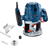
The machine is intended for routing grooves, edges, profiles and elongated holes as well as for copy routing in wood, plastic and light building materials, while resting firmly on the workpiece.
With reduced speed and with appropriate routing bits, non-ferrous alloys can also be machined.
Product Features
The numbering of the product features refers to the illustration of the machine on the graphics page.
1 Adjustment knob for depth-of-cut fine adjustment
2 Scale for depth-of-cut fine adjustment
3 Right handle
4 Depth stop
5 Clamping lever for depth-of-cut coarse adjustment
6 Scale for coarse adjustment of depth-of-cut
7 Adjustment knob for coarse adjustment of depth-of-cut
8 Step buffer
9 Spindle lock button
10 Wing bolt for guide rods of parallel guide (2x)^*
11 Tightening nut with collet
12 Guide plate
13 Dust boot
14 Base plate
15 Left handle
16 Release lever
17 Thumbwheel for speed preselection
18 Lock-on button for On/Off switch
19 On/Off switch
20 Lock for release lever
21 Open-end spanner, size 24mm^
22 Router bit
23 Extraction hose ( 35mm)^
24 Extraction adapter
25 Wing bolt for extraction adapter (2x)^
26 Parallel guide
27 Guide rod for parallel guide (2x)^
28 Wing bolt for fine adjustment of parallel guide (2x)^
29 Wing bolt for coarse adjustment of parallel guide (2x)^
30 Fine-adjustment knob for parallel guide
31 Edge guide for parallel guide
32 Extraction adapter for parallel guide
33 Router compass/guide-rail adapter*
34 Router compass handle
35 Wing bolt for coarse adjustment of router compass (2x)^
36 Wing bolt for fine adjustment of router compass (1x)
37 Fine-adjustment knob for router compass
38 Centring screw
39 Base spacer (included in the "router compass" set)
40 Guide rail
41 Guide bushing adapter
42 Fastening screw for guide bushing adapter (2x)
43 Release lever for guide bushing adapter
44 Guide bushing
45 Fastening screw for guide plate (4x)
46 Centring pin
The accessories illustrated or described are not included as standard delivery.
Technical Data
| Plunge router GOF 2000 CE | ||
| Professional | ||
| Article number | 3 601 F49 ... | |
| Rated power input | W 2000 | |
| No-load speed | min-1 | 8000 - 21000 |
| Speed preselection | ||
| Constant electronic control | ||
| Connection for dust extraction | ||
| Tool holder | mm inch | |
| Plunge depth | mm 65 | |
| Weight according to EPTA-Procedure 01/2003 | kg 6.0 | |
Protection class
回/II
The values given are valid for nominal voltages [U] of 230/240 V. For lower voltage and models for specific countries, these values can vary.
Please observe the article number on the type plate of your machine. The trade names of the individual machines may vary.
Noise/Vibration Information
Measured values determined according to EN 60745 (chip board).
Typically the A-weighted noise levels of the product are: Sound pressure level 89 dB(A); Sound power level 100 dB(A). Uncertainty K = 3 dB.
Wear hearing protection!
Vibration total values (triax vector sum) determined according to EN 60745: Vibration emission value a_h = 5.0m / s , Uncertainty K = 1.5m / s^2 .
The vibration emission level given in this information sheet has been measured in accordance with a standardised test given in EN 60745 and may be used to compare one tool with another. It may be used for a preliminary assessment of exposure.

22 | English
The declared vibration emission level represents the main applications of the tool. However if the tool is used for different applications, with different accessories or poorly maintained, the vibration emission may differ. This may significantly increase the exposure level over the total working period.
An estimation of the level of exposure to vibration should also take into account the times when the tool is switched off or when it is running but not actually doing the job. This may significantly reduce the exposure level over the total working period.
Identify additional safety measures to protect the operator from the effects of vibration such as: maintain the tool and the accessories, keep the hands warm, organisation of work patterns.
Declaration of Conformity C
We declare under our sole responsibility that the product described under "Technical Data" is in conformity with the following standards or standardization documents: EN 60745 according to the provisions of the directives 2004/108/EC, 98/37/EC (until 28 Dec 2009), 2006/42/EC (from 29 Dec 2009).
Technical file at: Robert Bosch GmbH, PT/ESC, D-70745 Leinfelden-Echterdingen
Dr. Egbert Schneider
Dr. Eckerhard Strötgen
Senior Vice President
Head of Product
Engineering
Certification
Paa
Robert Bosch GmbH, Power Tools Division D-70745 Leinfelden-Echterdingen 21.07.2008
Assembly
Inserting a Router Bit (see figure A)
Before any work on the machine itself, pull the mains plug.
It is recommended to wear protective gloves when inserting or replacing router bits.
Depending on the application, router bits are available in the most different designs and qualities.
Router bits made of high speed steel (HSS) are suitable for the machining of soft materials, e.g. softwood and plastic.
Carbide tipped router bits (HM) are particularly suitable for hard and abrasive materials, e. g. hardwood and aluminium.
Original router bits from the extensive Bosch accessories program are available at your specialist shop.
Only use clean router bits that are in perfect condition.
- Press and hold the spindle lock button 9 (0). If required, turn the spindle by hand until the lock engages.
Actuate the spindle lock button 9 only when at a standstill. - Loosen the tightening nut 11 with the open-end spanner 21 (size 24 mm) by turning in anticlockwise direction (②).
- Insert the router bit into the collet. The shank of the router bit must be immersed at least 20mm into the collet.
- Tighten the tightening nut 11 with the open-end spanner 21 (size 24 mm) by turning in clockwise direction. Release the spindle lock button 9.
Do not insert a router bit with a diameter larger than 50~mm when the guide bushing is not mounted. Such router bits do not fit through the base plate.
Do not tighten the tightening nut of the collet without a router bit inserted. Otherwise the collet can be damaged.


Dust/Chip Extraction (see figure B)
Dusts from materials such as lead-containing coatings, some wood types, minerals and metal can be harmful to one's health. Touching or breathing-in the dusts can cause allergic reactions and/or lead to respiratory infections of the user or bystanders.
Certain dusts, such as oak or beech dust, are considered as carcinogenic, especially in connection with wood-treatment additives (chromate, wood preservative). Materials containing asbestos may only be worked by specialists.
- Use dust extraction whenever possible.
- Provide for good ventilation of the working place.
- It is recommended to wear a P2 filter-class respirator.
Observe the relevant regulations in your country for the materials to be worked.
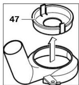
Mounting the Extraction Adapter
Before mounting the extraction adapter 24, bring the machine in the upper starting position by actuating the release lever 16.
Insert the extraction adapter 24, turn the extraction adapter 24 clockwise to the stop until this can be felt to engage (bayonet catch), and fasten it with wing bolt 25.
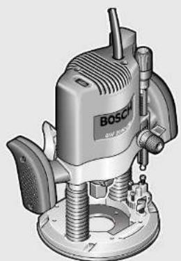
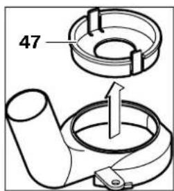
Note: For router bit diameters larger than 30mm the insert 47 must be removed from the extraction adapter 24 by pressing on the clamping shackles.
Connecting the Dust Extraction
Insert an extraction hose ( 35mm) 23 (accessory) into the mounted extraction adapter. Connect the extraction hose 23 to a vacuum cleaner (accessory).
The machine can be plugged directly into the receptacle of a Bosch all-purpose vacuum cleaner with remote starting control. The vacuum cleaner starts automatically when the machine is switched on.
The vacuum cleaner must be suitable for the material being worked.
When vacuuming dry dust that is especially detrimental to health or carcinogenic, use a special vacuum cleaner.
Operation
Starting Operation
Observe correct mains voltage! The voltage of the power source must agree with the voltage specified on the nameplate of the machine. Power tools marked with 230V can also be operated with 220V .
Preselecting the Speed
The required speed can be preselected with the thumbwheel 17 (also while running).
1-2 low speed
3-4 medium speed
5-6 high speed
The values shown in the chart are standard values. The necessary speed depends on the material and the operating conditions, and can be determined by practical testing.
24 | English
| Material Router bit di-ameter (mm) | Thumb-wheel 17 | |
| Hardwood (Beech) | 4-10 | 5-6 |
| 12-20 | 3-4 | |
| 22-40 | 1-2 | |
| Softwood (Pine) | 4-10 | 5-6 |
| 12-20 | 3-6 | |
| 22-40 | 1-3 | |
| Particle Board 4-10 | 3-6 | |
| 12-20 | 2-4 | |
| 22-40 | 1-3 | |
| Plastics | 4-15 | 2-3 |
| 16-40 | 1-2 | |
| Aluminium | 4-15 | 1-2 |
| 16-40 | 1 | |
After longer periods of working at low speed, allow the machine to cool down by running it for approx. 3 minutes at maximum speed with no load.
Switching On and Off
Adjust the depth-of-cut before switching on or off; see Section "Adjusting the Depth-of-cut".
To start the machine, press the On/Off switch 19 and keep it pressed.
To lock the pressed On/Off switch 19, press the lock-on button 18.
To switch off the machine, release the On/Off switch 19 or when it is locked with the lock-on button 18, briefly press the On/Off switch 19 and then release it.
Constant Electronic Control
Constant electronic control holds the speed constant at no-load and under load, and ensures uniform working performance.
Adjusting the Depth-of-cut
The adjustment of the depth-of-cut may only be carried out when the router is switched off.
For coarse adjustment of the depth-of-cut, proceed as follows:
- Place the machine with the router bit mounted on the workpiece to be machined.
- Set the scale for fine adjustment 2 to "0".
- Set the step buffer 8 to the lowest position; the step buffer engages noticeably.
- Loosen the clamping lever for depth-of-cut coarse adjustment 5 by turning in counterclockwise direction so that the depth stop 4 can move freely and faces against the step buffer 8.
- Push the release lever 16 downward and slowly lower the plunge router until the router bit 22 touches the surface of the workpiece. Let go of the release lever 16 again to lock this plunging depth.
- Set the scale for coarse adjustment of the depth-of-cut 6 to "0".
- Adjust the required depth-of-cut by turning the adjustment knob for coarse adjustment 7 and reading the scale 6. Pay attention not to readjust the rotatable scale 6.
Lock the clamping lever for depth-of-cut coarse adjustment 5 by turning in clockwise direction and slide the router upward.
For deep cuts, it is recommended to carry out several cuts, each with little material removal. By using the step buffer 8, the cutting process can be divided into several steps. For this, adjust the desired depth-of-cut with the lowest step of the step buffer and select the higher steps first for the initial cuts. The clearance of the steps can be changed by screwing the adjusting screws further in or out.
After a trial cut, the depth-of-cut can be set exactly to the desired measure by turning the adjustment knob 1; turn in clockwise direction to increase the cutting depth and in anticlockwise direction to decrease the cutting depth. The scale 2 can be used for guidance. One full turn corresponds with a setting range of 2.0mm ; a graduation mark on the top edge of the scale 2
corresponds with a 0.1mm change of the setting range. The maximum setting range is ± 8mm .
Example: The desired depth-of-cut is to be 10.0mm ; the trial cut resulted in a cutting depth of 9.6mm .
- Lift up the router and place e. g. a piece of scrap wood under the guide plate 12 so that the router bit 22 cannot touch the workpiece when lowering it. Push the release lever 16 down and slowly lower the plunge router until the depth stop 4 faces on the step buffer 8.
Turn scale 2 to "0" and release the clamping lever for depth-of-cut coarse adjustment 5 by turning anticlockwise.
Turn the adjustment knob for coarse adjustment of depth-of-cut 7 by 0.4mm / 4 scale marks (difference from nominal to actual value) in clockwise direction and lock the clamping lever for depth-of-cut coarse adjustment 5 also by turning in clockwise direction. - Check the selected depth-of-cut by carrying out another trial cut.
Working Advice
Protect router bits against shock and impact.
Direction of Feed and Routing Process (see figure C)
The routing process must always be carried out against the rotation direction of the router bit 22 (up-cutting motion). When routing in the direction with the rotation of the router (down-cutting), the machine can break loose, eliminating control by the user.
- Adjust the required depth-of-cut; see Section "Adjusting the Depth-of-cut".
- Place the machine with the router bit mounted on the workpiece to be machined and switch the power tool on.
- Push the release lever 16 down and slowly lower the plunge router until the adjusted depth-of-cut is reached. Let go of the release lever 16 again to lock this cutting depth.
- Carry out the routing process applying uniform feed.
- After finishing the cutting process, guide the plunge router upward again to the uppermost position.
- Switch the power tool off.
Routing with Auxiliary Guide (see figure D)
For working large workpieces, e. g. when routing grooves, a board or wood strip can be fastened to the workpiece as an auxiliary guide alongside which the router can be guided. Guide the router with the flattened side of the guide plate along the auxiliary guide.
Shaping or Molding Applications
For shaping or molding applications without the use of a parallel guide, the router bit must be equipped with a pilot or a ball bearing.
- Guide the switched on power tool from the side toward the workpiece until the pilot or the ball bearing of the router bit faces against the workpiece edge to be machined.
- Guide the power tool alongside the workpiece edge with both hands, paying attention that the router is positioned rectangular. Too much pressure can damage the edge of the workpiece.
Routing with Parallel Guide (see figure E)
Slide the parallel guide 26 with the guide rods 27 into the base plate 14 and tighten as required with the wing bolts 10. Additionally, the parallel guide can be adjusted lengthwise with the wing bolts 28 and 29.
Fine adjustment of the length is possible with the fine-adjustment knob 30 after loosening both wing bolts 28. One revolution corresponds with a setting range of 2.0mm . One graduation mark on the fine-adjustment knob 30 changes the setting range by 0.1mm .
The effective contact surface of the parallel guide can be adjusted with the edge guide 31. Guide the switched on power tool with uniform feed and lateral pressure on the parallel guide alongside the workpiece edge.

26 | English
When routing with the parallel guide 26, the dust/chip extraction should take place via the special extraction adapter for the parallel guide 32. The extraction adapter 24 can remain mounted.
Routing with the Router Compass (see figure F)
The router compass/guide-rail adapter 33 can be used for circular routing jobs. Mount the router compass as shown in the figure.
Screw the centring screw 38 into the thread on the router compass. Insert the point of the centring screw into the centre of the circular arc to be routed, paying attention that point of the screw engages into the workpiece surface.
Coarsely adjust the required radius by moving the router compass and tighten the wing bolts 35 and 36.
The length can be fine adjusted with the fine-adjustment knob 37 after loosening the wing bolt 36. One revolution corresponds with a setting range of 2.0mm . One graduation mark on the fine-adjustment knob 37 changes the setting range by 0.1mm .
Guide the switched on power tool over the workpiece with the right handle 1 and the router compass handle 34.
Routing with Guide Rail (see figure G)
Straight routing cuts can be carried out with help of the guide rail 40.
The base spacer 39 must be mounted in order to compensate the height difference.
Mount the router compass/guide-rail adapter 33 as shown in the figure.
Fasten the guide rail 40 to the workpiece with suitable clamping devices, e. g. screw clamps. Place the machine with the guide-rail adapter 33 mounted onto the guide rail.
Routing with Guide Bushing (see figures H-L)
The guide bushing 44 enables template and pattern routing on workpieces.
In order to use the guide bushing 44, the guide bushing adapter 41 must be inserted into the guide plate 12 first.
Place the guide bushing adapter 41 from above onto the guide plate 12 and tighten it firmly with the 2 fastening screws 42. Pay attention that the release lever for the guide bushing adapter 43 is freely movable.
Choose a suitable guide bushing, depending on the thickness of the template or the pattern. Because of the projecting height of the guide bushing, the template must have a minimum thickness of 8mm .
Actuate the release lever 43 and insert the guide bushing 44 from below into the guide bushing adapter 41. Ensure that the encoding keys clearly engage in the grooves of the guide bushing.
- Select a router bit with a diameter smaller than the interior diameter of the guide bushing.
To ensure that the distance from router bit centre and guide bushing edge is uniform, the guide bushing and the guide plate can be adjusted to each other, if required.
- Push the release lever 16 down and guide the router to the stop in the direction of the base plate 14. Let go of the release lever 16 again, in order to lock this plunging depth.
- Loosen the fastening screws 45 by approx. 2 - 3 turns so that the guide plate 12 can be moved freely.
- Insert the centring pin 46 into the tool holder as shown in the figure. Hand-tighten the tightening nut so that the centring pin can still be moved freely.
Align the centring pin 46 and the guide bushing 44 to each other by slightly moving the guide plate 12. - Tighten the fastening screws 45.
- Remove the centring pin 46 from the tool holder.
- Push the release lever 16 and guide the plunge router to the uppermost position.
For routing with the guide bushing 44 proceed as follows:
- Guide the switched on power tool with the guide bushing toward the template.


Push the release lever 16 down and slowly lower the plunge router until the adjusted depth-of-cut is reached. Let go of the release lever 16 again to lock this cutting depth.
- Guide the switched on power tool with the protruding guide bushing alongside the template applying lateral pressure.
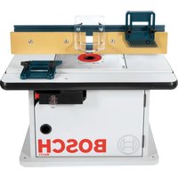
Operation with RouterTable(Accessory)
The GOF 2000 CE is compatible with several router tables available on the accessories market. To ensure safe mounting and usage as intended for the GOF 2000 CE with a router table, it is absolutely necessary that you:
make sure that the selected router table is compatible with the GOF 2000 CE (please observe the information of the router table manufacturer)
follow the mounting and operating instructions of the router table manufacturer
follow the safety warnings of the router table manufacturer and all safety warnings of the GOF 2000 CE in these operating instructions.
Bosch shall not assume any liability whatsoever for injuries and damage that can occur caused by use of the GOF 2000 CE with a router table other than intended for.
Maintenance and Service
Maintenance and Cleaning
Before any work on the machine itself, pull the mains plug.
For safe and proper working, always keep the machine and ventilation slots clean.
In extreme working conditions, conductive dust can accumulate in the interior of the machine when working with metal. The protective insulation of the machine can be degraded. The use of a stationary extraction system is recommended in such cases as well as frequently blowing out the ventilation slots and installing a residual current device (RCD).
If the machine should fail despite the care taken in manufacturing and testing procedures, repair should be carried out by an after-sales service centre for Bosch power tools.
In all correspondence and spare parts order, please always include the 10-digit article number given on the type plate of the machine.
WARNING! Important instructions for connecting a new 3-pin plug to the 2-wire cable.
The wires in the cable are coloured according to the following code:
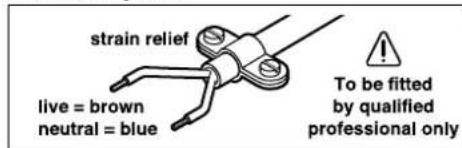
Do not connect the blue or brown wire to the earth terminal of the plug.
Important: If for any reason the moulded plug is removed from the cable of this power tool, it must be disposed of safely.
After-sales Service and Customer Assistance
Our after-sales service responds to your questions concerning maintenance and repair of your product as well as spare parts. Exploded views and information on spare parts can also be found under:
www.bosch-pt.com
Our customer consultants answer your questions concerning best buy, application and adjustment of products and accessories.
Great Britain
Robert Bosch Ltd. (B.S.C.)
P.O.Box 98
Broadwater Park
North Orbital Road
Denham
Uxbridge
UB95HJ
Tel. Service: +44 (0844) 736 0109
Fax: +44 (0844) 736 0146
Australia, New Zealand and Pacific Islands
Robert Bosch Australia Pty. Ltd.
Power Tools
Locked Bag 66
Clayton South VIC 3169
Customer Contact Center
Inside Australia:
Phone: +61 (01300) 307 044
Fax: +61 (01300) 307 045
Inside New Zealand:
Phone:+64 (0800)543 353
Fax: +64 (0800) 428570
Outside AU and NZ:
Phone: +61 (03) 9541 5555
www.bosch.com.au
Disposal
The machine, accessories and packaging should be sorted for environmental-friendly recycling.
Only for EC countries:
Do not dispose of power tools into household waste!
According the European Guideline 2002/96/EC for Waste Electrical
and Electronic Equipment and its implementation into national
right, power tools that are no longer usable must be collected separately and disposed of in an environmentally correct manner.
Subject to change without notice.
Francais | 29
Dr. Egbert Schneider Dr. Eckerhard Strötgen Senior Vice President Head of Product Engineering Certification

Robert Bosch GmbH, Power Tools Division D-70745 Leinfelden-Echterdingen 21.07.2008
34 | Français
Montage
Sous reserve de modifications.
Senior Vice President
Engineering
Dr. Eckerhard Strötgen
Head of Product
Certification
Paa.
Robert Bosch GmbH, Power Tools Division
D-70745 Leinfelden-Echterdingen
21.07.2008


Montaje
Senior Vice President
Head of Product
Engineering
Certification

Robert Bosch GmbH, Power Tools Division D-70745 Leinfelden-Echterdingen 21.07.2008
58 | Português
Montagem
Dr. Egbert Schneider Dr. Eckerhard Strotgen Senior Vice President Head of Product Engineering Certification

Robert Bosch GmbH, Power Tools Division D-70745 Leinfelden-Echterdingen 21.07.2008
70 Italiano
Montaggio
Dr. Egbert Schneider Senior Vice President Engineering
Dr. Eckerhard Strötgen
Head of Product
Certification
Paa.
Robert Bosch GmbH, Power Tools Division
D-70745 Leinfelden-Echterdingen
21.07.2008
82 | Netherlands
Montage
Afzuigadapter monteren
d) Brug违法犯罪.
e beleged to be a legal or official law enforcement activity, including the following:
- the use of force against the public, including the use of force against the police, including the use of force against the armed forces, including the use of force against civilians, including the use of force against civilians, including the use of force against civilians, including the use of force against civilians, including the use of force against civilians, including the use of force against civilians, including the use of force against civilians, including the use of force against civilians, including the use of force against civilians, including the use of force against civilians, including the use of force against civilians, including the use of force against civilians, including the use of force against civilians, including the
e) Hvis el-vaerktojet benytes i det fri, ma der kun benytes en forlaengerleding, der er egnet til udendors brug. Brug af forlaengerleding til udendors brug ned-sætter risikoen for elektrisk stød.
f) Hvis det ikke kan undgås at bruge el-verktojet i fugtige omgivelser, skal der bruges et HFI-relae. Brug af et HFI-relae reducencer risikoen for at fæ elektrisk stød.
Dr. Egbert Schneider Dr. Eckerhard Strotgen Senior Vice President Head of Product Engineering Certification
ppaaee i.v.
Robert Bosch GmbH, Power Tools Division D-70745 Leinfelden-Echterdingen 21.07.2008
Montering
Bosch Service Center
Telegrafvej 3
2750 Ballerup
Tel. Service Center: +45 (4489) 8855
Fax:+45(4489)8755
E-Mail: vaerktoej@dk.bosch.com
Bortskaffelse
Dr. Egbert Schneider Senior Vice President Engineering
Dr. Eckerhard Strötgen
Head of Product Certification
Paa. Mua i.v. Nauogcu
Robert Bosch GmbH, Power Tools Division D-70745 Leinfelden-Echterdingen 21.07.2008
Montage
Bosch Service Center
Telegrafvej 3
2750 Ballerup
Danmark
Tel.: +46 (020) 41 44 55
Fax: +46 (011) 187691
Avfallshantering
Dr. Egbert Schneider Senior Vice President Engineering
Dr. Eckerhard Strötgen
Head of Product Certification
Paa. Mua i.v. Nauogcu
Robert Bosch GmbH, Power Tools Division D-70745 Leinfelden-Echterdingen 21.07.2008
Montering
Dr. Egbert Schneider
Dr. Eckerhard Strötgen
Senior Vice President
Head of Product
Engineering
Certification
ppaaee i.v. nuo ycu
Robert Bosch GmbH, Power Tools Division D-70745 Leinfelden-Echterdingen 21.07.2008
Asennus
Dr. Egbert Schneider Dr. Eckerhard Strotgen Senior Vice President Head of Product Engineering Certification

Robert Bosch GmbH, Power Tools Division D-70745 Leinfelden-Echterdingen 21.07.2008
EuvaepoLoynon
Tonoetnon tou epyaLeiou pefzapiauotc (Bene eikova A)
ByaTeTo pic ano Tny npia npiv ano onoiabnote epyaia oTo nAektpko epyaello.
2acoubetaououe va opate npoatauteutika yavta otav tonotheetire n aalacete to epyalelo ppeapiatoc.
Diarihevtai epyaiae iapezapiapatoc 0e diapopec ekdooeic kai nolotntc, avaloya pe Tnv ekatoTe xphon.
Epyaieia ppeapopatoc ano taxuaa uwnnc anoboo n elva kataanla via tny katepyaaia paakw uikov, n. x. paakov Eauw knaatikow.
Epyaieia ppeaplaatoc me koueic ano oAkpouetao elai eidiKaTAAANe yia Tny katepyaaia oAknpovk aanoEotikwUAIKW, n.x. oAknpov EuaWv kai alouviou.
Ta yvhoia eApntmuata ppeaplaatoc ano to ektevec npoypauma eApntmuTaw Tc Bosch unopeite va npountheutei ano tv appodio yia oac eoouioobotnevo emnpa.
Na xnpaonoiite mvo apotec kai kathetape c ppezec.
Kateuovan kal diaikaia opepaipatoc (Bene eikova C)
To ppezapia npenei va dieyetya navtoe me popa avtloetn tnc pfopac nepiatpouphc tou epyaleiou ppezapiogatoc 22 (avriotpoyn kivnon).Otv ppezapeTe me tnvi ibia popa (ouyxpvn kivnon) mnopei va oac fepuyei ano ta xepia to nlektpiok epyaello.
-PuOIOTe to emUounTo 3a0oc opezapiauatoC, Bane KepdaIao Ppuoi Iaouc opezapiauatoC
-AkoumnoTo nAeKtpko epyaaleo me ouvapuoloynevo To epyaleio ppezaplaoc enawto uno katepyaia teuxo kal oTeTo nAeKtpko epyaaleo ae leitoupyla.
- Patnote to oxo anoavdaawonc 16 npoc ta katw kai obnynote tnv katheta npeza ayaoia npoc ta katw, mexpi va enituxete to puoiuevo baooc ppezapiaatoc. Apnte nai eueuepo to oxo anoavdaawonc 16, ia va otaepoionoe auto to baoc buoianc.
-△iEayeToΦpezapiaaakwvtacouoio-μopqn nieon.
-MetaTov TepuataoTOU pceaplaatoc oynnoTe Tny kaetn ppeza nai Tepa enayw.
-0eote to nAekptko epyaaleo ektoc aeitoupyiaac.
Dr. Egbert Schneider Senior Vice President Engineering
Dr. Eckerhard Strotgen
Head of Product Certification
Robert Bosch GmbH, Power Tools Division D-70745 Leinfelden-Echterdingen 21.07.2008
Montaj
Frezeucunun takilmasi (Bakiniz: Sekil A)
Bosch San. ve Tic. A.S.
Ahi Evran Cad. No:1 Kat:22
Polaris Plaza
80670 Maslak/Istanbul
Müsteri Danismani: +90 (0212) 335 06 66
Müsteri Servis Hatti: +90 (0212) 335 07 52
Tasfiye
Dr. Egbert Schneider Dr. Eckerhard Strotgen Senior Vice President Head of Product Engineering Certification
ppa. 1
Robert Bosch GmbH, Power Tools Division D-70745 Leinfelden-Echterdingen 21.07.2008
Montaż
System Constant Electronic
Robert Bosch Sp. z o.o.
Dr. Egbert Schneider Dr. Eckerhard Strotgen Senior Vice President Head of Product Engineering Certification
Paa /nau
Robert Bosch GmbH, Power Tools Division D-70745 Leinfelden-Echterdingen 21.07.2008
Montáz
Bosch Service Center PT
K Vapence 1621/16
692 01 Mikulov
Dr. Egbert Schneider Dr. Eckerhard Strotgen Senior Vice President Head of Product Engineering Certification

Robert Bosch GmbH, Power Tools Division D-70745 Leinfelden-Echterdingen 21.07.2008
Montáž
Dr. Egbert Schneider Senior Vice President Engineering
Dr. Eckerhard Strötgen
Head of Product
Certification


Robert Bosch GmbH, Power Tools Division
D-70745 Leinfelden-Echterdingen
21.07.2008
Összeszerelés
*3o6paKeHHbIe HAN OHnCaHHbIe IPNHaAeXHOCTH He BXoADT BCTaHApTHbI KOMTAEKT NOCTABKN.
TexHHueckne daHhbie
3haueHHe 3MnCCNN K0e6aHH a=5,0 M/c², HdoctOBepHOCTb K=1,5M/c².
Yka3aHHbI B HactoHux HNCTpyKunx yPoBeHb Bn6paunu H3Mepeh CTaHdApTN3HPOBaHHbIM B EH 60745 MeTOOM H3MepeHna MoKeT 6blb HcnoB3OBAH DA CpaBHeHNA HcTpyMeHTOB. OH TaKxe PpHroDeH AAR BpeMeHHO OeHKn Harpy3Kn OT Bn6paunu.
PnBBeHnBHy yPoBHeB Bn6paunn PpeCtBaAer OCHOBHbIe BNdbI pa6ToI 3AEKTPoHNCTpyMeHTa.
OdaHko,ecn 3AeKTPoHnCTpyMeHT 6yEt HcnoB-30BaH DA BbIIOAHENH Apyrnx paBoT C pIpmHeHempaOounx IHCTpyMeHTOB, He IpeDyCMOTpeHHbIX N3TOBtAEm,HNTEXHueCKoe 6CAYKBaHHe He 6yEt OTBeuATb IpeAINCAHNM,To yPOBEHB BbPAaun MoKeT OTKAOHrTc.3To MOxET3HaUHTeBHO IOBbICNTb Harpy3Ky OT BbPAaun B TeueHne BCero paBOOer TepNoaDA.
DA ToHOn OuenHK HArpy3Kn OT Bn6paun
DOXHb6bItb UyTeHb TaKke OTpe3KN BpemeHN,B KOTOpBle 3AeKTPoHnCTpyMeHT BbIAIOueH NbBpaaetCnHO DeNCTBnTEbHO He BblIOAnHRe
paObTo.3TO MOKET 3HaUHTeBHO COKpaHTb
Harpy3Ky OT Bn6paun B paCte Ha IIOAHOe
paOoee BPema.
YCTAHOBHTe DToTAAHNTeBHBIE MePb 6e3oTachocTN DA3aunTb OIepaTopo AT Bo3dEChTBn B-6paun, HApnpMe:TexHueckoe ObcayKBaHne 3AEKTPOnHHCTpyMeHTa N paOchN HHCTpyMeHTOB, TEAble pyKn,OpraHn3aun TExHOAnruecknx IPOUeCCOB.


198 | Pycsckn
3aRaBHeHne o COOTBeTCTBHN C
CIOAHOHOTBETCTBEHHOCTBMO3aRABAEM,TOOINCAHHBIBpa3dEe《TEXHNueCKNEdaHHbIE》IPOADKT COOTBETCTBYET HIXKecAEDYIOUIMCTaHApTaHMANHOPMaTHBbIMDOKyMeHTaM:EH60745coTAAcHoTIOAOxEHnAMNpeKTH2004/108/EC,98/37/EC(o28.12.2009),2006/42/EC(HaHHa c 29.12.2009).
TexnueckanokymentauxpaHnty: Robert Bosch GmbH, PT/ESC, D-70745 Leinfelden-Echterdingen
Dr. Egbert Schneider Dr. Eckerhard Strotgen Senior Vice President Head of Product Engineering Certification
Paa /aa /i. Nauy
Robert Bosch GmbH, Power Tools Division D-70745 Leinfelden-Echterdingen 21.07.2008
C6opka
YcTaHOBkaΦpe3bl (cm.pnc.A)
OHaApa6oTIOO6AYKBAHNO HACTPOKe 3AEKTPOHHCTpyMeHTaOTcoeHNHnTe Bnky Uhypa cETN OT WTeNCeABHOI PO3ETKN.
Aa yTaHOBKn mCMeHb fpe3bl peKoMeHdyetc TIOb3ObaTbcr 3aunTHbIMn nepyataKMn.
B 3aBnCmOCTn OT CEAn PpImeHeHH B pAcTOpApaKeHH NMeIOrCa3AUNHbIe NCtOAnHeHH N KaueCTBa Cpe3.
Φe3bI 36bIcTPOpeXyuei CTANIOBIIeHHOI PpOuHcTN PdHa3HaueHbI A8o6pa6OtKN MArKNX MaTePnaAOB, KaT To, MArKoI ApeBeCnHbI n IaCTMaCcbI.
Φe3bCTBepDocnABHbIMnTAACTNHkAMNOC6eHHIOPIRHOHbI DA TBPdIX n a6pa3NBbIXMaTePnaAOB,HaTPmEep,DA TBPdoApeBeCnHbI aAOMHHNA.
OpHnHaBHeIe 3bI n6uHpHoi
IporpaMMblIOCTABKn HnpMb Bosch Bbl
IpoAyuTe y BaWero cneuaHnroBaHnro
IpoaBAua.
PpIMeHnTe TOaBko 6e3yKOpn3HeHHbIe n uNCTble fpe3bl.
HaxMMTe KHOITky 6AOKINPOBKN WITINHDeAEN9 (O) HApEKPHTe ee. PnHADo6HOCTH IOBePHNTE WITINHDeABy pKOJ DO cpaBaTBbAHNA 6AOKINPOBKN.
KHTKY 6AOKNPOBKN WITINHDAA9 HAXMMAITE TObKO B COCTORHN TOKOR.
OTNYCTHTe HAKHHyOraKy11raeYHBIM KAOyOM 24 MM 21, Bpaaeraero IpoTINB YacOBoN CTpeAKN ()
BcTaBBTe 6pe3y B 3aXHHMyu caHry. XBOCTOBHK 6pe3bl DOAnKeH BOHTN B 3aXHHMyu cHaHy, IIO KpaHHei Mepe, Ha 20 MM.
3aTnHHe HaKnHHyo raKy 11 raeHbIM KAOyOM 24 MM 21, BpaIaI erO IIO yacOBO CTpeAke. OTNcHTe KHOITky 6AOKHPOBKN WTHINHDAE9.
He yctaHabHbAte HnKaKne Ppe3bl c dAmetpom CbbIe 50 MM 6e3 KOtHPOBaHbHOr Hb3bl. 3TN Ppe3bl He TPOXoARHTpe3 PAHTy OCHOBaHNA.
HnB KOem CAYae He 3aTARNBaHTe HAKNDHYO rayky 3axHMHOu aHaRr 6e3 fpe3bl. Hnue 3axHMHa YaHra MoXeT 6bItb NOBpeXdeHa.
OTcOC IIbIaH n CTpyKKn (cm. pnc. B)
IIbIb MaTePnaIOB, KaK To, KpaCKn C COePkaHHeM CBHHua, HeKOToBbIX CopTOB DpeBeCNbI, MNHepaOB H MetaAa, MoXeT 6blb BpeHON dA 3AOPOBB. IpnKoCHOBeHne K bIIIN N IOIaHaHne TbIaBbXaTebHbIe PNYMOxET BblBaTb AAneprNueeCKne peAKuHN /nn 3a6OBeBAHn ABxATEbHbIX PyTe OPeTaOp aHn HaxOaJUeOcR B6AN3N IepcoHaN. ONpeDeAEHbIe Bnbl BtIaN, KaK To, Ay6a N 6yKa, CHTaIOTc KaHcEporeHbIMN, OCOeHN COBmecTHC O pncAckAM N DA Opa6OTKN ApeBeCnbl). MaTePna C COePxaHHeM ac-6bcTa pa3peWaaTcR Opa6aTbBaTb TObko CTeuHaNCTam.
-IO BO3MOXHOCTI INPMHEHTEOTCOC IIbIAN.
- CaeAnTe 3a xopoWe BENTHAAUne.
- PeKOMeHdyeTc IIOb3ObaTbCABdxAteAbHOI 3aunTHoMACKoN CΦnA bTpOM KAcca P2.
Co6AHOaIte DeHCTByUe N BaWey CtpaHe IpeAHCaHNA DA O6paBaTBbAemblX MaTePHaAOB.
YcTaHOBka OTCacbIBaIOUero aAaTepa
Do MOHTaKa aadTepa OTCacbIBaHn 24
TOBePHnte pbUar pa36oKnpOBKn 16 n
yCTaHOBNTe 3AekTpOHnHCTpyMeH B HxCXoADHe
IIOAOKeHne.
BCTaBtE OTCacbIbAoum aadTep 24, IOBepHnTe OTCacbIbAOu m aadTep 24do 3aMeTHoro yTopa HnpaBo (6aHOHehbl 3aTbOP) n 3akpeHnTe erO bapaWkoBbIM BHTOM 25.
YkaaHHe: DnAΦpe3 C dHaMeTpOM Cbblue 30 MM CAeYET BbIHyTB BCTABky 47 N3OTcAbBaIOUero aadITpe 24, Haxab AAD TTOHpBnAHr.
PnncoeHHeHne TbIeOTcoca
HacaHTe 1aHaTcOTcBaHn(035MM)23 (PnHaAExKHOCTn)HaYCTaHOBaeHHb aAaTTep OTCaCbHAHn. CoEHNHTe 1aHaTcOTcBaHn 23C TbIaecOCOM (PnHaAExKHOCTn).
3AeKTPoHHCTPymEt MOKet 6bItb IOaKaHoue HPPMO K WTeTceAbHOI PO3ETKe YHNBePcaAbHOrO TbIEcOCa FHPMb Bosch c yCTPOHCTBOM AHTaHNOHHORo TpCKA. IIIEcOC aBTOMaTHueckn 3aITyckaETcR PtN BkIOueHnn 3AeKTPoHHCTPymEHa.
TbIeocdoXKeH6bIbPnrooEnAorO6pa6aTaBaemoroMATEpHaA.
PpIMeHnTe CteuHaBbI TbIeCoc DAOTcAcblBaHHO Oc06 BpehIX DAn 3doPoBBnIOB TbIa -BO36yDnteJe paka Hn CyXoTbIa.
Pa6ota c nHcTpymeHTOM
BkaioueHne 3aektpoHHctpymehTa
YuHTbIbAte HAnpXeHne cet! HApXeHne NcToHHKa TOKa DOAXHO COOTBeTcBOBaTb DaHHbIM Ha THTOBoTa6AnUKe 3AekTpOHcTpymEHa 230 B MoryT pa6OtaTb TaKHe H pIn HApXeHmB 220 B.
Hactpoinka Hcna o6opotOB
C NOMOsbU yCTaHOBOHOro KOAEChKa 17 Bbl MoXeTe yCTaHOBnTB Heo6xoAMoe YNC0 O6OpOTOB TAKKe I BO BPempa60Tb.
1-2 Hn3Koe YncAo o6oPoTOB
3-4 cpeAhee uncAo 06opoTOB
5-6 BBICOKoe YHCnO O6OpOTOB
PnBHeEHHbIe B Ta6Anue 3HaueHHraBIAOTcOpneHTnpoBOUHbIMN 3HaueHHaMn. HeoXoAMMoE qncAo 6OpOToB 3aBNCt OT MaTePhaHa Ha paox yCObH N MoKeT 6bItb OtpedeAeHo TpakTHueckm FpeepoBaHem.
AAR BKAIOUeHn 3NeKTPoHnCTpyMeHTa HaxaTb Ha BBiKaHOuATEAb 19 N DePKeTaB erO HaxaTbIM.
AaΦHKnpoBaHb BbIKIOyATEe19 BO BKAHOyeHHOM IIOAOKeHH HaKMITE KHTKY ΦHKnpoBaHb 18.
AABBbIKIOOeHHN3AEKTPoHCTpyMeHTa OTYcTHe BbIKIOOHTaeAb 19 HAN, ECAN OH 6bIA 3aΦHKcPOBaH KHOITKOΦHKcPOBaHH 18, HAKMTHe N OTYcTHe BbIKIOOHTaeAb 19.
3AektpoHHa CnCTema cta6HnHaunckopoocTH BpaueHn
3AekTPOHHa CNTema cta6HnHa3auHH BbIePjNBAeT UcAo O6OpOTOB HxOAOCTOM XoHy NIOA Harpy3Ko IOyTH IOCTOARHHbIM N o6ecTeuHBaet paBHOmepyH IOHNBOAnTEAbHOCTb.
YcTaHOBka rAy6HbI ppe3epoBaHHa
YctahOBkyrAy6HbblppeepoBaHHpa3pe7aetcBbIIOAHHTbToBko PnBBiKAHOeHHOM 3AEKTPoHHCTpyMeHTe.
Ipy6yHnactpoKnyIy6HnblΦpe3epoBaHHBbIHOHHTe CLeAyoHm 06pa3OM:
-yctaHOBHTeAeKTPoHnCTpyMeHT C 3aKpeIeHHoHΦpe30Ha IIOAeXaUyO 6pa60Te DeTaA.
- YcTaHOBnTe WkAny ToHKn HAcTpOKn 2 Ha 0
- YctahOBHTe CTyIeHuATbYyTOp 8 Ha camyIO HN3KyoCTyIeHb; CTyIeHuATbYyTOp fHKcpyETcABTomAtueCKn.
OTNYCTHTe 3aXHMHOH pUyar rpy60n HACTPOKn Iy6HbI qpe3epoBaHN5, IOBEPHyEero HAeBO,TAK,yTO6bl ynpO rIy6HbI 4 CBO6oHO OTYCTNaCnHa CTyIeHuTaBn yIop8.
HaxMNTe Ha pblar pa36KnpOBKn 16 BnH3 n MeAeHHo BeAnTe PpeepHyIO MaunHy BnH3, TOKa Ppe3a 22 He KOCHETcT IOBepxHOCTn DeTAA. OTNCTne PbHAR pa36KnpOBKn 16, UTOb 3aΦNKcnpOBaTb 3Ty Iy6NHy TOrpyKeHN.
- YctaHOBnTe Wkany rpy6oHnactpOKN 6 Ha 0
- YctahOBHTe XeLaemyIpy6Hy
pe3epoBAHHBpaHHeHm pyuK rpy60
HaCTPOKNIy6HNbI ppe3epoBAHH7
IPOBepaHACTPOKYIO WkaAe 6.He
CMeuaTe 6OaBwe HAcTPOKY KaAbl6
-3aФнксруte 3axmHnoI pyuar rpy6oB nactpoKn raybnhb fpeepobAHn5, IOBepHyB erO dA 3TOr HAnpaBO, INepeMeCTHTe AKeTPOINHCTpyMeHT HaBepx.
Aa 60bwoI rhybHbI φpe3epoBaHHcAeyet BbIOAHHTb HeckOaBko pa6OHy IPOXoAOB C MeHbWeI ToUHNHO CHNMAeMoro cAoR. C TMOOsbIO CTyHeHATOrO yTnopa 8 IPOuecc φpe3epoBAHH MOxHO pa3DeAANTb Ha HeCKoABoK CTyHeH. AAN 3TOr OYCTaHOBHTe KeLaEmyTO Ry6HHy φpe3epoBAHH C camO HN3KO CTyHeHIO CTyHeHATOrO yTnpA N bblEepHTe Dn TEPBbIX pa6OHy IPOXoAOB CHaHaA BblCOKHe CTyHeH. PacCTOraHHne MekMy CTyHeHm MOxHO H3MeHHTb BpaueHHem HAcTpoeHbIX BnHTOB.
Tocae npo6horo npoxoDa Bbl moxete
BpaueHem IOBOPOTHO pyuKN 1 ToH0
yCTaHOBNb IAY6HNHy Ppe3epOBAHnHa
KeaEMbi pa3Mep; AAN yBeAuHEnraIy6HbI
BpaauTe pykU npOTNB uACOBOB CTpeAKN, AAN
ymeHbUHeHRAy6HbI -IO uACOB CTpeAke.
TPn 3OM WkaAa 2CayXHTAON OPHEHTPOBKn.
OAnH O6pOTo COOTBEcTBye XOyD YCTaHOBN B
2,0 MM, OAnHO DeAEHHe NIO BepxHEmy KpaIO WkaAa
2 COOTBEcTByeH3MeHeHHO XOaYCTaHOBN B
0,1 MM. MAcKHMaaHBn XoA yCTaHOBN
coCTABAHET±8MM.
TIpMep:KemaemraIy6nHaΦpe3epoBaHnAdoXHa 6b1b 10,0 MM, Ipo6hBII IPOXoA BIdaIra6nHy B9,6 MM.
-Пинлднмпгфpe3epHyMaHnHy n
ПОДAOKNTe ПОД ПИNTy COKaBXKeHne,
HATPIMeP,DEpeBHHbIe O6pe3Kn 12,TaK
ЧтOБblФрета22Ри ChYcKe He KacAaCb
ЗагOTOBKN.HaxMNTeHa pblar
pa36oKInpOBKn16 BnH3 H MeAeHHO
ПЕБeДМТeФpe3epHyMaHnHy BnH3,TOKa
уpop rABy6nHbI4He cAET Ha CTyIeHuTaBly
уpop8.
- YcTaHOBHTe 1kaA2 Ha «O» n OTnycTHe 3aKHMHoi pIyar rpy6oH hAcTpoKn rAynHbI pfpeepOBAHn5 BpaueHHem HaeBO.


Pycckn | 201
IIOBepHnTe pyk7 Ha 0,4 MM/4 AeHeHHa (pa3HNu3aHaHHOro H DeHCTBnTeAeHOrO 3NaueHn) IIO YacOBON CTpeAke N 3aTnHnTe 6apaKOBbINHT5.
- PpOBepeTe yctaHOBaeHHyTo rABy6HHy CLEdyUoHM PpO6HbIM PPOXoOM.
yKa3aHHI IO ITPHMHeHnIO
IpeaoxpanTe cpe3y ot ToaKOB yapob.
Happaaenhe ppeepoBaHHn nIpouecc ppeepoBaHHn (cm.pnc.C)
Ppoecc ppeepoBaHHdoJXeH Bcerda PPOBOANTc BO BCTpeHOM HAPpaBaeHH BpaehnHppe3b2 22. PnTOnyTHOM ppeepoBaHH MaHHaA DAppeepoBaHH MOKET 6b1b BBpBAHa OepaTopy H3 pyK.
-YCTAHOBHTeXeIaEmyIOIy6Hy pe3epoBaHn,CM.pa3deA《YCTAHOBKa Iy6HbIppe3epoBaHn》.
-IOCTaBbTe 3eKtpOnHcTpymENT C yctaHOBaeHHoHΦpe30HaIPOdEkaUyIO 6pa6OtKe DeTaBn BkAIOuHTe 3eKtpOnHcTpymENT.
HaXMMTe Ha pbyar pa36AOKpOBKn 16 BnH3 n BeNte PpeepHyo MaunHy MeaENHO BHN3 DO AOCTNXeHHY YCTAHOBAEHHO rYbHbI PpeepOBaHH.OTyCHTe PbUar pa36AOKpOBKn 16,UTobb3aФHKcPOBaT 3Ty yBbHHy TOrpyKeHH.
-BbIIOAHHTeΦpe3epoBaHne c paBHOmePHO IOaueH.
-ПО okOHuaHnI npuecca φpe3epoBaHnI nepeBedeIe φpe3epHyIO MaunHy B BepxHIO I03HIO.
-BbIKAOHTe3AekTPOHcTpymeHT.
Φe3epoBaHne c BCtOMoraTeAhbHbIM yTOpom (cm.pnc.D)
Aor6pa60Kn 6oBunx 3arOToBOK,HaPnHMepe,
AaΦpe3epoBaHHn Ta3OB,Ha 3arOTOBKe MoXHO
3aKpeNTb DocKy Hn PAnHKy B KaueCTBe
BCNOMORAteBHorO yToppa NΦpe3epoBaTB BDOB
3TOrO yToppa. BeAnTeΦpe3epHyO MaunHbI
CIPRAmEHHo CTOpOH TnTb CKOAbXeHHa
BDOAB BCNOMORAteBHorO yToppa.
Φpe3epoBaHne KpOMOK HAN PPOHbHOe Φpe3epoBaHne
PpneepoBaHn KpOMK Hn PPOHnEe
Ppe3a DOxHa 6bTb OchaueHa HnPaBnOe
Uanfo Hn WapNKoTOAunTHNkOM.
-ⅠOaBeaHTe BKAIOueHHbI 3AeKtpoHnCTpyMeHT CO CTOpOHbI K DeTaAN TaK, YTO6bl HAITpaBAJIOUaIaIpa HAI WApNKOTIOOWHTIHKn Fpe3bl YIepCRB I IOaLexaYIO OpbapOKe KpOMKy DeTaAN.
-BeNTe 3AEKTPoHHCTpyMeHT o6eHN pyKaH M BDOA b KPOMKN DeTaAH. CaeNTe PnP 3OM 3a PPRAMOYTOABHBIM PnPAEraHHeM.CANIKOM 60AbwOe yCnHne MoXET IOBpeAnTb KpOMKy DeAATN.
Φe3epoBaHne c npapaAaIbHbIM yIopom (cm.pnc.E)
BCTaBtpe npaaAeBhbl yIop 26 BmecTe C HnPaBAAHOUMN uTahrAmN 27 BnHTy OCHOBAHNA 14 n3akpeNTte ero 6apawKBbIMn BNHTAMN 10 corAacHo Tpe6yeMomy pa3mepy.C TOMOuHb 6apawKOBbIX BNHTOB 28 n 29 Bbl MOXeTe AOIOAHTHe ABHO hAcTPOHTb TapaAeBhl yIop nO DAHNHe.
Bpaauoesepyko30BblMOKeTe,OTNCTNB 6apaKOBbIe BHTb28,BblIOAHHTb TOHKyHO HAcTPOkyAHHbl.IPi3TOM OAnH O6OpOT COOTBeCTByET XOyUcTaHOBKn B2,0MM,OHO AeHeHa Bpaauoesepyke30 COOTBeCTByET XOy UcTaHOBKn B0,1 MM.
C NOMOJIyUyTOPHOI PAHKN 31 Bb MoKeTe I3MeHNb 3cpeKTHBHyO paOuyIO PIAUaIb TapaAeMbHOYTOpa.
BeNTe BKAUoeHHbI 3AeKTPoHnCTpyMeHT C paBHomePHOIPOaueH N60KObIM DaBHeHEm B CTOpOHy IpaAaEaHOrO yTopa BDoA b KpOMKn DeTaH.
Pn ppeepoBaHH n npaaMaBbHm yTOpom 26
OTCOC TbAH/CTpyKKD OAnKeH OcyeCTBArTBcra
uepe3 CteHaBbHn aAaTtep 32.
OtcabBaOuH aadTep 24 MoKet 6bTb OCTaBAeH Ha MaWHe.


202 | Pycsckn
Φe3epoBaHnE c uHpKyAeM (cM. pnc. F)
AaΦpeepoBaHnI IO KpyrBbMOxTe BOCIOAB3OBaTbCnHPKyAm/aadITepOM HappaBIAOuEe uHHb 33.YcTaHOBHTe npkkyb ΦpeepoBaHnI corlacho pucHyk.
BbHTte BnHT ceHtpnoBaHna 38 Bpe36y
Φpe3epoBaIbHorO uKpyI. IocTaBte OCTPne
BHTa B CEHTp IOAExKaIe Φpe3epoBaHIO
dyr OkpyxHOCTn n CLENTe Pn 30m 3a TEM,
TTo6bl OcTpe BnTA BxOAno B IOBepXHOCTb
MaTePnHa.
YCTAHOBHTe rpy60 paAnyc CMeUeHEm cIpyKyA H 3aTAHHTe 6apawkoBbE BnHTb35n36.
BpaaHoueCpUKo37BbMoKeTe,OTNcTb6baaKOBbBnHT36,BbIOAHNbTOHKyoHAcTPOKYANHBI.PIN3OMOAnHO6OpOTCOOBETCTByETXOyCTaHOBKNB2,OmODeAEHeHHeHaBpaauoEeCpyKe37COOBETCTByETXOyCTaHOBKNB0,1MM.
BeNTe BkHOueHHb 3AekTPOHnCTpyMeHT C npBOI pyKoRTKO I n pKoRTKO AAR uNPkyA fpe3epoBaHHa 34 No dTaAH.
Φe3epoBaHne c HnpaBAnOuSei uHHO (cm.pnc.G)
C HnpaBAAIOe WnHO40 Bb MoKTe BbIOnAHTb PpMaHHeHbIpeBaOpue Oepaun.
A BbipBnBaHnPa3HnBIO BbICTe CaeyET yCTaHOBTb IPOCTABOCHYIOIANTY 39.
YCTaHOBHTe UINPKyIb FpeepoBaHN/aadTep HAnpabAHOUe WInHb corAcho pncyHKy 33.
3aKpeHHe HApBaAHOUO uHy 40 C TOMOuBIO
TDOxOAnX 3aKHMhBix yCTPOINCTB,HaIPMep,
CTpy6uHH Ha DeTaAH. IocTaBBte
3AEKTPOINHCTpyMeHT C yCTaHOBAeHHbIM
aAdITePOM HApBaAHOUe uNHBi 33 Ha
HaHPaBAHOUO uHNHy.
Φe3epoBaHnC KOINpOBAbHOH rHb30n (cm.pnc.H-L)
C NOMOJIbHO KOINPOBaHOB Hb3bl 44 Bbl MOKeTe IpepeHocHTb KOHTpybI C O6pa3IOB HnH Ma6AOHOB Ha DeTaAb.
AIIIINHNNKONHOBbHOHrAB3b4 CnauaAoXeH 6bITb yCTaHOBaeH aAnTep KOHOBAbHOH rAB3b4 41 B PNTy CKoABxHeHH 12.
BCTaBbTe aadTep KOINPOBaHOB Hb3b41 CBepxBy TNTy CkOABKeHHN 12 N 3aKpeNTe ero ABym KpeIeXhBMn BHTAMN 42. CaeIte Ipn 3OM 3a TEM, YTO6bl pbuH par pa36AOKnPOBKn aadTepa KOINPOBaHOB Hb3b4 43 CBO6oHO IOBOPaYBaCAr.
Bb6epHe TIOAOAUYO KOHPOBaHyO rHb3y B COOTBeCTBHN C TOAUHHO WbAHOHa HnOBpa3ua. H-3a BbCTTyIaOpEe BbICOTbI KOHPOBaHOBrHb3bI TOUHHa WbAHOHa DOxHA 6bITb He MeHe8 MM.
3aeneCTByTe pbyar pa36loKpOBKn 43 n BCTaBbTe KOHTPOBaAHyHO rAa3y 44 CHN3y B aAaTep KOHTPOBaAHoH rAa3b41. Pn 3tOM KyaauKN KoAnPOBaHH DoAxAHbI C He6oAusbm ycHHeM fHKCHPOBaTBcB N a3ax KOHTPOBaAHoH rAa3b4.
DnAmETpΦpe3bldoAnKeH6bITbMeHbIe BHYTpEnerHOaMaTePaKOTnPoBaBHoH IHa3bl.
AoeceHnOHaKOBOrpaCtOHnOT
UeHTpaΦe3bldoKpaKoTnPOBaHbHOrHA3bl
IOcAeHnI NNTaCKoLbXeHn,PIH
HaO6HoCTn,MOYt 6bITbcENTpnpoBaHbI IO
OTHOWeHHNOdpyKdpyry.
Haxmte Ha pbyar pa36oKnpoBkn 16 n OtycTHe pfpeepHy MaunHy do ynpa B HATpaBAEHNI PAHTb OCHOBaHHN 14. OTyCTHe pbyar pa36oKnpoBkn 16,TO6bl 3aФNKpOBaBt 3Ty rAByHNY TOrpyxehnH.
OTnyctnte KpeTeXHbE BnHTbI 45 np6A. Ha 2-3 o6oPota, taK, yTo6bl NdoWba 12 CBO6OHO Tepemeuaaacb.
- YctahOBHTe OpiBky ueHtpnpoBaHH 46 B uAhry paOohero HnCtpymenta.3aTnHTe pyKoHaknAHyro raKy TaK, Yo6bl OpiBaKa ueHtpnpoBaHH eIe BpaAaaacb.
BbIePeTe OITpaBky CEHTpnpoBaHn46 n KOIIpOBAaBHyO rA3y 44 C IOMOJIbHO HeoIbWoO CMeueHHN IANTbIO OCHOBAHn12 IO OTHOWeHHIO ApyKApry.
-3aTnHTe KpeTExKhBie BHTbl 45.
- YdaHte onpaBky ueHTpnpoBaHH 46 n3 uahn paOoery HhCTpyMeHTa.


Pycckn | 203
HaxMMTe Ha pblur pa36oKnpoBKn 16 n BbIBeAnTe fpeepHyu MaunHy B BepxHee noAOXeHne.
Φpe3epoBaHnE y3aOM KOINHOBaHn4 44 BbIIOAHHTe CaeDyUOuMm O6pa3OM:
-ⅠOaBcIeBkAIOueHHb3AeKTPoHnCTpyMeHT C KOIIPOBaABHOI Hb30I K Waa6AoHy.
Haxmte Ha pbyar pa36oknpOBKn 16 Bn3 n BeNTe fpe3epHyo MaunHy MeaehHo Bn3doOCTnxKeHNy yctahOBaehHO rhybblfpe3epoBaHH. OTnyte paBpar pa36oknpOBKn 16, T06bl 3aФNKcnpoBaTb 3ty rAByhNy TOrpyKeHN.
-BeInTe 3eKTPoHHCTpyMeHT C BbICTyTAIOUeN KOINPOBaAHOH TnAB3Oc B6OKOBIM YCNAHEBDOA b6A0Ha.
Pa6ota cΦpe3epoBaAaBbHbIM CToAOM (PnHaAdEeXHoCTH)
MaunHa GOF 2000 CE coBmecTnMa co MHOrHMn FpeepoBaHbIMn CToAMn, PpeAraEmbIMn Ha pbIHKe PnHaAeXHoCTe. Aa HAdExHoro MOHTaKa MaunHbGOF 2000 CE c FpeepoBaHbIM CToAOM N KcIpyaTuIN CoACHO Ha3NaueHIO 683ateBHO Heo6xOIMO:
-06ecneuHb COBMeCTHMocTb Bbl6paHHORo
Φpe3epoBaIbHOro cToa C MaunHOJ
GOF 2000 CE (yHTHe DaHHBe
n3rTOBHTeA Φpe3epoBaIbHOro cToa)
-ya3aHnIIOMOHTaxyN06cLyXnBAHNIO 3rTOBNTeAΦpe3epoBaNbHO CToLa
-BBIOHARb BCE yka3aHHI IO 6e0nacHOCTn Tpyda H3rOBoHTeA Ipe3epoBaIbHorO CTOna N BCE yka3aHHI IO 6e0nacHOCTn H3 HaCToIeRO pykoBOdCTBa IIO 3KcIyatauIN GOF2000CE.
Bosch He OTBeaet 3a TpaBMbl IOBpeXeHn HmYueCTBa, KOtOpbE MOryT BO3HNKHyTbIpiH HeIpaBnAbHom IpImMeHeHH GOF 2000 CE cΦpe3epoBaHbIM CToAOM.
Texo6cayxmbaHne n cepBnC
Texo6cayXnBaHne n ouhctka
Do haayaa pa60TIO 6cayxHBaHnIO HA-CTPOKe 3eKTPoHNCTpyMeHTA OTOeHN-HaTe BNAky hHypa cETN OT WTeNCEAbHOI PO3eTK.
Aa oecteehna kaectBeHHo H 6e3oTacHOn pa60tbl CAeYet IOCTOHHo COePkaTb 3AEKTPONHCTpyMeHT N BEHTNAUHOHbI Tnpope3N B uHCTOTE.
Pnpe3BbUaHbIX 3KCTAYatauHOHHbIX yCIOBHX PnO6paOte MeTaALOB BHYTPN 3AEKTPOHCTPymeHTA BO3MOXHO OCAXDEHHe 3AEKTPoTPOBODIeIbIaN.3TO MOxET CHABHO IOBAHHTb Ha 3aunTHyIO H3OARUHO 3AEKTPoHNCTpymeHTB B TaKHX CAYyax PEkOMeHdyETc HcNOb3OBaTB cTAUHOHPHy OTCacbIBaHOUY YoCTAHOBky, qACTO IPOyDAByB BEHTHAUNHOHBE WAnCbI H BKAOHTb TEpeA 3AEKTPoHNCTpymeHTOM ABTomAT 3aunTbI OT KOKOB TOBpeXdEHNA
Ecn3AekTponHCTpyMeHT,HeCMOTpaHaTtataBHBie MeTOaBI N3rTOBAAeHN HNCbTAHH, BbIaETn3 CTPoA,TO pEMOHT CAEyET PON3BOAnTBCHAMn ABTopN30BaHHo CEPBCHOH MaTePCKO DA3AekTPOHnCTpyMeHTOBnPmB Bosch.
TokaIycta, BO BceX 3apocax H 3aka3ax 3anacteY o63atebHO yka3bibaTe 10-3naHbI TOBapHbI Homep ITO TnTOBOI Tabauke 3AektpoHHCTpymEnTa.
CepBnchoe 06cayxHBaHne KOHCyIbTaunI TOKyIaTeAeI
CepBnchbI OTeA OTBeTn Ha BCE Baun BoNpo
cbl IIO pEmOHTy I OcbayKNaBauHO BaWero Ipo
dykTa H TaKke IIO 3aIuaCTM. MoTHaxHbIe
yeptexn INHΦopMauHIO IIO 3aIuaCTM Bbl
HaIaeTe TAKKe IIO aDpecy: www.bosch-pt.ru
KOMeKTHOBKCHyTaHTOB Bosch OxOTHIO MOnoKet Bam B OIPocax TOKyKN, PpIMHeHnI NaCTPOKn IPOdYKTOB INPpHaAeXHoCTeN.

204 | Pycckn
Pocchra
OOO «PobepT Bow»
CepBnchbI YeHTp TIO 06cayKBAHHIO
3AnktpOnHCTpyMeHTa
yaAkaaemnKa KopoeBa 13, cTpoHne 5
129515,MockBa
TeA.:+7(495)9358806
ΦaKc: +7 (495) 9358807
E-Mail: rbru_ct_asa_mk@ru.bosch.com
OOO《Po6eprBou》
CepBnchbIy ceHTp No 6cbYkBaHmIO
3AekTPOHnHCTpyMeHTa
yI. WBeOBA, 41
198095, CaHKT-TeTep6ypr
TeA.:+7(812)4499711
ΦaKc: +7 (812) 4 49 97 11
E-Mail: rbru_rt_asa_spb@ru.bosch.com
OOO《Po6epT Bow》
CepBnchbI ueHtp No 06caykBaHHIO
3AnekTpoHHCTpyMeHtA
TopckmMkpopaH,53
630032,HOBocn6upck
TeA.:+7(383)3599440
ΦaKc: +7 (383) 3599465
E-Mail: rbru.pt_asa_nob@ru.bosch.com
OOO《Po6epr Bow》
CepBnchbI ueHtpo 06cayxHBnHIO
3AekTPOHCTpyMeHTa
YA.ΦoHOToBbIX 6pHraA,14
620017, EkaTePnH6ypr
TeA.:+7(343)3658674
TeA:+7(343)3787756
a c: + 7 (343) 3787928
Belaapycb
Hπ«Po6epT Bωu» OOO
220035,r.MnHcK
yI.TmHnR3eBa,65A-020
TeA.: +375 (17) 254 78 71
TeA:+375(17)2547915
TeA:+375(17)2547916
ΦaKc: +375 (17) 2547875
E-Mail: bsc@by.bosch.com
YTHAN3aun
OTcayknBwne CBOI cPOK 3eKtpoHCTpyMeHTbl, PnHaAeXHOCTN yTaNKBKN CLEyET CdaBaTb Ha 3KOANOUECKN UCHTyO pekytnepaunIO OTXOOB.
ToAko DAA CtpaH-4eHOB EC:
He Bb6paBbAte 3eKtpoHnCTpymENTb B 6bIOBbIe OTXoAb!CorlaCHO EbpOteckOn AnpeKTNBe 2002/96/EC o cTapbx 3eKtpnueCKNX n 3eKTPoHHbIXnHCTpymEaTHx n pIn6opax, a
Takke O npetBopenh 3tof AnpeKTHBbIB HauHOnHaNbHOe IpaBO,OTcAYXNBWHcBO CpOK 3AekTKponHCTpyMeHTb DOAXHBIO TDeAbo HO c6npaTbcn HcDaBaTbc Ha EkoIorHueckn YnctyO yTNn3aun.
Bo3MOXHbI H3MeHeHHa.

ME77
Bka3iBkn 3 texhikn 6e3neKn
3araabhi TIOIpeEKeHHA AAN eAEKtpopnAAID
A NONEPEIXEHHA
IpounTaHe Bci nonepeaekenni Bka3iBKN.
HeoepKaHHH IOnpeXeHb i Bk3iBOK M0Ke
Ipn3BOAnHTn DO ydApy eAekTpHuHM CTpyMOM,
IOxekj Ta/ab6 cepno3HNx TpaBM.
O6pe 36epiraTe Ha Ma6yTHe ci TonnepeA- XeHHI BkazBkn.
PiI IOHATTAM 《eAekTPOPTPNAA》B UxN TOnpeAkeHHX Maetbca Ha yBa3i eAekTPOPTPNAA,IO IpaHoe BId Mepexi (3 eAekTPOKA6eMa) a60 BiAcMyAITOPHO batapei (be3 eAekTPOKA6eIo).
1) Be3πεka ha po6ooumy micui
a) TpmaTe CBOe pO6ue Micue B uHcToti 3a6e3neute Do6pe OCBiTaENHa pO6oMy Micui Moxytbpn3BOHTNdo HeaCHIN BNTAaKIB.
6) He npaHoe 3 eAektpnpnaaOmy cepeoBnui, de icHyc he6e3neka Bb6yxy BHacaiok pncytoRopoux piHH ra3iB a60 nMy. EaeKtpnpuaM MoKyTB npo4kyBatni icKn, BiJrKnx MoKe 3aHaMaTNC nA a60 napn.
B)Пдчacпрацi 3 ealektpponpmaaOM He pIaTnyckaHTe Do po6oOro Micua dTe Ta IHxN AIOeB MoKTe BTPaTHn KOHTpoAHaA PnHAAOM, RaIO BaTa yBara 6yde BiABepHyta.
2)EeKtpnHa 6e3neKa
a) WTeNCEAb eEeKToPnHaAay ToBHNHe TacyBaTH DO PO3eTK. He Do3BOAeTbca 10o-He6ydb Minrtn B WTeNcei. Aa Po60Tu 3 eEeKToPnHaAaAMn, 10 Mo MaHtB 3axHCHe 3a3eMaehH, He BHKOpNCTOByI Te aAdTepn. BnKOpNCtAHn OpiRiHaNbHO rWTeNCEA Ta HaleJXHO pO3eTK 3MeHwYc Pn3NK yApy eEeKToPHNM CTpyMOM.
6) YHnKaIte KOHTaKtTy qacTHN TiA i3 3a3eM AenHM NTOBepXHrMn, Rk HATp., Tpy6aMn, 6aTapeMn ONaAeHH, TANTAMn TA XoAoDhAbHHKamn. KoI BaIe TiO 3a3eMaHe, icHyc 36iNbWeHa He6e3neKa ydApy eek-TPHUM CTpyOM.
B)3axnauTe npnaA Bd douy i BOIOrn. PAnadaHn BOnn B eektpponpnaA 36iAb Wye pnsK ydpy eektpnuHm ctpymom.
r) He BnKOpHcTObyIe Ka6eIb IaIpeHeceHH eAEKTPoPPHaADy, iIiBiWyBaHH a6o BHTaRyBaHH WTeNCEA 3 pOeTK. 3axuaiTe Ka6eIb BiJ KApN, oII, roCTpHX KpaIB Ta DeTaIe NpHaADy, IO pyXaIOTBc. TioKoJKeHN a6o 3akpyeH Hkab 36InbUye pINsK ydpY eekTPnuHM CTpyMOM.
A) AII 30BHIHIX po6I O6OB'3KOBO BHKOPnCTOBYte ANWE TAKNIIOOBxByau, IO pNDAITHIN AII 30BHIHIX po6I. BIKOPnCTAHN IIOOBxByau, IO pO3paxOBaHH Ha 30BHIHIp o6OTN, 3MeHwye pNHK ydApy eAEKTPNHMM CTpyMOM.
e) Ako He MoXHa 3aNo6irTH BHKOpHCTAH HIO eAekToPpHAAy y BOAoRomy cepe DOBnui, BHKOpHCTOByTe 3axCHnn ABTomat (FI-). BHKOpHCTaHH 3axCHoro aBTomata (FI-) 3mehye pH3NK yApy eAekTPuHMM cTpyMOM.
3)Be3πeKa AIOeI
a) BydBe yBaXHMn, cIkyTe 3a Tm, IIO Bn po6nte, ta po3cyAMBO IOBObTEcra IIa cac po60TH 3 eAEKTPoPnAaOM. He KOpHCTyTEcra eAEKTPoPnAAOM, RaIIO Bn CTOMaH i 60hXaOHTecra IIa IAcIHO HApKOtIKiB, CInpHTHX HAnOIB a60 Aik. MItb HeyBaXhoCTi PnKopHCTyBaHHI eAEKTPoPnAAOM MoKe TpN3BOaHTN DO cepNo3HNx TpaBM.
6)BdraIte oco6ncte 3axnche cnpaJxHnTa 06OB'3KOBO BdaIte 3axnchiOkyAepn.BraHnaOOCo6nCTOro 3axnCHO CTOpXeHH,HKHaP,-B3aJeKHOCTi BiD BuDy po6it-3axnCHOI MaCKN, CTeuB3yTT,IO He KOB3aETbC,KACKTah HabyuHKnIB,3MeHwye pN3NK TpaBM.

206 | ykpaHcbka
B) YHnKaIte HeHaBMnCHOro BMnKaHH.
IepH HIX BMKATn eAeKTPOPTPAAAD B
eAeKTpOMepexy a6o BCTPOMaTHn Aky MyAHTOPHy 6aTapeO, 6paTH NOro B pyKn a6o TpeHocHTN, BtBeBHITbCnB TOMy, 10eAeKTPOPTPAAAD BHMKHHTN. TpMaHH
IIaBz Ha BmHKauiPi dac PepeHeceHH
eAeKTPOPTPAAdy a6o BCTPOMAHHH B
po3ETKY yBIMKHYTOrO PTPAAMy MOKe
TPIN3BOAnTH DO TpaBM.
r)IpeaTHM,AKMkath eAektpoppnaA, pp6epitb HaaarOxyBaBhI IHcTpymENT Ta rKaOBH KAIou.3HaXoDkeHHa HaaarOxyBaBHO rIHcTpmeHTa a6o KaUca B DeTAl,IO o6eptaetbC,MOKe IpiN3BOaHTn Do TpaBM.
A)YHKaIte HeINpHPOdHO TIOAOKeHH Ta 36epiraTe CTiKe TIOAOKeHH Ta 3ABXd 36epiraTe pIBHObary. Ue O3BO- ANTb Bam Kpaase 36epirATn KOHTPOb HaEeKTKoPpIaOM y HecIOaIBaHnx CNTyaIax.
e) BdraTe PnHaTn OaR. He BdaTaTe IpoCTOpH OaR Ta PnKpacn. He iIcTbAHTe BOoC, OaR Ta pyKaBnI Do DeTae NPiHaDy, 0o pyXaOTbcN. IpoCTOpH OaR, DOBRe BOoCC Ta PnKpacn MoKyTB TOnaDaTn B Detai, 0o pyXaOTbcN.
K)KIO icHye MOXANBICTb MOHTyBaTH
TNOBIACMOKTYBaHbI a6o TnAOYOBaBOA bHi pNcTpOi,pepeKaHTeC,oo6
BOHN 6yAn Do6pe niaEahHi Ta PpABNaBHO BHKOPHCOTByBaAMc. BnKOpNCaHH
TNOBIACMOK TYBaHaHO rPnCTPO HO MKe
3MeHUnr Hebe3TEKn, 3ymoAeHI TnAm.
PpABHbHE IOBOdKeHH Ta KOpNCyBaHH eEeKTPoTPhaAamn
a) He IpeBaHTaKyIe PnHaA. BHKOpncToBByTe TAKHII PnHaA, 10 CneuaIbHO IIaIOIaHOIpo6OTn.3PnDAthm PnHaADOM Bn 3 MeHsIM Pn3HKOM OTpMaTe Kpaui pe3yIbTaTH po6OTn, kKIO 6yDeTe PpaIOBATN 3a3HaueHOMy DiIaIaOHI NtTyXHOCTi.
6) He KopnctyTeca eAekTpoPnHaaDom 3 TOWKOxHBM BUMKauem. EeKtpo- PnHa, RkM He MoXHa yBIMKHytn a6o BHMKHyTN, e He6e3NeuHm i Noro Tpe6a BiApemOHTyBaTH.
B)IpeaTMM,AKpeyAIOBaTHo-He6yDaHa pInaAdi,MinrHn pInaAadA 60XOBaTHpInaA,BNTARHtB wTeTceA3po3eTKTa/a60 BNTARHtBu kMyAaTOpHy 6atapeo.LI pntepaKByBaHb3axoAn3TexHikn 6e3neKn 3MeHwUToB pNkN HehABMNCHORO 3aNyCKy pInaAy.
r)XOBaIeEAEKToPpNAAH,AKHMn Bn came He KOpNCTyETecb,BiA DIteH.He Do3BOAJIe KOpNCTyBaTHcRA EAEKToPpNBOOMOC6AM,IOHe 3HaIOMI 3 Ioro po60TOIO ABO He YHTaAN UI BKA3IBKN.Y pa3I 3AcTOcyBaHH HeoCbiDuEHmM Oc6AmPiuaH HeCyTB C6i He6e3NeKy.
A) CtapaHNO OOrAaIae 3a eEleKtpoTpHaA
OM. IpeBipnIte, o6 pyxomi aTeaI
PpAAay 6e3OraHNO PpaIOBaAH Ta He
3aIaANHe 6bAYIIOaMAHNMa 60 HaCTIbKN TOnKWoXKeHMM, 0o6 ce MoAo
BTHNHTn H cyHKUioHYBaHH eEleKtpo
PpHaADy. TOnKWoXKeH IeTaI Tpe6a
BIdpeMOHTyBaTH, Iepu HIX HmM MoKH
3HOBy KOpNCtBuTcHc. BeNk KaIbKicTB
HeIaCHNX BInaIKIB cTpiuHHReTbcR
IToraHIM DOrARADom 3a eEleKtpoTpHaaAMn
e) TpHMaTe pi3aIbHI IHcTpymENTHa- roCTpeHHM Ta B uHcTOTi. CTapaHNO dOraHyTI pi3aIbHI IHcTpymENTn 3 roCTpHM pi3aIbHM Kpaem MeHwe 3acTpAHTb Taix AerWe BeCTH.
K)BnKOpHCTObYHeEAEKToPnHaA,IIpnaAaAaAo Hboro,po6oui IHcTpymEnTH T.i. BIAIOBlaHO Do uXh Bka3iBok.BepIbDo yBarn pnpu bomy mOBn po60nt Ta cTeunphiKy BnKOpHCTaHHeAEKToPnHaAIDB AaPo6iT,AA RkHX BOHN He TEpeBaueHi,MOKe Ipi3BO- dHTN DO He6e3TneHnx CNTyaui.

5) Cepbic
a) BiDaaBaiTe CbiI npAad Ha pemOHT AHe KBAiIeKOBAHm PaxIaBcH Ta Hae 3 BMOKHCTAHRM OPDRHaBbHX 3aTHACTH.
Lc3a6e3neuHTb6e3neuHicTh npHaHa DOBnHac.
Bka3iBKN 3 Texhikn 6e3neKn Do ope3epHnx Bepctatib
OToyCTHMA KIbKicTB o6ePTiB po6oOro IHcTpymenta TOBHHa kMihimYM BiIOBiaTH MAKCHMaAIBHI KIAKocTi 06epti, 103a3HaueHa eAEKTPOpTPhAdi. IPhAaA, 10 o6eTaebc8 WnAWe HIX AOITyCTHMO, MoKe 6yTH 3IICoBaHe.
Φe3nTa iHwE pHnAaDnTOBnHHToUHO nacyBaTH B 3aTHcKau po6oHOro IHCTpyMeHTa (y aHry) BaWoRo eAEKtppHaay.
PobouH IHCTpyMeHT,IO He ToUHO IacyE B 3aTnCKaHPObOOro IHCTpyMeHTa, 0eBpaTeBCHepiBHOmipHO,CnAHo Bi6pyi MOKe TpN3BOADHT DO BTPaTH KOHTPOIAHOHa IpnAAOM.
PiABoBTe eAeKTPoPnPAaDo 06pOBAHOI DeTAli TIAkN yBIMKHyTM. Ppi 3actpaBaHHI eAeKTPoPnPAaDy B o6pOBAHII DeTAli ICHyE He6e3TEKa BiCKaYBaHH.
He iIAcTabAaTe pyKn B 30Hy φpe3epyBaHn iPi dΦe3y. AyroO pyKoT pImaTec3a OoATKOBy pyKoTky. RaIO oNAdBi pyKn 3HaxoAraTbcHa φpe3i, BOHI He MoKyTb 6yTN IopahEni φpe3oio.
Hi B komy pa3i He fpe3epyTe Ha MeTaBnX ppeMetax, QBxax a6o rHHTax/uypyTAX. Ce Moke NowkoAHTN fpe3y i np3BecTHdo 36iIbweHOi Bi6pauii.
Pnpo6oTaX, KOAn po6OuH iHCTpyMeHT MoKe 3aueTNTn 3axOBaHy eAEKTPoNPoBOy Kya a6o BAacnH uHyp XNBAAEHH, TpMaIte eAEKTPoPPHaAa 3a I3oABoBAHi pyKoRTKn.
3aeyenHnEeKTPoTPOBOKn 3apAxyMeTaebi yactHHN eEeKTPoPnAAy I pIn3BOANTb DO ydpy eEeKTPnHm CTpyMOM.
A3haoXeHH Tpy6 I PPOBKn BHKOpnCTOByTe PnHaATNI PnHaAn a6o 3BepHITbcB MicueE NIDPnHcMCTBO eAEKtpo, Ra3o-Ta BOOIOCTaAHHH.3aeeNaeHH eek
TPOPTOBADKMOE PPIN3BOADHTN DO TOKEXI Ta BpaKeHHN eEeKTPnHMMCTpyMOM.3aeeHNRA3OBOITpybMoKE PpIN3BOADHTNOB6yX.3aeePENHNR BOONPOBIAHOITpyb MoKe 3aBAATN WKOyMaTepiAAbbHM UHHOC-TAM.
He BnKOpNCTOByTe TyI Ta NtowKOxKeH ipe3i. TyI a6o nOwKOxKeH ipe3n Ipi3BOaTb Do 3aBeAkoTepTa, MoKyTB 3actpBaTH i pni3BOaTb Do Anc6aHaCy.
PiAucpo6oTHMIuHO TpMaIteTpHAA DbOMa pykamn 36epiraTe CTiKe TOAOXeHH.AbOMa pykamn Bu 3MOxTe HadiHIwe TpMaTH eAEKTPoPNAAD.
3aKpiAIOte 06po6AOBHH MaTePiaA.3a DOnOMOrOIO 3aTnCKHO TpNCTPOIO a6o AeuaT o6po6AOBHH MaTePiaA fIKcyETbcH HAdiHiIe HIX PPn TPMaHHI HorO Bpyu.
TpmaTe po6oue Mice B uHCTOri. Oco6ABy Hebe3nEky ABaHOt b co6oCymiMi MaTePiaAIB. TIIA AERKHX MetaIb MoKe CnaAaxyBaN a60 Bu6yXaN.
IpeaTHM,RAKTOKAACTN eAEKTPOPNPAa3aueKaHTe,TOKN BIN He 3yTNHHTbC.AAKe pOboOni HcTpyMeNT MoKe 3aueTnTcR 3a 0He6ydb,IOI Pn3Bede DO BTPaTH KOHTPOHO HAeAEKTPOPNAAOM.
He KopnctyTeCn eAeKtpponpHaAMo 3 nowkoXeHm eAeKtpoWhypom. RaIO pIacpo6Otn eAeKtpoWhyp 6bye ToowKOxHeHO, He TopKaTecn ToowKOxHeHO eAeKtpoWhypa I BHTaRnHtB WTeNCb 3 po3eKn. TOnkOxKeHn eAeKtpoWhyp 36iAbwye Hebe3NeKy ydApy eAeKtpuHm CTpyMOM.
Ottnc npHHnHTy po60TH

IpoountaTe Bci IOTpeAeXeHHI Bk3iBKn. HeoepkaHn IOTpeAeKHeI Bk3iBOK MOKe TpN3BOAnTH Do ydpy eekTPnHm CTpyMOM, Toxexki Ta/a6o cepno3nXtpaBM.
BybIaKc,po3rOpHITbCTopINkYi306paKeHN HmPnAAyITpMaIteIIIpeAco6oIOyBec yac,KoNb6yTeHTaTInHCtpykuio.
208|yKpaHcbka
Pn3haeHHn pnaa
Ppna Pnna3aehn dA ppeepyBaHH Ha Kopctki ONopi B DepeBHHI, PAactMaci Ta IerKnx 6yIDBeAhnx MATEPIAAx Na3IB, KpaIB, IpociaIB Ta DOBRHX OTBOPIB Ta ppeepyBaHH 3 KOIIpHO TIAb3IO.
Pnpo60ti BiIIOBIAHMMn ppe3AMn Pn 3MeHNweHNI KIAKOCtIO6epTIB MOXHa 6o6oABaTN TAKOXIKOABOPOBi MetaH.
3o6paXeHI KOMTOHeHTN
Hymepaia 306paexhenx kOMTOHeTIB Tocnaactbcra Ha 306paexehn eektpponpnaady Ha ctopiHc 3 MaIOHkOM.
1NoBopOHa pyka DAToHOro HAcTpoOBaHHrAn6HHn PpeepyBaHH
2UkaAaTOHOroHaCTPOIOBAHHraH6HH Hpe3epyBaHH
3Ппаы рукогтka
4 O6mexyBaayTn6nn
53aTnCKHn BaxiBdA rpy60r HAcTpoIOBaHHraH6HHΦpe3epyBaHH
6ⅢkaAaIpy6oHaCTpoIOBaHHraHnHnHnΦpe3epyBaHH
7NoBOpToHa pyka dI rpy60rHactpoIOBaHHraH6HHfpe3epyBaHH
8 CtyniHuaTNIyIop
9Φikcatop wHnHdA
10 TbHHT-6apAHN Kdo HApPMAHx CTpHXHBnapaAeBHO rTOpa (2 wT.)
11HaKnIaRaKa33aTnCKHOuCaHROU
12 PAnTa KOB3aHH
13 3axncha MaHKeTa
14 OtnopHa TnTa
15 Ia pyKoTka
16 De6oKyBaBn BaxiB
17 KonaiataKoA BCTaHOBAeHH KIAKocTIO6epTIB
18 KhoTka qikcaii BmNKaHa
19 BmNkau
20ΦikcaToppo36λoKYBaHbHOBaKeA
21 BnKOBn rAnKOBN KIOU 3 PO3MIPOM PIA KAOU 24 MM*
22 Φe3a*
23 BiCMOKTyBaHn WAnHr (Ø 35 MM)
24 PII'εAHyBaU WAAHra
25 BnHT-6apAHN K DAA NID'EDHYBaa WHaHra (2 wT.)*
26 Papaalebnyytop
27 HanpmaHHm ctpnHexb Aa TapaaAebHoro ytopa (2 wT.)*
28 BnHT-6apAHNk DAnToHOro HAcTpoOBaHHnIpaAeAbHOrO ynopa (2 wT.)*
29 BnHT-6apAHNk Dn rpy6oH NaCTPOBHaHH npaaeAbHorO ynopa (2 wT.)*
30 TObopoHa pyka Aa ToHoro HactpoOBaHH npapaAeBHO rnpopa*
31 ynpHa IaHKa AIAI npAeIbHorO ynpa*
32 BiICMOK TYBaHbHn aaTep do napaAeBHo rYo npa
33 Φe3epHn ΣπpKyλb/aΔaΠtep HaprMHOI ΦHH
34PykoTkaΦpeepHoroUnpKpyA
35BnHT-6apAHNk DnIpy6OHaHCTPOBaHHaΦpeepHOro UnpkyA (2 wT.)
36 [BnHT-6apAHuHK DAnTOHOrO HAcTPOOBaHHaΦpe3epHOrO uKpyA (1 wT.)
37 TOBOPoHa pyKa DAn ToHOrO HAcTpoBaHHH 0pe3epHOrO UINPKyA
38LeHTpyBaIbHn6OaT*
39 PpomixHa TnTb (HaEeKHTb DO KOMITAEK TY «ΦpeερHn Σπρκyλ»)
40HaTpMaHnHa
41AaTepKoipHoi rIb3n
42 KpiHbHn TBnHT aanTepa konipHOi rIb3n (2 wT.)
43 De6IoKyBaIbHn BaxiIb aIaITepa KOpipHOI rIb3N
44 Konipha rInb3a
45KpiHnabHHnTBnHTnTnKOB3aHHn(4Wt.)
46 LHTpyBaAHa OπpaBka*
*3o6paXeHe 4n OINcaHe PpHAAAD He HAnExKHTb Do cTaNAPTHORO 06cary NoCTaBKn.
TexhiHi daHi
Pe3yBtATN BmIPHOBaHHn Bn3HaueHi BiIIOBIAHO
DO EN 60745 (AepeBOcTpyKoBA TnTA).
OuiHeHn JApBHeb 3ByKOBOrTOcky BiA PnHaAaY, JK PpABnAo, CTaHOBnTb: 3ByKOBe HaBaHTaKeHH89d(A); 3ByKOba nOtuykHicTB 100 d(A).Ioxn6ka K=3d.
BdaraTe HabyuHnKn!
3araBha BIBpaia(BeKTopHaCyMa Tpbox Ha-ppmki),Bn3HaeHa BiIOBIAHO DO EN 60745: BIBpaia a_h = 5,0M / c^2 ,NoxN6ka K=1,5M/c²
3a3haeHH B uXh BkazIBKax pIbeH bIbpauii BmipIOBaBC 3a IpoueApyoU, Bn3HaueHOB EN 60745; HeIO MoxHa KOpNCTyBaTHcR DAI IOpIbHHH INPAAID.BiH PnDAthNI TAKOX iAII IIOpeHbOI OUIHKIN BbpauiHORO HabaHTaKeHH.
3a3haeHHPiBHeB Bi6paui CTocyETbca rooOB HnX pObit, AAR KHX 3actocobyEcb eAEKtpo PnAA. ODAHk TpN 3actocyBAHHi eAEKtpopnAa Ay IhuX npit, pOboti 3 IHmPiPOBOHMn IHCTpyMeTAMn a60Pi NHeAOCTaTHbOMy TexHiHOMy oCayROByBAHHi PiBHeB Bi6paui MoKe 6ytN IHWM. Bpe3yIbati Bi6paui He HabaHTaxEHn Iporom BCBoHO hIETpBaAY BHKOpHCTaHHI PPNAADMOKE 3HaHo 3pOCTaH.
Ara Touho oiuHKn Bi6pauiHoro HabaHTaeHHa Tpe6a BpaxOByBaTHaTakOx iIHTepBaN uacy, KOu IpiNAA BmKHyTN a60, Xou iYbIMKHyTN, ane came He B p6oTI. Ce MoKe 3HaUHO 3MeHNITn Bi6pauiHe HabaHTaKeHHH IIPTaROM BCbOri HTepBaN BHKOpNCaHHaPiNAdy.
Bn3haute OdaTkoBI 3axoAn 6e3neKn DAA 3axHC Ty Bi B6paui IpaIIOUOFO 3 pHaaOM, kHap..TexHue o6cayroByBaHH eKeTPOpHnA dy i pObouX IHCTpyMeHTIB, HarpiBaHH pyK, opraHiauaippoobux Ppocecib.
3aRa IIpo BiAnIOBiaHicIb
C
Mn 3aBRAEMIOIiHaWBy BnKHOHy BiIOBIAaHb HicTb,IO ONHCAHN B《TexHiuH DaHI》PPOyKT BiIOBIAe TAKHM HopMa m a6o HopMaTHBHM DOKyMeHTAM:EN 60745 y BiIOBIAHOCTi AOIOXeHb AnpeKTHB 2004/108/EG,98/37/EG (do 28.12.2009 p.),2006/42/EG (nicra 29.12.2009 p.).
TexHiHIDOKymeHTB:
Robert Bosch GmbH, PT/ESC,
D-70745 Leinfelden-Echterdingen
Dr. Egbert Schneider Senior Vice President Engineering
Dr. Eckerhard Strötgen
Head of Product
Certification

Robert Bosch GmbH, Power Tools Division D-70745 Leinfelden-Echterdingen 21.07.2008
210 | YkpaHcbka
MOHTAX
BcTpomAAHHHΦpe3n(AHB.MaA.A)
Pipe6yab-RAHMMAHInyAAJIM3 eAekTPOPTPAADOMBHTARHTbWTeTCEAb 3 p03eTKN.
AABBCPTOMAHHHTa3mHHppe3paHMO BAArTaTH3axNCHI pykAbuCi.
B3aIeKHOCTi BID METN BHKOpNCtAHH ICHyOToB Φpe3n pi3HHX MoDeAe Ta KocTi.
Φe3n 3 BncoKoAeroBaoHoi WbHApOip3aHbHO CTAI pIur3HaueHI DA O6pO6KN M'kNX MATEPIAIB, RAN HAP., M'KHX TOpI ApeBa Ta TAACTMACH.
Φpe3n 3 TBepDOCTIIaBHOIO KpOMKOIO
CneuaIbHO IpnnaHaueHi TBePAnx i abpa3nBHNx MaTePiAIB, RaHaip., AAn DepeBHN HBePAnx IIOPOd Ta aHomHIO.
OpriHaBHi Ppe3n 3 BeAkkoro acopTMHeTy
PiHaDa Bosch MoKHa OtpMaTH B
CteiaIiOBAHOmy Mara3HHi.
BnKOpHcTObyIe AWe 6e3oRaHHi i ncti fpe3n.
HaHCHITb Ha pikcatop 7HHa9 (0) i TpHMAIte HOro HATCHyTHM.3a Heo6xDiHcTIO 3AERKa IIOBEPHTb 7HHa8 PyKOHO, 106 pIKcatop 3aHOB y 3aeyPiEHH. Iepw,HX HATNCKaTH Ha pikcatop 7HHa9,3aueKaHTe,TOKn 7HHa8 He 3YTHINHTbcR.
BiaNycttb haknHyraKy 11 BnKOBn m raKOBHM KAHOEM 21 (po3mip TIA KAOH 24 MM),IOBePTaOHN KIOU pOHT CTPIKKI ROHHHnka (8).
BcTpOMITbFpe3y y 3aTNCKHy cAHry. XBOCTOBHK Fpe3n MaE 3aHTN B 3aTNCKHy cAHry pINHaMHHi Ha 20 MM.
3aTnHb HauHyraKy 11 BNAKOBm raKOBm KIOyem 21 (po3Mip 24 MM), NOBepTaOuN KIOU 3a CTPIAOI ROHNHHKa. BiTyCITb pikcatop WINHaeA9.
Be3MOHTOBHOI KOIPHOI rIa3H He BCTPOMAHTe Ppe3H dAmETpOM 6IaBwe HIX 50 MM. Li ppe3n 3aHaTTo TOBCTi AAR onOpHOI PAHTN.
Hi B JkOMy pa3i He 3aTAYrYe 3aTHCKHy aHry 3 HAKHHO rAIKOIO, TOKH He 6yDe MOHTOBHa φpe3a. B IPOTNBHOMY pa3i 3aTHCKHa aHaTRA MoKe IIOWKOAnTnCRA.
BicMOKtyBaHHH TnAY/TnpCH/CTpyKKN (A n B. Ma A. B)
TnA TaKHX MaTePiAIB, HApP., AaKoap60BHX TOKPITb, 10 MICrTb CBHHeCb, DeAKNX BnIIB ApeBHH, MiHepAIB i Metay, MoKe 6yTH He6e3neHIM DAA3DopOB'. TopKaHH a6O BAnxAHnI NmY MoKe BNKAKnATn y Bac a6O y Oci6, 10 3hAxOaTbCnO6N3y, aApRriHi peakuiTa/a6o 3axBOpIOBaHH DNxAblHnx WAAXB.
TeBn BnNnny,HK HAp..Ay6OBn a6o 6yKOBn nIa, BBaxaOTbcra KaHeporeHHm, OC6ABBO B cNOayehHI 3 O6aBkAMn A8 o6pO6Kn DepeBnH (xpomat, 3ac0bN dA 3axncTy DepeBnH).MATEPIA,IO MICTtB a36ecT, O30BaIeTcBc O6po6aTn Anwe CnAmn faxiub.
-3aMOXANBICTHOBKOPNCTOByTeBIACMOK-TyBaHnPiNCtpi.
- Caikyte 3a do6po BoHTnAuiEio Ha pOboomy Micu.
- PeKOMeHdyETbcBBArTaHpeCtIpaTopHy MACKy 3 φiAbTpom KAcCy P2.
DoepkyTece npHnnciB 0doo6o6bA-Hnx MaTeiaiB, 0do iioTy Bawii kpaH.
MOHTAX BiACMOKTyBaAho rAaTTepa
IpeaMOHTaxemPiAeHyBaayuHaHra 24
PiHIMtBeEAEKTPoPPnAAyBepXHe BxHne
TNOXKeHH,HaTNCyBnHaPo3bOkyBaBnBn
BaxiAb16.
BCTPOMITbPiEHyBaWHaHra24,TOBepHITbPiEHyBaWHaHra24PpABOpuy,06BIBiDuTHO3aWOBy3aueeHNH(KAAu)i3aKpinitbNoro3aDOnOMoTORBnHTa-6apAHnKa 25.
Bka3IbKa:Пи
diametpiфpe3n
6iabwe hix 30 MM
Heo6XiADHO BnHrTHN
BkAAky473
PiA'EDHyBaHa WAnHa
24,HaTNCyBwHa
3aTnCKHn RnOcK.
TIIa'cHaHHa ChCTeMn THAOBIDCMOKTyBaHHA
HaHbTe BiCMOKTyBaBHN HnAaHr (0 35 MM)
23 (Pnnaaaa) Ha MOHTOBaHN PIA'EDHyBaWnAHAra. PIA'EDHaTe BiCMOKTyBaBHN WnAaHr
23 Do TnAococa (Pnnaaaa).
EeKtpoPiAA MoKHa IIaKIOuHTN IpMa DO po3eKn yHIBepcaIbHO rIIOOCocy Bosch 3 dIcTaHciHIM TysCKOBIM PnCTPOEM.BIH aBTOMaTHHO BMKaEtBcR Ipn BkIoueHHI eEeKtpoPiAAdy.
IIIOBIAICMOKTYBaI IOBHNH 6yTN IINDAHTHM Aa PO60Tu 3 06pO6AIIOBAHH MaTePiaAOM.
AARBIACMOKTOBAHNNOCO6ANBOUKIADNBOI0A 3AOPOB'KAHCPEOREHHORo a6o cyxoro Nnny IOTpi6HN CNEUIAbHN NIOBIDCMOKTOBAu.
Po6ota
Nouatok po60tn
3BaKaIte Ha HApryB MepeX! HAppya DKepeAa CtpyMy IOBHHa BiIOBiaTH 3HaueHHIO, 0o 3a3NaYeHe Ha Ta6Amu3i 3 XapakTePHCTKAMn EAEKToPpHAAdy. EAEKToPpHAAd, 10o po3paXOBaHH Ha HAppyr 230 B, MoXe PpauObATn TAKoX i pN 220 B.
BctaHOBAeHH KIAbKoCTi 06epTIB
3a DOnOMrOIO KOJIuaTka DAA BCTaHOBaeHHKiaKocTi o6epTIB 17 MoKHa BCTaHOBAOBATNIkiKicTb o6epTIB TAKoX iNlAac po60TH.
1-2MaA kAikcTb 0eptiB
3-4cepeHkIaBkiCtB 06epTIB
5-6BeAaKaKiaBbKiCTb 0eptiB
3haueHH, 0o MCTbca B Ta6nui, e oieHTOBHMn. Heo6xHa KIAbKicTB o6epTIB 3aAeJtB BiMATEpiaIy IyMOB po6OTN, II MOXHa BN3HaHTN PpaKTNUHM CnOC6OM.
| Матерг 德里希 Ф��artz (MM) | Послжени Колцатka 17 |
| Тьерда | 4 - 10 |
| Деревина | 12 - 20 |
| (6ук) | 22 - 40 |
| M'яka | 4 - 10 |
| Деревина | 12 - 20 |
| (cосяа) | 22 - 40 |
| ДеревOSTРУЖ | 4 - 10 |
| KOBİ ПАNTH | 12 - 20 |
| 22 - 40 | |
| Пл actмаси | 4 - 15 |
| 16 - 40 | |
| Алиоміній | 4 - 15 |
| 16 - 40 |
TnBaoi po6to 3 HeBauKo KIAKcTIO 0eptT Bpe6a DTH PnAay OxOnHyTN (po6ota Ha XIoCTOMy XOy IPOrGM Pn6A. 3 XBmH 3 MakcmaabHO KoKcTIO o6eptIb).
BMKKaHHBMMKaHH
IpeaBMnKaHHM/BmNkAHHMBCTaHOBitb rA6nHyΦpe3epyBaHH,AN.B. PO3dI «HaCtpoOBaHHraB6uHuΦpe3epyBaHHA
Uo6 yBIMKHYTH eAeKTPOPNpnaA,HaTCHiHb H BmHKaY 19 iTPMaHTe NOrO HaTCHyTM.
Uo63aΦiKCyBaTHHaTnCHyTHn BmHKaH 19, HaTnCHiHb KaHONKy φiKcaJI 18.
Uo6 BmKHytn eneKtpponpnaa, BiNcytItb BmHKau 19 afo, Raio Bin 3aqiKcoBaHH KOnKOo fikcaii 18, KopOTko HaTNCHTb Ha BmHKau 19 Ta 3HOby BiNcytItb Noro.
TocriHa eAeKtpoHka
IociHa eAeKtpoHika 3a6e3neueyMaJKe OHaKaOBy KIAbKicTB o6epTIB npn pO60Ti Ha XoAoCTOMy Xoay iPiHaBaHTaxeHHAM;Ce 3a6e3neuey pibHomipHy PPOdykTHBHCtB.
212 | YkpaHcbKa
HactpoIOBaHHra6HHnpeepyBaHH
HactpoIOBAtn TAn6NHy fpe3epyBaHHa MoXHa AINe TPn BHMKHytOMy eAekTPOPTpHaai.
Ipy6e HAcTPOBAHH RAH6HH ppe3epyBaHH 3aIHCHIOCTbCn HAcTyTHM UHHOM:
-Писавпгеаektpponpma3MOHToBaHOФpe3Odo60paOBaHO MaTepiAly.
PiobepHbWkaNyTOuHOroHaCTpoIOBaHHa 2 Ha0
BctaHObitcTynHuaCTn yTOp 8HaHHNCHyIN CTYINb; cTynHuaCTn yTOp MaEBiuyTHO 3aHTN B 3aueHaeHH.
-IOBepTaHHM AIBopyu BiIpyTtB 3aTnckHn BaxiA Dn rpy6o HAcTPOBaHHraN6HNH Fpe3epyBaHH5,06O6mExyBaTuH6HN4 MIR BIAbHO pyxatnci I pnnarab DO CTynIHcactoR ynpoa8.
- PnTNCiB Ae6KByBbHn Baxi1b 16 DOHN3y Ta NOBIAbHO OYcKaIe Te ppe3epHn BEpCTa DOHN3y,IOKNΦpe3a22 He TOPKHeTBcR IOBepXHi 6pO6AHOBaHO MaTePiaay.3HOBy BiIpyCITb De6KByBaHn Baxi1b 16,IO6 3aΦikCyBaTHu IIO TAN6Hy 3aHypenHH.
PiobepHbWkany rpy6oro HactpooBaHH6 Ha0
-IOBepTAHHm IOBOPOTHOpyKNDAI rpy6oHn HAcTPOUBAHHrAN6HNHΦpe3epyBaHH7 BCTaHOBITb IIO WkAIA 6bKaHy rN6Hny Fpe3epyBaHH. CIAkyte 3a TM, 0o6 6iNbhe He 3cyBatn IOBOPOTHy kAly 6.
-IOBepTaHHm PpaBopyy 3aΦikcyiTe 3aTnCKHn BaxkIb Dn rpy60r HAcTPOUBaHHraHbHHnΦpe3epyBaHH5 i 3HOByPiHIMtIeEAEKToPpIuAydropy.
PnBeNkri rAn6Hni Fpe3epyBaHH
peKoMeHApEbC3AicCHOBaTH 6pO6ky B
AekiBka 3axoDi, 3HimaOH KOKHN pa3
TTOpxy MaTePiay. 3a DOnOMorIO
ctynHactoro ynpa 8 Bu moKeTe po3diantn
onepauio fpe3epyBaHH Ha AekiBka eTanIB.
Ara cboRo bCTahOBiB CTynHactn ynpoHa
HaiHHKChn 6aKaHaO rAn6HH
ppeepyBaHH pibH i 3aiChHOte nepi onepaui o6po6k cnouatky Ha BnOmy pIBHI. BiCTaHb mix pIBHM MoKHa 3MIHOBTH, IOBepTaUOnIOCTpyBaBHi TBHTN.
TIOBepaHHM TOBOPHOIpyuK1 BCTaHOBHn
TANbHpyeepyBaHH TOHO Ha 6axaHH
PIBeH;A3 36iAbWeHH RAHbHH pyeepyBaHH
TIOBepaTe pykU 3a CTpiKAIO ROHNHa, A
3MeHWeHH RAHbHH pyeepyBaHH
TIOBepaTe pykU pOtn CTpiKAIO ROHNHa. KaAa2 CAYrye opIEHTaII. 3a OAn OH oEpt
TANbHa PpeepyBaHH 3MIHOETbCA Ha 2,0 MM, KOxHa 3 IOIAOK HA BepXbOMy KpaIO WKaA2 BIdTOBIAe 0,1 MM. MakcMaabHn IAanaoh peYAOBaHH CTAHOBH ±8 M M.
HaPnKaAaBaxaHa rAn6bHaΦpe3epyBaHHaCTaHOHTb 10,0 MM, ppi Ipo6HomyΦpe3epyBaHHI rAn6bHaΦpe3epyBaHHaCTaHOHAA 9,6 MM.
-ⅡHIMITb φpe3epHn BepCTa IⅡKAAdITb, HApT. TPOXI DEpEBHH NIAIANTY KOB3AHN 12,IO6 φpe3a 22 pni ONyCKaHH He TopKaacr o6pOBAHO rAtepiAly. IIPTNCHTB BHN3 De6AOKYBaHn BaxiA 16 Ta IOBIbHo OYcKaIe φpe3epHn BepCTa DOHN3y, POKN O6MexyBaY rIN6HN4 He CraE Ha CTynIHCAHn yTop 8.
IIOBepHITb 2Ha 0I IOBepTaHHM AIBOPy BIpyCTIb 3aTHCKHN BaXiAB Dn rpy6oro HAcTPOOBAHN5.
IIOBepHItb IOBOPOTHy pyky 7 Ha 0,4 MM/4 IIOIAKNI (pi3HNiM iXk 3aAHHm iΦakTNHn M 3aueHHM) I IOBOPOTm IpaBOpuy 3aΦikcyte 3aTHCKHn BaxiNb DAnrpy6o RACtpoOBAHnraBnHnΦpe3epyBaHHa5.
- IpeepiTe Bn6paHy rIb6Hy fpe3epyBaHH, 3iHcHbWu eOdne pO6He fpe3epyBaHH.
Bka3iBkn 0oDo po6oTH
3axnauTeΦpeyBidnowtobxBiydpib.
HapmokΦpe3epyBaHH Ta onepaun Hpe3epyBaHH (MnB.MaA.C)
OtepaioΦpe3epyBaHH Heo6xidno 3aBXn 3iHCHOBaTH IpoTH HApPmKy o6eTahnn 22 (3ycTpivne fpe3epyBaHH).IpnΦpe3epyBaHHi 3a HapPmKOM o6eTahnn (TOnTythe fpe3epyBaHH) eAeKTPoPpHaAd MoKe BnPBaTHc 3 pyk.
BcTaHOBt6aKaHnyrAnbHyΦpe3epyBaHHA, AIB. po3aI《HaCTpo1OBaHHraU6uHu Φpe3epyBaHHA
-Ппставе eaktpponpma3 mHTOBaHOO
фpe30do 6obpo6IOBaHOrMaTePiaIy Ta
yBIMKHIb eaktpponpmaIa.
IpnHnCihTb De6KByBnBn Baxi1b 16
DOHN3y TaIOBIAhO OYCKaHTe Fpe3epHn BepCTa,IOKNHe 6yde OocrHyTA
BCTaHOBAeHa rN6HnA Fpe3epyBaHH.3HOBy
BIDNyCTtB De6KByBnBn Baxi1b 16,0o6
3aΦikCyBatn UO rM6Hny 3aHypeHH.
-3aIChIOte ppe3epyBaHHa 3 pIBHomipHOIOaHeIO.
-ПICЯЗIKHHeHHOtepauiIΦpe3epyBaHH 3HOBy BCTaHOBITbΦpe3epHnBepctat y HaNBiue TIOLOXKeHH.
-BMKMHTb eAekTpOpiPnAA.
Φe3epyBaHH3AoDaTKOBHM yTOpOM (A H B. Ma A. D)
Aor o6p6Kn BeHnKnx DeTaeN, HAp.., Pn
fpe3epyBaHHi PaB, Bn MoXeTe 3akpiHTn Ha
o6p6NoBaHbHi DeTaIaD0kY aOpeKy B
RKOCTIO DaATKOBORO yTnpa Ta BOANTH
fpe3epHM BepCTaTOM y3AOBX DOaTkoBOrO
yTnpa.BoITb fpe3epHM BepCTaTOM 3
TIockoro 60ky TANTH KOB3aHHa Y3DOBX
DOaTkoBOrO yTnpa.
KpomkoBe a6o TPOphiIaBhe Ppe3epyBaHHa
PnKpOMKObOMy a6o npOphiHOMy
pe3epyBaHHi 6e3 npapaAeHoro yTopa ppe3y
Heo6xIHO 06laHaTHn HAprrMHO uAnfoa6o
waHKnOIIuHInHKOM.
-ΠiBéiTb yBIMKHeHn eEKeTpOpiPnAa 360ky do o6pO6AHOBAHoi DeTani, uo6 HATPmHa qanpa a6o wapNKoiDiHNHK φpe3n npnaRABdo KpaO 6pO6AHOBAHoi DeTani.
-Дама руками Beдьеakтponпmaуздовж Крмкообрбаловыhoi DeТаи.СлдкуITEЗМ,ИБбергати Ррмн КY.TаHAТОСнБHe HATNCKyBaHHMOKE ПОШКОДTNКрмky obрбаловыhoI DeTani.
Φe3epyBaHHa 3 npaaeAbHm yIopom (A u B. m a A. E)
BCTPOMITbIpaAeIbHnYyop26HaIpyHMnM CTPNKHNM 27 B OTOPHY IANTy 14 i3aTHCHITb HOrO BIIOBIDHM YNHOM 3a DOnOMORoH TBHNTIB-6apAHNkIB 10.3aDOnOMORoT BHTIB-6apAHNkIB 28 Ta 29 Bu MoKeTe DoaTkoBO BipeRyHOBATN DOBXHHy IpaAeIbHoro Ytopa.
3a DOnOMorHO IOBOpOTHOI pyuKn 30 Bn MOKeTe, BiDyCTNBUn O6NBA rBNHTN- 6apAHuKn 28, TOOH HO HAcTPOITN DOBXKNHy. Pn CBomy 3a OHN ObepT DOBXHNa MiHReTBcHa 2,0 MM, KOxHa TIOIAKa Ha IOBOPOTHIpyu 30 BIADIOBlae 0,1 MM.
3aDOnMOrO yNopHOI PAAHKn 31 Bn MoXeTe MIHTNeEpeKTHBHy OTOPHy IOBepxHIO TapaAeAbHOro yNopa.
BoaIb yBIMKHeHm eEKeTPOpPnAaOM y3oBk KpaIO o6po6IoBaHO MaTePIaY 3 pIBHomipHO IOaueHO,HaTNCkyOuN 360ky Ha IapaAeIbHn yTOp.
Ipn pfpeepybaHHi 3 npapalebHm ynpom 26 BIDCMOKTYBaTH TIN/CTpyKky CIAhepe3 CTeuaBHN BIDCMOKTYBaBnA aadTep 32. BIDCMOKTYBaBnH aadTep 24 MoXHa He 3HIMaTH.
Φpe3epyBaHHa 3 Φpe3epHm UHPkyAeM (A H B. Ma A. F)
AkyoB0o fpe3epyBaHHn Bn MoKTe
KopHCTyBaTHCnFpe3epHM
uPKyEM/aanTepom HAnpMaHOi 33.
MOnTyIe fpe3epHn uPKy, Rk Ioka3aHo Ha MaIOHky.
214 | ykpaHcbka
BkpyTb CEHTpyBaHn 6oAT 38 y pIb6y
Φpe3epHOrO uNpKyA. BCTaBe T KINH K60Ta B
UeHTP KOla, 10 Ma epe3epyBaTHC, Pn UcbMy
CIAkKyTe 3a THM, 106 KINH K60Ta 3aWOB B
O6pO6HOBAhHy IOBepxHIO.
IpecyBaOuHΦpe3epHn UnpKyA, rpy6o Hacptoe 6aKaHH paDiYc Ta 3aTARHITb TBNHTb 6apAHKn 35 i 36.
3a DOnomoroTO IOBOPOTHOI pyuKn 37 BmOxKeTe, BiITyCTHBWn TBHHT-bapaHnK 36, TOHNOACHTPOITH DOBXNHy. Pn HbOMy 3a OINH oepTOBxNHa MHRbCn Ha 2,0 MM, KOxHa TIOJIAKa HA TOBOPOTHIpyu 37 BiTOBiJaE 0,1 MM.
B3a npaby pykortky 1 ta pykortky AAn
fpe3epHOrO uPKyA 34,BoiYbIMKHeHM
eAKTPOPTpAAOM IO o6p0MBOAHI Detani.
Φe3epyBaHHaHnPpMaHOU WnHOU (A H B. Ma A. G)
3a DOnTOMORO HAnpMaHHO 40 Bn MoKeTe BnKoHyBaTH PnPMAHHiPi60Tu.
AaKOMTeHcaui pi3Hnui y Bncoti Bam Tpe6a MOHTyBaTH PpOMIXHy PAnTy 39.
MoHTyIe 0pe3epHn uPKyA/aaTTep HAnpMHOuHH 33,AK TOKa3aHO Ha MaIOHky.
3aKpinitb HAnPmHy 5HHy 40 3a DOnOMoTOIO DOaHnX 3aTHCKnX INPCtPOIB, HApNkAaD, CTpy6uHH, Ha 06po6IIOBaIbHi DeTani.
PnuctaTe eAeKToPiHaA3 MOHTOBAHMa aantepom HappmaHoi 33do HappmaHoi
Φe3epyBaHHa 3 KONipHOIO rIb30IO (A N B. Ma A. H - L)
3aDOnMOrO KoTIpHO rA63n 44 MoXHa TepeHocHT Ha o6p06AIOBaHI DeTaAI KOHTpyu 3pa3Ki Ta wa6AoHIB.
AaBnKOpNCTAHH KOnPiHOI rIa3N 44 cnoaTky Tpe6a BcTpOMHT aAnTeP KOIpHOI rIa3N 41 B IANTy KOB3aHHA 12.
BctahOBiB aadTep konipHO rIb3n 41 3BepxHa TnHTy KOB3aHH 12 Ta pNkpyrH oro 2KpiIbHMn TBHNTAMn 42.CaIKyHe 3a TM,06 De6AOKyBaHm BaxIb AaATpeKaonipHO rIb3n 43 BiABHO TepeCyBaBCn.
BCTaHOBITpHADHTyKoIPHy rIb3y B 3aexxHOCTi BiTobuHHu6AoHa a6o 3pa3Ka. Upe3 BuCTpyaOuy BnCOTy KOnipHOi riB3m MIHimaAha ToBuHa u6AoHa TOBHHa CKAAATN 8 MM.
HaTNCiB Ha Ae6oKyBaHn Baxi43 Ta BCTpOMiB KOiipHy rIa3y 44 3n3y B aadTep KoiipHOI rIa3n 41. Pn uOmy KoObaHi KyauKn IOBHHI BiAHTHO 3aHTn y 3auePHeHHB IIpopiaX.
Aiametp 4pe3n Ma6 6ytn MeHnn 3a BHytpiunH iAimetp KOnipHOI rIb3n.
Iio6 BiCTaHb BIA CEHTpy fpe3n DO KpaIO KOIPHOI rIb3N IOBcOAn 6yA OHaKOBoIO, 3a Heo6xIHOCTO KOIPHy rIb3y Ta PANTy KOB3aHHM MoXHa BIeHTpyBaTH OADHY OAOHOI.
IpnHnCHiB Ae6KByBaHn Baxi1b 16
DOHN3y Ta ONyCTiB fpe3epHn Bepctar DO
YTOpy Y HApRmky OToPHOI IANTN 14.3HOBy
BIITyCTiB Ae6KByBaHn Baxi1b 16,IO6
3aΦiKcByaTn IO rH6Hy 3aHypenHn.
BldnycttB KpinnHbHr BnHTn 45 np6Ha 2-3 o6epTN, uo6 TAnTa KOB3aHHa 12 BiHo nepecyBaacra.
BCTPOMITb ueHTpyBaIbHy onpabKy 46,Я knoKa3aHO Ha MaIOHky, y 3aTHcKay po6oYOr iHCTpyMeHTa. 3aTARHITb pyKOIO HAKNHy raKy, uO6 ueHTpyBaIbHa onpabKa ue MoAa BIAbHO COBAtcR.
BnipBnHrTe ueHTpyBaIbHy OtnpaBky 46 Ta KOnipHy rIb3y 44 OdHa D0 OdHO, TPOXn nepecyBaOH NANTy KOB3aHHA 12.
- 3aTnHtB KpInnAbHi TBnHTN 45.
BnTnHtHbIeHTpyBaIbHy OITpABkY 46 i3 3aTHcKaVa pOboQOro IHCTpyMeHa.
HaHCHITb Ha Ae6oKyBaIbHN BaxiAb 16 Ta NiHIMITb φpe3epHn BepCTa y HauBnue IIOAOXeHH.
Φe3epyBaHH 3 KπiipHO rIb3OIO 44 3dHCHIOte HAcTyNHm UHOM:
-ΠiABeIb yBIMKHeHn eEKeTPOpnPnAa3 KOIIpHOIO rIb3OIO DO WAbOHy.

YkpaHcbka
- PnTNCiBb De6oKYBaHbN Baxi1b 16
DOHN3y Ta TIOBIAHo OTYcKaIte fpe3epHn BepCTa, NOKn He 6yde DOcRHyTA
BCTAHOBaHa rAN6HnHa fpe3epyBaHH.3HOBy
BIpytB De6oKYBaHbN Baxi1b 16,06
3aΦikCyBaTHu rAN6hHy 3aHypeHH.
-BeiB eEeKtpoPnAA3 BnCTyTAHOO KOIIPHOIO rIa300 y3AOBX W6AOHy, PINTNCKYQUH 36Oky.
Po6ota 3Φpe3epHHM CTOAOM (πpHnAA)
GOF 2000 CE cymicn 3 kiabkoma
fpe3epHmN cTcAoAMn,IO pnoHOHYOTcRa H
pHHky pnnlaA. Aa 3abe3neueHH
6e3neHoro MOHTaxy Ta npaBbHoro
BHKOpNCtAHnG FOF 2000 CE 3 fpe3epHm
CToAm Bam oOB'r3KOBO Heo6xio:
-pekeohatnc,io o6paHm fpe3epn H CTIA Cymichn 3 GOF 2000 CE (3BaXaHTe Ha IHCTpyKuiBnpo6hNka fpe3epHoro cToAa)
- DToPmMyBaTnC HCTpyKu3 3yTaHOBKn Ta eKcIaYataui BInpo6HnKa fpe3epHoro cToAa
-DoTPMnMyBaTHcBcixPpABnTexHikn 6e3neKn Bnpo6nHa cToa i Bcix PpaBnA texHikn 6e3neKn y ciin HcTpykuii 3 ekCnayataui GOF 2000 CE.
Bosch He Hece BiIObIaIbHcOJI 3a TpaBMn I IOIkoJKeHH MaTePiAIBHX UHHoCTe, IO MOxTy b BHHKHyTN uepe HENpaBnAbHe BHKOpNCTaHH GOF 2000 CE 3 fpe3epHm CTOAM.
Texhuihe 06cAyroBvBaHHa I cepBic
Texhihe 06cayrobyBaHH i ouhueHH
Ipea 6yAb-ramMaHinpyarim3 eAeKtpoTpHaADOM BHTARHITb WTENCeAb 3 p03ETKn.
106eAekTponpnaaIpaauOBABkICHO I HAdHNO,TPMaIte pHaad,IBeHTNAAuHi OTBOPB B uHCTOTi.
BektpemaHx yMoBax po60TH pN 06pO6ti MetaIIB ycepeAHHi eAEKtpoPnHaAMyoKe 3bnpaTHcR eAEKtpoPBOIHINLA.Ke MoKe NOripuByATn 3axHCNY 130AuiOeAEKtpoPnHaADy.B TAKHX BNTAaKaX peKOMeHAcTBC RopNCyBaTHCraCTaioHApHM THAOBIACMOKTyBaHMMn PnHCTPOeM, qACTiE IPOyBAHTBeHTHAAUHI OTBOPN IBNKOPMCTOBYBATnABTomat 3axHCHO BRMHKAHHA (FI).
Hkso He3BaKaioH Ha peTeABy TexHOaIIO BnroTOBaeHHI IpeBipKn PpNAA Bce-TaKb BNde 3 Aany, Noro pemOH D03BOAeTbcra BkoHbATn Anwe B aTOpNtOBAhi cepBicHi MaCTepHI AN eekToPpNAAiB Bosch.
Pn BCix 3aHTaHHx i Pn 3aMOBaeHHi 3aHacTHN, 6yDb Iacka, OOB'RAKOBO 3aHaayIte10-3NaHmTOBaHm HOpE, 0o 3NaXoAHTbcra Ha 3aBOcBki TaBmUe eKeTPOPiAady.
Cepbicha MaJCTepHia 06cAyroBbHHaKAIeHTIB
B cepbiHmMCTephi Bn OTPMaTe BiIOBiaHa BaWu 3aHTaHH CTOCOBHO pemOHTy I texHiHoro 06cAYROByBaHH BaWOro IPOdKy. MaIOHKN B DeTAAx i HOpMaUIO 0do 3aHactTHM MoKHa 3HaTu 3a aApecoO:
www.bosch-pt.com
KohcybTaHTn Bosch 3 paicTIO DOtomoxyB Bam TPn 3aTTaHHX CTOCBOH KYPiBIA, 3aCTOcYBaHN I HaAraOxKeHHI PPOyKTIB I PPnAAADHO HNX.
YkpaHa
BOW Cepbic LcHtp EKeKtpoiHCTpyMeHTIB ByA. KpaHRA, 1, 02660, KnIB-60
TeA.:+38(044)5120375
TeA:+38(044)5120446
TeA.:+38(044)5120591
ΦaKc: +38 (044) 512 0446
E-Mail: service@bosch.com.ua
Apeca PeriohaBnHex rapaHTiHnHex cepBicHix MaIcTepeHb 3a3HaueHa B HaioHaBHomy rapaHTiHOMy TaHOHi.
BndaaehHH
EeKtpoPnAAaPi,piAaIyIyakOBky tpe6a 3aBAHTHa eKOIoIuHcNCTy IOBTOpy Ipepeo6Ky.
AmeAeKpaH EC:
He BnKaaIe eAekTpOITpNAAH B no6yTOBe cmTTT!
BIDIOIHO AO EbponecboiApeKTHBn 2002/96/EG Ipo BIDnpa-uboHaIEeKTo- i eKeTPOHNI pnaH i II nepetBopeHHB
HaioHbHOMy 3aKHOaBCTBi eAEKTPOPTpAAH, 10 BnIaN 3 BxNBAHH, IOBHNi 3aBAHTNC OKpeMo i yTHa3yBaTNC eKOaOriHo YCHTM CTOCOBom.
MOXANBI 3MH
Romāna | 217
Dr. Egbert Schneider Senior Vice President Engineering
Dr. Eckerhard Strotgen
Head of Product Certification

Robert Bosch GmbH, Power Tools Division D-70745 Leinfelden-Echterdingen 21.07.2008
222 Romana
Montare
Bosch Service Center
Str. Horia Macelariu Nr. 30-34, 013937 Bucuresti
Tel. Service scule electrice: +40 (021) 4057540 Fax: +40 (021) 4057566
E-Mail: infoBSC@ro.bosch.com
Tel. Consultanţă tehnica: +40 (021) 4 05 75 39
Fax: +40 (021) 405 75 66
E-Mail: infoBSC@ro.bosch.com
www.bosch-romania.ro
Eliminare
Sculele electrice, accesoriile si ambalajele trebuie directionate careto statie de revalorificare ecologica.
4AbaobouHHeHOrpaHnHTeA
53actoopraaioct3a rpy60 perypanhe Ha AboouHaTa HbprBaHe
6 Ckaa 3a rpyo peryahe Ha dbbOuHnHaTa HbprBaHe
7BpTtAepebKOxBaTKa3a rpy60 perympaHe Ha dbIoHnHa Ta H Bp3BaHe
8CTeTeHeHOrpaHnHTeA
9 ByToH 3a 6oKnpaHe Ha BaAa
10 BnT C KpHuaTa rAba 3a PnCTOCO6aeHHeTo 3a ycTOpeAHO BOeHe (2x)*
11 Kpuiuata raia Ka cuaHa
12 AHTnΦpRNUOHHIaOua
133aHTeH MaHooH
14 OCHOBHnIaOa
15 ABA pbKoXBaTkA
16 De6oKnpaau NoCT
17 PoteHnOMeTpB 3a IIpeAbaPHTeAEN H36Op Ha CKOPoCTTHa BbPTeHe
18 3aTOnOpBaau 6byoH 3aIyckOBnIpeKcbau
19 NyckOB npekbcBa
203actoTOpBaHe 3aDe6AoKpuaHnAocT
21 Faeuen KIOU 24 mm
22Φpe3ep*
23 Mapky 3a npaxoynaBHe (0 35 mm)*
24 AaTep 3a acnpuHOnHa ype6ba*
25 BnTc KpNauTa rAba 3a npaxoyOBHTeHna aAaTep (2x)*
26Ппспocбденезуспорeнвоьdэнe*
27 HappaBaaa 3a npncno6eHneto 3a ycnpoeHO BOeHe (2x)*

232 |Баагарскн
28 BnHT c KpHnAuta rIaBa 3a fHNO peryAnpaHe HApncnOco6AeHneTo 3a yCnopeAHO BODeHe (2x)
29 BnHT c KpNauTa rAba 3a rpy6o peryIuPaHe Ha IpiNCIOco6LeHHeTo 3a yCIOpeAHO BODeHe (2x)
30 Bytoh 3a fno hpeynpahe Ha PnnctocobHeHTo 3a ycnpoeHO BdoHe*
31 OToPHa ⅢHa 3a IIpncIocO6eHHeTo 3a yCtopeAHO BOeHE
32 AaTep 3a npaxoyAbaHe Ha onopata 3a yTOpeAHO BOeHE
33ПиспocбгнHe 3a Фрзован Кьрва
БьгА/Адптета HaHpaBAWAata WHa
34 PbkoXBaTKa Ha nPncnocobAeHHeTo 3a ΦpeoBaHa ITO KpbroBa Dbra
35 BnTc KpHuaTa rAaBa 3a rpy6o peryAhpae HaPiNCIOco6aHeHneTo 3aΦpe3ObaHe ITO KpbroBa Abla (2x)
36 BnTc Kpnuata Ta IaBa 3a fno peryIpaHe Ha IIpncIOco6AeHneTo 3a fpe3OBAhe ITO KpbroBa Aba (1x)
37BpTnA ce pbkOxBaTk 3aΦnHO perynpaHn Pnncno6bHeHnTo 3a ΦpeoBaHn KpbroBa Dbra
38 LcHTpOBAuBnHT
39 AnctaHnOHa IIoOa (BkIoUeHa B OKOMIIAEKTOBkata Ha IIpncIOco6eHHeTo 3a fpe30BaHe IIO KpbroBa Aba)
40 HappaBbBaSha WnHa
41AaTep 3a KOnnpaata BTyka
42 3actonopBaWbHT aaAantepaHa KOHPaata BtYka (2x)
43LoCT 3aOcBO6oKdaBaHe Ha aAaTepaHa KOINpaTaBtKa
44KoTnpaaBtYkKa
45 3actonopraBau BnHT 3a aHTnФpHKUHOHaTa nOua (4x)
46 UeHTpOBaaDopHnK
*N3o6pbaeHne Ha fhyprpte Hn an OTiHaCN B pskoBOCTBOTo 3a eKCTIOAATauHr AOITbAHNTeAHN IINCTOCO6bEAHN He cBAKUOyEH N OKOMTAEKTOBkATA.
Texhneckn daHHN
| Оьерфresses GOF 2000 CE | |
| Professional | |
| Каталожен Homep | 3 601 F49 ... |
| Номиналика KOнсуmpрана MOшноct | W 2000 |
| Скорост на Вьртени На паазен/XOD | min-1 8000 - 21000 |
| Рergyларе на схорочта на Вьртени | ● |
| Модау за Посдьрке на Постоянna схорost На Вьртени | ● |
| Вьзможист за ВКалочаны астороча спстema ● | ● |
| Гнебу за равOTEN Инстумент | mm 8-12,7 HHOBE 1/4-1/2 |
| Хд На Фразоваши Глава | mm 65 |
| Маса сблесно EPTA-Procedure 01/2003 | kg 6,0 |
| Клac на зашипа | ☐/II |
| ПриваDEнITE ДAnHи ce OTHaCrt за HOMINAлно напгекени Na зхранваша明白 Мржca[U] 230/240 V. При понскниннапгекени, Камто и по Спесчdicуни Изпынн�ma за НAKОД STРANI TE MOrat Аа ce разлuchовat. | ● |
| Мога, обрhoe ВИнмане Na кATALOжнЯ Homeр на Вашя лeaktrponнстумент, Натисан Ha tabeikakata My. Тьproвснite НAMMeNoBаня Na НAKON eaktrponnHCTprymeHTN MoRAT DA 6bDat Псрмehни. | ● |
HhopmaaHa 3a H3b4BaH yM n Bn6paun
CTOnHOCTnTe ca ONpeDeAeHN CbrrAChO EN 60745 (TAAHIOCKOCT).
PaBHHIeToAHaReHepnapHnIyM06NkHOBeHo e:paBHnIeHa3ByKObTOHaIraHe89dB(A); MOuHocT Ha3Byka100dB(A).HeoPipeDeAeHocT K=3 dB.
Dr. Egbert Schneider
Dr. Eckerhard Strötgen
Senior Vice President
Head of Product
Engineering
Certification

Robert Bosch GmbH, Power Tools Division D-70745 Leinfelden-Echterdingen 21.07.2008
MOnTupaHe
IocTabaHe Ha pa6OTnHnHcTpymeHT (BnXTe pnt. A)
IpeHn3BbPwBaHe Ha KaKbTo H a e DeHocTHIIO eAeKTPoHNCTpyMeHTa H3KaIOuBaTe 1eTceAOT 3axpaHbAaTa MpeJa.
PiHIOCTABRHe HCMRAHa Ha pa6oTHnH INHCTPymeHT ce IpeIopbYBa Da pa6oTne C ppeAa3HN PbKaBnH.
B 3aBnCmOCT OT KOHNpTeHO N3TbAHAHbHaTa
AeHOCCT MOKeTe Da H3T0A3BaTe Fpe3epn C
pa3AnuHO N3TbAHeHne N C pa3AnuHO KaueCTBO.
Φpe3epn O T 6bp3ope3ha CTOMHa ca IOxOaIu 3a o6pa6oTbAHe Ha MeKn MaTePnaHn HAp. MeKa AdbpBeCnHa nPiactMaChi.
Φe3epn C TBbpOcTAAHIN TAACTHH Ca CTneHaHO TpeHa3NaueHN 3a TBbpN a6pa3NBn MaTePnAa KaTo TBbpDa ABpBeCNHa anayMHH.
OpnHnHaHn Fpeepn ot 6orataT aPON3BOACTBeHa rama Ha Boi 3a DOnbAHTeAHn PnCIO6AeHH MoXe Ta HamePe TpN BaWn TBproBu.

234 |Баагарский
H3IIOA3BaIte cAmO uHCTn Hpe3epN B 6e3yKOpHO CbCToHHe.
-HatncheTe H3aPbXte 6yToHa 3a 6oKpaHe Ha Bala 9 (O).PiH Heo6xoAMoCT 3aBbpTeBaIa NekO Ha PbKa, OOKato 6oKpaunrMexAHn3bM r0 3axBaHe C IpeuPaKaBaHe. HatnckaTe 6yToHa 3a 6oKpaHe Ha Bala 9 camo KOrato BbptHeTo e cnpAHO HAhtbAo.
Pa3BnTe xoAeHApObaTa rAka 11 c raeuHH KAnou 21 (pa3Mep 24 mm) Upe3 3aBbPtaHe B Iocoka, o6patha Ha yacobHKnOBaTa CtpEKA (2).
-BkapaTeΦpe3epaBuaHrata. OtnaKataHaΦpe3epa Tpr6Ba Da 6bDe BkapaHa Ha-MaKoHa 20 mm BuaHrata.
3aterHETeXoAeHApOBaTaraKa11craeHHNAHOU21(pa3Mep 24mm)KATOYBpHTeIPOCOKaHa yacOBHKnOBaTaCTpeKA.OTnycHete6yToHa3a6OknpaHeBa9.
He nocTabaTe fpeepn c dHaMeTbp, TOroAM ot 50 mm 6e3 KOtnpaA BtykA. TaKbA fpeepn He Morat Da MmHAT Ppe3 OCHOBHaT PAOyA.
He 3aTaraTe XoLeHDoBaTa raiKa Ha aHaRaTa 3dpaBO, aKe He e MoHTnpaH fpe3ep. B IpoTHBeH cayuA uHaRtA MoKe Da 6bDe IOBpeDeHa.
Cnctema 3a npaxoyabAHe (BnXTe pHr. B)
PpaxOBe,OTdAaHcCe Tn p6o6oB0TaHepoHa HMaTePAH KATO CbDpaKaHOn OLOBO 6OHN, HRAKON BnOBe AOpBecHn, MHepaH N MeTAMorat Da 6bDat OAnCHn 3a 3Apabeto. KoHTaKbTdo KOKaTn Hm BANWBAHETo Ha TaKnBaIpaxOBe Morat Da TpeHn3BnKAT aEpeRnHn peaknnn n/nn 3a6oRaBHnHa HAnxATEAHnTE PbTNuHa pa6oteuHc C eKeKtPOHHCTpyMeH Ta nn Hampaun Ce HApN3O Anua. OnpeDeHen Ippoxoe, Hnnp. OTdAaHnnte ce npn O6pObTaBHe Ha 6yK n D6, ce cHnat 3a KaHuePoReHHN,OCoEHO B KomhnaHc XmHKAA 3a TpeHpaeHa HbPbeCnHa (XpoMAt, KOHcpeBaHTn HAp.). DoNYcKa ce 6p6oB0TaHero Ha CbDpaXaHn a36eCT MaTePnAHn CAMO O TcbOTBeTHO 6oyehn KBaHnPHnPapn Anua.
-ПО ВьзмохнocHTИПОАЗВaHTe CnCTeMa 3a npaxOyABAHe.
- OcnrypBaIte do6po IpoBETpaBaHe ha pa60THOT MCTO.
-Ппeнорьа ce n3nOANBaHTo Ha
ДnxATEHa MaCkac cФИТbp OT KAc P2.
Cn3BaTe BaHHTe BbB Baata CtpaHa 3aKoHOBpa3TOpE6n,BaHnHn PnO6pa0tBaHe Ha CbotBeTHne MaTePnaHn.
MoHTnpaHe Ha aAaTepa 3a IpaXoyAaBHe
IpeaMOHTnpaHeHa aadTepa3aPaxoyAbaHe 24TOCTabeTe eAEKTPoHnHcTpymeHTaB TropHo h3xoAnHO IOAOKeHne, KaTo HaTHcHete Ae6oKnpaunnaIOCT 16.
TIOCTABETe aAANTepa 3a npaxoyAABHe 24, 3aBbPTeTe aAANTepa 3a npaxoyAABHe 24 do yTOp HADCHO (6aHoneTe MExAHn3bM) n ro 3actOnOpTe C BnHTa C KPMuYATA rAABA 25.

YbTBaHepn
DnAmETpHa
Ppe3OBAHe, nroAEMnOT 30 mm,
Tpr6Ba Da H3BaAHTe
BLOXkata 47 OT
aAANTepa 3a
IpaXoyAABHe 24
Upe3 HaNTCKaHe Ha
3aCTOnTOPAaHTe
TAAu.
BkUoyBaHe Ha acnnpauOnHb cHcTaMa
Bkluoyete Mapkya Ha acnnpauonHha ype6a/npaxocmykauka (0 35 mm) 23
(OoTbAHHTeAHO pncTOco6aHHe)KbM MOHTnpaHH aaaTep.CBpKTe Mapkya 23 c TpaxOCMykaKa (OoTbAHHTeAHO TpncTOco6aHHe).
EeKTPoHnCTpyMeHTbT MoKe Da 6bDe BkIoueH HeIOcpeCDtBeHO KbM KOtAcTa Ha yHNBepcaHa npaxocMykaKa Ha BoW C MoyA 3a AnctaHnOHHo 3aJeIcTBaHe. Ppi CTaptnpaHTo Ha eEeKTPoHnCTpyMeHTa ABTomTuHo 3aIOuBa Da paBoTH N paxocMykaKaTa.
H3no3BaHaTnPaxOCMyKaUaTp6BaDa e nproHa 3a paBota c o6pa6oTaBaanMATEpnaA. Ako npaPabota ce OTeAenocOBeHO BpeEn 3a 3paBeto Pax Hn KaHuePoreHen Ppax, H3no3BaTe CteuaHnnpaHa PpaxOCMyKaUaK.


Благски
Pa6ota c eAlektpoHnHctpymehTa
1-2 HnCKa CKoOCT Ha BbptHe
3-4 cpeHa ckopoCT Ha BbpTeHe
5-6 BncoKa ckopoCT Ha BbptHe
TocouheHHTe B tabuata cToHHCTn ca opneHTnpOBbUHN. Heo6xoAnMaTa cKOpOCT Ha BbpTeHe 3aBcN Ot o6pa60BaHn MaTePnA N KOHKpeTHHe pa60TH yCLOBn M MoKe da Ce OtpeAen Upe3 nIpiPo6BaHe Ha IpaKTnKa.
BkIOU4BaHe Hn3KAIQU4BaHe
IpeBn BkHOUbaHe NaCTpoTe DbIoHnHa Ha Bp3BaHe, BxTe pa3eAa «PeryuPAhe Ha dbOuHata Ha Bp3BaHe
3a BKAIOUbaHe Ha eAeKTPoHnHCTpyMeHTa HATNCHETe H 3aApBxTe IyCKOBnI PpeKBcBaY 19.
3a 3aTOnOpBaHe Ha HATnCHaTHI NyCKOB IpeKbCBaH 19 HATnCHete 6yToHa 18.
3a N3KIOU4BaHe Ha eAEKTPOHnHCTpyMeHTa OTyNCHETe IyCKOBINI PteKBcBAu 19, CbOTBeTHO aKO e3ACToIIOpEn C6yTOHa 18, IIpBO HATNCHETe KpaTKoTpaHIO H CaeA TOB a OTyNCHETe IyCKOBINI PteKBcBAu 19.
Moay3aTOCToHHaCKopoCT Ha BbPteHe
EeKtpoHeH MoAyn IIOAdbpxkC kOpocTtHa BbpTeHe Ha IIpa3EH XoA N IOA HATOBapBaHe IIpaTKHueCKN IOCTOHHA C KOEtO OCHyprBa IIOTOrHHoD6pa IIPOIN3BOAnTeAHOCCT.
PeryIpaHe Ha Abl60uHata Ha Bp3BaHe
Anycka ce perynnpaHTo Ha Db6ouHHata HA Bp3BaHe Da CE H3BbpWb CaMo KOraTo eAekTponHCTpyMeHTb E h3KaIOueH.
Ppy60 perynpaHe Ha db6oHnHa Ta Hbpr3BaHe ce N3BpWBA TcAeHNHaHH:
-IOCTaBete eAektpOnHcTpymEnta c MOHTnpaHnI Phpe3ep Bbpxy 06pa6oTBHnA Detai.
3aBbptete cKaaata 3aΦnHO peryHpahe 2do IO3NIIRA 08
IocTaBete cTeeHHata Otnopa 8 Ha HauHnCKaTcTeHe; cTeeHHata Otnopa IOnaDa BIO3nUra COTeTAuBO PpeuPAkBaHe.
- Ocbo6oTe 3actonopBaunnaHIOCT3a rpy60 perympaHe HaabouHHataHaΦpe3ObaHe 5, KATO rO 3aBbPTnTE HaABBO, Taka ye Ab60uHHnTOrpAHnHTe4A MoKe Da Ce BbPTn CBo6oDoHnDaOnPe Do CTenEHnOrpaHHnTe8.

236 |Баагарскn
HaTnCHTe OCB60KDaBauH Noc16 HaDoyu 6aBHO CnYChTe OepePpe3aTa HADOy, DOKATO Fpe3epb22oNpe DO6pa6oTBaHnAetai.OTHOBO OTnCHeOCB60KDaBauH Noc16,3a Da 3actOpnt Ta3n Db6ouHnHa CnYCaHe.
-3aBbptete ckaata 3a rpy6o perynpahe 6do IO3NnRA «O».
-yctahOBeTeKeHaHaTaDb6OuHa Ha cpes3oBaHe ype3aBbptAne Ha pbKoXBAtKaTa 3a rpy6o peryInpaHe 7 KATOOTHTaTe PCKaLATA6.BHmMaBaiTe Da He IpOMeHrTe PO3HnTAta H BbPTAAata Ce CkaA6.
-3actonopete AocTa 3a rpy60 peryHnpaHe Ha 4bA6OuHHata Ha ppe3oBaHe 5upe3 3aBbPTaHe HADCHO N IOBnHHeTe eAEKTPoHHCTpyMeHTa Harope.
Pn rOaEMn Db6oHn Ha ppe3oBaHe Tp8Ba
Ha n3TbHnBaTe HRAKOIO pPOXoA C IO-MaKa
Db6oHnHa Bp83BaHe. C TOMOHTa Ha
CTeENHHr ORpaHnHTe 8 MoKeTe Da pa3DeNtE
ppe3oBAHoTo HA HRAKO CTbTKN. 3a ueTa
HaCTpoTe JEAHAnA To DA6oBuHa Ho ppe3oBaHe c
HaHnCKOTcBnAo HA CTeENHHr
OrpaHnHTe N CaeTOBa 3a TbPBnTE pPOxOAn
H36epete No-BnCOKte CTeENH. Pa3Mept Ha
CTbIaTa MoKe Da ce peryInp a CBHTOBeTe .
CaeI Ipo6Ho 0pe3OBAHe MoKeTe Da HAcTPOHteAb6OuHaTa Ha 0pe3OBAHe TOHc Ho JaKeAHHpa3Mepe3aBbPtaHe Ha pKoXBaTKaTa 1;3abpTaHe IO Nocoka Ha YacOBHNKOBaTATCTpeKaBOAn DO yBeAMUaBaHe Ha Ab6OuHaHa 0pe3OBAHe, CbOTBtHO O6patHO HaYacOBHNKOBaTATCTpeKa -DO HAmaAbaHe HaAb6OuHaHa 0pe3OBAHe. PnI peryHpaHEMOKeTe Da H3TOA3BaTe cKaAATA 2.EdHn 6obopCTBcETBa Ha XoA Ha N3MeCTBaHe 2,0mm,EDHO DeAEHne Ha TOpHn PAb6Ha cKaAata 2CBOTBcTBA Ha N3MeHHe Ha AB6OuHaTa Ha 0pe3OBAHe c0,1 mm.MakcMaHotoN3MeHHe Ha Ab6OuHaTa Ha 0pe3OBAe e ±8 m.
PnMep:KeaHaTa db6OuHa Ha ppe3oBaHe e 10,0 mm, m3MepeHaTa db6OuHa PpN Ipo6HTo ppe3oBaHe e 9,6 mm.
-IOBAnHHe o6epe3aTn IOCTaBeTe nAO aHTnOoHKUHOHHa TIAOy 12 OTIaDbuHN Tpyueta, taKa Ye npCtYcKaHe fpeepbT 22 Da He OOnHp aOp6oTaBHa H TaA.
HaTnCHeteOCB6o6xDaBaunrAoCT HaOany 16
H6aBHO CnYcHeTe O6eppe3ata,doKaTo
A6b6ouHHnTOrpaHHnTe4DoPte Do
CTeENHHnOrpaHHnTe8.
3aBbptete cKaAata 2do nO3nUHRA0
OCBO6oDeTe AocTa 3a rpy6o peryAnpaHe Ha
A6oHNHa Ha ppe3OBaHe 5 Upe3
3aBbptane HAABBO.
3aBpTepeBkoBAtkata7Ha0,4mm/4 DeHenpa(pa3nKaTMeKdyKeAHaTa N DeCTBnTEHaTcTOHocTH)IOIOcOKa HaacOBHKoBaCTpeKKaN3acToIOpTeLoCTa 3a rpy6o perympaneHa Db6ouHnata Ha φpe3OBAHe5Upe3aBpTaHeHaACHO.
-Провете HOВАТа АБОЧИС c ПОВТОРН
Прбно Фпсзоваhe.
Yka3aHn 3a pa6oTa
- PpeTa3BaIte pfpe3epa ot yApn n pe3Kn HatoBapBaHH.
TocokaHaΦpe3OBAHe HΦpe3OBAhe (BnXTe pHr.C)
Φpe3OBAHeTo Tp8Ba Da ce H3BbPbWA BnHaHcpeuTy NocOKata Ha BbPteHe Ha ppe3epa 22 (π-π Ha cpeuyNtOAnXnHTe ABHXeHN). Ppi ppe3OBAe No NocKa Ha BbPteHO Ha ppe3ePa Bb3HKnBAt rAoEMn CHn Ha peakun (OTKAT) n CbueCTByBa ONaCHOCT Da H3TbPBeTe eAekTpOHnCTpyMeHTa OT PbTe CH.
- YctahOBeteKeHaHATAb6OuHa Ha Bp3BaHe,3a ceTA BnXTe pa3eLa «PeryAupaneHa db6OuHaTa Ha Bp3BaHe
-NotaBeTe eAeKtpOnHCTpyMeHTa C MoHTnpaH ppeep Bbpxy 06pa6oTBaHHa DaTaHn Ro BKHOuyTe.
HaTnCHete OcBO60XdAbaunr Aoc16 HADony n 6abHo CnYChTe OepePpe3aHaHADony, DOkato 6bDe AOCTnHata HAcTPOeHATA Db6OuHa Ha BpR3BaHe.OTHO BO OTNCHete OCBO60XdAbaunr Aoc16 3a Da 3acToTOpHTe TaH N Db6OuHa Ha CnYCaHe.


-ⅢπbAHeTe φpe3OBaHTo C IOCTOARHHIOI0aBaHe.
-CAeIpiKluOyBaHeHaIpouecaHaΦpe3oBaHeBbPHeTeO6epΦpe3aTaBHaHrOpHaT03nui.
-ИЗКАЮЧЕТeеэКТponHCTpyMeHTa.
Φe3oBaHe c BOeua OTopa (BHXrTe fHr. D)
PnO6pab0BaHe Ha rAeMn DeTaHn, HAp. Pn
Φpe3oBaHe Ha Xe6oBe, MoXeTe Da 3aKpeTne
KbM DeTaHa DcKa Hn NOMOuHa OToPa Hd
BOHTe o6eppe3ata No He. BoTe
O6eppe3ata, KaTo AOnpaTe Do NOMoHaTa
OTopa CbC CKoCeHa TcPaHa Ha
aHTNpknUHnHa TnOua.
Φpe3ObaHe Ha pb6OBe/Φpe3ObaHe nIpoΦn
Pn Ppe3oBaHe No p6 Hn Hn PnpHn 6e3
Pncnoc6aene 3a ycnpoeHO BDOHe
Ppe3epb Tp86Ba Da Hma BOeH uHnT Hn
TbpKaAaAarep.
-IOaBeTe BkHoueHH eKtponHcTpymENT CtpaHnHO KbM o6pa6oTbAHn DaTaII, DOKATO BOeIuHT uHOT HnAarePbT Ha φpe3epa DoIpE do 6pa6oTbAHn p6.
BoTe eEeKTPoHcTpyMeHa cABeTe pBue TIO PPOaBaeHHe Ha pb6a Ha TaIa. Pn TOBa BHNMaBaIte Da He IpOMeHrte bTbIa Ha 0pe3ata.TBbpDe CnHOTOpHTNcKaHe MoKe Da TOBpeHn Pb6a Ha TaIa.
Φe3OBAHe c pncToc6AeHne 3a ycTopeAHO BOAE He (BnXTe qHr. E)
BkapaTe Pnncnooc6eHHeTo 3a ycnpoeHOb BOeHe 26 CHaPpABAAuNTe 7AHN 27 B OCHOBHATAIOUa14NTO3aTeHETe C BNHTOBETe C KPNuYATAIgBa10KKeLAHATAIO3uINa.C BNHTOBETe 28 N29MOKeTe AOITbAHHTeHO da peryAnpaTe IO3uINaTa HnPNCnooc6eHHeTo 3a yCnpoeHOb BOeHe NO ABxHHa.
C BbPraaTa ce pbKoXBaTKa 30 MoKeTe Da
HacPTPOte AbxkHaTAtnHO CKeA KATO pa3BHeTe
DBATo BnHTa 28. Pn ToBa eHN o6OpOT
CbOTBeTCTBa Ha DbxkHa Ha N3MeCTBaHe
2,0 mm, eNo DeEHe HcKaIaTa Ha BbPraaTa
ce pbKoXBaTKa 30 cBoTBeTHO Ha N3MeCTBaHe
0,1 mm.
C TOMOHTa Ha ONopata 31 MoKTe Da H3MeHrTe pa60THaTa ONOPHa NOBpXHOCT Ha IINCTIOcO6AHeHTo 3a yCtIOpeAHO BOeHE.
BoDeTe BkHoueHn eKtPOnHCTpyMeTc paBHOmePHo TOpaBaHe n CtpaHnHo IpiNTsKaHe Ha IpiNtOncObAHeNo 3a ycIopeHNO BoHe NbM Pb6a Ha O6paB0TaHHn DeTaHa.
Pn Ppe3Obae C npcncoc6aHHe 3a
ycnpoeAHO BODeHe 26 npaxoyaaBHeTo Tp8Ba
a Ce H3BbpiBa cbc Cteuahe AaATTep 32.
AaTtepbT 24 MoKe Da OCTaHe MOHTpaH.
Φpe3ObaHe c pncncoc6aehneto 3a Φpe3ObaHe n KpbroBa Dbra (BnxTe fhrpya F)
Pn PpE3OBAHe IO Bbra OT Kpbf MOKTe Da
H3IOA3BaTE PnC1NOC6eHHeTo/aAnTepa 3a
BOeHa 33. MoHTnpaTe
PnC1NOC6eHHeTo 3a PpE3OBAHe IO KpbroBa
Dbra, KaKTo e TOKa3aHo Ha Hpypata.
HaBnTe ueHTpOBAunn BnHT 38 Bpe36OBnOBnOTBOp Ha npcnocO6aHHeTo. NocTaBeoOCTpneTo HA BnHTa BceHTbpa Ha KpbTobAa TaBra, Pn TOBa BnHmAbaNe OCTpneTo Da ce 3axBaHe Bbpy IOBbpxHOCTa Ha Oba60tBaHnA DeTaN.YcTAHOBeTe XeAAHn PAdNc rpy6oype3 N3MeCTBaHe Ha pncnocO6aHHeTo n 3aterHete BNHTOBeTE C KPNuHata TAAba 35 n 36.
C NOMOHTa Ha BbPTaTa ce pbKOXBaTKa 37 MoKeTe CLeA pa3BnBaHe Ha BNHTa 36 Da peryHnape TaDnCyca FnHO. PnToToba eHH o6OpOT cBoTBetCTBa HnPOMHa Ha bXnHaTa C 2,0mm, eHo DeEHe He cKaIaTa Ha pbKoXBaTKaTa 37-cBoTBeTHo Ha 0,1 mm.
BoDeTe BkHoueHnEeKTPoHnCTpyMeHT, KaTo rO
DbpxNte 3a AChata pbKOXBaTKa 1 n
pbKOXBaTKaT34 Ha IIpNCIOco6AeHHeTO 3a
BODeHe IIO KpbroBa Dbra.

238 |Баагскн
Φe3OBaHe C Boeua ⅢHb (BnXTe Φhrypa G)
C NOMOHTa Ha BOeTa Ta WnHa 40 MoXeTe Da Φpe3OBaTe IIO PpaBA HHH.
3a n3paBnBaHe Ha BnCOunHnTa Tp6Ba Da MOHTnpate DnCTaHnOHHaTnOoA 39.
MOnTpaIte Pnncno6bHeHTo 3a cpe3oBaHe IIO KpbroBa Dba/adaIeP 3a B0deu a HnHa 33, KaKTo e NOKa3aHo Ha nHypata.
3actonopete BOeaaTAtu 40KbM
06pa6oTBaHnA DeTaI IIO IOXOAAu HAuH,HaHp.
CBNTOBN CkO6N.IoCTaBeTe eAEKTPOINHCTpyMeHTa
CIPeABapInTeHO MOHTnpaH aAITep uHa 33
Bbpxy BOeaaTAtu HnHa.
Φe3OBAHe C KOnHpaA BByAka (BnXTe Φnrypn H-L)
C NOMOHTa Ha KOINHpAaTa BTyKa 44 MoKeTe Da IpeHacrTe KOHTpynte Ha MaKeTn, pecI. WabHO Hbpxy 06pa6oTBHaNJaTeaI.
PnH3T0A3BaHeHaKoNHPa7aBtYkA 44 B aHTnDpNKUONHHATA TLOyA12 PpeDbapNTeH0 Tpy6Ba Da 6bDe NocTaBeH aDaITepa 3a KOnHpaa BtYkA 41.
IocTaBeTe aAaTepa 3a KOIIpa7a BTyKa 41 ot
rOpHata cTpaHa Ha aHTnΦpHKUHOHHata IIOuA 12
HTo 3aTeHHe TcBAta 3aCTOIPoRBaUNBHTA
42. Pn TOBa BHIMaBaIte Ae6LoKnpaunr AOC
3a aAaTepa 3a KOIIpa7a BTyKa 43 Da MoKe da
ce ABxN CBO6OHO.
H36epere I0dO4a KaONnpaA B 3aBCHMocT Oe6eAHHa Ha 7a6AoHa,peCn. MaKeta. TOpAa DbXnHa H a TIOdaBaHe Ha KOnpAata BTyKa 7a6AoHbT Pra6Ba Da HMa MHmHaHa De6eHa OT 8 mm.
HaTncheTe OcB6oKDaBaunnaOCT 43 n BkapaiTe KOInpauaTa BTyAka 44 OT DOHaTa CTpaHa B aannepa 41. Ppi ToBa KoInpauuTe TAAU TPr6Ba Da IOnaHAT B PpeABDuEHNTE 3a ueATo TBOpN B KOInpauaTa BTyAka COTeANBO TpeuPaKaBaHe.
H36epete pfeepc pNo-MaBk DnAmetbp ot BbTpueHHr DnAmetbp Ha KOnHpaaTa BTyKa.
3a da octaba pa3ctoHHnTo MeJMy ceHTbpa Ha
fpe3epa n pb6a Ha KOInpaaata BtYkA
TocTOHHo, aKe e Heo6xOdHMo, KOInpaaata
BtYkA n aHTnOphKuHOHHa TIOUa MoRat Da
6bDat CEHTPOBaHN eHa cIprmo dpyra.
- HatncheOcBO60JaBaAunnAoCT 16 HaDoIy n CNYCHe OepePpe3a DYoYnp No TIOcOKa Ha OCHOBHATA NAOuA 14. OTHO BO OTNcHete OCBO60JaBaAunnAoCT 16, 3a Da 3actOnOpHTe Ta3N Db6OUnHa HcNcyKaHe.
Ocbo6oTe 3actonopBaunte BnHTObe45 np6A. Ha 2-3 06oPota, taKa ye aHTnΦpknKuONHATA NLOa 12 Da MoKe Da ce H3MeCTBa CBO6oAo.
-Пoctabete ueHTPOBaUdOphNK 46BuaHrata, KaKTo e POKa3aHO Ha Hnrypata. 3aTeHHeTe XoAeHApOBaTa rHaKa Ha pKa, Taka Ye ueHTPOBaUNT OphNK Da MoKe BCE Oue Da ce n3MeCTBa.
IopapBHeTe eHTpObaunn DOpHnK 46 n KOnHpaaata BtYkA 44 Upe3 Aeko N3MeCTBaHe Ha OCHOBHATA IIOVA 12. - 3aterheTe 3actoTOpBaunte BnHTOBe 45.
I3BaTe TeHTpOBAaHrA DOpHnK 46 O T aHaRaTa.
-HaHcHeTe ocB60xdaBaunAocTnIOBmHte oBepepe3a16BropHa nO3nIa.
Φe3OBaHe C KOnnpaAa BTyKa 44 ce N3BbPbBa ITO CλeDHnHaHn:
-0ppte BkAIOueHnEeKTPoHHCTpyMeHT C KOIIpaata BTyKaDo WsabHa.
HaTnCHeteOCB6oKDaBaAunnaHIOCT16HaOany 6abHo CnYcHete Oepepe3aTa HADONY, DOkato 6bde AOCTnHATA HAcTPOeHATA 6b60uHa Ha Bp3BaHe.OTHOBO OTyChTe OCBO6oKDaBaUnnaHIOCT163a Da3actOnOpHTe Ta3n 6b60uHa Ha CnYcKaHe.
-BoTe eEeKtpOnHcTpymEnTa CnOaBaAata ce KOnnpaAs BTyKa IIO npOPhna Ha WabOHa cbc CTpaHnHo pNtncKaHe.
Pa6ota cbc cTeHa 3a fpe3oBaHe (OaTbAHHTeAHO TpncToc06AeHHe)
EeKtpOnHCTpyMeHTbT GOF 2000 CE e CbbMecTHM C pa3AUNH CTeHDOBe, IpeAarAH B CTEUAAH3nPaHATA TbPBOCKa Mpeka.3a Da OCHypnte 6eOtacnH MoTAn K H3IOA3BaHeTO CTpIKTHo IpeDAHAueHne Ha GOF 2000 CE cbc CteHd 3aΦpeOBAHe, e Heo6xOAMHO


-aa n36peTe cTeHd, cBMeCTHM C GOF 2000 CE (3a ueIa IpeTaeJaTe DaHHnTe,IOOCouEHNOT PPOIN3BOAnTeHa CTHeAa)
-AdcTa3BaTe yKa3aHnHa Ha TPOIN3BOADHTeA 3a MOHTnpaHe m EKCTA0atauHa CTehAa
-da C7a3BaTe BcNKn yka3aHn 3a 6e3oNaChpa6oTaHa Ipon3BOAnTeHa Ha CTeHda,KaKTo N BCNUKyKa3aHn 3a 6e3oNaChpa6oTaBpbKOaCTBoTo 3a ekCnAoatauHa GOF2000 CE.
HmBa Hn Hn OTOBOPHOCTa TpABMn MaepnaHn ΜeTH, Bb3HNKHaN Bpe3yATaHa HeBHnMaTeAHO 60paBeHe Pn paBOTa C GOF 2000 CE, MoHTnpaHa B CTeHa.
TOnAdbpXaHe n cepBn3
IopAdbpKaeHnIOounCTBaHe
PpeHn3BbpuBaHe Ha KaKbTo n Da e DeHocTHIIO eAeKTPoHHCTpyMeHTa H3KaIOuBaTe 1eNceAOT 3axpaHbauTa MPexa.
3a da pa6oTHe KaueCTBHeO H 6e0tAnHo, TOpAdbpKaaTe eAleKTponHcTpymEnTa N BeHTHaauHHnTe OTBOPn UcTn.
PnEektpemHO TeKKn pa6oTHN ycOBNH np Pa3p3BaHe Ha MetaH No BbTpewHnte TOBbpxHocTH Ha KopTyca MoKe Da ce OTAOHN TokOpBovExdaaI npax. TOba moKe Da HApyn 3aunTHaTHa 3oAuaHn Ha eEeKTPoHnHcPymHa. B TaKNa CAYaHn Ce npenOpbYBa H3noA3BaHeTo Ha ctauOnHapHa actnpauHONCuCTema, YecTOTo PPOdYBaHe Ha BEHTNaUOnHHne OTBOp N BkAIOuBaHeTo Ha eEeKTPoHnHcPymEt NaPe3 PpaTa3EH N3KAIOvBaTeA 3a yTaueHn TOKOBe (FI).
Ako BbIpeKn IpueH3HOTo IpOuN3BOAcCTBO HBNMaTeALHO H3NTBHe Bb3HnKHe IOBpeDa, eAEKtpOnHcTpMeHbT TpR6Ba Da ce 3aHece 3a peMOHT B OToPun3HpaH cepBn3 3a eAEKtpOnHcTpMeHn Ha Boi.
Korato ce obpuae c Bbnpocn KbmpdctaBntte Ha Boi, Moa, HnpeMeHHo TOCouBaHTe 10-uepeHnKaTaoXen HOpem, OaHaeHHa Ta6ekkata Ha eKTPoHnCTpyMeHa.
CepBn3 n KOHcyTaunn
CepBn3bT Ⅲ OTOROBOp Ha BbIPOcNte Bn OTHOCHOpeMOHTH N IOAaPbXka Ha 3aKUyHeHHoT BACIPOADKT, KaTOn OTHOCHO pe3ePBHN qACTH.MoTHaTKH NeuTeKHN HnΦopMaun 3a pe3ePBHN qACTH MOKeTe Da HAmePeTe CbIoHa
www.bosch-pt.com
EkntbT oKohcyTaHTn Ha B0w ige Bn NOMORHe C yOBOACTBNE PIP Bbpocn OTHOCHOaKYIyBaHe, PpHAnOKeHHe H B3MOXHOCTNa HAcTpOBaHe Ha pa3AunH NPOdYKTN OT pOn3BOcTBeHaTama Ha BoW n DOnbAHHTeAHN PnCnOco6Aehn 3a TxA.
Po6epT Bous EOAD -BbArapn
Bou CepBn3 Uenbp
TapaHNoHHn H3BbHrapaHNoHHn peMOHTn
yI. Cpe6bpHa No 3-9
1907 CoΦn
TeA.:+359(02)9625302
TeA.:+359(02)9625427
TeA.:+359(02)9625295
akc: +359(02)624649
Бракуванe
COrAeOAn3BaHe Ha OKoHaTcpea eEKeTPOHnHCTpymEnbT,DOIbAHHTeAHNTE PnPCIOOCBENHnOtAKOBKaTATP6Ba Da 6bDat IOAOXeHNHa TIOxOyMa IpepaOTka 3a IOBTOpHOTo H3-IOAN3BaHe Ha CbDbPxJaNTCe CB TAX CypOBHH.
Cama 3a cTpaHn ot EC:
He n3xBpHnEeAKTPOHnCTpyMeHTn Pn 6nTOBnTe OITnAdbu! CbIaCHO AnpeKTHBaTa Ha EC2002/96/EG OTHOcO 6paKaYBaHneEeKTPnueckn EeAKTPOHHyCTPOCTBa H yTBpXdABaHETo
KaTo HaaHOnHaAe3aKoH eAeKtpOnHcTpymEHTne, KOHTo He Moar Da Ce H3nO3BaT NOBue, Tp6Ba Da Ce Cb6npat OTdeAHO N Da 6bDat IOAraHn Ha ITOxOAnIa Tpepa60kTa 3a OIOA3OTBOPBAHe Ha Cb4bpXaUNTe Ce B TAX BTOpuHN CypOBHH.
TpaBata 3a n3MeHeHH 3aTa3eHN.
240 | Srpski
Uputstva o sigurnosti
Opsta upozorenja za elektricne alate
A UPOZORENJE
Citajte sva upozorenja i uputstva. Propusti kod
Senior Vice President
Engineering
Dr. Eckerhard Strötgen
Head of Product
Certification
Paa
Robert Bosch GmbH, Power Tools Division
D-70745 Leinfelden-Echterdingen
21.07.2008
Montaža
Montaza alata glodala (pogledajte siku A)
Izvucite pre svih radova na elektrichnom alatu mrezni utikač iz uticnice.
Za montazu I promenu alata glodala preparucje se nosenje zašitnih rukavica.
Zavisno od svrhe upotrebe na raspolaganju su alati glodala u najrazlicitijim izvodjenjima i kvalitetima.
Alati za glodanje od brzo rezuceg celika velikog kvaliteta pogodni su za obradu mekih materijala kao sto su meko drvo i plastika.
Alati za glodanje sa nozevima od tvrdog metala su specijalno pogodni za tvrde i abrazivne materijale kao naprimer tvrdo drvo i aluminijum.
Originalne alate za glodanje iz obimnog Boschprograma pribora dobijate kod Vase specijalizovane trgovine.
Upotreblavajte samo besprekorna i cista glodala
- Pritisnite taster za blokadu vretena 9 (0) i držite gačvsto. Okrenite eventualno malo rukom vreteno, sve dok blokada ne uhvati. Aktivirajte taster za blokadu vretena 9 samo u stanju mirovanja.
- Odvrnite preturnu navrtku 11 sa viljuškastim ključem 21 (otvor ključa 24 mm) okretanjem nasuprot kazaljke na satu (e).
-Ugurajte alat za glodanje u stegu.Telo glodala mora biti uvuceno najmanje 20 mm u stegu. - Cvrsto stegnite preturnu navrtku 11 sa viljuskastim kljcem 21 (sirina otvora 24~mm okretanjem u pravcu kazijke na satu. Pustite taster za blokadu vretena 9.
Ne ubacujte bez montirane caurzakopiranje alate za glodanje ciji je presekveci od 50~mm .Ovi alati za glodanje neodgovaraju kroz osnovnu plocu.
Ne stežite zatezna kleša sa preturnom navrtkom nikako, dokle god ne bude montian alat za glodanje. Zatezna kleša se mogu inace ostetiti.
Usisavanje prasine/piljevine (pogledajte sliku B)
Prašine od materijala kao sto je premaz koji sadrži olovo, neke vrste drveta, minerali i metal mogu biti stetni po zdravlje. Dodir ili udisanje prasine mogu izavati alergjske reakcije /ili oboljenja disajnihputeva radnika ili osoba koje se nalaze u blizini.
Neke praseine kao od hrasta i bukve vaze kao izazivaci raka, posebno u vezi sa dodatnim materijama za obradu drveta (hromati, zastitna sredstva za drvo). Materijal koji sadrzi azbest smeju raditi samo strucnjaci.
Koristite po mogucnosti neki usisivac za prasinu.
-Pobrinite se za dobro provetravanje radnog mesta.
- Preporucje se, da se nosi zašitna maska za disanje sa klasom filtera P2.
Obratite paznju na propise za materijale koje treba obradjivati u Vasoj zemlji.
Montiranje adaptera za usisavanje
Dovedite pre montaze usisnog adaptera 24 elektricni alat aktiviranjem poluge za deblokadu 16 u gornju polaznu poziciju.
Ubacite usisni adapter 24, okrenite usisni adapter 24 u desno do granicnika koji se moze osetiti (bajonet prikljucak) i ucrstite ga sa leptir zavrtnjem 25.
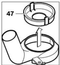
Pazna: Kod preseka glodanja veceg od 30 mm morate ukloniti ulozak 47 pritiskivanjem zatezne spojnice iz usisnog adaptera 24.
Dr. Egbert Schneider Senior Vice President Engineering
Dr. Eckerhard Strötgen
Head of Product Certification
Paa.
Robert Bosch GmbH, Power Tools Division D-70745 Leinfelden-Echterdingen 21.07.2008
Montaža
Dr. Egbert Schneider Senior Vice President Engineering
Dr. Eckerhard Strötgen
Head of Product Certification
Paa
Robert Bosch GmbH, Power Tools Division D-70745 Leinfelden-Echterdingen 21.07.2008
Montaža
Uldised ohutusjuhised
TAHELEPANU
Koik ohutusnouded ja juhised tuleb labl lugeda.
Dr. Egbert Schneider Senior Vice President Engineering
Dr. Eckerhard Strötgen
Head of Product Certification


Robert Bosch GmbH, Power Tools Division D-70745 Leinfelden-Echterdingen 21.07.2008
Montaž
Freesitera paigaldamine (vt joonist A)
Enne mistahes toode teostamist elektrilise toorista kallal tommake pistik pistikupesast valja.
Freesiterade paigaldamisel Ja vahetamisel on soovitav kanda kaitsekindaid.
Igaks kasutusotstarbeks on saadaval sobiva kvaliteediga freesiterad.
1-2 madalad poorded
3-4 keskmised poored
5-6 korged poorded
Dr. Egbert Schneider Senior Vice President Engineering
Dr. Eckerhard Strötgen
Head of Product Certification

i.v. Moju:
Robert Bosch GmbH, Power Tools Division
D-70745 Leinfelden-Echterdingen 21.07.2008


Pievienošana
Frezešanas darbinstrumenta iestiprinăsana (skatit attelu A)
Pirms elektroinstrumenta apkopes vai apkalposanas izvelciet ta elektrokabela kontaktdaksu no barojsa elektrotikla kontaktligzdas.
lestprinot un nomainot frezeshanas darbinstrumentus, ieteicams uzvikt aizsargcimdus.
Tirdzniecibas vietas var iegadaties visdaadakkas kvalitates un izpildijuma frezeshanas darbinstrumentus.
Frezeanas darbinstrumenti no atgriezegterauda ir piemeroi mikstu materiallu, piemeram, miksta koka un plastmasas apstradei.
Frezeesan darbinstrumenti ar cielmetala griezejskautnem ir ipaşi paredzeti cietu un abrazivu materilalu, piemeram, cieta koka un aluminija apstradei.
Originalos frezesanas darbinstrumentus no Bosch plaSA piederumu klasta var iegadaties specializetajas tirdzniecibas vietas.
lestipriniet tikai nebojatas un tiras frezes.
Nospiediet darbvarpstas fikseshanas taustinu 9 (0) un turiet to nospiestu. Ja nepieciesams, ar roku nedaudz pagrieziet darbvarpstu, lidz ta fiksjas. Nospiediet darbvarpstas fikseshanas taustinu 9 tikai laikā, kad elektron instruments nedarbojas.
- Atskruvejiet virsuzgiezni 11 ar valejo uzgieznu atslegu 21 (atslegas platums 24 mm), griezt to preteji pulkstenara raditaju kustibas virzienam (Θ).
- lebidiet frezeshanas darbinstrumenta katuturetajaptvere. Frezes katam jatrodas turetajaptvere vismaz 20 mm dzili.
- Stingri pieskrüvejiet virsuzgiezni 11 ar valejo uzgieznu atslegu 21 (atslegas platums 24mm , griezt o t pulkstenara dritaju kustibas virziena. Tad atlaidiet darbvarpstas fiksesanas taustinu 9.
Ja nav iestiprinata kopejoša vadote, neiestipriniet instrumenta frezesanas darbinstrumentus, kuru diamets parsniedz 50 mm. Šadi darbinstrumenti neiziet caur instrumenta pamatni.
Nepievelciet turetajaptveres virsuzgriezni, ja turetajaptvere nav ivietots darbinstrumenta kats. Sadi rikojoties, turetajaptvere var tikt bojata.
Puteklu un skaidu uzuksan (skatit attelu B)
Dazu materialu, piemeram, svinu saturoušu krāsu, dazu koksnes škirnu, mineralu un metalu putekji var būt kaitigi veselibai. Pieskar-sanas sadiem putekliem vail toeilposana var izraisit alergiskas reakcijas vail elposanas celu saslimsanu elektroinstrumenta lietotajam vaid darba vietai tuvumā esosajām personām. Atsevisku materialu putekli, piemeram, putekli, kas rodas, zagejot ozola vail dizskābarza koksni, var izraisit vezi, ipasi tad, ja koksne ieprieksirikusi kimiski apstrādata (ar hromatu vail koksnes aizsardžibas lidzekliem). Azbestu saturousus materialus drikst apstrā-dat vienigi personas aripāsam profesiónalam iemanam.
Dr. Egbert Schneider Senior Vice President Engineering
Dr. Eckerhard Strötgen
Head of Product Certification
Paa.
Robert Bosch GmbH, Power Tools Division D-70745 Leinfelden-Echterdingen 21.07.2008
Montavinas
Frezavimo jrankio jstatymas (ziur.pav.A)
Pries atliekant bet koklus elektrinio jrankio reguliavimo ar prieziuros darbus reikia istraukti kištuka is elektros tinklo lizdo.
Istatant ar keiiciant frezavimo jrankius, rekomenduojama muveti apsaugines pirstines.