
Twin 14000 - Water pump AL-KO - Free user manual and instructions
Find the device manual for free Twin 14000 AL-KO in PDF.
| Brand | AL-KO |
| Model | Twin 14000 |
| Product type | Submersible pump for clear and dirty water |
| Intended use | Water removal during floods, transfer or emptying of containers, water extraction from a well or pit, drainage water and overflow removal |
| Compatible liquids | Clean water, rainwater, chlorinated water, sanitary water, wastewater with up to 5% suspended solids |
| Thermal protection | Yes, with automatic shutdown in case of overheating and restart after 15-20 min |
| Operating mode | Automatic (via float switch) and manual |
| Residual water height | Possible in position 'O' of the adjustable foot (pumping down to very low height) |
| Maintenance and cleaning | Clean with clear water after using chlorinated water; clean the suction slots regularly |
| Electrical safety | Mandatory use with 30 mA residual current circuit breaker; extension cable H07RN-F with cross-section ≥1.5 mm² |
| Storage | Empty the pump and store it frost-free |
| Warranty | Legal warranty against manufacturing defects; repair or replacement according to conditions |
| After-sales service | Contact the nearest AL-KO service center (www.alko-garden.com/service-contacts) |
Frequently Asked Questions - Twin 14000 AL-KO
User questions about Twin 14000 AL-KO
0 question about this device. Answer the ones you know or ask your own.
Ask a new question about this device
Download the instructions for your Water pump in PDF format for free! Find your manual Twin 14000 - AL-KO and take your electronic device back in hand. On this page are published all the documents necessary for the use of your device. Twin 14000 by AL-KO.
USER MANUAL Twin 14000 AL-KO
AL-KO KOBER GROUP KOtz, Germany
This documentation or excerpts therefrom may not be reproduced or disclosed to third parties without the express permission of the AL-KO KOBER GROUP.
A
B

C
D
SUB 13000
TWIN 14000
H
1
J


| SUB 10000 DS (Art. Nr. 112 823) SUB 12000 DS (Art. Nr. 112 824) SUB 13000 DS (Art. Nr. 112 829) (Klarwasser) | TWIN 11000 (Art. Nr. 112 830) TWIN 14000 (Art. Nr. 112 831) (Klar-/Schmutzwasser) | SUB 11000 (Art. Nr. 113 508) (Klarwasser) |
| SUB 10000 DS: 450 W SUB 12000 DS: 550 W SUB 13000 DS: 650 W | TWIN 11000: 850 W TWIN 14000: 1000 W | 520 W |
| 230 V AC/50 Hz 230 V AC/50 Hz 230 V AC/50 Hz | ||
| X 8 X 8 X 8 | ||
| 5 m 7 m 5 m | ||
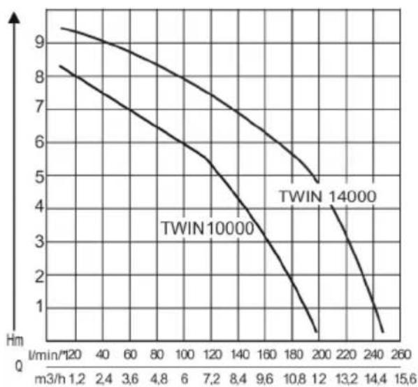
| SUB 10000 DS: 7 m SUB 12000 DS: 8 m SUB 13000 DS: 8 m | TWIN 11000: 10 m TWIN 14000: 10 m | 8 m |
| SUB 10000 DS: 8000 l/h SUB 12000 DS: 9500 l/h SUB 13000 DS: 10500 l/h | TWIN 11000: 13500 l/h TWIN 14000: 15000 l/h | 9000 l/h |
| 35 °C 35 °C 35 °C | ||
| 2,5 cm TWIN 11000: 5,0 cm TWIN 14000: 6,0 cm | 2,5 cm | |
| 3 mm TWIN 11000: 20 mm TWIN 14000: 30 mm | 3 mm | |
| SUB 10000 DS: 5,5 kg SUB 12000 DS: 5,8 kg SUB 13000 DS: 6,0 kg | TWIN 11000: 7,2 kg TWIN 14000: 8,4 kg | 5,8 kg |
| 3 mm 8 mm 3 mm | ||
| SUB 10000 DS cm: 37/15 - 39/17 SUB 12000 DS cm: 37/15 - 39/17 SUB 13000 DS cm: 13,5-21,5/11,5 - 15,5-23,5/13,5 | TWIN 11000 cm: 41/22 - 46/27 TWIN 14000 cm: 17,0-25,0/15,0 - 21,3-29,3/19,3 | 37/15 - 39/17 |
| 10 m 10 m 10 m |
1 About these operating instructions. 15
1.1 Symbols on the title page 15
1.2 Legends and signal words 15
2 Product description 16
2.1 Product overview 16
2.1.1 TWIN (Figure A) 16
2.1.2 SUB (Figure C). 16
2.2 Function 16
2.3 Position of adjustable foot.. 16
2.4 Thermal protection.. 16
2.5 Designated use 16
2.6 Possible misuse 16
3 Safety instructions. 17
3.1 General safety warnings.. 17
3.2 Electrical safety 17
4 Installation 18
4.1 Fitting the pressure line 18
4.1.1 TWIN (Figure A) 18
4.1.2 SUB (Figure C). 18
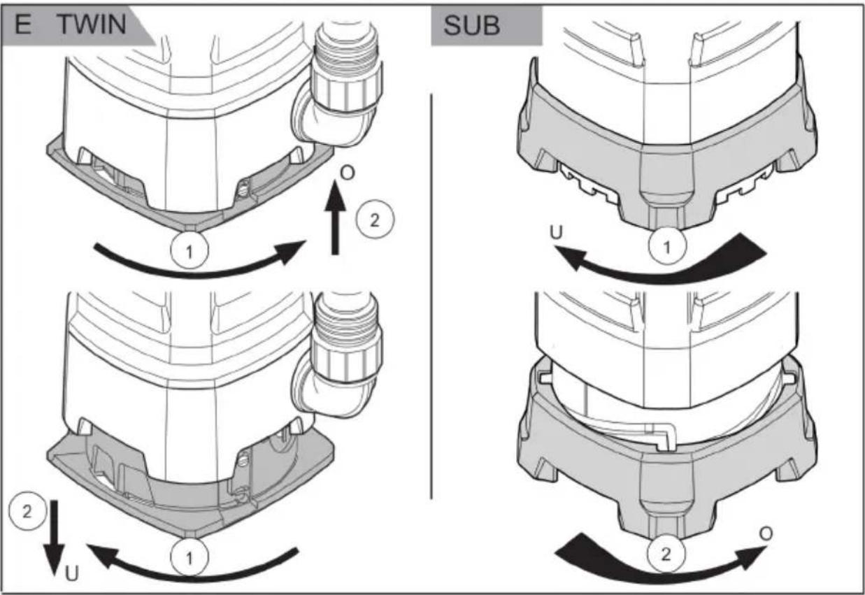
4.2 Adjustment of adjustable foot (Figure E) 18
4.2.1 TWIN 18
4.2.2 SUB. 18
5 Start-up 18
5.1 Safety 18
6 Operation 18
6.1 Switching the pump on 18
6.2 Switching the pump off 18
6.3 Automatic mode 18
6.4 Manual operation mode 19
6.5 Pumping out to residual water level... 19
7 Maintenance and care. 19
7.1 Cleaning the pump. 19
7.2 Removing/fitting the level switch..... 19
7.3 Removing/fitting the adjustable foot... 19
8 Help in case of malfunction. 19
9 Storage. 20
10 Disposal 20
11 After-Sales/Service 20
12 Information on the Declaration of Conformity 21
13 Warranty 21
1 ABOUT THESE OPERATING INSTRUCTIONS
The German version is the original operating instructions. All additional language versions are translations of the original operating instructions.
- Keep these operating instructions in a safe place at all times so that they can be consulted if you need any information about the appliance.
Only pass on the appliance to other persons together with these operating instructions.
Comply with the safety and warning information in these operating instructions.
1.1 Symbols on the title page
Symbol Meaning

It is essential to read through these operating instructions carefully before start-up. This is essential for safe working and trouble-free handling.

Operating instructions

To avoid electric shock, do not damage or cut the power cable!
1.2 Legends and signal words
DANGER! Denotes an imminently dangerous situation which will result in fatal or serious injury if not avoided.
WARNING! Denotes a potentially dangerous situation which can result in fatal or serious injury if not avoided.
CAUTION! Denotes a potentially dangerous situation which can result in minor or moderate injury if not avoided.
IMPORTANT! Denotes a situation which can result in material damage if not avoided.
NOTE Special instructions for ease of understanding and handling.
2 PRODUCT DESCRIPTION
Various models of pumps are described in these operating instructions. Identify your model from the identification plate.
2.1 Product overview
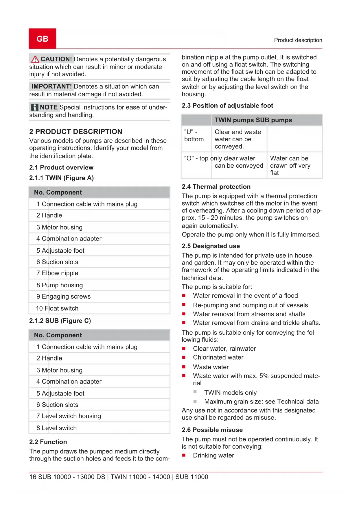
2.1.1 TWIN (Figure A)
| No. Component |
| 1 Connection cable with mains plug |
| 2 Handle |
| 3 Motor housing |
| 4 Combination adapter |
| 5 Adjustable foot |
| 6 Suction slots |
| 7 Elbow nipple |
| 8 Pump housing |
| 9 Engaging screws |
| 10 Float switch |
2.1.2 SUB (Figure C)
| No. Component |
| 1 Connection cable with mains plug |
| 2 Handle |
| 3 Motor housing |
| 4 Combination adapter |
| 5 Adjustable foot |
| 6 Suction slots |
| 7 Level switch housing |
| 8 Level switch |
2.2 Function
The pump draws the pumped medium directly through the suction holes and feeds it to the com
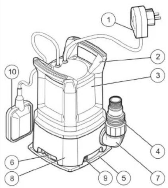
bination nipple at the pump outlet. It is switched on and off using a float switch. The switching movement of the float switch can be adapted to suit by adjusting the cable length on the float switch or by adjusting the level switch on the housing.
2.3 Position of adjustable foot
| TWIN pumps SUB pumps | ||
| "U" - bottom | Clear and waste water can be conveyed. | |
| "O" - top | only clear water can be conveyed | Water can be drawn off very flat |
2.4 Thermal protection
The pump is equipped with a thermal protection switch which switches off the motor in the event of overheating. After a cooling down period of approx. 15 - 20 minutes, the pump switches on again automatically.
Operate the pump only when it is fully immersed.
2.5 Designated use
The pump is intended for private use in house and garden. It may only be operated within the framework of the operating limits indicated in the technical data.
The pump is suitable for:
Water removal in the event of a flood
Re-pumping and pumping out of vessels
Water removal from streams and shafts
Water removal from drains and trickle shafts.
The pump is suitable only for conveying the following fluids:
Clear water, rainwater
Chlorinated water
Waste water
Waste water with max. 5% suspended material
TWIN models only
Maximum grain size: see Technical data
Any use not in accordance with this designated use shall be regarded as misuse.
2.6 Possible misuse
The pump must not be operated continuously. It is not suitable for conveying:
Drinking water
Salt water
Foodstuffs
aggressive media, chemicals
corrosive, flammable, explosive or fuming fluids
fluids that are hotter than 35^
water containing sand and abrasive fluids.
3 SAFETY INSTRUCTIONS
DANGER! Danger from contact with live parts! A defect in the pump or the extension cable can result in serious injury!
- Disconnect the connector plug from the mains immediately.
- Connect the device via an earth leakage circuit breaker with a rated leakage current of < 30 mA .
WARNING! Risk of injury. Defective and disabled safety and protective devices can result in serious injury.
Have any defective safety and protective devices repaired.
Never disable safety and protective devices.
CAUTION! Risk of burns from hot water! After extended use against the closed pressure side (>10min.) , the water in the pump can become very hot and may escape uncontrolled!
- Disconnect the pump from the mains supply and allow the pump and water to cool down.
Check the water level on the suction side.
Check the leak-tightness of the lines.
Check the installation of the suction and pressure lines.
Put the pump into operation again only after all the faults have been remedied!
3.1 General safety warnings
- Appliances can be used by persons with reduced physical, sensory or mental capabilities or lack of experience and knowledge if they have been given supervision or instruction concerning use of the appliance in a safe way and if they understand the hazards involved. Children shall not play with the appliance.
People with very strong and complex restrictions may have needs that exceed the instructions described here.
Pumps without indication that they are protected against the effect of freezing shall not be left outside during freezing weather conditions.
- Never lift, transport or affix the pump by the mains cable. Do not pull the mains cable in order to pull the mains plug out of the socket.
Unauthorised modifications or conversions to the pump are prohibited. Repairs may only be carried out by our customer service.
- Disconnect the mains plug before working on the device. Protect the mains plug against moisture.
Only use the pump and extension cable if they are in flawless technical condition. Damaged appliances must not be operated.
- Maintain a safe distance to persons or animals or switch off the pump if animals approach.
3.2 Electrical safety
The pump may not be operated while people are in the pool or pond.
The mains voltage at your location must comply with the information regarding mains voltage in the Technical Data. Do not use any other supply voltage.
The pump may only be operated on an electrical installation in accordance with DIN/VDE 0100, parts 737, 738 and 702. For fuse protection, a circuit breaker of 10A and an earth leakage circuit breaker with a rated leakage current of 10/30mA must be installed.
Only use extension leads approved for outdoor use with a minimum cross-section of 1.5mm^2 Always fully unwind cable drums.
Damaged or fragile extension cables may not be used.
Check the condition of your extension lead prior to every use.
If the connection cable must be extended, only a cable type H07RN-F and a moulded sleeve must be used. This work must only be carried out by an electrician.
If the supply cord is damaged, it must be replaced by the manufacturer, its service agent or similarly qualified persons in order to avoid a hazard.
4 INSTALLATION
4.1 Fitting the pressure line
4.1.1 TWIN (Figure A)
- Screw connecting bracket (7) into the pump outlet.
- Bolt combination nipple (4) to the connecting bracket.
- Connect hose to combination nipple.
4.1.2 SUB (Figure C)
- Bolt combination nipple (4) to the connecting bracket.
- Connect hose to combination nipple.
NOTE The combination nipple can be trimmed to suit the selected hose connection. Use the largest possible hose diameter.
4.2 Adjustment of adjustable foot (Figure E)
4.2.1 TWIN
- Turn adjustable foot (6) to the right. The adjustable foot is disengaged.
- Move adjustable foot to position "O" or "U".
- Turn adjustable foot to the left. The adjustable foot engages again.
4.2.2 SUB
- Turn the adjustable foot 90^ to the left to move the adjustable foot to the top position.
- Turn the adjustable foot 90^ to the right to move the adjustable foot to the bottom position.
NOTE The combination nipple can be trimmed to suit the selected hose connection. Use the largest possible hose diameter.
5 START-UP
5.1 Safety
IMPORTANT! Risk of flooding! In the event of faults in the pump, water can escape and cause consequential damage due to flooding.
Take appropriate measures to avoid consequential damage caused by flooding in the event of faults in the pump.
- Operate the pump suspended from a cable or pay attention top a stable position of the pump.
Operate the pump only when it is fully immersed.
Make sure there is adequate clearance under the pump.
- Never allow the pump to run against a closed pressure line.
- When using in shafts, make sure the size is adequate.
Always cover the shaft with a secure footplate.
6 OPERATION
6.1 Switching the pump on
IMPORTANT! Danger of damage to the pump! The pump must not draw in any solid material. Sand and other abrasive materials in the pumped medium will destroy the pump.
Ensure that no solids can enter the pumped medium.
- Completely unwind mains cable (1).
- Ensure that electrical plug connections are located in the area safe from flooding.
Models with float switch
- Change the clamping position and set the switching points of float switch (10) individually.
- Clamp cable of float switch to the pump housing. Recommended cable length on the float switch approx. 100mm
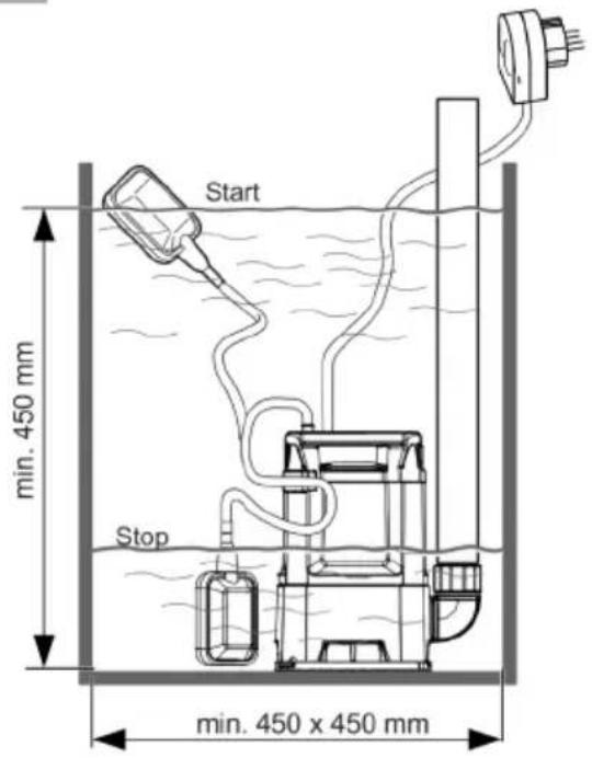
Models with level switch
NOTE Use a suitable plate to ensure stable standing of the pump on muddy, sandy or stony ground.
- Push level switch (8) to the corresponding height to set the switching points.
- Slowly immerse the pump in the pumped medium, holding the pump at a slight angle so that any trapped air can escape.
- Insert the mains plug into the power socket. The pump switches on automatically using the float switch when a specific water level has been reached, and switches off again if the water drops below the switch-off height.
6.2 Switching the pump off
- Remove the mains plug from the plug socket.
6.3 Automatic mode
-
In automatic mode, set the adjustable foot to position "U" (bottom) to achieve the greatest possible feed rate.
-
Insert the mains plug into the power socket.
Models with float switch
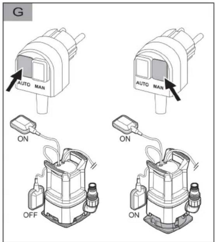
- Turn the operating mode selector switch on the mains switch to "AUTO" (Fig. G).
Models with level switch
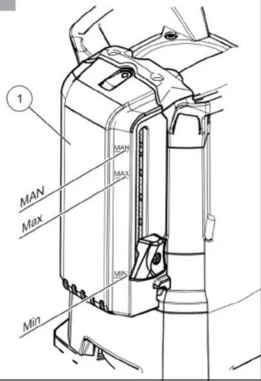
- Push the level switch upwards to the desired switch-on height (Fig. 1).
The pump is switched on automatically by the float switch at a specific water level (switch-on height) and switches off again when the water level falls to the switch-off height, see technical data.
6.4 Manual operation mode
In manual mode, the water can be pumped away to a very low level of residual water.
Minimum water level for commissioning: see Technical data.
6.5 Pumping out to residual water level
IMPORTANT! Danger of damage to the pump! There is a danger during pumping out that the pump could run dry and cause equipment damage.
Monitor the pump continuously when pumping out to the residual water level and avoid the pump running dry.
Take the pump out of service when the residual water level is reached by pulling out the mains plug.
Set the adjustable foot to the "O" (top) position for pumping out to the residual water level:
- Remove the mains plug from the plug socket.
Models with float switch
- Turn the operating mode selector switch to "MAN" (Fig. G). The pump switches on and starts to feed.
Models with level switch
- Push the level switch upwards to the "MAN" position (Fig. I).
NOTE If the water drops below the residual water level, the pump will draw air in. In this case, the pump must be vented when the water level rises and before using it again.
7 MAINTENANCE AND CARE
7.1 Cleaning the pump
NOTE After conveying swimming pool water containing chlorine or fluids that leave residues, the pump must be flushed out with clear water.
- Clean the suction slots on the suction foot with clear water, if necessary.
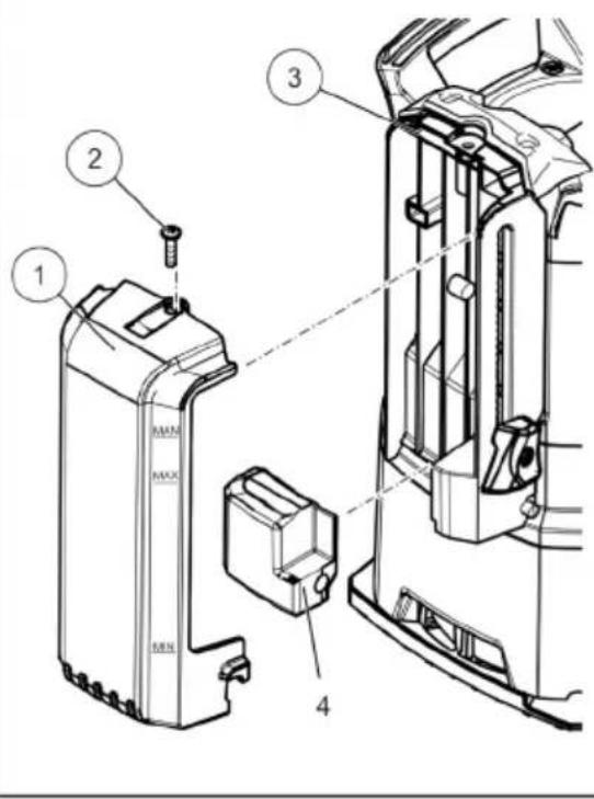
7.2 Removing/fitting the level switch
- Unscrew mounting bolt (2), then push housing level switch(1) upwards and then tilt to the front.
- Clean the float (4) and guides (3).
- Place the float back in the guide.
- Replace the housing level switch and push downwards.
- Screw in the mounting bolt.
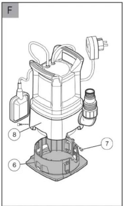
7.3 Removing/fitting the adjustable foot TWIN pump
- Unscrew engaging screws (7) and pull adjustable foot (6) out of pump housing (8).
- Clean adjustable foot and pump housing.
- Insert adjustable foot in pump housing, align and screw in engaging screws again.
8 HELP IN CASE OF MALFUNCTION
DANGER! Danger of electric shock!
There is a risk of electric shock when working on the pump.
- Disconnect the mains plug before starting any fault remedying work.
- Faults in the electrical system must be rectified by a qualified electrician.
NOTE In the event of faults that you cannot rectify, please contact our Customer Service department.
| Malfunction Possible cause | Remedy | |
| Motor does not run. Impeller blocked. Remove dirt from the suction area. | ||
| Clean with a suitable tool through the opening on the back of the motor housing. | ||
| Thermal protection switch has switched off. | Wait until the thermal protection switch on the pump switches on again. Take note of the maximum temperature of the conveying medium. Have the pump inspected. | |
| No mains power. Check fuses, have the power supply checked by a qualified electrician. | ||
| Float switch does not switch off when the water level rises. | Send the pump to an AL-KO service facility. | |
| Pump running but does not feed. | Air in pump housing. Dry running, automatic switch-off after 90 seconds. | Vent the pump by holding it at an angle. Adjust the adjustable foot correctly. |
| Blockage on the suction side. Remove dirt from the suction area. | ||
| Pressure line closed off. Open the pressure lone. | ||
| Pressure hose kinked. Extend the pressure hose. | ||
| Delivery rate too low. Hose diameter too small. Use a hose with a bigger diameter. | ||
| Blockage on the suction side. Remove dirt from the suction area. | ||
| Feed head to high. Observe max. feed head, see technical data! | ||
| Only pumps with level switch | ||
| Pump running continuously. Float body blocked. Switch set incorrectly. | Clean the float body. Adjust the switch correctly. | |
| Pump is always off. Float body blocked. Water level too low. | Clean the float body. | |
9 STORAGE
NOTE If there is the danger of frost, the system must be completely drained and the pump must be stored in a frost-proof place.
10 DISPOSAL

Electrical and electronic appliances do not belong in household waste, but should be collected and disposed of separately.
Packaging, equipment and accessories are made from recyclable materials, and must be disposed of accordingly.
11 AFTER-SALES/SERVICE
In the event of questions of warranty, repair or spare parts, please contact your nearest AL-KO Service Centre. These can be found on the Internet at: www.alko-garden.com/service-contacts
Further information on spare parts can be found at: www.alko-garden.com/spareparts
12 INFORMATION ON THE DECLARATION OF CONFORMITY
We hereby declare, as the exclusively responsible party, that this product in its marketed form
meets the requirements of the harmonised EU Directives, EU safety standards and the product-specific standards. The Declaration of Conformity forms part of the operating instructions and is included with the machine.
13 WARRANTY
We will remedy any material or manufacturing defects discovered in the device during the statutory period of limitation for claims for defects by repair or replacement at our discretion. The period of limitation is determined in each case by the law of the country in which the device was purchased.
Our warranty promise applies only if:
These operating instructions are observed
The device is handled correctly
Original spare parts have been used
The warranty becomes void in the case of:
Unauthorised repair attempts
Unauthorised technical modifications
Use for other than the intended purpose
The warranty does not include:
Paint damage attributable to normal wear
Wear parts that are marked with a box xxxxx (x) on the spare parts card
The warranty period commences with the purchase by the first end user. The date on the proof of purchase is decisive. In the event of a warranty claim, please contact your dealer or the nearest authorised customer service centre with this declaration and the original proof of purchase. This declaration does not affect the purchaser's statutory claims for defects against the vendor.
VERTALING VAN DE ORIGINELE GEBRUIKERSHANDLEIDING
Inhoudsopgave
2 PRODUCTBESCHRIJVING
2.1.2 SUB (Figure C)
4.1.2 SUB (Figure C)
3 BEZPEČNOSTNÉ POKNY
NEBEZPECENSTVO! Nebezpecenstvo pri dotyku dielov veducich napatie! Chyba na cerpadle alebo predlzovacom kablmi moze viest'k vaznym zraneniam!
Zastrchu okamzite vytiahnite zo zasuvky elektricnej siete.
Pristroj pripoje cez ochranny spinae FI s menovitym chybovym prudom < 30mA
VAROVANIE! Nebezpečenstvo zranenia.
2.3 Allithato lab beallitasa
Pumpen ar lamplig for:
7 VEDLIKEHOLD OG PLEIE
7.1 Rengjore pumpen
4.1 Scurvetoru monteerimine
4.1.1 TWIN (joonis A)
2.1.2 SUB (C attels)
Nr. Detala
2.1.2 SUB (Φnrgypa C)
4.1.2 SUB (Φnrgypa C)
- 3aBnHTeTe KOM6HnHpaHn HnpeI (4) Bbpxy Cbbp3BaUaTa cKo6a.
- CbpxTe Mapkya KbM Kom6nHupaHn HnneJ.
YKA3AHNE Kom6HnHaHnT HnneI MoKe Da ce Otpexe CbO6pa3Ho N36paHaTa BpB3Ka 3a MapKyu. N3NoJ3BaIte Bb3MOxHO Ha-ROJeMnДnAmEtbp Ha MapKya.
4.2 HactpoBbAHe Ha peryIpyEmnKpaK(ФИrgpaE)
4.2.1 TWIN
1.3aBbptTepeRyIpyEmnKpaK(6)HaAraCHO. PerynpemymT KpaK ce ocbo6oxdaBa.
2. HactpoTe perynpyemna kpaB noIooKeHne "O" nnn "U".
3. 3aBbptTepeRyIpyEmnKpaKHaJIBO.PeRyIpyEmnT KpaK ce npNbnpa Ha MAcToTO cn.
4.2.2 SUB
1.3aBbptetepepymemyKpaKaHa 90^ HaNBA,3a Da IIOCTaBNTe B TropHO NIOXKeHne.
2. 3abptete perynpemyka KaHa 90^ Ha- dACHO, 3a Da ITO NOCTABNTe B DOHNOJIOKeHne.
YKA3AHNE Kom6HnHaHnT HnneJ MoKe Da ce OtpeKe cbo6pa3Ho n36paHaTa Bpb3Ka 3a Mapky. N3noJ3BaIte Bb3MOxHO Ha-TOJeMna DnAmEtbp Ha Mapkyua.
6.5 N3nOMnBaHe Do HnBOTO HaOCTaTbUHaTa BODa
BHIMAHHE! OnachocT OT NOBpeHn Ha ypeHa! Pn n3POMnBaHe CbIeCTByBa PNCK NOMnata Da pa60Tu Ha cyxo, KOeTO MOKe Da IOBeDe Do NOBpeHa Ha ypeHa.
Ha6nIpaBaIte nomnata noCToHNO npn n3-nomnBaHe Do HNBOTo Ha OCTaTbUHaTa BOda He dOnyckaIte nomnata da pa6Otn Ha cyxo.
IpndoCTnraHeHaHNBOToHaOCTaTbUHaTa BOda CnpTe NOMnata OppaOta Upe3 N3- BaxdaHe Ha uenceHa.
3a Da H3NOMNBATE DO HNBOTO Ha OCTaTByHaTAt BOda, NOCTaBeTe peryInpyemn KpaK B noJIOKeHne "O" (Harope):
1.ИЗклочete敛encela ot KOHTaKta.
Moden C nonlaBueh npeKbcBa
Moei n ppeBknoyBaTeI Ha HnBOTo
1.ПиьзhteпревкючытелнаНИВОТHaropeВ полжени"MAN"(PbUHO)(ФИR.I).
YKA3AHNE Ako ce naIHe NOd HNBOTo Ha OCTaTbUHaTa BOda, NOMnata 3acMyKBa Bb3dyx. B TO3n Cnyuay npi NobuShaBaUc Ce HnBO Ha BOda-Ta I npedn NOBtOpHa pa6Ota, NOMnata Tpr6Ba Da ce o6e3Bb3dUSh.
7 NOДРьЖKA И NOЧNTBAHE
7.1 NocHTBaHe Ha NOMnata
YKA3AHNE CneI n3nomBaHe Ha B0da OT npyBeH baceH, cIbPkaaXnOp IIN TeuHOcTn, KOnTO OCTaBt OCTaTbU, NOMNaTa Tp6Ba Da ce n3PnaKHe C YnCTa B0da.
- Ako e Heo6xOdmo, NouchTeTe c Yncta Boda CmyKaTeJIHnTe OTBOpn Ha KpaYeTo 3a 3acMyKBaHe.
7.2 DeMOHTaX/MOHTaX Ha npeBkIIOUyBaTeJHa HNBOTO
-
OTBnIe qnknpaun BnHT (2) n cTbHeTe npEbkIIOvBaTeJHa HnBOTO Ha Kopnyca (1) nbpBO HaOpe, a CneD TOBa HnpeJd.
2.ПоистeteТЯлOTHa nonlaBbka(4)ИВODa-упte(3). -
NocTabete OTHOBO TANOTO Ha nonlaBka BbB BOdaça.
- Пocтавete превкючытел Ha HNBOTo Ha TЯлOTO И Го HAtИСнЧe Надoly.
5.3aBnIeΦnKcnpauny BnHT.
7.3 Pa3rno6BaHe/crno6BaHe Ha perynnpyemna KpaK
TOMNA TWIN
- OTBnTe qnknpaunTe BnHTOBe (7) n 3-DbpnaTe pepynpyemna KpaK (6) ot Kopnyca Ha nomnata (8).
- Почисте ренихся Крак И Корпуca на nomпа. Ангеля.
- Пocтавete ретуларемя крак в Корпуca наnomnaTa, поразовто Ги 3аьитeto OTHOBOФИКСИРашпто ВИNTОBE.
8 NOMOUI PNI HEN3INPABHOCTN
ONACHOCT! OnachocT OT TOKOB yap!
Pnpapobota c nomnata cbueCTbByBa onaCHOCT OT TOKOB ynap.
IpeIN BCNUK N DeHOCn NO OCTpaHBAHe Ha HEn3npaBHOCTN N3KJIIOHTe UenceJa.
IobpeHte B eJekTpueckaTa CnCTema Tp6Ba Da ce OTCpaHrT OT KBaJIuΦnUpaH eJekTpOTexHnK.
YKA3AHNE B cnyuha Ha HeoCTpaHIMn He-3npaBHOCTN,MOJ,CBbpxKeTe Ce C HauINr OT-DeI 3a 06cnykBaHe Ha KIneHTN.
| Helen III 武漢中華人民出版社 Hebei 武漢中華人民出版社 Helen III 武漢中華人民出版社 Helen III 武漢中華人民出版社 Helen III 武漢中華人民出版社 Helen III 武漢中華人民出版社 Helen III 武漢中華人民出版社 Helen III 武漢中華人民出版社 Helen III 武漢中華人民出版社 Helen III 武漢中華人民出版社 Helen III 武漢中華人民出版社 Helen III Helen III Helen III Helen III Helen III Helen III Helen III Helen III Helen III Helen III Helen III Helen III Helen III Helen III Helen III Helen III Helen III Helen III Helen III Helen III Helen III Helen III Helen III Helen III Helen III HelenIII Helen III Helen III Helen III Helen III Helen III Helen III Helen III Helen III Helen III Helen III Helen III Helen III Helen III Helen III Helen III Helen III Helen III Helen III Helen III Helen III Helen III Helen III Helen III Helen III Helen Ⅲ Helen Ⅲ Helen Ⅲ Helen Ⅲ Helen Ⅲ Helen Ⅲ Helen Ⅲ Helen Ⅲ Helen Ⅲ Helen Ⅲ Helen Ⅲ Helen Ⅲ Helen Ⅲ Helen Ⅲ Helen Ⅲ Helen Ⅲ Helen Ⅲ Helen Helen Helen Helen Helen Helen Helen Helen Helen Helen Helen Helen Helen Helen Helen Helen Helen Helen Helen Helen Helen Helen Helen Helen Helen Helen Helen Helen Helen Helen Helen Helen Helen Helen | |
| Двигателей не павOTи. РавOTи. ПавOTи Нотою Колею e 6лokира- но. Терmonpaneкьсвачыт e ИЗлio- чл. Нама сел'tупесло наразе- нце. Палавьочит рекьсваче сe повиша- вахе на НИВОТ ha BODaTa. | Одстранеше замьрсявенита в 30- ната на засмунке. Почистete пгел отвора в 3адната част на кор- пуca на двигателя с поховяи, нстру金融市场. Изчakайte, дOKATO Терmonpaneкьсва- чыт OTROBO BKNIOUчиnomпата. Оьгрипеше Вимане на максимал- ната Temпегатура на ИЗПOMNBВана- та среда.Проберete nomпата. Праздпаизinteите, се ektrpoэхсан- ваныт Травьда на сьдатnombere- ни OTеlektroTEXнIC. Изrancesе помпата в серви体育场н. центыр ha AL-KO. |
| Helen3правноct Вьзможна ручна OTсравванe | |
| Помпата павOTи, по не до вда вoda. | Вьздунх в корпuya на_nomда. Равotingу на сухо, обтоatingу на: изключвае сдеД 90 секунд. |
| Занишвае на симкутелнастара. | |
| Налорниот маркуопровod e за Творен. | |
| Претынат марку 3a на ляга- He. | |
| Тьрдешка скорост на досtabka | Диамettingу на маркуа e Тьрде мальК. |
| Занишвае на симкутелнастара. | |
| Прекален goлиma височина на Deбида. |
YKA3AHNE Ako nma ONaCHOCT OT 3aMpb3BaHe, CnCTemata Tp6Ba Da ce N3TOUH HAnbJHO I NOMPATA Da ce CbXpaHRA Ha 3aUNTeHO OT 3aMpb3BaHe MRCTO.
10 N3XBbPJIaHE

EneKtpnuecknte n eJeKtpoHHnte ypeDi He npHaIJIeXaT KbM 6NtOBnTe OTnaIbU, a HAnpOTnB HAnarat OTdEnHO cb6npaHe n 3XBpbJrHe!
12 INHOPMAU3A DEKJIAPAUYTA 3A CbOTBETCTBNE
C HacToIto DeKnapPame Ha CBOA OTROBOPHOCT, Ye To3n IpoDyKT BbB φOpMaTa, B KOrTo e npedlaRaH Ha Na3apa, N3NbJIHRABa N3NCKBaHnraTa
Onakobkata,ypeBtI npHaJnxHocHTe ca npon3BeDeHN OT noJnxKaun Ha peuKnnpaHe MaTePnaN IN Tp6Ba Da ce N3XBpNAT B CbOTBETCTBNE C TOBA.
11 IOДРьЖKA /CEPBN3
3a Bbnpocn OTHOCHO rapaHcnaTa,peMOHTa NINI NOdMaHaTHa Ha YactN, MoJ, CBpKeTe Ce c Hau6bnKnA cepBn3eH ceHTbp Ha AL-KO. Ie ro otKpnEte B nHTepHeT Ha cneDnA aDpec: www.alko-garden.com/service-contacts
3a NOBue HNΦopMaζη OTHOCHO pe3epBn YacTN NocTeTe: www.alko-garden.com/spareparts
HaXapMOH3npuHNTe DnpeKtNB Ha EU, cTaHdaptNTe 3a 6e3oNaChocT Ha EU n cTaHdaptNTe 3a CneuΦnHTe npOdykTN. JeKnapaunra Ta 3a CbOTBeTCTBnE e qact OT HnCtpyKUraTa 3a ekCnloataun i e npInOKeHa KbMaunHaTa.
13 TAPAHUN
BcKaKbMaTePnAaHn nn npOn3BOdCTBeHn DepeKTn no ypeHa ce OTCTpaHraBaT OT hac npe3 3aKoHOBnnaBbOCTeH cPok 3a npTeHcun 3a HeIOCTaTbU, no Hau n36Op ype3 peMOHT nnn 3aMeCTBaUdaocTabka. DaBHOCTHnT cPok ce onpeJeIeN CbOTBeTHO cNopeI 3aKOHHe Ha CTpaHaTa, KbJeTo e npOdaen ypeDbT.
Haata rapaun Baxn camo npi:
Cn3BaHe Ha Ta3n HNCTpyKzna 3a ekcnnoatau
PpaBnHa ynoTpe6a
3no3BaHe Ha opuHaHn peepBHu actu
TapaHcIyTa cTaBa HeBaJIuHa npi:
OHTN3a cAMOBONH peMOHTN
CamaBoJHnTexHnueckn 3MeHeHnA
YnoTpe6a He no npedHa3HaueHne
OT rapaunraTa ce n3knHouBaT:
LTeTn no JAKOBOT NOKPITNE, Bb3HnKHaJI N BCJeCDTBne Ha HOpMaJHO 3HOCBaHe
Бьр30 ИЗнOCВаши ce части, кОТо Ha KapTaTа C peЗерВнite ча STС OЗнЧЕНС paMkaXXXXXX (X)
IapauHIOHNnT nepno3aNoBa da Teue cneI NOKyNkata OT CtpaHa Ha IpbBna KpaenOTpe6nte. OnpeJeIa e DaTaHa Na DOKymeHTa 3a NOKynka. MoJ, obpHeTe ce c Ta3n DeKnapaun n opuHnHaIIHHaDOKymeHT 3a NOKyNk KaM BaUNr TbPBOBcN ppeCTaBNTeJI nn Hain-6n3Kn r eHTbp 3a O6CnyXbaHe Ha KIneHTn. 3aKOHOBnTE PpeTeHUn 3a DeΦeKTn OT CtpaHa Ha KynBaUa KbM npOdaBaua OCTabat HENpOMeHEn OT Ta3n DeKnapaun.
IPEBOD OPINHJIbHOPO PYKOBODCTBA IO 3KcIIYATAUIn OrnaBHeHne
1 INHOpMaun O pyKOBODCTBe No 3KcNpy-atau.. 151
1.1 CmboIbHa TtTybHoi cTpaHnue ... 151
1.2 YcnoBhpie 6o3HaueHn n CnHaJIb-HbIe cNoBa 152
2 OnscaHne npoDyKta 152
2.1 O63op npoDyKTa 152
2.1.1 TWIN (pnc.A) 152
2.1.2 SUB (pnc.C) 152
2.2PnHcnp DeiCTBna 152
2.3 IonoKeHne perynipyemoi HoxKn 152
2.4 Tenaobar 3aunTa 152
2.5 NcnoJb3ObaHnne no Ha3HaueHnIO..... 153
2.6 CnyuHn HnpaBnIbHor npImeHn153
3 Yka3aHnno TeXnke 6e3oNaChocTn..... 153
3.1 O6uine yka3aHnI IO TexHnke 6e30- nachocTu. 153
3.2 3neKtpnuecka 6e3onacHocTb..... 154
4 YcTaHOBka. 154
4.1 MoHTaX HAnOpHOro Tpy6OpPoBa... 154
4.1.1 TWIN (pnc.A) 154
4.1.2 SUB (pnc.C) 154
4.2 Hac troka perynpyemoh Hoxkn (pncyHok E) 154
4.2.1 TWIN 154
4.2.2 SUB. 154
5BBoD B 3KcPJIyaTaUIO 155
5.1 Be3onacHocTb 155
6 UnpaBneHne 155
6.1 BkIIOueHne Hacoca. 155
6.2 OTKIIIOHHe Hacoca 155
6.3 ABTomatueckn pexum 155
6.4 Puynoi peXm 155
6.5 OTKaunBaHne Do MInHmAlbHoro y- poBHa 156
7 Texo6cnykubahne u yxo.. 156
7.1 Ouchka Hacoca 156
7.2 ChrTne/yCTaHObKa peJe ypoBnA....156
7.3 ChTne/ycTaHOBka perynpyeMoH HoxKn 156
8 YcTpaHeHHe HncPbBnOtei 156
9 Xpahene 158
10yttnnaa 158
11 CepBnchoe o6cnykBaHne 158
12 INHOpMaIy O DeKJIapaCNI COOTBeTCTBIA 158
13 TapaHTn 158
1 INHΦOPMAUЯ O PYKOBODCTBE ПО ЗКСПЛУATAЦИ
HemeckaBepncoepknt opunnaHbHoe pykoBoCTBO nO 3KcnIyatauIN. Bce ocTaNbHbIE y3bIKOBbie BepCN — 3TO nepeBOdbI opUNHaJIbHOpykoBOCTBa nO 3KcnIyatauIN.
Bcerda depknte 3TO pykoOIOCTBO nO 3Kc- pnyataunno pyko, TTo6bI npouHTaTb ero, ecn Bam notpe6yETcHΦopMaucna o6 y- cTpoiCTBe.
IpeepaBaiTe yCTpOcTBo dpymIMnUam TOJIbKO BMeCTe C 3TmPyKOBODCTBOM IO 3Kc- nIyatauH.
IpoTnte n co6nOdaite yka3aHnna no TexHnke 6e3oNaChocTu n npEduPpeJxDeHnra, npuBeHeHHbE B daHHOM pyKOBODCTBe nO 3KcNpyataun.
1.1 CnMBOJIbI Ha TtTyIbHoi CTpaHnce
CnmboJ 3HaueHne

O63aTeIbHO npouHTaTe daHHepeyKOBOcTBo NO 3KcnpyaTuNnepeB B0oM B 3KcnnyatauNo.3To Heo6xOIMO dnn 6e3OnacHOn n 6e3OTKa3HO pa6oTbl.

PykoBoDCTBO no 3KcnnyaTaun

CneInte 3a TeM, YTO6bI He NOBpeDnITb HIN He pa3OpBaTb CeTeBOJ Ka6eJIb, YTO6bI N36ExKaTb NopaxeHINAJIeKTPnueckm TOKOM!
1.2 YcNoBHbIe 06o3HaueHn I cnHaNbHbIe CNoBa
ONACHOCTb! Yka3bIbaeT Ha onaChyu CNTyaunIO, KOtOpA, ecn ee He n36eKaTb, npNBO-DNT K CMEptN INN cepBe3HbIM TpaBMam.
NPEdUnPExKDeHHe! Yka3bIbaeT Ha NOTehuHaNoIaChyU CNTyaUHO, KOToPAJ, ecn ee He H36ExKaTb, MoKeT npNBecTN K CMEpTN IJI N cepBe3- HBIM TpaBMam.
OCTOPOXHO! Yka3bIbaeT Ha NoteHcuaJIb-HO ONaCHyIO CNTyaCNIIO, KOTopA, ecN ee He N3-6exKaTb, MOKeT npNBecTn TpaBMam JERKoN I cpeDHei TjXeCTN.
BHIMAHHE! Yka3bIbaeT Ha cnTyauuH, KOTOpaar, ecn ee He n36eKaTb, MoKeT npNBecTu K NMyueCTBeHHOMy yuep6y.
H NPMMEUAHNE CneuaJIbHbIe yka3aHnA Jn o6JIeueHnnoHmHaHn I KcNJIyatau.
2 OПИСАНЕ ПОДУКТА
B 3TOM pykoOIOCTBE NO 3KcNJIyatauIN OINCAHbI pa3HbIE MoJeHn HAcOCOB. HyKHyO MoJeJb MOKHO IeHTnΦHnIpOBA Tb No HOMepy Ha 3aBOdCKoT Ta6NIuKe.
2.1 O63op npoodykta
Data npOn3BODCTBa
Даразпоиьдва Идения уka3ан Ha 3aBOdCKОТ tabичke.Даразпоиьдва COOTBETCTByETпервIM cheTbIpem Uфрam cepинHOrO HOMepa IX YZZ - AAAAAA.
X: roD npOn3BODCTBa
Y: mecaI npOn3BOIDCTBa (A = rHbapb)
ZZ:ДeHb npOu3B0dCTBa
2.1.1 TWIN (pnc.A)
BpyHOMpeKIMe BDOyMOKHOOTKaayTbdoOueHB Hn3KOrO ypOBH.
MnHMaBHyI yPoBeHb BObI dIa BBoDa B3KcPnPyatauIO: CM. TexHnueckne XapakTepncTkn.
6.5 OTKaUBaHne Do MmHmJaIbHoRO yPOBHa
BHHMAHNE! OnachocTb NOBpeXdEHNs O-60pydoBaHn! B cIyuee OTKaUKN eCTb ONACHOCTb 3ayncKa HacOca BCxyu N IOBpeXdEHNs O-60pydoBaHn I3-3a 3TOrO.
IIOCTOHHo KOHTPOINpyuTe HAcOC npN OTka- YnBaHn DO MInHMaJIbHO rpoBHa, He Do- NyckaIte cyxoro xOda Hacoca.
BbIKIOUHTe HAcOC pN DoCTNXeHm MNHMaJIbHOrO yPOBnJxIDKOCTN, BbIHyCteBOuI TeKep n3 p03eTKn.
Длг OTkaunBaHЯ Do MInHmAlbHOrO ypoBHy yctaHOBnTe peryIpyeMyIO HOKky B nOLOXKeHne «O» (Bvepx):
- BbHbTe WTeKep n3 po3eTKn.
MOnJIcNONJaBKOBBIM BbIKIOyAteJeM
1.перевдente пеклочаель ржимов в поожене MAN (Pyн.) (pnc. G).Hacoc BкючITcЯ начETпекаЧВаТь кIDКОCTb.
Moei nppe ypoBna
- NpeBnHbTe peJe ypoBn BBepx B noIooKeHne MAN (PyuH.) (pnc. I).
IINHMaJIbHO, HAcOC HaHcET BTrrNBaTb BO3dYx. B 3tOM cIyuae n3 HAcOca HxHIO BblNyCTnTB BO3- dYx npN yBeJIuHcEHn YPOBnJxNkOCTn NpePeI NOBTOPbIM 3aNycOM.
7 TEXOBCLNYKUBAHNE I YXOD
7.1 OuIncTka Hacoca
I INPIMEUYAHNE Iocne nepekaunBaHncaOpdepaueiXlop BOdbI n3 baccenHa nnJxNkOCTeN, OCTaBnaIOuNX HaneT, HAcOC Heo6xoNDMO npombAtb YnCTO BDOJ.
- Пи HeobxOДIMOCtI npOuNCTte IeJI N BcaCbIBaHnO OCHOBAHnY UcTOn BOdoN.
7.2 Chrtne/ycTaHOBka peJe ypoBnA
- OTBnHTnTe KpeEnKHbI BnHT (2) n OTKnHbTe Kopnyc peNe ypoBn (1) chauana BBepx, 3a-tem BnepeD.
- Ouicntte nonlaBok (4) n HaprabJIOue (3).
- CHOBA BCTaBbTe NnonlaBOK B HnpaBnaIOUne.
- YctaHOBnTe KOpnyc peIe ypoBHa Ma MeTo n npNXMnTE BHN3.
- 3aBnHTnte KpeNekHbI BnHT.
7.3 ChrTne/ycTaHOBka peryInpyeMoH HOXKN
Hacoc TWIN
- OTBnHTnte cTOnOpHbIe BnHTbI (7) n N3BneKeN-Te peryInpemyHOxKky (6) n3 Kopnyca Ha-coca (8).
- OuHCTHTe peRyIINpyEMyU HOXKU IN KOpNyc HAcOca.
- BcTaBbTe peryIpyeMyIO HOxKy B Kopnyc HAcocca, BbIPOBHnTe ee n CHOba 3aBepHnTe CTOnOpHbIe BNHTbl.
8 YCTPAHEHNE HENCINPABHOCTE
ONACHOCTb! OnachocTb nopaxeHn 3-NeKtpnueckn Tom! Pnp pa6oTe c HacocomEcTb onachocTb noIyueHn 3JneKtpnueckoro yda-pa.
Ipeed IIO6bIMpa6OTAMn NO yCTpaHEnHHeNCpapBHOCTe BbIHMaTe n3 po3ETKn CeTeBOJ Ka6eJIb.
HeincpaBHOCTn 3JneKtpocncTeMbI DOJXHbI y-ctpaHrTb npOeCCNOHaJIbHbIe 3JneKtpnKn.
H PIMMEUAHNE Ecnn HeucnpaBHOCTb He ydaetc yctpaHnTb, o6paauaTeCb B Hauy cepBnCHyO cnyk6y.
| HéncnPraBnOcTb Bo3MoJxHaj prinuHa CnOco6 yCtpanHeHJ | |
| Двигаел' He pa6oTaet. 3a6IokPobAHO pa6oOee Ko- neCo. | YdaJIte 3aIapRz3HeHHe Na UyacTke BcsabHAnH. Ycepe3 OTbepCTne c3a- dI Na KOpNcSe DVBatEJa OunchTe erO c POMOChU OpDxOJaUeTo HN- CTpyMeNTa. |
| TepMopel' eOtkIooHIO dBVra- teIb. | |
| Het cTeBOrO NaPraJxHeH. IprOBte ppeOxpaHnte, npoy- chte 3JeKTPnKU ppoBepITb LInHIO 3JeKTPocNa6JxHeHJ. | |
| ПОлЯВКOBiB bVbIKNOчATEJB He npeKlIooaET npri UvBeJIuHc- HmU yPoBn JxNikOcTn. | |
| Hacoc pa6oTaet, Ho He nepeKaunBaet XnIDKoCTb. | Bo3dUx B Kopnyce HacocA. CyXo XoJ, aBTOMaTHueCKoe OTKIooHne uePe3 90 cekynd. |
| 3acop co StOpONb I BCSbIBa- Hnia. | |
| 3akpyta NaOpHnA LiHnH. OTrpoIte NaOpHyu LiHnHJ. | |
| IpergHnLcH NaOpHbI ShnHr. BbIpRMAIte NaOpHbI ShnHr. | |
| HedocTochHbI pepeKaun- BaembI o6bem | HedocTochHbI duAMetPr ShnHra. |
| 3acop co StOpONb I BCSbIBa- Hnia. | |
| CIIuKoM 6OJIbShaB YoICota NODaH. |
| Толък haocobic pele yroBня | ||
| Hacoc He bbluoyaetc. 3a6lokupoban nonlaBOK. HeprabnilbNo oTrpeylnipoban BbluoyaTeNb. | Ochnite NeonlaBOK. ОtrpeylnupyIte BbluoyaTeNb. | |
| Hacoc He bbluoyaetc. 3a6lokupoban nonlaBOK. СлшkomниКи у探测ь ЖundkOCTN. | Ochnite NeonlaBOK. | |
9 XPAHEHNE
IINPIMMEUAHNE Iprnyrpo3e 3aMep3aHnna CnCTeMy HxKHO NOLHOCTbIO ONOPOXHHTb, IN pa3MeCTHTb HAcOC B 3aUnueHHOM OT MOpO3a Me-CTe.
10 YTNJIIN3AUIN
3JIeKtpnueckoe n 3JIeKtpoHHe o6OpydoBaHne He OTHOCITcK 6bIToBOMy Mycopy. Ero Heo6xOAnMo cO6HpTaN yTINn3npoBaTb OTdEInbHo!
Ynakobka,ycTpoiCTBOI npHaJnxHocTN N3rToBHeHbN3 npHroDhIX DnpepepaOTKn MaTe-
12 INHΦOPMAUЯ O DEKJIAPAUIN COOTBETCTBIA
HactoIIm 3aBnem C nIOHOI OTBeTCTBEHHOCtbo, YTO daHHbI npOyKT B peaIN3yeMoH NaPbIHKe fOpMe COOTBeTCTByET Tpe6OBaHnM rap
13「APAHTNIA
PnAIOB N NOIeKAT COOTBeTCTByIOUeN yTUNN3a-
11CEPBNCHOE OBCJYKUBAHNE
Ecn y Bac ecTb BOpocbl OTHoTeNbHO rapaHTn,peMOHTa Nn 3aPachbIX YacTei,obpaTn-TeCbB6JnxKaIshn cepBucHbI cHTp AL-KO.Adpec MOxHo NaHTN B INTEpHete No CneDyUoMeMy aDpecy: www.alko-garden.com/service-contacts
Bollee noopobnag nHΦopMaun o 3anachbix qacTEx DoCTyHa No Ccblke: www.alko-garden.com/spareparts
MOHn3npOBaHHbIX DnpeKtNB EC, cTaHapTOB 6e3OpacHOCTN EC n CneuaJIbHbIX cTaHapTOB, pacnpoCTpaHryUOxxCra Ha daHHbI npOdyKT. DeKnapauncooTBeTcTBnRAyIaTcY aCtBu pyKOBOdCTBa IIO 3KcIIpyaTuN IN npuIraeTcR K Ma-
Mbl yctpaHReM BO3MOXHbIe DepeKtbl MaTePnaIOB nJn IpnO3BOODCTBa B TeueHne cPoka daBHOCTN, yCTaHOBJEHORo 3aKOHOM B OTHOSeHn peKNaMauN NO KaueCTBy, nyTeM peMOHTa nJn 3aMeHbI N3DeJIy. Cpok daBHocTn ONpeJeTcra 3aKHOdaTeJIbCTBOM CTpaHbI, B KOTopoN 6blno npno6peTeHo y-CTpoiCTBO.
Hahe rapaHTnHoe o6ra3aTeNbCTBO DeiCTBnTeNb-Ho TOnbKO npN:
CobIIOdaIte daHHoe pyKOBOcTBO no 3Kcnnyatau
HaIJIeKaIeM O6paIeHnI;
NcnoJIb3OBaHnOpuHaJIbHbIX3aNaChbIX YaCTeI.
TapaANTn aHHynpyeTc npn:
cAmOCToTeJIbHbIX NOnblTKaX pEmOHTa;
cAmOCToTeJIbHbIXTexHnueCKNXn3MeHeHNx;
NcNoJIb3OBAHnHe IIO Ha3HaueHnI.
TapaHTnHe pacnpocTpahreTcHa:
IOBpeKdEHHaKOKpaCooHOro NOKpbITn, Bbl3BaHHbIe HOpMaJIbHbIM I3HOCOM;
13HaunBaOuIeCyaCTn,Obo3NaueHHbIeBBeDOMOCTN3aIacHbIXaCTePamKoXXXXXx(x).
FapantnHbI cPOK hauHaeTcN pOcJIe NOKyIKN IepBbIM KOHeuHbIM NOJb3OBaTeJIeM. OnpedeJIIOUIm
fakTopOM cnykNT daTa Ha DOKymeHTe, NODTBepXdaIOUeM NOKynKy. ObpaaATecb C HAcToaUM
cepTNΦHKaTOM IN DOKyMeHTOM, NODTBepXdaIOUeM NOKynKy, K CBOeMy DNlEpy NII B 6bnKaIuN aB-
TOPIN3OBaHHbI cepBnCHbI ceHTp. HAcToaUeN cepTnΦnKaT He KacaETcR rapaHTnpyEmbIX 3aKOHOM
npab Ha npTeH3m NOKyNaTeJI K npoDaBuY.
IPEKIAOPINIHANY NOCIBHNA3 EKCPIYATAUII
3mict
1 Inopmaia npo noci6nik i3 ekcnnyata- 159
1.1 CnmboHn Ha TntyIbHi cTopiHci..... 159
1.2 YMOBHI no3HaueHHa Ta CnHahbHi cNoBa... 160
2Onnc npnctpo 160
2.1OrnaBvpo6y 160
2.1.1 TWIN (man.A) 160
2.1.2 SUB (man. C) 160
2.2ФункioHyBaHHa 160
2.3 PonoJoxeHHa peryIIOBaIbHOi onopn... 160
2.4 TepnoBn 3axnct. 160
2.5 BnKOpncTaHHa npH3HaueHHaM..... 161
2.6 MoxJIInBe HeIpaBnJIbHe BnKOpncTaH Hra. 161
3PpabnlaTexHik6e3neKn 161
3.1 3aIbHi npabnla texhikn 6e3nekn .. 161
3.2 EneKtpuHa 6e3neka. 162
4 MoHTax 162
4.1 MoNTaK HanipHoro Tpy6OpPoBOy ... 162
4.1.1 TWIN (man.A) 162
4.1.2 SUB (man. C) 162
4.2 HanaTyuBaHH peryIbOBAHOH iXkN (MaJIHOK E) 162
4.2.1 TWIN 162
4.2.2 SUB 162
5BVeHnB Ecknnyatauio 162
5.1 Be3neka 162
6 Eknyatauia 163
6.1 YbIMKHeHHHaHacoca 163
6.2 BumKHeHH Haocca 163
6.3 ABToMaTuHn peXm 163
6.4 PuynH pexm po60tn 163
6.5 BucMOKTuBaHHa 3aHkoBoro pIBHa BOi 163
7 Texhiue He obcyroByaHHra Ta dorgla..164
7.1 YnueHHaHacoca. 164
7.2 DEMOHTaX/MOHTaX BUMNKaYa pIBHra .. 164
7.3ДemonTox/MOnToxpeRyIIOBaJIbHOI onopn 164
8 UcyHeHH HeCnpaBHOtei 164
9 36epiranHn .165
10 Ytni3aia 165
11 Cepbiche obcnyrobyBaHHra. 165
12 Inopmaia npo deknapaio BIDNOBIOHOCTI 165
13 TapaHTi 166
1 IHΦOPMALIJI IPO NOCIEHNIK I3 EKCPIYATAUII
Himeczka Bercia Micntb opurihalhni no-ci6nki 3 ekcnnyataci. Bci iHsi MOBHi Bepci -e nepeknaOpurihalhoro noci6nka 3 ekcnnyataci.
3abxnd TpmaTe uei nocibnk i3 ekcnnyataui niD pykoU, uoB npouHTaN noRo, kUO BAM 3HaOnobTbcra InfopMaia npo npicTpri.
IpepaBauTe npucTpi iHsIM oO6am TinbKn pa3OM 3uM noci6HkOM i3 ekcnnyatauii.
IpoHTaTe Ta DOTpIMyITec8 Bka3IBOK 3TexHikn 6e3neKn Ta nonepedKeHb, 0o MicTAYBCB UcOmy Noci6Hnky 3 ekcnnyatauii.
1.1 CnmboJn Ha TtTyJIbHi cTopiHci
yMOBHe n03Ha- YeHHa
3NaueHH

O6OB'3KOBO npoHTaIte uei noC6HnK i3 ekCnPyatauii nepeB BBeDeHHaM B eKcNpyatauio. Lc e He06xIDHOIO yMOBOIO 6e3neuHOI Ta 6e3BiDMOBHOI pObOTn.

IociHk 3 ekcnyataii

CTeXTe 3a Tm, uo6 He nouKOdHTn afo He po3ipBaTu MepeKeBn Ka- beIb, uo6 yHnKHyTu ypaXeHHra eJekTpUHm CTpyMOM!
1.2 YMOBHnNo3HaueHH Ta CnHnBHi CNOBa
HE6E3NEKA! Bka3ye Ha He6e3neuHy cnTy-aui, yka, kkuo II He yHnKHyTu, npn3BOdntb Do Cmepti afo cepno3Hx TpaBM.
NONEPEDXEHH!Bka3yeHa noteuiHo He6e3neuHy cHTyaIIO,ka,Akuo II He yHNKHTN, MOKe npn3BeCTn Do CMepti afo cepno3Hx TpaBM.
OBEPEXHO! Bka3ye Ha noteHuiHo He-6e3neuHy cnTuayi, YaKa, KaIIO II He yHnKHyTu, MoKe npN3BecTn TpaBMvBaHHa JERKOiT Ta cepeHbOI TjKKoCTi.
YBAGA! Bka3ye Ha cnTyauciIO, Jka, Jkuo II He yHnKHyTN, MOKe Ipn3BeCTN Do MaHOBOrO 36NT-ky.
H NpMITKA CneiJIbHI Bka3IBKn dIg Kpa- 100o po3ymHH Ta noJIerweHH p60Tu.
2 OINC INPNCPTPOIO
YcBomy noci6nky 3 ekCnnyatauqiOnucaHo pi3Hi MoJIi HAcociB i3 6eH3nHOBm DBNyHOM. Bn-3HaHTe MoJIb 3a φipMOBOTo Ta6nKoH.
2.1 Ornai Bnpo6y
Data Bnnycky
Data Bnnycky 3a3haeHa Ha TnOBi Ta6nuci Bnp6y. Data Bnnycky BiINOBiJaE nepuM YoTnpbOM cepiHoro Homepa XYZI-AAAAA.
X: Pik Bnynyczy
Y: MicrB Bnnycky (A = ciyeHb)
ZZ:ДeHbBnpycky
2.1.1 TWIN (man. A)
7.2 DEMOHTaK/MOTaK BUMnKaaypIBH
- BnBnHTiB KpInnIbHn rBnHT (2) i NiDhimiTb Kopnyc BmNkaa pIBHa (1) cNoaTky Bropy, a NOTIM BiKnHbTe NOro BnepeD.
2.ПочntiТьКорпс nonlaВka(4)i HanpЯMHi (3). - 3HOBy BCTaBTe KOpNyc NONNaBka Ha HAnpMaHi.
-
3HOBy BCTaHOBiTb KOpNyc BmMkaYa pIBHa Ta npNTuCHiTb NOrO.
-
3aBnHTiTb KpiINbHn TBnHT.
7.3ДeMoHTaK/MoHTaKperyIIOBaIbHOI onopn
Hacoc TWIN
- BnBnHTiB CTONOPHI rBnHTn (7) Ta BnTarHITb perynIOBaIbHy onopy (6) 3 Kopnycy Hacocca (8).
2.ПоиститьperуловалынopyТаКорпс Насoca. - BCTaBTe perynHbNHy onopy B Kopnyc Hacocca, BnipBnIe II Ta 3HOBy 3arBnHTiB cTo-nopHi rBnHTn.
8 YCYHEHHRA HECIPABHOCTEIN
HE6E3NEKA! He6e3neka ypaXeHHa eJekTpHnM cTpymOM! NpeD 6yDb-RAKIMN po6OTAM 3 ycHyENHr HecnpaBHOCTe BnMaHTe 3 pO3eTKn MepExeBn Ka6eJIb.
Ipeed 3diincheHHm 6ydb-axxpobiT 3 ycHHeHH HeNoJaOK 3aBKn BnTarynte ITeKeep i3 Mepeksi KINBHeHH.
Henonajkn B eJektpnHnx npnaJax Maec ycbatn KBaJIiΦIKOBaHnx eJektpNK.
H NPMITKA y pa3i BUNKHeHH HeNoJaOK, Aki BN He MOKeTe ycHyTu cAmocTiHo, 3BepHiTb- Csdo HaIoro cepBicHO ueHTpy.
HecnpaBnictb MoxlnBa npuHa YcyeHHHecnpaBHOte
Imported by: AL-KO Gardentech UK Ltd, Murray way, Wincanton, Somerset, BA9 9RS / UK | +44 (0) 1963 828055
shop.uk@al-ko.com | www.alko-garden.uk
AL-KO Service: www.al-ko.com/service-contacts

- ABOUT THESE OPERATING INSTRUCTIONS
- Symbols on the title page
- Symbol Meaning
- Legends and signal words
- PRODUCT DESCRIPTION
- Product overview
- TWIN (Figure A)
- SUB (Figure C)
- Function
- Position of adjustable foot
- Thermal protection
- Designated use
- Possible misuse
- SAFETY INSTRUCTIONS
- General safety warnings
- Electrical safety
- INSTALLATION
- Fitting the pressure line
- TWIN (Figure A)
- SUB (Figure C)
- Adjustment of adjustable foot (Figure E)
- TWIN
- SUB
- START-UP
- Safety
- OPERATION
- Switching the pump on
- Models with float switch
- Models with level switch
- Switching the pump off
- Automatic mode
- Manual operation mode
- Pumping out to residual water level
- MAINTENANCE AND CARE
- Cleaning the pump
- Removing/fitting the level switch
- Removing/fitting the adjustable foot TWIN pump
- HELP IN CASE OF MALFUNCTION
- DANGER! Danger of electric shock!
- STORAGE
- DISPOSAL
- AFTER-SALES/SERVICE
- INFORMATION ON THE DECLARATION OF CONFORMITY
- WARRANTY
- VERTALING VAN DE ORIGINELE GEBRUIKERSHANDLEIDING
- Inhoudsopgave
- PRODUCTBESCHRIJVING
- BEZPEČNOSTNÉ POKNY
- Allithato lab beallitasa
- VEDLIKEHOLD OG PLEIE
- Rengjore pumpen
- Scurvetoru monteerimine
- TWIN (joonis A)
- SUB (C attels)
- Nr. Detala
- SUB (Φnrgypa C)
- SUB (Φnrgypa C)
- HactpoBbAHe Ha peryIpyEmnKpaK(ФИrgpaE)
- N3nOMnBaHe Do HnBOTO HaOCTaTbUHaTa BODa
- Moden C nonlaBueh npeKbcBa
- Moei n ppeBknoyBaTeI Ha HnBOTo
- NOДРьЖKA И NOЧNTBAHE
- NocHTBaHe Ha NOMnata
- DeMOHTaX/MOHTaX Ha npeBkIIOUyBaTeJHa HNBOTO
- Pa3rno6BaHe/crno6BaHe Ha perynnpyemna KpaK
- TOMNA TWIN
- NOMOUI PNI HEN3INPABHOCTN
- ONACHOCT! OnachocT OT TOKOB yap!
- N3XBbPJIaHE
- INHOPMAU3A DEKJIAPAUYTA 3A CbOTBETCTBNE
- IOДРьЖKA /CEPBN3
- TAPAHUN
- IPEBOD OPINHJIbHOPO PYKOBODCTBA IO 3KcIIYATAUIn OrnaBHeHne
- INHΦOPMAUЯ O PYKOBODCTBE ПО ЗКСПЛУATAЦИ
- CnMBOJIbI Ha TtTyIbHoi CTpaHnce
- CnmboJ 3HaueHne
- YcNoBHbIe 06o3HaueHn I cnHaNbHbIe CNoBa
- OПИСАНЕ ПОДУКТА
- O63op npoodykta
- Data npOn3BODCTBa
- TWIN (pnc.A)
- OTKaUBaHne Do MmHmJaIbHoRO yPOBHa
- MOnJIcNONJaBKOBBIM BbIKIOyAteJeM
- Moei nppe ypoBna
- TEXOBCLNYKUBAHNE I YXOD
- OuIncTka Hacoca
- Chrtne/ycTaHOBka peJe ypoBnA
- ChrTne/ycTaHOBka peryInpyeMoH HOXKN
- Hacoc TWIN
- YCTPAHEHNE HENCINPABHOCTE
- XPAHEHNE
- YTNJIIN3AUIN
- INHΦOPMAUЯ O DEKJIAPAUIN COOTBETCTBIA
- 13「APAHTNIA
- 11CEPBNCHOE OBCJYKUBAHNE
- IPEKIAOPINIHANY NOCIBHNA3 EKCPIYATAUII
- 3mict
- IHΦOPMALIJI IPO NOCIEHNIK I3 EKCPIYATAUII
- CnmboJn Ha TtTyJIbHi cTopiHci
- yMOBHe n03Ha- YeHHa
- 3NaueHH
- YMOBHnNo3HaueHH Ta CnHnBHi CNOBa
- OINC INPNCPTPOIO
- Ornai Bnpo6y
- Data Bnnycky
- TWIN (man. A)
- DEMOHTaK/MOTaK BUMnKaaypIBH
- 7.3ДeMoHTaK/MoHTaKperyIIOBaIbHOI onopn
- YCYHEHHRA HECIPABHOCTEIN
Brand : AL-KO
Model : Twin 14000
Category : Water pump