
D-JET1100 - Manual watering pump TALLAS - Free user manual and instructions
Find the device manual for free D-JET1100 TALLAS in PDF.
| Product type | Manual watering pump |
| Brand | TALLAS |
| Model | D-JET1100 |
| Category | Self-priming jet centrifugal pump |
| Applications | Water supply, small domestic, small agriculture, gardening, emergencies, leisure |
| Pumpable liquids | Clean water without solid particles, filtered rainwater, filtered fountain water, drinking water |
| Rated input power (P1) | 1100 W |
| Useful power (P2) | 750 W |
| Supply voltage | 230 V ~ 50 Hz |
| Rated current | 4.58 A |
| Capacitor | 16 μF / 450 V |
| Max. flow rate | 3750 l/h |
| Max. head | 45 m (4.5 bar) |
| Max. suction depth | 8 m (in less than 3 min) |
| Suction/discharge connection | 1" M (DNM GAZ) |
| Net weight / gross weight | 9.84 kg / 12.04 kg |
| Dimensions (approx.) | Approx. 40 × 25 × 30 cm |
| Protection rating | IP X4 |
| Insulation class | F |
| Cable length | 1.5 m (type H07 RNF) |
| Permissible liquid temperature | 0 °C to +35 °C |
| Max. ambient temperature | +40 °C |
| Main functions | Self-priming, integrated check valve, On/Off switch, thermal protection |
| Maintenance and cleaning | Cleaning the suction filter and check valve; rinsing after use with depositing substances |
| Safety | Thermal protection (automatic reset after 15-20 min), do not run dry, earthing mandatory |
| Spare parts and repairability | Original parts required; 24-month warranty; impeller and wear parts excluded |
| General information | Supplied with key for filter disassembly; horizontal installation; adaptable for fixed installation |
Frequently Asked Questions - D-JET1100 TALLAS
User questions about D-JET1100 TALLAS
0 question about this device. Answer the ones you know or ask your own.
Ask a new question about this device
Download the instructions for your Manual watering pump in PDF format for free! Find your manual D-JET1100 - TALLAS and take your electronic device back in hand. On this page are published all the documents necessary for the use of your device. D-JET1100 by TALLAS.
USER MANUAL D-JET1100 TALLAS
INSTRUCTIONS FOR INSTALLATION AND MAINTENANCE (GB)
IHCTPYKl3I BCTAHOBJIeHHa TATEXHICHHO OBCJYROBYAHHHA (UA)

ENGLISH
Pag. 1
ITALIANO
Pag. 6
DEUTSCH
Seite 11
FRANÇAIS
Page 16
ESPANOL
Pág. 21
БългAPСКИ
Ctp. 26
CESKY
Strana 31
DANSK
Side 36
EAAHNIKA
41
EESTI
Lk. 46
SUOMI
Sivu 51
HRVATSKI
Stranica 56
MAGYAR
Oldal 61
LIETUVIU
Psl. 66
LATVIESU
Lpp. 71
NEDERLANDS
Pag. 76
NORSK
Pag. 81
POLSKI
Strona 86
PORTUGUES
Pag. 91
ROMAN
Pag. 96
PYCCKN
Ctp. 101
SLOVENSKY
Str. 106
SLOVENŠCINA
Str. 111
SHQIP
Pag. 116
SRPSKI
Str 121
SVENSKA
Sid. 126
TÜRKÇE
Sf. 131
YKPAIHcBKA
Ctop. 136
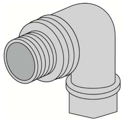
Fig - Fig. - Abb.- Fig.- Fig.- Φιν.- Obr.- Fig.- Eικ.- Joonis - Kuva - Sl. - ábra - Fig. - att. - Afbeelding - Fig. - Rys.- Fig.- Fig. - Cxema - Obrázok - Sl.- Fig. - Sl. - Fig. - Resim - Man.
1
2
3
4
INDEX
1.APPLICATIONS 1
2. PUMPABLE LIQUIDS 1
3. TECHNICAL DATA AND LIMITATIONS OF USE 2
4. MANAGEMENT 2
4.1 Storage 2
4.2 Transport 2
4.3 Weight and dimensions 2
- WARNINGS 2
- INSTALLATION 3
- ELECTRICAL CONNECTION 3
- START-UP 3
- PRECAUTIONS 4
- MAINTENANCE AND CLEANING 4
10.1 Cleaning the suction filter 4
10.2 Cleaning the NRV 4
- TROUBLESHOOTING 4
12.GUARANTEE 5
WARNING

Read all this documentation carefully before installation:
Take out the plug before any intervention. Absolutely avoid dry operation: the pump must be activated exclusively when it is immersed in water. If the water is finished, the pump must be deactivated immediately, taking the plug out of the socket.
Protect the electropump against inclement weather.
The pump is equipped with a thermal overload safety device. In the event of any overheating of the motor, this device automatically switches off the pump. The cooling time is roughly 15 to 20 minutes, then the pump automatically comes on again. If the overload cutout is tripped, it is essential to identify and deal with the cause of the overheating. See Troubleshooting.
1. APPLICATIONS
Self-priming centrifugal jet pumps with excellent suction capacity, even when gas is present in the water. Particularly indicated for water supply and pressure boosting in farmhouses. Suitable for small farming and gardening applications and for general hobby activity. Thanks to their compact and handy shape, they are also used for particular applications as portable pumps for emergency situations such as for drawing water from tanks or rivers.

These pumps cannot be used in swimming pools, ponds or basins where people are present, or for pumping hydrocarbons (petrol, diesel fuel, combustible oils, solvents, etc.) in accordance with the accident-prevention regulations in force. They should be cleaned before putting them away. See the chapter "Maintenance and Cleaning".
2. PUMPABLE LIQUIDS
Clean, free from solid bodies or abrasive substances, non-aggressive.
| Fresh water | ● |
| Rainwater (filtered) | ● |
| Clear waste water | ○ |
| Dirty water | ○ |
| Fountain water (filtered) | ● |
| River or lake water (filtered) | ● |
| Drinking water | ● |
Suitable
Not suitable
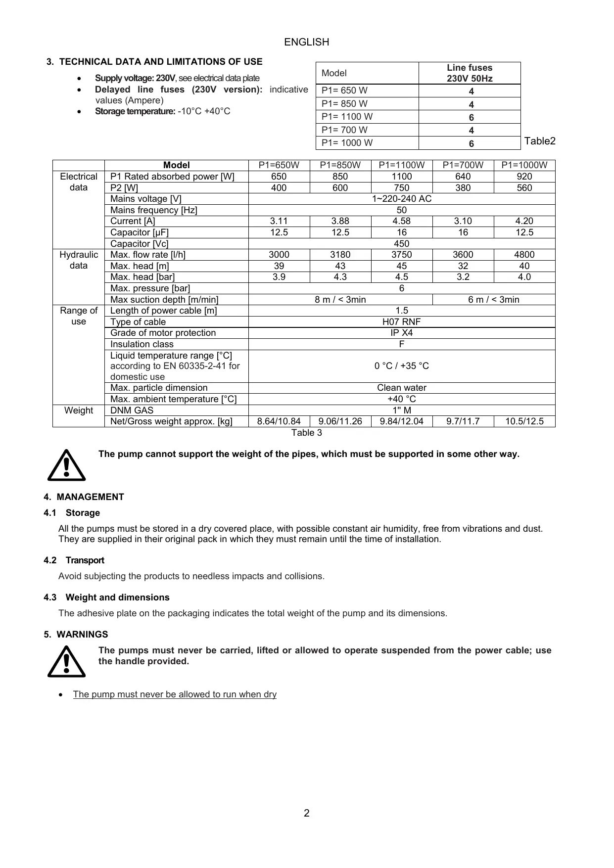
3. TECHNICAL DATA AND LIMITATIONS OF USE
Supply voltage: 230V, see electrical data plate
- Delayed line fuses (230V version): indicative values (Ampere)
Storage temperature: -10^ + 40^
Table2
| Model | Line fuses 230V 50Hz |
| P1= 650 W | 4 |
| P1= 850 W | 4 |
| P1= 1100 W | 6 |
| P1= 700 W | 4 |
| P1= 1000 W | 6 |
Table 3
| Model | P1=650W | P1=850W | P1=1100W | P1=700W | P1=1000W | |
| Electrical data | P1 Rated absorbed power [W] | 650 | 850 | 1100 | 640 | 920 |
| P2 [W] | 400 | 600 | 750 | 380 | 560 | |
| Mains voltage [V] | 1~220-240 AC | |||||
| Mains frequency [Hz] | 50 | |||||
| Current [A] | 3.11 | 3.88 | 4.58 | 3.10 | 4.20 | |
| Capacitor [μF] | 12.5 | 12.5 | 16 | 16 | 12.5 | |
| Capacitor [Vc] | 450 | |||||
| Hydraulic data | Max. flow rate [l/h] | 3000 | 3180 | 3750 | 3600 | 4800 |
| Max. head [m] | 39 | 43 | 45 | 32 | 40 | |
| Max. head [bar] | 3.9 | 4.3 | 4.5 | 3.2 | 4.0 | |
| Max. pressure [bar] | 6 | |||||
| Max suction depth [m/min] | 8 m / < 3min | 6 m / < 3min | ||||
| Range of use | Length of power cable [m] | 1.5 | ||||
| Type of cable | H07 RNF | |||||
| Grade of motor protection | IP X4 | |||||
| Insulation class | F | |||||
| Liquid temperature range [°C] according to EN 60335-2-41 for domestic use | 0 °C / +35 °C | |||||
| Max. particle dimension | Clean water | |||||
| Max. ambient temperature [°C] | +40 °C | |||||
| Weight | DNM GAS | 1" M | ||||
| Net/Gross weight approx. [kg] | 8.64/10.84 | 9.06/11.26 | 9.84/12.04 | 9.7/11.7 | 10.5/12.5 | |

The pump cannot support the weight of the pipes, which must be supported in some other way.
4. MANAGEMENT
4.1 Storage
All the pumps must be stored in a dry covered place, with possible constant air humidity, free from vibrations and dust. They are supplied in their original pack in which they must remain until the time of installation.
4.2 Transport
Avoid subjecting the products to needless impacts and collisions.
4.3 Weight and dimensions
The adhesive plate on the packaging indicates the total weight of the pump and its dimensions.
5. WARNINGS

The pumps must never be carried, lifted or allowed to operate suspended from the power cable; use the handle provided.
The pump must never be allowed to run when dry
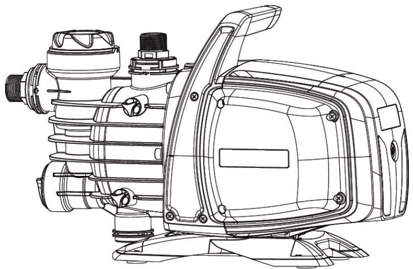
6. INSTALLATION

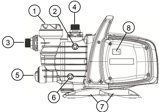
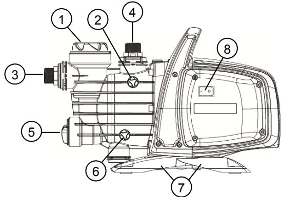
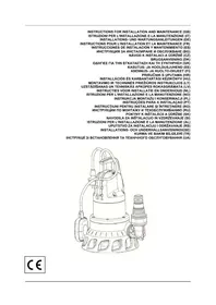
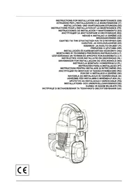
1 Pre-filter
2 Vent cap
3 Swivel suction connection
4 Swivel delivery connection
5 Integrated non-return valve
6 Drainage cap
7 Vibration-damping rubber feet
8 ON/OFF, P1=850W / P1=1.100W / P1=700W / P1=1000W
The pump must be installed in a place protected from unfavourable weather conditions, and with an environment temperature not higher than 40^ .
The pump is provided with vibration-damping rubber feet, but in the case of fixed installations it is possible to remove them and provide anchorage to the base (7).
Do not allow the pipes to transmit excessive forces to the pump inlets (3) and (4), to avoid creating deformations or breakages.
It is always good practice to place the pump as close as possible to the liquid to be pumped. The pump must be installed only in horizontal position.
The pipes must never have an internal diameter smaller than that of the pump inlets; on intake, the pump is provided with a filter (1) and a non-return valve (NRV) (5).
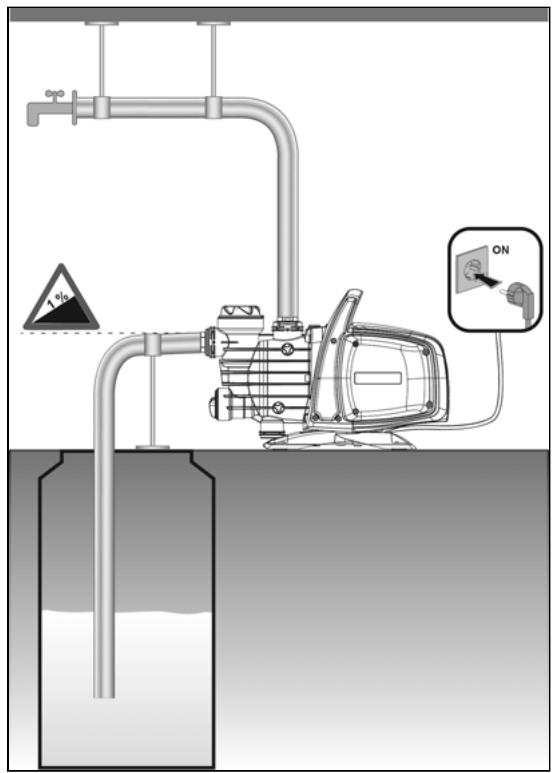
For suction depths of over four metres or with long horizontal stretches it is advisable to use an intake hose with a diameter larger than that of the intake aperture of the pump. To prevent the formation of air pockets, the intake hose must slope slightly upwards towards the pump. Fig.2
If the suction pipe is made of rubber or flexible material, always check that it is of the reinforced vacuum-resistant type to avoid shrinkage due to suction.
In case of a fixed installation, it is recommended to fit a closing valve on both the suction side and the delivery side. This allows closure of the line upstream and/or downstream from the pump, useful for service and cleaning operations or for periods in which the pump is not in use.
The pump has a rotating inlet and outlet to facilitate installation (3) and (4)
In the case of flexible pipes, if necessary, use a bend fig. 1 and the gardening kit composed of a PE pipe and a kit of couplings with lance. These are not supplied, but can be bought separately. In the case of very small dirt, as well as the integrated filter (1), it is recommended to use a pump inlet filter fitted on the suction pipe.
- Do not subject the motor to excessive starts/hour; it is strongly recommended not to exceed 20 starts/hour.

The diameter of the suction pipe must be greater than or the same as the diameter of the pump inlet, see Table 3.
7. ELECTRICAL CONNECTION

Ensure that the mains voltage is the same as the value shown on the motor plate and that there is the possibility of making a good earth connection. Follow the indications on the technical data plate and in this manual, table 3.
The length of the power cable on the pump limits the installation distance, if an extension is required, make sure that it is of the same type (e.g. H05 RN-F or H07 RN-F depending on the installation) see tab.
8. START-UP

Do not start the pump without having completely filled it with liquid, about 4 litres, until it comes out of the air vent cap (2).
If the water supply is finished, take the plug out of the socket immediately and switch off the pump. Avoid dry running.
- Before starting, check that the pump is properly primed, filling it completely, with clean water, through the filling hole, after having removed the filling cap of the transparent filter (1), with your hands or with the appropriate tool provided. At the same time open the vent cap (2) to let out the air. This ensures that the mechanical seal is well lubricated and that the pump immediately starts to work regularly. Dry operation causes irreparable damage to the mechanical seal.
- The filling cap must be screwed on accurately until it stops (1), as must the vent cap (2).
- Insert the plug of the power cable in a 230 V power socket. Attention! The pump motor will start immediately, the water will start to come out after a maximum time of 3 minutes, depending on the depth of the water level, in the well or cistern.
- The pump will continue to work and supply water. Attention! Avoid dry running.
- To switch off the pump, take the plug out of the power socket.

In case of problems with the priming, repeat the handling until all air in the suction is disappeared.
9. PRECAUTIONS
RISK OF FROST: when the pump remains inactive at a temperature lower than 0^ , it is necessary to ensure that there is no water residue which could freeze, causing cracks in the plastic parts.
If the pump has been used with substances that tend to form a deposit, or with water containing chlorine, rinse it after use with a powerful jet of water in order to avoid the formation of deposits or encrustations which would reduce the characteristics of the pump.
10. MAINTENANCE AND CLEANING
In normal operation the pump does not require any type of maintenance. In any case, all repair and maintenance work must be carried out only after having disconnected the pump from the supply mains. When restarting the pump, ensure that it has been correctly reassembled, so as not to create a risk for persons and property.
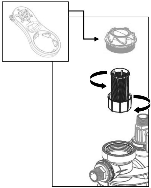
10.1 Cleaning the suction filter
(Fig.3)
- Switch off the electric power supply to the pump.
- Drain the pump, opening the drainage cap (6), after having first closed the gate valves upstream (if present).
- Unscrew the cover of the filter chamber, with your hands or with the appropriate tool provided
- Extract the filter unit from the top
- Rinse the cup under running water and clean the filter with a soft brush.
- Reassemble the filter, performing the operations in inverse order.
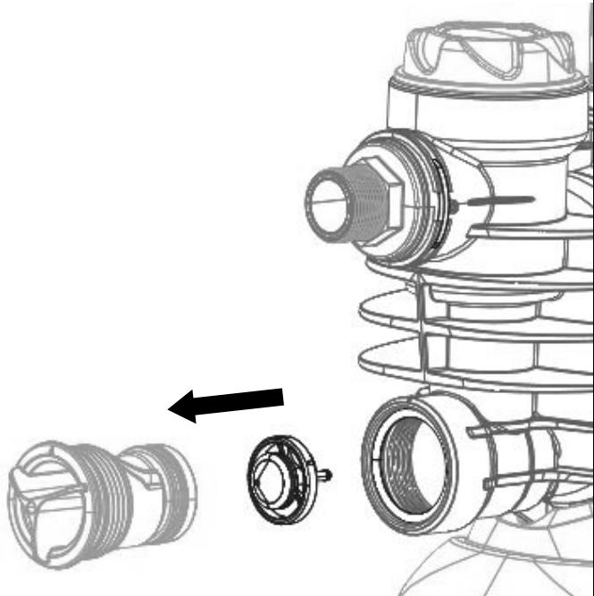
10.2 Cleaning the NRV
(Fig.4)
- Switch off the electric power supply to the pump.
- Remove the cap of the NRV (5) with the accessory provided.
- Remove the NRV check valve and clean it to remove any dirt fig.9
- Assemble the parts, proceeding in inverse order to disassembly.
11. TROUBLESHOOTING

Before taking any troubleshooting action, disconnect the pump from the power supply (i.e. remove the plug from the socket). If there is any damage to the power cable or pump, any necessary repairs or replacements must be performed by the manufacturer or his authorized customer support service, or by an equally-qualified party, in order to prevent all risks.
| FAULT | CHECKS (possible cause) | REMEDY |
| 1. The motor does not start and makes no noise. | A. Check the electric connections. B. Check that the motor is live. C. Check the protection fuses. D. Possible intervention of thermal protection | C. If they are burnt-out, change them. D. Wait about 20 min until the motor cools. Check and eliminate the cause. N.B.: If the fault is repeated immediately this means that the motor is short circuiting. |
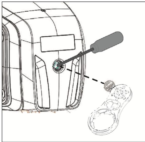
| 2. The motor does not start but makes noise. | A. Ensure that the mains voltage is the same as the value on the plate. B. Look for possible blockages in the pump or motor. C. Check that the shaft is not blocked. D. Check the condition of the capacitor. | B. Remove the blockage. C. Use the tool provided to release the shaft. D. Replace the capacitor |
| 3. The motor turns with difficulty. | A. Check the voltage which may be insufficient. B. Check whether any moving parts are scraping against fixed parts. | B. Eliminate the cause of the scraping. |
| 4. The pump does not deliver. | A. The pump has not been primed correctly. B. The diameter of the intake pipe is insufficient. C. NRV non-return valve or filter clogged. | A. Fill the pump with water and prime it, taking care to let air out by unscrewing the vent cap. B. Replace the pipe with one with a larger diameter. C. Clean the filter and, if this is not sufficient, the NRV. |
| 5. The pump does not prime. | A. Suction pipe is taking in air. B. The downward slope of the intake pipe favours the formation of air pockets. | A. Eliminate the phenomenon, checking that the connections and the suction pipe are airtight, and repeat the priming operation. B. Correct the inclination of the intake pipe. |
| 6. The pump supplies insufficient flow. | A. The suction pipe is clogged. B. The impeller is worn or blocked. C. The diameter of the intake pipe is insufficient. | A. Clean the suction pipe.. B. Remove the obstructions or replace the worn parts. C. Replace the pipe with one with a larger diameter. |
| 7. The pump vibrates and operates noisily. | A. Check that the pump and the pipes are firmly anchored. B. There is cavitation in the pump, that is the demand for water is higher than it is able to pump. C. The pump is running above its plate characteristics. | A. Fix the loose parts more carefully. B. Reduce the intake height or check for load losses. C. It may be useful to limit the flow at delivery. |
12. GUARANTEE

Any modification made without prior authorisation relieves the manufacturer of all responsibility. All the spare parts used in repairs must be authentic and all accessories must be authorised by the manufacturer, in order to ensure maximum safety of the machines and of the systems in which they may be installed.
This product is covered by a legal guarantee (in the European Community for 24 months from date of purchase) against all defects that can be assigned to manufacturing faults or to the material used.
The product under guarantee may, at discretion, either be replaced with one in perfect working order or replaced free of charge if the following conditions are observed:
- the product has been used correctly in compliance with the instructions and not attempt has been made to repair it by the buyer or by third parties.
- the product has been consigned to the outlet where it was purchased, attaching a document as proof of purchase (invoice or cash register receipt) and a brief description of the problem found.
The impeller and parts subject to wear are not covered by the guarantee. Intervention under guarantee does not extend the initial guarantee period in any way.
INDICE
- APPLICATIONI 6
- LIQUIDI POMPABILI 6
- DATI TECHNICI E LIMITAZIONI D'USO 7
- GESTIONE 7
3. TEXHNUECKN DAHHN I OPGAHNUEHEN 3A YIOTPEBA
3axpaHbauo HapexeHne: 230V, BnK nJeHT. Ta6ena c eIeKtpuuecknte daHHN
- Празиелю Линяс c OTNoXeH O DeIcTBn (Bepn 230V):прIMepn cToHocTn (Ampep)
Tempepatya Ha cklaDupaHe: -10^ + 40^
Tabnna 2
| Моden | Проблеситей по Линята 230V 50Hz |
| P1=650 W | 4 |
| P1=850 W | 4 |
| P1=1100 W | 6 |
| P1=700 W | 4 |
| P1=1000 W | 6 |
Tábniça 3
| Моden | P1=650W | P1=850W | P1=1100W | P1=700W | P1=1000W | |
| Данни -"/"/"/"/"/"/"/"/"/"/"/"/"/"/"/"/"/"/"/"/"/"/"/"/"/"/"/"/"/"/"/"/"/"/"/"/"/"/"/"/"/"/"/"/"/"/"/"/"/"/"/"/"/"/"/"/"/"/"/"/"/"/"/"/"/"/"/"/"/"/"/"/"/"/"/"/"/"/"/"/"/"/"/"/"/"/"/"/"/"/"/"/"/"/"/"/"/"/"/"/ | ||||||
| Р1 Номинална консуmpирана мошноct [W] | 650 | 850 | 1100 | 640 | 920 | |
| P2 [W] | 400 | 600 | 750 | 380 | 560 | |
| Мреково наразожения [V] | 1~220-240 AC | |||||
| Мрекова чECTOTA [Hz] | 50 | |||||
| Ток [A] | 3.11 | 3.88 | 4.58 | 3.10 | 4.20 | |
| Конденистор [μF] | 12.5 | 12.5 | 16 | 16 | 12.5 | |
| Конденистор [Vc] | 450 | |||||
| Данни -"/"/"/"/"/"/"/"/"/"/"/"/"/"/"/"/"/"/"/"/"/"/"/"/"/"/"/"/"/"/"/"/"/"/"/"/"/"/"/"/"/"/"/"/"/"/ | ||||||
| Макс. дебит [I/h] | 3000 | 3180 | 3750 | 3600 | 4800 | |
| Макс. наор [m] | 39 | 43 | 45 | 32 | 40 | |
| Макс. наор [bar] | 3.9 | 4.3 | 4.5 | 3.2 | 4.0 | |
| Макс. налаягане [bar] | 6 | |||||
| Макс. дыбочина на засмухвае [m/min] | 8 m / < 3min | 6 m / < 3min | ||||
| Сфера на"/"/"/"/"/"/"/"/"/"/"/"/"/"/ | ||||||
| Дыж. Зхсаньаше "[m] | 1.5 | |||||
| Вид кабел | H07 RNF | |||||
| Стоен на зашита на двигателя | IP X4 | |||||
| Клас Истолаця | F | |||||
| Темпeparатерен обхbat на т教职工代表大会 [°C] съласно EN 60335-2-41 за сbitabella уnotpeba | 0 °C / +35 °C | |||||
| Макс. размер на частцITE | Чinctа ВODa | |||||
| Макс. Temпeparатура на okолнatable среда [°C] | +40 °C | |||||
| Тerglio | DNM GAS | 1" M | ||||
| Тerglio.neto/Бруто приобл. [kg] | 8.64/10.84 | 9.06/11.26 | 9.84/12.04 | 9.7/11.7 | 10.5/12.5 | |

Iomnata He Moke da n3dpbxN TeXecTTa Ha Tpb6nte, KOrTO B IpOTnBeH CnyaH Tp8Ba Da ce noHece.
4. CTONAHNCBAHE
4.1 CbxaheHne
Bcunn nnon Tp8bda da ce cbxpanBaT B 3akpnto, cyxo macto, no Bb3MOXHOCT C NOCTOHNHBA NpaXHOCT Ha Bb3dyxa, 6e3 Bn6paunn npax. DocTabrT Ce B opunnaHa ONaKOBka, B KOJTO Tp8bda da OCTaHaT DO MOMENTa Ha MOHTaKa.
4.2 TpaHcnpot
I368raTe da noJlaRaTe npOyKtTe Ha HeHyKHi ydApn n C6bCbu.
4.3 Terno npa3mepn
IeHTnFkaUHnHnT CTnkep, nocTaBeH Bbpxy onaKOBkata, CbDbpxka yka3aHne 3a o6to Tergno Ha eNektpueckata NOMna n 3a HeHHte pa3mepn.
5. ПЕДУПЕЖDEHЯ

Iomnnte Hnkora He Tp6Ba Da ce TpaHcnpOpTnpaT, NOBnurat Nnn NyckaT B deiCTBne, OKaueHn 3a 3axpaHbuaa Ka6en, n3NoJ3BaIte CneuHaHaTa dpbkka..
- Помпа ТИКORA He TРЯБа Да ce octabда paBOTи Ha cyxo.
6. MOHTIPAHE
1IpeBapnteIenФЛТьр
2 N3nyckaTeJHaTana
3 OpneHTnpyema BCMykaTeJIHa Bpb3ka
4OpneHTnpyema HAnopHa Bpb3ka
5 INHTerpnpaH HeBb3BpaTeH KJIanaH
6 Tana 3a n3ToUbaHe
7 Tymeni Kpaeta cpeu Bnbaun
8 ON/OFF, P1=850W / P1=1.100W / P1=700W / P1=1000W
EneKtpueckata nomma Tpr6Ba da ce HnCTaInpa Ha mAcTo, 3aunTeHO ot He6laonpnaTHn aTMocΦepHn ycNoBn I TeMnepaTpa Ha OKoHaTa CpeDa, He no-BuCoka ot 40^
Помпае санбдени Крачета Сршу Вибраци, НВ Слунай НфИКсирал MOHTаж И Вьзмохно ДА ГИ Ппeмaxhte Ида пeдвидпе ankeрно зхвашие на HOseша оCHOBA (7).
I368aBaiTe Tp6bTe Da IpeDaBAt N3BbHpeDn YcHnna KbM OTBopnte Ha nomnata (3) n (4), 3a da He ce c63daBat deΦopMaun nn ChynBaHn.
BnHa n e no-Do6pe nomnata da ce MOHTnpa 6n3o do 3xaPbHbHeTo C B0da.
Ja ce MOHTnpa cAmO B XOpn3OHTaJIHNO NIOJoxHeNe.
Tp6bTe He Tp6Ba HnKOra da nMaT BtpeWeH dAmeTbp, No-MaJIbK OT To3n Ha OTBOpTe Ha eNeKtpueckata nomna npn BCMykaTeJIHaTa Tp6ba NOMnata e Cha6deHa C c fInTbp (1) n HeBb3BpaTeH Klanan (HBK) (5).
IpootateuTe Tnavatia aTio tic kaipkeouvhkec.
PpOToaia aTou utepopotwn. H avTlia diathei eTepuikn TPOoTaia kivtnnpa. Ee TepittwoeVExoEvnc uTephemuavonc tou kivtnpa, n TPOoTaia kivtnnpa oBnvei tv avTia autouata. O xpovoc yusns eivai nepinou 15-20 aeTTa, meta atro ta otioia n avTia gavavabei autouata. Meta tynv eteuaon ts npootaoia c kivtnpa anaiteitai auotnpa va avaZntnoTe tnv aiia ka va tvn eoieiTE. EuubouLeuteita tv Avzntnon Blawv.
1. EΦAPMOΓΕΣ
Duyokvpikeavtiee yekaaou autopatnc kkkivnongse Béltiotek avapotntes akopa kai napouia aepioxou ubaoc. Evbikvutai idaitepa yia tnv tropobooia vepou kai tnv diatnpnntc nies paeqsc. Katalnaegyia yewpyia mikpncs ektaanc oaxavoknptous kai yia kntoupikn, ektake s okiakns xphans kai xoTt ev YEVEI. XApn oTO oumuayec kai euxpnato oxima npov va xpnoiotoinoov etianc wspntcs avtles c Tepittwoeic ektaKTNS avayknos otiwas avlnon neipu an noTataia.

Oi avtaic autc cev tntpctetai va xnpoiipotoinoouv oe triivecs, ean, n deqaevec me npouia atouwv, nyia tvn avtianon ubpoyovavpakwv (bevcivn, pertpeiaio, kaoueiaia, diautec, kA). ouuva m TIC KEIVECS DIATAEIG TPOANPS CTUxNmuatWv. PIV Tc aTOnkueoTe 0a nTAV KALO VA epiuvnoTe mia qaoyn ia tov kaopapioo touc. BLTE Kepalao "Sigma npnon kai Kaopipocos".
2. ANTAHsIMA YTPA
2. SIURBIMUI TINKAMI VANDENYS
9. VOORZORGSGMAATREGELEN
- WYKRYWANIE USTEREK 89
- GWARANCJA 90
OSTRZEŽENIA

Adequado
Nao adequado
3. DADOS TECNICOS E LIMITAÇÖES DE USO
- CΦEPbI PnIMHeHnI 101
- IPEKAYIBAEMbI E KIaKOCTN 101
- TEXHnueCKNE DAHHbIe I OPGAHUeHnB 3KcPJIyATAuN 102
- 3KcPJIyATAUJRA 102
4.1 CknaIropOBaHne 102
4.2 TpahcnpTnpOBka 102
4.3 Bec npa3mepbl 102
- IPEyIpeXeHn 102
6.MOHTEX 103
7. 3JIeKTPnueCKOE NOJKnIouyehne 103
8. 3Anyck 103
9. IPEIOCTOPOXHOCTN 104
10.TEXHNUECKOE OBCJUYKUBAHNEI YNCTKA. 104
10.1 Ouchstka dnilbtpa BCacbBaHna 104
10.2 YIcTka NRV 104
PpeoXpaHnTe n3eYOnOT mIshnX yapOB I TOJyKOB.
4.3 Bec npa3mepbl
HakneiKaHa ynaKOBKe yka3bIbaeT 06uN BEc 3NeKtpoHaCoCa n erO pa3Mepbl.
5. ПЕДУПЕЖDEHЯ

HacocbI HNKOrda He DoJXhbl nepeBO3ntbcra, NOHMAtbCRA JINB KBIIOUaTbCRA B NOBeHHom COCToHHN, NcNoJIb3yra Ka6eJIb PNTAHNA, NcNoJIb3yIte CneuaIbHyO pyKy.
Hacoc HNKoIa He IOnKeH pa6oTaB BCxyIO.
6. MOHTAK

1PpeBapnteHbHbIΦnIbTp
2 PpO6ka cnYcKa
3OpneHTnpyEmoe coeHHeHne BCaCbBaHnA
4OpneHTnpyEmoe coeHHeHne npaun
5 BCTpoEHhI HeB03BpaTHbI KJanaH
6 PpO6Ka cNIBa
7 Pe3nHObIe Bn6poracIue HOKNI
8 ON/OFF, P1=850W / P1=1.100W / P1=700W / P1=1000W
3JIeKToHaocO DoJIxKeH yCTaHaBnBaTbCra B MeCTe, 3aIuIeHHOM OT HeNOrOdbI N TempepaTypoi OkpykaHoue CpeDbI He BbIe 40°C.
Hacoc obopydoban Bn6poraczumn Onpamn, HO B Cnyuae HepehoCHoY cTaHO MOnxHO ChrTb IN npedymotptb KpenlneHne K onOpHomy OCHOBAHIO (7).
I36beraTe nepeaun n36bIToUHOrO yCnIny OT Tpyo K ycTbAm Hacoca (3) n (4), YTO6bl He co3daBaTb deOpmauN nnnoJIOJOMOK.
HEn3MeHNo XopoOIM npaBnIOM YBnETCaYcTaHaBnBaTb HaCoc KAK MOxHO 6JInKe K nepeKaunBaemoy XnDkoCTn.
HacocdoJxehbItb yctAHOBHeN NCKJIQUHTeJIbHO B TOpN3OHTaJIbHOM NOJIOXKeHm.
Tpy6bI HNKOrda He DoJIxHbI IMeTb BHyTpEHHN DnAmTeP MeHbSe, Yem yctbA 3JIeKTPoHaCoca N BCacbIBaHnHaCoCa, Hacoc obOpydoBaH qnlbTpom (1) n HeBO3BpaTHbIM KJIanaHom (NRV) (5).
IpybHbBcAsbHaHn, IpeBbHaOeYtebpe MeTpA, INI pRn HAnuN DInHHbIX TOpN3OHTaJIbHbIX OTpe3KOB peKOMeHdyetc NcNoB3OBAbT py6y BCacbHaHn C dNaMeTpOM, BoNbUIM dNaMeTpA BCacbBaHOeO OTBepCTnA 3JIeKtpoHacocA.Bo n36exJaHne O6pa3ObAHn BO3dUshbIX MeKOB BO BCacbBaHOeM Tpy6oPBODe ppeDyCMOTpeTB He60lbWOn POnbem BCacbBaHOse Tpy6bIB CTopoHy HacocA.Pnc.2
Ecni Tpy6a BCacBHaHn BblIOJIHeHa n3 pezHHb IIN rIbKOrO MaTePnaJa, Bcerda npOBepRrTe, YTO OHa yKpeJIeHHoro Tnna, BbldeXnBaIOUeBO BakyyM, YTObI N36ExKaT cyKeHm np BCacBHaHN.
B clyuae HenepeHocHoi yCTaHOBKn peKOMeHdyETcM OHTnPOBaT KJIanaH 3akpyITn KaH Na CTOpOHe BCacbIBaHHa, TaK n Ha HapOpHoi cTOpOHe. 3TO N03BOJraT 3AkpyBaT JINHNIO nepeH hAcOCm IJN NocIe Hero, YTO Tpe6yETcP npi npoBeDeHnn Texo6cnykBaHnry n OouCTkn IJN B cLyuae HeNCNoJIb3OBAHnry HAcoca B TeueHne OnpeJeHnHO nepnoJa. Hacoc Oshauen BpaauaUoImCRA XoIDom n BbIXoDM dJa ObJeUeHnY cTaHOBKn. (3) n (4)
B cnyuae ⅢnHeo6xOIMO, nCnONb3OBaTb KOJeHO pnc.1 IN KOMnIeKT caIOBOcTBa COCTOHT n3 ⅢnHaHROB I3 nKOMnIeKT C hakoHeuHkOM He NoCTabJIeTcR, IN HUxHO NOKyNaTb OTDeJIbHO.
B npucytbnu 3arpa3neHn He6oIbux pa3mepOB, peKOMeHdyetc IcNoIb3ObaTb, NOMMO INTerpnpobAHHOfNtpa (1), BxOHN O Hacoca, MOHTnpOBaHHb Ha IJNaHr BCacbBaHn.
He noDBepraTe DnBraTeJIb n36blTOOHMy KOJIueCTBy 3anyCKOB/acyoB, peKOMeHdyetcR He npebbIaTb 20 3anyckOB B yac.

ДиamEp Tpy6bl BCacbIBaHnЯdoJIKeH 6bITb 6OJIbWe NIIpaBhbIM, YemДиamEp yCTbY 3JIeKtpoHaocca,cm.Ta6JInuy 3.
7. 3ЛЕКТРИСЕСКOE NOДКЛЮЧЕНЕ

He BkIIOuAte HAcOC He 3aIIOJIINB erO IIOJIHOCTbIO XnIDKOCTbIO, OKoIIO 4 JInrPoB, NOKa He BbIeT HApJy BO3dUx n3 cnYcKa (2).
Ecnn nctountc rnnpablnueckn pecypc, HemeIeHNO OTOeHNHTe BnNky, BbIKNoHNB hacoc. IpeDorBpaaaiTe pa60ty 63 BObl.
- Ipeed naujom nycka npobepte, yto hacoc noHocbTo 3anpaBnE BDOi, oBeceuBna ero noHoe 3anonHeHne uCTOn BDOi, uepe 3neuaIbHoe OTBepCTne, nocne ChTnKpbIuKn 3anpaBkn npO3paHoro fInIbTp a (1), pykamn nn npn nomoun nDxOJaero IHCTpyMeNTa B KomPJIeKeTe. OTKpoIe OndHOBpeMeHHo np6ky cnycka (2) dny BbIycka Bo3dyxa. DaHna onepaunr AblraTc Upe3bUaHaNo BaxHoJ dny XopoWero fYHKUONHOpOBAHn HACoca. BaxHo TaXke, yTO6bI mexaHueckoe yNIOtHeHne 6bINo xopoIo Cma3aHO.
Функционироване BCуху БeDET K HeONpaBIMbIM NOBpeЖденяm MexaHueCKOу yNIOTHeHЯ.
PUCCKN
- Побку заразвк следует вовь за кртуть на место до остановки (1),а тarkе за кртуть побку спунская (2).
- BCTaBnTb BnJIky Ka6eIy PtAnHry B po3EtKy PtAnHry 230 B. BHMaHne! IaBraTeIb HacOca HeMeIeHHO 3apabOtaet, BOda Nauchet BbIXoDnTb CnYCTra MaKcIMyM 3 MInHyTbI, YTO 3aBNCIT OT rIy6uHbI ypOBHry BoDbI B KOJIoDcE nJIn cNtcepHe.
- Hacoc npoJoxnT pa6oTaB n noDaBaTb BODy. BHMaHne! PpeOToBpaaAte pa6Ory 6e3 BObl.
- Дя OTКлюченя haocota otcoeDHHte BnIky Ka6eJЯ nItaHry.

Ipn HnHn n np6bnem c HanoHHeHnem, noBtOpnte onepaunO, noka Bo3dyx Ha BCacbIBaHn He 6ydet ydaJIen.
9. ПЕДОCTОPOXHOCTN
ОПАСHОCTь 3AMEP3AHЯ: когда насoc оctaetс He Bкноченblm пи Tempepatype Hnke 0^ , Heobxodmo ybeintbcy,чTOВнemнет OCTaTKOB BObl, KOTOpble пи 3amep3AHIN MOryT npnbectn K Tpeunham Пл actNKOBbIXЧаст。
EcnHacoc nCnOJb3OBaJIcra CBeIeCTBaMn, KOToPbIe IMeIOT TeHdEHNIO K OTNoXeHNIu INC XNOpIPoBAHHoB Odoi, ONOJIoCHNTe erO nOcIe NcNoJb3OBaHnra CNJbHO CTpye BODbl, YTObI bN36eKaTb fOpMnPoBAHnra OcaJaNtOJIOKeHni, KOToPbIE CHNXaIOT 3KcNJyataUOnOHhIe XapakTepeNCTIKn HAcOCA.
10. TEXHnueCKOE OBCJyKINBAHNE N CNTKA
B HopmaJIbHOM pa6oYem peKIme 3JIeKTPoHAcOC He hyKJaETc8 B KaKOM-JIb6o TexHnueCKOM o6CnyKnBaHH. B JIObOM cIyuae BCE pa6oTbI n peMOHTy IN TexHnueCKOMy o6CnyKnBaHHIO DOJIKHbI OcyIeCTBnTbcra NocIe OTCoEiHHeHHa Hacoca ot cEtN 3JIeKTPoHITAHINr. Quando si fa ripartire la pompa, assicurarsi che sia stata rimontata a regola d'arte, per non create pericolo a cose e persone.
10.1 OuicTka qnIbTpbaCacbBaHna
(Cxema 3)
- OBeCTOuHTb HaocC.
Cnntb BODy,OTKpbIB npo6ky CnBa (6), 3aKpbIB npeBapNTeJbHO 3acNoHKn nepei Hm (ecnn NMeHTc).
OTBnHTnte KpbIuKy KaMepbI nJbTpa, pykamn nn CneuaNbHbIM HNCTpyMeHTOM B KOMJIeKTe. - BbInbTe uepe3 Bepx 6Jok Hacoca.
- Onolochite ctaKaH NOI cTpye BODbl OunchTe pNlbTp npn NOMOUn MRAKOn 1eTKn.
BHObco6epnte 1nJIbTp, BbIOJNHB onepaunn B o6paTHoI nocJeIOBaTeJIbHOCTn.
10.2 Ynctka NRV
(Cxema 4)
- ObecToUHTb HaCoc.
- CnHmIte npo6ky NRV (5) npi nOmoI npHaJIeJxHOCTN B KOMJIeKTe.
- ChINMITE CTONOPHbI KIaIaN NRV uOcntte ero ot 3arp3HeHn pnc.9.
- Cobepnte yactn MeToDOM o6paTHoN c6opKn, B o6paTHoN nocJeDoBaTeJbHOCTN.
INNEHÄLLSFÖRTECKNING
- ANVÄNDNINGSOMRÄDEN 126
- VÄTSKOR SOM KAN PUMPAS 126
- TEKNISKA DATA OCH ANVÄNDNINGSBEGRÄNSNINGAR 126
- HANTERING 127
3axnataHacoc BiHeratNBHO BpNBy HenoroTa iHxnpoDnHex yBnI.
3axnct BiD nepeBaHTaxeHH. Hacoc yCTaTKOBaHn abapiHm TENJIO-BMIMKaayem DBNyHa. Y BnnaIky neperpiBaHH nBnryHa abaiHn BmNKauch BTOMaTHUHO BMIMKaC HAcOC. DnOxONoJKeHH NDBnryHa Heo6XiIDHO np6bn3Ho 15-20 XB., nicra YORo HACOC 3HOBy BMKAcTbcA ABTomatuHNo. Picra AKTNaCiabapuiHoro BMIMKaua Heo6XiIDHO Oob'3KOBO BnABNTu Ta ycHyTu II npuHny. DInB. "Piouk HenonlaDOK".
1. 3ACTOCYBAHH
CtpymeHeBO-BiDcHrPoBI CAMOBCMOKTyUOHi HAcOci 3 BiIMHHMn BCMOKTyBaJIbHMn XapaKTePncTnKaMm, B TOMy ChcnI i B npncyTHocTi ra3oBaHOI BOiN. Ppns3HaueHl 3okpeMa IJRA BOIOIOCTaAHHr Ta NiIBuIeHNr TnCKy B JKTIOBHX 6yDnHKax. MoKyTB BVkOpNCTOByBaTnCra IJr 3poSeHnra Ta IOniBy ropOIB Ta caIDB He3Haunx po3MpIB, B abApIHnx CNTyaIrx NobYTOBO rPBNa Ta pObit IJr Do3BInnra B cIJOMy. 3ABdKn KOMPAkTHni, 3pyHni IJr IepemIeHNr foPmI ci HAcOci 3actOCBOYtBcA IJr pi3HnX ppi3HaueHb, B TOMy UcNci I Jk abapiiHi nopTaINBHI HAcOci IJr BnKAUYBaHHR BoDN 3 pe3epByapib abo BOIoMnI.

Li Hacocn He MoXHa BnKOpNCTOBvBaTn B 6aceHax, CTabkax, BDOOMnIax y npncTyHOCTi IHOeJ, a TaKoX dIy NepeKauyBaHH naNBHX Ta rOpOuNX MATEpiaJIb (6eH3nHy, DN3eJIbHoro NaIBa, rOpOuNX Macen, po3UnnnHKnB Ta iH.) 3rIHO BiNobIDnIX Hopm 3 TexhIKN 6e3neKN YHHORO 3aKohODaBCTBa. PicIy IX BnKOpNCtAHH, nepeD TIm, JNKoNactn Ix Ha 36epirAHH, peKOMeHNyCTbcra npOBecTI petelbHn OrIyad Ta uNcTKy. DInB. po3dIN "DorIy Ta texhIyHe o6CnyROvBaHH".
2. TINPIIDINHДJIANEPEKAUYBAHHJ
UncTa, 6e3 TbePdAnx afo abpa3nBnX YacTnH, He arpecsInBa.
PpnaHaueHn
He npn3naeHn
3. TEXHIYI XAPAKTEPNCIKI TA EKCPIIYATAUJIHI OBMEXEHHA
- Hanpyra XINBJIeHn: 230 B, INB. nacnpOtpHy Ta6JIuCy
- LiHiHi 3anobixHHNKm 3aTpumKoO di (Bepci 230 B): iHdkatnBhi 3naeHHra (Amnepe)
- Tempepatya 36epiranha: BiD -10°C Do +40°C
Tabella2
Hacoc He B 3Mo3i yTpmyBaTn Bary Bcix Tpy6onpOboiB, cIid 3a6e3neHTn yTpmaHHra Tpy6onpOboiB iHsIM Cnocobom.
4. ПИИНДТТА 3БЕПIGАHHA
4.1 PnHraTHa 36epirAHH
Bci Hacocn cnid 36epiratn B cyxomy 3akpntomy npimiuheHni, 3i ctaJIM pIBhem BOJorOCTi, 6e3 Bi6paui Ta nny. Hacocn noctabJIyIbCBy BIDIOBIDHI ynaKOBUci, B kii ix cnld 36epiratn DO MOMENTy yCTaHOBKn.
4.2 TpaHcnoptyBaHHa
Bepertn BiD ynapiB ta 3tKHeHb.
4.3 Bara ta po3mipn
Ha ynaKOBky haHocntbca KneIka Ta6JIuUka, Ha kIy BkA3aHI 3araIbHa Bara HAcOcy Ta Ioro po3Mipn.
5.3ACTEPEXEHH

3a6bOpHaeTbcnpeB03ntn, nepemiuyBaTn, niHimaTu a6o ekcnnyatyBaTu Hacocn y niBiweHomy CTahi, BnKOpNCTOByUOuN dIy cIx diI Ka6eIb XNBJIeHHra; KopncTyBaTncdIy cIboro BiIDNOiHOIO pykoio.
3a6bopohraetbca poroTa hacocaa BCyxy".
6. YCTAHOBKA
1 PonepeDniΦiNbtp
2 Cnysckna npo6ka
3ПоворOTHE 3'ЕДиHAHHЯ BCMOKТУВаHHЯ
4 NOBOPOTHe 3'EDHaHnHaNoDaU
5 lTeIrpObaHn HEnOBOpOTn (3anipHn) KlaNaH
6 Cnysckna npo6ka
7 Antbib6paui Hi rymoBi HiKki
8 ON/OFF, P1=850W / P1=1.100W / P1=700W / P1=1000W
EneKtpoHAcoc cIid BCTaHOBHTN B cyXOMy, 3axuIeHOMy BiD HeaTINBHorO BnINBy HEnorOOn Ta iHxN x npipOdHnx YBnI npimiuHHi 3 TempepaTPOIO He BnIe 40^
Hacoc yctaTkoBahi anTHiBibpauiHmH iKkAmn, aIe y Bnnaiky noCTiHoi yCTaHOi IX MOxHa 3HrTn i BnKOHaTI φikcObaHe KpInJeHHdo OnOpHOi OCHOBn (7).
YHnKATn HaNmipnHex 3ycnIb 3 boky Tpybo npoBodIB Ha natpy6kn Hacocy (3) Ta (4), 06 He IOnyctntn DeOpmaucii Ta NOsIKoDxKeHb.
3aBxnn peKOMeHnycTbcra BCTaHOBJIIOBaTHn Hacoc kOMORA 6nXyue do Micu3haxOJxHnnepeKaUyBaHOi piDHH.
Hacoc cniD BCTaHOBJIIOBAti TINbKN B rOpN3OHTaJIbHOMy NOJIOXeHHI.
3abopohetbca BnKOpncTahnn TpyboonpoBODiB, BHytpiHni DiAmepr knx MeHne DiameTp yntpy6kiv Do eNeKTPOhacocy Ta Ha BCMOKtBuHaHHa; HACOC ycTaTKOBaHm fIbTpom (1) Ta HeNoBOPOTHM KnaHaHom (HPK/NRV) (5).
Y BUNAOK Ky BCMOKTyBaHHa 3 rIbHn H6JIbSe OOTnpbOx MeTpIB a60 y BUNAOKy DOCHTB BeINKHX BiDCTaHHe NODaHi BROP3OHaJIbHOMy HAnpRMky peKOMeHNyEcbc BHKOPNCTOByBaTN Tpy6y BCMOKTyBaHHa 3 bIbShm DiAMEtpOM, HIX diametp BCMOKTyBaHOro NaTpy6ka eNEKTPoHAcoccy. 06 3anobirn YTBOpEHNO NOBITPraHx np6ok y BCMOKTyBaJIbHI Tpy6i, cIq npeJbauHn He3NaUHn IOnTnBnHn HaxNJ BCMOKTyBaJIbHOI Tpy6n B HanpMky Do eNEKTPoHAcoccy. Man. 2 RaKIO BCMOKTyBaJIbHa Tpy6a BnroTOBnHa 3 rymn a60 iHsoro rHyckoro MaTepiany, cnid 3abXdN nonepedhbo nepeBiprtn, 06 BOHa HaJexkana do NoCInleHORo BAKyUMHO-pe3nCTeHTHOrToTny, 06 3anobirn 3ByjKeHHIO nn diEco BCMOKTyBaHHa.
Ppi fikcobaniy yctahOBu peKOMeHdyETbCMAOTyBatn 3anipHnn Klnapan Jk 3 bOKy BCMOKTyBaHHa, TaK i 3 bOKy npda.
Lcdo3BOJNTB nepeKpTN NiHIO Bnue abo HnXue BiD HacOca, Ioo 3pyuHNO dJa BVKOHaHH po6i T 3TexHiHoro
06cIyROByBaHHa, DOrJIy Da Tu NcTKn, a TaKoX y pa3i BnuaKIB, KOJI Naoc He BVKOpNCTOByETbcra.
Hacoc yctaTkoBAHn IOBOpOTHMn BxIDHMn Ta BxXdHMn 3'EDHaHnRMyn, IIO cnpOuye Ioro yCTaHOBky. (3) Ta (4).
Pn BnKOpNCTaHHI rHyuKnx Tpy6 npn Heo6xIDHocTi cKOpNCTaTncs KaIIHOM, Ma1.1, Ta CneiaJbHm Ha6opom, 0cKnadaeTbc3 IPE Tpy6 Ta pitiHrib; BOHN He NoCTabJIOTbc8 B KOMJIeKti, aJe IX MOKHpNiD6aTn DoDAtKOBO.
Y BnnaKny HaraBHOCTI DomiUOK dyJke MaNOro po3Mipy peKOMeHdyE'Tbcra, KpIM iHTerpoBaHoro fInbTpY (1), BnKOpNCtOByBaTn fInbTp Ha BxOdi B HAcOC, kAn CnId MoHTyBaTn Ha BCMOKTyBaJIbHi Tpy6i.
- YHnKaTn 3aHaITo Yactnx BmKaNb IbNpyHa Ha npOTa3i rOuHH, HactiHo peKOMeHdyETbcr He nepeBnUyBaTu 20 3anyckiv/roDInHy.

Дiametpr Tpy6n BCMOKTyBaHHЯ NOBHHEN 6yTN 6iNbWM a6o DOpIBHOBaTH iAmetpy NaTpy6ka OTbopy eNeKtpoHaocCy, nVB. Ta6JIuIcI 3.
7. ENEKTPNHY NIKNIQUEHNA

IpekoHaTcB TOMy, 0o Hanpyra Mepekix KINBHeHH BIDNOiAde Bka3aHHi Ha nacnopThi Ta6nUci DnHyHa, a TAKOX nepebipNTM OMOJIbICt b HadiHORO 3a3eMHeHH. DOrpIMyBaTnc Bka3IBOK, 3a3HaueHnx Ha 3aBOcbKII Ta6nUci Ta B Ta6nUci 3 daHoro TexHCHORO noc6Hnka.
Довжина Kaбелю КИВЛЕнну Habocу obmexky BiDcTaHb Ioro yctaHOBKn;В pa3i Heo6xIqHOCtI BnKOpIcTaNHH NOIOBxUyBaA nepeBipuTu, uOb biN bYB toro x camoro Tny (HaNP., H05 RN-F a6o H07 RN-F 3aJIeXHocTi BiD yCTaHOBKn) dNv. Ta6.3.
8. NOYATOK POBOTN

He Bmikatn Hacoc Do Tux nip, DOKN BiH NOBHCtHO He HANOBHTbcra pIDINHO, Pp6bn3HO 4 NiITpn, DOKN piDnHa He noUHe BntiKaTn Upeez npo6ky dny cnucy nobitpr (2).
Y BnnpaKy BnuepnaHNa BODn CnIe HeraiHo BnTgHyTu BNILky 3 pO3eTK, IIOb BmKHyTu HAcOC. YNkATn po6OTn "BCyxy".
- Ipeed BMnKaHm nepeBipu, 06 hacoc 6yB 3aJntn HaneKHM uHOM uHCTOIO BOHO uee3 BiNobIDHn OTbip, nCJIra 3aJIbHoi npo6Kn npOnyckHoro fIbtpy (1); nepeBipky 3diChIOBaTn BpyHy a6o CneiaJIbHm IHcTpymEtOM, 0u HadaeTbcB KOMJIeKti. Ondoucho 3 cMn BiDpHTn TaKoX cnYCKHy np6Ky (2), 06 BnPyctHn Nobitpy. L'onepaiz HA3BnuAHHo BaxnBa dny 6e3dOrAHHO p6OTo n Hacoca, 06 3aBe3neHTn HaneKHe 3MaUyBaHHa MexaHCHoro yuInbHeHHa. Po6ota "BCyxy" npn3BOIDtB do He3BOpOTHO NOwKOJKeHHa MexaHCHoro yuInbHeHHa.
2.ПсЯцboro сд ретьно зakpyтntи залву npobkydo уnpу (1),якісnyckу npobky (2).
YKPAIHcBA
- BCTaBHTN BuJky Ka6eJIIO JxNBHeHH B po3eTKy MepeXi JxNBHeHH 3 HApIyOIO 230 B. YBara! DnBryH hAcoca yBIMKHeTbCg HeaHIO, BOa NOChne IoDaBaTncg MaKcMym Ha IpOTa3I HAcTyHnx 3 XBuINH, IIO 3aJeKntb BiD rInbHNPiBHa BOIN B KOIoJa3i YN B pe3epByapi.
- Hacoc npoobkntb po6oty i noaay Boi. Ybara! UnkaTn po6OTo "BCxyu".
- 506 BmKHyTn HAcO, CπiD BntaTn BnJIky 3 po3ETKn XnBJIeHHra.

Jkuo BnHKaHb npobem i3 3aJIuBkoH, NOBTOBAtn npokaKy Do Tnx nip, DOKn He 3HnKHe NOBITpHa BCMOKTyBaHHi.
9. 3ACTEPEXHII 3AXOДN
PNI3IK 3AMEP3AHHЯ:якшо haoc 3aJIshaεTbc8 B Hepo6oy cTaHI npi TempepaTypi HnKYe 0 °C, cIiD nepekoHaTncB TOMy, lo B HbOMy Hemae 3aJIshky BoDN, lo npi 3amep3aHHI MoKe NIOJKOdTI NpactMaOBI qaCTINH HaCOca.
Picra Bkopnctaan Haocy dIa BiDeeHn peoBn, kci CxnlbHi Do HakonuYe Ta BiKnaedeh, aO nicra nepekaUbaHH XlOpOBaHO I BoDn NOrO cIiD npOMNTn YNCTOIO BOIO; DJI npOMNBHaHc KcOpNCtATncs CInbHM cTpyMeHem BoDn, 063anobirTu yTBopeHHIO BiKnaedeH, 0o MOkyTb HeratNBHO BpNNHyTN Ha EKCnlyatauiHi xapaKTepnCTNKn Haoccy.
10. Доглад ТАТEXHИЧЕ OБСЛУTOВАВHAнь
Pn HopmaIbHnx yMOBax ekCnIpyataui eJeKtpoHaoc He notpe6ye HiaKoro texHiyHOro 0cbNyROByaHHra. B 6yd-koMy pa3i BcPi pObotu 3 peMoHTy Ta texHiyHoro 0cbNyROByaHHra CnID BIKOHByATn TiMbKn NiCnA BiDKNIOeHHra HAcOCy BiD Mepexi JxNBHeHHra. Ipeed TmM, k3HOBy YbIMKHyTu HAcOC NiCnA texHiyHoro 0cbNyROByaHHra Ta peMOHTy, CnID nepeBipTu, 0o Bin 3iBpaHn HaLeXHM uHHom, 0oB He CTbOpTu Nbe3neuHy cTuaio Dja oc6 ta MaHa.
10.1 Ynctka BCMOKtyBaJbHoro pfIbTp
(Ma1.3)
- BiДКПИЧИТи HAcOC BiД Мepeksi eNeKtpuHOrO XINBJIeHHЯ.
- CnpoKHTn Hacoc, BiDkPmbuIy Iy cBoro 3InBHy np6ky (6); nonepeHbO nepeKpTu 3acInKn paHie no liHii (aKIO MaIoTbc).
Biikpynttn KpnuKy Kaemepn fInbtpy BpyHy a6o 3a DonomoroO cneiaIbHoro IHCTpyMeHTy, 0o HadaeTbcB B KOMJIneKTI.
BntTn3Bepx6Jokfipbtpy. - Помити склянky niД CTpyMeHem npotoчhoI BODи Ta npOuHCTnTи φiNbTp 3a DonomorOIO M'AKOI uITkn.
3HOBy BCTaHOBnTu ΦiJIbTp Ha MiCe, BVKOHABu Bci OINcAH BNUe DII B 3BOPOTbOMy Ioprky.
10.2 YNCTka HNK
(Ma1.4)
BiiKJIIOHITn HAcOC BiD MepeXi eJekTpUHoro XINBJIeHHra.
3Hrtn npobky HnK (5) 3a donomoro o cneiaIbHoro iHCTpymeHTa, 0u Hadaetbcra B KOMPNeKTi.
3HЯТи HENOBOPOTHn (3aipHn) KJanaH HPK TaNoCHNTiN Ioro, MaI.9
BukohatmOHTaxy 3bOpOTbOMy npaKy.
11. NOUK

Ipeed TmM, kP03nouHaTn noSyk HenoJaDok, Heo6XiDHO BiD'EdHATn HAcoc Bid dJxepen EneKtpnuHoro XNBLeHnra (BNTaRTN BNKy 3 po3eTKn). JaKIO Ka6eJIb XNBLeHnra a6O HAcoc B 6yDb-kaI INoro eNeKtpnuHi qactnHi noXkoDKeHi, peMOHT Ta 3amiHy NOBHeH 3diChOBaTH BnPo6Hnk a6O yNoBHOBaXeHn Hm CHTp TexHInx NocLyr, a6O TexHIny CneUiaNICT 3 BIDNOBIdHO KBAiΦikaicIO, 9o Do3BOJae 3anobirn 6ydb-RAOMy pN3NKy.
- INDEX
- WARNING
- APPLICATIONS
- PUMPABLE LIQUIDS
- TECHNICAL DATA AND LIMITATIONS OF USE
- MANAGEMENT
- Storage
- Transport
- Weight and dimensions
- WARNINGS
- INSTALLATION
- ELECTRICAL CONNECTION
- START-UP
- PRECAUTIONS
- MAINTENANCE AND CLEANING
- Cleaning the suction filter
- (Fig.3)
- Cleaning the NRV
- (Fig.4)
- TROUBLESHOOTING
- GUARANTEE
- INDICE
- TEXHNUECKN DAHHN I OPGAHNUEHEN 3A YIOTPEBA
- CTONAHNCBAHE
- CbxaheHne
- TpaHcnpot
- Terno npa3mepn
- ПЕДУПЕЖDEHЯ
- MOHTIPAHE
- EΦAPMOΓΕΣ
- ANTAHsIMA YTPA
- SIURBIMUI TINKAMI VANDENYS
- VOORZORGSGMAATREGELEN
- OSTRZEŽENIA
- DADOS TECNICOS E LIMITAÇÖES DE USO
- Bec npa3mepbl
- MOHTAK
- 3ЛЕКТРИСЕСКOE NOДКЛЮЧЕНЕ
- PUCCKN
- ПЕДОCTОPOXHOCTN
- TEXHnueCKOE OBCJyKINBAHNE N CNTKA
- OuicTka qnIbTpbaCacbBaHna
- (Cxema 3)
- Ynctka NRV
- (Cxema 4)
- INNEHÄLLSFÖRTECKNING
- 3ACTOCYBAHH
- TINPIIDINHДJIANEPEKAUYBAHHJ
- TEXHIYI XAPAKTEPNCIKI TA EKCPIIYATAUJIHI OBMEXEHHA
- ПИИНДТТА 3БЕПIGАHHA
- PnHraTHa 36epirAHH
- TpaHcnoptyBaHHa
- Bara ta po3mipn
- 5.3ACTEPEXEHH
- YCTAHOBKA
- ENEKTPNHY NIKNIQUEHNA
- NOYATOK POBOTN
- YKPAIHcBA
- 3ACTEPEXHII 3AXOДN
- Доглад ТАТEXHИЧЕ OБСЛУTOВАВHAнь
- Ynctka BCMOKtyBaJbHoro pfIbTp
- (Ma1.3)
- YNCTka HNK
- (Ma1.4)
- NOUK
Brand : TALLAS
Model : D-JET1100
Category : Manual watering pump