
MX Brio - Webcam LOGITECH - Free user manual and instructions
Find the device manual for free MX Brio LOGITECH in PDF.
 FR
FR
 AR
AR
 BG
BG
 CS
CS
 DA
DA
 DE
DE
 EL
EL
 EN
EN
 ES
ES
 ET
ET
 FI
FI
 HE
HE
 HU
HU
 ID
ID
 IT
IT
 KO
KO
 LT
LT
 LV
LV
 NL
NL
 NO
NO
 PL
PL
 PT
PT
 RO
RO
 RU
RU
 SK
SK
 SL
SL
 SV
SV
 TR
TR
 UK
UK
 ZH
ZH
| Product Type | Full HD Webcam |
| Brand | Logitech |
| Model | MX Brio |
| Dimensions (without clip) | 43,6 x 98 x 36,2 mm |
| Dimensions (with clip) | 61,6 x 98 x 52,2 mm |
| Weight (without clip) | 136 g |
| Weight (with clip) | 174 g |
| Cable length | USB-C 1,5 m removable |
| Field of view | 90° (adjustable to 78° and 65°) |
| Microphone | Dual noise-cancelling microphone |
| Focus | Automatic |
| Privacy shutter | Built-in, controlled by wheel |
| Mounting bracket | Magnetic with micro-suction cup and removable adapter |
| Tripod mount | 1/4-inch thread under the webcam |
| Indicator light | Video and audio: white, audio only: yellow, none: off |
| Presentation mode | Tilt down to show desk (Show Mode) |
| Software | Logi Tune (free download) |
| Firmware update | Via Logi Tune |
| Maintenance | Clean the suction cup with water, air dry |
| Spare parts | Removable mounting clip, detachable USB-C cable |
| Repairability | Replaceable mounting adapter, interchangeable cable |
Frequently Asked Questions - MX Brio LOGITECH
User questions about MX Brio LOGITECH
0 question about this device. Answer the ones you know or ask your own.
Ask a new question about this device
Download the instructions for your Webcam in PDF format for free! Find your manual MX Brio - LOGITECH and take your electronic device back in hand. On this page are published all the documents necessary for the use of your device. MX Brio by LOGITECH.
USER MANUAL MX Brio LOGITECH
MX BRIO 705 FOR BUSINESS
Setup Guide Installation Guide
CONTENTS
English 3
German 11
French ..... 19
Italian....27
Spanish. . . . . . . . . . . . . . . . . . . . . . . 35
Portuguese .....43
Dutch 51
Swedish . . . . . . . . . . . . . . . . . . . . . . . . . . . . . . . . . 59
Danish 67
Norwegian. . . . . . . . . . . . . . . . . . . . . . . . . . . . . . . . . . . . . . . . 75
Finnish .....83
Greek. . . . . . . . . . . . . . . . . . . . . . 91
In Russian. . . . . . . . . . . . . . . . . . . . . . . . . . . . . . . . . . . . . . . 99
In Polish....107
In Hungarian. 115
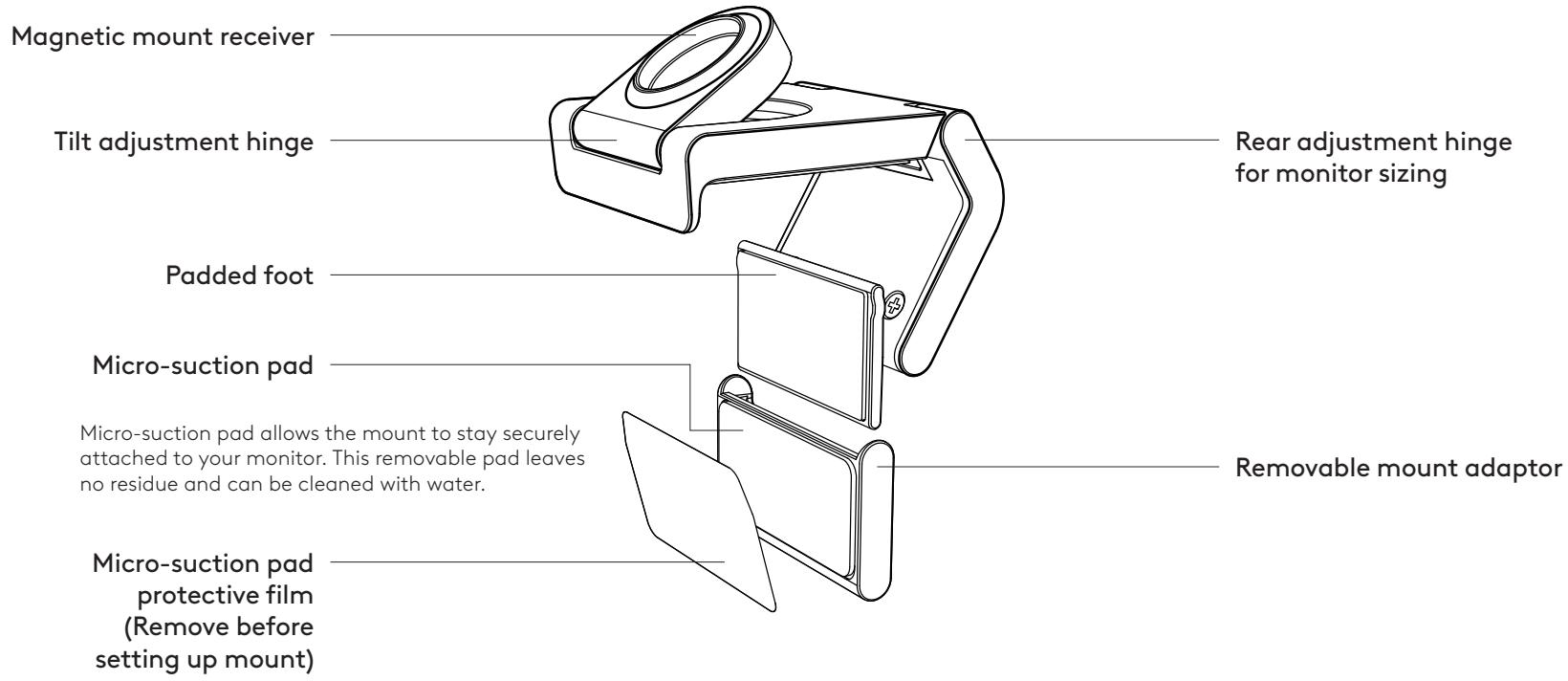
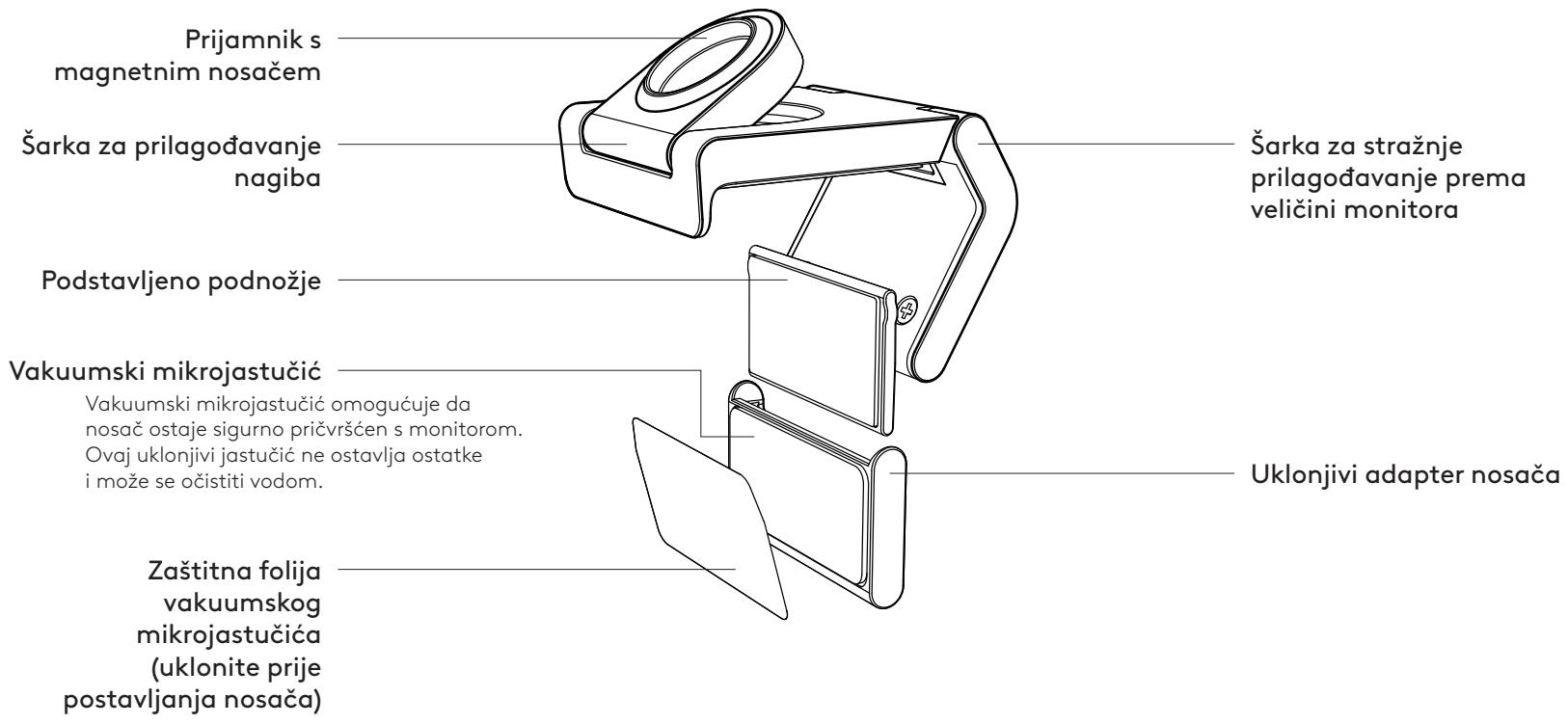
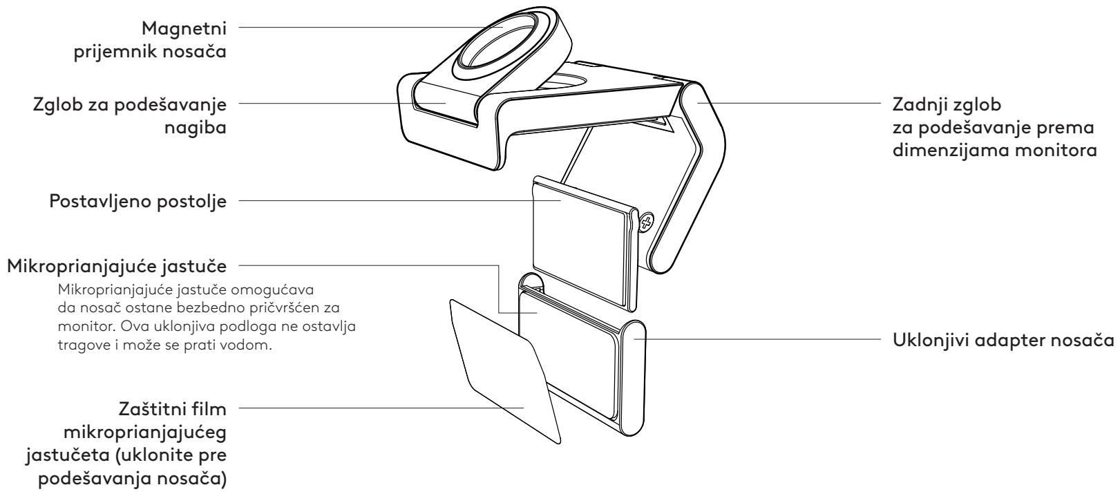
MOUNT DESIGN OVERVIEW
STEP 1: WHAT'S IN THE BOX
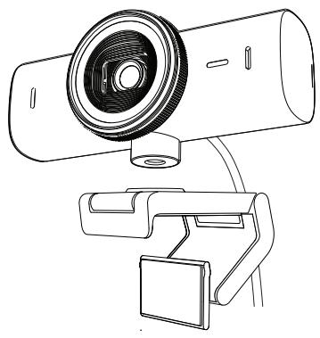
- Webcam MX Brio 705 for Business
- USB-C 3.0 cable
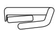
- Mount clip with removable mount adaptor
- User documentation
USB-C 3.0

STEP 2: DETERMINE MOUNT PLACEMENT
Placement to allow one-handed camera adjustments (using micro-suction pad)
- Determine the best placement for your webcam before continuing.
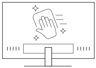
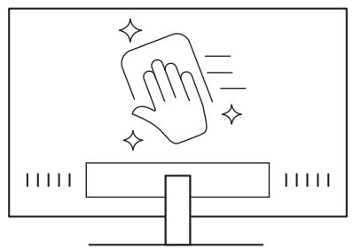
- Wipe the back of your monitor to clear any dust or dirt.
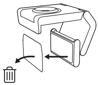
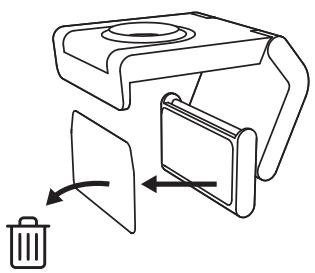
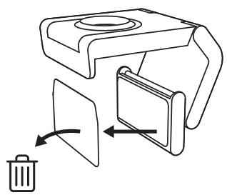
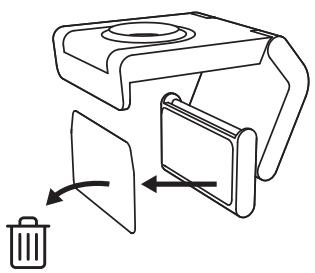
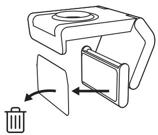
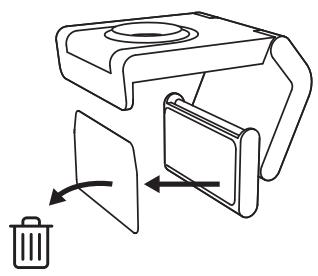
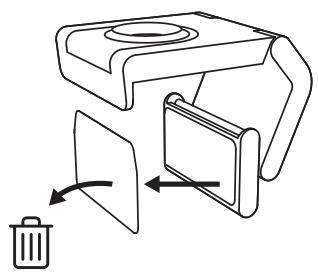
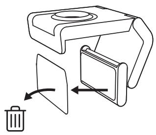
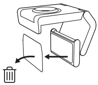
- Remove the protective film from the micro-suction pad.
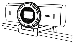
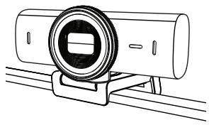
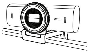
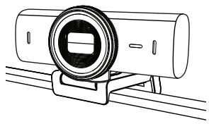
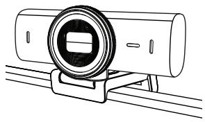
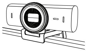
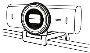
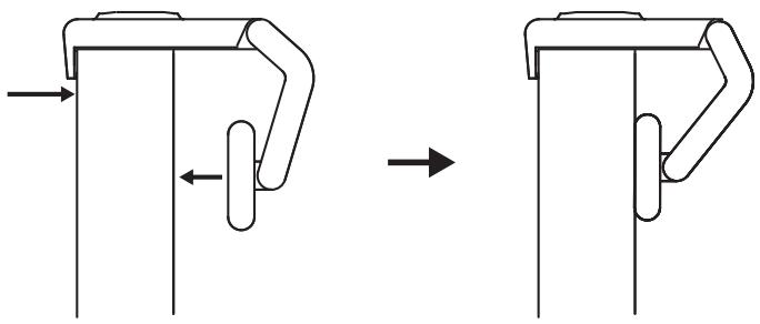
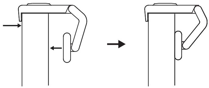
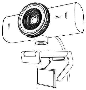
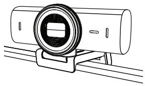
- Open the mount fully and place it on top of your monitor, ensuring that the pad of the front clip makes contact with the front of the monitor.
- Rotate the rear foot down until it makes contact with the back of the monitor.
- Press the micro-suction pad firmly against the back of your monitor to create a strong bond.
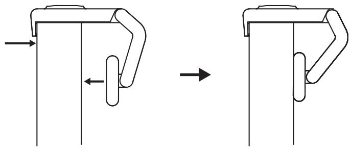
Note:
- The mount adapter can be removed and reused for mounting adjustments without leaving residue.
- To clean the micro-suction pad, rinse it with water to remove debris, and let it air dry to regain strong suction.
(Optional) Placement without the micro-suction pad
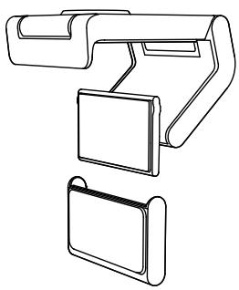
Slide the removable mount adapter down to remove it from the webcam foot. Adjust the foot on the mounting clip until it is flush with the back of your device and press firmly in place.
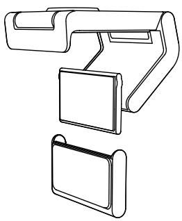
STEP 3: MOUNT ADAPTER REMOVAL AND CLEANING
- Remove the webcam from the mount and gently peel the adapter from one corner to remove it.
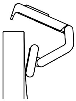
- With a wet finger, gently rub the pad to clear it of dust and dirt, and let the micro-suction pad air dry completely before remounting (do not use cloth or tissue to dry).
- Repeat the monitor placement setup steps to best deploy your webcam.
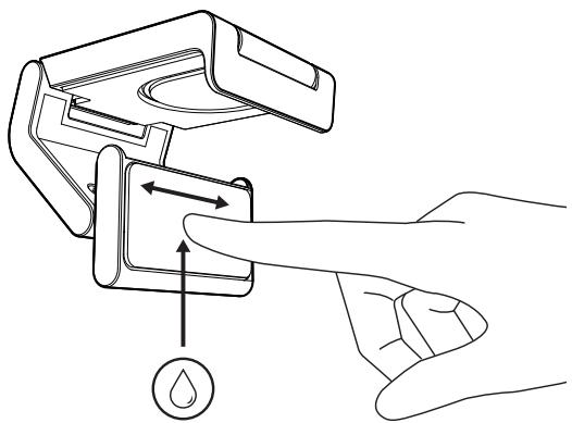
STEP 4: ATTACH CAMERA TO THE MOUNT
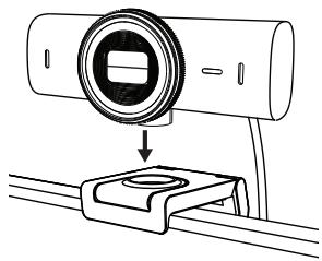
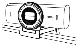
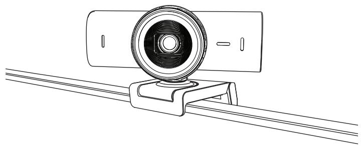
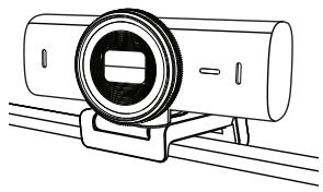
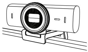
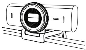
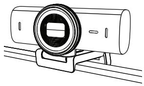
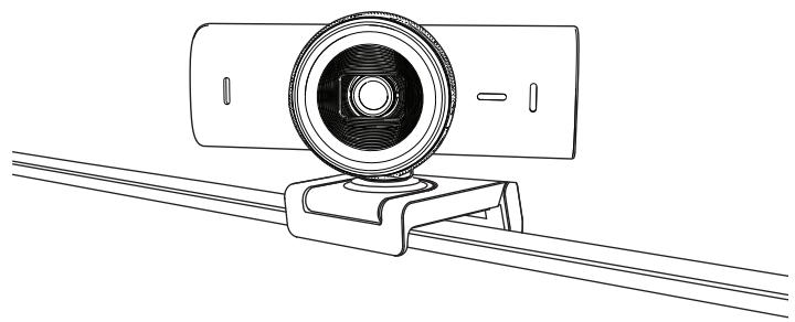
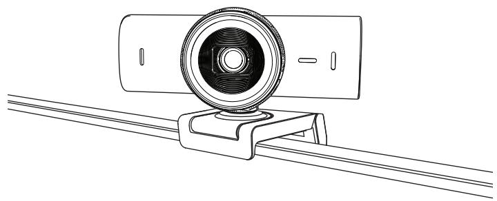
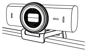
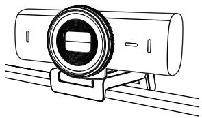
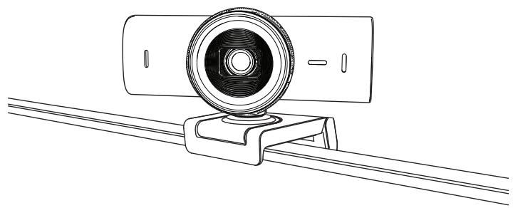
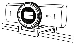
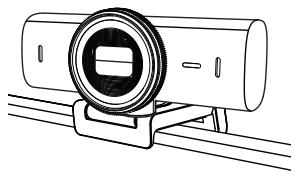
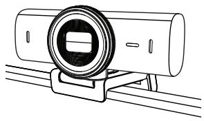
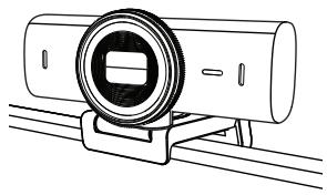
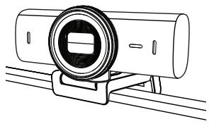
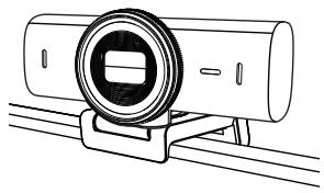
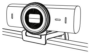
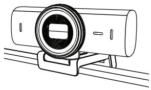
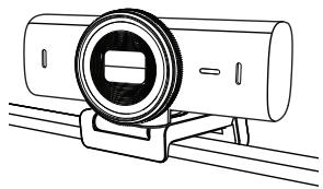
Place the webcam into the magnet attachment point on top of the mount. Listen for an audible click indicating the webcam is properly seated on the mount.
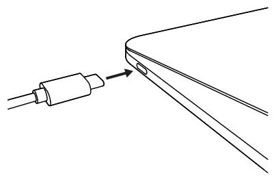
STEP 5: CONNECT THE WEBCAM VIA USB-C & GET STARTED
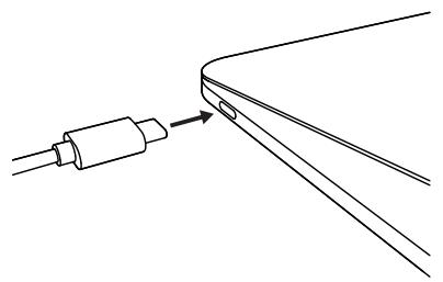
- Plug the USB-C connector into the USB-C port on your computer, monitor, laptop, or docking station.
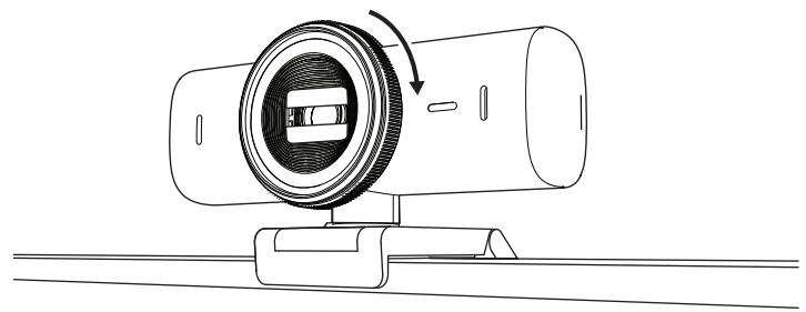
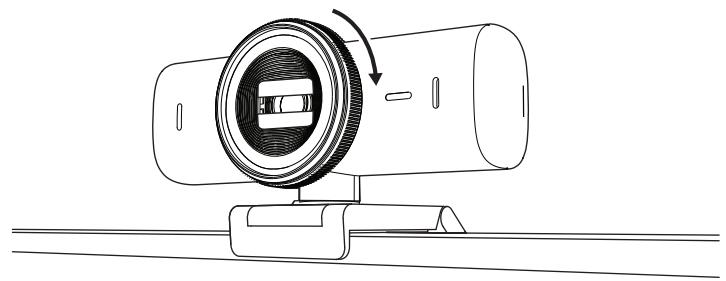
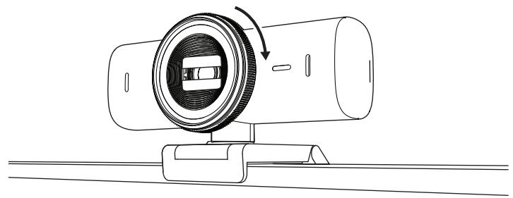
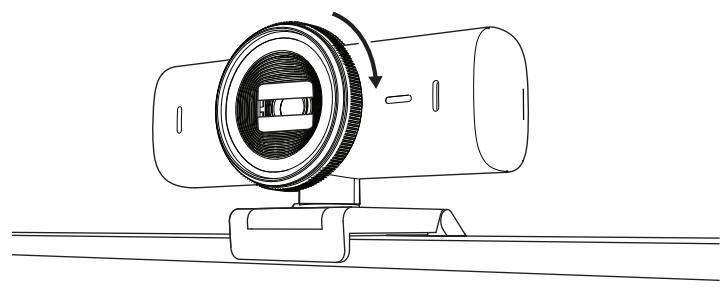
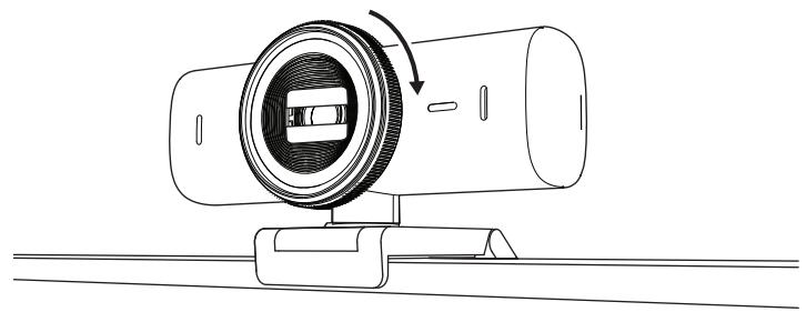
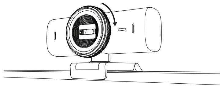
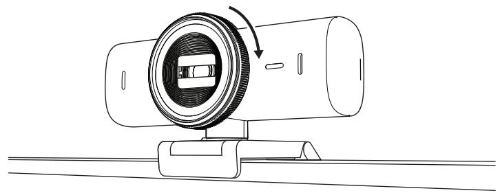
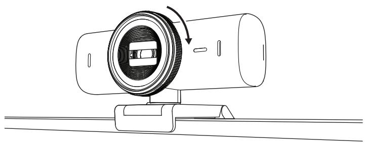
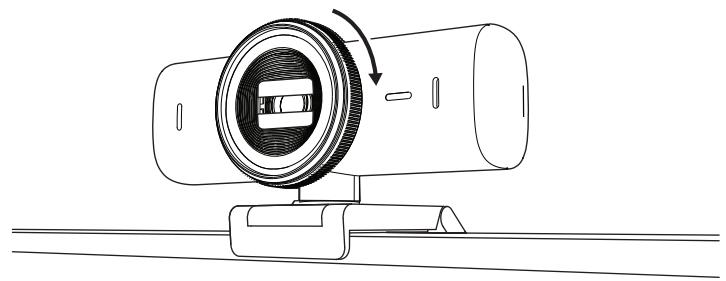
- Rotate the dial at the front of the webcam to open/close the privacy shutter.
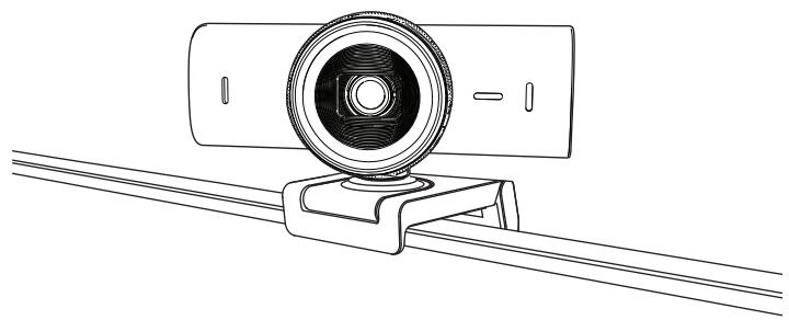
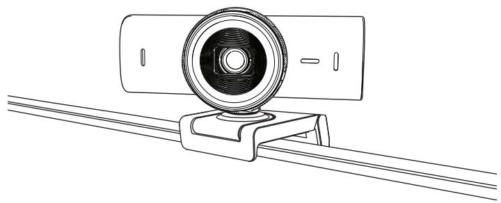
- Adjust the webcam by turning side to side and tilting up and down to find the best framing for your video meetings.
STEP 6: SUCCESSFUL CONNECTION
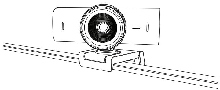
LED activity light will light up when the webcam is in use by any video application.
LED activity lights:
• Video ON / Audio ON: White • Video ON / Audio OFF: White - Video OFF / Audio ON: Yellow - Video OFF / Audio OFF: No light - Firmware Update: Breathing Lilac
STEP 7: SHOW MODE
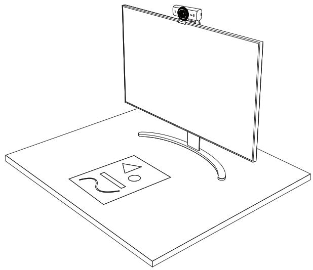
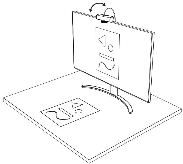
Easily show physical items in video calls by tilting the camera down to present sketches, objects, and work in progress. There are two ways to use Show Mode:
1. If mount is secured with micro-suction pad:
Using one hand, tilt the camera down to show your desktop, and tilt back up to show yourself.
2. If the mount is not secured with the micro-suction pad:
Hold the mount still with one hand and tilt the camera up or down with the other.
Note:
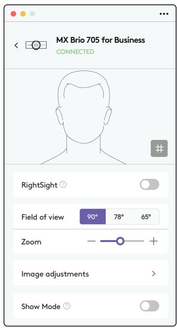
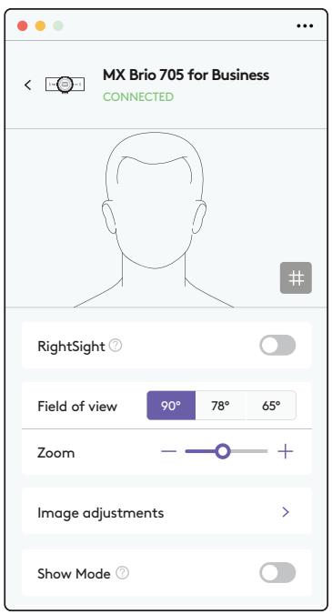
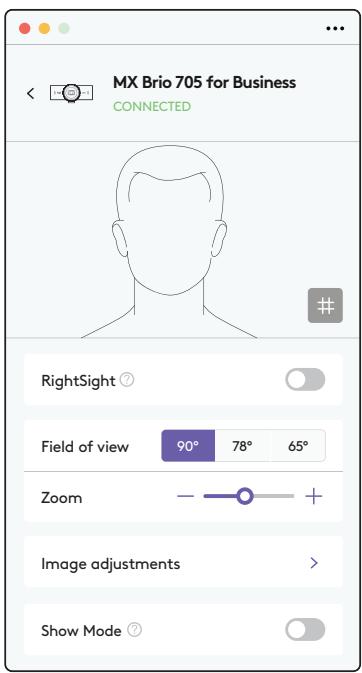
The Show Mode feature requires users to download and use Logi Tune.
STEP 8: LOGI TUNE
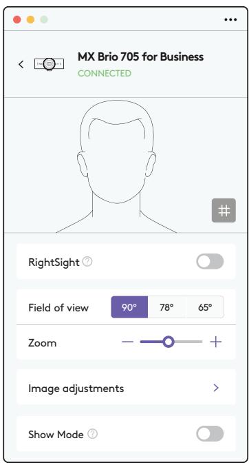
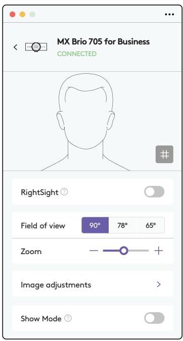
Logi Tune helps boost your webcam performance with periodic software and firmware updates.
It is recommended to update your webcam.
To do so, download Logi Tune from
www.logitech.com/tune

www.logitech.com/tune
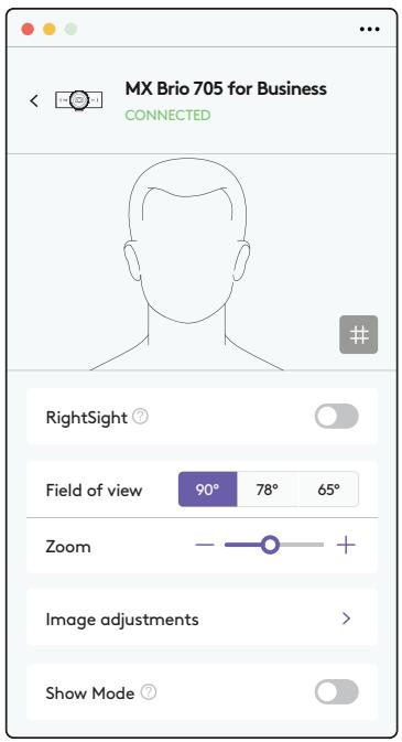
ADJUSTABLE OPTIONS
- Show Mode
- Auto-framing
- Zoom adjustment ● Field of View (90°/78°/65°)
- Image adjustment
- Auto-focus
- Disable mics
- LED on/off for video and audio
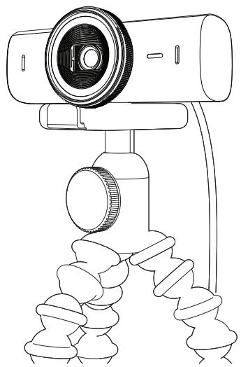
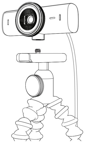
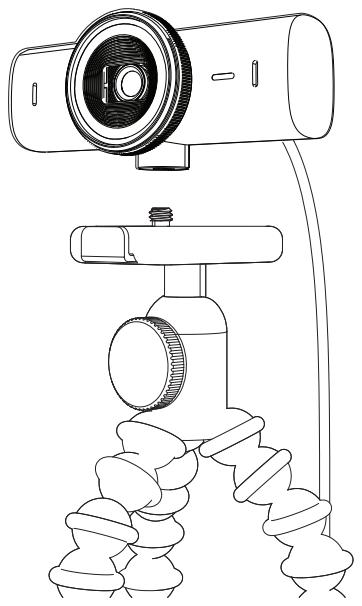
STEP 9: (OPTIONAL) ATTACH TO A TRIPOD
For placement on a tripod (not included)
- Remove the detachable universal mounting clip from the webcam.
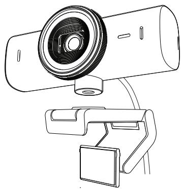
- Locate the 1/4 inch tripod thread on the bottom of the webcam.
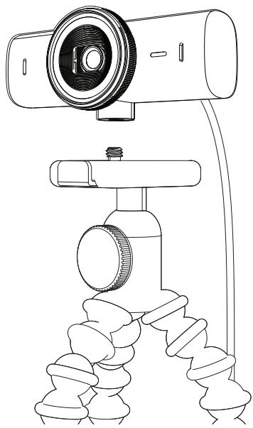
- Secure the webcam on your tripod by twisting it into the 1/4 inch thread.
- Repeat the monitor placement setup steps to best deploy your webcam.
- Please refer to step 5 and 6 to complete your webcam setup.
DIMENSIONS
WEBCAM:
Height x Width x Depth:
1.7 in (43.6 mm) x 3.9 in (98 mm) x 1.4 in (36.2 mm)
Height x Width x Depth:
2.4 in (61.6 mm) x 3.9 in (98 mm) x 2.1 in (52.2 mm), incl. mount clip
Weight: 4.8 oz (136 g)
Weight: 6.1 oz (174 g), incl. mount clip
Attached cable length: 5 ft (1.5 m)
MOUNTING CLIP:
Height x Width x Depth:
1 in (25 mm) x 1.8 in (45.8 mm) x 2.6 in (65.1 mm)
Weight: 1.4 oz (40 g), incl. removable mount adapter
www.logitech.com/prosupport/mx-brio-705-for-business
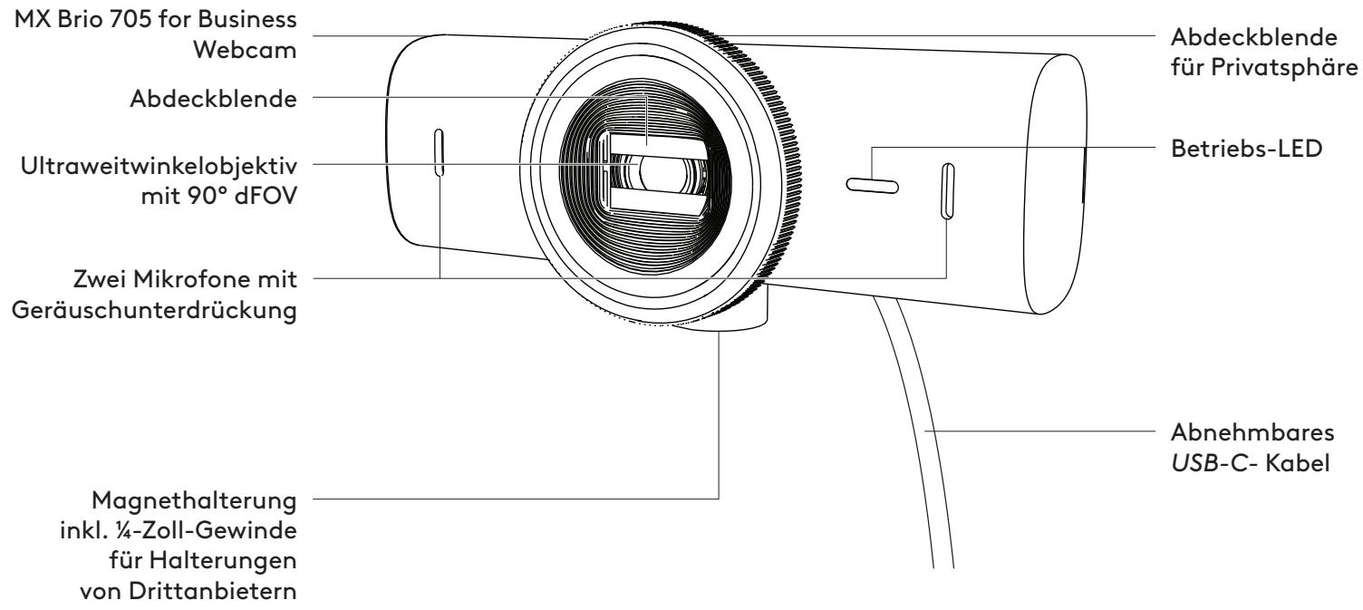
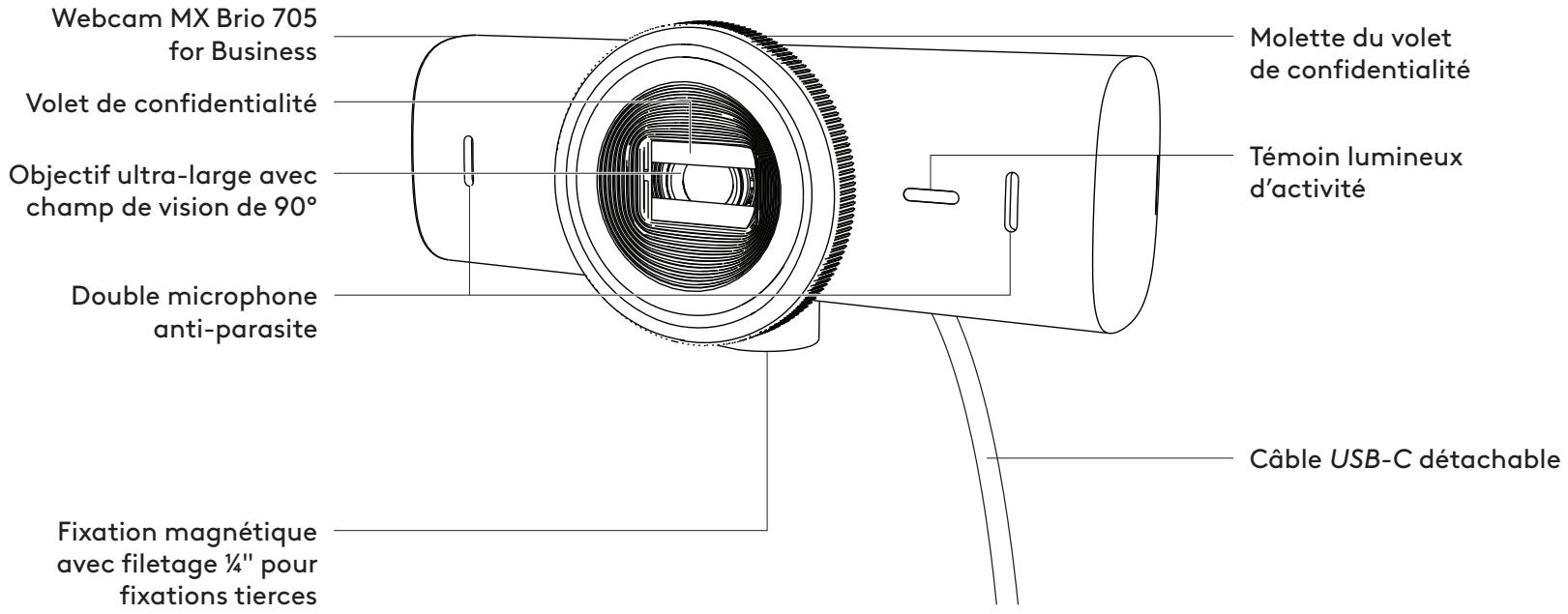
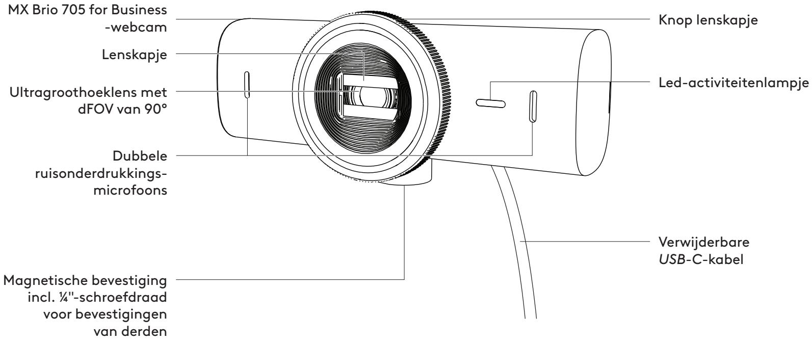
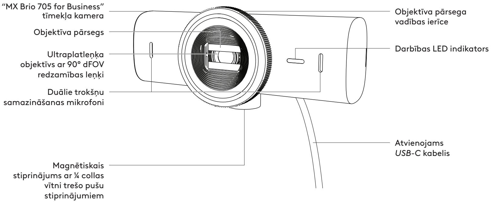
PRODUCT AT A GLANCE
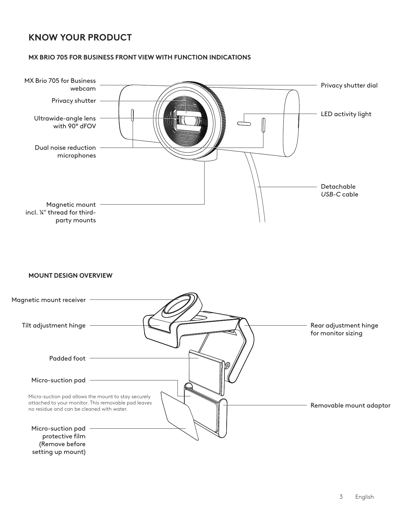
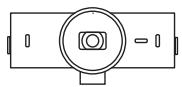
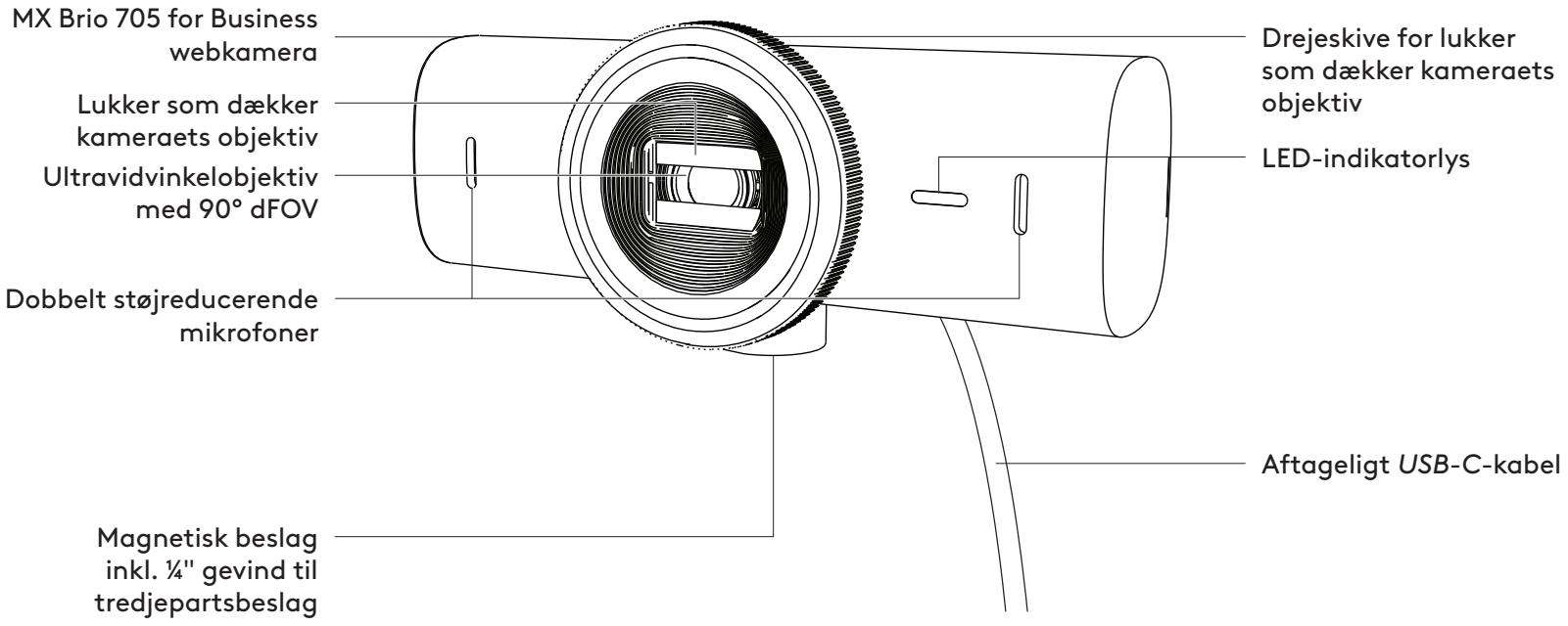
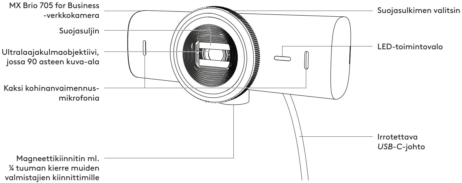
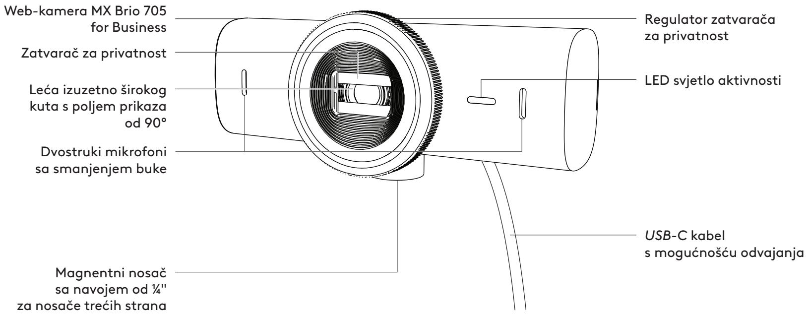
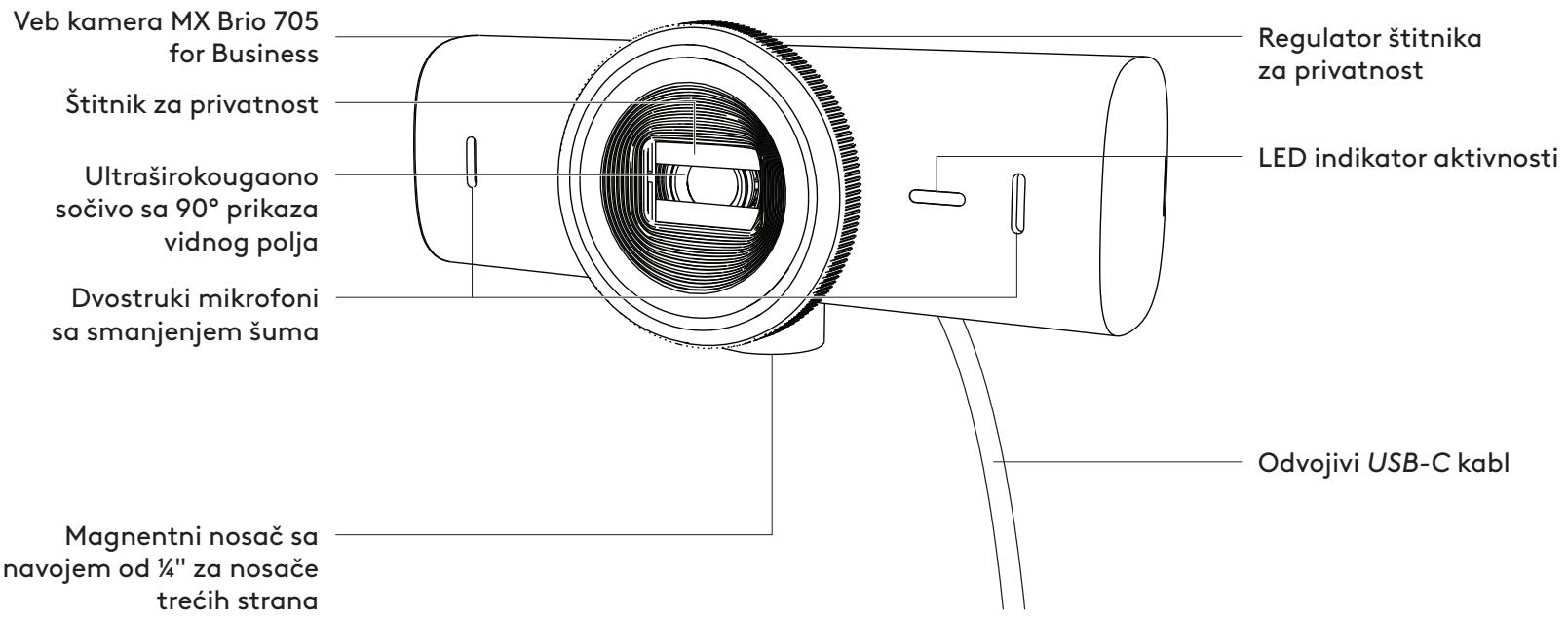
MX BRIO 705 FOR BUSINESS FRONT VIEW WITH FUNCTION INDICATORS
Note:
STEP 7: SHOW MODE
Note:
STEP 8: LOGI TUNE
www.logitech.com/tune

www.logitech.com/tune
CUSTOMIZABLE OPTIONS
STEP 9: (OPTIONAL) MOUNTING ON A TRIPOD
DIMENSIONS
WEBCAM:
www.logitech.com/prosupport/mx-brio-705-for-business
PRODUCT OVERVIEW
FRONT VIEW OF MX BRIO 705 FOR BUSINESS WITH FUNCTION INDICATORS
Note:
STEP 3: REMOVAL AND CLEANING OF THE MOUNTING ADAPTER
STEP 4: MOUNTING THE CAMERA
STEP 5: CONNECTING THE WEBCAM VIA USB-C AND GETTING STARTED
STEP 6: CONNECTION SUCCESSFUL
Note:
www.logitech.com/tune
ADJUSTABLE OPTIONS
STEP 9: (OPTIONAL) TRIPOD MOUNTING
DIMENSIONS
WEBCAM:
www.logitech.com/prosupport/mx-brio-705-for-business
PRODUCT OVERVIEW
Note:
STEP 4: ATTACH THE CAMERA TO THE MOUNT
STEP 5: CONNECT THE WEBCAM VIA USB-C AND START USING IT
STEP 6: CONNECTION SUCCESSFUL
STEP 7: SHOW MODE
Note:
www.logitech.com/tune
ADJUSTABLE OPTIONS
STEP 9: (OPTIONAL) ATTACH TO A TRIPOD
DIMENSIONS
WEBCAM:
www.logitech.com/prosupport/mx-brio-705-for-business
PRODUCT COMPONENTS
Note:
STEP 4: ATTACH THE CAMERA TO THE MOUNT
STEP 5: CONNECT THE WEBCAM VIA USB-C AND START
STEP 6: CONNECTION SUCCESSFUL
Note:
www.logitech.com/tune
ADJUSTABLE OPTIONS
STEP 9: (OPTIONAL) ATTACH TO A TRIPOD
DIMENSIONS
WEBCAM:
www.logitech.com/prosupport/mx-brio-705-for-business
Note:
STEP 4: ATTACH THE CAMERA TO THE MOUNT
STEP 5: CONNECT THE WEBCAM VIA USB-C AND START
Note:
www.logitech.com/tune
ADJUSTABLE OPTIONS
- Locate the 1/4-inch tripod thread on the bottom of the webcam.
DIMENSIONS
WEBCAM:
www.logitech.com/prosupport/mx-brio-705-for-business
FRONT VIEW MX BRIO 705 FOR BUSINESS WITH FUNCTION OVERVIEW
Note:
STEP 3: REMOVE AND CLEAN THE MOUNT ADAPTER
STEP 4: ATTACH THE CAMERA TO THE MOUNT
STEP 5: CONNECT THE WEBCAM VIA USB-C AND GET STARTED
STEP 6: SUCCESSFUL CONNECTION
Note:
www.logitech.com/tune

www.logitech.com/tune
CUSTOMIZABLE OPTIONS
STEP 9: (OPTIONAL) MOUNT ON A TRIPOD
DIMENSIONS
WEBCAM:
www.logitech.com/prosupport/mx-brio-705-for-business
PRODUCT OVERVIEW
FRONT VIEW OF MX BRIO 705 FOR BUSINESS WITH FUNCTION INDICATORS

Note!
STEP 3: REMOVAL AND CLEANING OF THE MOUNTING ADAPTER
STEP 6: CONNECTION
Note!
www.logitech.com/tune
ADJUSTABLE OPTIONS
STEP 9: (OPTIONAL) MOUNT ON A TRIPOD
DIMENSIONS
WEBCAM:
www.logitech.com/prosupport/mx-brio-705-for-business
PRODUCT OVERVIEW
MX BRIO 705 FOR BUSINESS SET FRONT VIEW WITH FUNCTION INDICATORS
Note:
STEP 3: MOUNTING THE ADAPTER AND CLEANING
STEP 4: ATTACH THE CAMERA TO THE MOUNT
STEP 5: CONNECT THE WEBCAM VIA USB-C AND GET STARTED
STEP 6: CONNECTION
Note!
www.logitech.com/tune
ADJUSTABLE OPTIONS
- Show Mode
- Auto-framing
- Zoom adjustment
- Field of view (90°/78°/65°)
- Image adjustment
- Autofocus
- Disable microphones
- LED on/off for video and audio
STEP 9: (OPTIONAL) MOUNT ON A TRIPOD
DIMENSIONS
WEBCAM:
www.logitech.com/prosupport/mx-brio-705-for-business
GET TO KNOW THE PRODUCT
MX BRIO 705 FOR BUSINESS SETUP WITH FUNCTION INDICATORS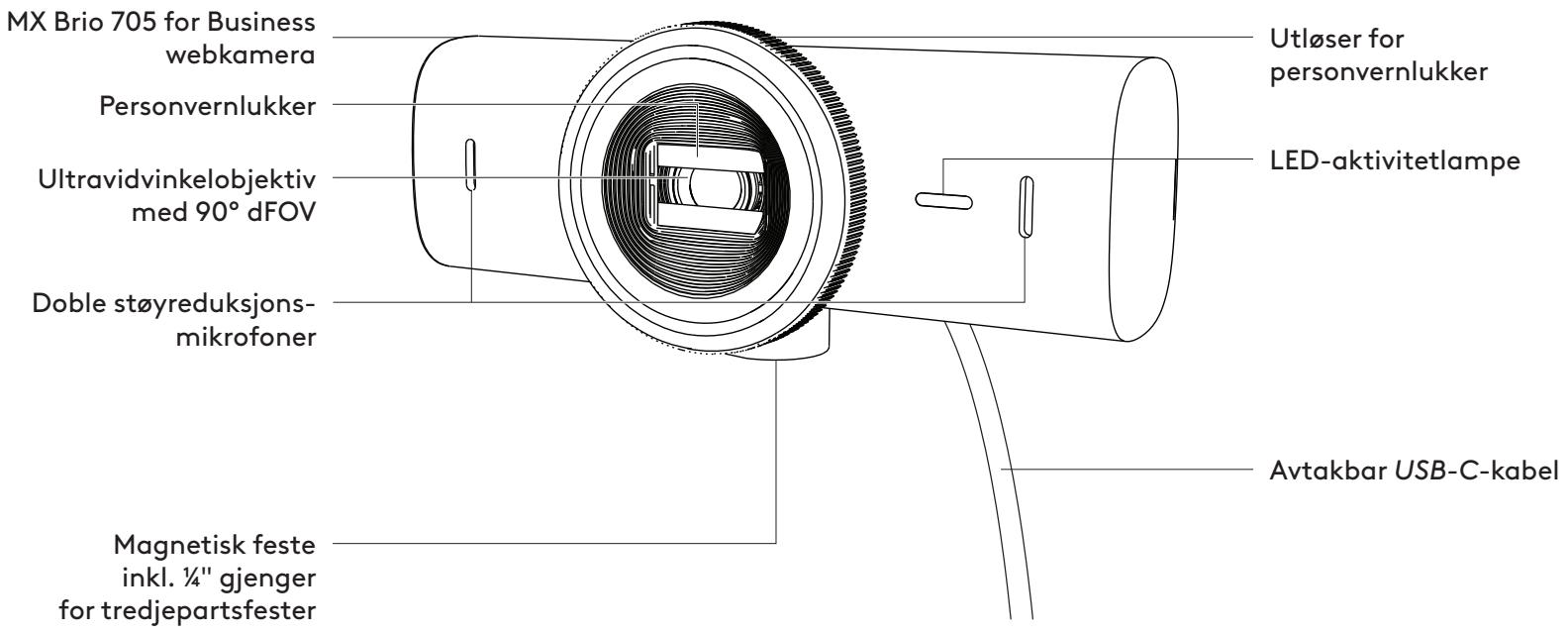
MOUNTING SETUP OVERVIEW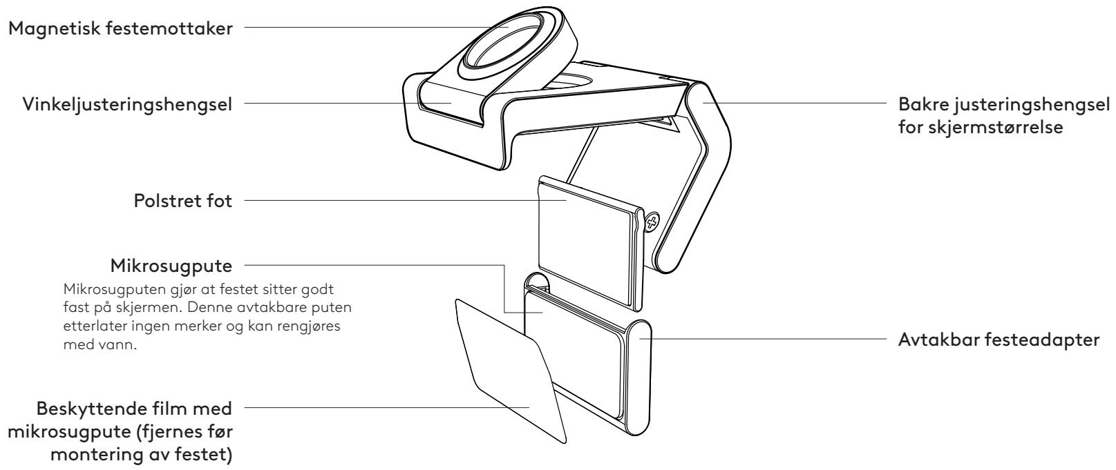
Note:
STEP 3: REMOVING AND CLEANING THE MOUNTING ADAPTER
STEP 5: CONNECTING THE WEBCAM VIA USB-C AND GETTING STARTED
STEP 6: CONNECTION COMPLETE
Note:
www.logitech.com/tune

www.logitech.com/tune
ADJUSTABLE OPTIONS
- Show Mode
- Automatic framing
- Zoom adjustment
- Field of view (90°/78°/65°)
- Image adjustment
- Autofocus
- Disable microphones
- LED on/off for video and audio
STEP 9: (OPTIONAL) ATTACH TO A TRIPOD
DIMENSIONS
WEBCAM:
www.logitech.com/prosupport/mx-brio-705-for-business
REGISTER YOUR PRODUCT
MX BRIO 705 FOR BUSINESS FRONT VIEW AND FEATURES
Note:
STEP 3: REMOVING AND CLEANING THE MOUNTING ADAPTER
STEP 5: CONNECT THE WEBCAM VIA THE USB-C PORT AND START
STEP 6: CONNECTION ESTABLISHED
Note:
www.logitech.com/tune
ADJUSTABLE OPTIONS
STEP 9: (OPTIONAL) ATTACH TO TRIPOD
DIMENSIONS
WEBCAM:
www.logitech.com/prosupport/mx-brio-705-for-business
Note:
Note:
www.logitech.com/tune
ADJUSTMENT OPTIONS
STEP 9: (OPTIONAL) ATTACH TO TRIPOD
DIMENSIONS
WEBCAM:
www.logitech.com/prosupport/mx-brio-705-for-business
Note.
Note:
www.logitech.com/tune
CUSTOMIZABLE SETTINGS
DIMENSIONS
WEBCAM
www.logitech.com/prosupport/mx-brio-705-for-business
DEVICE DESCRIPTION
MX BRIO 705 FOR BUSINESS – FRONT VIEW WITH FUNCTION LABELS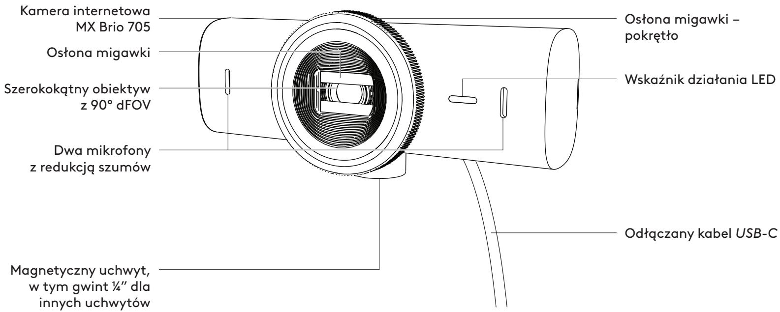
Note:
STEP 3: DISASSEMBLY AND CLEANING OF THE MOUNTING ADAPTER
STEP 4: MOUNTING THE CAMERA TO THE BRACKET
STEP 5: CONNECT THE WEBCAM VIA USB-C AND START WORKING
STEP 6: SUCCESSFUL CONNECTION
Note:
www.logitech.com/tune
ADJUSTMENT OPTIONS
STEP 9 (OPTIONAL) MOUNTING ON A TRIPOD
DIMENSIONS
WEB CAMERA:
www.logitech.com/prosupport/mx-brio-705-for-business
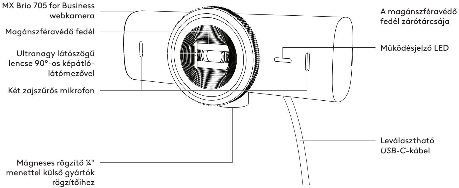
PRODUCT OVERVIEW
MX BRIO 705 FOR BUSINESS FRONT VIEW WITH FUNCTION INDICATORS
Note:
STEP 5: CONNECT THE WEBCAM WITH THE USB-C CONNECTOR AND GET TO WORK
STEP 6: SUCCESSFUL CONNECTION
Note:
www.logitech.com/tune
STEP 9: (OPTIONAL) MOUNTING ON A TRIPOD
DIMENSIONS
WEBCAM:
www.logitech.com/prosupport/mx-brio-705-for-business
PRODUCT DESCRIPTION
MX BRIO 705 FOR BUSINESS - FRONT VIEW WITH FUNCTION DESCRIPTION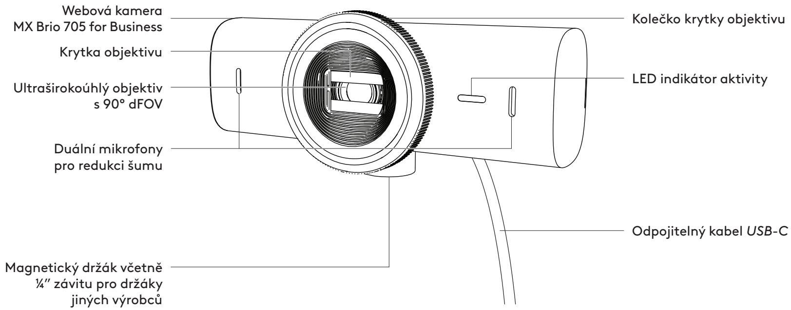
Note:
STEP 3: DISASSEMBLY AND CLEANING OF THE MOUNTING ADAPTER
STEP 4: ATTACH THE CAMERA TO THE MOUNT
STEP 5: CONNECTING THE WEBCAM VIA USB-C AND STARTING UP
STEP 6: SUCCESSFUL CONNECTION
Note:
www.logitech.com/tune
ADJUSTABLE OPTIONS
STEP 9: (OPTIONAL) ATTACHING TO A TRIPOD
DIMENSIONS
WEBCAM:
www.logitech.com/prosupport/mx-brio-705-for-business
PRODUCT DESCRIPTION
MX BRIO 705 FOR BUSINESS - FRONT VIEW WITH FUNCTION DESCRIPTIONS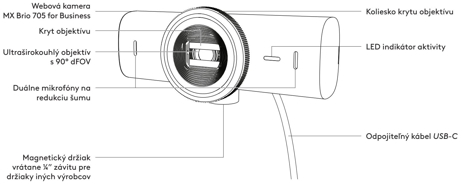
Note:
STEP 3: DISASSEMBLY AND CLEANING OF THE MOUNTING ADAPTER
STEP 4: ATTACH THE CAMERA TO THE MOUNT
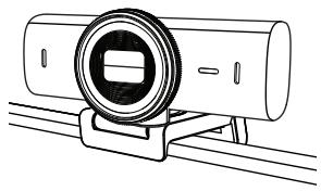
STEP 5: CONNECTING THE WEBCAM VIA USB-C AND STARTING OPERATION
- Connect the USB-C connector to the USB-C port on your computer, monitor, laptop, or docking station.
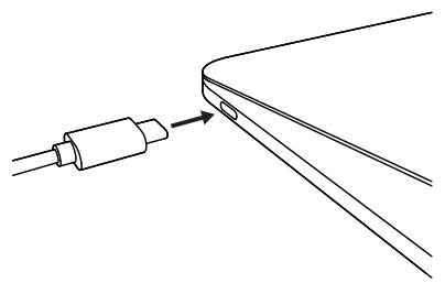
STEP 6: SUCCESSFUL CONNECTION
Note:
www.logitech.com/tune
ADJUSTABLE OPTIONS
STEP 9: (OPTIONAL) MOUNTING ON A TRIPOD
DIMENSIONS
WEBCAM:
www.logitech.com/prosupport/mx-brio-705-for-business
Note.
Note.
www.logitech.com/tune
DIMENSIONS
WEBCAM:
www.logitech.com/prosupport/mx-brio-705-for-business
PRODUCT OVERVIEW
MX BRIO 705 FOR BUSINESS FRONT VIEW WITH FUNCTION REFERENCES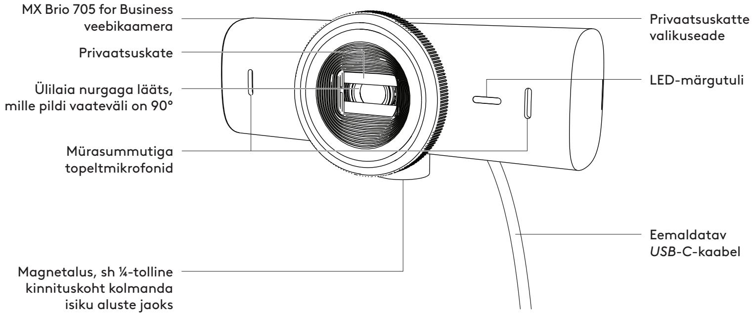
Note.
STEP 3. REMOVING AND CLEANING THE MOUNTING ADAPTER
STEP 5. CONNECT THE WEBCAM VIA USB-C AND START USING IT
STEP 6. SUCCESSFUL CONNECTION
Note.
www.logitech.com/tune
OPTIONAL SETTINGS
9. STEPS. (OPTIONAL) MOUNTING TO THE STAND
DIMENSIONS
WEBCAM:
www.logitech.com/prosupport/mx-brio-705-for-business
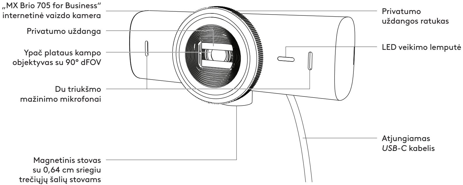
CONTENTS
"MX BRIO 705 FOR BUSINESS" FRONT VIEW WITH FUNCTION INDICATORS
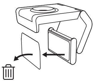
- Remove the protective film from the micro-suction pad.
Note.
3. OPERATION. REMOVING AND CLEANING THE MOUNTING ADAPTER
4. OPERATION. ATTACHING THE CAMERA TO THE MOUNT
5. OPERATION. CONNECTING THE CAMERA WITH USB-C AND STARTING WORK
6. OPERATION. ESTABLISHING A SUCCESSFUL CONNECTION
Note.
www.logitech.com/tune
CUSTOMIZATION OPTIONS
9. OPERATION. (OPTIONAL) MOUNTING TO A STAND
DIMENSIONS
WEBCAM
www.logitech.com/prosupport/mx-brio-705-for-business
GET TO KNOW YOUR PRODUCT
MX BRIO 705 FOR BUSINESS FRONT VIEW WITH INDICATED FUNCTIONS
Note.
STEP 3. REMOVING AND CLEANING THE TRIPOD ADAPTER
STEP 4. MOUNTING THE CAMERA TO THE TRIPOD
STEP 5. CONNECT THE WEBCAM VIA USB-C AND START
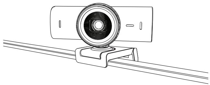
STEP 6. SUCCESSFUL CONNECTION
2. If the mount is not attached with the micro-suction cup:
Note.
www.logitech.com/tune
ADJUSTABLE OPTIONS
STEP 9. (OPTIONAL) ATTACH TO TRIPOD
DIMENSIONS
www.logitech.com/prosupport/mx-brio-705-for-business
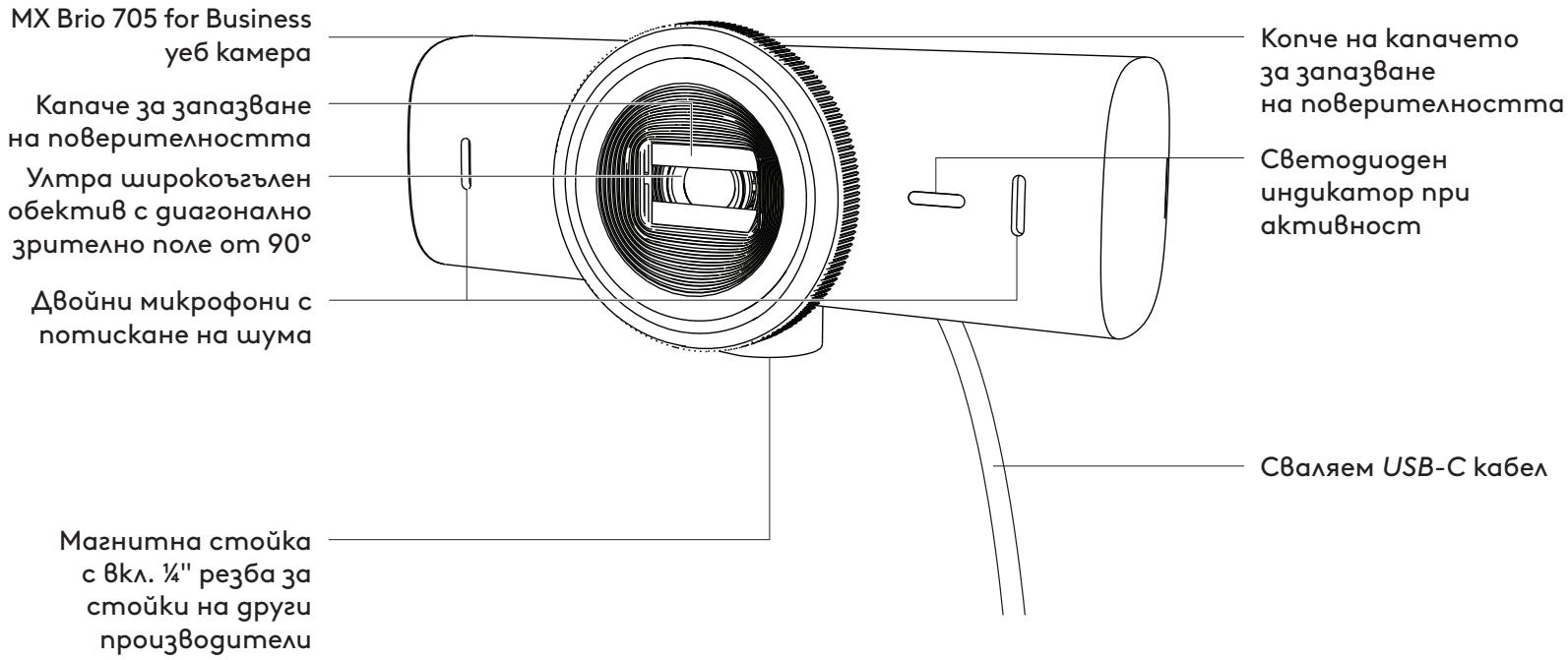
GET TO KNOW YOUR PRODUCT
FRONT VIEW OF MX BRIO 705 FOR BUSINESS WITH FUNCTION INDICATORS
Note:
Note:
www.logitech.com/tune
ADJUSTABLE OPTIONS
DIMENSIONS
WEB CAMERA:
www.logitech.com/prosupport/mx-brio-705-for-business
GET TO KNOW YOUR DEVICE
FRONT VIEW OF THE MX BRIO 705 FOR BUSINESS DEVICE WITH FUNCTION INDICATORS
MOUNT DESIGN OVERVIEW
1. STEP: BOX CONTENTS
- MX Brio 705 for Business webcam
- USB-C 3.0 cable
- Mount holder with removable mount adapter
- User documentation
USB-C 3.0

2. STEP: DETERMINE MOUNT POSITION
- Open the mount fully and place it on top of the monitor, ensuring that the front holder pad touches the front of the monitor.
- Rotate the rear base downward until it touches the back of the monitor.
- Press the vacuum micro-pad firmly against the back of the monitor to create a good grip.
Note:
- The mount adapter can be removed and reused for mounting adjustments without leaving marks.
- To clean the vacuum micro-pad, rinse it with water and remove dirt, then let it dry to reactivate the vacuum.
(Optional) Setup without the vacuum micro-pad
3. STEP: REMOVING AND CLEANING THE MOUNT ADAPTER
STEP 4: ATTACHING THE CAMERA TO THE MOUNT
STEP 5: CONNECTING THE WEBCAM VIA USB-C CABLE AND STARTING
- Rotate the dial on the front of the webcam to open/close the privacy shutter.
- Adjust the webcam by rotating it from side to side and tilting it up and down to find the best framing for video conferences.
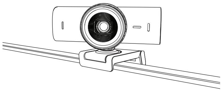
STEP 6: SUCCESSFUL CONNECTION
Note:
The Show Mode feature requires the user to download and use Logi Tune.
STEP 8: LOGI TUNE
Logi Tune enhances webcam performance with regular software and firmware updates.
It is recommended to update the webcam. If you wish to do so, download Logi Tune at www.logitech.com/tune

www.logitech.com/tune
ADJUSTABLE FEATURES
STEP 9: (OPTIONAL) MOUNTING ON A TRIPOD
For mounting on a tripod (not included)
- Remove the detachable universal mounting clip from the webcam.
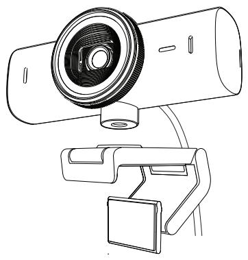
- Find the 1/4-inch thread on the tripod at the bottom of the webcam.
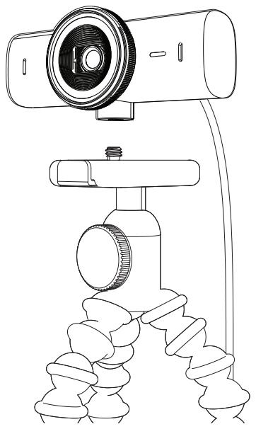
- Attach the webcam to the tripod by screwing it into the 1/4-inch thread.
- Repeat the monitor setup steps to mount the webcam in the best possible way.
- See steps 5 and 6 to complete the webcam setup.
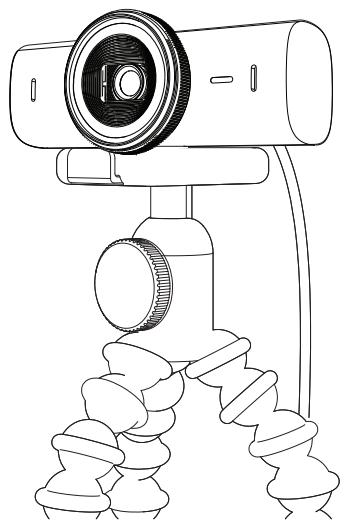
DIMENSIONS
WEBCAM:
www.logitech.com/prosupport/mx-brio-705-for-business
GET TO KNOW YOUR PRODUCT
FRONT VIEW OF MX BRIO 705 FOR BUSINESS DEVICE WITH FUNCTION LABELS
MOUNT OVERVIEW
STEP 1: PACKAGE CONTENTS
- MX Brio 705 for Business webcam
- USB-C 3.0 cable
- Mounting clip with removable bracket adapter
- User documentation


STEP 2: DETERMINING THE BRACKET POSITION
It is positioned to allow one-handed camera adjustments (using the micro-suction pad)
- Determine the best webcam position before continuing.
- Wipe the back of the monitor to remove dust or dirt.
- Remove the protective film from the micro-suction pad.
- Open the bracket fully and place it on the top of the monitor, so that the front clip pad comes into contact with the front of the monitor.
- Rotate the rear stand downward until it contacts the back of the monitor.
- Press the micro-suction pad firmly against the back of the monitor to ensure a good connection.
Note:
- The bracket adapter can be removed and reused for adjustments during installation without leaving marks.
- To clean the micro-suction pad, rinse it with water to remove dirt and let it air dry to restore its adhesive strength.
(Optional) Installation without the micro-suction pad
Pull the removable mount adapter downward to detach it from the webcam base. Adjust the mount on the mounting clip so that it is flush with the back of the device and press firmly.
STEP 3: REMOVING AND CLEANING THE MOUNT ADAPTER
- Remove the webcam from the mount and gently pull the adapter from one corner to remove it.
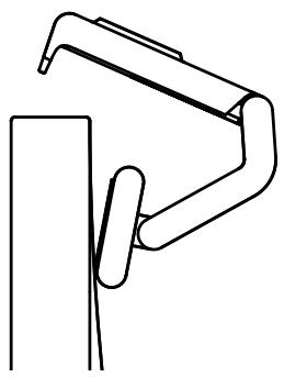
- With a damp finger, gently clean the micro-suction pad from dust and dirt, then let it air dry completely before reattaching (do not dry it with a cloth or tissue).
- Repeat the steps for adjusting the monitor position to best position the webcam.
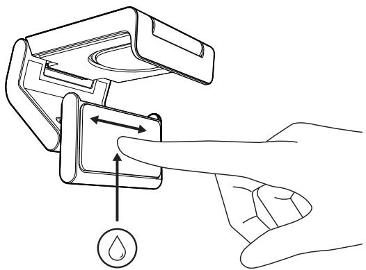
STEP 4: ATTACHING THE CAMERA TO THE MOUNT
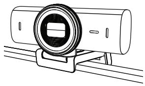
STEP 5: CONNECTING THE WEBCAM VIA USB-C AND GETTING STARTED
- Insert the USB-C connector into the USB-C port on your computer, monitor, laptop, or docking station.
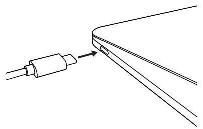
- Rotate the dial on the front of the webcam to open/close the privacy shutter.
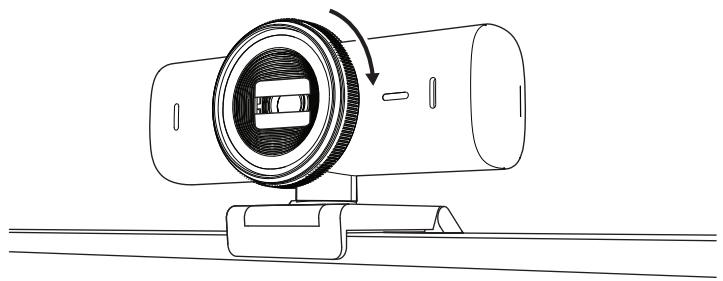
- Adjust the webcam by rotating the sides, or by tilting it down or up, to find the best framing for your video meetings.
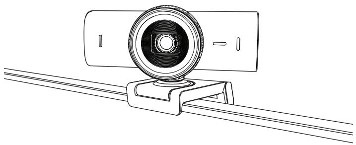
STEP 6: SUCCESSFUL CONNECTION
- If the mount is not attached with the micro-suction pad: Hold the mount steady with one hand and rotate the camera up or down with the other.
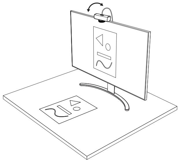
Note:
Show Mode feature requires the user to download and use Logi Tune.
STEP 8: LOGI TUNE
Logi Tune improves webcam performance with periodic software and firmware updates.
www.logitech.com/tune
ADJUSTABLE OPTIONS
- Show Mode
- Auto-framing
- Zoom adjustment
- Field of view (90°/78°/65°)
- Image adjustment
- Auto-focus
- Microphone mute
- Turning on/off LED indicator for video and audio
STEP 9: (OPTIONAL) MOUNTING ON A TRIPOD
For mounting on a tripod (not included)
- Remove the detachable universal mounting clip from the webcam.
- Locate the 1/4-inch tripod thread on the bottom of the webcam.
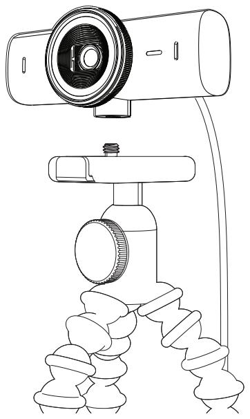
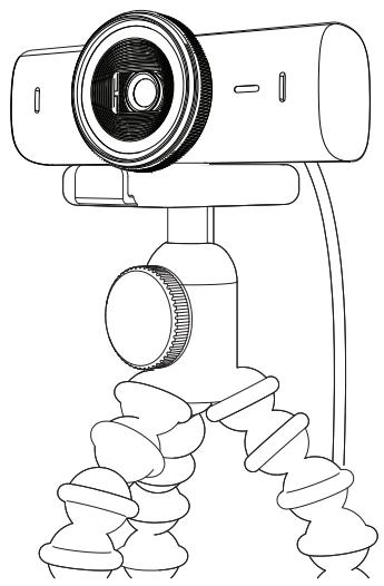
- Attach the webcam to a tripod by screwing the tripod onto the 6.35 mm (1/4-inch) thread.
- Repeat the steps for adjusting the monitor position to best position the webcam.
- See steps 5 and 6 to complete the webcam adjustment.
DIMENSIONS
WEBCAM:
www.logitech.com/prosupport/mx-brio-705-for-business
KNOW THE PRODUCT
MX BRIO 705 FOR BUSINESS – FRONT VIEW WITH FUNCTION INDICATORS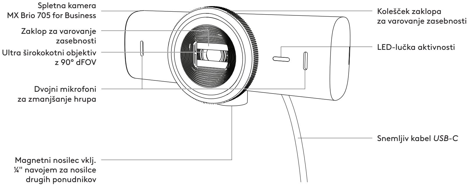
Note:
- The mount adapter can be removed and reused to adjust the installation without leaving any residue.
- To clean the micro suction pad, rinse it with water to remove dirt, and let it air dry to regain its strong suction function.
(Optional) Setup without the micro suction pad
STEP 3: REMOVING AND CLEANING THE MOUNT ADAPTER
STEP 4: ATTACHING THE CAMERA TO THE MOUNT

STEP 5: ESTABLISHING THE WEBCAM CONNECTION VIA USB-C AND STARTING
- Insert the USB-C connector into the USB-C port on your computer, monitor, laptop, or docking station.
STEP 6: SUCCESSFUL CONNECTION
2. If the mount is not attached with the micro suction pad:
Note:
www.logitech.com/tune
ADJUSTABLE OPTIONS
STEP 9: ATTACHING TO THE STAND (OPTIONAL)
DIMENSIONS
WEBCAM:
Height × width × depth:
43.6 mm (1.7 inches) x 98 mm (3.9 inches) x 36.2 mm (1.4 inches)
Height × width × depth:
www.logitech.com/prosupport/mx-brio-705-for-business
GET FAMILIAR WITH THE PRODUCT
FRONT VIEW OF THE MX BRIO 705 FOR BUSINESS WEB CAMERA, WITH FUNCTION INDICATORS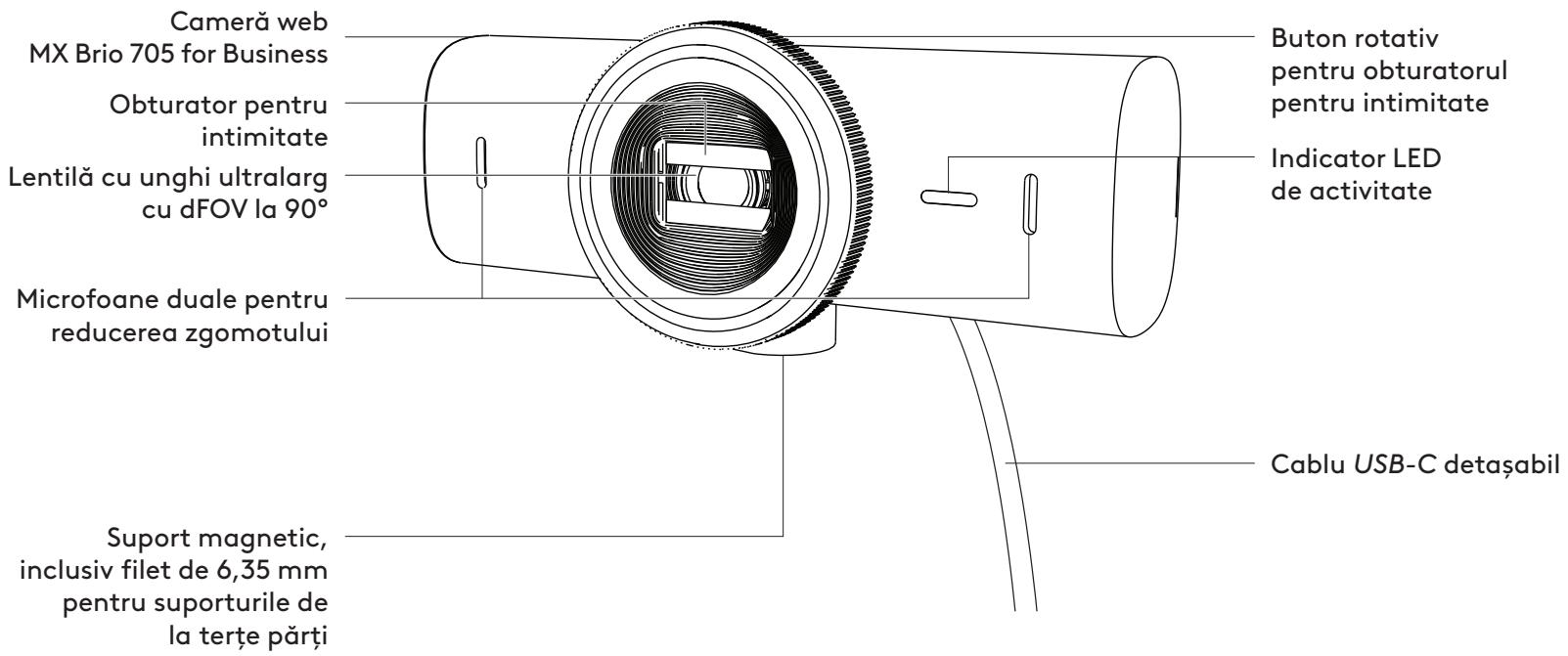
Note:
STEP 3: REMOVING AND CLEANING THE MOUNTING ADAPTER
STEP 4: ATTACHING THE CAMERA TO THE SUPPORT
STEP 5: CONNECTING THE WEB CAMERA VIA USB-C AND STARTING USE
STEP 6: SUCCESSFUL CONNECTION
Note:
www.logitech.com/tune
ADJUSTABLE OPTIONS
STEP 9: (OPTIONAL) ATTACHING TO A TRIPOD
DIMENSIONS
WEB CAMERA:
www.logitech.com/prosupport/mx-brio-705-for-business
GET TO KNOW YOUR PRODUCT
FRONT VIEW OF MX BRIO 705 FOR BUSINESS WITH FUNCTION INDICATORS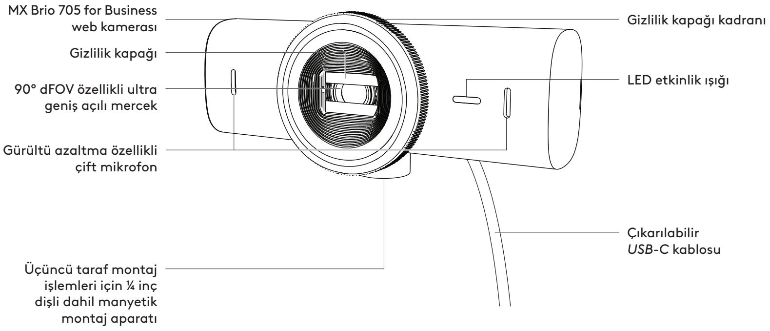
Note:
STEP 3: REMOVING AND CLEANING THE MOUNTING ADAPTER
STEP 4: ATTACHING THE CAMERA TO THE MOUNTING ADAPTER
STEP 5: CONNECTING AND STARTING THE WEB CAMERA WITH USB-C
STEP 6: SUCCESSFUL CONNECTION
www.logitech.com/tune
STEP 9: (OPTIONAL) MOUNTING ON A TRIPOD
DIMENSIONS
WEB CAMERA:
www.logitech.com/prosupport/mx-brio-705-for-business
Note:
Note:
www.logitech.com/tune
Web camera:
www.logitech.com/prosupport/mx-brio-705-for-business
Field of view: 4
www.logitech.com/tune
Show Mode •
•
• Get it
Angles (65°/78°/90°)
•
•
•
•
43.6 in x 98 in x 36.2 in
www.logitech.com/prosupport/mx-brio-705-for-business
Know your product
MX BRIO 705 FOR BUSINESS front view with feature indicators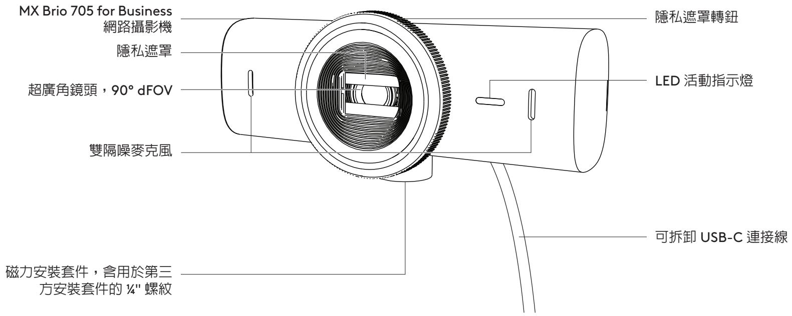
- Remove the protective film from the magnetic mount.
Note:
Step 3: Removing and cleaning the base adapter
Step 4: Attaching the webcam to the base
Step 6: Successful connection
Note:
www.logitech.com/tune

www.logitech.com/tune
Adjustable options
Step 9: (Optional) Attach to a tripod
To place on a tripod (not included)
- Remove the detachable universal mounting clip from the webcam.
Dimensions
Webcam:
Height x Width x Depth:
www.logitech.com/prosupport/mx-brio-705-for-business
Product description
Step 4: Attach the camera to the mount
Step 6: Connection successful
Note:
www.logitech.com/tune
Adjustable options
Specifications
Webcam:
Height x Width x Depth:
www.logitech.com/prosupport/mx-brio-705-for-business
PRODUCT OVERVIEW
MX BRIO 705 FOR BUSINESS FRONT VIEW WITH FUNCTION INDICATORS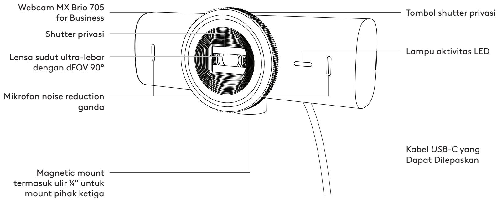
MOUNT DESIGN OVERVIEW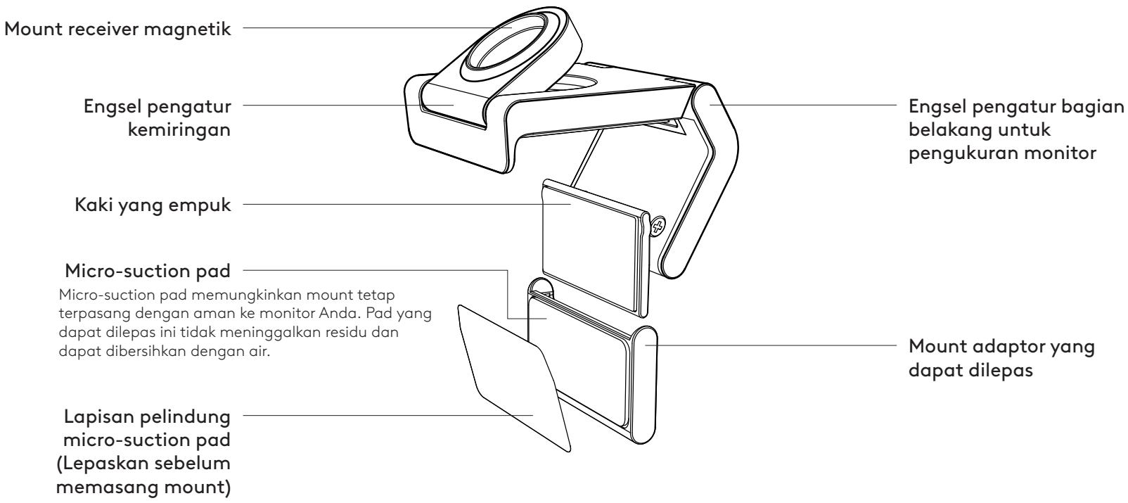
Note:
STEP 3: REMOVING AND CLEANING THE MOUNT ADAPTER
STEP 4: ATTACH THE CAMERA TO THE MOUNT
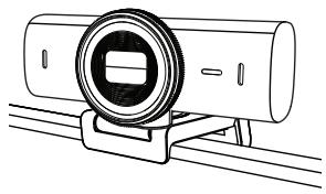
STEP 5: CONNECT THE WEBCAM VIA USB-C & START
- Plug the USB-C connector into the USB-C port on your computer, monitor, laptop, or docking station.
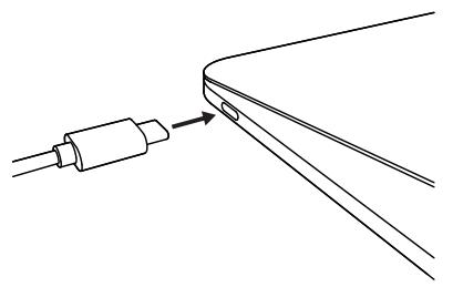
STEP 6: CONNECTION SUCCESSFUL
Note:
www.logitech.com/tune
CUSTOMIZABLE OPTIONS
- Show Mode
- Auto-framing
- Zoom adjustment
- Field of View (90°/78°/65°)
- Image adjustment
- Auto-focus • Disable microphone
- LED on/off for video and audio
STEP 9: (OPTIONAL) MOUNT ON TRIPOD
- Find the 1/4-inch tripod thread on the bottom of the webcam.
DIMENSIONS
WEBCAM:
www.logitech.com/prosupport/mx-brio-705-for-business


- MX BRIO 705 FOR BUSINESS
- CONTENTS
- MOUNT DESIGN OVERVIEW
- STEP 1: WHAT'S IN THE BOX
- STEP 2: DETERMINE MOUNT PLACEMENT
- PLACEMENT TO ALLOW ONE-HANDED CAMERA ADJUSTMENTS (USING MICRO-SUCTION PAD)
- NOTE
- (OPTIONAL) PLACEMENT WITHOUT THE MICRO-SUCTION PAD
- STEP 3: MOUNT ADAPTER REMOVAL AND CLEANING
- STEP 4: ATTACH CAMERA TO THE MOUNT
- STEP 5: CONNECT THE WEBCAM VIA USB-C & GET STARTED
- STEP 6: SUCCESSFUL CONNECTION
- STEP 7: SHOW MODE
- IF MOUNT IS SECURED WITH MICRO-SUCTION PAD
- IF THE MOUNT IS NOT SECURED WITH THE MICRO-SUCTION PAD
- STEP 8: LOGI TUNE
- ADJUSTABLE OPTIONS
- STEP 9: (OPTIONAL) ATTACH TO A TRIPOD
- FOR PLACEMENT ON A TRIPOD (NOT INCLUDED)
- DIMENSIONS
- WEBCAM
- MOUNTING CLIP
- PRODUCT AT A GLANCE
- MX BRIO 705 FOR BUSINESS FRONT VIEW WITH FUNCTION INDICATORS
- CUSTOMIZABLE OPTIONS
- STEP 9: (OPTIONAL) MOUNTING ON A TRIPOD
- PRODUCT OVERVIEW
- FRONT VIEW OF MX BRIO 705 FOR BUSINESS WITH FUNCTION INDICATORS
- STEP 3: REMOVAL AND CLEANING OF THE MOUNTING ADAPTER
- STEP 4: MOUNTING THE CAMERA
- STEP 5: CONNECTING THE WEBCAM VIA USB-C AND GETTING STARTED
- STEP 6: CONNECTION SUCCESSFUL
- STEP 9: (OPTIONAL) TRIPOD MOUNTING
- STEP 4: ATTACH THE CAMERA TO THE MOUNT
- STEP 5: CONNECT THE WEBCAM VIA USB-C AND START USING IT
- PRODUCT COMPONENTS
- STEP 5: CONNECT THE WEBCAM VIA USB-C AND START
- FRONT VIEW MX BRIO 705 FOR BUSINESS WITH FUNCTION OVERVIEW
- STEP 3: REMOVE AND CLEAN THE MOUNT ADAPTER
- STEP 5: CONNECT THE WEBCAM VIA USB-C AND GET STARTED
- STEP 9: (OPTIONAL) MOUNT ON A TRIPOD
- STEP 6: CONNECTION
- MX BRIO 705 FOR BUSINESS SET FRONT VIEW WITH FUNCTION INDICATORS
- STEP 3: MOUNTING THE ADAPTER AND CLEANING
- GET TO KNOW THE PRODUCT
- STEP 3: REMOVING AND CLEANING THE MOUNTING ADAPTER
- STEP 6: CONNECTION COMPLETE
- REGISTER YOUR PRODUCT
- MX BRIO 705 FOR BUSINESS FRONT VIEW AND FEATURES
- STEP 5: CONNECT THE WEBCAM VIA THE USB-C PORT AND START
- STEP 6: CONNECTION ESTABLISHED
- STEP 9: (OPTIONAL) ATTACH TO TRIPOD
- ADJUSTMENT OPTIONS
- CUSTOMIZABLE SETTINGS
- DEVICE DESCRIPTION
- STEP 3: DISASSEMBLY AND CLEANING OF THE MOUNTING ADAPTER
- STEP 4: MOUNTING THE CAMERA TO THE BRACKET
- STEP 5: CONNECT THE WEBCAM VIA USB-C AND START WORKING
- STEP 9 (OPTIONAL) MOUNTING ON A TRIPOD
- WEB CAMERA
- STEP 5: CONNECT THE WEBCAM WITH THE USB-C CONNECTOR AND GET TO WORK
- PRODUCT DESCRIPTION
- STEP 5: CONNECTING THE WEBCAM VIA USB-C AND STARTING UP
- STEP 9: (OPTIONAL) ATTACHING TO A TRIPOD
- STEP 5: CONNECTING THE WEBCAM VIA USB-C AND STARTING OPERATION
- STEP 3. REMOVING AND CLEANING THE MOUNTING ADAPTER
- STEP 5. CONNECT THE WEBCAM VIA USB-C AND START USING IT
- STEP 6. SUCCESSFUL CONNECTION
- OPTIONAL SETTINGS
- STEPS. (OPTIONAL) MOUNTING TO THE STAND
- MX BRIO 705 FOR BUSINESS" FRONT VIEW WITH FUNCTION INDICATORS
- OPERATION. REMOVING AND CLEANING THE MOUNTING ADAPTER
- OPERATION. ATTACHING THE CAMERA TO THE MOUNT
- OPERATION. CONNECTING THE CAMERA WITH USB-C AND STARTING WORK
- OPERATION. ESTABLISHING A SUCCESSFUL CONNECTION
- CUSTOMIZATION OPTIONS
- OPERATION. (OPTIONAL) MOUNTING TO A STAND
- GET TO KNOW YOUR PRODUCT
- STEP 3. REMOVING AND CLEANING THE TRIPOD ADAPTER
- STEP 4. MOUNTING THE CAMERA TO THE TRIPOD
- STEP 5. CONNECT THE WEBCAM VIA USB-C AND START
- IF THE MOUNT IS NOT ATTACHED WITH THE MICRO-SUCTION CUP
- STEP 9. (OPTIONAL) ATTACH TO TRIPOD
- GET TO KNOW YOUR DEVICE
- FRONT VIEW OF THE MX BRIO 705 FOR BUSINESS DEVICE WITH FUNCTION INDICATORS
- STEP: BOX CONTENTS
- STEP: DETERMINE MOUNT POSITION
- (OPTIONAL) SETUP WITHOUT THE VACUUM MICRO-PAD
- STEP: REMOVING AND CLEANING THE MOUNT ADAPTER
- STEP 4: ATTACHING THE CAMERA TO THE MOUNT
- STEP 5: CONNECTING THE WEBCAM VIA USB-C CABLE AND STARTING
- ADJUSTABLE FEATURES
- FOR MOUNTING ON A TRIPOD (NOT INCLUDED)
- FRONT VIEW OF MX BRIO 705 FOR BUSINESS DEVICE WITH FUNCTION LABELS
- MOUNT OVERVIEW
- STEP 1: PACKAGE CONTENTS
- STEP 2: DETERMINING THE BRACKET POSITION
- IT IS POSITIONED TO ALLOW ONE-HANDED CAMERA ADJUSTMENTS (USING THE MICRO-SUCTION PAD)
- (OPTIONAL) INSTALLATION WITHOUT THE MICRO-SUCTION PAD
- STEP 3: REMOVING AND CLEANING THE MOUNT ADAPTER
- KNOW THE PRODUCT
- (OPTIONAL) SETUP WITHOUT THE MICRO SUCTION PAD
- STEP 5: ESTABLISHING THE WEBCAM CONNECTION VIA USB-C AND STARTING
- IF THE MOUNT IS NOT ATTACHED WITH THE MICRO SUCTION PAD
- STEP 9: ATTACHING TO THE STAND (OPTIONAL)
- GET FAMILIAR WITH THE PRODUCT
- STEP 4: ATTACHING THE CAMERA TO THE SUPPORT
- STEP 5: CONNECTING THE WEB CAMERA VIA USB-C AND STARTING USE
- STEP 4: ATTACHING THE CAMERA TO THE MOUNTING ADAPTER
- STEP 5: CONNECTING AND STARTING THE WEB CAMERA WITH USB-C
- FIELD OF VIEW
- KNOW YOUR PRODUCT
- STEP 3: REMOVING AND CLEANING THE BASE ADAPTER
- STEP 4: ATTACHING THE WEBCAM TO THE BASE
- TO PLACE ON A TRIPOD (NOT INCLUDED)
- SPECIFICATIONS
- STEP 5: CONNECT THE WEBCAM VIA USB-C & START
- STEP 9: (OPTIONAL) MOUNT ON TRIPOD
Brand : LOGITECH
Model : MX Brio
Category : Webcam