
CV 85 2 RS - Industrial vacuum cleaner KARCHER - Free user manual and instructions
Find the device manual for free CV 85 2 RS KARCHER in PDF.
| Product type | Self-propelled industrial vacuum sweeper for carpets |
| Brand | KARCHER |
| Model | CV 85 2 RS |
| Nominal voltage | 36 V |
| Battery capacity | 105 Ah (5h) |
| Average power consumption | 1475 W |
| Working width | 800 mm |
| Rotary brush diameter | 100 mm |
| Rotary brush rotation speed | 1750 rpm |
| Side brush diameter | 300 mm |
| Side brush rotation speed | 85 rpm |
| Suction air flow rate | 45 l/s |
| Maximum vacuum pressure | 4.0 kPa |
| Filter bag volume | 35 L |
| Maximum travel speed | 5.6 km/h |
| Maximum permissible slope | 10% |
| Dimensions (L × W × H) | 1330 × 927 × 1285 mm |
| Maximum total weight | 451 kg |
| Sound pressure level | 62 dB(A) |
| Theoretical cleaning area | 3270 m²/h |
| Power supply | 36 V battery (not supplied) |
| Main functions | Carpet vacuuming and sweeping, self-propelled |
| Safety devices | Emergency stop button, safety pedal, electric parking brake |
| Routine maintenance | Emptying filter bag, cleaning brushes, checking acid level (wet battery) |
| Spare parts and repairability | Original parts available via KARCHER after-sales service or website www.kaercher.com |
Frequently Asked Questions - CV 85 2 RS KARCHER
User questions about CV 85 2 RS KARCHER
0 question about this device. Answer the ones you know or ask your own.
Ask a new question about this device
Download the instructions for your Industrial vacuum cleaner in PDF format for free! Find your manual CV 85 2 RS - KARCHER and take your electronic device back in hand. On this page are published all the documents necessary for the use of your device. CV 85 2 RS by KARCHER.
USER MANUAL CV 85 2 RS KARCHER
natural_image
Exterior view of a white Karcher cleaning robot with black and white casing (no visible text or symbols)| Deutsch | 3 |
| English | 11 |
| Français | 19 |
| Italiano | 27 |
| Nederlands | 36 |
| Español | 44 |
| Português | 53 |
| Dansk | 61 |
| Norsk | 69 |
| Svenska | 77 |
| Suomi | 85 |
| Ελληνικά | 93 |
| Türkçe | 102 |
| Русский | 110 |
| Magyar | 119 |
| Čeština | 127 |
| Slovenščina | 135 |
| Polski | 143 |
| Româneşte | 152 |
| Slovenčina | 161 |
| Hrvatski | 169 |
| Srpski | 178 |
| Български | 186 |
| Eesti | 195 |
| Latviešu | 203 |
| Lietuviškai | 211 |
| Українська | 219 |
Register and win! www.kaercher.com

natural_image
Technical diagram of a mechanical assembly with labeled components and connections (no readable text or symbols)natural_image
Line drawing of a cleaning or dust removal machine on a flatbed platform (no text or symbols)natural_image
Technical line drawing of a vehicle's front wheel assembly with visible components and mounting brackets (no text or labels)natural_image
Technical line drawing of a vehicle chassis with labeled components (no text or symbols present)natural_image
Technical line drawing of a mechanical assembly with labeled component (no text or symbols present)1 Schraube
natural_image
Symmetrical mechanical component diagram with no visible text or symbolsnatural_image
Technical line drawing of a mechanical assembly with no visible text or symbols1 Schraube

S. Reiser
Head of Approbation
71364 Winnenden (Germany)
Tel.: +49 7195 14-0
Fax: +49 7195 14-2212

Please read and comply with these original instructions prior to the ini-
tial operation of your appliance and store them for later use or subsequent owners.
Contents
| Safety instructions | EN - | 1 |
| Function | EN - | 1 |
| Proper use | EN - | 1 |
| Environmental Protection, Disposal | EN - | 1 |
| Operating and Functional Elements | EN - | 2 |
| Before Commissioning | EN - | 3 |
| Operation | EN - | 4 |
| Transport | EN - | 5 |
| Storage | EN - | 5 |
| Maintenance and care | EN - | 5 |
| Faults | EN - | 7 |
| Accessories | EN - | 7 |
| Specifications | EN - | 8 |
| Spare parts | EN - | 8 |
| Warranty | EN - | 8 |
| CE declaration | EN - | 8 |
Safety instructions
Before using the machine for the first time, read and observe these operating instructions and the accompanying brochure:
Safety information for sweepers and vacuum sweepers, 5.956-249.
The machine has been approved for use on surfaces with gradients of up to 10%.
Safety Devices
Safety devices serve to protect the user and must not be rendered inoperational or their functions bypassed.
Emergency-stop button
To put all functions out of operation immediately: Press emergency-stop button.
Safety pedal
The drive can only be activated when the operated keeps the pedal depressed with the foot.
Symbols
The following symbols are used in this operating manual:
⚠️ Danger
Immediate danger that can cause severe injury or even death.
⚠ Warning
Possible hazardous situation that could lead to severe injury or even death.
Caution
Possible hazardous situation that could lead to mild injury to persons or damage to property.
Function
The device is meant for vacuuming carpeted surfaces. The dirt is loosened from the carpet by brushing; it is then vacuumed and collected in a filter bag.
- A working distance of 850 mm will improve the efficiency when you are using the appliance for a long period.
– The appliance is self-driven. - The batteries can be charged using a charger connected to a 230 V socket.
- Battery and charger are not part of the scope of delivery and need to be ordered separately.
Note
The appliance can be equipped with various accessories depending on the cleaning task and the location site.
Please request our catalogue or visit us on the Internet at www.kaercher.com.
Proper use
Use this appliance only as directed in these operating instructions.
- The appliance should only be used for vacuuming carpeted floors.
- The appliance may only be equipped with original accessories and spare parts.
- The application temperature ranges from +5°C to +40°C.
- The machine should not be used on surfaces that are sensitive to pressure. Please consider the allowed load per surface unit of the floor. Details of load per surface unit can be found in the technical data.
- The appliance is not suited for the use in potentially explosive environments.
- The machine is not suitable for vacuuming dust which endangers health.
- Reactive metal dusts (for e.g. aluminium, magnesium, zinc) can form explosive gases when they come in contact with highly alkaline or acidic detergents.
Environmental Protection, Disposal

The packaging materials are recyclable. Please do not throw packaging in the domestic waste but pass it on for recycling.
Old units contain valuable recyclable materials. Batteries, oil and similar substances may not be released into the environment. Therefore please dispose of old units through suitable collection systems.
Notes about the ingredients (REACH)
You will find current information about the ingredients at:
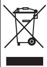
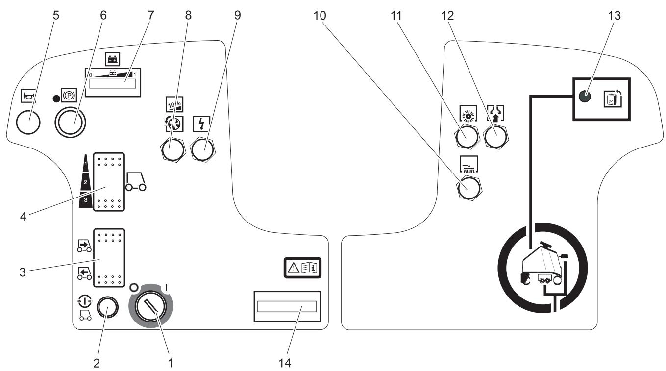
Operating and Functional Elements
1 Battery socket
2 Battery
3 Locking the battery insert
4 Battery insert
5 Filter bag
6 Filter sack
7 Connection nozzle
8 Inner lid of filter chamber
9 Lid of filter chamber
10 Unlocking lever for immobilising brake
11 Side brushes
12 Brush / suction head
13 Raise/ lower lever for brushing/ vacuuming unit
14 Drive pedal
15 Standing area for operator
16 Safety pedal
17 Battery cover
18 Locking screw for battery cover
19 Steering wheel
20 Operator console

1 Key switch
2 Unlocking button
3 Driving direction switch
4 Speed button
5 Horn
6 Emergency-stop button
7 Battery control display
8 Fuse for traction drive
9 Fuse for controls
10 Fuse of side-brush drive
11 Fuse of roller brush drive
12 Fuse for suction turbine
13 Display 'Filter bag is full'
14 Operating hour counter
Before Commissioning
Batteries
Please observe the following warning notes when handling batteries:
| Observe the directions on the battery, in the instructions for use and in the vehicle operating instructions | |
| Wear eye protection | |
| Keep children away from acid and batteries | |
| Danger of explosion | |
| Fire, sparks, naked flames and smoking must be strictly avoided |
| Danger of chemical burns | |
| First aid | |
| Warning note | |
| Disposal | |
| Do not throw the battery into the regular waste |
⚠️ Danger
Danger of explosion. Do not put tools or similar on the battery, i.e. on the terminal poles and cell connectors.
Risk of injury. Ensure that wounds never come into contact with lead. Always clean your hands after having worked with batteries.
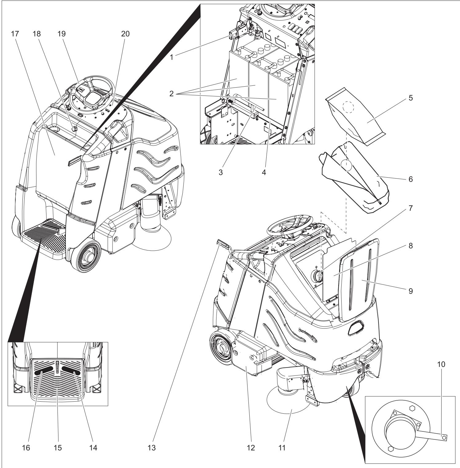
Insert batteries and connect
→ Unscrew the locking screw of the battery cover.
→ Tilt the battery cover backwards.
→ Push the lock of the battery insert towards the left and tilt it downward.
→ Pull the battery insert towards the rear.
→ Place the batteries in the trough of the battery insert.
→ Connect poles with the enclosed connecting cables.
Pay attention to correct poles.
→ Connect the connection cable to the free battery poles (+) and (-).
→ Push the battery insert towards the front.
→ Lock in the battery insert lock.
⚠ Warning
⚠ Warning
Charge the battery before commissioning the machine.
Charging battery
→ If the light bars on the left side of the battery display are blinking, then drive the device directly to the charging station; avoid steep climbing while doing so.
⚠️ Danger
Risk of electric shock. Observe supply network and fuse protection - see "Charger". Only use the charger in dry rooms with sufficient ventilation!
Note
Average charging time is approx. 10 hours. The recommended chargers (matching the batteries used) are regulated electronically and will automatically switch off the charging process.
⚠️ Danger
Danger of explosion. Wet batteries can only be charged with opened battery cover.
→ Unscrew the locking screw of the battery cover.
→ Tilt the battery cover backwards.
→ Remove battery plug and join it to the charging cable.
→ Connect the charger to the mains and turn it on.
After charging
→ Switch off the charger and remove the plug from the socket.
→ Pull the battery cable from the charger cable and connect it to the machine.
→ Tilt the battery cover towards the front and tighten the locking screw.
Further, in case of maintenance-free batteries (wet batteries):
→ Add distilled water one hour before the charging process comes to an end; follow the correct acid level. There are corresponding indicators on the battery. At the end of the charging process, all cells must gas.
⚠️ Danger
Danger of causticization!
- Adding water to the battery in its discharged state can cause the acid to leak.
- Use safety glasses while handling battery acid and follow the safety instructions to avoid personal injury or damage to clothes.
- Should the acid spray on to the skin or clothes, rinse immediately with lots of water.
Caution
Risk of damage!
- Use only distilled or desalinated water (EN 50272-T3) for filling the battery.
- Do not add any substances (so-called performance improving agents), else warranty claims will not be entertained.
Recommended batteries
| Battery | Order No. |
| 3 x 12V/105 A, maintenance-free (Gel) | 6.654-141.0 |
Recommended chargers
| Charger | Order No. |
| 36V, for maintenance-free batteries | 6.654-229.0 |
Batteries and chargers are available in specialised stores.
Maximum battery dimensions
| Length | Width | Height |
| 406 mm | 533 mm | 432 mm |
Please follow these instructions if you are using wet batteries:
- It is necessary to conform to the maximum battery dimensions.
- The battery cover needs to be opened while charging wet (maintenance-free) batteries.
- While charging wet batteries, follow the specifications of the battery manufacturer.
Removing the batteries
→ Unscrew the locking screw of the battery cover.
→ Tilt the battery cover backwards.
→ Push the lock of the battery insert towards the left and tilt it downward.
→ Pull the battery insert towards the rear.
→ Clamp off the minus pole of the battery.
→ Clamp off the remaining cables from the battery.
→ Remove the batteries.
→ Dispose of the used batteries according to the local provisions.
Pushing the device
While standing, the device is protected against rolling off with the help of an electrical immobilising brake. To push the device, you need to first unlock the immobilising brake.
→ Press the unlocking lever downward to unlock the immobilising brake.
⚠️ Danger
Risk of accident if the device rolls off. Apply the immobilising brake again immediately after finishing pushing the machine by pushing the unlocking lever upward.
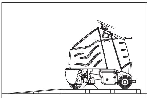
Unloading
Note
Take the foot off the accelerator pedal, press the emergency-stop button to immediately deactivate all functions and turn the key switch to the "0" position.
→ Loosen the screws and remove the wooden cage.
→ Cut plastic packing belt and remove foil.
→ Loosen the fixing at the wheels.
→ Place the enclosed wooden board at the back of the appliance on the pallet as a ramp and attach with screws.
natural_image
Line drawing of a cleaning or dust removal machine on a flatbed platform (no text or symbols)→ Remove both blocks from behind the rear wheels.
→ Open the battery cover and remove the steering wheel.
→ Insert the steering wheel and straight-align the front wheel.
→ Pull out the steering wheel, align and insert back.
→ Fasten the steering wheel using enclosed nut.
→ Insert the cover in the steering wheel.
→ In appliances without battery: Install batteries.
→ Connect the battery plug to the appliance.
→ Get on to the standing area and keep the safety pedal depressed with the left foot.
→ Release emergency-stop button by turning.
→ Set main switch to "1".
→ Set the drive direction to backwards using the drive direction button at the operator console.
→ Select the smallest speed range using the speed button.
→ Press the unlocking key.
→ To drive, press the accelerator pedal carefully and drive down slowly from the palette.
→ Set main switch to "0".
→ Attach hubcaps to the rear wheels.
Operation
Note
Take the foot off the accelerator pedal, press the emergency-stop button to immediately deactivate all functions and turn the key switch to the "0" position.
→ Carry out maintenance jobs "daily before starting work" (see section "Maintenance and Care").
Check immobilizing brake
⚠️ Danger
Danger of accident. The immobilizing brake must always be checked first on an even surface before starting the machine.
→ Set main switch to "0".
→ Press emergency-stop button.
If the appliance can be moved by hand, the parking brake is not engaged.
→ Pull up the reset lever of the parking break.
If the appliance can still be moved by hand, the parking break is defective. Shut down the appliance and call Customer Service.
Brakes
⚠️ Danger
Danger of accident. If the appliance cannot brake adequately while going downhill, press the emergency stop button.
Driving
Carry out the initial trials in an open surface so that you familiarise yourself with the appliance.
⚠️ Danger
Danger of tipping if gradient is too high.
→ The gradient in the direction of travel should not exceed 10%.
Danger of tipping when driving round bends at high speed.
Danger of slipping on wet floors.
→ Drive slowly when cornering.
Danger of tipping on unstable ground.
→ Only use the machine on sound surfaces.
Danger of tipping with excessive sideways tilt.
→ The gradient perpendicular to the direction of travel should not exceed 10%.
→ Get on to the standing area and keep the safety pedal depressed with the left foot.
→ Do not press the accelerator pedal.
→ Release emergency-stop button by turning.
→ Set main switch to "1".
→ Set the drive direction using the drive direction button at the operator console.
→ Select speed range using the speed button (3 stages).
→ Press the unlocking key.
→ Press the accelerator carefully to drive.
Note
The drive direction can also be changed during the drive. You can thus clean very dirty surfaces by driving back and forth a couple of times.
Overload
In case of overloading, the drive motor automatically switches off after a certain period.
→ Allow machine to cool down at least for 15 minutes.
→ Press again the drive fuse on the operating panel.
Vacuuming
→ While vacuuming bulky waste, remove wires and threads from the area to be vacuumed to avoid these getting stuck in the brushes.
⚠ Warning!
Risk of damage to the floor covering. Do not operate the appliance on the spot. Only raise and lower suction/brush head while driving. Do not stop with lowered brush/suction head.
→ Move downward the lever for raising / lowering brushing/ vacuuming unit - side-brush and brushing/ vacuuming head will be lowered.
Start brush drive and suction turbine as soon as the brush-vacuuming unit is lowered
→ Press accelerator pedal and drive to the surface to be cleaned.
Note
Speed level 2 is recommended for cleaning. Speed stage 3 is only meant for driving during transportation.
→ Select the smallest speed range using the speed button.
Vacuuming completed
→ Move upward the lever for raising / lowering brushing/ vacuuming unit - side-brush and brushing/ vacuuming head will be raised and switched off.
Shutting down
→ Park the machine on an even surface.
→ Turn key to "0" and remove it.
→ Carry out maintenance jobs "daily/ after finishing work" (see section "Maintenance and Care").
→ Secure the machine with wheel chock(s) to prevent it from rolling away.
Transport
⚠️ Danger
Risk of injury! When loading or unloading the machine, it may only be operated on gradients of max. 10%. Drive slowly.
Caution
Risk of injury and damage! Observe the weight of the appliance when you transport it.
→ Remove vacuum bar, brushes and spray guard from the device.
→ When transporting in vehicles, secure the appliance according to the guidelines from slipping and tipping over.
natural_image
Technical line drawing of a vehicle's front wheel assembly with visible components and mounting base (no text or labels)1 Fastening points
Storage
Caution
Risk of injury and damage! Note the weight of the appliance in case of storage.
This appliance must only be stored in interior rooms.
Maintenance and care
⚠️ Danger
Risk of injury! Before carrying out any tasks on the machine, set the main key to "0" and remove it. Pull out the battery plug.
Maintenance schedule
Daily
Before starting working:
→ Check tyre status.
→ Check whether the inner lid of the filter chamber.
→ Check suction hose for blockages; clean if required.
→ Check the inserts of the suction hose for leaks.
→ Check safety pedal, accelerator pedal and steering wheel for correct functioning.
→ Check acid level in wet batteries; refill distilled water, if required.
→ Check filled level of the filter bag; replace, if required.
After finishing working:
→ Clean brushes and check for wear and tear.
The bristles are worn out when they reach the length of the yellow bristles.
→ Clean the outside of the appliance with a damp cloth which has been soaked in mild detergent.
→ Check device externally for damage.
→ Charge the batteries.
Every 50 operating hours
→ Clean upper side of the batteries.
→ Check acid density in wet batteries.
→ Check battery cable for correct positioning.
Every 100 operating hours
→ Clean battery room and battery casing.
→ Check tension of the drive chain (see "Maintenance tasks").
→ Check drive belt for wear and tear.
→ Check alignment of the brush/ vacuum head.
Every 200 operating hours
→ Check immobilising brake. *
→ Check chains, ropes and deflection pulleys for raising the brushing/ vacuuming head and the side-brush for wear and tear and tension. *
→ Check carbon brushes and commutators of all motors for wear and tear. *
→ Check tightening device of steering chains. *
Maintenance Works
Maintenance contract
To ensure a reliable operation of the appliance maintenance contracts can be concluded with the competent Kärcher sales office.
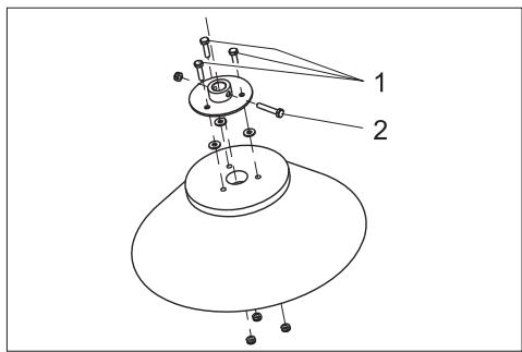
Replacing the filter bag
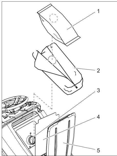
1 Filter bag
2 Filter sack
3 Connection nozzle
4 Inner lid of filter chamber
5 Lid of filter chamber
→ Open both the lids of the filter chamber.
→ Open the zip of the filter sack.
→ Pull out the full filter bag from the connecting nozzle.
→ Remove and dispose off the filter bag from the filter sack.
→ Clean filter chamber if required.
→ Pull out the filter bag from the nozzle and shake it off or clean it, if required.
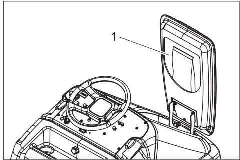
1 Storage compartment for filter bags
→ Remove a new filter bag from the storage compartment in the lid and insert it in the filter sack.
→ Push the opening of the filter bag over the connection nozzle.
→ Close the zip of the filter sack.
→ Close both the lids of the filter chamber.
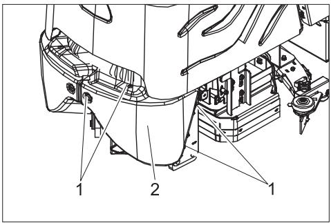
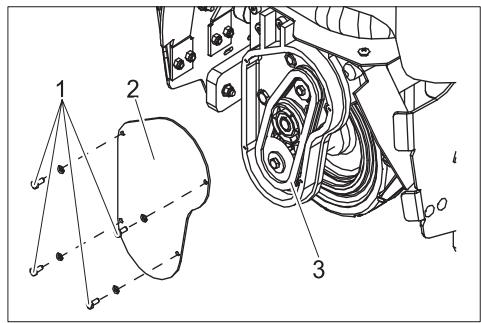
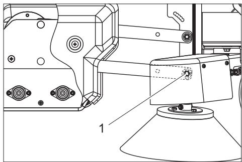
Replacing the brush rollers
natural_image
Technical line drawing of a mechanical assembly with labeled component (no text or symbols present)1 Screw
→ Remove both the screws of the cover on the right side of the device.
→ Remove cover.

1 Screw
2 Bearing plate
→ Loosen the screws for fastening the bearing plate.
→ Pull out the bearing plate.
→ Pull out the brushes.
natural_image
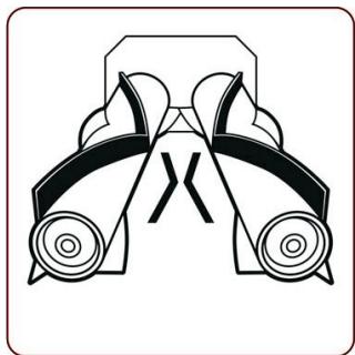
Symmetrical mechanical component diagram with no visible text or symbols→ Insert new brushes and turn till the towing arm locks in. The arrangement of the bristles should be as shown in the above figure.
→ Replace the bearing plate and cover.
Checking the alignment of brush/ vacuum head.
→ Drive the device on a hard, smooth floor (not a carpet).
→ Operate the device with lowered brushing/vacuuming head at one place for 30 seconds. (press the accelerator slowly so that the brushes work without the device moving forward).
→ Raise the brushing/ vacuuming head and drive forward for approx. 1 m.
→ The brushes have left a pattern on the floor. Evaluate the pattern according to the diagram shown below:
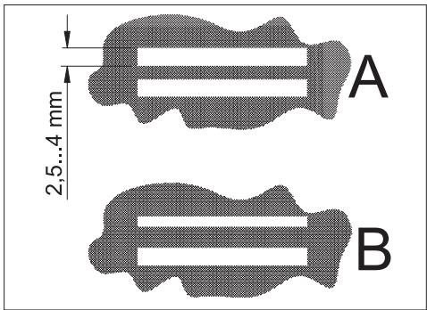
A Both the brushes generate a marking that is equal in width - the brushing/vacuuming head is aligned parallel to the floor.
B Brushes generate markings of various widths - the brush/ vacuuming head needs to be aligned.
Adjusting the alignment of brush/ vacuum head.

natural_image
Technical line drawing of a mechanical assembly with no visible text or symbols1 Screw
→ Loosen the screw on both the sides, insert in the long hole and tighten it again.
- To increase the contact area of the rear brush - move the screw forward.
- To increase the contact area of the front brush - move the screw backward.
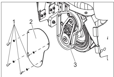
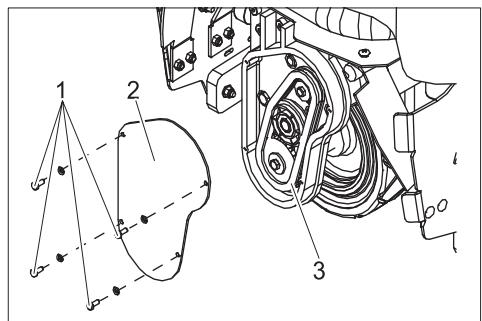
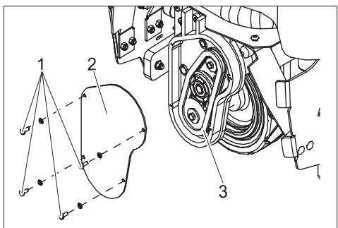
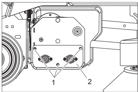
Replacing the side-brushes

1 Fastening screw for flange
2 Fastening screw for brush
→ Turn out the fastening screw for the flange and pull out the brush along with the flange from the drive shaft.
→ Turn out the fastening screw for the flange and pull out the brush along with the flange from the drive shaft.
→ Turn out the fastening screws of the brush and separate the brush from the flange.
→ Install new brush in reverse sequence.
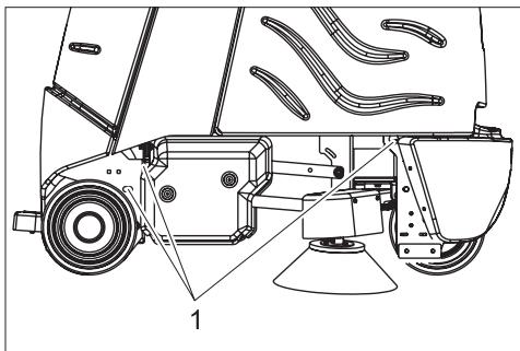
Checking the drive chain
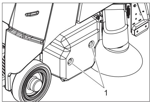
1 Screw
2 Front panel
→ Loosen screws.
→ Remove front panel.
1 Screw
2 Cover
3 Drive chain
→ Loosen screws.
→ Remove the lid.
→ Check the chain drive and pinion for wear.
Faults
⚠️ Danger
Risk of injury! Before carrying out any tasks on the machine, set the main key to "0" and remove it. Pull out the battery plug. In case of faults that cannot be remedied using the table below please contact the customer service.
| Fault | Remedy | By whom |
| Appliance cannot be started | Insert the battery plug on the device. | Operator |
| Release emergency-stop button by turning. | Operator | |
| Battery capacity exhausted; recharge battery. | Operator | |
| Check battery cable for correct sitting. | Operator | |
| Check battery cable for corrosion; clean, if required. | Operator | |
| Device does not drive or drives only slowly | Press the unlocking key. | Operator |
| Reset fuse of traction drive | Operator | |
| Deactivate immobilising brake; press the unlocking lever upward to activate it. | Operator | |
| Release accelerator pedal, turn the key switch to "0", turn the key switch to "1", press the safety pedal, press unlocking key, press accelerator pedal. | Operator | |
| Control is overheatedSwitch off device and let it cool down. | Operator | |
| Battery capacity exhausted; recharge battery. | Operator | |
| Device does not brake | Deactivate immobilising brake; press the unlocking lever upward to activate it. | Operator |
| Brushes in brush/ vacuum head are not working | Reset fuse of brush roller drive. | Operator |
| Check the brushes for blockage due to foreign particles, remove them if found. | Operator | |
| Side-brush is not working | Reset fuse of side-brush drive. | Operator |
| Brushes are rotating slowly | Battery capacity exhausted; recharge battery. | Operator |
| Suction turbine is not working | Reset fuse of suction turbine. | Operator |
| Battery capacity exhausted; recharge battery. | Operator | |
| Filter bag is full; the indicator 'filter bag full' glows. Replace filter bag. | Operator | |
| Poor dust suction | Suction hose/ suction channel blocked; clean suction hose/ suction channel. | Operator |
| Battery capacity exhausted; recharge battery. | Operator | |
| Filter bag full; replace filter bag. | Operator |
Accessories
| Description | Part no.: |
| Filter bag, 10 pieces | 8.600-121.0 |
| Battery replacement kit consists of: battery trough, cable set, locking set, 2 transport cars | 8.601-121.0 |
| Battery, 12V/105 A, maintenance-free (gel), 3 pieces required | 6.654-141.0 |
| Charger, 36V, for maintenance-free batteries | 6.654-229.0 |
Specifications
| Power | ||
| Nominal voltage | V | 36 |
| Battery capacity | Ah (5h) | 105 |
| Average power consumption | W | 1475 |
| Drive motor output (rated output) | W | 560 |
| Brushes | ||
| Working width | mm | 800 |
| Broad roller brush | mm | 710 |
| Diameter of roller brush | mm | 100 |
| Speed of roller brushes | 1/min | 1750 |
| Output of roller brush drive | W | 570 |
| Diameter of side-brush | mm | 300 |
| Speed of side brush | 1/min | 85 |
| Output of side-brush drive | W | 32 |
| Vacuuming | ||
| Cleaning power, air quantity | l/s | 45 |
| Cleaning power, negative pressure | kPa | 4,0 |
| Suction engine output | W | 550 |
| Volume of filter bag | l | 35 |
| Dimensions and weights | ||
| Drive speed (max.) | km/h | 5,6 |
| Climbing capability (max.) | % | 10 |
| Theoretical surface cleaning performance | m2/h | 3270 |
| Length | mm | 1330 |
| Width | mm | 927 |
| Height | mm | 1285 |
| Permissible overall weight | kg | 451 |
| Transport weight | kg | 376 |
| Surface load | kPa | 544 |
| Values determined as per EN 60335-2-72 | ||
| Vibration total value on arms | m/s2 | <2,5 |
| Vibration total value on feet | m/s2 | <2,5 |
| Uncertainty K | m/s2 | 0,5 |
| Sound pressure level LpA | dB(A) | 62 |
Spare parts
- Only use accessories and spare parts which have been approved by the manufacturer. The exclusive use of original accessories and original spare parts ensures that the appliance can be operated safely and troublefree.
- At the end of the operating instructions you will find a selected list of spare parts that are often required.
- For additional information about spare parts, please go to the Service section at www.kaercher.com.
Warranty
The warranty terms published by the relevant sales company are applicable in each country. We will repair potential failures of your appliance within the warranty period free of charge, provided that such failure is caused by faulty material or defects in manufacturing. In the event of a warranty claim please contact your dealer or the nearest authorized Customer Service centre. Please submit the proof of purchase.
CE declaration
We hereby declare that the machine described below complies with the relevant basic safety and health requirements of the EU Directives, both in its basic design and construction as well as in the version put into circulation by us. This declaration shall cease to be valid if the machine is modified without our prior approval.
Product: Brush vacuum cleaner for carpets Type: 1.011-xxx
Relevant EU Directives
2006/42/EC (+2009/127/EC)
2004/108/EC
Applied harmonized standards
EN 55014-1: 2006
EN 55014-2: 1997 + A1: 2001
EN 60335-1
EN 60335-2-29
EN 60335-2-72
EN 61000-3-2: 2006 + A2: 2009
EN 61000-3-3: 2008
EN 62233: 2008
Applied national standards
The undersigned act on behalf and under the power of attorney of the company management.

71364 Winnenden (Germany)
Phone: +49 7195 14-0
Fax: +49 7195 14-2212

natural_image
Technical line drawing of a cleaning or dust removal vehicle (no text or symbols)natural_image
Technical line drawing of a vehicle's rear wheel assembly with visible components and mounting brackets (no text or symbols)1 Points de fixation
Entreposage
Attention
natural_image
Technical line drawing of a vehicle's internal components, showing dashboard and steering wheel assembly (no text or symbols)natural_image
Technical line drawing of a mechanical assembly with labeled components (no text or symbols present)1 Vis
natural_image
Symmetrical mechanical component diagram with no visible text or symbolsnatural_image
Technical line drawing of a mechanical assembly with no visible text or symbols1 Vis
71364 Winnenden (Germany)
natural_image
Line drawing of a cleaning or dust removal machine on a flatbed platform (no text or symbols)natural_image
Technical line drawing of a vehicle's rear wheel assembly with visible components and mounting brackets (no text or symbols)natural_image
Technical line drawing of a mechanical assembly with labeled component (1), no readable text or symbols present.1 Vite
natural_image
Pure mechanical component diagram without any text, numbers, or symbolsnatural_image
Technical line drawing of a mechanical assembly with no visible text or symbols1 Vite
1 Vite
2 Rivestimento frontale
2006/42/CE (+2009/127/CE)
2004/108/CE
71364 Winnenden (Germany)
Tel.: +49 7195 14-0
Fax: +49 7195 14-2212
natural_image
Line drawing of a mechanical cleaning or dust removal vehicle with no visible text or symbolsnatural_image
Technical line drawing of a vehicle chassis with labeled parts (no text or symbols present)natural_image
Technical line drawing of a vehicle chassis with labeled components (no text or symbols present)natural_image
Technical line drawing of a mechanical assembly with labeled component (no text or symbols present)1 Schroeven
1 Schroeven
2 Lagerschild
natural_image
Pure mechanical component diagram without any text, numbers, or symbolsnatural_image
Technical line drawing of a mechanical assembly with no visible text or symbols1 Schroeven
1 Schroeven
2 Frontpaneel

S. Reiser
Head of Approbation
71364 Winnenden (Germany)
Tel.: +49 7195 14-0
Fax: +49 7195 14-2212
natural_image
Line drawing of a mechanical device with wheels and a flat base (no text or symbols)natural_image
Technical line drawing of a vehicle's rear suspension system with labeled components (no text or symbols present)1 bolsa filtrante
2 saco de filtrado
3 Manguito de empalme
4 Tapa interna del compartimento filtrante
5 Tapa cámara de filtro
→ Abrir ambas tapas del compartimento filtrante.
natural_image
Technical line drawing of a vehicle's internal components, showing dashboard and steering wheel assembly (no text or symbols)1 Compartimento de reserva para bolsas filtrantes
natural_image
Technical line drawing of a mechanical assembly with labeled components (no text or symbols present)1 tornillo
natural_image
Pure mechanical component diagram without any text, numbers, or symbolsnatural_image
Technical line drawing of a mechanical assembly with no visible text or symbols2006/42/CE (+2009/127/CE)
2004/108/CE
71364 Winnenden (Germany)
Tfno.: +49 7195 14-0
Fax: +49 7195 14-2212

Leia o manual de manual original antes de utilizar o seu apare-
natural_image
Technical diagram of a mechanical assembly with labeled components and connections (no readable text or symbols)Desmontar as baterias
natural_image
Line drawing of a mechanical cleaning or dust removal device with no visible text or symbolsnatural_image
Technical line drawing of a vehicle's rear wheel assembly with visible components and mounting base (no text or symbols)1 Pontos de fixação
Armazenamento
Atenção
natural_image
Technical line drawing of a vehicle chassis with labeled components (no text or symbols present)1 Compartimento para sacos de reserva
natural_image
Technical line drawing of a mechanical assembly with labeled components (no text or symbols present)1 Parafuso
natural_image
Pure mechanical diagram of a symmetrical bracket with two wheels and a central cross symbol (no text or labels)natural_image
Technical line drawing of a mechanical assembly with no visible text or symbols1 Parafuso
1 Parafuso
2 Revestimento frontal
→ Desaparafusar parafusos.
→ Retirar revestimento frontal.
2006/42/CE (+2009/127/CE)
2004/108/CE
71364 Winnenden (Germany)
Tel.: +49 7195 14-0
Fax: +49 7195 14-2212

natural_image
Line drawing of a cleaning or dust removal vehicle with no visible text or symbolsnatural_image
Technical line drawing of a vehicle's rear wheel assembly with visible components and mounting brackets (no text or labels)natural_image
Technical line drawing of a vehicle's internal components, showing dashboard, steering wheel, and steering wheel cover (no text or symbols)natural_image
Technical line drawing of a mechanical assembly with labeled parts (no text or symbols present)1 Skrue
1 Skrue
2 Lejeskjold
natural_image
Pure mechanical component diagram without any text, numbers, or symbolsnatural_image
Technical line drawing of a mechanical assembly with no visible text or symbols1 Skrue
2006/42/EF (+2009/127/EF)
2004/108/EF
71364 Winnenden (Germany)
Tlf.: +49 7195 14-0
Fax: +49 7195 14-2212

1 Batterikontakt
2 Batteri
3 Låsing batteriinskyvning
4 Batteriinnskyving
5 Filterpose
6 Filtersekk
7 Tilkoblingsstusser
8 Indre lokk filterkammer
9 Deksel filterkammer
10 Låsehendel parkeringsbremse
11 Sidebørste
12 Børste-/sugehode
13 Hendel senke/heve børste-/sugeenhet
14 Kjørepedal
15 Ståflate for bruker
16 Sikkerhetspedal
17 Batterideksel
18 Låseskrue batterideksel
19 Ratt
20 Betjeningspanel
1 Nøkkelbryter
2 Åpneknapp
3 Kjøreretningsbryter
4 Bryter hastighet
5 Horn
6 Nødstoppknapp
7 Batterikontrollindikator
8 Sikring kjøredrift
9 Sikrig styring
10 Sikring sidebørstedrift
11 Sikring børstevalsedrift
12 Sikring sugevifte
13 Indikator filterpose full
14 Driftstimeteller
Før igangsetting
Batterier
natural_image
Technical diagram of a mechanical assembly with labeled components and connections (no readable text or symbols)natural_image
Line drawing of a cleaning or dust removal vehicle with no visible text or symbolsnatural_image
Technical line drawing of a vehicle's front wheel assembly with visible components and mounting brackets (no text or labels)1 Festepunkter
Lagring
Forsiktig!
natural_image
Technical line drawing of a vehicle's internal components, showing dashboard, steering wheel, and steering wheel cover (no text or symbols)1 Beholderrom for filterposer
natural_image
Technical line drawing of a mechanical assembly with labeled parts (no text or symbols present)1 Skrue
natural_image
Pure mechanical component diagram without any text, numbers, or symbolsnatural_image
Technical line drawing of a mechanical assembly with no visible text or symbols1 Skrue
1 Skrue
2 Frontkledning
1 Skrue
2 Deksel
3 Drivkjede
2006/42/EF (+2009/127/EF)
2004/108/EF
71364 Winnenden (Germany)
Tlf: +49 7195 14-0
natural_image
Line drawing of a cleaning or dust removal vehicle with no visible text or symbolsnatural_image
Technical line drawing of a vehicle's rear wheel assembly with visible components and mounting brackets (no text or labels)1 Fästpunkter
Förvaring
Varning
natural_image
Technical line drawing of a vehicle chassis with labeled components (no text or symbols present)natural_image
Technical line drawing of a mechanical assembly with labeled components (no text or symbols present)1 Skruv
1 Skruv
2 Lagersköld
natural_image
Pure mechanical component diagram without any text, numbers, or symbolsnatural_image
Technical line drawing of a mechanical assembly with no visible text or symbols1 Skruv
1 Skruv
2 Lock
3 Drivkedja
71364 Winnenden (Germany)
Tel.: +49 7195 14-0
Fax: +49 7195 14-2212
→ Laita akut akkukotelon kaukaloon.
natural_image
Line drawing of a cleaning or dust removal vehicle with no visible text or symbolsnatural_image
Technical line drawing of a vehicle's front wheel assembly with visible components and mounting brackets (no text or labels)1 Kiinnityspisteet
Säilytys
Varo
natural_image
Technical line drawing of a vehicle chassis with labeled components (no text or symbols present)natural_image
Technical line drawing of a mechanical assembly with labeled components (no text or symbols present)1 Ruuvi
1 Ruuvi
2 Laakerikilpi
natural_image
Symmetrical mechanical component diagram with no visible text or symbolsnatural_image
Technical line drawing of a mechanical assembly with no visible text or symbols1 Ruuvi
1 Ruuvi
2 Etuverhoilu
→ Irrota ruuvit.
→ Poista etuverhoilu.
71364 Winnenden (Germany)
Puh.: +49 7195 14-0
natural_image
Line drawing of a cleaning or dust removal vehicle with no visible text or symbolsnatural_image
Technical line drawing of a vehicle's rear wheel assembly with labeled components (no text or symbols present)1 Σημεία στερέωσης
Αποθήκευση
Προσοχή
natural_image
Technical line drawing of a vehicle's internal components, showing dashboard, steering wheel, and seat (no text or symbols)natural_image
Technical line drawing of a mechanical assembly with labeled parts (no text or symbols present)1 Bíðα
natural_image
Pure mechanical component diagram without any text, numbers, or symbolsnatural_image
Technical line drawing of a mechanical assembly with no visible text or symbols1 Bíðα

S. Reiser
Head of Approbation
71364 Winnenden (Germany)
Tηλ.: +49 7195 14-0
Φαξ: +49 7195 14-2212

natural_image
Technical diagram of a mechanical assembly with labeled components and connections (no readable text or symbols)natural_image
Line drawing of a cleaning or dust removal vehicle with no visible text or symbolsnatural_image
Technical line drawing of a vehicle chassis with labeled components (no text or symbols present)natural_image
Technical line drawing of a vehicle's internal components, showing dashboard, steering wheel, and steering wheel cover (no text or symbols)natural_image
Technical line drawing of a mechanical assembly with labeled components (no text or symbols present)1 Civata
natural_image
Symmetrical mechanical component diagram with no visible text or symbolsnatural_image
Technical line drawing of a mechanical assembly with no visible text or symbols1 Civata
1 Civata
2 Ön kaplama
→ Civataları sökün.
1 Civata
2 Kapak
3 Tahrik zinciri
71364 Winnenden (Germany)
Tel.: +49 7195 14-0
natural_image
Technical line drawing of a mechanical cleaning or dust removal device (no text or symbols)natural_image
Technical line drawing of a vehicle's rear wheel assembly with labeled parts (no text or symbols present)1 Точки крепления
Хранение
Внимание!
natural_image
Technical line drawing of a car interior frame with labeled component (no text or symbols present)natural_image
Technical line drawing of a mechanical device with labeled components (no text or symbols present)1 Винт
natural_image
Pure mechanical component diagram without any text, numbers, or symbolsnatural_image
Technical line drawing of a mechanical assembly with no visible text or symbols1 Винт
natural_image
Line drawing of a cleaning or dust removal machine on a flatbed platform (no text or symbols)natural_image
Technical line drawing of a vehicle's rear suspension system with labeled components (no text or symbols present)1 Rögzítési pontok
Tárolás
Vigyázat
natural_image
Technical line drawing of a vehicle chassis with labeled component (no text or symbols present)natural_image
Technical line drawing of a mechanical device with labeled components (no text or symbols present)1 Csavar
natural_image
Symmetrical mechanical component diagram with no visible text or symbolsnatural_image
Technical line drawing of a mechanical assembly with no visible text or symbols1 Csavar

S. Reiser
Head of Approbation
71364 Winnenden (Germany)
Tel.: +49 7195 14-0
Fax: +49 7195 14-2212
natural_image
Line drawing of a cleaning or dust removal machine on a flatbed platform (no text or symbols)natural_image
Technical line drawing of a vehicle's front wheel assembly with labeled parts (no text or symbols present)1 Upevňovací body
Ukládání
Pozor
natural_image
Technical line drawing of a mechanical assembly with labeled component (no text or symbols present)1 Šroub
1 Šroub
2 Štít ložiska
natural_image
Symmetrical mechanical component diagram with no visible text or symbolsnatural_image
Technical line drawing of a mechanical assembly with no visible text or symbols1 Šroub
2006/42/ES (+2009/127/ES)
2004/108/ES

S. Reiser
Head of Approbation
71364 Winnenden (Germany)
Tel.: +49 7195 14-0
Fax: +49 7195 14-2212
natural_image
Line drawing of a cleaning or dust removal machine on a flatbed platform (no text or symbols)→ Odstranite klade za obemi zadnjimi kolesi.
→ Odprite pokrov baterije in izvlecite volan.
→ Nataknite volan in sprednje kolo izravnajte naravnost.
→ Snemite volan, izravnajte in ponovno nataknite.
→ Volan pritrdite z obemi priloženimi maticami.
→ Pokrov vtaknite v volan.
→ Pri napravah brez baterije: Vgradite baterijo.
→ Baterijski vtič povežite z napravo.
→ Stopite na stojišče in z levo nogo držite varnostni pedal pritisnjen.
→ Tipko za izklop v sili deblokirajte z obračanjem.
→ Ključno stikalo obrnite na "1".
→ Smer vožnje vzvratno nastavite s stikalom za smer vožnje na upravljalnem pultu.
→ S stikalom za hitrost izberite najmanjše področje hitrosti.
→ Pritisnite tipko za deblokado.
→ Za vožnjo previdno aktivirajte vozni pedal in počasi speljite s palete.
→ Ključno stikalo obrnite na "0".
→ Pokrove koles nataknite na zadnja kolesa.
Obratovanje
Napotek
natural_image
Technical line drawing of a vehicle's front wheel assembly with visible components and mounting brackets (no text or labels)natural_image
Technical line drawing of a mechanical device with labeled components (no text or symbols present)1 Vijak
→ Odstranite oba vijaka pokrova na desni strani stroja.
→ Snemite pokrov.

natural_image
Pure mechanical component diagram without any text, numbers, or symbolsnatural_image
Technical line drawing of a mechanical assembly with no visible text or symbols1 Vijak
→ Voijak obojestransko odvijte, premaknite v podolgovato luknjo in ponovno privijte.
- Povečajte površino zadnje krtače - vijake potisnite naprej.
- Povečajte površino sprednje krtače -vijake potisnite nazaj.
Menjava stranske krtače

1 Vijak
2 Čelna obloga
→ Izvijte vijake.
→ Snemite čelno oblogo.

1 Vijak
2 Pokrov
3 Pogonska veriga
→ Izvijte vijake.
→ Snemite pokrov.
→ Preverite obrabo pogonske verige in gonilnega vretena.
Motnje
⚠️ Nevarnost
Nevarnost poškodb! Pred vsemi deli na stroju obrnite ključno stikalo na "0" in ključ izvlecite. Izvlecite baterijski vtič.
2006/42/ES (+2009/127/ES)
2004/108/ES
71364 Winnenden (Germany)
Tel.: +49 7195 14-0
Zalecane akumulatory
natural_image
Line drawing of a cleaning or dust removal vehicle with visible blade and wheel (no text or symbols)natural_image
Technical line drawing of a vehicle's rear wheel assembly with visible components and mounting base (no text or symbols)1 Punkty mocowania
Przechowywanie
Uwaga
natural_image
Technical line drawing of a vehicle's internal components, showing dashboard, steering wheel, and battery cover (no text or symbols)natural_image
Technical line drawing of a mechanical assembly with labeled parts (no text or symbols present)1 Śruba
natural_image
Pure mechanical component diagram without any text, numbers, or symbolsnatural_image
Technical line drawing of a mechanical assembly with no visible text or symbols1 Śruba
2006/42/WE (+2009/127/WE)
2004/108/WE
71364 Winnenden (Germany)
tel.: +49 7195 14-0
faks: +49 7195 14-2212

1 Fişa accumulator
2 Acumulator
17 Capac accumulator
natural_image
Line drawing of a cleaning or dust removal vehicle with no visible text or symbolsnatural_image
Technical line drawing of a vehicle's rear wheel assembly with visible components and mounting base (no text or symbols)1 Puncte de fixare
Depozitarea
Atentie
natural_image
Technical line drawing of a vehicle's internal components, showing dashboard, steering wheel, and battery cover (no text or symbols)natural_image
Technical line drawing of a mechanical assembly with labeled parts (no text or symbols present)1 Şurub
natural_image
Pure mechanical component diagram without any text, numbers, or symbolsnatural_image
Technical line drawing of a mechanical assembly with no visible text or symbols1 Şurub
1 Şurub de fixare a flanşei
2 Şurub de fixare a periei
1 Şurub
2 Capac
3 Lanț de transmisie
Directive EG respectate:
2006/42/CE (+2009/127/CE)
2004/108/CE
Norme armonizate utilize:
EN 55014-1: 2006
EN 55014-2: 1997 + A1: 2001
EN 60335-1
EN 60335-2-29
EN 60335-2-72
EN 61000-3-2: 2006 + A2: 2009
EN 61000-3-3: 2008
EN 62233: 2008

S. Reiser
Head of Approbation
71364 Winnenden (Germany)
Tel.: +49 7195 14-0
Fax: +49 7195 14-2212
Obsah
natural_image
Line drawing of a mechanical cleaning or dust removal vehicle with no visible text or symbols→ Spoza oboch zadných kolies odstráňte špalíky.
→ Otvorte kryt batérie a vyberte volant.
→ Nasad'te volant a nastavte predné koleso do priamej polohy.
→ Volant potiahnite, vyrovnajte a opät' nasad'te.
→ Volant upevnite priloženou skrutkou.
→ Nasad'te kryt do volantu.
→ U strojov bez batérie: Vložte batériu.
→ Zástrčku batérie spojte so strojom.
→ Nastúpte na plochu pre státie a l'avou nohou potlačte a držte bezpečnostný pedál.
→ Tlačidlo núdzového vypnutia odblokujte otočením.
→ Kl'účový spínač nastavte do polohy „1“.
→ Pomocou prepínača smeru jazdy na ovládacom paneli nastavte smer jazdy.
→ Zvol'te so spínačom rýchlosti najnižší rozsah rýchlosti.
→ Stlačte odblokovacie tlačidlo.
→ Použite opatrne pedál jazdy a pomaly zídte dole z palety.
→ Kl'účový spínač nastavte do polohy „0“.
→ Kryty kolies nasuňte na zadné kolesá.
Prevádzka
Upozornenie
natural_image
Technical line drawing of a vehicle's front wheel assembly with visible components and mounting brackets (no text or labels)1 Miesta upevnenia
Uskladnenie
Pozor
natural_image
Technical line drawing of a mechanical assembly with labeled component (no text or symbols present)1 Skrutka
→ Uvoľnite obe skrutky na kryte na pravej strane zariadenia.
→ Kryt odoberte.

natural_image
Pure mechanical component diagram without any text, numbers, or symbolsnatural_image
Technical line drawing of a mechanical assembly with no visible text or symbols1 Skrutka
1 Skrutka
2 veko
3 Ret'az pohonu
2006/42/ES (+2009/127/ES)
2004/108/ES
Uplatňované harmonizované normy:
EN 55014-1: 2006
EN 55014-2: 1997 + A1: 2001
EN 60335-1
EN 60335-2-29
EN 60335-2-72
EN 61000-3-2: 2006 + A2: 2009
EN 61000-3-3: 2008
EN 62233: 2008
71364 Winnenden (Germany)
Tel: +49 7195 14-0
Fax: +49 7195 14-2212

Prije prve uporabe Vašeg uređaja pročitajte ove originalne
1 Akumulatorski utikač
2 Akumulator
3 Zapor odjeljka akumulatora
→ Akumulatore postavite u korito odjeljka.
→ Polove spojite priloženim spojnim kabelima.
⚠ Upozorenje
Pazite na pravilno spajanje polova.
natural_image
Line drawing of a cleaning or dust removal vehicle with no visible text or symbolsnatural_image
Technical line drawing of a vehicle's rear wheel assembly with visible components and mounting base (no text or symbols)1 Pričvrsne točke
Skladištenje
Oprez
1 Filtarska vrećica
2 Filtarska vreća
3 Priključni nastavak
4 Unutarnji poklopac filtarske komore
5 Poklopac filtarske komore
→ Otvorite oba poklopca filtarske komore.
→ Otvorite patent-zatvarač filtarske vreće.
→ Smaknite punu filtarsku vrećicu s priključnice.
→ Izvadite filtarsku vrećicu iz filtarske vreće te zbrinite vrećicu u otpad.
→ Po potrebi očistite filtarsku komoru.
→ Po potrebi svucite filtarsku vreću s priključnice te ju istresite ili očistite.

natural_image
Technical line drawing of a vehicle chassis with labeled components (no text or symbols present)1 Pretinac za rezervne filtarske vrećice
→ Iz pretinca na poklopcu uzmite novu filtarsku vrećicu te je umetnite u filtarsku vreću.
→ Navucite otvor filtarske vrećice preko priključnice.
→ Zatvorite patent-zatvarač filtarske vreće.
→ Zatvorite oba poklopca filtarske komore.
natural_image
Technical line drawing of a mechanical assembly with labeled components (no text or symbols present)1 Vijak
→ Uklonite oba vijka s oplate na desnoj strani uređaja.
→ Uklonite poklopac.

1 Vijak
2 Ležajno postolje
→ Odvijte vijke koji pridržavaju ležajno postolje.
→ Skinite ležajno postolje.
→ Izvucite četke.
natural_image
Pure mechanical component diagram without any text, numbers, or symbols→ Umetnite nove četke i okrećite ih sve dok zahvatnik ne dosjedne. Raspored čekinja mora odgovarati gornjem grafičkom prikazu.
→ Vratite ležajno postolje i oplatu na njihova mjesta.
natural_image
Technical line drawing of a mechanical assembly with no visible text or symbols1 Vijak
→ Odvijte vijak s obje strane, pomaknite dio duž utora, te ponovo pričvrstite.
- Dodirna površina stražnje četke se povećava pomicanjem vijaka prema naprijed.
- Dodirna površina stražnje četke se smanjuje pomicanjem vijaka unatrag.
Zamjena bočne četke
1 Pričvrsni vijak prirubnice
2 Pričvrsni vijak četke
→ Odvijte pričvrsni vijak prirubnice, te s pogonske osovine skinite četku zajedno s prirubnicom.
→ Odvijte pričvrsni vijak četke pa odvojite četku od prirubnice.
→ Novu četku postavite obrnutim redoslijedom.
1 Vijak
2 Čeona oplata
→ Odvijte vijke.
→ Skinite čeonu oplatu.
1 Vijak
2 Poklopac
3 Pogonski lanac
→ Odvijte vijke.
→ Skinite poklopac.
→ Provjerite pohabanost pogonskog lanca i lančanika.
Smetnje
⚠️ Opasnost
2006/42/EZ (+2009/127/EZ)
2004/108/EZ
71364 Winnenden (Germany)
Tel.: +49 7195 14-0
1 Akumulatorski utikač
2 Akumulator
3 Blokada pregrade akumulatora
4 Pregrada akumulatora
5 Filterska kesa
6 Filterska vreća
1 Prekidač sa ključem
2 Tipka za deblokiranje
3 Prekidač za izbor smera vožnje
4 Prekidač za biranje brzine
5 Sirena
6 Prekidač za isključenje u nuždi
7 Indikator stanja akumulatora
8 Osigurač voznog pogona
9 Osigurač upravljačke jedinice
10 Osigurač za pogon bočne četke
11 Osigurač za pogon valjkastih četki
12 Osigurač usisne turbine
13 Pokazivač pune filterske kese
14 Brojač radnih sati
Pre upotrebe
Akumulatori
Pri radu sa akumulatorima obavezno obratite pažnju na sledeća upozorenja:
| Uzmite u obzir instrukcije na akumulatoru, u uputstvu za upotrebu i u radnom uputstvu vozila | |
| Nosite zaštitne naočare | |
| Kiseline i akumulatore držite van domašaja dece | |
| Opasnost od eksplozije | |
| Zabranjeni su vatra, varničenje, otvoren plamen i pušenje |
| Opasnost od povreda kiselinom | |
| Prva pomoć | |
| Upozorenje | |
| Otklanjanje u otpad | |
| Akumulator se ne sme baciti u kantu za smeće |
⚠️ Opasnost
→ Akumulatore postavite u korito pregrade.
→ Polove spojite priloženim spojnim kablovima.
⚠ Upozorenje
Pazite na pravilno spajanje polova.
→ Isporučen priključni kabl priključite na slobodne polove akumulatora (+) i (-).
→ Gurnite pregradu akumulatora prema napred.
→ Uglavite blokadu pregrade akumulatora.
⚠ Upozorenje
Napunite akumulator pre puštanja uređaja u rad.
Punjenje akumulatora
→ Ako trepere stubovi svetlećeg stubičastog dijagrama na levoj strani indikatora stanja akumulatora, uređaj odmah odvezite do stacionarnog punjača i pritom izbegavajte uspone.
⚠️ Opasnost
Opasnost od strujnog udara. Obratite pažnju na električne vodove i sigurnosne mere, vidi "Punjač".
Punjač koristite samo u suvim i dovoljno provetrenim prostorijama!
Napomena
Akumulator se u proseku puni oko 10 sati. Preporučeni punjači (koji odgovaraju korišćenom akumulatoru) opremljeni su elektronskom regulacijom i samostalno završavaju postupak punjenja.
⚠️ Opasnost
natural_image
Line drawing of a cleaning or dust removal machine on a flatbed platform (no text or symbols)natural_image
Technical line drawing of a vehicle's front wheel assembly with visible components and mounting brackets (no text or labels)1 Pričvrsna mesta
Skladištenje
Oprez
Opasnost od povreda i oštećenja! Pri skladištenju imajte u vidu težinu uređaja. Ovaj uređaj se sme skladištiti samo u zatvorenim prostorijama.
Nega i održavanje
⚠️ Opasnost
Opasnost od povreda! Pre svih radova na uređaju prebacite prekidač sa ključem na "0" i izvucite ključ. Izvucite akumulatorski utikač.
Plan održavanja
Svakodnevno
Pre početka rada:
→ Proverite stanje guma na točkovima.
→ Proverite da li se čvrsto unutrašnji poklopac filterske komore čvrsto zatvara.
→ Proverite da li u usisnom crevu ima taloga prljavštine, po potrebi ga očistite.
→ Proverite zaptivenost utičnih spojeva usisnog creva.
→ Proverite ispravnost sigurnosne papučice, vozne pedale i upravljača.
→ Kod elektrolitskih akumulatora proverite nivo kiseline i po potrebi dolijte destilisanu vodu.
→ Proverite napunjenost filterske kese, po potrebi je zamenite.
Po završetku rada:
→ Očistite četke i proverite njihovu istrošenost.
Čekinje su istrošene kada dostignu dužinu žutih čekinja.
→ Uređaj prebrišite spolja vlažnom krpom natopljenom u rastvor blagog sredstva za pranje.
→ Spolja proverite da li postoje oštećenja na uređaju.
→ Napunite akumulatore.
Svakih 50 radnih sati
→ Očistite gornju stranu akumulatora.
→ Kod elektrolitskih akumulatora proverite koncentraciju kiseline.
→ Proverite pričvršćenost kabla akumulatora.
Svakih 100 radnih sati
→ Očistite komoru za akumulatore i njihovo kućište.
→ Proverite zategnutost pogonskog lanca (vidi "Radovi na održavanju").
→ Proverite pohabanost pogonskog lanca.
→ Proverite usmerenost bloka četki/usisne glave.
Svakih 200 radnih sati
→ Proverite pozicionu kočnicu. *
→ Proverite istrošenost i zategnutost lanaca, užadi i skretnih koturova za podizanje bloka četki/usisne glave i bočne četke. *
→ Proverite pohabanost ugljenih četkica i komutatora svih motora. *
→ Proverite stezače upravljačkih lanaca. *
1 Filterska kesa
2 Filterska vreća
3 Priključni nastavak
4 Unutrašnji poklopac filterske komore
5 Poklopac filterske komore
→ Otvorite oba poklopca filterske komore.
→ Otvorite patent-zatvarač filterske vreće.
→ Skinite punu filtersku kesu sa priključnog nastavka.
→ Izvadite filtersku kesu iz filterske vreće i bacite kesu u otpad.
→ Po potrebi očistite filtersku komoru.
→ Po potrebi svucite filtersku vreću sa priključnice i istresite je ili očistite.

natural_image
Technical line drawing of a vehicle dashboard with labeled component (no text or symbols present)1 Odeljak za rezervne filterske kese
→ Iz odeljka na poklopcu uzmite novu filtersku kesu i umetnite je u filtersku vreću.
→ Navucite otvor filterske kese preko priključnice.
→ Zatvorite patent-zatvarač filterske vreće.
→ Zatvorite oba poklopca filterske komore.
Zamena valjkaste četke

natural_image
Technical line drawing of a mechanical assembly with labeled parts (no text or symbols present)1 Zavrtanj
→ Uklonite oba Zavrtnja sa oplate na desnoj strani uređaja.
→ Uklonite poklopac.
natural_image
Symmetrical mechanical component diagram with no visible text or symbols→ Umetnite nove četke i okrećite ih sve dok se zahvatnik ne uglavi. Raspored čekinja mora da odgovara gornjoj slici.
→ Vratite ležajno postolje i oplatu na njihova mesta.
Provera usmerenosti bloka četki/usisne glave
→ Uređaj vozite po čvrstom, glatkom podu (ne po tepisima).
→ Mesto obrađujte 30 sekundi uređajem sa spuštenim blokom četki i spuštenom usisnom glavom. (Pažljivo koristite
voznu pedalu, kako bi četke radile, a da se uređaj ne kreće.)
→ Podignite blok četki/usisnu glavu i pomerite uređaj za otprilike 1 m prema napred.
→ Četke su na podu ostavile šaru.
Procenite šaru prema donjem prikazu:

A Obe četke ostavljaju tragove iste širine - blok četki/usisna glava su centrirani paralelno sa podom.
B Četke ostavljaju tragove različite širine - blok četki/usisna glava moraju da se podese.
Usmeravanje bloka četki/usisne glave
1 Zavrtanj
→ Odvijte zavrtanj sa obe strane, pomerite deo duž utora pa ponovo pričvrstite.
- Dodirna površina zadnje četke se povećava pomeranjem zavrtanja prema napred.
- Dodirna površina zadnje četke se smanjuje pomeranjem zavrtanja unazad.
Zamena bočne četke

1 Zavrtanj
2 Čeona oplata
→ Odvijte zavrtnje.
→ Skinite čeonu oplatu.

1 Zavrtanj
2 Poklopac
3 Pogonski lanac
→ Odvijte zavrtnje.
→ Skinite poklopac.
→ Proverite pohabanost pogonskog lanca i lančanika.
Smetnje
⚠️ Opasnost
Opasnost od povreda! Pre svih radova na uređaju prebacite prekidač sa ključem na "0" i izvucite ključ. Izvucite akumulatorski utikač.
U slučaju smetnji koje se ne mogu otkloniti uz pomoć ove tabele, pozovite servisnu službu.
| Smetnja | Otklanjanje | Izvođač radova |
| Uređaj se ne može pokrenuti | Utaknite akumulatorski utikač na uređaju. | Rukovalac |
| Okretanjem deblokirajte prekidač za isključenje u nuždi. | Rukovalac | |
| Akumulator se ispraznio, napunite ga. | Rukovalac | |
| Proverite ispravnost položaja kabla akumulatora. | Rukovalac | |
| Proverite korodiranost kabla akumulatora te ga po potrebi očistite. | Rukovalac | |
| Uređaj se ne kreće ili vozi sasvim polako. | Pritisnite taster za deblokiranje. | Rukovalac |
| Reaktivirajte osigurač voznog pogona. | Rukovalac | |
| Poziciona kočnica je deaktivirana. Da biste je aktivirali pritisnite otkočnu polugu uvis. | Rukovalac | |
| Pustite voznu pedalu, okrenite prekidač sa ključem na "0", okrenite ga ponovo na "1", pritisnite sigurnosnu pedalu, pritisnite taster za deblokiranje pa nakon toga pritisnite voznu pedalu. | Rukovalac | |
| Upravljačka jedinica je pregrejana Isključite uređaj i ostavite ga da se ohladi. | Rukovalac | |
| Akumulator se ispraznio, napunite ga. | Rukovalac | |
| Uređaj ne koči. | Poziciona kočnica je deaktivirana. Da biste je aktivirali pritisnite otkočnu polugu uvis. | Rukovalac |
| Četke u bloku četki/usisnoj glavi ne rade. | Reaktivirajte osigurač pogona valjkastih četki. | Rukovalac |
| Proverite da neko strano telo ne blokira četke pa ga otklonite. | Rukovalac | |
| Bočna četka ne radi. | Reaktivirajte osigurač pogona bočne četke. | Rukovalac |
| Četke se vrte polako. | Akumulator se ispraznio, napunite ga. | Rukovalac |
| Usisna turbina ne radi. | Reaktivirajte osigurač usisne turbine. | Rukovalac |
| Akumulator se ispraznio, napunite ga. | Rukovalac | |
| Filterska kesa je puna pa iz tog razloga svetli pokazivač pune filterske kese. Zamenite filtersku kesu. | Rukovalac | |
| Loše usisavanje prašine. | Usisno crevo/usisni kanal su začepljeni - očistite ih. | Rukovalac |
| Akumulator se ispraznio, napunite ga. | Rukovalac | |
| Filterska kesa je puna - zamenite je. | Rukovalac |
Pribor
| Oznaka | Br. dela |
| Filterske kese (10 kom.) | 8.600-121.0 |
| Komplet za zamenu akumulatora koji se sastoji iz: korita pregrade za akumulatore, kompleta kablova, blokirne garniture, 2 transportna kolica | 8.601-121.0 |
| Akumulator, 12V/105 A, bez potrebe za održavanjem (gel), potrebno 3 komada | 6.654-141.0 |
| Punjač, 36V, za akumulatore koje nije potrebno održavati | 6.654-229.0 |
Tehnički podaci
| Snaga | ||
| Nominalni napon | V | 36 |
| Kapacitet akumulatora | Ah (5h) | 105 |
| Prosečna potrošnja energije | W | 1475 |
| Snaga voznog motora (nominalna snaga) | W | 560 |
| Četke | ||
| Radna širina | mm | 800 |
| Širina valjkaste četke | mm | 710 |
| Prečnik valjkaste četke | mm | 100 |
| Broj obrtaja valjkaste četke | 1/min | 1750 |
| Snaga pogona valjkaste četke | W | 570 |
| Prečnik bočne četke | mm | 300 |
| Broj obrtaja bočne četke | 1/min | 85 |
| Snaga pogona bočne četke | W | 32 |
| Usisivanje | ||
| Snaga usisavanja, protok vazduha | l/s | 45 |
| Snaga usisavanja, podpritisak | kPa | 4,0 |
| Snaga usisnog motora | W | 550 |
| Zapremina filterske kese | l | 35 |
| Dimenzije i težine | ||
| Brzina vožnje (maks.) | km/h | 5,6 |
| Savladavanje uspona (maks.) | % | 10 |
| Teoretski površinski učinak | m^2/h | 3270 |
| Dužina | mm | 1330 |
| Širina | mm | 927 |
| Visina | mm | 1285 |
| Dozvoljena ukupna težina | kg | 451 |
| Transportna težina | kg | 376 |
| Površinsko opterećenje | kPa | 544 |
| Izračunate vrednosti prema EN 60335-2-72 | ||
| Ukupna vrednost oscilacija na rukama | m/s^2 | <2,5 |
| Ukupna vrednost oscilacija na stopalima | m/s^2 | <2,5 |
| Nepouzdanost K | m/s^2 | 0,5 |
| Nivo zvučnog pritiska L_pA | dB(A) | 62 |
Rezervni delovi
- Sme se koristiti samo onaj pribor i oni rezervni delovi koje dozvoljava proizvođač. Originalan pribor i originalni rezervni delovi garantuju za to da uređaj može raditi sigurno i bez smetnji.
- Pregled najčešće potrebnih rezervnih delova naći ćete na kraju ovog radnog uputstva.
- Dodatne informacije o rezervnim delovima dobićete pod www.kaercher.com u delu Servis (Service).
Garancija
U svakoj zemlji važe garantni uslovi koje je izdala naša nadležna distributivna organizacija. Eventualne smetnje na uređaju za vreme trajanja garancije uklanjamo besplatno, ukoliko je uzrok greška u materijalu ili proizvodnji. U slučaju koji podleže garanciji obratite se sa potvrdom o kupovini Vašem prodavcu ili najbližoj ovlašćenoj servisnoj službi.
CE-izjava
Ovim izjavljujemo da ovde opisana mašina po svojoj koncepciji i načinu izrade, sa svim njenim modelima koje smo izneli na tržište, odgovara osnovnim zahtevima dole navedenih propisa Evropske Zajednice o sigurnosti i zdravstvenoj zaštiti. Ova izjava prestaje da važi ako se bez naše saglasnosti na mašini izvedu bilo kakve promene.
Proizvod: Usisivač tepiha sa četkama Tip: 1.011-xxx
2006/42/EZ (+2009/127/EZ)
2004/108/EZ
71364 Winnenden (Germany)
Tel.: +49 7195 14-0
natural_image
Technical diagram of a mechanical assembly with labeled components and connections (no readable text or symbols)natural_image
Line drawing of a mechanical dust anti-slip truck on a flatbed platform (no text or symbols)natural_image
Technical line drawing of a vehicle's front wheel assembly with visible components and mounting brackets (no text or labels)natural_image
Technical line drawing of a mechanical assembly with labeled parts (no text or symbols present)1 Винт
1 Винт
2 Опорен щит
→ Развийте винтовете за закрепване на опорния щит.
natural_image
Pure mechanical component diagram without any text, numbers, or symbolsnatural_image
Technical line drawing of a mechanical assembly with no visible text or symbols1 Винт
Akude mahamonteerimine
natural_image
Line drawing of a cleaning or dust removal vehicle with no visible text or symbolsnatural_image
Technical line drawing of a vehicle's rear suspension system with labeled components (no text or symbols present)1 Kinnituspunktid
Hoiulepanek
Ettevaatust
natural_image
Technical line drawing of a vehicle's internal components, showing dashboard, steering wheel, and steering wheel cover (no text or symbols)natural_image
Technical line drawing of a mechanical device with labeled components (no text or symbols present)1 Kruvi
1 Kruvi
2 Laagrisilt
natural_image
Symmetrical mechanical component diagram with no visible text or symbolsnatural_image
Technical line drawing of a mechanical assembly with no visible text or symbols1 Kruvi
1 Kruvi
2 Kaas
3 Ajamikett
71364 Winnenden (Germany)
Tel: +49 7195 14-0
natural_image
Line drawing of a cleaning or dust removal machine on a flatbed platform (no text or symbols)natural_image
Technical line drawing of a vehicle's rear suspension system with labeled components (no text or symbols present)natural_image
Technical line drawing of a vehicle interior showing steering wheel, dashboard, and steering wheel (no text or symbols)natural_image
Technical line drawing of a mechanical device with labeled components (no text or symbols present)1 Skrūve
1 Skrūve
2 Gultna vairogs
natural_image
Pure mechanical component diagram without any text, numbers, or symbolsnatural_image
Technical line drawing of a mechanical assembly with no visible text or symbols1 Skrūve

S. Reiser
Head of Approbation
71364 Winnenden (Germany)
Tālr.: +49 7195 14-0
Fakss: +49 7195 14-2212
natural_image
Line drawing of a cleaning or dust removal machine on a flatbed platform (no text or symbols)natural_image
Technical line drawing of a vehicle's front wheel assembly with visible components and mounting brackets (no text or labels)1 Tvirtinimo taškai
Laikymas
Atsargiai
natural_image
Technical line drawing of a mechanical assembly with labeled component (no text or symbols present)1 Varžtas
natural_image
Symmetrical mechanical component diagram with no visible text or symbolsnatural_image
Technical line drawing of a mechanical assembly with no visible text or symbols1 Varžtas
71364 Winnenden (Germany)
Tel.: +49 7195 14-0
Faksas: +49 7195 14-2212
natural_image
Line drawing of a mechanical cleaning or dust removal device with no visible text or symbolsnatural_image
Technical line drawing of a vehicle's front wheel assembly with attached hoses and wheels (no text or symbols)1 Точки кріплення
Зберігання
Увага!
natural_image
Technical line drawing of a vehicle steering wheel assembly (no text or symbols)natural_image
Technical line drawing of a mechanical assembly with labeled component (1), no readable text or symbols present1 Гвинт
natural_image
Pure mechanical component diagram without any text, numbers, or symbolsnatural_image
Technical line drawing of a mechanical assembly with no visible text or symbols1 Гвинт
71364 Winnenden (Germany)
Тел.: +49 7195 14-0
Факс: +49 7195 14-2212
AE Karcher FZE, P.O. Box 17416, Jebel Ali Free Zone (South), Dubai, United Arab Emirates,
+971 4 886-1177, www.kaercher.com
AR Kärcher S.A., Uruguay 2887 (1646) San Fernando, Pcia. de Buenos Aires
+54-11 4506 3343, www.karcher.com.ar
AT Alfred Kärcher Ges.m.b.H., Lichtblaustraße 7, 1220 Wien,
+43-1-25060-0, www.kaercher.at
AU Kärcher Pty. Ltd., 40 Koornang Road, Scoresby VIC 3179, Victoria,
+61-3-9765-2300, www.karcher.com.au
BE Kärcher N.V., Industrieweg 12, 2320 Hoogstraten,
+32-3-340 07 11, www.karcher.be
CA Kärcher Canada Inc., 6535 Millcreek Road, Unit 67, Mississauga, ON, L5N 2M2,
+1-905-672-8233, www.karcher.ca
CH Kärcher AG, Industriestrasse, 8108 Dällikon, Kärcher SA, Croix du Péage, 1029 Villars-Ste-Croix,
0844 850 864, www.kaercher.ch
CN Kärcher (Shanghai) Cleaning Systems, Co., Ltd., Part F, 2nd Floor, Building 17, No. 33, XI YA Road, Waigaogiao Free Trade, Pudong, Shanghai, 200131
+86-21 5076 8018, www.karcher.cn
CZ Kärcher spol. s r.o., Modletice c.p. 141, CZ-251 01 Ricany,
+420/323/606 014, www.kaercher.cz
GB Kärcher (U.K.) Ltd., Kärcher House, Beaumont Road, Banbury, Oxon OX16 1TB,
+44-1295-752-000, www.karcher.co.uk
GR Kärcher Cleaning Systems A.E., 31-33, Nikitara str. & Konstantinoupoleos str., 136 71 Aharnes,
+30-210-2316-153, www.karcher.gr
HK Kärcher Limited, Unit 10, 17/F., Apec Plaza, 49 Hoi Yuen Road, Kwun Tong, Kowloon,
++(852)-2357-5863, www.karcher.com.hk
HU Kärcher Hungaria KFT, Tormásrét ut 2., (Vendelpark), 2051 Biatorbagy,
+36-23-530-64-0, www.kaercher.hu
I Kärcher S.p.A., Via A. Vespucci 19, 21013 Gallarate (VA),
+39-848-998877, www.karcher.it
IE Kärcher Limited (Ireland), 12 Willow Business Park, Nangor Road, Dublin 12,
(01) 409 7777, www.kaercher.ie
JP Kärcher (Japan) Co., Ltd., Irene Kärcher Building, No. 2, Matsusaka-Daira 3-chome, Taiwa-cho, Kurokawa-gun, Miyagi 981-3408,
+81-22-344-3140, www.karcher.co.jp
KR Karcher Co. Ltd. (South Korea), 2nd Floor, Youngjae Building, 50-1, 51-1, Sansoo-dong, Mapo-ku, Seoul 121-060,
+82-2-322 6598, www.karcher.co.kr
MX Karcher México, SA de CV, Av. Gustavo Baz Sur No. 29-C, Col. Naucalpan Centro, Naucalpan, Edo. de México, C.P. 53000 México,
+52-55-5357-04-28, www.karcher.com.mx
MY Karcher Cleaning Systems Sdn. Bhd., 71 & 73 Jalan TPK 2/8, Taman Perindustrian Kinrara, Seksyen 2, 47100 Puchong, Selangor Darul Ehsan, Malaysia,
+603 8073 3000, www.karcher.com.my
NL Kärcher B.V., Postbus 474, 4870 AL Etten-Leur,
0900-33 666 33, www.karcher.nl
NO Kärcher AS, Stanseveien 31, 0976 Oslo, Norway,
+47 815 20 600, www.karcher.no
NZ Karcher Limited, 12 Ron Driver Place, East Tamaki, Auckland, New Zealand,
+64 (9) 274-4603, www.karcher.co.nz
PL Kärcher Sp. z o.o., Ul. Stawowa 140, 31-346 Kraków,
+48-12-6397-222, www.karcher.pl
RO Karcher Romania srl, Sos. Odaii 439, Sector 1, RO-013606 BUKAREST,
+40 37 2709001, www.kaercher.ro
RU Karcher Ltd. Service Center, Leningradsky avenue, 68, Building 2, Moscow, 125315
+7-495 789 90 76, www.karcher.ru
SE Kärcher AB, Tagenevägen 31, 42502 Hisings-Kärra,
+46 (0)31-577 300, www.karcher.se
SGP Karcher South East Asia Pte. Ltd., 5 Toh Guan Road East, #01-00 Freight Links Express Distripark, Singapore 608831,
+65-6897-1811, www.karcher.com.sg
SK Kärcher Slovakia, s.r.o., Beniakova 2, SK-94901 NITRA,
+421 37 6555 798, www.kaercher.sk
TR Kärcher Servis Ticaret A.S., 9 Eylül Mahallesi, 307 Sokak No. 6, Gaziemir / Izmir,
+90-232-252-0708, +90-232-251-3578, www.karcher.com.tr
TW Karcher Limited, 7/F, No. 66, Jhongijheng Rd., Sinjhuang City, Taipei County 24243, Taiwan,
USA To locate your local dealer please visit our web site at http://www.karchercommercial.com or call us at 888.805.9852
ZA Kärcher (Pty) Ltd., 144 Kuschke Street, Meadowdale, Edenvale, 1614,
+27-11-574-5360, www.karcher.co.za