
BL 40 VHR Professional - Rangefinder BOSCH - Free user manual and instructions
Find the device manual for free BL 40 VHR Professional BOSCH in PDF.


| Product type | Laser distance meter |
| Brand | Bosch |
| Model | BL 40 VHR Professional |
| Maximum range | 40 m |
| Accuracy | ±1.5 mm |
| Power | 2 AAA batteries |
| Dimensions (L x W x H) | 120 x 60 x 30 mm |
| Weight | 150 g |
| Main functions | Distance, area, volume measurement, indirect measurement (Pythagorean), last value memory, backlight, auto power off, integrated bubble level |
| Laser class | 2 (power < 1 mW) |
| Maintenance and cleaning | Clean the lens with a soft, lint-free cloth; do not use solvents or abrasive products |
| Safety | Do not look directly into the laser beam; avoid eye contact |
| Spare parts | Carrying strap, spare batteries |
| Repairability | Entrust any repairs to a Bosch approved service center |
| Operating temperature | -10 °C to +50 °C |
| Warranty | 2 years (subject to terms and conditions) |
Frequently Asked Questions - BL 40 VHR Professional BOSCH
User questions about BL 40 VHR Professional BOSCH
0 question about this device. Answer the ones you know or ask your own.
Ask a new question about this device
Download the instructions for your Rangefinder in PDF format for free! Find your manual BL 40 VHR Professional - BOSCH and take your electronic device back in hand. On this page are published all the documents necessary for the use of your device. BL 40 VHR Professional by BOSCH.
USER MANUAL BL 40 VHR Professional BOSCH
Operating instructions
natural_image
Illustration of a Bosch BL 40 VHR Laser device with no visible text or symbols on the device itself.
natural_image
Black and white striped barrier with no text or symbols




natural_image
Mechanical assembly diagram showing a vertical ruler and clamped components (no text or symbols)17
BLE 100:
0 601 096 963
BLE 100 S:
0 601 096 971

21
2 607 990 031


BS 200:
0 601 096 960
BS 280:
0 601 096 964
23
1 609 203 C10

24
1 609 203 C09

natural_image
Technical line drawing of a mechanical bracket or frame assembly (no text or symbols)
20
2 607 001 280
25
1 609 203 C08

natural_image
Line drawing of a closed-top and two handles in a bag (no text or symbols)




A


B

C

D

E
©


⊕
©


natural_image
Interior ceiling view with three hanging fixtures and exposed beams (no text or symbols)
natural_image
Interior scene with a gallery wall, framed picture, and camera setup (no text or symbols)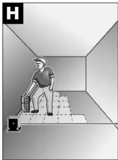
natural_image
Illustration of a person standing inside a room with a camera and floor grid, no text or symbols present
natural_image
Interior view of a room with a desk, chair, and ceiling-mounted device (no text or symbols visible)
natural_image
Interior hallway with window, door, and tiled floor (no text or symbols)
natural_image
3D architectural diagram showing a wall with brickwork and a mechanical component, no text or symbols presentGerätekennwerte
Baulaser BL 40 VHR
PROFESSIONAL
natural_image
Pure geometric diagram with crosshair and circular pattern (no text or symbols)Arbeitshinweise

natural_image
Mechanical component diagram showing a housing and its internal structure (no text or symbols)① Service: +43 (0)1/61 03 80
Fax +43 (0)1/61 03 84 91
© Kundenberater:....+43 (0)1/7 97 22 30 66
E-Mail: abe@abe-service.co.at
Schweiz
① 044/847 15 11
Fax 044/847 15 51
Luxemburg
① +32 (0)70/22 55 65
Fax +32 (0)70/22 55 75
E-Mail: Outillage.Gereedschap@be.bosch.com
1 609 929 E39 • (06.02) T
Deutsch-8


Senior Vice President
Engineering
Dr. Eckerhard Strötgen
Head of Product
Certification

i.v. Mige
Robert Bosch GmbH, Power Tools Division
Product Specifications
Construction Laser BL 40 VHR
PROFESSIONAL
Article number 0 601 096 703
Laser type 635 nm, <1 mW
Laser class 2
Working range 1)
Without receiver
With receiver
To approx. 50 m
To approx. 100 m
Levelling accuracy 1) 2)
<±0.3 mm/m
Rotational speed 3 Steps (70–680 RPM)
Laser beam diameter
at the unit 1) Approx. 5 mm
Batteries 2 x 1.5 V LR20 (D)
Operating time approx. 40 h
Tripod connection 1/4" horizontal and vertical
5/8" horizontal and vertical with adapter
Dimensions 150 mm x 120 mm x 140 mm
Weight in accordance with
EPTA-Procedure 01/2003 1 kg
Protection type IP 54
(dust and splash water protected)
Operating temperature -5 ... +45 °C
Storage temperature -20 ... +70 °C
1) at 25 °C
2) along the axis
Please refer to the article number on the nameplate of your unit since the trade designation of individual units can vary.
The serial number 15 of your unit for positive identification is located on the nameplate on the rear of the housing.
Noise Information
Measured values determined according to EN 60745.
Typically, the A-weighted sound pressure level of the product is less than 70 dB(A).
Intended Use
The unit is intended for projecting and checking precise horizontal planes, vertical lines, alignment lines and plumb points.
1 609 929 E39 • (06.02) T
English-1




Product Elements
Please open the foldout page with the illustration of the unit and leave it open while you read these operating instructions.
The numbering of the product elements refers to the illustration of the unit on the graphic page.
1 Prism cap
2 Plumb beam
3 Ring for line function
4 Mode selector switch
5 On-off switch
6 Bubble level (1)
7 Bubble level (2)
8 Adjustment knob (1)
9 Plumb notch
10 Adjustment knob (2)
11 Handle/rail for vertical positioning
12 Bubble level (3)
13 Battery compartment cover
14 Screw for battery compartment cover
15 Serial number
16 Tripod receptacle 1/4" (2x)
17 High performance receiver with universal holder*
18 BLM 260 construction laser measuring rod*
19 Ceiling measuring plate*
20 Measuring plate with base bracket*
21 Laser viewing glasses*
22 BS 200/BS 280 tripod*
23 5/8" Tripod adapter
24 Wall mount
25 Protective bag
* Not all the accessories illustrated or described are included in standard delivery.

For Your Safety
All instructions must be read completely and strictly followed to ensure safe and secure working with the measuring instrument. Do not make the warning signs on the measuring instrument unreadable. SAVE THESE INSTRUCTIONS IN A SECURE PLACE.


Do not point the laser beam at persons or animals and do not look into the laser bean, even from longer distances. This measuring instrument produces laser radiation of the laser class 2 according to EN 60825-1:1997. You can therefore unintentionally blind other persons with it.
1 609 929 E39 • (06.02) T
English-2





- Do not use the laser viewing glasses as protective glasses. The laser viewing glasses serve for better recognition of the laser beam, however, they do not protect against the laser radiation.
■Do not use the laser viewing glasses as sun glasses or in street traffic. The laser viewing glasses do not provide complete UV protection and reduce colour perception.
■Have the measuring instrument repaired only by qualified specialist personnel and only with original replacement parts. In this manner, it is ensured that the safety of the instrument is maintained.
■Do not allow children to use the laser measuring instrument without supervision. They could unintentionally blind other persons.
Protection of the Unit
■Avoid heavy shocks or falls. After heavy exterior influences on the unit, always perform a precision check before continuing work (see Section Levelling Accuracy).
■Do not immerse the unit in water.
■Do not expose the unit to extreme temperatures and temperature variations (e.g., do not leave in vehicles).
■If the unit is not used for a long period, the batteries must be removed (danger of self-discharge and corrosion).
E Inserting/Replacing the Batteries
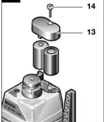
Loosen the screw of the battery compartment cover 14. Remove the battery compartment cover 13. Insert the batteries into the housing such that the negative terminals rest against the battery springs. Mount the cover and tighten the screw.
The 1.5 V mono-cells (LR 20) provided make possible an operating time of approx. 40 hours in rotation mode.
Extreme temperatures and the use of batteries of different charged conditions decrease the operational duration of the unit.
Always replace the complete set of battery. Use only batteries of a single manufacturer with the same capacity.
Putting into Operation
■Do not point the laser beam at persons or animals and do not look into the laser bean, even from longer distances. When the construction laser is switched on, the laser is activated. The laser emits beams upwards and to the side.
Switching On/Off: Press the on-off switch 5.
When the maximum allowed operating temperature of 45\ ircC is exceeded, the laser beam automatically switches off in order to protect the laser diode. After cooling, the unit is again ready for operation and can be switched on again.
1 609 929 E39 • (06.02) T
English-3
Levelling and Alignment of the Construction Laser
A Horizontal Alignment/Aligning the Plumb Beam
Switch on the construction laser and align with the bubble level (1) 6 by turning the adjustment knob (1) 8 to the right until level. The bubble level (3) 12 is aligned by turning the adjustment knob (2) 10 to the right. When the bubble levels 6 and 12 are aligned, the unit is level and ready for operation.
B Vertical Alignment
Switch on the construction laser and, as shown in the illustration, align the bubble level (2) 7 by rotating the adjustment knob (2) 10 up or down until level.
Note: When working over an extended period of time, check the position of the level bubbles regularly.
Levelling Accuracy
Influences on the Accuracy
The largest influence is exerted by the ambient temperature. Especially temperature differences occurring from the ground upwards can deflect the laser beam.
The deviations are significant at a distance of approx. 20 m and can double or quadruple at a distance of 100 m.
Since the temperature gradient near the floor is the greatest, a tripod should always be used when working at distances over 20 m. In addition, the unit should always be set up in the middle of the working area.
Accuracy Check of the Unit
In addition to external influences, deviations can also be caused by influences within the unit itself. For this reason, the accuracy should be checked from time to time.
Procedure
– A free measuring path of 20 m is required.
- A transit measurement on firm ground must be performed over both X and Y axes (four measurements).
- Place the unit in the horizontal position on a solid, level base and switch on.
- After levelling, mark the laser point (centre of the point) at a convenient position, for example, on a wall.
- Then rotate the unit by approx. 90irc without lifting it, i.e., without changing its height.
- Now turn back the prism cap 1, realign with the bubble levels and mark again. Repeat this procedure in two additional 90irc steps. The heights of all four measurements are now marked at the same position on the wall.


1 609 929 E39 • (06.02) T
English-4



The maximum deviation at 20 m must not exceed ±6 mm. Consequently, the highest and lowest markings can be 12 mm apart. This deviation results from tolerances of the unit and application when checking the accuracy. Should the unit be outside of these tolerances, please contact a Bosch Service Centre.

Operation
C Rotation operation
To select rotation operation, slide down the ring for the line function 3 and press the mode selector switch 4. The laser starts with the highest rotational speed. The rotational speed is adjustable in order to enhance the visibility of the laser beam. Repeated pressing of the mode selector switch 4 reduces the speed in 3 steps to a standstill.
When working with the receiver 17, the highest rotational speed is recommended.
When working without the receiver 17, the lowest rotational speed or line operation is recommended.
Point operation
After switching on, the unit emits a laser beam which is split into two beams at a right-angle at the laser exit.
In the horizontal position, this results in a continuous vertical plumb beam and a variable horizontal beam which is deflected by 90°.
In the vertical position, a continuous plane beam and a variable vertical beam are available.
By simply turning the prism cap 1, the variable beam is directed manually to the desired position.
Point operation is particularly well suited for interior work.
D Standard Line
To select line operation, slide up the ring for line function 3 and press the mode selector switch 4. The laser starts with the longest line length which is adjustable depending on the visibility and working area. Repeated pressing of the mode selector switch 4 reduces the length L of the line in 3 steps to a standstill.
By simply turning the prism cap 1, the line can be moved manually.
Set the desired line length before measuring.
Working Instructions

Do not point the laser beam at persons or animals and do not look into the laser bean, even from longer distances.
Working with a Tripod (Accessory)
The construction laser is equipped with 1/4" tripod receptacles 16 for horizontal and vertical applications. To mount the construction laser on a tripod 22 with 5/8" threads, use the adapter 23 provided.
For tripods 22 with a millimetre scale on the extension, the height offset can be set directly.

natural_image
Mechanical component assembly showing a housing and mounting bracket (no text or symbols visible)F Operation with Wall Mount
For work exceeding the extension height of tripods, the unit can be operated with the wall mount 24. Attach the wall mount 24 to the wall.
The construction laser is inserted into the wall mount from above and secured with the locking lever.
Measuring Rod (accessory)
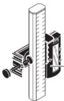
For outdoor work such as for checking surface evenness or marking inclines, it is recommended to use the measuring rod 18 together with the receiver 17.
On the measuring rod 18 (accessory), a relative millimetre scale ( ±50 cm) is applied at the top.
Its zero height (90–210 cm) can be selected on the extension. In this manner, deviations from the reference height can be read off directly.
Laser Viewing Glasses
The laser viewing glasses filter out the ambient light. As a result, the red light of the laser appears brighter to the eye.

Do not use the laser viewing glasses as protective glasses. The laser viewing glasses serve for better recognition of the laser beam, however, they do not protect against the laser radiation.
Do not use the laser viewing glasses as sun glasses or in street traffic. The laser viewing glasses do not provide complete UV protection and reduce colour perception.
Working Examples
G Projecting Horizontal Heights/Points
Place the construction laser on a sturdy support or use the tripod 22. Align the laser beam to the desired height. Determine the height difference between the laser beam and the height line at the reference point using the measuring rod (accessory).
Set the desired operating mode and project the height line.
1 609 929 E39 • (06.02) T
English-6


H Marking Right Angles
If right angles are to be marked, the laser beam must be aligned parallel to the reference line (tile edge, wall). The right angle is indicated by the deflected variable laser beam.
Projecting a Floor Point to the Ceiling (Plumb)
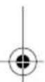
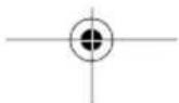
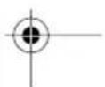
For exact alignment of the plumb beam (laser) over the floor point, plumb notches are located at the lower edge of the housing. For this purpose, mark two right-angle lines (crosshairs) through the floor point and align the unit with the plumb notches.
J Marking Plumb Lines
Set up the construction laser in the vertical position, e.g., in front of a wall and align the laser point/laser line onto the location where the plumb line is to be projected/marked. Select line or rotation operation and project/mark the plumb line.
K Indicating Vertical Planes (Partitions, Joint Cuts)
Set up the construction laser in the vertical position such that the laser point projects exactly onto the reference line, e.g., the partition. Then align the laser beam parallel to the reference wall. Select point or rotation operation and mark the beam points.
Marking Inclines
The unit can be set up in any inclined position. In this manner, the projection of all desired inclination angles is possible.
Maintenance and Cleaning
Clean the laser exit regularly using cotton swabs. Watch for fuzz residue.
■Always keep the unit clean.
Wipe off dirt with a damp, soft cloth. Do not use aggressive cleaning agents or solvents.
If the unit should fail despite the care taken in manufacture and testing, repair should be carried out by an authorised customer services agent for Bosch power-tools.
For all inquiries and replacement parts ordering, always include the 10-place article number on the nameplate of the unit.
Disposal
The measuring instrument, accessories and packaging should be disposed of for recycling in a environmental friendly manner.
Only for EU countries

Do not dispose of measuring instruments in the household waste!
According to the European Guidelines 2002/96/EG for waste electric and electronic equipment and its implementation into national law, measuring instruments that are no longer usable must be collected separately and recycled in an environmentally friendly manner.
1 609 929 E39 • (06.02) T
English-7





Batteries
Do not throw batteries into the household waste, fire or water. Batteries should be collected, recycled or disposed of in an environmentally friendly manner.
Only for EU countries
According to the Guidelines 91/157/EEC, defective or used batteries must be recycled.
Batteries/rechargeable batteries that are no longer useable can be sent directly to:
Great Britain
Robert Bosch Ltd. (B.S.C.)
P.O. Box 98
Broadwater Park
North Orbital Road
Denham-Uxbridge
Middlesex UB 9 5HJ
© Service +44 (0) 18 95/83 87 82
© Advice line ..... +44 (0) 18 95/83 87 91
Fax. +44 (0) 18 95/83 87 89
Service and Customer Advice
Exploded views and information on spare parts can be found under: www.bosch-pt.com.
Great Britain
Robert Bosch Ltd. (B.S.C.)
P.O. Box 98
Broadwater Park
North Orbital Road
Denham-Uxbridge
Middlesex UB 9 5HJ
© Service +44 (0) 18 95/83 87 82
Advice line +44 (0) 18 95/83 87 91
Fax. +44 (0) 18 95/83 87 89
Ireland
Beaver Distribution Ltd.
Greenhills Road
Tallaght-Dublin 24
© Service ....+ 353 (0)1/414 9400
Fax. + 353 (0)1/459 8030
Australia and New Zealand
Robert Bosch Australia Pty. Ltd.
RBAU/SBT
1555 Centre Road, P.O. Box 66
3168 Clayton/Victoria
①....+61(0)1/3 00 30 70 44
Fax. +61 (0)1/3 00 30 70 45
www.bosch.com.au


1 609 929 E39 • (06.02) T
English-8



Declaration of Conformity
CE
We declare under our sole responsibility that this product is in conformity with the provisions of the directive 98/37/EC.
Dr. Egbert Schneider
Dr. Eckerhard Strötgen
Senior Vice President
Head of Product
Engineering
Certification
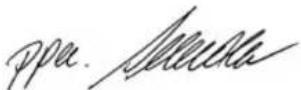
i.v. Mige
Robert Bosch GmbH, Power Tools Division
Specifications subject to change without notice


1 609 929 E39 • (06.02) T
English-9


B Alignment vertical
natural_image
Mechanical component diagram showing a housing and internal structure with no visible text or symbolsnatural_image
Pure geometric diagram with crosshair and circular pattern (no text or symbols)Robert Bosch France S.A.S.
Service Après-vente/Outillage
Senior Vice President
Engineering
Dr. Eckerhard Strötgen
Head of Product
Certification

i.v. Hirge
Robert Bosch GmbH, Power Tools Division
natural_image
Pure geometric diagram with crosshair and circular pattern (no text or symbols)natural_image
Mechanical component assembly showing a housing and mounting bracket (no visible text or symbols)Senior Vice President
Engineering
Dr. Eckerhard Strötgen
Head of Product
Certification

i.v. Mige
Robert Bosch GmbH, Power Tools Division
natural_image
Mechanical component assembly showing a housing and mounting bracket (no visible text or symbols)F Funcionamento com suporte de parede
natural_image
Pure geometric diagram with intersecting lines and a circular pattern (no text or symbols)J Marcar as verticais
① +351 21/8 50 00 00
Fax +351 21/8 51 10 96
Brasil
Robert Bosch Ltda.
Caixa postal 1195
13065-900 Campinas
0800/70 45446
E-Mail: sac@bosch-sac.com.br
Senior Vice President
Engineering
Dr. Eckerhard Strötgen
Head of Product
Certification

i.v. Mige
Robert Bosch GmbH, Power Tools Division
natural_image
Mechanical component assembly diagram showing a housing and mounting bracket (no text or symbols)natural_image
Pure geometric diagram with crosshair and circular pattern (no text or symbols)Esempi di lavoro
Senior Vice President
Head of Product
Engineering
Certification
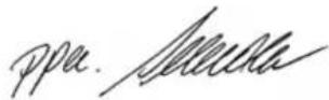
i.v. Mige
Robert Bosch GmbH, Power Tools Division
natural_image
Pure geometric diagram with crosshair and circular pattern (no text or symbols)Technische gegevens
Bouwlaser BL 40 VHR
PROFESSIONAL
natural_image
Mechanical component assembly showing a housing and internal parts (no visible text or symbols)Dr. Egbert Schneider Senior Vice President Engineering
Dr. Eckerhard Strötgen Head of Product Certification
ppa. Aucuta
i.v. Mige
Robert Bosch GmbH, Power Tools Division
natural_image
Mechanical component assembly showing a housing and mounting bracket (no text or symbols visible)Senior Vice President
Engineering
Dr. Eckerhard Strötgen
Head of Product
Certification
ppa. deuata
i.v. Mige
Robert Bosch GmbH, Power Tools Division
| Rotationshastighet 3 steg (70–680 min | -1) |
| ∅ Laserstråle på instrumentet1) ca. 5 mm |
natural_image
Mechanical component diagram showing a housing and mounting bracket assembly (no text or symbols)Senior Vice President
Engineering
Dr. Eckerhard Strötgen
Head of Product
Certification


Robert Bosch GmbH, Power Tools Division
23 Stativadapter 5/8"
24 Veggholder
natural_image
Mechanical component assembly diagram showing a housing and mounting bracket (no text or symbols)F Drift med veggholder
Senior Vice President
Engineering
Dr. Eckerhard Strötgen
Head of Product
Certification

i.v. Mige
Robert Bosch GmbH, Power Tools Division
Endringer forbeholdes
1 609 929 E39 • (06.02) T
Norsk-8


Tekniset tiedot
Rakennuslaser BL 40 VHR
PROFESSIONAL
natural_image
Mechanical component assembly showing a housing and mounting bracket (no visible text or symbols)Senior Vice President
Engineering
Dr. Eckerhard Strötgen
Head of Product
Certification
ppa. Aucu
i.v. Mige
Robert Bosch GmbH, Power Tools Division
natural_image
Mechanical component assembly showing a housing and mounting bracket (no visible text or symbols)Senior Vice President
Engineering
Dr. Eckerhard Strötgen
Head of Product
Certification

i.v. Mige
Robert Bosch GmbH, Power Tools Division
natural_image
Mechanical component diagram showing a housing and internal assembly (no text or symbols)natural_image
Pure geometric diagram with crosshair and circular pattern (no text or symbols)Çalışma örnekleri
Bosch San. ve Tic. A.S.
Ahi Evran Cad. No:1 Kat:22
Polaris Plaza
80670 Maslak/Istanbul
Senior Vice President
Engineering
Dr. Eckerhard Strötgen
Head of Product
Certification

i.v. Mige
Robert Bosch GmbH, Power Tools Division
natural_image
Mechanical component assembly showing a housing and internal components (no text or symbols visible)Senior Vice President
Engineering
Dr. Eckerhard Strötgen
Head of Product
Certification

i.v. Mige
Robert Bosch GmbH, Power Tools Division
natural_image
Mechanical component assembly showing a housing and internal components (no visible text or symbols)Senior Vice President
Head of Product
Engineering
Certification

i.v. Mige
Robert Bosch GmbH, Power Tools Division
Změny vyhrazeny
1 609 929 E39 • (06.02) T
Česky-8



Technické parametre
Stavebný laser BL 40 VHR
PROFESSIONAL
natural_image
Mechanical component assembly showing a housing and mounting bracket (no text or symbols visible)Senior Vice President
Engineering
Dr. Eckerhard Strötgen
Head of Product
Certification
ppa. devena
i.v. Mige
Robert Bosch GmbH, Power Tools Division
natural_image
Mechanical component assembly showing a housing and mounting bracket (no text or symbols visible)Senior Vice President
Engineering
Dr. Eckerhard Strötgen
Head of Product
Certification

i.v. Mige
Robert Bosch GmbH, Power Tools Division
natural_image
Mechanical component assembly showing a housing and mounting bracket (no text or symbols visible)Senior Vice President
Engineering
Dr. Eckerhard Strötgen
Head of Product
Certification
ppa. Aetena
i.v. Mige
Robert Bosch GmbH, Power Tools Division
natural_image
Mechanical component diagram showing a housing and internal structure with no visible text or symbolsSenior Vice President
Engineering
Dr. Eckerhard Strötgen
Head of Product
Certification

i.v. Mige
Robert Bosch GmbH, Power Tools Division
Можливі зміни
1 609 929 E39 • (06.02) T
Українська-8




natural_image
Mechanical component assembly showing a housing and mounting bracket (no text or symbols visible)Bosch Service Center
România
Str. Horia Măcelariu 30-34
sector 1, Bucureşti
① +40 (0)21/405 75 40
① +40 (0)21/405 75 41
① +40 (0)21/405 75 81
Fax +40 (0)21/405 75 66
Declaratie de conformitate
CE
Senior Vice President
Engineering
Dr. Eckerhard Strötgen
Head of Product
Certification

i.v. Mige
Robert Bosch GmbH, Power Tools Division
natural_image
Mechanical component assembly showing a housing and internal structure (no visible text or symbols)Senior Vice President
Engineering
Dr. Eckerhard Strötgen
Head of Product
Certification

i.v. Mige
Robert Bosch GmbH, Power Tools Division
natural_image
Mechanical component assembly showing a housing and internal structure (no visible text or symbols)F Rad sa zidnim držačem
Za radove, koji se nalaze iznad visine izvoda stativa, može aparat raditi sa zidnim držačem 24. Za montažu pričvrstite zidni držač 24 na zid.
Gradjevinski laser se ugura od gore u zidni držač i obezbedjuje sa polugom za blokadu.
Merna letva (pribor)
Za radove u prirodi, preporučuje se radi ispitivanja ravnoće odnosno nanosa i nagiba upotreba merne letve 18 zajedno sa prijemnikom 17.
Na mernoj letvi 18 (pribor) je gore naneta relativna milimetarska skala (±50 cm).
© Service +381 11-753-373
Fax +381 11-753-373
Senior Vice President
Engineering
Dr. Eckerhard Strötgen
Head of Product
Certification
i.v. Mige
Robert Bosch GmbH, Power Tools Division
natural_image
Mechanical component diagram showing a housing and internal structure with no visible text or symbolsSenior Vice President
Head of Product
Engineering
Certification

i.v. Mige
Robert Bosch GmbH, Power Tools Division
Pridržujemo si pravico do sprememb

1 609 929 E39 • (06.02) T
Slovensko-8



Tehnički podaci o uređaju
Gradevni laser BL 40 VHR
PROFESSIONAL
| Trgovačka oznaka 0 601 096 703 | |
| Tip lasera 635 nm, <1 mW | |
| Razred lasera 2 | |
| Radno područje 1) bez prijemnikas prijemnikom | do cca. 50 mdo cca. 100 m |
| Točnost niveliranj 1) 2) | <±0,3 mm/m |
| Brzina rotacije 3 stupnja (70–680 min | -1) |
| ∅ laserske zrake na uređaju 1) cca. 5 mm | |
| Baterije 2 x 1,5 V LR20 (D) | |
| Trajanje rada cca. 40 h | |
| Priključak na stativ 1/4" horizontalni i vertikalniPreko adaptera 5/8" horizontalni i vertikalni | |
| Mjere | 150 mm x 120 mm x 140 mm |
| Težina prema EPTA-Procedure 01/2003 1 kg | |
| Vrsta zaštite IP 54 (zaštićeno od prašine i prskanja vode) | |
| Radna temperatura -5 ... +45 °C | |
| Temperatura spremanja -20 ... +70 °C | |
natural_image
Mechanical component assembly showing a housing and internal structure (no visible text or symbols)F Rad sa zidnim držačem
Za radove koji leže iznad visine izvlačenja stativa, uređaj može raditi pomoću zidnog držača 24. Za montažu, zidni držač 24 pričvrstiti na zid.
Gradevni laser se odozgo uvuče u zidni držač i osigura polugom za aretiranje.
Mjerna letva (pribor)
Senior Vice President
Engineering
Dr. Eckerhard Strötgen
Head of Product
Certification

Robert Bosch GmbH, Power Tools Division
natural_image
Mechanical component assembly diagram showing a housing and internal structure (no text or symbols)F Seinakinnitusrakise kasutamine
Senior Vice President
Engineering
Dr. Eckerhard Strötgen
Head of Product
Certification
ppa. deuena
i.v. Mige
Robert Bosch GmbH, Power Tools Division
natural_image
Mechanical component assembly showing a housing and internal casing (no text or symbols visible)Senior Vice President
Engineering
Dr. Eckerhard Strötgen
Head of Product
Certification
i.v. Mige
Robert Bosch GmbH, Power Tools Division
23 Stovo adapteris 5/8"
natural_image
Mechanical component assembly showing a housing and mounting bracket (no text or symbols visible)F Darbas su sieniniu laikikliu
Senior Vice President
Engineering
Dr. Eckerhard Strötgen
Head of Product
Certification

i.v. Mige
Robert Bosch GmbH, Power Tools Division
Galimi pakeitimai
1 609 929 E39 • (06.02) T
Lietuviškai-8




BOSCH

natural_image
Black and white striped flag pattern with no text or symbolsRobert Bosch GmbH
Power Tools Division
70745 Leinfelden-Echterdingen
www.bosch-pt.com
1 609 929 E39 (06.02) T/230





- Gerätekennwerte
- Arbeitshinweise
- Schweiz
- Luxemburg
- Product Specifications
- Construction Laser BL 40 VHR
- PROFESSIONAL
- Noise Information
- Intended Use
- English-1
- Product Elements
- For Your Safety
- English-2
- Protection of the Unit
- E Inserting/Replacing the Batteries
- Putting into Operation
- Levelling and Alignment of the Construction Laser
- A Horizontal Alignment/Aligning the Plumb Beam
- B Vertical Alignment
- Levelling Accuracy
- Influences on the Accuracy
- Accuracy Check of the Unit
- Procedure
- Operation
- C Rotation operation
- Point operation
- D Standard Line
- Working Instructions
- Working with a Tripod (Accessory)
- F Operation with Wall Mount
- Measuring Rod (accessory)
- Laser Viewing Glasses
- Working Examples
- G Projecting Horizontal Heights/Points
- H Marking Right Angles
- Projecting a Floor Point to the Ceiling (Plumb)
- J Marking Plumb Lines
- K Indicating Vertical Planes (Partitions, Joint Cuts)
- Marking Inclines
- Maintenance and Cleaning
- Disposal
- Only for EU countries
- Batteries
- Great Britain
- Service and Customer Advice
- Ireland
- Australia and New Zealand
- Declaration of Conformity
- B Alignment vertical
- F Funcionamento com suporte de parede
- J Marcar as verticais
- Brasil
- Esempi di lavoro
- Technische gegevens
- F Drift med veggholder
- Tekniset tiedot
- Çalışma örnekleri
- Technické parametre
- Можливі зміни
- Declaratie de conformitate
- CE
- F Rad sa zidnim držačem
- Merna letva (pribor)
- Tehnički podaci o uređaju
- Mjerna letva (pribor)
- F Seinakinnitusrakise kasutamine
- F Darbas su sieniniu laikikliu
- Galimi pakeitimai
- BOSCH
Brand : BOSCH
Model : BL 40 VHR Professional
Category : Rangefinder