82SN61 - Snow blower Cramer - Free user manual and instructions
Find the device manual for free 82SN61 Cramer in PDF.

User questions about 82SN61 Cramer
0 question about this device. Answer the ones you know or ask your own.
Ask a new question about this device
Download the instructions for your Snow blower in PDF format for free! Find your manual 82SN61 - Cramer and take your electronic device back in hand. On this page are published all the documents necessary for the use of your device. 82SN61 by Cramer.
USER MANUAL 82SN61 Cramer
HE | LT | LV | ET | MK | SR
natural_image
Line drawing of a snowman blade with open bushing and wheels (no text or symbols)DECLARATION OF CONFORMITY (UK)
Name and address of the manufacturer:
Name: Globe Technologies Europe GmbH
Address: Brunnenweg 17, 64331 Weiterstadt, Germany
Name and address of the Authorized representative:
Name: Garden Equipment Ltd
Address: First Floor, 3a Groveley Road, Christchurch, Dorset, BH23 3HB, UK
Name and address of the person authorised to compile the technical file:
Name: Simon Del-Nevo
Address: First Floor, 3a Groveley Road, Christchurch, Dorset, BH23 3HB, UK
Here with we declare that the product
Category: Snow Thrower
Model: SNB408 (82SN61)
Serial number: See product rating label
Year of Construction: See product rating label
- is in conformity with the relevant provisions of the Supply of Machinery (Safety) Regulations 2008.
- is in conformity with the provisions of the following other UK legislation:
• Electromagnetic Compatibility Regulations 2016 - Noise Emission in the Environment by Equipment for use Outdoors Regulations 2001
• The Restriction of the Use of Certain Hazardous
• substances in Electrical and Electronic Equipment Regulations 2012
Furthermore, we declare that the following standard have been used:
BS EN 62841-1, ISO/DIS 8437, BS EN 62233, BS EN 55014-1, BS EN 55014-2,
BS EN ISO 3744, ISO 11094, BS EN 62321-3-1, BS EN 62321-4, BS EN 62321-5,
BS EN 62321-6, BS EN 62321-7-1, BS EN 62321-7-2, BS EN 62321-8
Conformity assessment method to SCHEDULE 9 Noise Emission in the Environment by Equipment for use Outdoors Regulations 2001.
Notified body involved:
Name: Intertek Testing & Certification Ltd
Address: 9 Brook St, Brentwood CM14 5NQ United Kingdom
Measured sound power level 87.5 dB(A)
Guaranteed sound power level 114 dB(A)
Place, date: Christchurch, Dorset, UK 06.06.2023 Signature: Ted Qu, Quality Director
English
EN
1 Description......4
1.1 Purpose......4
1.2 Overview.... 4
2 Safety......4
3 Installation.... 4
3.1 Unpack the machine......4
3.2 Install the upper handle....4
3.3 Install the discharge chute....5
3.4 Install the chute control rod.... 5
3.5 Install the battery pack.... 5
3.6 Remove the battery pack.... 5
4 Operation.... 5
4.1 Cold weather operation.... 5
4.2 Use of control panel.... 5
4.3 Start and stop the auger/impeller...... 6
4.4 Adjust the auger speed.... 6
4.5 Self-propelled drive mode.... 6
4.6 Start auger and self-propelled drive simultaneously ....7
4.7 Lock self-propelled drive paddle and auger engagement paddle with one hand....7
4.8 Manually move the machine....7
4.9 LED headlights....7
4.10 Adjust the discharge chute....7
4.11 Adjust the chute deflector....7
4.12 Operation tips....8
5 Maintenance....8
5.1 General maintenance......8
5.2 Clear the clogged chute.... 8
5.3 Replace the skid shoes.... 8
5.4 Replace the scraper plate.... 8
5.5 Replace the safety pin....9
5.6 Replace the drift cutter.... 9
5.7 Store the machine....9
6 Troubleshooting...... 9
7 Technical data......10
8 EC Declaration of conformity...10
1 DESCRIPTION
1.1 PURPOSE
This product has been designed and built to remove and clear away snow from pavements, drives and other ground-level surfaces.
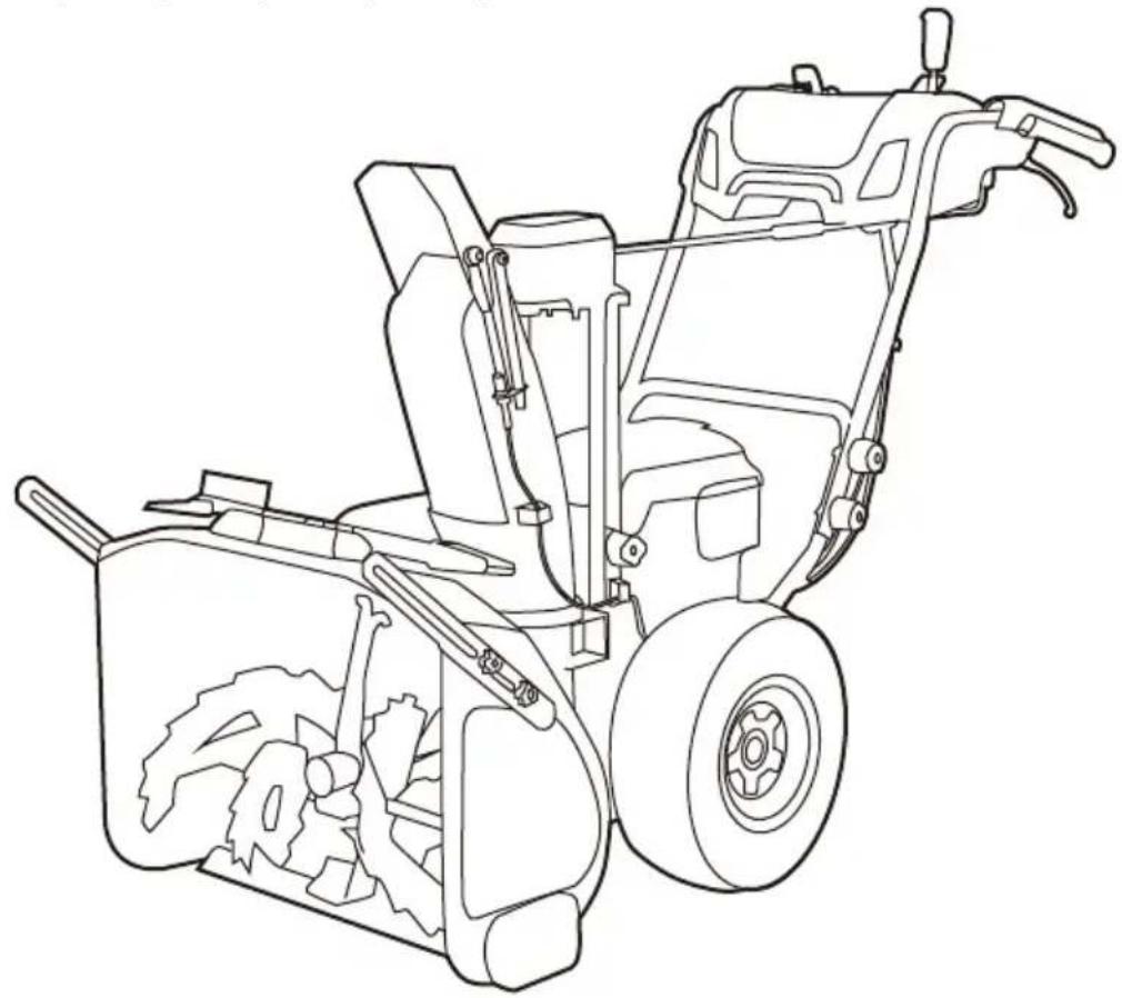
1.2 OVERVIEW
Figure 1 - 23
| 1 | Self-propelled drive paddle |
| 2 | Chute deflector adjustment handle |
| 3 | Auger engagement paddle |
| 4 | LED-headlight adjustment button |
| 5 | Drive speed control switch |
| 6 | ON button |
| 7 | Auger speed control switch |
| 8 | LED-headlight |
| 9 | Discharge chute adjustment handle |
| 10 | Upper handle |
| 11 | Lower handle |
| 12 | Battery compartment |
| 13 | Chute deflector |
| 14 | Discharge chute |
| 15 | 3-in-1 Cleanout Tool |
| 16 | Drift cutter |
| 17 | Intake housing |
| 18 | Auger |
| 19 | Scraper plate |
| 20 | Skid shoe |
| 21 | Wheel |
| 22 | Left zero turn trigger |
| 23 | Right zero turn trigger |
| 24 | Handle bolt |
| 25 | Handle knob |
| 26 | Bolt |
| 27 | Knob |
| 28 | Clip |
| 29 | Slot |
| 30 | Bracket |
| 31 | Bolt |
| 32 | Chute support |
| 33 | Cable |
| 34 | Discharge chute bolt |
| 35 | Pin |
| 36 | Battery release button |
| 37 | Screw |
| 38 | Chassis plate |
| 39 | Bolt |
40 Spacer
41 Nut
42 Scraper plate screw
43 Scraper plate spacer
44 Scraper plate nut
45 Auger safety pin
46 Spare auger safety pins
47 Drift cutter screw
48 Drift cutter knob
2 SAFETY
WARNING
Make sure that you follow all safety instructions.
Refer to Safety Manual.
3 INSTALLATION
WARNING
Do not use accessories that are not recommended by the manufacturer.
WARNING
Do not put in the battery packs until you finalized the assembly of all the parts.
3.1 UNPACK THE MACHINE
WARNING
Make sure that you correctly assemble the machine before use.
WARNING
- If the parts are damaged, do not use the machine.
- If you do not have all the parts, do not operate the machine.
-
If the parts are damaged or missing, speak to the service center.
-
Open the package.
- Read the documentation in the box.
- Remove all the unassembled parts from the box.
- Remove the machine from the box.
- Discard the box and package in compliance with local regulations.
3.2 INSTALL THE UPPER HANDLE
Figure 3 - 4
| 1. Align the holes in the middle handle and the upper handle. |
- Insert the bolt through the middle handle and upper handle.
- Tighten the handle knob onto the bolt.
- Repeat for left/right side.
3.3 INSTALL THE DISCHARGE CHUTE
Figure 5 - 6
- Loosen the knob and bolt on the discharge chute assembly.
- Align the holes on the discharge chute with the holes on the lower support.
- Once you have engaged the discharge chute onto the chute base, push until you hear a click.
- Insert the bolt through the holes and tighten with the knob.
- Fix the wire by rolling up the clip.
3.4 INSTALL THE CHUTE CONTROL ROD
Figure 7 - 8
- Make sure that the discharge chute faces forward.
- Keep the grip handle up.
- Push the chute control rod through the slot below the control panel.
- Put the end of the chute control rod straight through the hole of the chute support.
- Align the holes on the bracket with the holes below the control panel. Tighten with the bolts.
i NOTE
Make sure that the bracket is in the middle of the spacers.
-
Pull the cable to attach onto bottom of the rod. Align the holes, insert the bolt through the holes and lock with the pin.
-
Pull the grip handle back and then turn the grip handle left and right to make sure that the discharge chute moves in the desired direction.
3.5 INSTALL THE BATTERY PACK
WARNING
- If the battery pack or charger is damaged, replace the battery pack or the charger.
- Stop the machine and wait until the engine stops before you install or remove the battery pack.
- Read, know, and do the instructions in the battery and charger manual.
i NOTE
Install two batteries for operation or three for extended runtime.
Figure 9
- Open the battery lid.
- Align the lift ribs on the battery pack with the grooves in the battery compartment.
- Push the battery pack into the battery compartment until the battery pack locks into place.
- When you hear a click, the battery pack is installed.
- Close the battery door.
3.6 REMOVE THE BATTERY PACK
- Open the battery lid.
- Push and hold the battery release button.
- Remove the battery pack from the machine.
4 OPERATION
WARNING
Wear eye protection during operation.
The safe battery operation temperature ranges from 1^ F ( -17^ C) to 113^ F ( 45^ C).
WARNING
Do not store or charge battery outside.
Battery must be charged and stored indoors prior to use of the machine.
If the machine does not start:
- remove the battery pack from the machine,
- charge the battery pack to 15 minutes in warm area, or when the charging light turns green.
• Install the battery pack back in the unit.
4.2 USE OF CONTROL PANEL
Figure 2, 12
| No. | Name Function | |
| 1 | Self-propelled drive paddle | This machine allows self propelled drive mode that it can walk itself. Self propelled drive mode brings you easy operation. |
| 22 | Zero turn trigger | Turn assist handles for quick and effortless steering. This machine is equipped with zero turn system, which gives the machine accurate and smooth steering without devia-tion. |
| 23 | ||
| 2 | Chute deflector control handle | The chute deflector can be adjusted up and down to adjust the throwing distance of snow. |
| 3 | Auger/impeller control trigger | The auger/impeller can be started to rotate when machine is moving. Roatating auger/impeller breaks snow easily and clears snow quickly. |
| 4 | LED headlight button | Push button (A, B, C, D) to adjust the rear/front headlights. |
| E | Battery indicator | Power display for each battery (3 pcs). |
| 5 | Self-propelled drive speed control switch | Allows operators to select a comfortable driving speed. It gives 3 forward speeds and 1 backward self-propel-led and 1 neutral. |
| 6 | ON but-ton | The ON button is used to turn the machine on. |
| 7 | Auger/impeller speed control switch | Adjust the switch to control the aug-er/impeller run fast or slowly. |
| 9 | Chute control rod | Control the 200° adjustable discharge chute to turn to multiple different di-rections. |
4.3 START AND STOP THE AUGER/IMPELLER
Figure 2
To start auger/impeller:
- Push the ON button.
- Depress and hold the auger paddle.
i NOTE
Finish these 2 actions within 5 seconds.
To stop auger/impeller:
- Release the auger paddle.
i NOTE
Lower the scraper to the ground to remove the snow.
WARNING
Keep bystanders a safe distance from the machine.
WARNING
Examine the work area. Remove all stones, sticks, wire, bones, and other debris that can ricochet because of the rotating impeller.
4.4 ADJUST THE AUGER SPEED
Figure 2
(If the unit is in the OFF position):
- Push the ON button.
- Depress and hold the auger paddle.
- To increase the auger speed, push the auger speed lever forward.
- To decrease the auger speed, pull the auger speed lever backwards.
i NOTE
Lower the scraper to the ground to remove the snow.
WARNING
Keep bystanders a safe distance from the machine.
WARNING
Examine the work area. Remove all stones, sticks, wire, bones, and other debris that can ricochet because of the rotating impeller.
4.5 SELF-PROPELLED DRIVE MODE
Figure 2
To start drive system:
- Push the ON button.
- Depress and hold the drive paddle.
- To increase the drive speed, push the drive speed control lever forwards.
- To decrease the drive speed, pull the drive speed control lever backwards.
To stop the drive system:
- Release the drive paddle.
i NOTE
If machine is left idle, in either operation for longer than 5 seconds, you will need to start the process over again.
To turn left:
- Depress and hold the drive paddle.
- Pull the left zero turn trigger to turn the machine to left.
To turn right:
- Depress and hold the drive paddle.
- Pull the right zero turn trigger to turn the machine to right.
i NOTE
For self-propelled drive mode, this machine provides with 3 forward speeds and 1 reverse.
4.6 START AUGER AND SELF-PROPELLED DRIVE SIMULTANEOUSLY
Figure 2
- Push the ON button.
- Depress and hold the auger engagement paddle to start the auger.
- Depress and hold the drive paddle to start self-propelled drive.
i NOTE
Finish these 3 actions within 5 seconds.
4.7 LOCK SELF-PROPELLED DRIVE PADDLE AND AUGER ENGAGEMENT PADDLE WITH ONE HAND
Figure 2
When you push the self-propelled drive paddle and the auger engagement paddle at the same time, the auger engagement paddle will be temporarily locked.
Release the auger engagement paddle (right hand) and the auger engagement paddle will remain engaged.
This feature allows you to adjust the auger speed, self-propelling speed, and discharging direction of the snow while the auger rotates.
To stop the auger, release the self-propelled drive paddle and both the auger and the self-propel function will stop.
4.8 MANUALLY MOVE THE MACHINE
Figure 10 - 11
i NOTE
When the pushing resistance of the whole machine becomes large or cannot be pushed, the user needs to check whether the unilateral wheel can be turned by hand when it is off the ground. If it can't be rotated easily, you need to disassemble the chassis bottom plate and unplug the motor cable. Manual promotion can be resumed at this time.
- Unscrew the eight screws.
- Remove the bottom chassis plate.
- Unplug the motor cable.
- Reinstall the bottom plate with eight screws.
- Manually push the machine to move.
4.9 LED HEADLIGHTS
Figure 2, 12
Turning the headlights on :
- Push the button to turn on the LED light.
- Push the button to turn off the LED light.
Turning the headlights off :
Push button to adjust the light:
• A. Turn on the front lights.
• B. Turn on the rear lights.
• C. Turn on all lights.
• D. Warning light.
4.10 ADJUST THE DISCHARGE CHUTE
Figure 13 - 15
You can adjust the discharge chute 200^ to change snow discharge chute direction.
- Pull back the chute adjustment handle for a short distance.
(The lock button will be pulled down to allow the chute move.) - Rotate the chute adjustment handle left to move the discharge chute to the left. Release the grip handle to lock the chute in the desired direction.
- Rotate the chute adjustment handle right to move the discharge chute to the right. Release the grip handle to lock the chute in the desired direction.
4.11 ADJUST THE CHUTE DEFLECTOR
Figure 2, 16
You can adjust the chute deflector up and down to change the throwing distance of the snow.
WARNING
Turn off the machine before you adjust the chute deflector.
WARNING
Do not push the trigger so far forward that a gap shows between the deflector and the chute.
- Grip and hold the chute deflector control lever.
- Pull the chute deflector control lever to the left and hold to unlock position.
- Move the chute deflector control lever forward to adjust the deflector down and decrease the snow throw distance.
- Move the chute deflector control lever backward to adjust the deflector up and increase the snow throw distance.
4.12 OPERATION TIPS
- If it is possible, clear the snow with the direction of the wind.
- In strong winds, lower the chute deflector to direct the snow to the ground.
- When you complete the work, let the machine operate for a while to prevent ice formation in the discharge chute.
- If the snow is deeper than 20~cm , decrease the speed and let the machine work at its own rhythm.
- Do not use the scraper to remove compact snow and ice.
5 MAINTENANCE
WARNING
Remove the safety key and battery pack from the machine before maintenance.
CAUTION
Use only approved replacement parts.
CAUTION
Do not let brake fluids, gasoline, petroleum-based materials touch the plastic parts. Chemicals can cause damage to the plastic, and make the plastic unserviceable.
CAUTION
Do not use strong solvents or detergents on the plastic housing or components.
5.1 GENERAL MAINTENANCE
- Before each use, examine the machine for damaged, missing, or loose parts such as screws, nuts, bolts and caps.
- Tighten all the fasteners and caps correctly.
- Clean the remaining snow on the machine with a brush.
5.2 CLEAR THE CLOGGED CHUTE
WARNING
- Never use your hand to clean out the chute. Failure to follow these instructions can result in serious personal injury.
- Never reach into the discharge chute or place any body part in front of the snow thrower when the unit is operating or when the battery packs are installed.
Figure 17
To clear the discharge chute:
- Loosen the handle to turn off the machine.
- Remove the battery backs.
- Wait 10 seconds to be sure the auger has stopped rotating.
- Always use the chute clean tool which is attached to the machine as an accessory.
5.3 REPLACE THE SKID SHOES
i NOTE
The range of adjustable height for skid shoes is 1.5mm, when putting the bolts through the U-hole on the skid shoes.
Figure 18
- Loosen the 2 sets of bolts, spacers and nuts that attach the skid shoe to the snow thrower housing.
- Remove the skid shoe.
- Install the new skid shoe.
- Repeat the same operation on the other side.
5.4 REPLACE THE SCRAPER PLATE
WARNING
Use only approved replacement scraper plates.
WARNING
Wear heavy gloves or wind cloth around the blade when you touch the blade.
Figure 19
- Remove the nuts and spacers from scraper plate.
- Remove the screws and discard the old scraper plate.
- Install the new scraper plate.
- Reinstall the screws, spacer plates and tighten them with the nuts.
5.5 REPLACE THE SAFETY PIN
Figure 20 - 21
i NOTE
The safety pin is used to disperse the pressure of snow to protect the auger/impeller bar.
- Remove the nuts and safety pins.
- Install the new safety pins. (The spare safety pins are on the top of the chute support.)
5.6 REPLACE THE DRIFT CUTTER
Figure 22 - 23
- Remove the batteries.
- Insert the two bolts into the intake housing wall.
- Install the drift cutter and wing nuts onto the bolts.
- Pre-tighten the wing nuts and keep the drift cutter a little loose for adjustment.
- Move the drift cutter to the desired position and tighten the wing nuts.
5.7 STORE THE MACHINE
- Clean the machine before storage.
- Make sure the motor is not hot when you store the machine.
- Make sure that the machine does not have loose or damaged parts. If it is necessary, do these steps/instructions:
- Replace the damaged parts.
- Tighten the bolts.
- Speak to a person at an approved service center.
- Store the machine in a dry area.
- Make sure that children cannot come near the machine.
6 TROUBLESHOOTING
| Problem Possible cause | Solution | |
| The handle is not in position. | The bolts are not engaged correctly. | Adjust the height of the handle and make sure that the knobs and bolts are aligned correctly. |
| The machine does not start. | The battery is not charged. | Charge the battery by following the procedures in the battery and charger manual. |
| The switch is defective. | Have the switch replaced by an authorized service center. |
| Problem Possible cause | Solution |
| Battery is too cold. Remove battery from snow thrower. Place battery on charger and allow to charge for 10 minutes or until the changing light turns green. Remove from charger and install in snow thrower for use. | |
| Blue LED light is Flashing - Battery is in Low Voltage Protection. Bring the Battery and Charger in to a warm area. Place the Battery in the charger and allow for the battery to reach room temperature or when the light on the charger is flashing Green. Once charger is flashing green, take the battery and place it in the unit to begin work. | |
| Blue LED light is always on - Battery Temperature is Low. Bring the Battery and Charger in to a warm area. Place the Battery in the charger and allow for the battery to reach room temperature or when the light on the charger is flashing Green. Once charger is flashing green, take the battery and place it in the unit to begin work. | |
| Battery may require service or replacement. Call toll free helpline, at or replace battery. | |
| The engine is on, but the impeller does not turn. | The belt is damaged. Replace the belt. |
| A thin layer of snow stays behind. | The scraper is damaged. Replace the scraper. |
* If you cannot find the solution to these problems, call.
7 TECHNICAL DATA
| Voltage 82V | |
| Clearing width 61.0 cm | |
| Intake height 46 cm | |
| Throwing distance 15 m | |
| Wheel size 38.1 cm | |
| Weight (without battery and charger) | 80 kg (176.4 lbs) |
| Battery 82V180/ 82V290P/ | 82V360/ 82V580P and other BAB series |
| Charger 82C1G/ 82C2/ 82C | 6 and other CAB series |
| Measured sound pressure level | 80 dB(A), K_pA = 3 dB(A) |
| Guaranteed sound power level | 91 dB(A) |
| Vibration < 2.5 m/s | ^2 , K = 1.5 m/s ^2 |
8 EC DECLARATION OF CONFORMITY
Name and address of the manufacturer:
Name: Globe Technologies Europe GmbH
Address: Brunnenweg 17, 64331 Weiterstadt, Germany
Name and address of the person authorised to compile the technical file:
Name: Ralf Pankalla
Address: Brunnenweg 17, 64331 Weiterstadt, Germany
Herewith we declare that the product
Category: Snow Thrower
Model: SNB408(82SN61)
Serial number: See product rating label
Year of Construction: See product rating label
• is in conformity with the relevant provisions of the Machinery Directive 2006/42/EC.
- is in conformity with the provisions of the following other EC-Directives:
• 2014/30/EU
• 2000/14/EC & 2005/88/EC
• 2011/65/EU & (EU)2015/863
Furthermore, we declare that the following parts, clauses of harmonised standards have been used:
- EN 62841-1, ISO/DIS 8437, EN 62233, EN ISO 3744, EN 55014-1, EN 55014-2, ISO 11094, IEC 62321-3-1, IEC 62321-4, IEC 62321-5, IEC 62321-6, IEC 62321-7-1, IEC 62321-7-2. IEC 62321-8
Conformity assessment method to Annex VI Directive 2000/14/EC.
Measured sound power level L WA: 87.5 dB(A)
Guaranteed sound power level L_WA.d : 91 dB(A)
Notified body involved:
Address: Stangenstr. 1, 70771 Leinfelden-Echterdingen, Germany
Place, date: Malmö, Signature: Ted Qu, Quality Director 25.05.2023
Ted Qu
Deutsch
3.2 OBEREN GRIFF MONTIEREN
Abbildung 3 - 4
Deutsch
8 DÉCLARATION DE CONFORMITÉ CE
5.4 VERVANG DE SCHRAAPPLAAT.
WAARSCHUWING
4.8 FLYTT MASKINEN MANUELT
Figur 10 - 11
i MERK
5.1 GENERELT VEDLIKEHOLD
5.4 BYTT UT SKRAPEPLATEN
ADVARSEL
Varslet organ involvert:
Navn: Intertek Deutschland GmbH (varslede myndigheter 0905)
Adresse: Stangenstr. 1, 70771 Leinfelden-Echterdingen, Tyskland
Sted, dato: Malmö, 25.05.2023
Signatur: Ted Qu, Kvalitetsdirektør
Ted Qu
Dansk
1 Beskrivelse...... 89
5.5 SÆT SIKKERHEDSSTIFTEN I IGEN
Figur 20 - 21
i BEMAERK
4.8 STROJ PŘESUŇTE MANUÁLNĚ
Obrázek 10 - 11
i POZNÁMKA
.הכלההוּרָהוּרָהוּרָהוּרָהוּרָהוּרָהוּרָהוּרָהוּרָהוּרָהוּרָהוּרָהוּרָהוּרָהוּרָה:4
.הכלההוּרָהוּרָהוּרָהוּרָהוּרָהוּרָהוּרָהוּרָהוּרָהוּרָהוּרָהוּרָהוּרָהוּרָהוּרָה
.הכלההוּרָהוּרָהוּרָהוּרָהוּרָהוּרָהוּרָהוּרָהוּרָהוּרָהוּרָהוּרָהוּרָהוּרָהוּרָה:5
הכלהה 3.6
.הכלההוּרָהוּרָהוּרָהוּרָהוּרָהוּרָהוּרָהוּרָהוּרָהוּרָהוּרָהוּרָהוּרָהוּרָהוּרָה
תְּלָהִי i
.הכלההוּרָהוּרָהוּרָהוּרָהוּרָהוּרָהוּרָהוּרָהוּרָהוּרָהוּרָהוּרָהוּרָהוּרָהוּרָה
הכלה 4.9
12, 21'X
.הכלההוּרָהוּרָהוּרָהוּרָהוּרָהוּרָהוּרָהוּרָהוּרָהוּרָהוּרָהוּרָהוּרָהוּרָהוּרָה:2
7
.Annex VI Directive 2000/14/EC-7
WA: 87,5 dB(A)
תְרָה בַרִי אַעֹאָה
WA.d: 91 dB(A)
7 TECHNINIAI DUOMENYS
6 PROBLÉMU NOVĚRŠANA