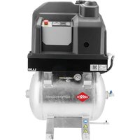
APS 3 Combi Compact - Compressor Airpress - Free user manual and instructions
Find the device manual for free APS 3 Combi Compact Airpress in PDF.


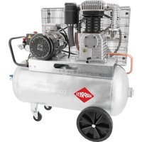
| Product Type | Screw compressor with 90 L air tank |
| Model | APS 3 Combi Compact |
| Brand | Airpress |
| Maximum operating pressure | 10 bar (adjustable from 0.5 to 16 bar) |
| Air flow at 8 bar | 292 L/min (according to ISO 1217) |
| Air flow at 10 bar | 261 L/min (according to ISO 1217) |
| Tank capacity | 90 L |
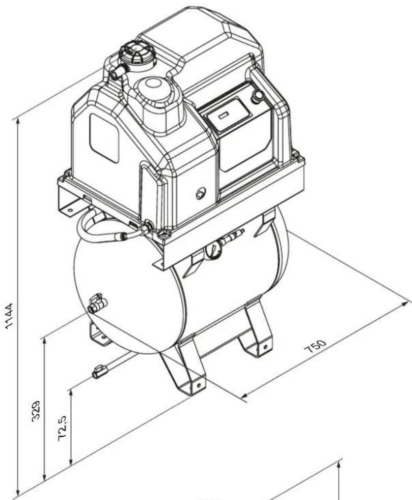
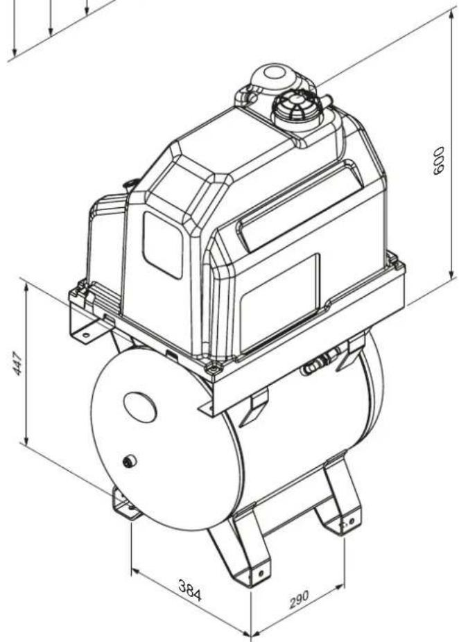
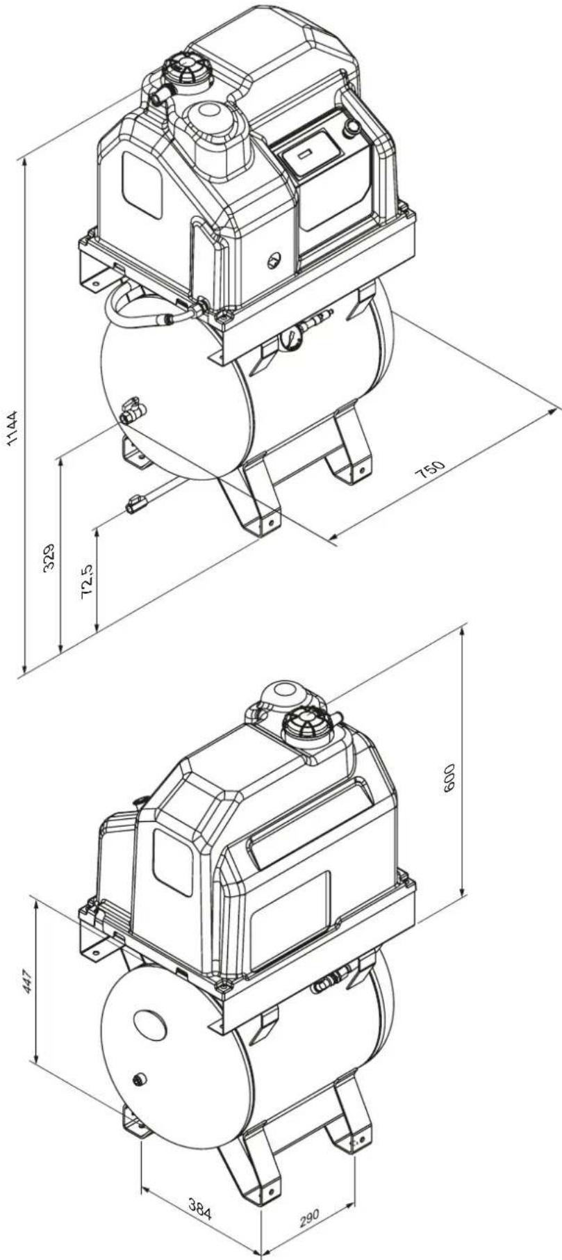
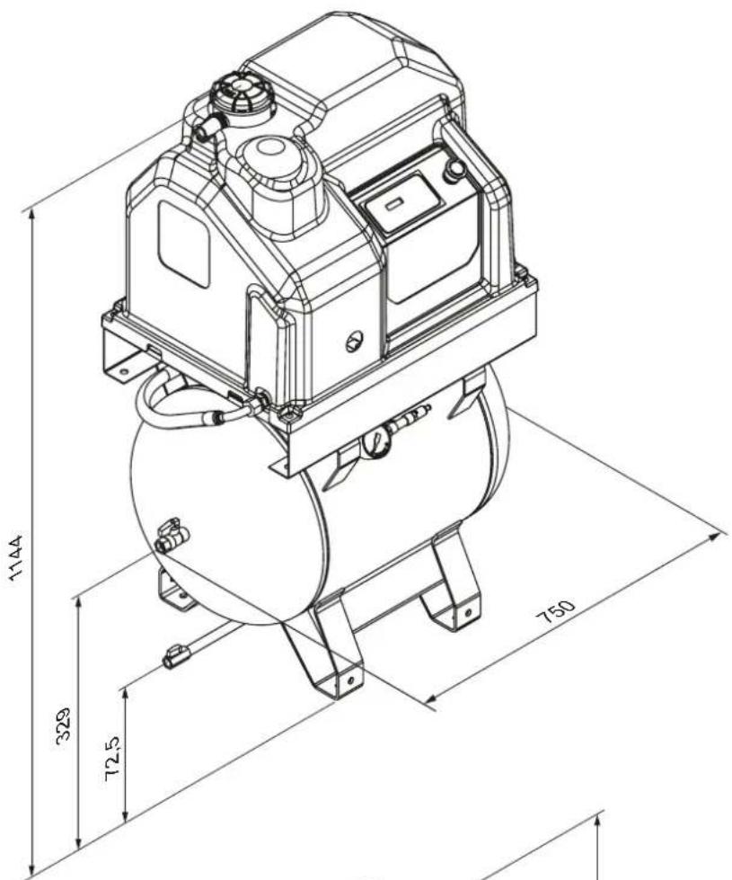
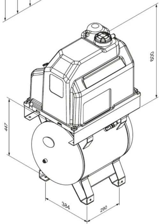
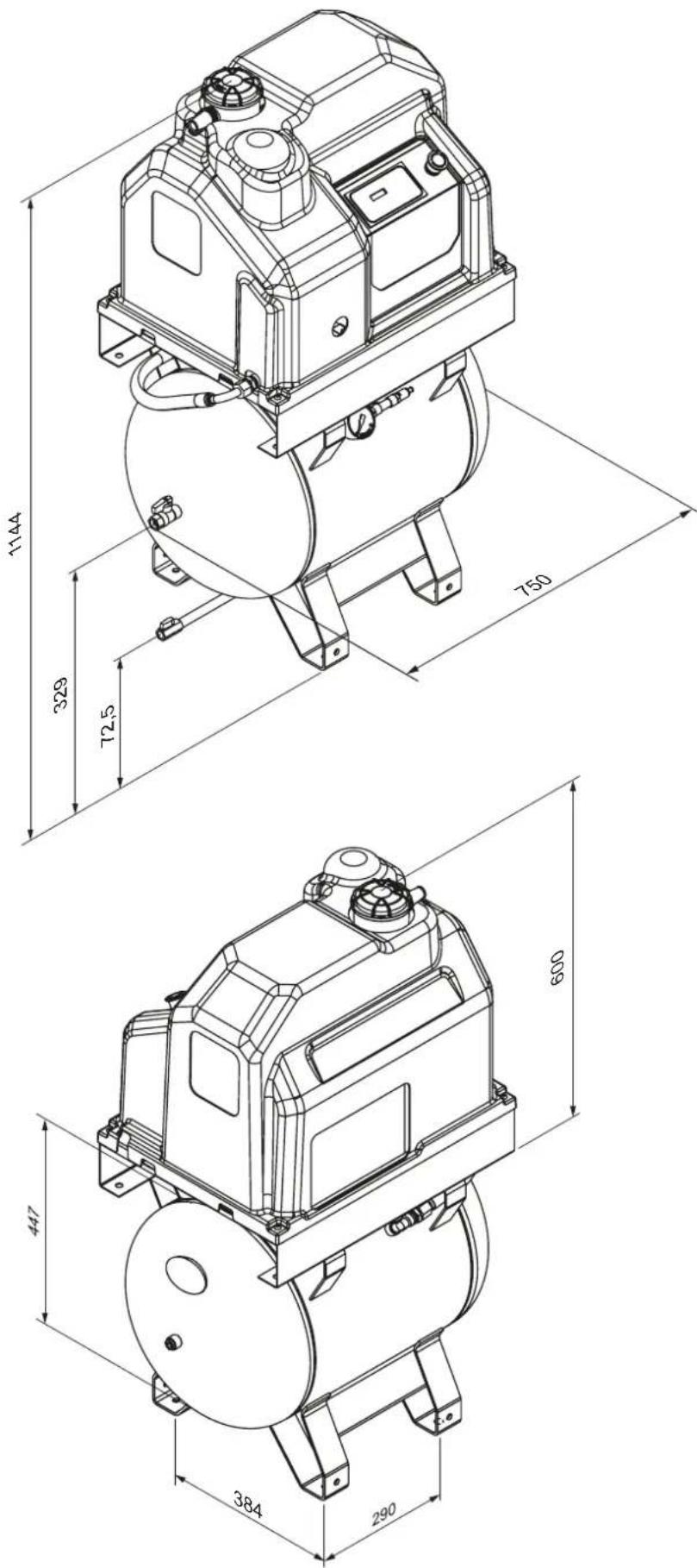
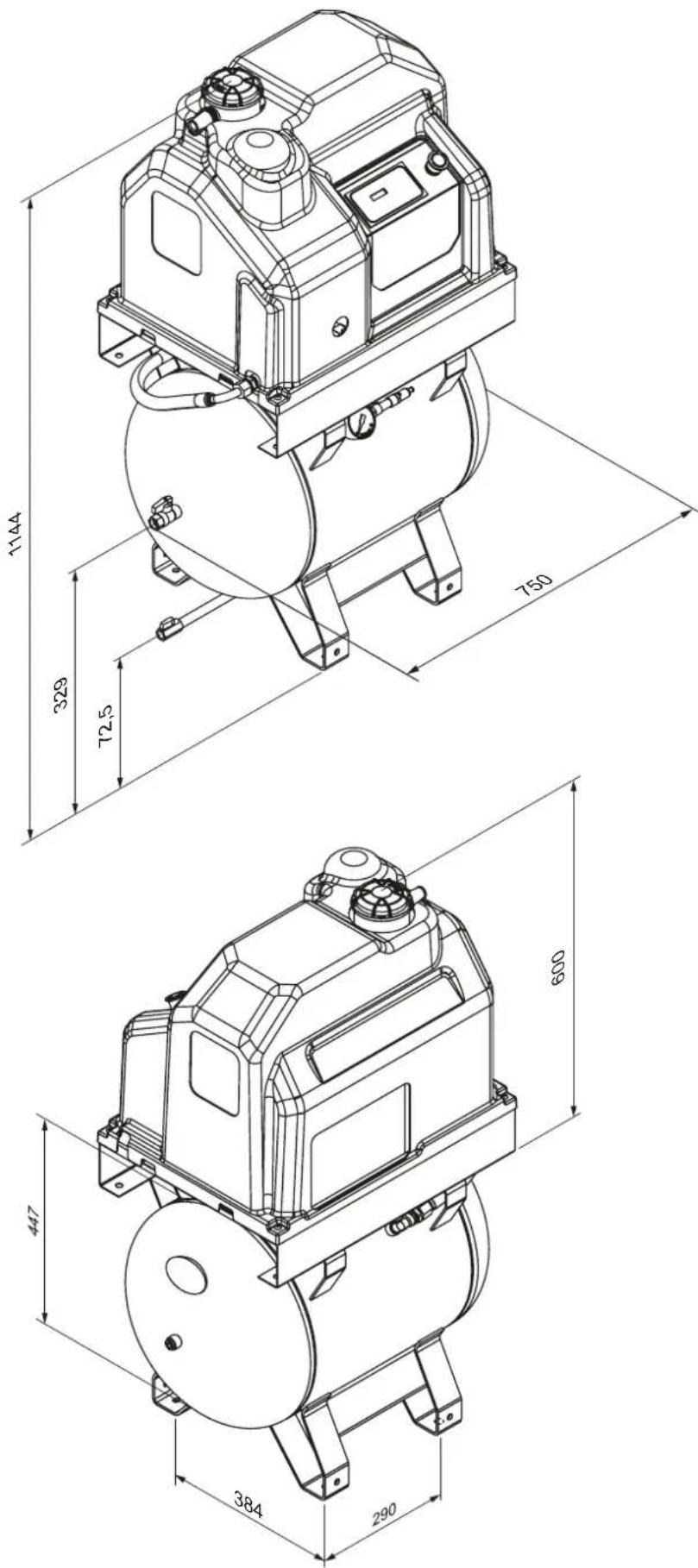
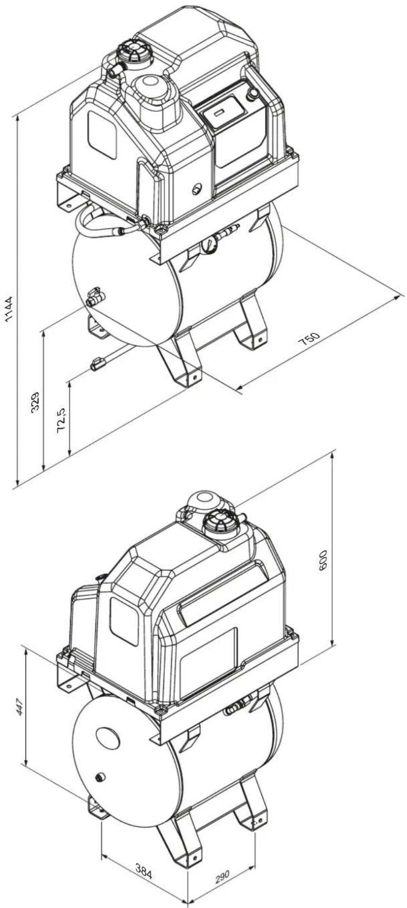
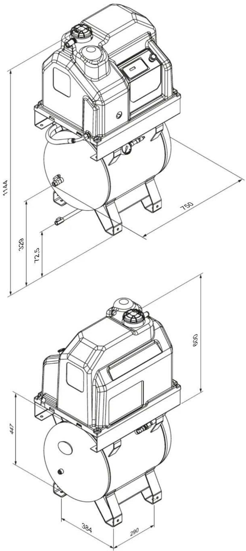
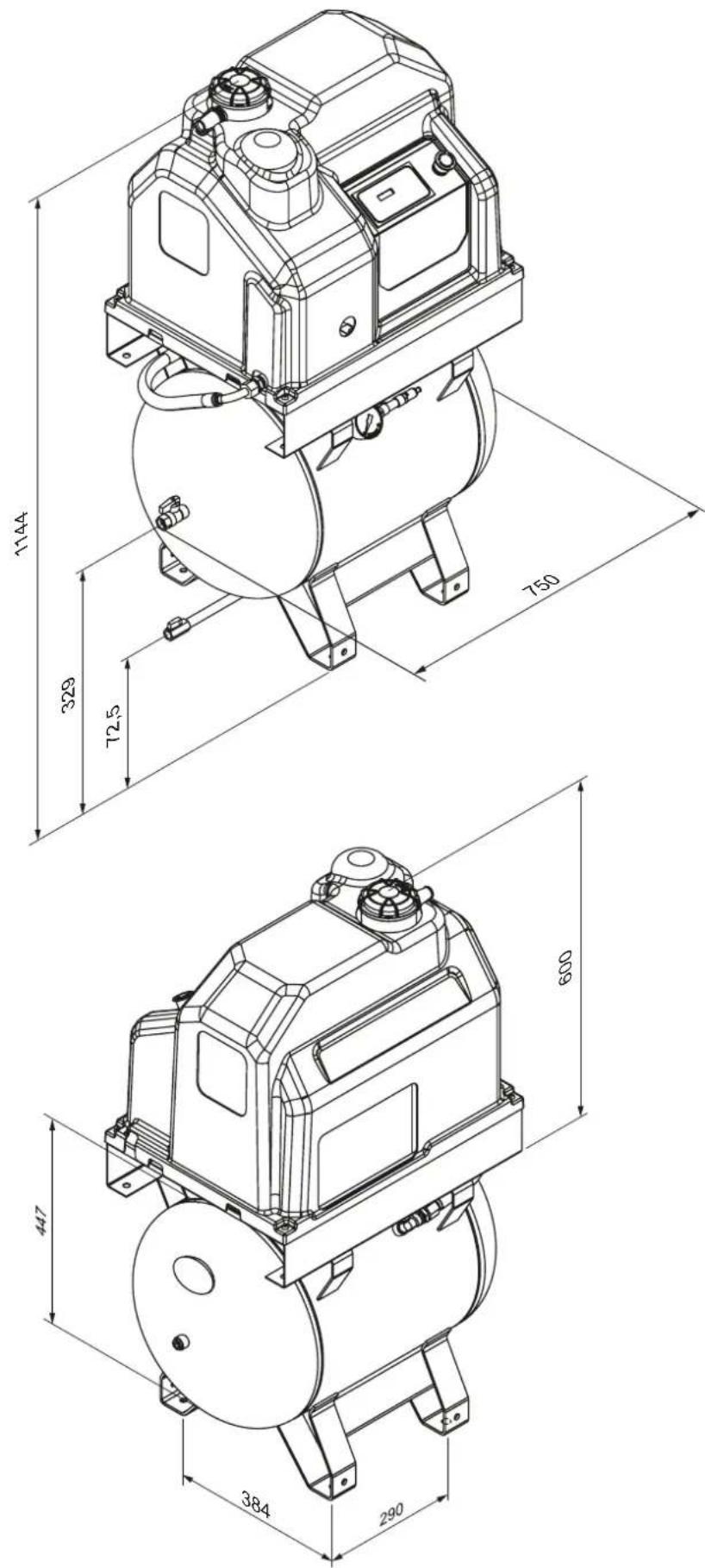
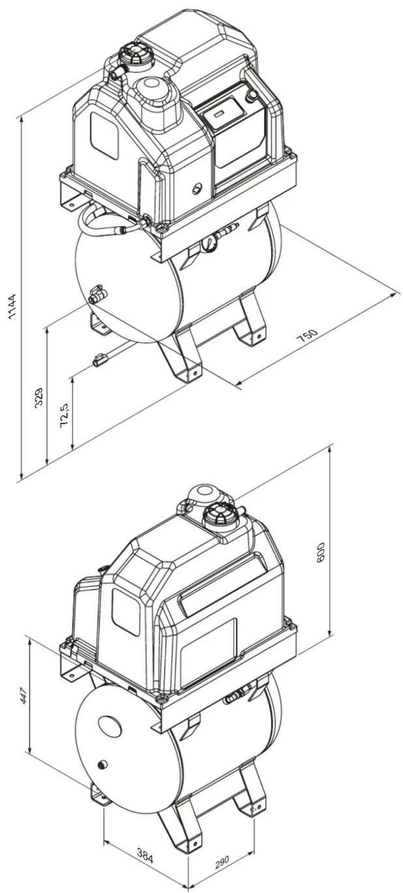
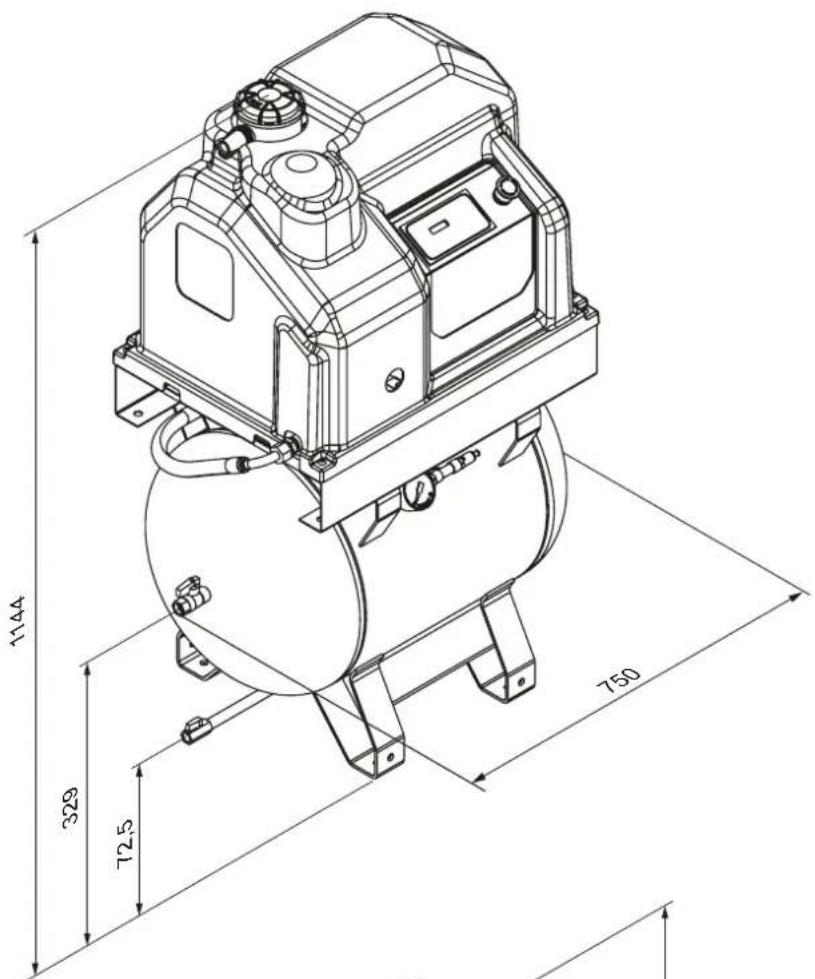
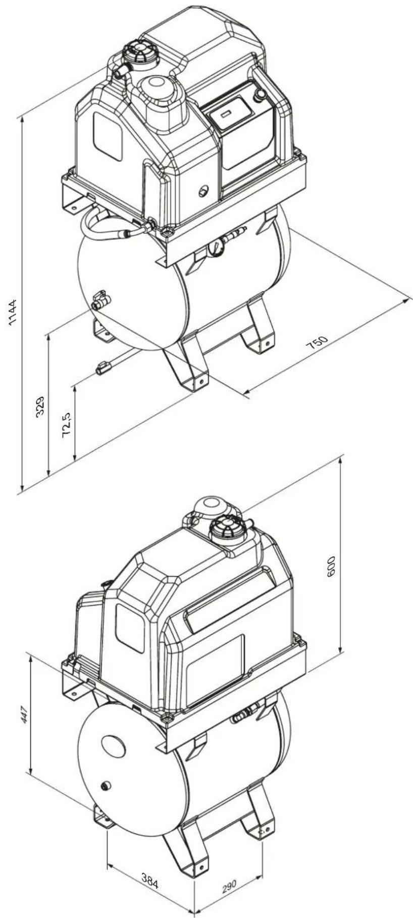
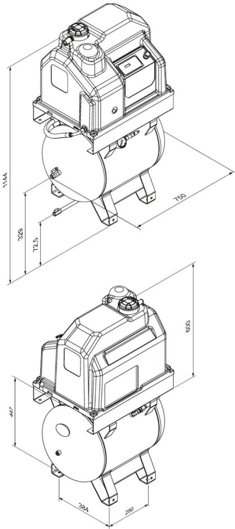
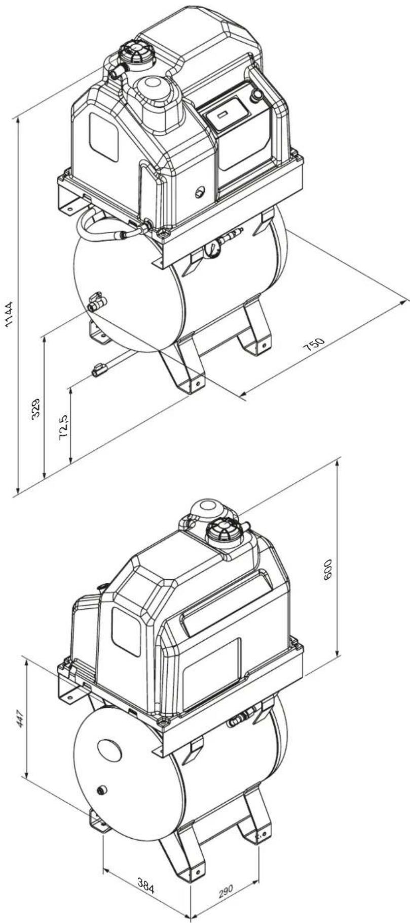
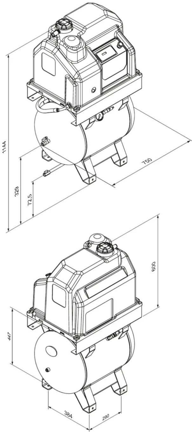
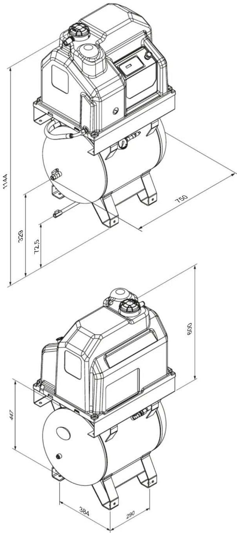
| Dimensions (L x W x H) | 750 x 465 x 1144 mm (with tank) |
| Weight | 105 kg (with tank) |
| Power supply | 230 V / 1~ / 50 Hz or 400 V / 3~ / 50 Hz |
| Motor power | 2.2 kW |
| Maximum current (230 V) | 14.1 A |
| Maximum current (400 V) | 5.2 A |
| Protection rating of electrical enclosure | IP54 |
| Noise level | 65 dB(A) |
| Engine oil quantity | 2.3 L (synthetic type ISO 46) |
| Operating ambient temperature | +2 °C to +45 °C |
| Air outlet | G 1/2" |
| Main functions | Electronic controller with display, alarms, automatic start/stop, pressure adjustment |
| Safety | Safety valve (14 bar), emergency stop, thermal protection, temperature and pressure sensors |
| Routine maintenance | Condensate drain (50 h), oil check (500 h), radiator cleaning (500 h), air filter replacement (1000 h) |
| Repairability | Oil filter, oil separator filter, solenoid valve, replaceable valves |
| Included accessories | Anti-vibration pads, oil/condensate drain hose |
| Warranty | Consult dealer; legal duration of 2 years |
Frequently Asked Questions - APS 3 Combi Compact Airpress
User questions about APS 3 Combi Compact Airpress
0 question about this device. Answer the ones you know or ask your own.
Ask a new question about this device
Download the instructions for your Compressor in PDF format for free! Find your manual APS 3 Combi Compact - Airpress and take your electronic device back in hand. On this page are published all the documents necessary for the use of your device. APS 3 Combi Compact by Airpress.
USER MANUAL APS 3 Combi Compact Airpress
natural_image
Exterior view of two air pressure machines (AirPress and compressoren) with control knobs and gauges, no visible text or symbols on the main body.APS 3 COMBI COMPACT

WARNING! - UWAGA! - ATTENTION! - WAARSCHUWING! - ACHTUNG! - MEGJEGYZÉS! - ATENTIE! - UPOZORNENIE! - BRÍDINÁJUMS! - DÉMESIO! - PAŽNJA! - VÝSTRAHA! - HOIATUS! - NOTAI! - NOTAI- ¡ATENCIÓN! - YBÁΓA! - HUOM! - ADVARSELI! - BHI Hungary! - KĚRKO! - UPLATAI - VARNING! - ADVARSELI! - OPOZORILO!
EN | Preserve this handbook for future reference.
PL | Zachowaj ten podręcznik na przyszłość.
FR | Conserver le présent manuel pour pouvoir le consulter ultérieurement.
NL | Bewaar deze handleiding voor toekomstige raadpleging.
DE | Diese Bedienungsanleitung für späteres Nachschlagen sorgfältig aufbewahren.
HU | Tartsa meg ezt a használati útmutalót a későbbi használatra.
RO | Pästrați acest manual pentru consultân ulterioare.
SK | Uschovajte si tuto priručku pre budúce použitie.
SI | Shrani to priročnik za kasnejšo referenco.
LV | Uzglabājiet śo lietośanas pamācību turpmākai lietośanai.
LT | Saugokte ši naudojimo vadovą, kad galetuimėte juo naudotis ateltyje.
HR | Sačuvajte ovaj priručnik s uputama za buduću upotrebu.
CZ | Uschovejte tuto příručku pro budoucí potřebu.
EE | Hoida käesolev kasutusjuhend edaspidiseks kasutamiseks alles.
IT | Conservare il presente manuale di istruzioni per future consultazioni.
PT | Guarde este manual de instruções para referência futura.
ES | Guarde el manual para futuras consultas.
UA | Зберігайте цю інструкцію для подальшого використання.
FI | Süilytä tärmä käyttöuhje myöhempää käyttöä varten.
NO | Behold denne håndboken for fremtidig referanse.
MK | Зачувајте го овој прирачник за идни референци.
QA | Ruajeni këtë manual për referencë të ardhshme.
SR | Zadržite ovaj priručnik za buduće reference.
SV | Spara denna handbok för framtida referens.
DK | Behold denne vejledning til fremtidig reference.
EN KEY TO PRODUCT SAFETY SIGNS
PL LEGENDA ZNAKÓW OSTRZEGAWCZYCH NA WYROBACH
FR LÉGENDE DES PICTOGRAMMES DE SÉCURITÉ FIGURANT SUR LES PRODUITS
NL VERKLARING WAARSCHUWINGSSYMBOLEN OP PRODUCTEN
EN | Hearing, sight and respiratory protection must be worn.
SV | Farlig spänning.
EN | Warning, hot surfaces.
EN | Before use, read the handbook carefully.
DECLARATION OF CONFORMITY
This declaration is attached to the air compressor in the original copy.
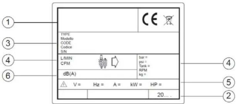
All identification data (producer, model, code, and serial number) are stamped on the CE label.
For any request for copies, it is ESSENTIAL to provide ALL data stamped on the CE label.
EN
The producer declares under its sole responsibility that the compressor described above complies with all relevant regulations of the following EU directives: 2006/42/EC, 2014/30/EU, 2011/65/EU.
The following harmonised standards have been applied in the latest version published on the Official Journal of the European Union: EN 1012-1, EN 60204-1, EN 61000-6-2, EN 55011.
TABLE OF CONTENTS
- GENERAL INFORMATION
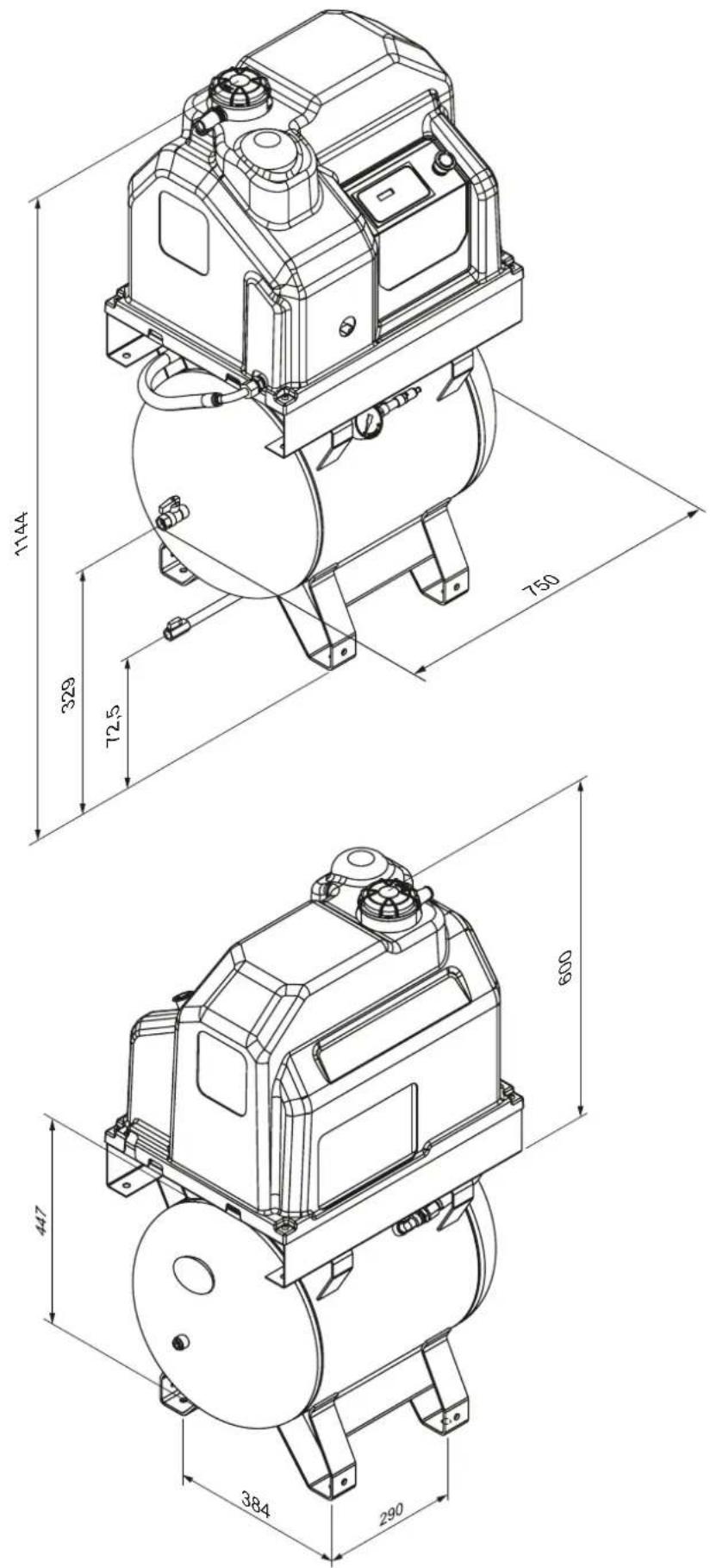
- OVERALL DIMENSIONS (IN MM)
- SAFETY REGULATIONS
- INSTALLATION
- TECHNICAL DATA
- CONTROLS AND SETTINGS
- ALARMS
- OPERATION
- MAINTENANCE
- TROUBLESHOOTING
- WIRING DIAGRAM
1. GENERAL INFORMATION
STANDARD EQUIPMENT
The following accessories are supplied with the compressor:
• operating and maintenance manual
• anti-vibration pads
• oil/condensate drain pipe
Please check that the above accessories are available upon delivery and acceptance. Once the goods have been delivered and accepted, no complaints will be accepted.
MACHINE CONDITION AT THE TIME OF DELIVERY
Each compressor is tested under workshop conditions and delivered ready for installation and commissioning.
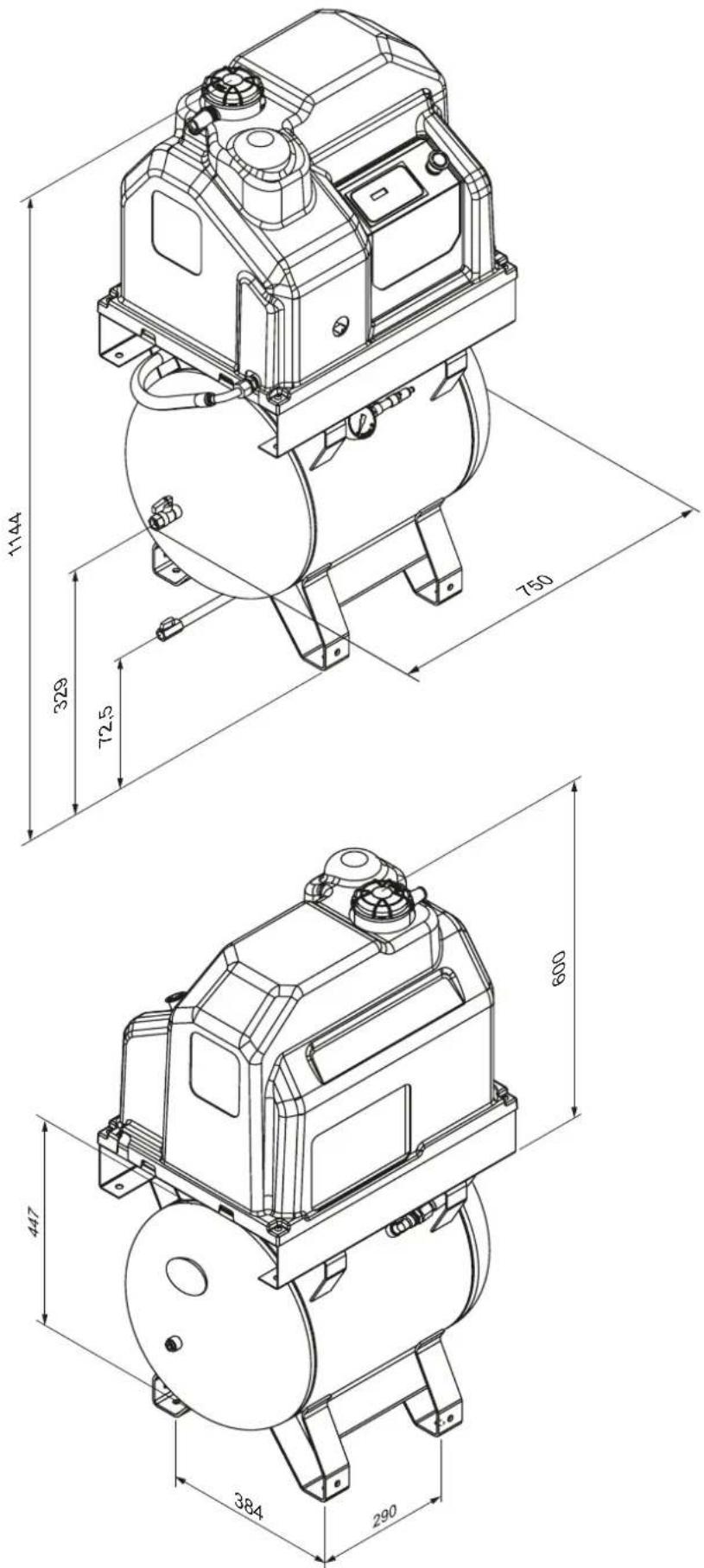
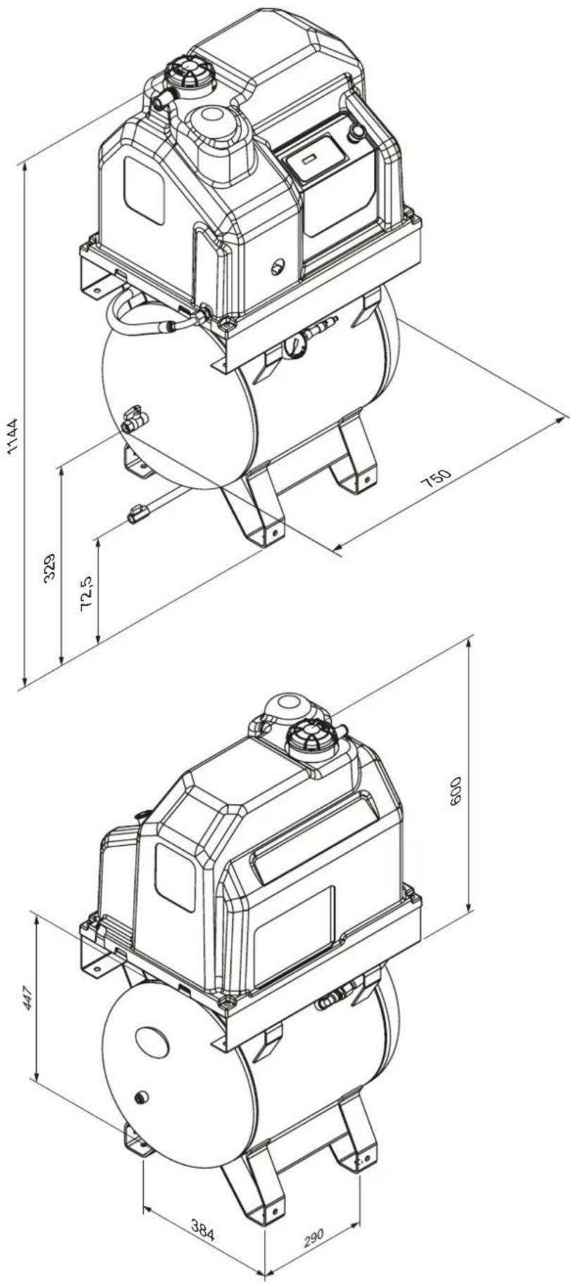
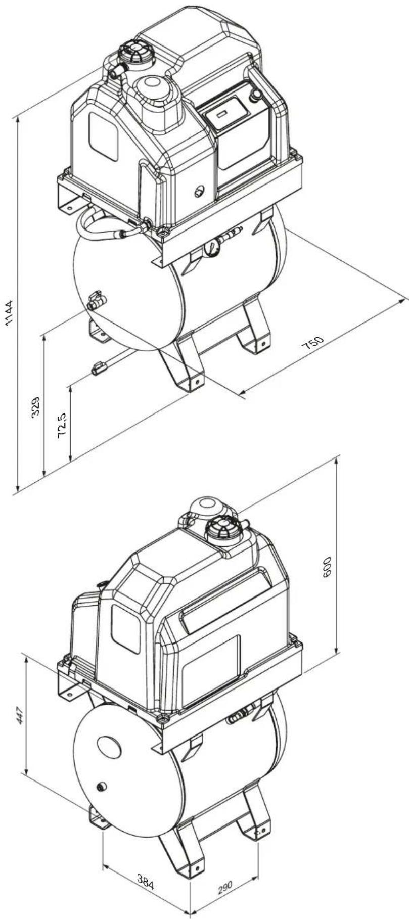
2. OVERALL DIMENSIONS (IN MM)
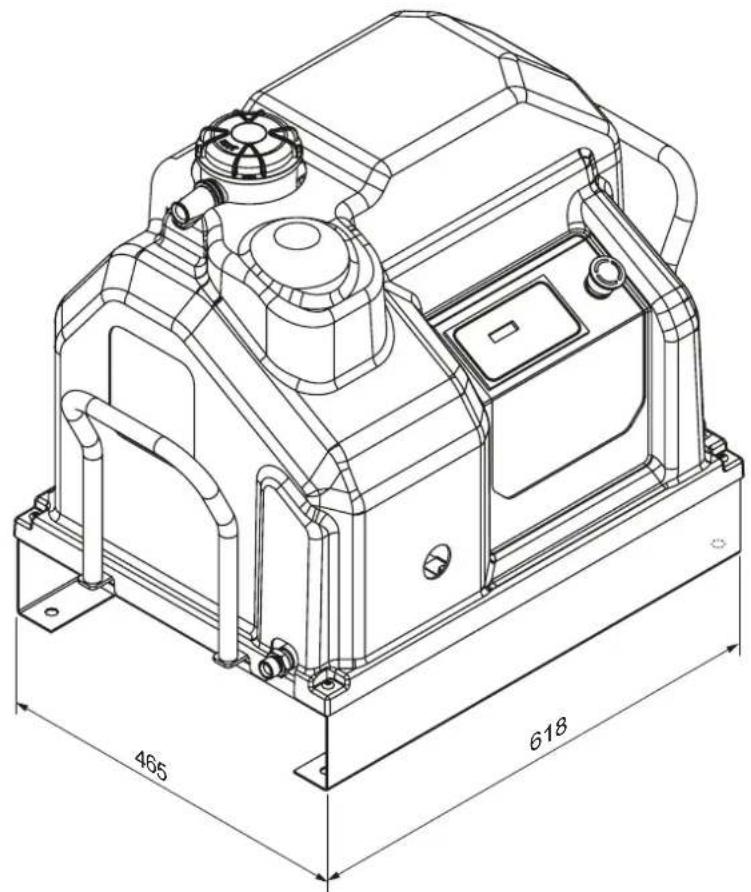
natural_image
Technical line drawing of a mechanical device with dimension annotations (465 and 618), no readable text or symbols beyond measurement lines.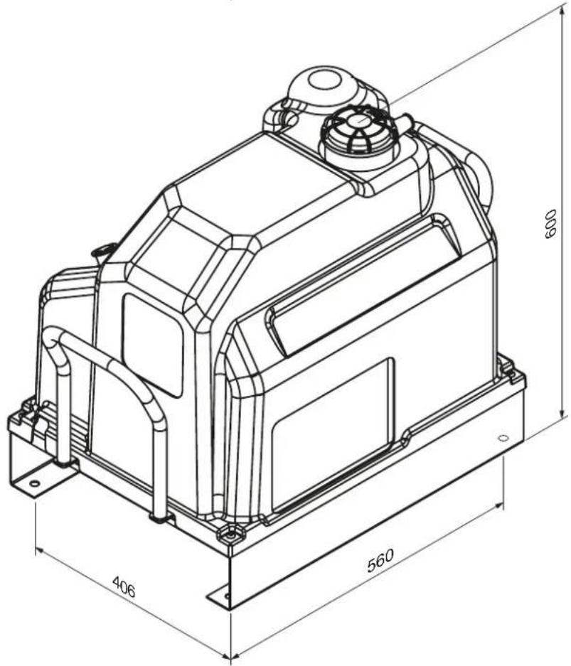
3. SAFETY REGULATIONS
GENERAL WARNINGS
- Screw compressors are intended for heavy continuous industrial use. They are especially suitable for industrial applications requiring high air consumption over a long period.
- The compressor should be operated only in compliance with the instructions provided in this manual. Keep this manual in a known and easily reachable place throughout the compressor working life.
- A supervisor should be appointed within the company where the compressor is installed. This person should be responsible for compressor inspections, adjustments, and maintenance. Should a substitute be appointed for the supervisor, s/he must carefully read this operating and maintenance manual, as well as any remarks about prior service and maintenance carried out.
SYMBOLS USED IN THIS MANUAL
Some symbols are used to highlight dangerous situations, provide recommendations, or indicate important information. These symbols are usually positioned next to relevant text, figures, or at the top of a page (indicating that the symbols apply to all topics discussed on that page). Please read the meanings of the below symbols carefully.

WARNING!
Important description of service, dangerous situations, safety measures, accident prevention recommendations, and/or critical information.

POWER OFF!
All operations must only be carried out when the power is switched off.

MACHINE STOPPED!
All operations indicated by this symbol must be strictly carried out only the machine has been stopped.

SPECIALIZED PERSONNEL!
All operations marked with this symbol must only be carried out by qualified technical personnel.
SYMBOLS SIGNED ON THE COMPRESSOR
There are stickers on the compressor indicating potential hazards and correct operating procedures in such situations. It is essential to comply with these instructions.
Warning symbols Prohibition symbols

High temperature risk

Do not open doors when the machine is operating

Electric shock risk

If necessary, always use the emergency stop button and NOT the line breaker

Risk from hot or dangerous gases in the work area

Do not use water to extinguish fires on electrical equipment

Pressurised container Obligation symbols

Moving mechanical parts

Carefully read this manual.

Maintenance in progress

Machine with automatic start-up
Read this page carefully before operating the compressor.
TO DO:
Make sure that the mains voltage corresponds to the voltage indicated on the CE label and that cables with the appropriate cross-section are used for electrical connections.
Always check the oil level before starting the compressor.
Understand how to stop the compressor rapidly and familiarize yourself with the operation of all controls.
Turn off the power before performing any maintenance work to avoid accidental starting.
Ensure that all parts are correctly reassembled after any maintenance.
Keep children and animals away from the working area to avoid injuries caused by devices connected to the compressor.
Ensure that the working environment temperature remains between +5°C and +50 °C.
The compressor must be installed and operated in a non-explosive environment and away from flames.
Allow at least 80 cm of space between the compressor and the wall to ensure proper airflow to the fan. Press the emergency button on the control panel only in case of an actual emergency to avoid potential injury to people or damage to the compressor.
When requesting technical assistance and/or advice, always mention the model, code, and serial number indicated on the CE label.
Always follow the maintenance schedule specified in the manual.
NOT TO DO:
Do not touch internal parts and pipes as they become very hot during compressor operation and remain hot for some time after the compressor stops.
Do not place flammable items or nylon and cloth items near or on top of the compressor.
Do not move the compressor when the tank is under pressure.
Do not operate the compressor if the power cable is damaged or defective, or if the connection is unstable.
Do not operate the compressor in wet or dusty environments.
Never aim the air jet at people or animals.
Do not allow anyone to operate the compressor without first providing them with all required instructions.
Do not strike the fans with blunt or metal objects as they may break during compressor operation.
Never operate the compressor without an air filter and/or pre-filter.
Do not tamper with safety and adjustment devices.
Never operate the compressor when doors or panels are open or removed.
PRODUCT IDENTIFICATION
The compressor you have purchased is identified by the CE label, which displays the following data:
-
Producer's data.
-
Year of manufacture.
-
TYPE = name, CODE = code, SERIAL NO. = serial number (this must always be provided when calling for technical assistance).
-
Technical data: air delivery, max. operating pressure, tank capacity, rotations per minute, and weight.
-
Electrical data: voltage, frequency, absorption, power.
-
Noise level.
- INSTALLATION
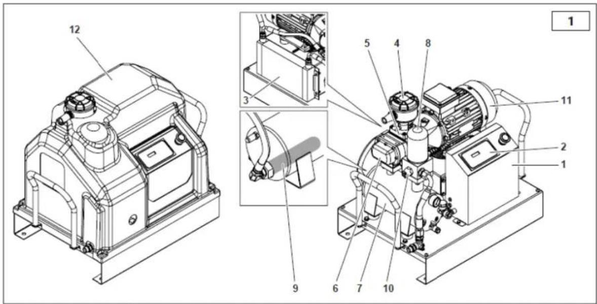
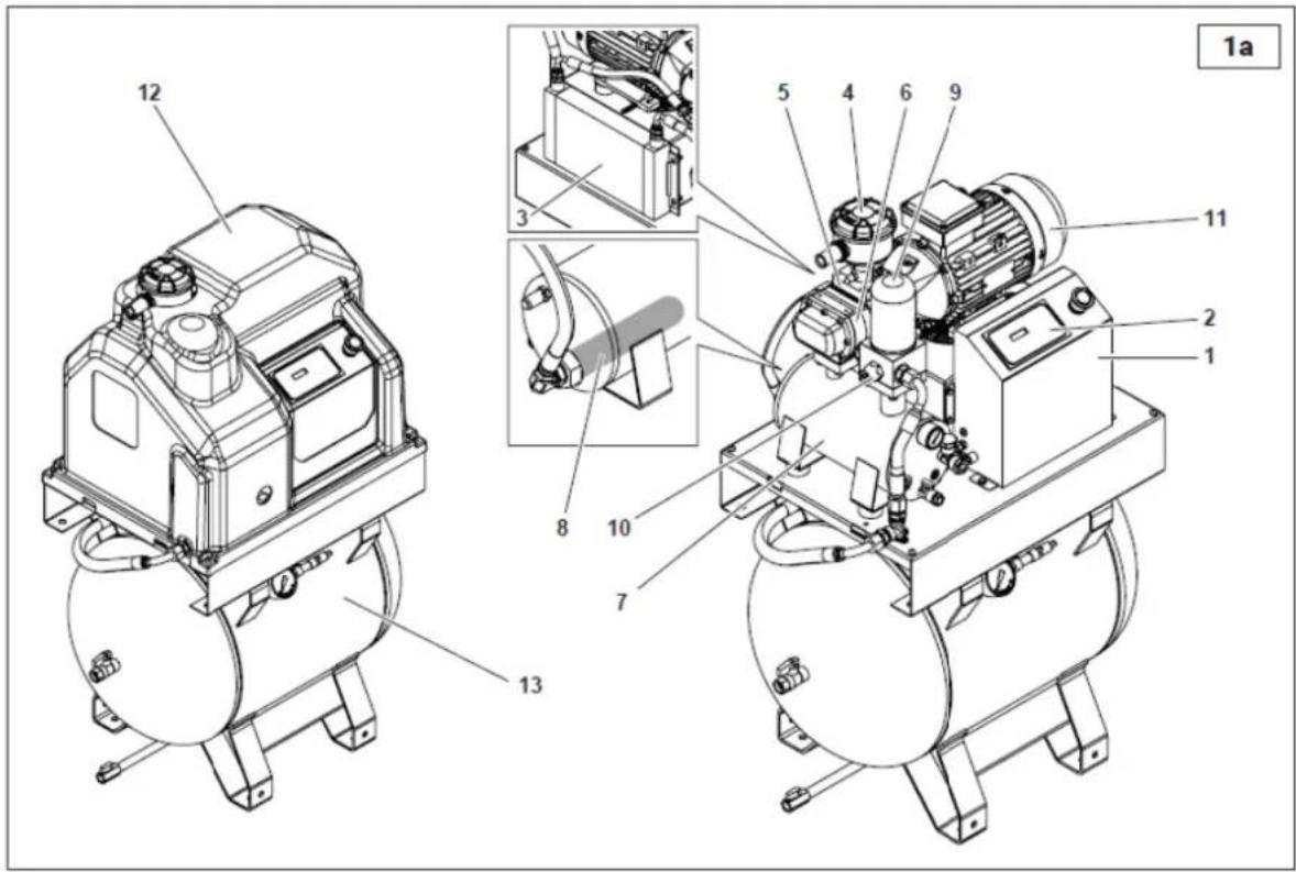
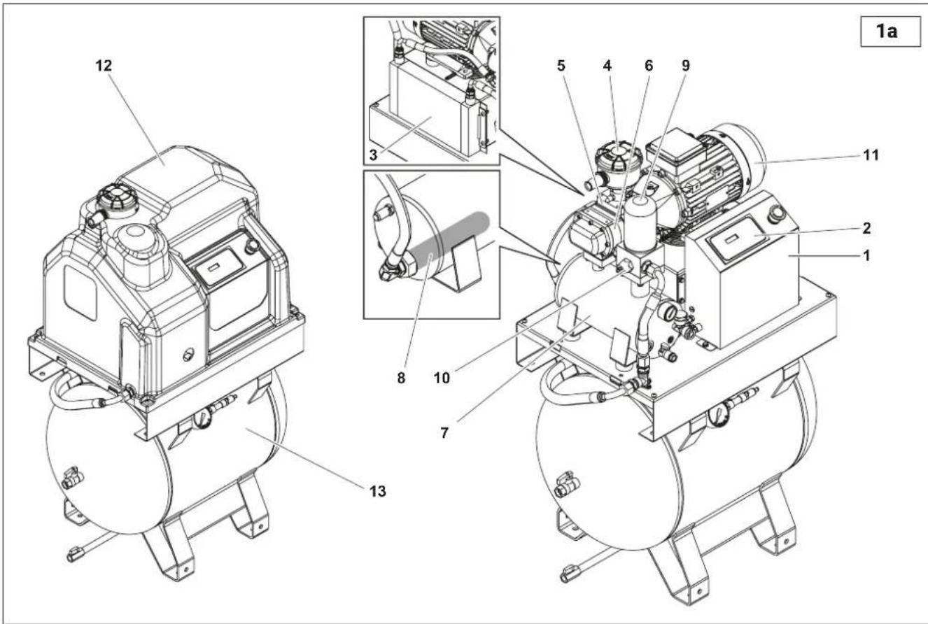
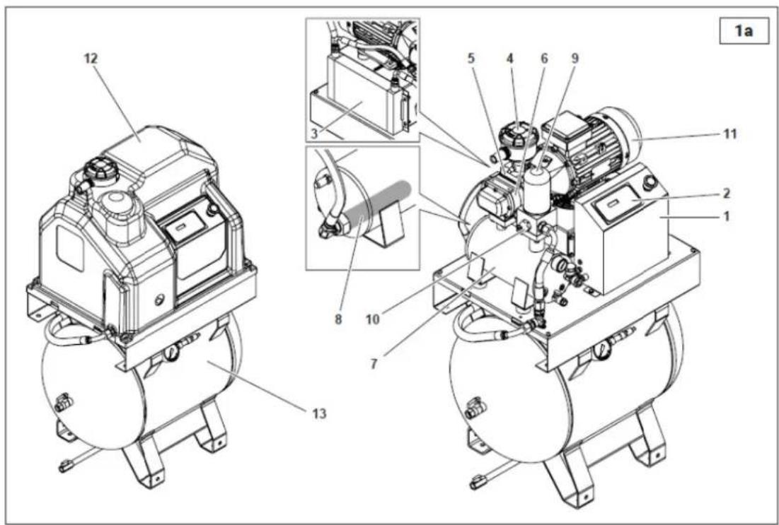
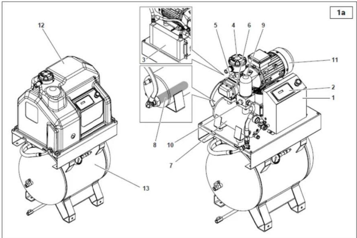
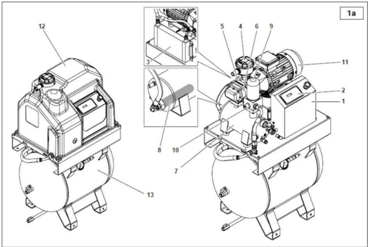
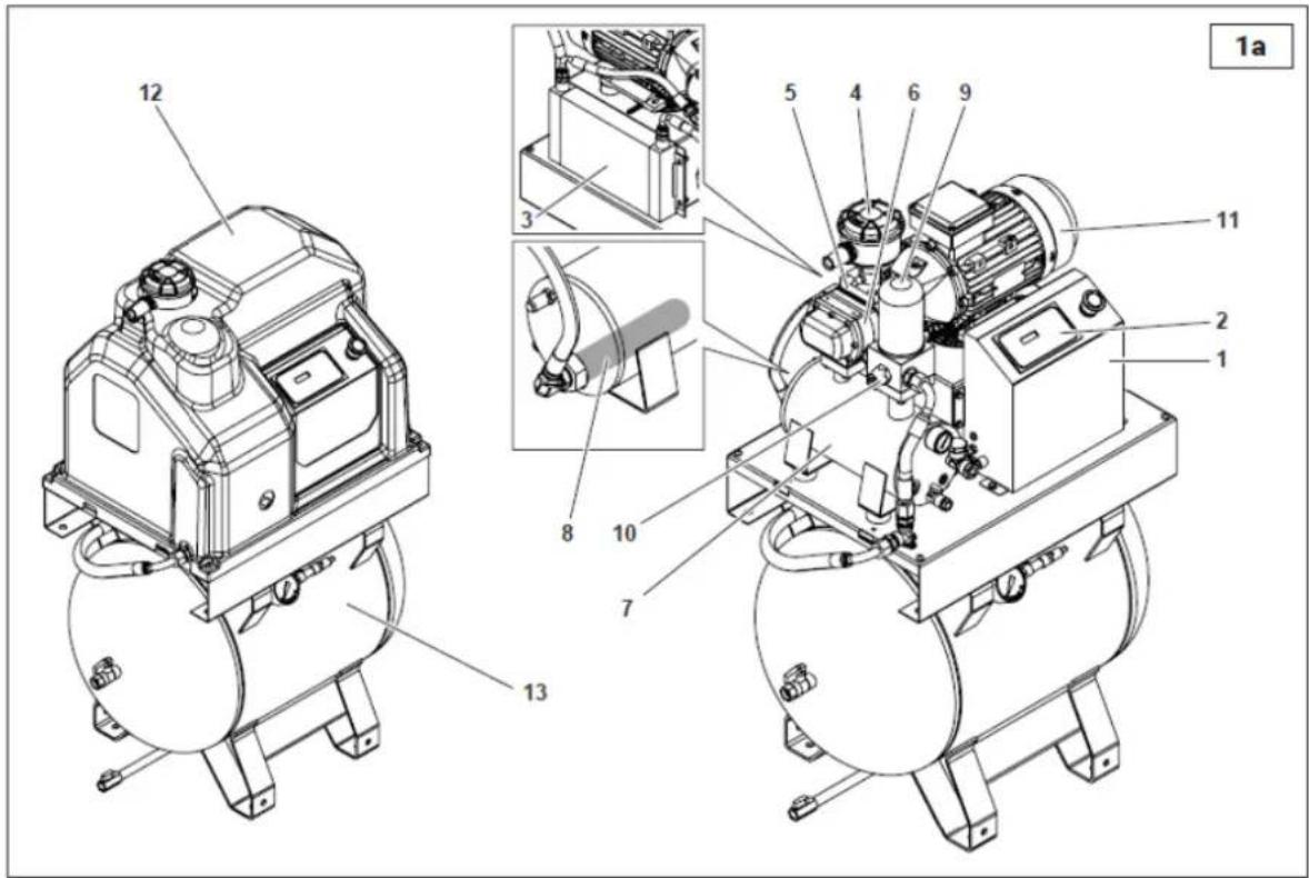
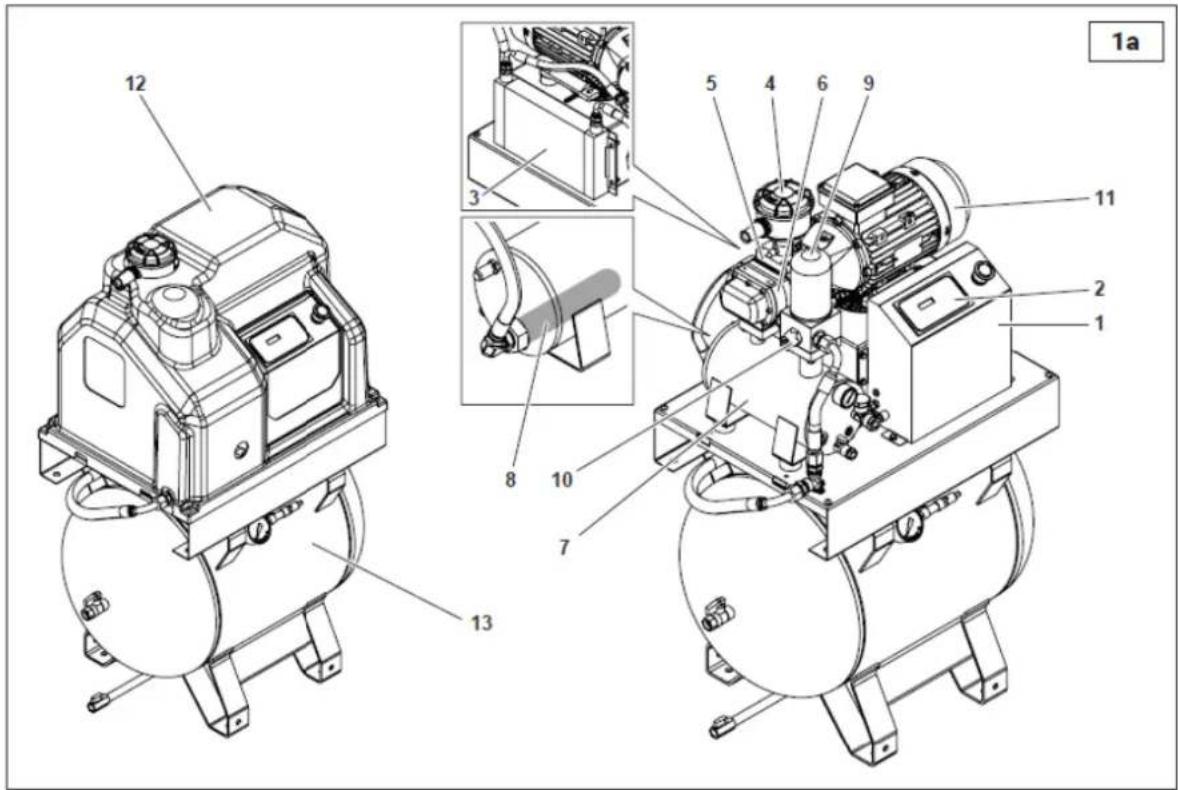
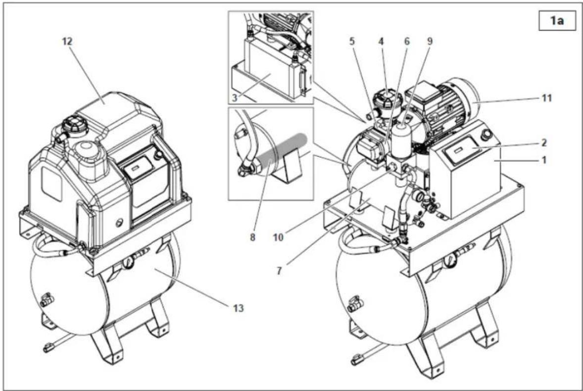
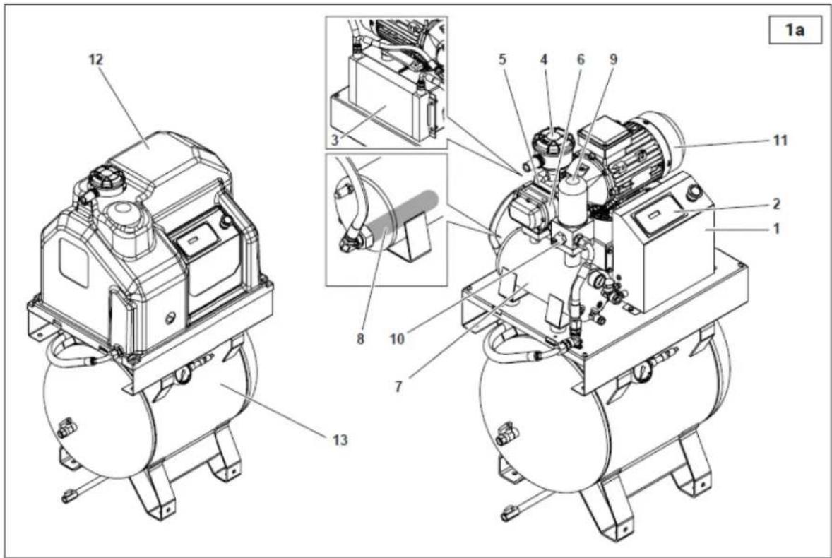
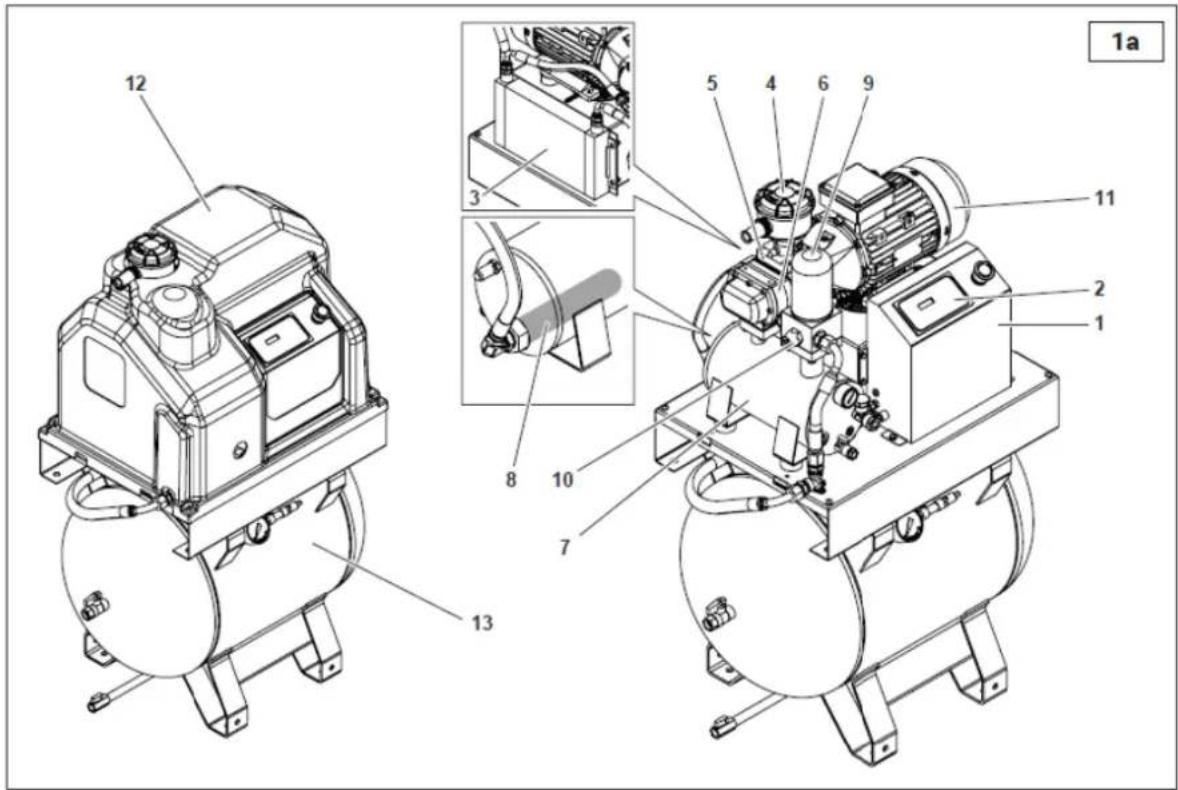
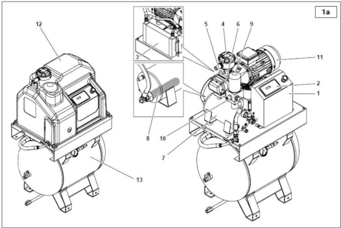
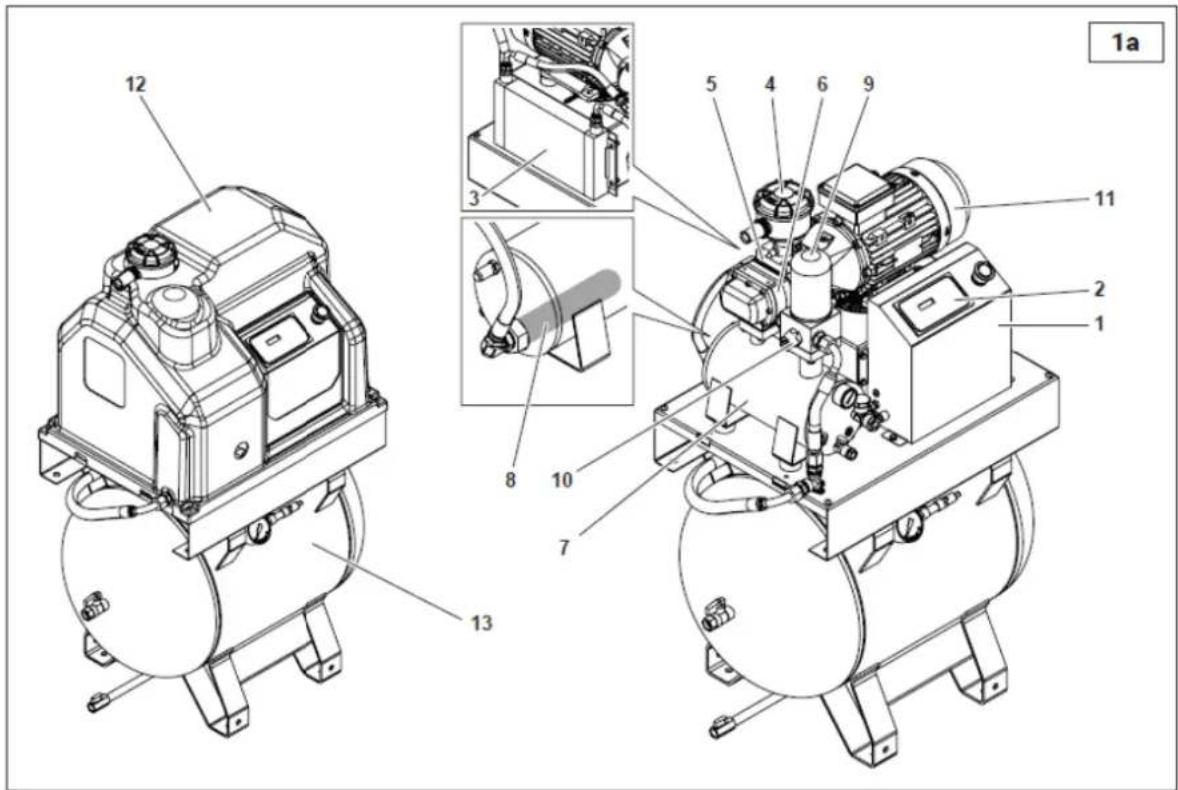
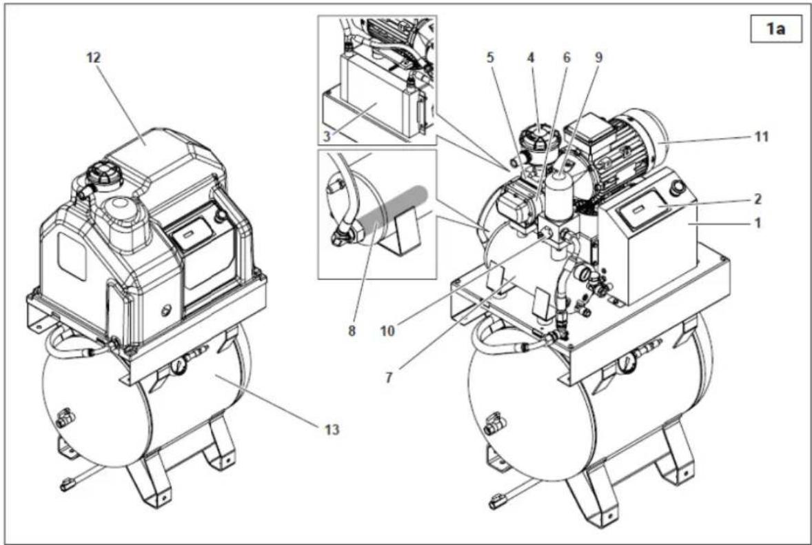
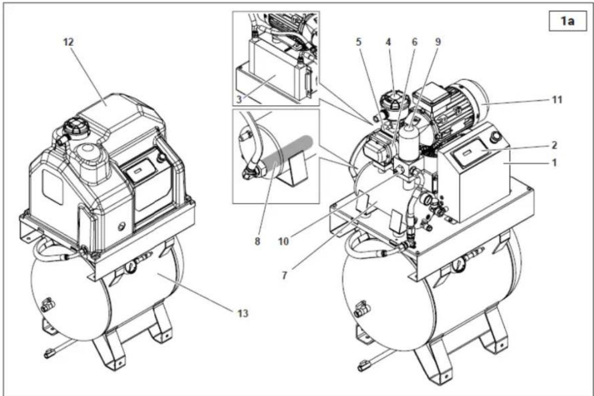
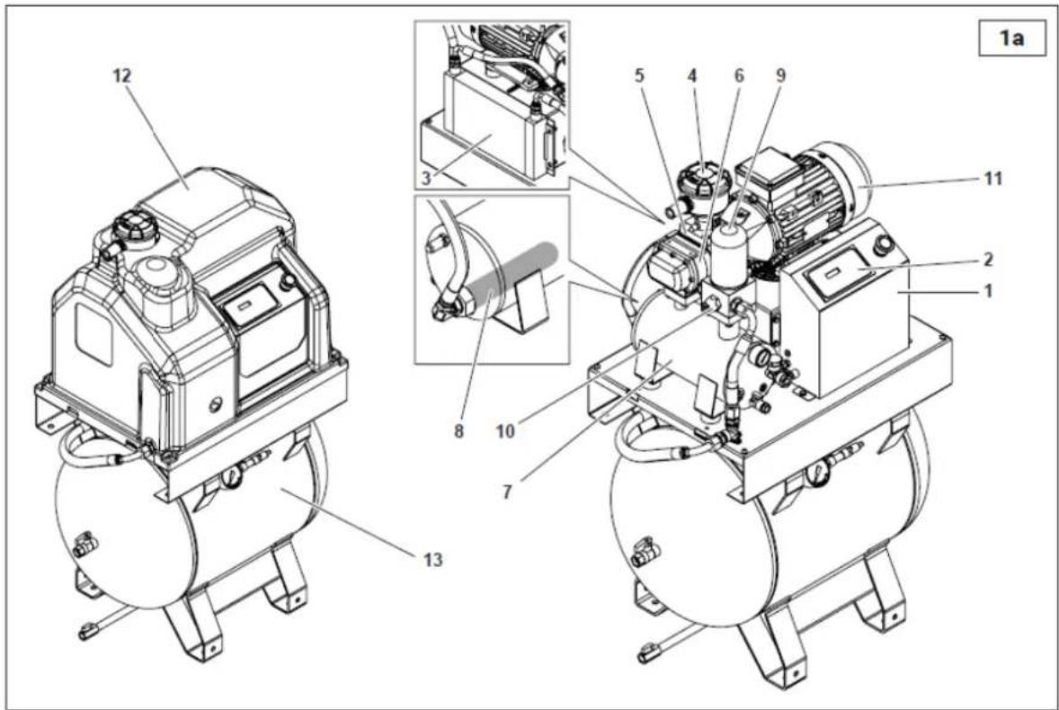
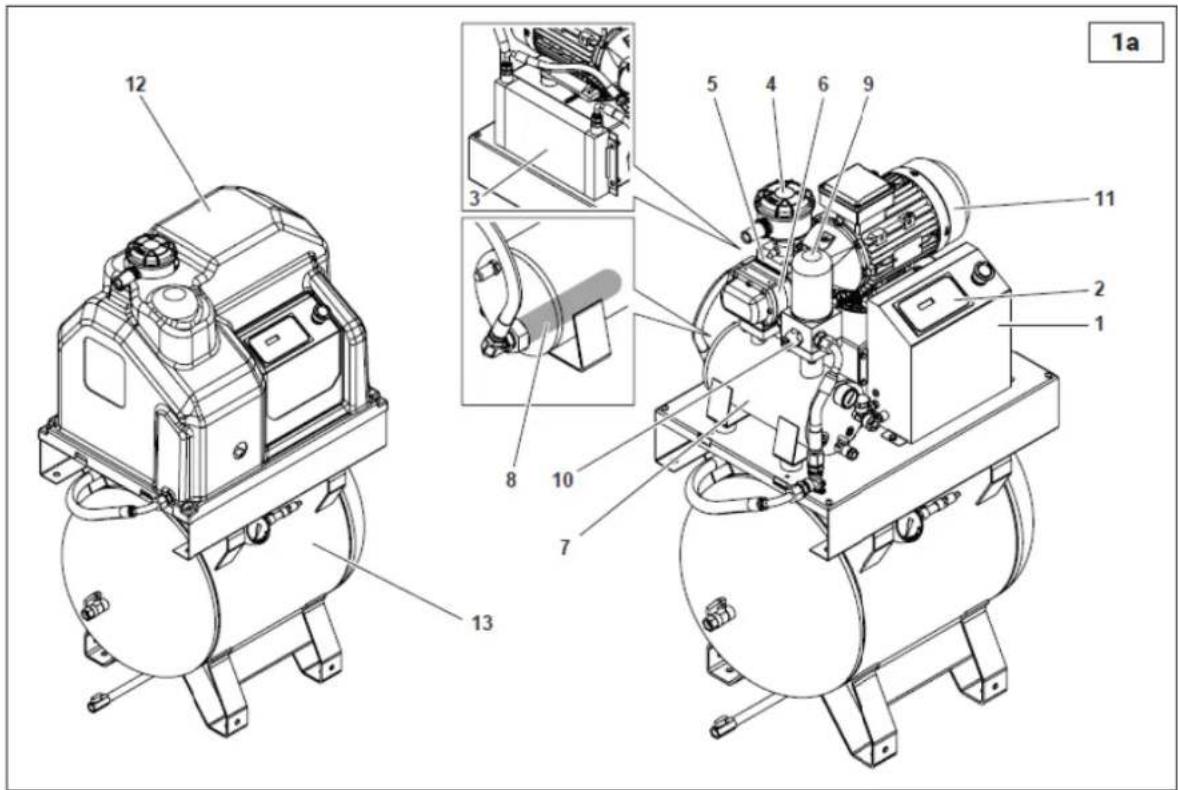
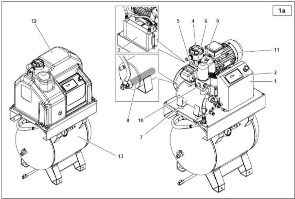
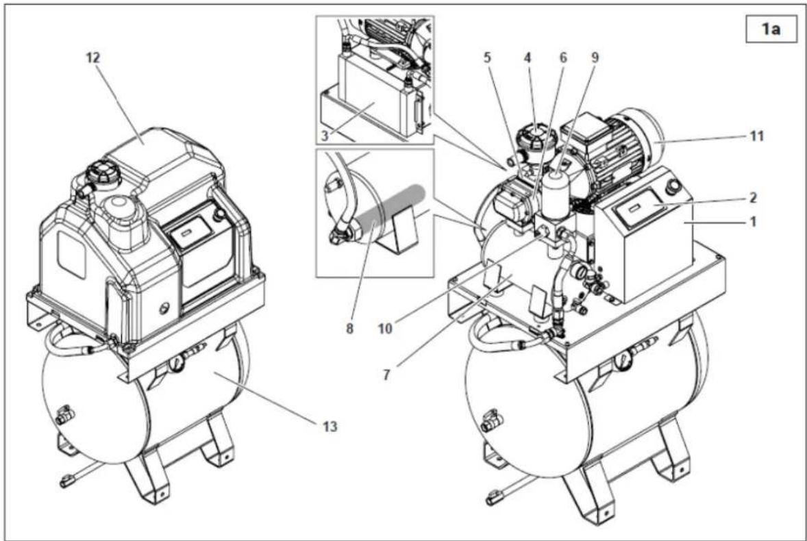
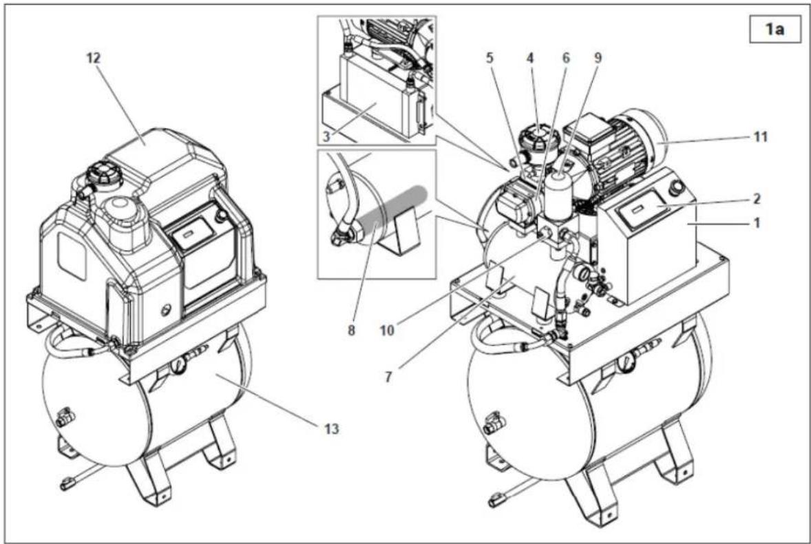
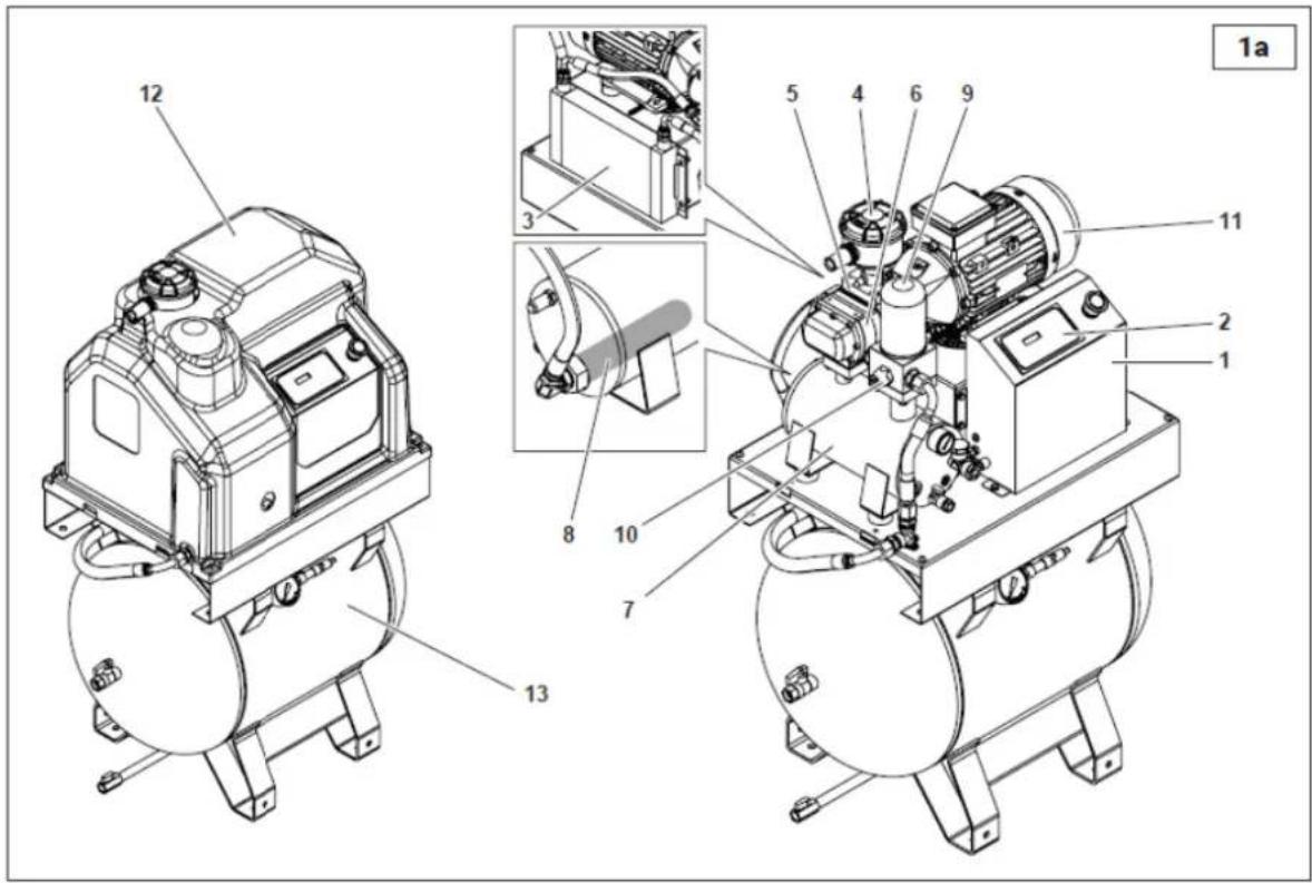
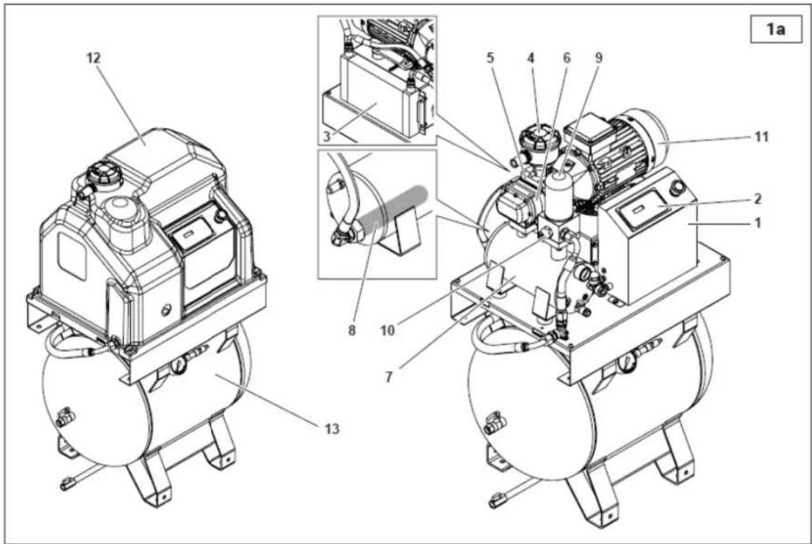
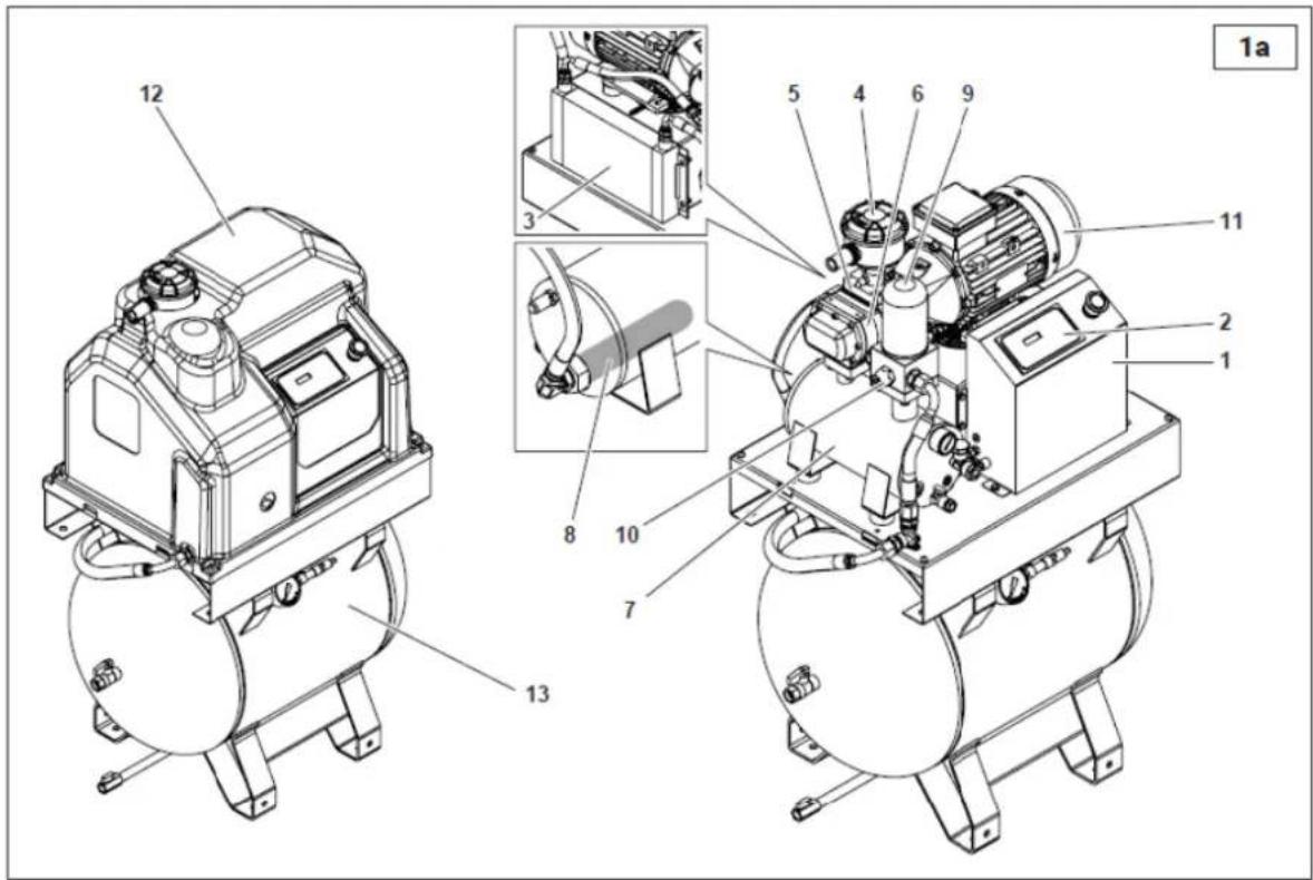
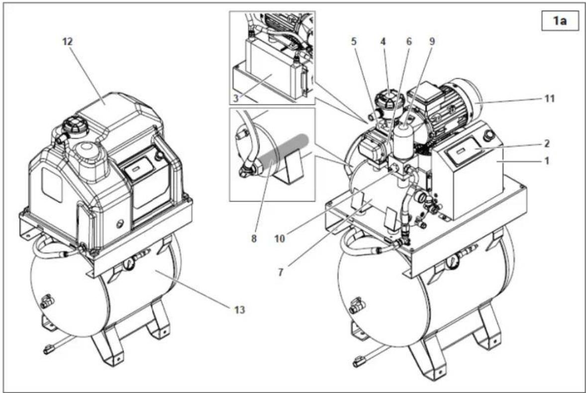
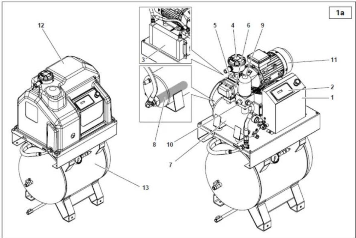
COMPRESSOR DESCRIPTION (Fig. 1-1a)
The compressor consists essentially of the following components:
- Electrical equipment
- Oil filter
- Electronic controller
- Oil separator filter
- Oil cooler
- Minimum pressure valve
- Air intake filter
- Electric motor
- Suction regulator
- Housing
- Screw module
- 90-litre air tank
- Oil separator
UNPACKING AND ASSEMBLY
When delivered, the compressor top is protected by cardboard packing.
Wear suitable protective gloves to remove the outer straps and cardboard. Check the machine condition before moving it. Ensure no parts are damaged and that all accessories are included.
Use a forklift to lift the machine. Place anti-vibration pads in their proper position and move the compressor carefully to its designated location.
Keep all packaging materials for at least the warranty period for future movement, as it may be needed when shipping to the technical support.
Dispose of packaging materials according to local regulations.
LOCATION (Fig. 2)
Remove the compressor from the wooden pallet used for transport and position it on the floor, using shock-absorbers if supplied. The wooden pallet is used for transport purposes only and should not be kept under the machine during operation.
The room chosen for the installation of the compressor should meet the following requirements and comply with what is specified in the current safety and accident prevention regulations:
• A low percentage of dust in the air
- Proper room ventilation and a size that ensures the room temperature remains under 50°C. In case of inadequate hot air discharge, install exhaust fans as high as possible.
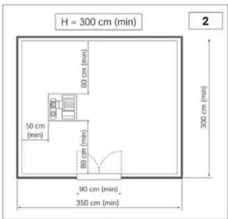
Condensate should be collected in a pit or a tank.
The room dimensions are provided as guidelines, but it is recommended to follow them as closely as possible.
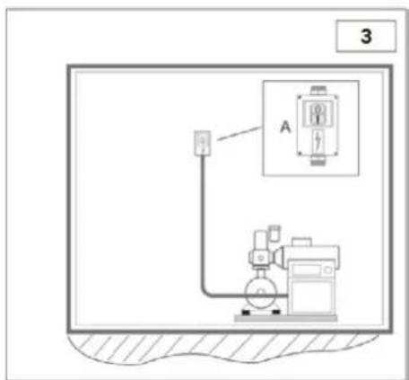
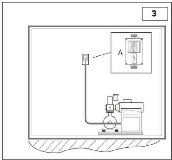
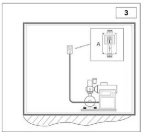
ELECTRICAL CONNECTION (Fig. 3)
- Ensure that the mains cable has an adequate cross-section for the compressor power and includes the no. 3 phase wires and no. 1 earth wire.
• Install a fused or magnetothermal switch near the cable entry point into the machine, between the mains cable and the compressor control panel. - The switch (A) should be easily accessible for the operator. Ensure the cables used are of appropriate type and have the appropriate protection (minimum IP44 rating).
NOTE: To determine the cable cross-section, follow sizing guides for the cables, based on the VDE 0100 Standard (Parts 430 and 523), ensuring the presence of a star-delta starter, that the room temperature is 30^ C and the cable does not exceed 50 metres.
If the compressor has been stopped for more than 30 days, it is necessary to manually add some oil into the air-end to insure it is lubricated during the first start, as described in the "Screw Compressors - Fast Start-up". Failing to comply with this procedure could lead to seizing of the air-end. Contact your supplier for more details.
- TECHNICAL DATA
| Technical characteristics | Type | 2.2 M | 2.2 | ||
| Operating pressure | bar g | 8 | 10 | 8 | 10 |
| Pumping unit | type | FS 14 | |||
| Air delivery (ISO 1217 annex C) | L/min | 292 | 261 | 292 | 261 |
| Oil quantity | L | 2,3 | |||
| Quantity of top up oil | L | 0,3 | |||
| Maximum final air overtemperature | °C | 3 | 3 | ||
| Removed heat | kJ/h | 7524 | 7524 | ||
| Fan flow rate | m3/h | 600 | |||
| Oil residuals in air | mg/m3 | 2 - 4 | |||
| Electric motor | type | 90 MC/2 | 90 MC/2 | ||
| Rated power | kW | 2,2 | 2,2 | ||
| Maximum input power from mains including ventilation | kW | 2,7 | 3,1 | 2,7 | 3,1 |
| Electrical cabinet protection rating | IP | 54 | |||
| Ambient temperature limit | °C | (+)2 – (+)45 | |||
| Sound pressure (according to Neuron/Cagi PN2CPTC2) | dB(A) | 65 | |||
| Electrical data | |||||
| Supply voltage | V / Ph / Hz | 230/1~/50 | 400/3~/50 | ||
| Auxiliary voltage | V / Ph / Hz | 24/1~/50 | |||
| Maximum input current including ventilation | A | 12,2 | 14,1 | 4,5 | 5,2 |
| Electric motor protection, degree of insulation | IP | 55/F | |||
| Service factor | 1 | 1,15 | |||
| Protective devices | |||||
| Oil circuit maximum temperature | °C | 110 | |||
| Oil circuit pre-alarm calibration | °C | 105 | |||
| Motor electronic relay calibration | A | PTC | PTC | ||
| Safety valve calibration | bar | 14 | |||
| Dimensions and weight | |||||
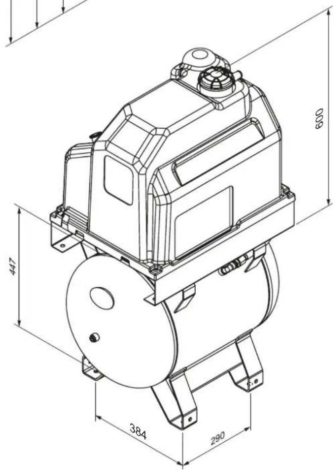
| Length | mm | 618 (765 with handle) | |||
| Width | mm | 465 | |||
| Height | mm | 600 | |||
| Weight | kg | 68 | 68 | ||
| Air outlet | G | 1/2" | |||
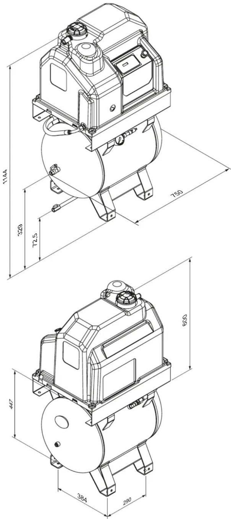
| Dimensions and weight with the 90-litre tank | |||||
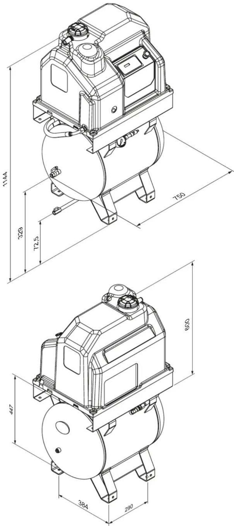
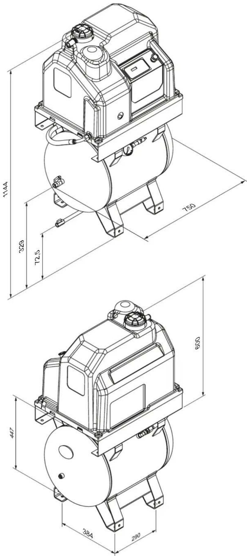
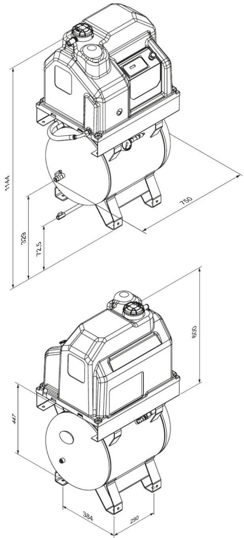
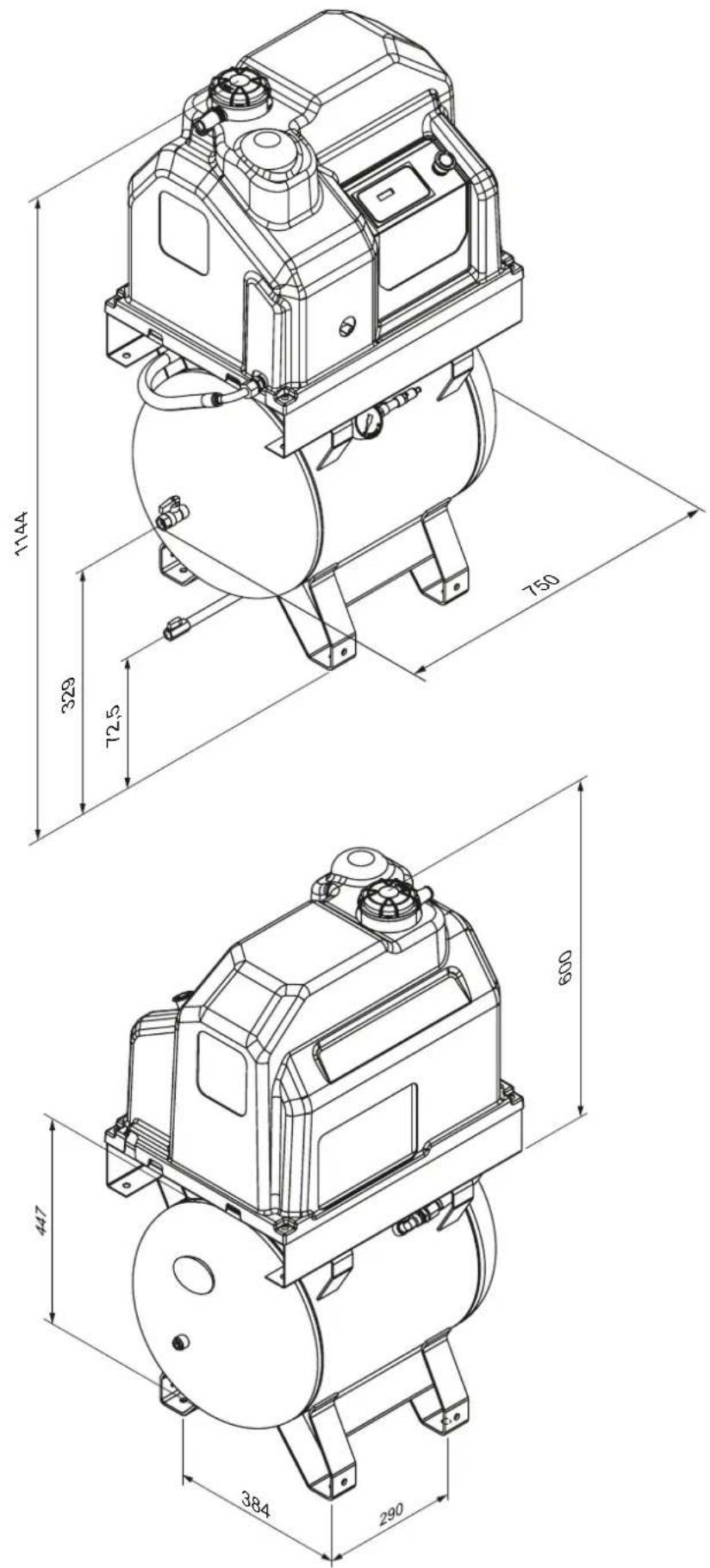
| Length | mm | 750 | |||
| Width | mm | 465 | |||
| Height | mm | 1144 | |||
| Weight | kg | 105 | 105 | ||
| Air outlet | G | 1/2" | |||
6. CONTROLS AND SETTINGS
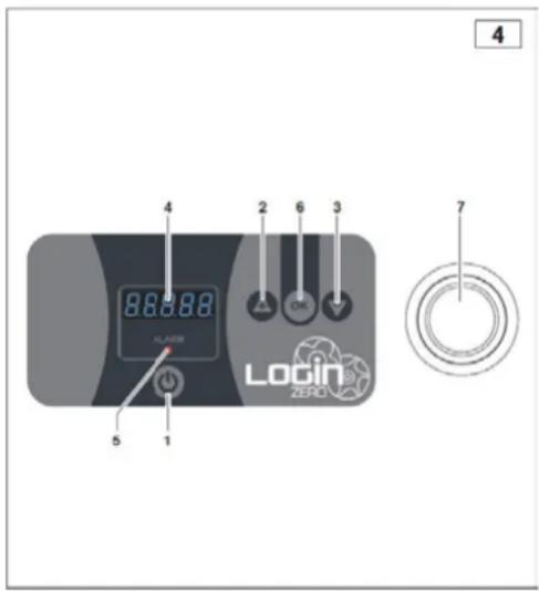
CONTROL PANEL
This version is equipped with an electronic controller which manages all compressor functions (Fig. 4):
- START key: Controls the start-up of the compressor.
- UP ARROW key/PLUS key:
UP ARROW: Scrolls the menu items up.
PLUS key: Increases the value of the parameter during editing.
- DOWN ARROW key/MINUS key:
DOWN ARROW: Scrolls the menu items down.
MINUS key: Decreases the value of the parameter during editing.
- Display: Shows information.
- Alarm warning lights: Light up in case of an alarm.
- OK key: Allows access to the displayed menu. Allows confirming the value during the parameter editing.
- Emergency shutdown button: Causes the compressor to stop immediately. Use it only in case of real need.
GENERAL DESCRIPTION OF OPERATION
The control panel directly controls all parameters and sensor indications to operate the screw compressor through start and stop cycles.
OPERATION
If there are no alarms after start-up, the display shows a shade alternating with the status of the compressor. The + or - keys can be pressed to change the display according to the Display Table. When the keys are not used for 20 seconds, the display reverts to display no. 1.
Display Table:
| 1. Compressor status alternates with pressure for 1.5 seconds | ||
| - | On | Compressor is ON |
| - | C on | Compressor is ON + charge solenoid valve is active |
| - | Off | Compressor is OFF |
| - | StaBy | Compressor is in standby mode |
| - | Time | Compressor is waiting for standby mode |
| Pressure | ||
| - | P.10.8 | For bar P10.8 |
| - | P.156 | For Psi P156 |
| 2. Temperature | ||
| - | 090C | for °C |
| - | 123F | for °F |
| 3. | OL. - 0012 | OL. and line hours flash |
| 4. | OC. - 00007 | OC. and load hours flash |
| 5. | OM. - 01000 | OM. and service hours flash |
| 6. | Ci. - 00254 | Ci and motor start cycles flash |
Start-up procedure:
Press the ON/OFF KEY to perform the compressor start cycle.
1) Waiting for start-up: The display shows TIME and waits for 20 seconds to elapse since the last motor shutdown.
2) Compressor start-up: The display shows ON and the motor starts.
3) Compressor loading phase: The display shows C ON, and the solenoid valve relay is energized. This phase lasts until the pressure set by the "01 Offload pressure" parameter is reached.
4) Stand-by phase: The "01 Offload pressure" parameter is reached, the display shows STA.BY, the solenoid valve relay is de-energized and the motor stops. If the pressure has fallen below the "02 Loading pressure" parameter, the cycle resumes from step 2; otherwise, the compressor remains in stand-by.
Shutdown procedure:
Press the ON/OFF key to start the shutdown procedure. The loading solenoid valve is de-energized. The control unit enters shutdown and the display shows OFF.
PARAMETERS MENU:
Reading and programming parameters
When the compressor is stopped, press the OK key for 3 seconds. The display will show PASS. Press the OK key to access the user parameters.
After accessing the menu, the parameter number will flash (e.g. Par. 01). The + and - keys can be used to scroll through the parameters. Pressing OK displays the parameter value. Use the + or - keys to adjust the value, then press OK to confirm. MEM will be displayed to confirm that the parameter is saved. Each parameter has its maximum and minimum values, along with a unit of measurement, as shown in the parameter table. Press the ON/OFF key to exit the user parameters.
Table of parameters that can be programmed:
| Parameter no. | Description | Default | min | max | Unit of measure |
| User menu | |||||
| 01 | Offload pressure | 10 | 0.5 | 16 | bar |
| 02 | Loading pressure | 8.5 | 0.5 | 16 | bar |
| 03 | Bar/PSI pressure unit of measure | 1 | 1 | 2 | |
| 04 | Temperature unit of measure (1 = °C or 2 = °F) | 1 | 1 | 2 |
USER MENU:
01 Offload pressure: Sets the pressure at which the compressor must stop. The maximum value that can be set is defined by the "Maximum value to be set" parameter in the factory menu.
02 Loading pressure: Sets the residual pressure required to restart the compressor. The maximum value that can be set is locked to 0.5 bar less than the value set by the "Offload pressure" parameter.
03 Bar/PSI unit of measure: Sets the pressure unit of measure.
04 Temperature unit of measure: Sets the temperature unit of measure (1 = °C or 2 = °F).
7. ALARMS
ALARMS AND MAINTENANCE
- During operation, alarms may occur, which are shown on the display and by means of the red ALARM LED.
- The ALARM LED remains active only if there are alarms.
• The alarms shown on the display can be reset if no longer active, by briefly pressing the OK key.
Alarm list:
| Alarms that stop the machine | |
| ALL.00 | Emergency input |
| ALL.01 | Motor PTC |
| ALL.02 | Fan thermal breaker |
| ALL.03 | Maximum temperature |
| ALL.04 | Minimum temperature |
| ALL.05 | Temperature sensor faulty |
| ALL.06 | Pressure sensor faulty |
| ALL.07 | Wrong rotation direction or phase absent |
| ALL.08 | Maximum pressure |
| Alarms that do not stop the machine | |
| ALL.10 | Oil temperature pre-alarm |
| ALL.11 | Maintenance |
8. OPERATION
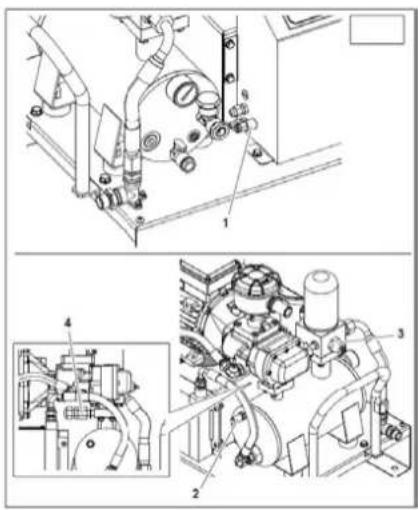
SAFETY AND CONTROL DEVICES (Fig. 5)
1) Pressure transducer: Regulates STOP and START pressure.
2) Safety valve: Opens the air vent to the safety value.
3) Minimum pressure valve: Prevents leakage of compressed air if the pressure is below the calibration value of the valve.
4) Maximum temperature probe: Shuts down motor when 110^ C is exceeded.
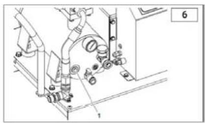
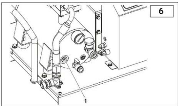
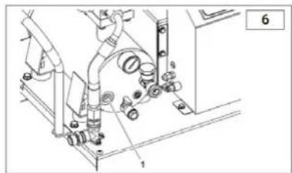
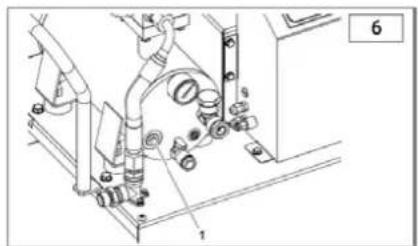
HEATER ELEMENT (OPTIONAL KIT) (Fig. 6)
Recommended for machines with non-continuous operating cycles.
The heater element immersed in the oil of the oil trap tank (Fig. 6) keeps it hot and prevents excessive condensation.
When installed, the operation is automatically controlled by the electronic control unit. The heater element is powered only during the standby stage under specific conditions.
natural_image
Technical line drawing of a mechanical assembly with pipes and components (no text or symbols)OPERATING CYCLE (Fig. 7)
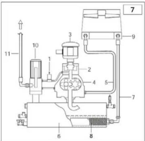
1) At start-up, the motor starts directly; it reaches standard speed after 5-7 seconds.
2) The solenoid valve (1) receives current and closes. The suction regulator (2) opens and takes in atmospheric air through the filter (3).
3) At this stage, the compressor runs at full speed and begins to compress the air in the tank (6).
4) The compressed air cannot come out from the minimum pressure valve set at 3÷4 bar.
5) The compressed air compresses the oil in the tank (6) and forces it to flow through the filter (8) and pipe (7) to the radiator (9).
6) If the oil temperature is below 75^ C, the electric fan remains still.
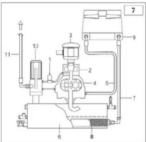
7) If the oil temperature exceeds 75^ C, the fan starts operating, and cooled oil returns to the compressor thro
8) The oil reaches the compressor (4), mixing with the intake air and creating an air/oil mixture which ensures the seal and the lubrication of the moving parts of the compressor.
9) The air/oil mixture returns to the tank (6), where the air is pre-separated. A final separation of the oil takes place through the oil separator filter (10), and the oil is conveyed to the distribution network.
10) Upon standby or shutdown, the motor stops, the solenoid valve (1) is no longer powered, and it opens, allowing the oil separator tank (6) to be depressurised.
9. MAINTENANCE
• Proper maintenance is crucial for achieving maximum efficiency and extending the operational life of your compressor.
- It is important to follow the recommended maintenance intervals, but keep in mind that these intervals are based on the assumption that the compressor operates under optimal environmental conditions (see the “Installation” chapter).
- The maintenance intervals may therefore need to be shortened if the compressor operates in less than optimal environmental conditions.
- The recommended oil is FSN Original Oil. Using a different type of oil may not guarantee the same efficiency or compliance with the maintenance intervals.
- The maintenance tasks described in the table below and throughout the following pages must be performed by authorized personnel only.
Maintenance table
| Type of maintenance | Maintenance schedule | |
| work hours | or at least | |
| Drain condensate from air tank (if present) | 50 | weekly |
| Drain condensate from the oil separator tank | 50 | weekly |
| Oil check and top up if necessary | 500 | once a month |
| Check radiator for clogging and clean it 500 | 500 | once a month |
| Replace air filter | after first 500/every 1000 | once a year |
| Replace oil filter | after first 500/every 1000 | once a year |
| Change oil | after first 500/every 1000 | once a year |
| Change oil separator filter | 4000 | every two years |
| Replace drain one-way valve | 4000 | every two years |
| Overhaul intake valve | 4000 | |
| Overhaul minimum pressure valve | 8000 | |
| Replace solenoid valve | 8000 | |
| Replace hoses | 8000 | |
| Overhaul and/or replace screw unit | 16000 | |
| Refer to the motor manual and/or to the motor data plate for electric motor bearing maintenance. | ||
Perform the following checks after the first 100 hours of operation:
1) Check the oil level and top up with the same type of oil if necessary.
2) Check for proper screw tightening, in particular the power electric connection screws.
3) Visually inspect that all fittings are properly sealed.
4) Verify the room temperature.
BEFORE PERFORMING MAINTENANCE, ALWAYS DO THE FOLLOWING:
√ Press the machine automatic stop button (do not use the emergency button).
√ Switch off the power via the external switch on the wall.
√ Close the line cock.
√ Ensure no compressed air remains in the oil separator tank.
√ Remove covers and/or panels.
CONDENSATION DRAIN
The oil/air mixture cooling is set to a higher temperature that the dew point of the air (under standard operating conditions of the compressor). However, the condensate in the oil cannot be fully removed.
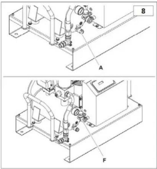
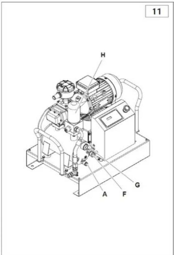
The drain the condensation, open cock A and close it once the oil starts flowing out instead of water. Check the oil level and top up if necessary.
CONDENSATE IS A POLLUTING MIXTURE!
It must not be disposed of in the sewers.
OIL CHECK AND TOP UP IN CASE OF NEED
Check the oil level by means of indicator on the left side of the oil separator tank. If the level is below the maximum, top up through the port F. For the quantity of oil required to top up from the minimum to the maximum level, see the technical data table.
CLEANING / REPLACEMENT OF AIR FILTER
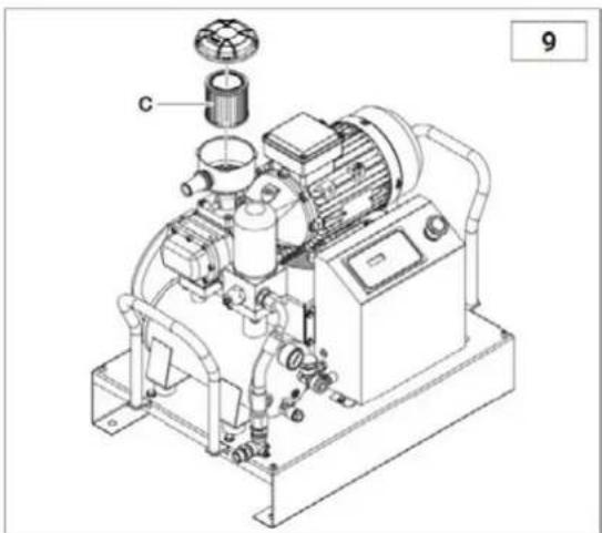
Clean the air filter C by blowing compressed air from the inside to the outside. Inspect the filter for any cuts by checking it against the light. If any damage is found, replace the filter. When reassembling, make sure the filter cartridge and cover are installed carefully to prevent dust from entering the compression unit.
natural_image
Technical line drawing of an industrial pump system with labeled component 'c' (no text or symbols beyond label)CLEANING THE RADIATOR
Clean the radiator if the temperature exceeds recommended levels or at least once a year. Here's how:
- Remove the radiator unit and spray it (with a spray gun + solvent) from the outside to the inside.
- Ensure proper air flow through the radiator.
OIL FILTER CHANGE
The oil filter D must be replaced when the tank is not under pressure and is free of oil.
Before refitting it manually, always apply some oil to the O-ring seal of the filter.
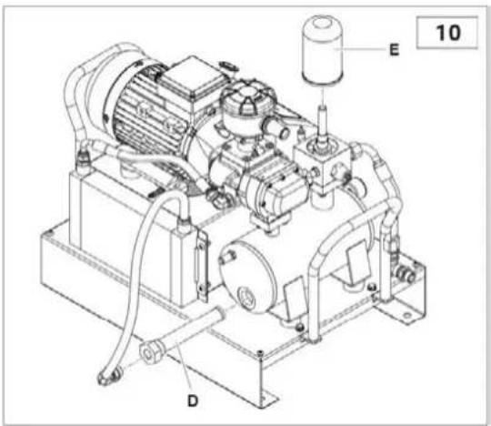
OIL SEPARATOR FILTER CHANGE
The oil separator filter E cannot be cleaned but must be replaced. Follow these steps:
- Unscrew filter manually (or if necessary, use an appropriate filter tool) turning it anticlockwise.
- Slightly grease the oil separator filter seal and O-ring before fitting the new filter by turning it counterclockwise.
WARNING: The replacements must be performed simultaneously with the oil change.
OIL CHANGE
When the compressor temperature exceeds 70^ C, change the oil as follows:
- Insert the supplied hose onto cock A.
- Remove the used oil separator filter H.
- Open cock A and let the oil flow into a collection tray until completely drained. Close the cock and remove the pipe.
- Remove cap G and pour new oil from port F (refer to the technical data table for the quantity needed for complete refilling).
- Close cap G.
• Install the new oil separator filter H.
• Power on the machine.
- Start the machine and wait for 5 minutes, then stop it.
- Vent all air.
- Wait for 5 minutes and check the oil level. Top up if necessary. SPENT OIL CAN POLLUTE THE ENVIRONMENT! Dispose of it in accordance with current environmental protection laws.
- The oil used for the first time is FSN Original Oil. The following types are included:
| Description | Type of oil |
| RotEnergyPlus 46cST | Synthetic lubricant ISO 46 for industrial use. |
| RotEnergyFood 46cST | Synthetic lubricant ISO 46 for foodstuff use. |
| RotarECOFLUID 46cST | Mineral lubricant ISO 46 for industrial use. |
A label attached to the compressor tank indicates the exact type of oil used before the first installation. It is recommended to use this type of oil for all future oil changes as per the scheduled maintenance intervals (refer to the maintenance table).
- TROUBLESHOOTING
| Issue | Cause | Solution |
| Motor stopped (thermal relay operation signal). | Voltage too low. | Check voltage, press Reset and then restart. |
| Overtemperature. | Check motor absorption and relay setting. In case of regular absorption, press Reset and restart. | |
| Overtemperature of the electric fan motor. | Check the fan motor and its overload switch. | |
| High oil consumption. | Faulty drainage. | Check oil drain hose and check valve. |
| Oil level too high. | Check oil level and drain some if necessary. | |
| Oil separator filter broken. | Replace oil separator filter. | |
| Oil separator filter seal leaking. | Replace oil separator nipple seals. | |
| Intake filter leaks oil. | Suction regulator stays open. | Check regulator and solenoid valve. |
| Safety valve opening. | Pressure too high. | Check service pressure switch setting. |
| Suction regulator does not close at the end of the cycle. | Check regulator and solenoid valve. | |
| Oil separator filter clogged. | Replace oil separator filter. | |
| Sensor for compressor temperature triggered. | Room temperature too high. | Increase ventilation. |
| Radiator clogged. | Clean radiator with solvent. | |
| Oil level too low. | Top up oil. | |
| Electric fan does not start. | Check the fan motor and its overload switch. | |
| Poor compressor performance. | Air filter dirty or clogged. | Clean or replace the filter. |
| Compressor does not compress air while running. | Regulator closed. It cannot open because it is dirty. | Remove intake filter and check for proper manual opening. Remove and clean, if necessary. |
| Compressor compresses air beyond max. pressure value. | Regulator open. It cannot close because it is dirty. | Remove and clean regulator. |
| Compressor does not start. | Oil separator filter clogged. | Replace oil separator filter. |
| Min. pressure valve does not close perfectly. | Remove the valve, clean, and replace seal, if necessary. | |
| Compressor hard to start. | Voltage too low. | Check mains voltage. |
| Pipes leaking. | Tighten fittings. |
11. WIRING DIAGRAM
11.1 Single-phase Version:
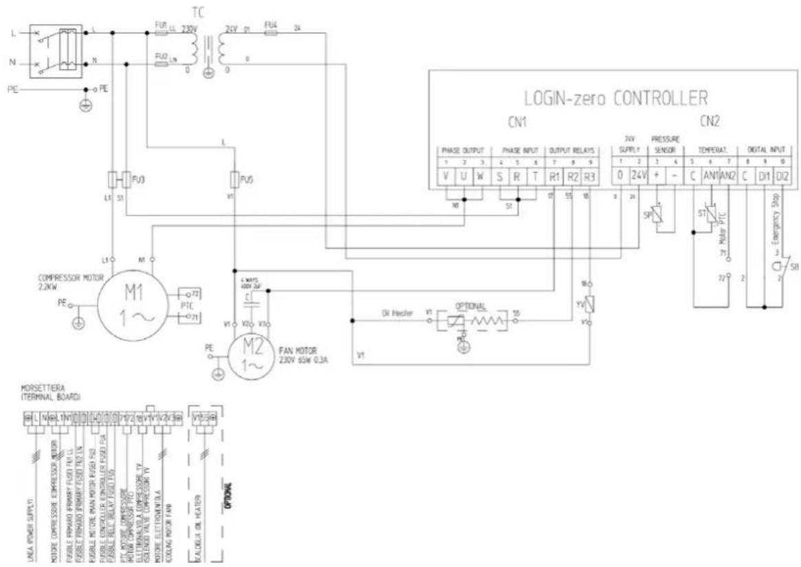
| Ref. | Denomination | 2.2 KW |
| TC | TRANSFORMER 80 VA 230 V-0 VSec. 24 V-0 V | |
| ST | TEMPERATURE PROBE | |
| BP | PRESSURE SENSOR | |
| SB | EMERGENCY BUTTON + no.2NC 230 V 10 A | |
| FU1-FU2 | Transformer CERAMIC FUSES | 1 A |
| FU3 | 2x CERAMIC FUSE 230 V Motor | 16 A |
| FU4 | Secondary CERAMIC FUSE 24 V | 1 A |
| FU5 | CERAMIC FUSE 230 V relay | 2 A |
11.2 Three-phase Version:
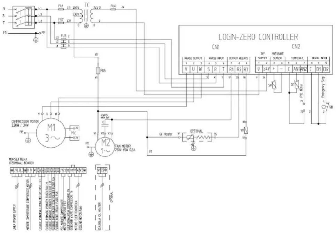
| Ref. | Denomination | 2.2 KW | 3 KW |
| TC | TRANSFORMER 80 VA 400 V-0 VSec. 24 V-0 V | ||
| ST | TEMPERATURE PROBE | ||
| BP | PRESSURE SENSOR | ||
| SB | EMERGENCY BUTTON + no.2NC 230 V 10 A | ||
| FU1-FU2 | Transformer CERAMIC FUSES | 1 A | 1 A |
| FU3 | 2x CERAMIC FUSE 400 V Motor | 10 A | 12 A |
| FU4 | Secondary CERAMIC FUSE 24 V | 1 A | 1 A |
| FU5 | CERAMIC FUSE 230 V relay | 2 A | 2 A |
1.
INFORMACJE OGÓLNE
DEKLARACJA ZGODNOŚCI
natural_image
Technical line drawing of a mechanical housing or enclosure with dimension annotations (465 and 618), no readable text or symbols present.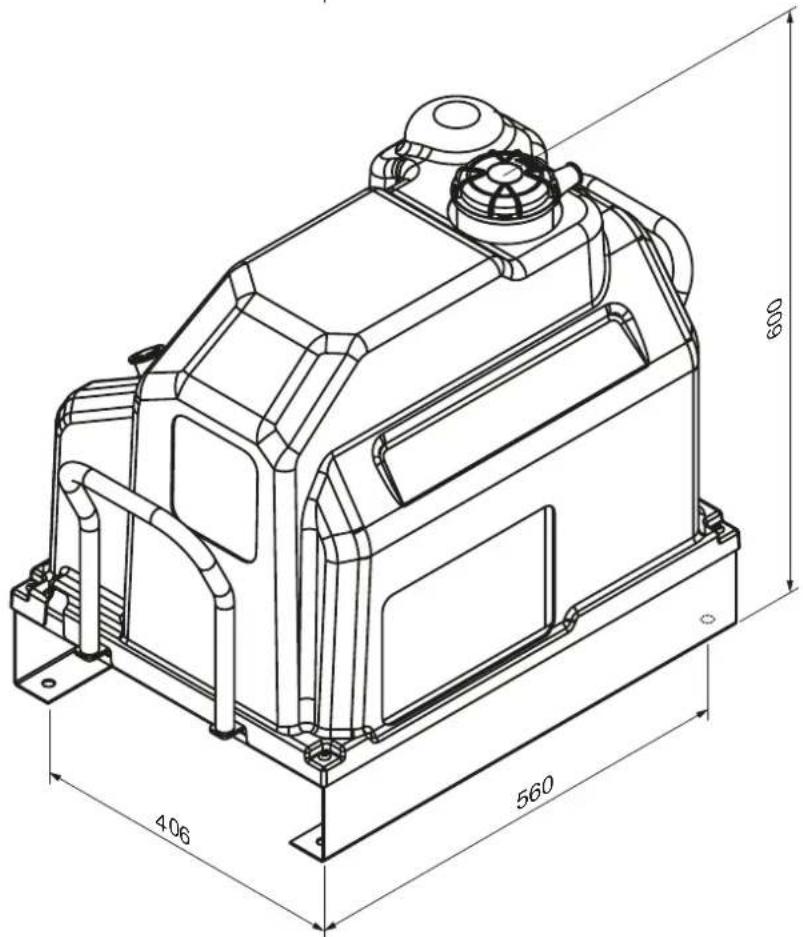
2.2.
WYMIARY GABARYTOWE
3.1.
ZASADY BEZPIECZEŃSTWA
UWAGI OGÓLNE ODNOŚNIE BEZPIECZEŃSTWA
DESCRIPTION OF THE COMPRESSOR (fig. 1-1a)
The compressor essentially consists of the following:
- Electrical equipment
- Electronic controller
- Oil radiator
- Air filter
- Suction regulator
- Screw compressor
-
Oil separator tank
-
Oil filter
- Oil separator filter
- Minimum pressure valve
- Electric motor
- Casing
- 90l tank
5.
MONTAŻ
ROZPAKOWANIE I MONTAŻ MASZYNY
ALARMY I KONSERWACJA
natural_image
Technical line drawing of a mechanical assembly with pipes, valves, and components (no text or symbols)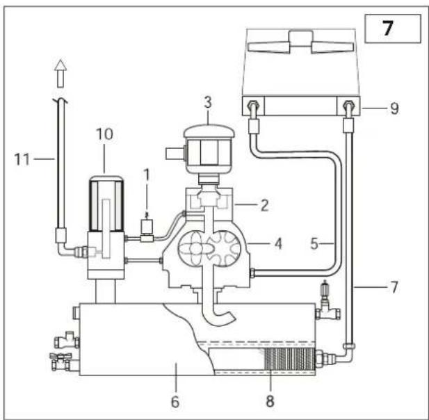
SERWISOWANIE10.1.
natural_image
Technical line drawing of an industrial pump system with labeled component 'c' (no text or symbols beyond label)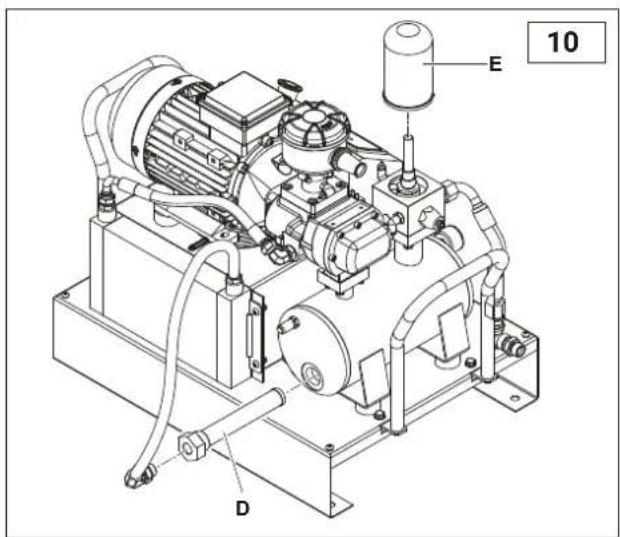
SERWISOWANIE10.3.
WYMIANA OLEJU
- ROZWIĄZYWANIE PROBLEMÓW
natural_image
Technical line drawing of a mechanical device with dimension annotations (465 and 618), no readable text or symbols beyond measurement lines.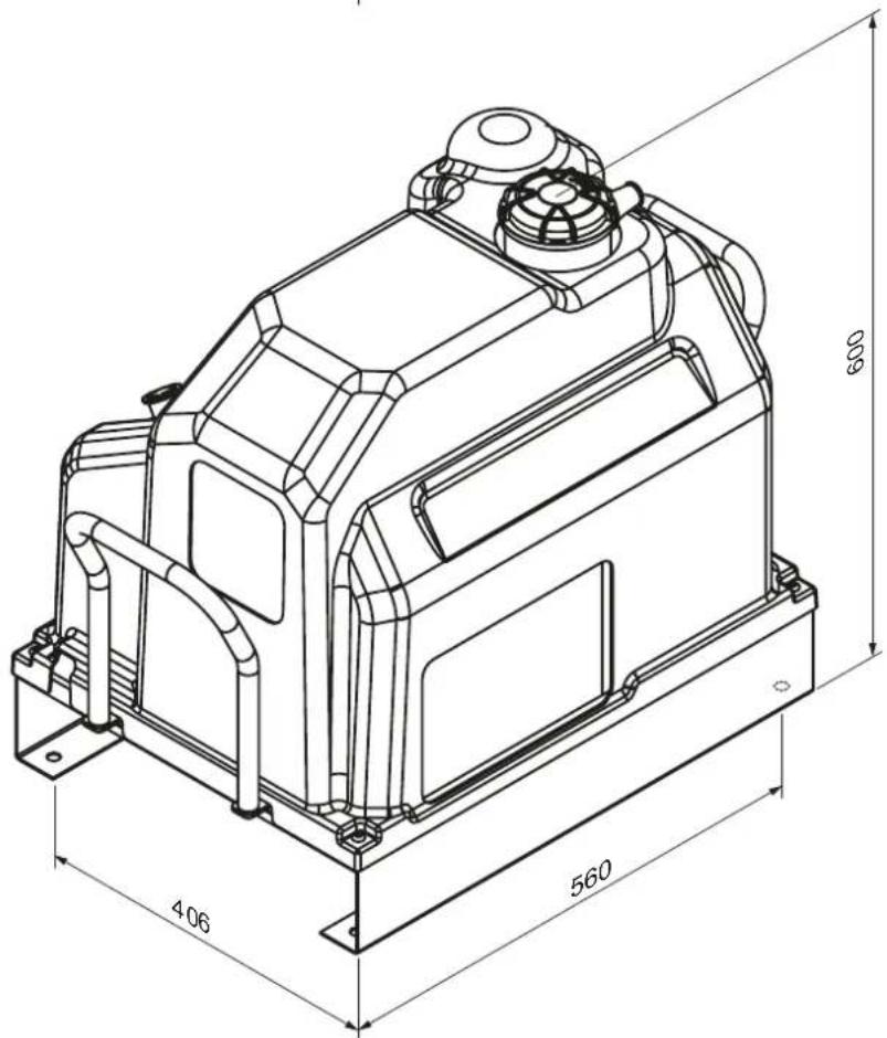
natural_image
Technical line drawing of a mechanical assembly with pipes and components (no text or symbols)BETRIEBSZYKLUS (Abb.6)
natural_image
Technical line drawing of an industrial machine with labeled components (no text or symbols present)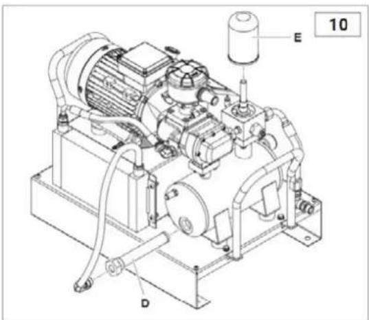
natural_image
Technical line drawing of a mechanical device with dimension annotations (465 and 618), no readable text or symbols beyond measurement lines.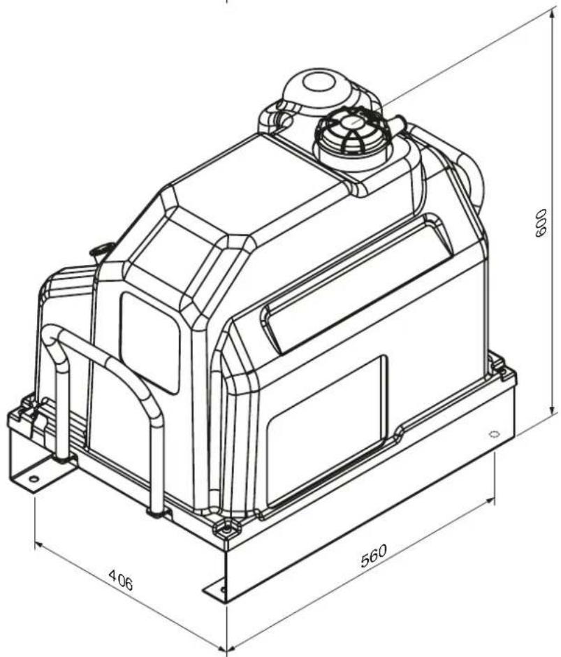
3. VEILIGHEIDSVOORSCHRIFTEN
ALGEMENE WAARSCHUWINGEN
WAT JE NIET MOET DOEN:
BESCHRIJVING VAN DE COMPRESSOR (Afb. 1-1a)
VERWARMINGSELEMENT (OPTIONEEL KIT) (afb.6)
natural_image
Technical line drawing of a mechanical assembly with pipes and components (no text or symbols)WERKCYCLUS (afb.6)
natural_image
Technical line drawing of an industrial pump system with labeled components (no text or symbols beyond labels)OLIEFILTER VERVANGEN
DÉCLARATION DE CONFORMITÉ
natural_image
Technical line drawing of a mechanical device with dimension annotations (465 and 618), no readable text or symbols beyond measurement lines.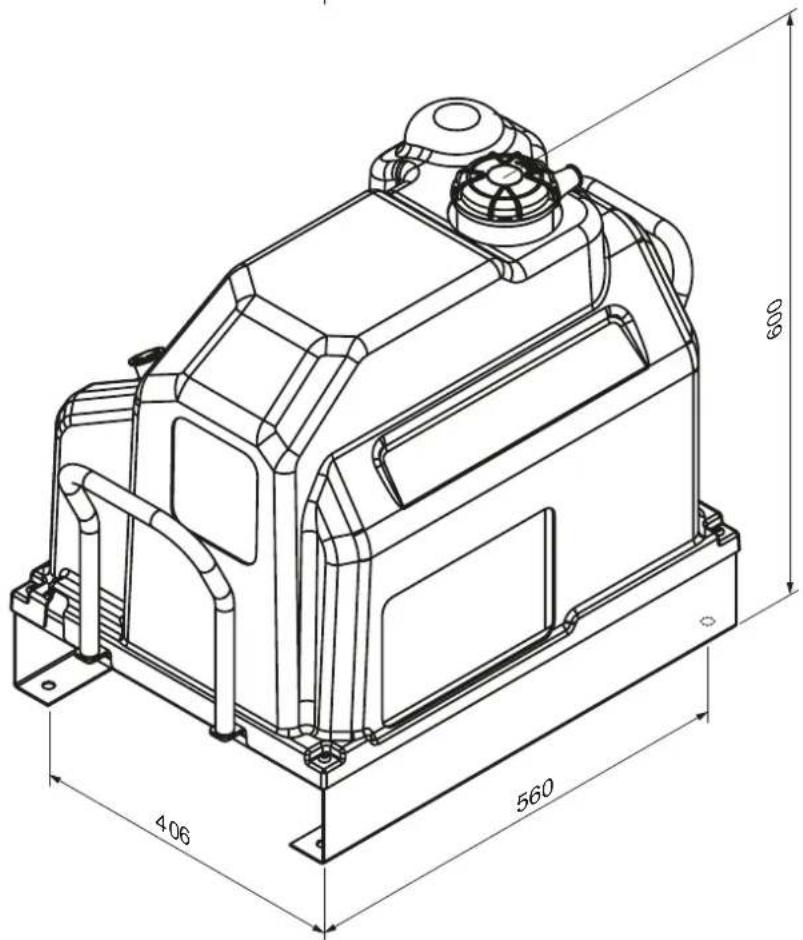
3. RÈGLES DE SÉCURITÉ
AVERTISSEMENTS GÉNÉRAUX
DESCRIPTION DU COMPRESSEUR (fig. 1-1a)
RACCORDEMENT ÉLECTRIQUE (fig. 3)
natural_image
Technical line drawing of a mechanical assembly with labeled parts (no readable text or symbols)ÉLÉMENT CHAUFFANT (KIT OPTIONNEL) (fig. 6)
9. ENTRETIEN
natural_image
Technical line drawing of an industrial pump system with labeled component 'C' (no text or symbols beyond label)REEMPLACEMENT DU FILTRE À HUILE
natural_image
Technical line drawing of a mechanical device with dimension annotations (465 and 618), no readable text or symbols beyond measurement lines.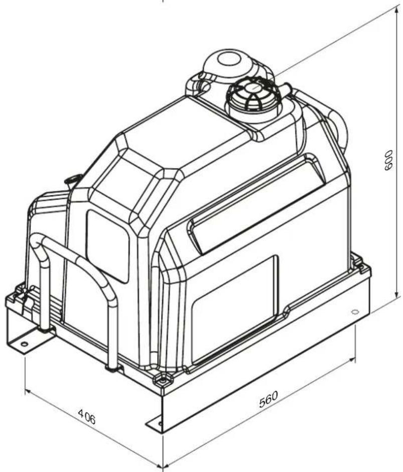
3. BIZTONSÁGI ELŐÍRÁSOK
ÁLTALÁNOS FIGYELMEZTETÉSEK
FÜTÖELEM (OPCIONÁLIS KÉSZLET) (6. ábra)
natural_image
Technical line drawing of a mechanical assembly with no visible text or symbolsMÜKÖDÉSI CIKLUS (7. ábra)
9. KARBANTARTÁS
natural_image
Technical line drawing of an industrial pump system with labeled component 'c' (no text or symbols beyond label)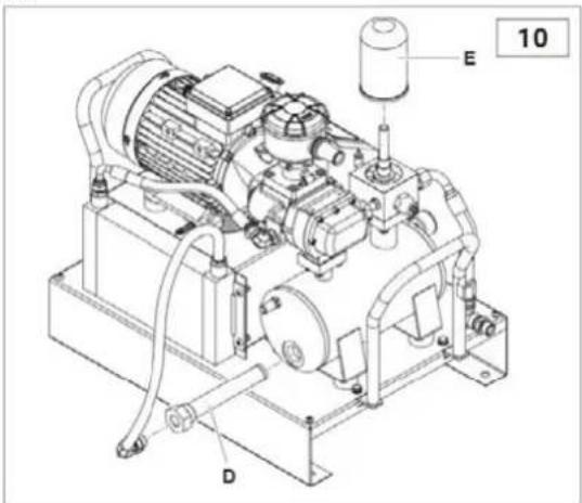
natural_image
Technical line drawing of a mechanical device with dimension annotations (465 and 618), no readable text or symbols beyond measurement lines.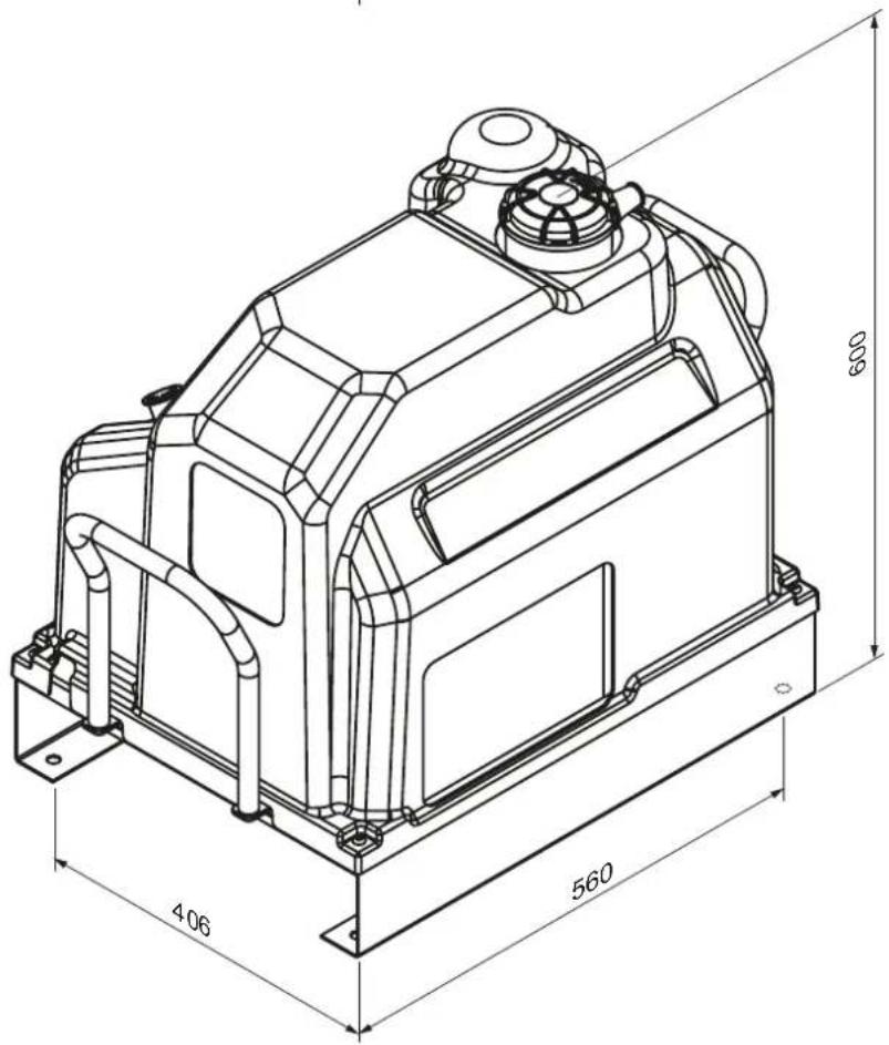
3. NORME DE SIGURANTĂ
AVERTISMENTE GENERALE
DESCRIEREA COMPRESORULUI (Fig. 1-1a)
ELEMENT DE ÎNCĂLZIRE (KIT OPTIONAL) (Fig. 6)
natural_image
Technical line drawing of a mechanical assembly with pipes and components (no visible text or symbols)CICLUL DE FUNCTIONARE (Fig. 7)
ÎNTRETINERE
CURĂȚAREA / ÎNLOCUIREA FILTRULUI DE AER
natural_image
Technical line drawing of an industrial pump or motor assembly with labeled components (no text or symbols present)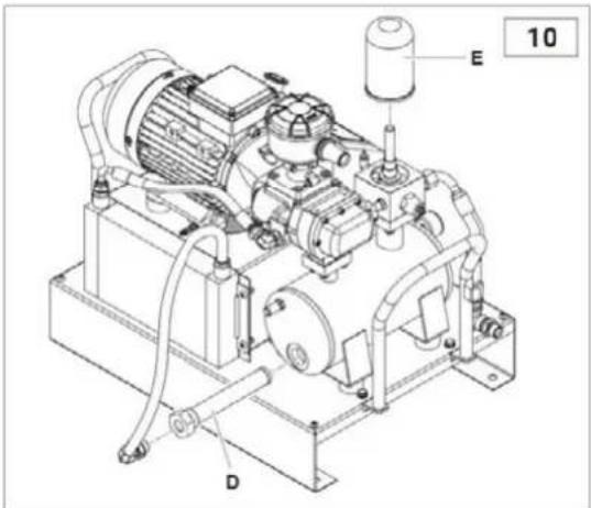
| Ref. | Denominatie | 2.2 KW |
| TC | TRANSFORMATOR 80 VA 230 V-0 VSec. 24 V-0 V | |
| ST | SONDĂ DE TEMPERATURĂ | |
| BP | SENZOR DE PRESIUNE | |
| SB | BUTON DE URGENTĂ + nr.2NC 230 V 10 A | |
| FU1-FU2 | Transformer FUSIBILE CERAMICE | 1 A |
| FU3 | 2x FUSE CERAMIC 230 V Motor | 16 A |
| FU4 | Siguranță secundară CERAMIC FUSE 24 V | 1 A |
| FU5 | FUSIBIL CERAMIC 230 V releu | 2 A |
natural_image
Technical line drawing of a mechanical device with dimension annotations (465 and 618), no readable text or symbols beyond measurement lines.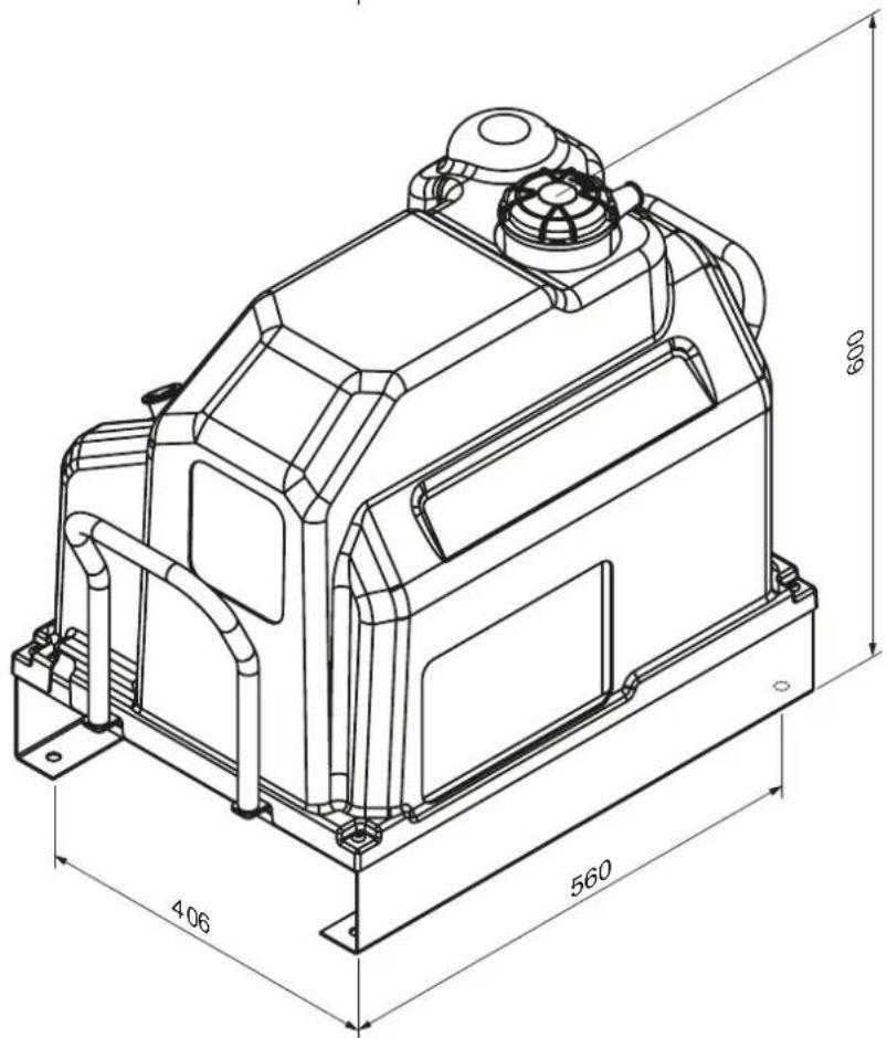
3. BEZPEČNOSTNÉ PREDPISY
VŠEOBECNÉ UPOZORNENIA
POPIS KOMPRESORA (obr. 1-1a)
Kondenzát by sa mal zhromažďovat' v šachte alebo nádrži.
Vykurovací prvok (VOLITEL'NÁ SADA) (obr. 6)
natural_image
Technical line drawing of a mechanical assembly with no visible text or symbolsPRACOVNÝ CYKLUS (obr. 7)
KONDENZÁT JE ZNEČISTUJÚCA ZMES!
ČISTENIE / VÝMENA VZDUCHOVÉHO FILTRA
natural_image
Technical line drawing of an industrial pump system with labeled component 'c' (no text or symbols beyond label)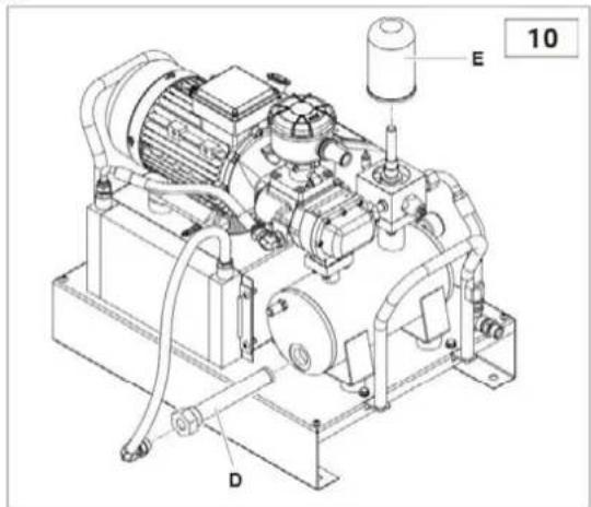
natural_image
Technical line drawing of a mechanical device with dimension annotations (465 and 618), no readable text or symbols beyond measurement lines.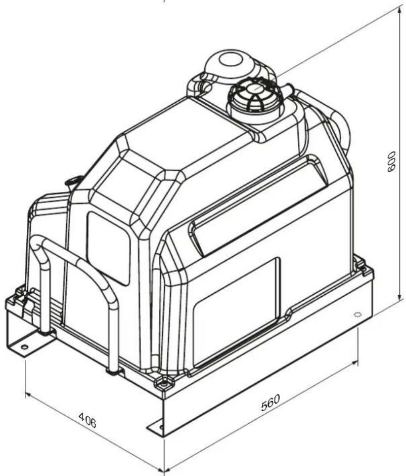
3. VARNOSTNI PREDPISI
SPLOŠNA OPOZORILA
OPIS KOMPRESORJA (slika 1-1a)
ELEKTRIČNA PRIKLJUČITEV (slika 3)
OGREVALNI ELEMENT (izbirni komplet) (slika 6)
9. VZDRŽEVANJE
natural_image
Technical line drawing of an industrial pump system with labeled components (no text or symbols present)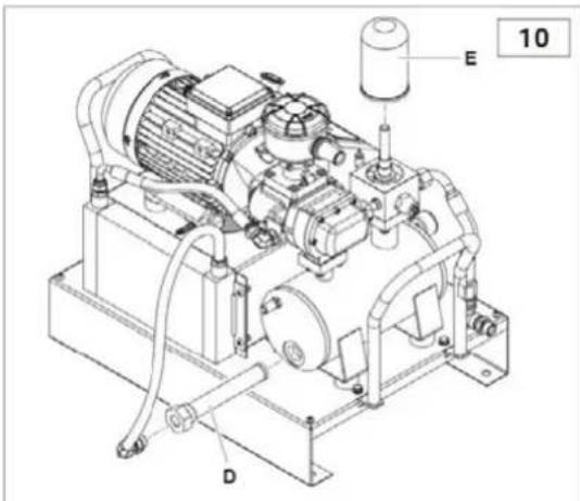
| Ref. | Naziv | 2,2 KW | 3 KW |
| TC | TRANSFORMATOR 80 VA 400 V-0 V Oddelek 24 V-0 V | ||
| ST | TEMPERATURNA SONDA | ||
| BP | SENZOR TLAKA | ||
| SB | Gumb za nujne primere + št. 2 NC 230 V 10 A | ||
| FU1-FU2 | Transformatorske keramične varovalke | 1 A | 1 A |
| FU3 | 2x keramična varovalka 400 V za motor | 10 A | 12 A |
| FU4 | Sekundarna keramična varovalka 24 V | 1 A | 1 A |
| FU5 | Keramična varovalka 230 V rele | 2 A | 2 A |
ATBILSTĪBAS DEKLARĀCIJA
natural_image
Technical line drawing of a mechanical device with dimension annotations (465 and 618), no readable text or symbols beyond measurement lines.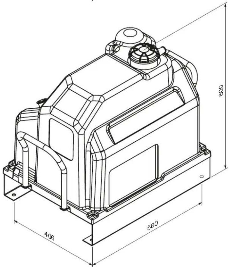
3. DROŠĪBAS NOTEIKUMI
VISPĀRĪGI BRĪDINĀJUMI

KOMPRESSORA APRAKSTS (1-1a. attëls)
ELEKTRISKAIS SAVIENOJUMS (3. attëls)
natural_image
Technical line drawing of a mechanical assembly with no visible text or symbolsnatural_image
Technical line drawing of an industrial machine with labeled components (no text or symbols present)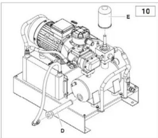
BRĪDINĀJUMS: Nomaina jāveic vienlaikus ar ellas mainu.
ELLAS NOMAINA
natural_image
Technical line drawing of a mechanical device with dimension annotations (465 and 618), no readable text or symbols beyond measurement lines.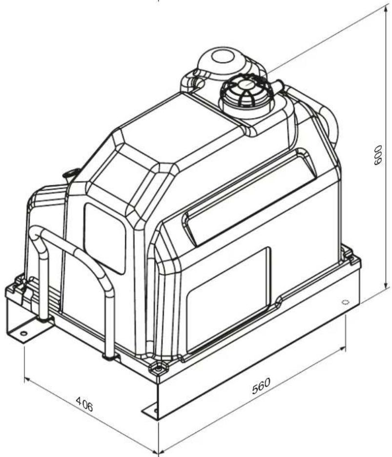
3. SAUGOS TAISYKLÈS
BENDRIEJI JSPÈJIMAI
KOMPRESORIAUS APRAŠYMAS (1-1a pav.)
ELEKTRINIS SUJUNGIMAS (3 pav.)
ŠILDYMO ELEMENTAS (PAPILDOMAS RINKINYS) (6 pav.)
natural_image
Technical line drawing of a mechanical assembly with pipes and components (no text or symbols)VEIKSMO CIKLAS (7 pav.)
natural_image
Technical line drawing of an industrial machine with pipes and housing (no text or symbols)ORO FILTRO VALYMAS / KEITIMAS
natural_image
Technical line drawing of an industrial pump or motor system with labeled components (no text or symbols present)ALYVOS FILTRO KEITIMAS
natural_image
Technical line drawing of a mechanical device with dimension annotations (465 and 618), no readable text or symbols beyond measurement lines.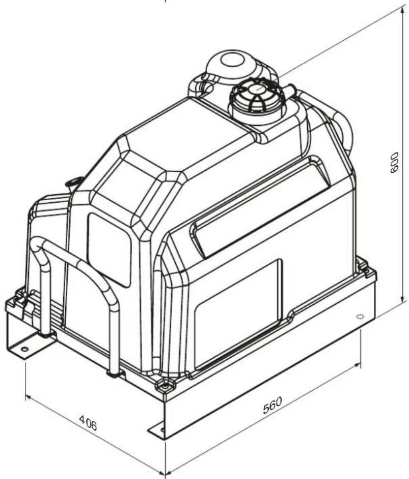

3. SIGURNOSNI PROPISI
OPĆA UPOZORENJA
OPIS KOMPRESORA (SI. 1-1a)
Kompresor se u osnovi sastoji od sljedećih komponenti:
- Električna oprema
- Filter ulja
- Elektronički regulator
- Filter za odvajanje ulja
- Hladnjak ulja
- Ventil minimalnog tlaka
- Filter za usis zraka
- Elektromotor
- Regulator usisavanja
- Stanovanje
- Modul vijaka
- Spremnik zraka od 90 litara
- Separator ulja
RASPAKIRAVANJE I SASTAVLJANJE
Prilikom isporuke, gornji dio kompresora je zaštićen kartonskom ambalažom.
ELEKTRIČNI PRIKLJUČAK (SI. 3)
- Provjerite da glavni kabel ima odgovarajući presjek za napajanje kompresora i da uključuje fazne žice br. 3 i uzemljenje br. 1.
- Ugradite osigurač ili magnetotermalni prekidač blizu ulazne točke kabela u stroj, između glavnog kabela i upravljačke ploče kompresora.
- Prekidač (A) treba biti lako dostupan operateru. Osigurajte da su korišteni kabeli odgovarajućeg tipa i da imaju odgovarajuću zaštitu (minimalna oznaka IP44).
BILJEŠKA: Za određivanje presjeka kabela, slijedite vodiče za dimenzioniranje kabela, temeljene na standardu VDE 0100 (dijelovi 430 i 523), osiguravajući prisutnost startera zvijezdatrokut, da je temperatura prostorije 30°C i da kabel ne prelazi 50 metara.
Ako je kompresor bio zaustavljen dulje od 30 dana, potrebno je ručno dodati ulje u zračni blok kako bi se osiguralo podmazivanje tijekom prvog pokretanja, kao što je opisano u„Vijčani kompresori - brzo pokretanje“Nepoštivanje ovog postupka može dovesti do blokiranja kompresorskog bloka. Za više informacija obratite se svom dobavljaču.
- TEHNIČKI PODACI
| Tehničke karakteristike Tip | 2,2milijuna | 2.2 | |||
| Radni tlak | bar g | 8 | 10 | 8 | 10 |
| Crpna jedinica | tip | FS 14 | |||
| Dovod zraka (ISO 1217, dodatak C) | L/min | 292 | 261 | 292 | 261 |
| Količina ulja | L | 2,3 | |||
| Količina ulja za dolijevanje | L | 0,3 | |||
| Maksimalna konačna previsoka temperatura zraka | °C | 3 | 3 | ||
| Uklonjena toplina | kJ/h | 7524 | 7524 | ||
| Protok ventilatora | m3/h | 600 | |||
| Ostaci ulja u zraku | mg/m3 | 2 - 4 | |||
| Električni motor | tip | 90 MC/2 | 90 MC/2 | ||
| Nazivna snaga | kW | 2,2 | 2,2 | ||
| Maksimalna ulazna snaga iz mreže, uključujući ventilaciju | kW | 2,7 | 3,1 | 2,7 | 3,1 |
| Ocjena zaštite električnog ormara | IP adresa | 54 | |||
| Ograničenje temperature okoline | °C | (+)2 – (+)45 | |||
| Zvučni tlak (prema Neuron/Cagi PN2CPTC2) | dB(A) | 65 | |||
| Električni podaci | |||||
| Napon napajanja | V / Ph / Hz | 230/1~/50 | 400/3~/50 | ||
| Pomoćni napon | V / Ph / Hz | 24/1~/50 | |||
| Maksimalna ulazna struja uključujući ventilaciju | A | 12,2 | 14,1 | 4,5 | 5,2 |
| Zaštita elektromotora, stupanj izolacije | IP adresa | 55/Ž | |||
| Faktor usluge | 1 | 1,15 | |||
| Zaštitni uređaji | |||||
| Maksimalna temperatura uljnog kruga | °C | 110 | |||
| Kalibracija predalarma uljnog kruga | °C | 105 | |||
| Kalibracija elektroničkog releja motora | A | PTC | PTC | ||
| Kalibracija sigurnosnog ventila | bar | 14 | |||
| Dimenzije i težina | |||||
| Duljina | mm | 618 (765 s ručkom) | |||
| Širina | mm | 465 | |||
| Visina | mm | 600 | |||
| Težina | kg | 68 | 68 | ||
| Izlaz zraka | G | 1/2" | |||
| Dimenzije i težina sa spremnikom od 90 litara | |||||
| Duljina | mm | 750 | |||
| Širina | mm | 465 | |||
| Visina | mm | 1144 | |||
| Težina | kg | 105 | 105 | ||
| Izlaz zraka | G | 1/2" | |||
6. KONTROLE I POSTAVKE
UPRAVLJAČKA PLOČA
Ova verzija je opremljena elektroničkim regulatorom koji upravlja svim funkcijama kompresora (slika 4):
- STARTtipka: Upravlja pokretanjem kompresora.
- STRELICA GOREtipka/tipka PLUS:
STRELICA GORE: Pomiče stavke izbornika prema gore.
OPĆI OPIS RADOVA
Upravljačka ploča izravno kontrolira sve parametre i indikacije senzora za rad vijčanog kompresora kroz cikluse pokretanja i zaustavljanja.
OPERACIJA
GRIJAČ (OPCIONALNI KOMPLET) (SI. 6)
natural_image
Technical line drawing of a mechanical assembly with pipes and components (no text or symbols)RADNI CIKLUS (SI. 7)
1) Prilikom pokretanja, motor se pokreće izravno; standardnu brzinu postiže nakon 5-7 sekundi.
2) Solenoidni ventil (1) prima struju i zatvara se. Regulator usisavanja (2) se otvara i usisava atmosferski zrak kroz filter (3).
3) U ovoj fazi, kompresor radi punom brzinom i počinje komprimirati zrak u spremniku (6).
4) Komprimirani zrak ne može izlaziti kroz ventil minimalnog tlaka postavljen na 3÷4 bara.
5) Komprimirani zrak komprimira ulje u spremniku (6) i prisiljava ga da teče kroz filter (8) i cijev (7) do hladnjaka (9).
6) Ako je temperatura ulja ispod 75°C, električni ventilator ostaje u mirovanju.
7) Ako temperatura ulja prijeđe 75°C, ventilator se uključuje, a ohlađeno ulje se kroz cijevi (5) vraća u kompresor.
natural_image
Technical line drawing of an industrial pump system with labeled component 'c' (no text or symbols beyond label)ČIŠĆENJE RADIJATORA
Očistite radijator ako temperatura prelazi preporučene razine ili barem jednom godišnje. Evo kako:
- Skinite hladnjak i poprskajte ga (pištoljem za prskanje + otapalom) izvana prema unutra.
- Osigurajte pravilan protok zraka kroz radijator.
IZMJENA FILTRA ULJA
Uljni filter D mora se zamijeniti kada spremnik nije pod tlakom i u njemu nema ulja.
natural_image
Technical line drawing of a mechanical device with dimension annotations (465 and 618), no readable text or symbols beyond measurement lines.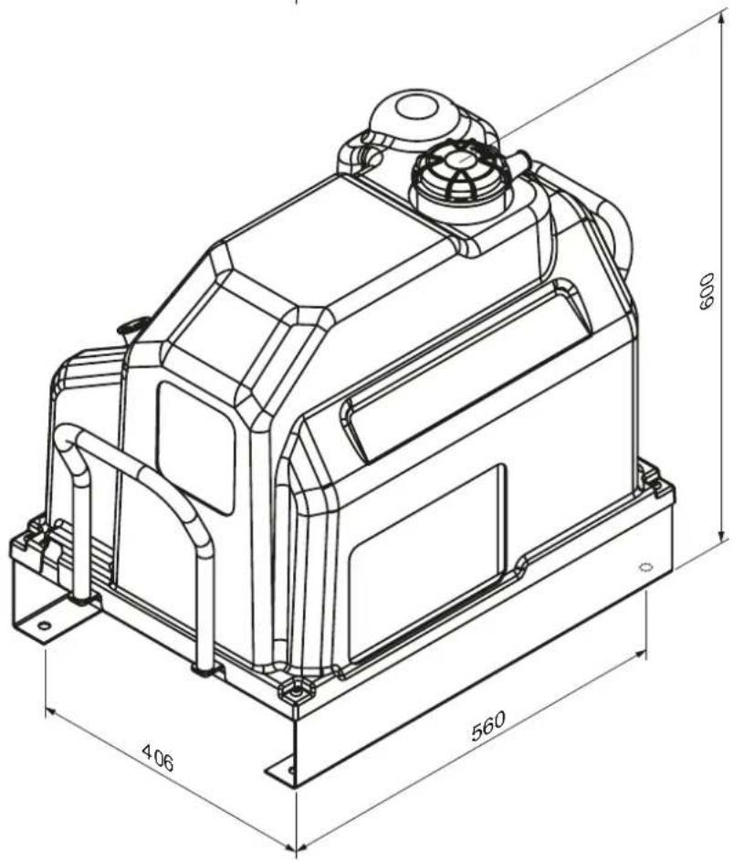
3. BEZPEČNOSTNÍ PŘEDPISY
OBECNÁ UPOZORNĚNÍ
POPIS KOMPRESORU (obr. 1-1a)
ELEKTRICKÉ PŘIPOJENÍ (obr. 3)
TOPNÝ ELEMENT (VOLITELNÁ SOUPRAVA) (obr. 6)
9. ÚDRŽBA
natural_image
Technical line drawing of an industrial pump system with labeled components (no text or symbols present)ČIŠTĚNÍ CHLADIČE
natural_image
Technical line drawing of a mechanical device with dimension annotations (465 and 618), no readable text or symbols beyond measurement lines.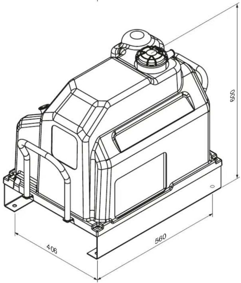
3. OHUTUSNÕUDED
ÜLDISED HOIATUSED
KOMPRESSORI KIRJELDUS (joonis 1-1a)
ELEKTRILISED ÜHENDUSED (joonis 3)
HÄIRESIGNAALID JA HOOLDUS
KÜTTEELEMENDI (VALIKLIK KIT) (joonis 6)
natural_image
Technical line drawing of a mechanical assembly with pipes and components (no text or symbols)TÖÖÖTSÜSTEEM (joonis 7)
natural_image
Technical line drawing of an industrial pump system with labeled component 'c' (no text or symbols beyond label)ÖLIFILTRI VAHETUS
natural_image
Technical line drawing of a mechanical device with dimension annotations (465 and 618), no readable text or symbols beyond measurement lines.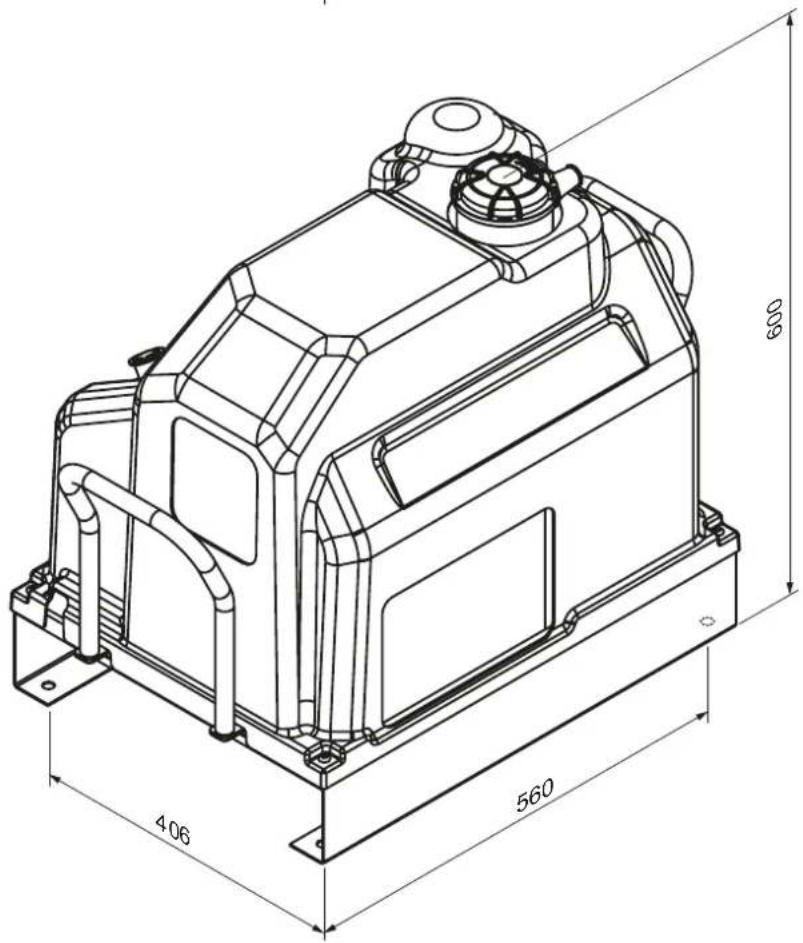
3. NORME DI SICUREZZA
AVVERTENZE GENERALI
DESCRIZIONE DEL COMPRESSORE (Fig. 1-1a)
natural_image
Technical line drawing of a mechanical assembly with pipes and components (no text or symbols)CICLO OPERATIVO (Fig. 7)
9. MANUTENZIONE
natural_image
Technical line drawing of an industrial pump system with labeled component 'c' (no text or symbols beyond label)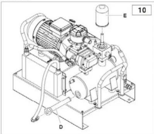
natural_image
Technical line drawing of a mechanical device with dimension annotations (465 and 618), no readable text or symbols beyond measurement lines.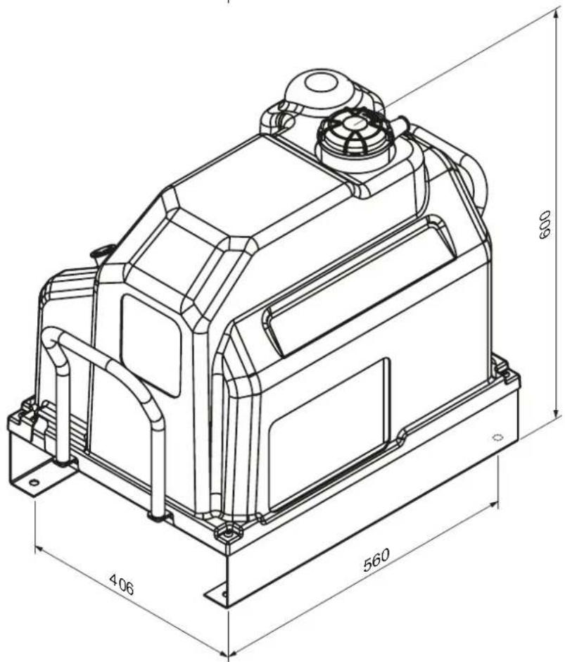
3. NORMAS DE SEGURANÇA
AVISOS GERAIS
DESCRIÇÃO DO COMPRESSOR (Fig. 1-1a)
ELEMENTO AQUECEDOR (KIT OPCIONAL) (fig.6)
natural_image
Technical line drawing of a mechanical assembly with pipes and components (no text or symbols)10. MANUTENÇÃO
natural_image
Technical line drawing of an industrial machine with pipes and control panel (no text or symbols)natural_image
Technical line drawing of an industrial pump system with labeled components (no text or symbols beyond labels)natural_image
Technical line drawing of a mechanical device with dimension annotations (465 and 618), no readable text or symbols beyond measurement lines.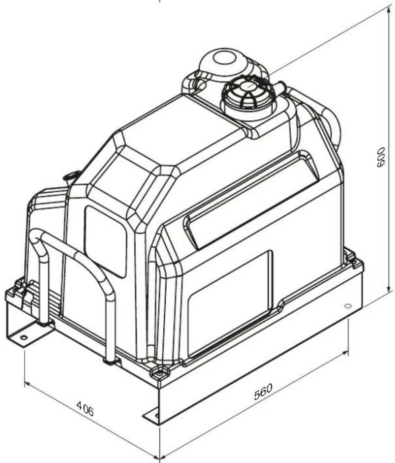
ELEMENTO CALEFACTOR (KIT OPCIONAL) (fig.6)
natural_image
Technical line drawing of a mechanical assembly with pipes and components (no text or symbols)10. MANTENIMIENTO
natural_image
Technical line drawing of an industrial pump system with labeled components (no text or symbols present)CAMBIAR EL FILTRO DE ACEITE
| Ref. | Denominación | 2,2 KW |
| TC | Transformador (TRANSFORMER) 80 VA 230 V-0 V Sec. 24 V-0 V | |
| ST | Sonda de temperatura (TEMPERATURE PROBE) | |
| BP | Sensor de presión (PRESSURE SENSOR) | |
| SB | Botón de emergencia (BOTÓN DE EMERGENCIA) + n° 2 NC 230 V 10 A | |
| FU1-FU2 | Fusible cerámico del transformador (FUSIBLES CERÁMICOS) | 1 A |
| FU3 | 2x Fusible cerámico 230 V Motor (FUSIBLE CERÁMICO) | 16 A |
| FU4 | Fusible secundario 24 V (FUSIBLE CERÁMICO) | 1 A |
| FU5 | Fusible cerámico 230 V relé (FUSIBLE CERÁMICO) | 2 A |
natural_image
Technical line drawing of a mechanical device with dimension annotations (465 and 618), no readable text or symbols beyond measurement lines.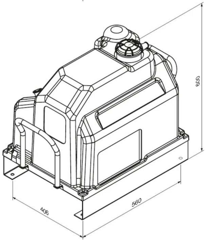
3. ПРАВИЛА БЕЗПЕКИ
natural_image
Technical line drawing of an industrial pump system with labeled components (no text or symbols beyond labels)ОЧИЩЕННЯ РАДІАТОРА
natural_image
Technical line drawing of a mechanical device with dimension annotations (465 and 618), no readable text or symbols beyond measurement lines.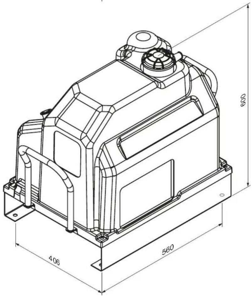
3. TURVALLISUUSMÄÄRÄYKSET
YLEISET VAROITUKSET
TOIMINNAN YLEINEN KUVAUS
LÄMMITINOSA (VALINNAINEN SARJA) (kuva 6)
natural_image
Technical line drawing of a mechanical assembly with pipes and components (no text or symbols)9. HUOLTO
ÖLJYN TARKASTUS JA TÄYDENNYS TARVITTAESSA
natural_image
Technical line drawing of an industrial pump system with labeled component 'c' (no text or symbols beyond label)JÄÄHDYTTIMEN PUHDISTAMINEN
| Ref. | Nimellisarvo | 2,2 KW |
| TC | MUUNTAJA 80 VA 230 V-0 V24 § V-0 V | |
| ST | LÄMPÖTILA-ANTURI | |
| BP | PAINEANTURI | |
| SB | HÄTÄNÄPPÄIN + nro 2NC 230 V 10 A | |
| FU1-FU2 | Muuntaja KERAAMISET SULAKKEET | 1 A |
| FU3 | 2x KERAMIIKKISULAKE 230 V moottori | 16 A |
| FU4 | Toissijainen KERAMIIKKISULAKE 24 V | 1 A |
| FU5 | KERAMIIKKISULAKE 230 V:n releet | 2 A |
natural_image
Technical line drawing of a mechanical device with dimension annotations (465 and 618), no readable text or symbols beyond measurement lines.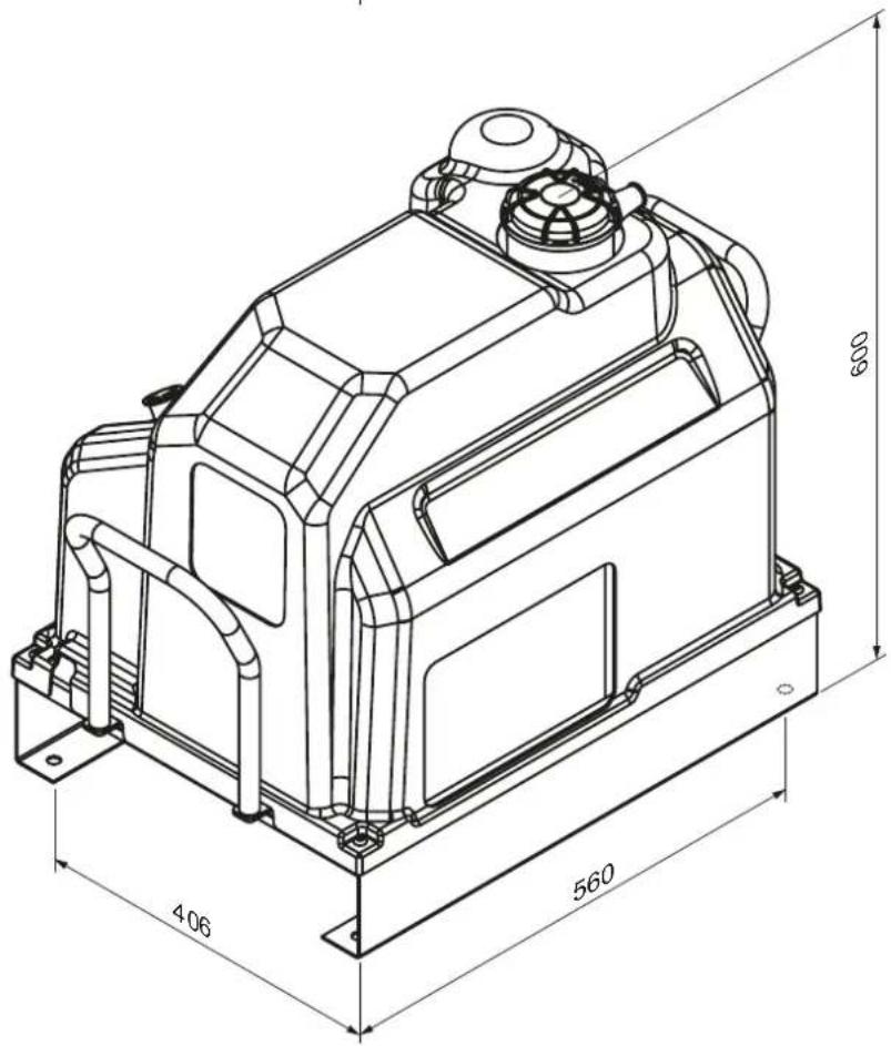
3. SIKKERHETSFORSKRIFTER
GENERELLE ADVARSLER
SPESIALISERT PERSONELL!
BESKRIVELSE AV KOMPRESSOREN (fig. 1-1a)
ELEKTRISK TILKOBLING (fig. 3)
Prosedyre for nedstengning:
ALARMER OG VEDLIKEHOLD
VARMERELEMENT (TILVALGSSETT) (fig. 6)
Anbefales for maskiner med ikke-kontinuerlige driftssykluser. Varmeelementet som er nedsenket i oljen i oljeoppsamlingstanken (fig. 6), holder oljen varm og forhindrer at det dannes for mye kondens.
9. VEDLIKEHOLD
natural_image
Technical line drawing of an industrial pump system with labeled component 'c' (no text or symbols beyond label)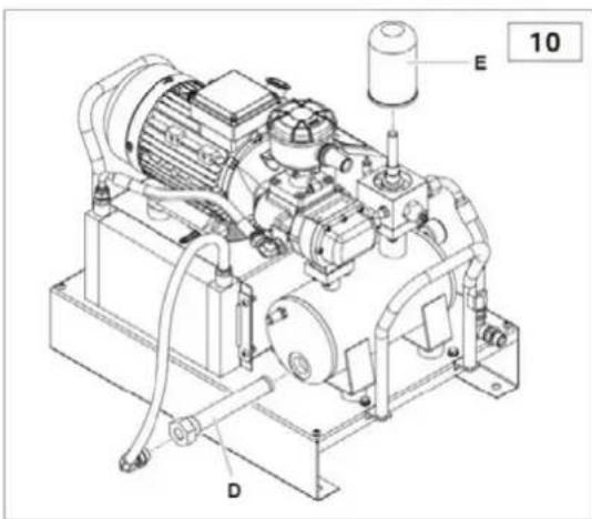
ADVARSEL: Utskiftningene må utføres samtidig med oljeskiftet.
OLJESKIFT
Når kompressortemperaturen overstiger 70 °C, skal oljen skiftes på følgende måte:
| Ref. | Betegnelse | 2,2 KW |
| TC | TRANSFORMATOR 80 VA 230 V-0 V§ 24 V-0 V | |
| ST | TEMPERATURSONDE | |
| BP | TRYKKSENSOR | |
| SB | N∅DKNAPP + nr. 2NC 230 V 10 A | |
| FU1-FU2 | Transformer KERAMISKE sikringer | 1 A |
| FU3 | 2x CERAMIC FUSE 230 V Motor | 16 A |
| FU4 | Sekundær KERAMISK SIKRING 24 V | 1 A |
| FU5 | KERAMISK SIKRING 230 V relé | 2 A |
natural_image
Technical line drawing of a mechanical device with dimension annotations (465 and 618), no readable text or symbols beyond measurement lines.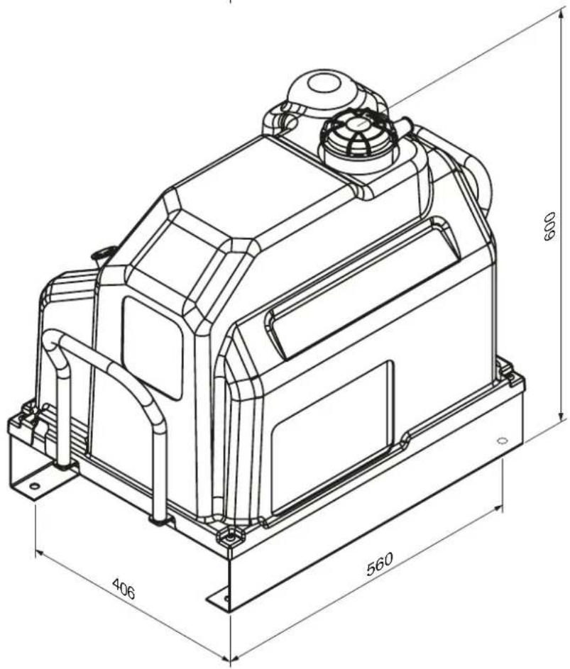
3. БЕЗБЕДНОСНИ ПРОПИСИ
natural_image
Technical line drawing of a mechanical assembly with pipes and bolts (no text or symbols)9. ОДРЖУВАЊЕ
natural_image
Technical line drawing of an industrial pump system with labeled components (no text or symbols present)natural_image
Technical line drawing of a mechanical pump assembly with labeled components (E, D) and part number 10 (no text or symbols beyond labels)| Реф. | Деноминација | 2,2 kW | 3 kW |
| ТК | ТРАНСФОРМАТОР 80 VA 400 V-0 VСек. 24 V-0 V | ||
| СТ | СОНДА ЗА ТЕМПЕРАТУРА | ||
| БП | СЕНЗОР ЗА ПРИТИСОК | ||
| СБ | КОПЧЕ ЗА ИТНИ СЛУЧАИ + бр. 2НЦ 230 V 10 А | ||
| ФУ1-ФУ2 | Трансформаторски керамички осигурувачи | 1 A | 1 A |
| FU3 | 2х КЕРАМИЧКИ ОСИГУРУВАЧ 400 V Мотор | 10 A | 12 A |
| FU4 | Секундарен КЕРАМИЧКИ ОСИГУРУВАЧ 24 V | 1 A | 1 A |
| FU5 | КЕРАМИЧКИ ОСИГУРУВАЧ 230 V реле | 2 A | 2 A |
SKU-të: 360903-C, 360903-C1, 360903-CG
DEKLARATË PËRKONFORMITETI
natural_image
Technical line drawing of a mechanical device with dimension annotations (465 and 618), no readable text or symbols beyond measurement lines.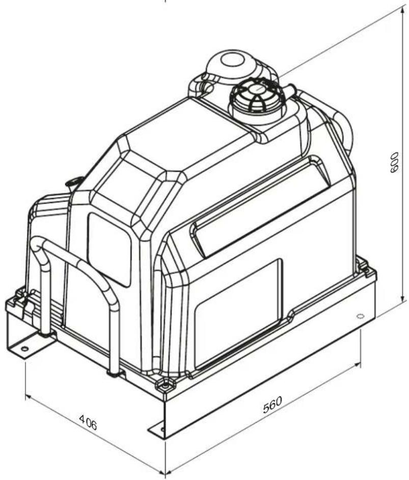
3. RREGULLORET E SIGURISË
PARALAJMËRIME TË PËRGJITHSHME
PËRSHKRIMI I KOMPRESORIT (Fig. 1-1a)
ELEMENTI I NGROHËSIT (PAKETA OPCIONALE) (Fig. 6)
natural_image
Technical line drawing of a mechanical assembly with pipes and components (no text or symbols)CIKLI I OPERIMIT (Fig. 7)
9. MIRËMBAJTJE
PASTRIMI / ZËVENDËSIMI I FILTRIT TË AJRIT
PASTRIMI I RADIATORIT
natural_image
Technical line drawing of an industrial pump system with labeled component 'c' (no text or symbols beyond label)NDRYSHIMI I FILTRIT TË VAJIT
natural_image
Technical line drawing of a mechanical device with dimension annotations (465 and 618), no readable text or symbols beyond measurement lines.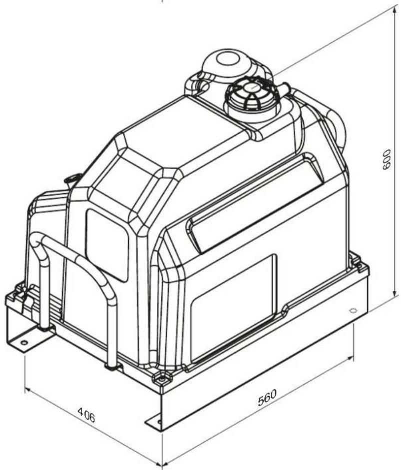
3. БЕЗБЕДНОСНИ ПРОПИСИ
ОПШТА УПОЗОРЕЊА
ГРЕЈАЧ (ОПЦИОНАЛНИ КОМПЛЕТ) (Сл. 6)
natural_image
Technical line drawing of a mechanical assembly with pipes and components (no visible text or symbols)9. ОДРЖАВАНЬЕ
natural_image
Technical line drawing of an industrial pump or compressor unit with labeled component 'c' (no text or symbols beyond label)| Реф. | Деноминација | 2,2 kW | 3 kW |
| ТЦ | ТРАНСФОРМАТОР 80 VA 400 V-0 VЧлан 24 V-0 V | ||
| СТ | ТЕМПЕРАТУРНА СОНДА | ||
| БП | СЕНЗОР ПРИТИСКА | ||
| СБ | Дугме за хитне случајеве + бр. 2НЦ 230 В 10 А | ||
| ФУ1-ФУ2 | КЕРАМИЧКИ ОСИГУРАЧИ ЗАТРАНСФОРМАТОРЕ | 1 А 1 А | |
| ФУ3 | 2х КЕРАМИЧКИ ОСИГУРАЧ Мотор 400 V | 10 А | 12 А |
| ФУ4 | Секундарни керамички осигурач 24 V | 1 А | 1 А |
| ФУ5 | КЕРАМИЧКИ ОСИГУРАЧ Релеј 230 V | 2 А | 2 А |
FÖRSÄKRAN OM ÖVERENSSTÄMMELSE
Denna deklaration bifogas luftkompressorn i original.
INNEHÅLLSFÖRTECKNING
- ALLMÄN INFORMATION
- ÖVERGRIPANDE MÄTT (I MM)
- SÄKERHETSFÖRESKRIFTER
- INSTALLATION
- TEKNISKA DATA
- REGLAGE OCH INSTÄLLNINGAR
- ALARMER
- DRIFT
- UNDERHÅLL
- FELSÖKNING
- LEDNINGSDIAGRAM
1. ALLMÄN INFORMATION
STANDARDUTRUSTNING
natural_image
Technical line drawing of a mechanical device with dimension annotations (465 and 618), no readable text or symbols beyond measurement lines.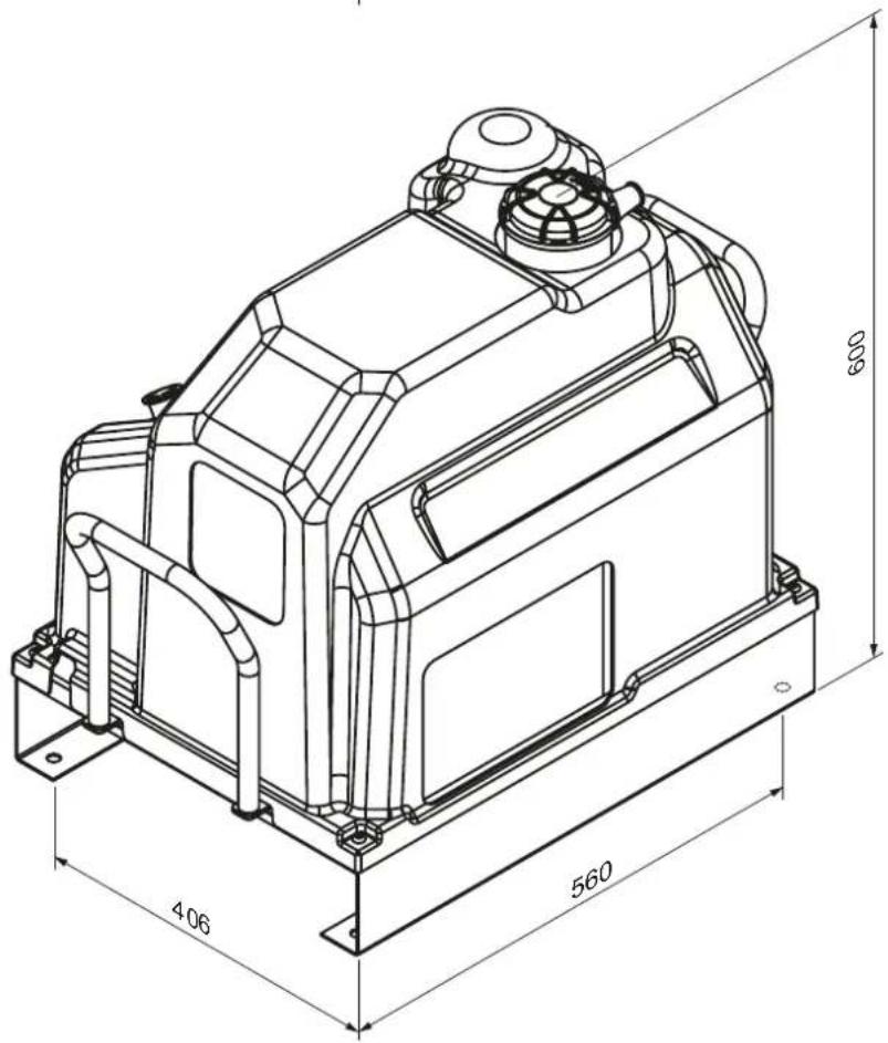
3. SÄKERHETSFÖRESKRIFTER
ALLMÄNNA VARNINGAR
BESKRIVNING AV KOMPRESSORN (Fig. 1-1a)
9. UNDERHÅLL
natural_image
Technical line drawing of an industrial pump system with labeled components (no text or symbols beyond labels)RENGÖRING AV KYLAREN
natural_image
Technical line drawing of a mechanical device with dimension annotations (465 and 618), no readable text or symbols beyond measurement lines.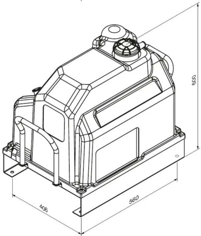
3. SIKKERHEDSFORSKRIFTER
GENERELLE ADVARSLER
BESKRIVELSE AF KOMPRESSOREN (fig. 1-1a)
ELEKTRISK TILSLUTNING (fig. 3)
natural_image
Technical line drawing of a mechanical assembly with labeled parts (no readable text or symbols)BETJENINGSCYKLUS (fig. 7)
natural_image
Technical line drawing of an industrial pump or compressor unit with labeled component 'c' (no text or symbols beyond label)RENG∅RING AF RADIATOREN
- APS 3 COMBI COMPACT
- DECLARATION OF CONFORMITY
- EN
- TABLE OF CONTENTS
- GENERAL INFORMATION
- STANDARD EQUIPMENT
- MACHINE CONDITION AT THE TIME OF DELIVERY
- OVERALL DIMENSIONS (IN MM)
- SAFETY REGULATIONS
- GENERAL WARNINGS
- SYMBOLS USED IN THIS MANUAL
- WARNING!
- POWER OFF!
- MACHINE STOPPED!
- SPECIALIZED PERSONNEL!
- SYMBOLS SIGNED ON THE COMPRESSOR
- Read this page carefully before operating the compressor.
- TO DO:
- NOT TO DO:
- PRODUCT IDENTIFICATION
- COMPRESSOR DESCRIPTION (Fig. 1-1a)
- UNPACKING AND ASSEMBLY
- LOCATION (Fig. 2)
- ELECTRICAL CONNECTION (Fig. 3)
- CONTROLS AND SETTINGS
- CONTROL PANEL
- GENERAL DESCRIPTION OF OPERATION
- OPERATION
- Start-up procedure:
- Shutdown procedure:
- PARAMETERS MENU:
- Reading and programming parameters
- USER MENU:
- ALARMS
- ALARMS AND MAINTENANCE
- OPERATION
- SAFETY AND CONTROL DEVICES (Fig. 5)
- HEATER ELEMENT (OPTIONAL KIT) (Fig. 6)
- OPERATING CYCLE (Fig. 7)
- MAINTENANCE
- BEFORE PERFORMING MAINTENANCE, ALWAYS DO THE FOLLOWING:
- CONDENSATION DRAIN
- CONDENSATE IS A POLLUTING MIXTURE!
- OIL CHECK AND TOP UP IN CASE OF NEED
- CLEANING / REPLACEMENT OF AIR FILTER
- CLEANING THE RADIATOR
- OIL FILTER CHANGE
- OIL SEPARATOR FILTER CHANGE
- OIL CHANGE
- WIRING DIAGRAM
- Single-phase Version:
- Three-phase Version:
- 1.
- INFORMACJE OGÓLNE
- DEKLARACJA ZGODNOŚCI
- 2.2.
- WYMIARY GABARYTOWE
- 3.1.
- ZASADY BEZPIECZEŃSTWA
- UWAGI OGÓLNE ODNOŚNIE BEZPIECZEŃSTWA
- DESCRIPTION OF THE COMPRESSOR (fig. 1-1a)
- 5.
- MONTAŻ
- ROZPAKOWANIE I MONTAŻ MASZYNY
- ALARMY I KONSERWACJA
- SERWISOWANIE10.1.
- SERWISOWANIE10.3.
- WYMIANA OLEJU
- BETRIEBSZYKLUS (Abb.6)
- VEILIGHEIDSVOORSCHRIFTEN
- ALGEMENE WAARSCHUWINGEN
- WAT JE NIET MOET DOEN:
- BESCHRIJVING VAN DE COMPRESSOR (Afb. 1-1a)
- VERWARMINGSELEMENT (OPTIONEEL KIT) (afb.6)
- WERKCYCLUS (afb.6)
- OLIEFILTER VERVANGEN
- DÉCLARATION DE CONFORMITÉ
- RÈGLES DE SÉCURITÉ
- AVERTISSEMENTS GÉNÉRAUX
- DESCRIPTION DU COMPRESSEUR (fig. 1-1a)
- RACCORDEMENT ÉLECTRIQUE (fig. 3)
- ÉLÉMENT CHAUFFANT (KIT OPTIONNEL) (fig. 6)
- ENTRETIEN
- REEMPLACEMENT DU FILTRE À HUILE
- BIZTONSÁGI ELŐÍRÁSOK
- ÁLTALÁNOS FIGYELMEZTETÉSEK
- FÜTÖELEM (OPCIONÁLIS KÉSZLET) (6. ábra)
- MÜKÖDÉSI CIKLUS (7. ábra)
- KARBANTARTÁS
- NORME DE SIGURANTĂ
- AVERTISMENTE GENERALE
- DESCRIEREA COMPRESORULUI (Fig. 1-1a)
- ELEMENT DE ÎNCĂLZIRE (KIT OPTIONAL) (Fig. 6)
- CICLUL DE FUNCTIONARE (Fig. 7)
- ÎNTRETINERE
- CURĂȚAREA / ÎNLOCUIREA FILTRULUI DE AER
- BEZPEČNOSTNÉ PREDPISY
- VŠEOBECNÉ UPOZORNENIA
- POPIS KOMPRESORA (obr. 1-1a)
- Vykurovací prvok (VOLITEL'NÁ SADA) (obr. 6)
- PRACOVNÝ CYKLUS (obr. 7)
- KONDENZÁT JE ZNEČISTUJÚCA ZMES!
- ČISTENIE / VÝMENA VZDUCHOVÉHO FILTRA
- VARNOSTNI PREDPISI
- SPLOŠNA OPOZORILA
- OPIS KOMPRESORJA (slika 1-1a)
- ELEKTRIČNA PRIKLJUČITEV (slika 3)
- OGREVALNI ELEMENT (izbirni komplet) (slika 6)
- VZDRŽEVANJE
- ATBILSTĪBAS DEKLARĀCIJA
- DROŠĪBAS NOTEIKUMI
- VISPĀRĪGI BRĪDINĀJUMI
- KOMPRESSORA APRAKSTS (1-1a. attëls)
- ELEKTRISKAIS SAVIENOJUMS (3. attëls)
- ELLAS NOMAINA
- SAUGOS TAISYKLÈS
- BENDRIEJI JSPÈJIMAI
- KOMPRESORIAUS APRAŠYMAS (1-1a pav.)
- ELEKTRINIS SUJUNGIMAS (3 pav.)
- ŠILDYMO ELEMENTAS (PAPILDOMAS RINKINYS) (6 pav.)
- VEIKSMO CIKLAS (7 pav.)
- ORO FILTRO VALYMAS / KEITIMAS
- ALYVOS FILTRO KEITIMAS
- SIGURNOSNI PROPISI
- OPĆA UPOZORENJA
- OPIS KOMPRESORA (SI. 1-1a)
- RASPAKIRAVANJE I SASTAVLJANJE
- ELEKTRIČNI PRIKLJUČAK (SI. 3)
- KONTROLE I POSTAVKE
- UPRAVLJAČKA PLOČA
- OPĆI OPIS RADOVA
- OPERACIJA
- GRIJAČ (OPCIONALNI KOMPLET) (SI. 6)
- RADNI CIKLUS (SI. 7)
- ČIŠĆENJE RADIJATORA
- IZMJENA FILTRA ULJA
- BEZPEČNOSTNÍ PŘEDPISY
- OBECNÁ UPOZORNĚNÍ
- POPIS KOMPRESORU (obr. 1-1a)
- ELEKTRICKÉ PŘIPOJENÍ (obr. 3)
- TOPNÝ ELEMENT (VOLITELNÁ SOUPRAVA) (obr. 6)
- ÚDRŽBA
- ČIŠTĚNÍ CHLADIČE
- OHUTUSNÕUDED
- ÜLDISED HOIATUSED
- KOMPRESSORI KIRJELDUS (joonis 1-1a)
- ELEKTRILISED ÜHENDUSED (joonis 3)
- HÄIRESIGNAALID JA HOOLDUS
- KÜTTEELEMENDI (VALIKLIK KIT) (joonis 6)
- TÖÖÖTSÜSTEEM (joonis 7)
- ÖLIFILTRI VAHETUS
- NORME DI SICUREZZA
- AVVERTENZE GENERALI
- DESCRIZIONE DEL COMPRESSORE (Fig. 1-1a)
- CICLO OPERATIVO (Fig. 7)
- MANUTENZIONE
- NORMAS DE SEGURANÇA
- AVISOS GERAIS
- DESCRIÇÃO DO COMPRESSOR (Fig. 1-1a)
- ELEMENTO AQUECEDOR (KIT OPCIONAL) (fig.6)
- MANUTENÇÃO
- ELEMENTO CALEFACTOR (KIT OPCIONAL) (fig.6)
- MANTENIMIENTO
- CAMBIAR EL FILTRO DE ACEITE
- ПРАВИЛА БЕЗПЕКИ
- ОЧИЩЕННЯ РАДІАТОРА
- TURVALLISUUSMÄÄRÄYKSET
- YLEISET VAROITUKSET
- TOIMINNAN YLEINEN KUVAUS
- LÄMMITINOSA (VALINNAINEN SARJA) (kuva 6)
- HUOLTO
- ÖLJYN TARKASTUS JA TÄYDENNYS TARVITTAESSA
- JÄÄHDYTTIMEN PUHDISTAMINEN
- SIKKERHETSFORSKRIFTER
- GENERELLE ADVARSLER
- SPESIALISERT PERSONELL!
- BESKRIVELSE AV KOMPRESSOREN (fig. 1-1a)
- ELEKTRISK TILKOBLING (fig. 3)
- Prosedyre for nedstengning:
- ALARMER OG VEDLIKEHOLD
- VARMERELEMENT (TILVALGSSETT) (fig. 6)
- VEDLIKEHOLD
- OLJESKIFT
- БЕЗБЕДНОСНИ ПРОПИСИ
- ОДРЖУВАЊЕ
- SKU-të: 360903-C, 360903-C1, 360903-CG
- DEKLARATË PËRKONFORMITETI
- RREGULLORET E SIGURISË
- PARALAJMËRIME TË PËRGJITHSHME
- PËRSHKRIMI I KOMPRESORIT (Fig. 1-1a)
- ELEMENTI I NGROHËSIT (PAKETA OPCIONALE) (Fig. 6)
- CIKLI I OPERIMIT (Fig. 7)
- MIRËMBAJTJE
- PASTRIMI / ZËVENDËSIMI I FILTRIT TË AJRIT
- PASTRIMI I RADIATORIT
- NDRYSHIMI I FILTRIT TË VAJIT
- ОПШТА УПОЗОРЕЊА
- ГРЕЈАЧ (ОПЦИОНАЛНИ КОМПЛЕТ) (Сл. 6)
- ОДРЖАВАНЬЕ
- FÖRSÄKRAN OM ÖVERENSSTÄMMELSE
- INNEHÅLLSFÖRTECKNING
- ALLMÄN INFORMATION
- STANDARDUTRUSTNING
- SÄKERHETSFÖRESKRIFTER
- ALLMÄNNA VARNINGAR
- BESKRIVNING AV KOMPRESSORN (Fig. 1-1a)
- UNDERHÅLL
- RENGÖRING AV KYLAREN
- SIKKERHEDSFORSKRIFTER
- BESKRIVELSE AF KOMPRESSOREN (fig. 1-1a)
- ELEKTRISK TILSLUTNING (fig. 3)
- BETJENINGSCYKLUS (fig. 7)
- RENG∅RING AF RADIATOREN
Brand : Airpress
Model : APS 3 Combi Compact
Category : Compressor