
IS-VS1A.RG - Mobile Phone i.safe Mobile - Free user manual and instructions
Find the device manual for free IS-VS1A.RG i.safe Mobile in PDF.

| Product type | Valve inspection system with integrated smartphone |
| Brand | i.safe Mobile |
| Model | IS-VS1A.RG (set with IS540.RG smartphone) |
| Power supply | Lithium-ion battery BPIS540.RGA (for smartphone), universal power adapter 5 V / 2 A |
| Included sensors | 2 ultrasonic sensors IS-SU150F1.1 (100-450 kHz) and IS-SU150F2.1 (100-450 kHz), waveguide, locking mechanism, coupling agent |
| Main functions | Acoustic detection of valve leaks, artificial intelligence evaluation via Senseven app, 5-point measurement, result display (leak / no leak) |
| Mobile app | Senseven (available on IS540.RG smartphone), cloud synchronization via https://cloud.senseven.ai |
| Connectivity | Smartphone with SIM card or eSIM, internet connection required for installation only |
| Cleaning | Soft, damp, antistatic cloth, no chemicals |
| Storage | Humidity 10-60 %, temperature: -20°C to +45°C (1 month), -10°C to +35°C (3 months), -10°C to +25°C (>3 months) |
| Safety | Do not use in explosive areas, do not modify the device, follow local regulations |
| Warranty | Terms available at www.isafe-mobile.com/fr/support/service |
| Repairability | After-sales service i.safe MOBILE GmbH (www.isafe-mobile.com/fr/support/service), annual check recommended |
| Package contents | IS540.RG smartphone, IS-VS1A.RG measurement electronics, 2 sensor cables, 2 sensors, waveguide, locking mechanism, coupling agent, coupling film, housing, battery, screen protector, screwdriver, USB-C cable, power adapter with AU/EU/UK/US plugs, safety instructions |
Frequently Asked Questions - IS-VS1A.RG i.safe Mobile
User questions about IS-VS1A.RG i.safe Mobile
0 question about this device. Answer the ones you know or ask your own.
Ask a new question about this device
Download the instructions for your Mobile Phone in PDF format for free! Find your manual IS-VS1A.RG - i.safe Mobile and take your electronic device back in hand. On this page are published all the documents necessary for the use of your device. IS-VS1A.RG by i.safe Mobile.
USER MANUAL IS-VS1A.RG i.safe Mobile
natural_image
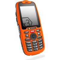
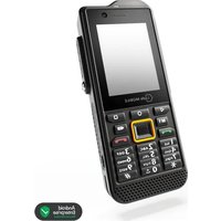
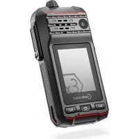
Exterior view of a black Lgate Mobile phone with attached sensor and flashlight (no visible text or symbols on device body)VALVE SENSE INSPECTION
OPERATING MANUAL
IS-VS1A.RG | MODEL MVS1A01
Document No. 1080MM10REV01
Version: 2025-03-21
i.safe MOBILE GmbH
i_Park Tauberfranken 10
97922 Lauda-Koenigshofen
Germany
Tel.+49 9343 60148-0
info@isafe-mobile.com
www.isafe-mobile.com
(c) 2025 i.safe MOBILE GmbH Template: TEMPMM01REV10
CONTENTS
English 4
Deutsch....18
Česky 32
Dansk 46
Español....60
Suomi....74
Français....88
Magyar 102
Italiano 116
Nederlands 130
Norsk 144
Polski 158
This Operating Manual complies with these standards:
IEC 60079, IEC 82079, ANSI Z535.6
IEC 60079, IEC 82079, ANSI Z535.6
ENGLISH
This Operating Manual is part of the device IS-VS1A.RG (model MVS1A01). This Operating Manual provides important information for safe use of the device.
» Before using the device, read this Operating Manual carefully and pay particular attention to the „Safety“ information highlighted with the warning symbol.
» Also read the Safety Instructions before using the device. You can find these at www.isafe-mobile.com/en/support/downloads
» Make sure you have access to this Operating Manual when you need it. You can find the current Operating Manual at www.isafe-mobile.com/en/support/downloads
» Follow all instructions given on the device and on the packaging.
»Follow local safety regulations.
» Do not use the device in explosion hazardous areas.
» Do not modify the device structurally.
» Do not expose the device to high temperatures.
» Do not expose the device to strong UV radiation.
» Do not expose the device to processes with high electrical charges.
» Do not expose the device to aggressive acids or bases.
INTENDED USE
The IS-VS1A.RG Valve Sense inspection system detects and processes acoustic signals from a leaking valve. Acoustic emission sensors pick up these signals and send them to the IS540.RG Smartphone via measurement electronics for processing. With the help of algorithms and artificial intelligence, the Senseven App automatically evaluates the sensor signals and indicates whether a valve is leaking or not. Valves therefore only have to be replaced if they are actually defective, and functioning valves can continue to be used. The test is carried out in the course of operation during the production process.
Only use the device as described in this Operating Manual. Any other use is considered improper and can lead to death, severe injuries and damage to the device.
The manufacturer i.safe MOBILE GmbH does not assume any liability for damage caused by improper use. The warranty expires in the event of improper use.
USER
Only trained users who have read and understood this Operating Manual may use this device.
WARRANTY
You can find the warranty conditions at www.isafe-mobile.com/en/support/service For any damage caused by computer viruses that you download while using the Internet functions responsibility is at your hand. There is no right of recourse against i.safe MOBILE GmbH.
EU DECLARATION OF CONFORMITY
You will find the EU declaration of conformity at www.isafe-mobile.com/en/support/downloads
>SCOPE OF DELIVERY
Your device packaging contains the following:
1 x IS540.RG Smartphone
1 x IS-VS1A.RG Measurement Electronics
2 x IS-SC120BB1.1 Sensor Cable
1 x IS-SU150F1.1 Sensor Ultrasonic
1 x IS-SU150F2.1 Sensor Ultrasonic
1 x IS-WG22.1 Waveguide
1 x IS-WGLF1.1 Waveguide Lock
1 x IS-USC1.1 Coupling Agent
1 x Coupling film
1 x Case incl. shadowboard IS-VS1A.RG
1 x BPIS540.RGA Battery
1 x Display Protection Foil IS540.x
1 x Torx Screwdriver T8
1 x USB-C Cable
1 x Power Supply Unit universal 5 V/2 A
1 x Plug AU
1 x Plug EU
1 x Plug UK
1 x Plug US
1 x Safety Instructions IS540.RG
1 x Safety Instructions IS-VS1A.RG
>DEVICE OVERVIEW/FUNCTIONS
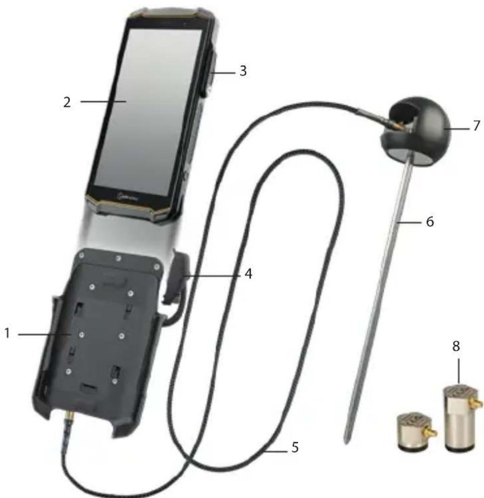
1>MEASUREMENT ELECTRONICS
2> IS540.RG SMARTPHONE
3) 16-PIN ISM INTERFACE: Connection for the 16-pin ISM connector
4) 16-PIN ISM CONNECTOR: Connection to the ISM interface on the smartphone
5) SENSORCABLE : Connection between sensor and measurement electronics
6) WAVEGUIDE: Waveguides for cold (< -50 °C (< -58 °F)) and hot (> 120 °C (> 248 °F)) surfaces
7) WAVEGUIDE LOCK: Holder for the sensor when using the Waveguide
8) SENSORS
SENSORS
The sensors are suitable for different areas of application:
Sensor Specifications Area of application
| IS-SU150F1.1Sensor Ultrasonic | Frequency range:100 - 450 kHzHeight: 18,2 mm (0.72 in) | Use with the Waveguide for cold (< -50 °C (< -58 °F)) and hot (> 120 °C (> 248 °F)) surfaces.Use directly on the valve without the Waveguide.For leakage volume *1, see “Measurable leakage volumes (examples)” table. |
| IS-SU150F2.1Sensor Ultrasonic | Frequency range:100 - 450 kHzHeight: 37,5 mm (1.48 in) | Use directly on the valve.For leakage volume *1, see “Measurable leakage volumes (examples)” table. |
| IS-SU030F2.1Sensor Ultrasonic (available as an option) | Frequency range:25 - 80 kHzHeight: 37,5 mm (1.48 in) | Use directly on the valve.Use in quiet environments.For leakage volume *2, see “Measurable leakage volumes (examples)” table. |
MEASURABLE LEAKAGE VOLUMES (EXAMPLES)
Medium Min. pressure differential Measurable leakage volumes
| Water 2 - 3 bar (29 - 43,5 psi) | Leak rate *1:0,1 l/min (3.8 fl oz/min)Leak rate *2:0,01 l/min (0.34 fl oz/min)Gate valve 25 mm (1 in),10 bar (145 psi) |
| Gas 1 bar (14,5 psi) | Leak rate *1:0,06l/min (2.03 fl oz/min)Ball valve 25 mm (1 in), 10 bar (145 psi) |
| Steam 1 bar (14,5 psi) | Leak rate *1: 0,22 kg/h (0.49 lb/h)Globe valve 50mm (2 in) |
| Air 1 bar (14,5 psi) | Leak rate *1:0,12l/min (4.06 floz/min)Ball valve 25 mm (1 in), 4 bar (58 psi) |
INSTALLATION
INSTALLATION OF MEASUREMENT ELECTRONICS
» Set up an Internet connection for the installation. An Internet connection is not required after installation.
» When using it for the first time, insert a SIM card into the smartphone or activate the eSIM (see Operating Manual for Smartphone IS540.RG).
» Insert the battery into the smartphone and hand-tighten the battery (see Operating Manual for Smartphone IS540.RG).
»Turn on the smartphone.
» Follow the on-screen instructions.
You can find help on how to use the Senseven App at www.senseven.ai

» Slide the IS540.RG Smartphone (2) into the mount on the measurement electronics device (1).
»Connect the plug (4) of the measurement electronics device securely to the 16-pin ISM interface (3) on the smartphone (see Operating Manual IS540.RG Smartphone).
WAVEGUIDES FOR COLD (< -50 °C (< -58 °F)) OR HOT (> 120 °C (> 248 °F)) SURFACES
When performing measurements with the Waveguide, use the IS-SU150F1.1 Sensor Ultrasonic.
» Unscrew the Waveguide (6) and slide the sensor (8) into the Waveguide Lock (7) with the labeling pointing towards the spring.
» Apply the couplant to the measuring surface of the sensor.
» Screw the Waveguide back onto the Waveguide Lock.
SENSORS
For measurements without the Waveguide, use the IS-SU150F2.1 Sensor Ultrasonic or, optionally, the IS-SU030F2.1 Sensor Ultrasonic (for quiet environments, with low leakage volumes).
» Plug the sensor cable (5) into the connector labeled "SENSOR".
» Connect the other end of the sensor cable to the sensor (8).
» Clean the measuring area of the sensor with a soft, lint-free antistatic cloth.
» When using the IS-SU150F2.1 Sensor Ultrasonic, stick the coupling foil onto the measuring surface of the sensor.
» When using the IS-SU030F2.1 Sensor Ultrasonic, apply the couplant to the measuring surface of the sensor.
MEASUREMENT
PREPARE MEASUREMENT
» Make sure the valve is closed.
» If possible, remove any existing insulation still on the valve. If the insulation cannot be removed, access the measuring point through a hole in the insulation (diameter 10 - 12 mm (0.39 - 0.47 in)).
» Determine the valve ID (possibly label on the valve).
» Determine the flow medium (possibly information on the pipe).
» Check whether there is a pressure difference at the valve (possibly displayed on the pressure gauge or via the process control system). For a correct measurement, there must be a pressure difference according to the table in the „Device overview/Functions“ section.
» Determine the flow direction of the medium in the valve (possibly arrow on the pipe/valve).
PERFORM MEASUREMENT
» Turn on the smartphone and open the Senseven App.
»Follow the on-screen instructions.
You can find help on how to use the Senseven App at www.senseven.ai
Once you have selected the valve type in the Senseven App, the app will show the ideal measuring points (M1, M2, etc. in the valve drawing), specifying where you have to place the sensor for the measurement. In general, the ideal distance between the measuring points depends on the pipe diameter and is measured from the valve flange:
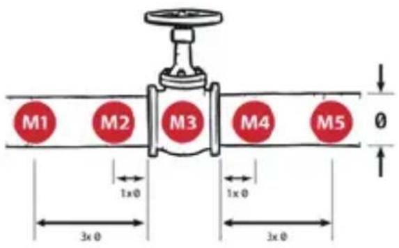
» Carry out the measurement with 5 measuring points (recommended).
» Press the sensor onto each individual measuring point.
»To start the measurement, you can either tap the „Measure“ button in the Senseven App or press the left side button on the IS540.RG Smartphone.
» Make sure that the contact pressure is as even as possible at the individual measuring points during the measuring process.
» Make sure the sensor does not slip while measuring.
REPEAT MEASUREMENT
The measuring software checks whether the measurement needs to be repeated for each measurement point. At least one repeat measurement is required for the measuring points on the pipe (M1, M2, M4, M5). At least two repeat measurements are necessary at measuring point M3.
» If specified by the Senseven App, repeat the measurement at the measuring point.
If the system detects significantly different measurement signals at a measurement point (10 dB deviation), you will receive a message in the Senseven app.
After the last measurement, the Senseven App automatically displays the result of the measurement (Leak/No Leak).
In a further step, you can then add details to the measurement, take a photo and save the measurement. As soon as the system has an Internet connection, all measurements are automatically synchronized with the back office (https://cloud.senseven.ai).
FAULTS
Possible faults can be rectified as follows:
| Fault Cause Remedy | ||
| Problems using the Senseven app | Press the help button in the Senseven app.See the "Guide" screen for more information and instructions | |
| Significantly different measurement signals at one measurement point | Process sequence not smoothPumps switch on/off, valves open/close | Repeat the measurement at least once.Watch the process. Do not measure again until the process is stable. |
| Incorrect measurement result | Coupling foil dirty (when used without Waveguide) | Remove the coupling foil.Clean the measuring area of the sensor with a soft, lint-free antistatic cloth.Stick new coupling foil to the measuring surface of the sensor. |
| Insufficient cou-plant (when using the Waveguide and the IS-SU030F2.1 Sensor Ultrasonic) | Apply the couplant between the sensor and the Waveguide, or to the measuring surface of the IS-SU030F2.1 Sensor Ultrasonic. | |
| Insufficient contact pressure | Repeat the measurement, increasing the contact pressure. | |
| Sensor moves/slips | Repeat the measurement, making sure that the sensor does not move during the measurement. | |
| Wrong measuring point | Repeat the measurement, performing the measu-rement at the measurement points displayed in the Senseven App. | |
| Sensor cable not plugged in correctly | Plug the sensor cable into the connector marked „SENSOR" and check that it is seated properly. | |
| Interference noise | Curves, T-fittings and currents | Locate the source of the noise. Then carry out the measurement with 5 measuring points. Set the first or last measuring point closer to the noise source.If the signal gets stronger in the direction of the noise source, it indicates a source of interference (curves, T-fittings and currents).Repeat the measurement and observe the trend in the trend view(see Backoffice/Cloudhttps://cloud.senseven.ai).If the signal weakens over time, the process is stabilizing.Do not measure again until the process is stable. |
POSSIBLE DEVICE PROBLEMS
You can find information on possible device problems and how to rectify them at www.isafe-mobile.com/en/support/service under the menu item "FAQ".
If you have any further questions, please contact the i.safe MOBILE GmbH repair service at www.isafe-mobile.com/en/support/service
You can find help on how to use the Senseven App at www.senseven.ai
MAINTENANCE/REPAIR
MAINTENANCE
| Activity Tools Interval | ||
| Clean sensors Soft, lint-free, antitatic cloth In the case of heavy soiling before applying the coupling agent or the coupling foil.When changing the coupling foil. | ||
| Apply couplant (when using the Waveguide and the IS-SU030F2.1 Sensor Ultrasonic) | IS-USC1.1 Coupling Agent When using the Waveguide: every 100 measurements or every 2 - 3 months. | |
| Change coupling foil (when used without Waveguide) | Coupling film If the coupling foil is heavily soiled. | |
| System Check „CCT" connection to the measurement electronics, second sensor cable, second sensor, Senseven App. | When requested by the Senseven App or if the sensor is damaged. | |
| Recommendation: Annual testing of sensors and measuring electronics (carried out only in service centers) | Service centre Yearly | |
SYSTEM CHECK
» Plug the sensor cable into the connector labeled "SENSOR".
» Connect the end of the sensor cable to the sensor to be tested.
» Plug the second sensor cable into the connector labeled "CCT".
» Connect the end of the sensor cable to the second sensor.
» Clean the measuring surface of the sensors with a soft, lint-free, antistatic cloth.
» Stick the coupling foil to the measuring surface of one of the connected sensors.
» Press both sensors together on the measuring surfaces and start the System Check (Senseven App).
» Follow the on-screen instructions.
The following messages may appear on the display after the System Check:
| Message(Senseven App) | Cause Further action | |
| "X Hardware connection" | Side connection faultyMeasurement electronics faulty | Send the complete Valve Sense Inspection Set to thei.safeMOBILE GmbHrepair service. |
| "X Coupling" One of the two | cables is faultyBoth cables faultyOne of the sensors is faultyBoth sensors faultyNo coupling foil present | Orange message:Stick on the coupling foil and carry out a System Check.If the error message appears again, send the complete Valve Sense Inspection Set to thei.safe MOBILE GmbHrepair service.Red message:Send the complete Valve Sense Inspection Set to thei.safe MOBILE GmbHrepair service in any case. |
Green message: No Valve Sense Inspection Set error.
REPAIR
Contact the i.safe MOBILE GmbH repair service at
www.isafe-mobile.com/en/support/service if the device is not working normally, if the device needs to be repaired or if a replacement part is required.
RETURN SHIPMENT
Contact the i.safe MOBILE GmbH repair service at
www.isafe-mobile.com/en/support/service
DISTRIBUTION PARTNER
You can find the specialist distribution partner responsible for your country at www.isafe-mobile.com/en/contact
CLEANING
NOTICE
Incorrect cleaning can cause damage to the device. Please note the following when cleaning:
» Do not use chemical agents for cleaning.
» Clean the device with a soft, moistened antistatic cloth.
STORAGE
NOTICE
Incorrect storage can cause damage to the device.
» Store the device at a humidity of 10 % to 60 % at the following ambient temperatures:
Up to one month: -20 °C to +45 °C (-4 °F to +113 °F)
Up to 3 months: -10 °C to +35 °C (+14 °F to +95 °F)
Over 3 months: -10 °C to +25 °C (+14 °F to +77 °F)
» Disconnect the IS540.RG from the measurement electronics.
» For longer storage without use, remove the battery from the IS540.RG.
RECYCLING
NOTICE
Incorrect disposal of electronic products, batteries and packaging material puts the environment at risk. Please note the following when disposing of items:
» DO NOT throw away batteries with household waste.
» Always dispose electronic products, batteries and packaging material at the appropriate collection points. This way, you prevent uncontrolled waste disposal and promote the recycling of material resources.
You can obtain further information from regional waste disposal companies, state authorities or the i.safe MOBILE GmbH service centre responsible for your country or region at www.isafe-mobile.com/en/support/service

TRADEMARKS
i.safe MOBILE GmbH and the i.safe MOBILE GmbH logo are registered trademarks of the i.safe MOBILE GmbH.
All other trademarks and copyrights are the properties of their respective owners.
DEUTSCH
www.isafe-mobile.com/en/support/downloads
ROZSAH DODÁVKY
MĚŘITELNÉ OBJEMY ÚNIKU (PŘÍKLADY)
1) MÅLEELEKTRONIK
2) SMARTPHONE
3) 16-BENS ISM-GRÅENSEFLADE: Tilslutning til 16-bens ISM-stik
4) 16-BENS ISM-STIK: Tilslutning til ISM-grænseflade på en smartphone
5) SENSORKABEL: Tilslutning mellem sensor og måleelektronik
6) WAVEGUIDE: Waveguides til kolde (< -50 °C (< -58 °F)) og varme (> 120 °C (> 248 °F)) overflader
7) WAVEGUIDE-LÅS: Holder til sensoren, när waveguiden anvendes
8) SENSORER
SENSORER
www.isafe-mobile.com/en/support/service
DETAILPARTNER
Du kan finde den specialiserede detailpartner med ansvar for dit land på www.isafe-mobile.com/en/contact
RENG∅RING
BEMÆRK
www.isafe-mobile.com/en/support/service
www.isafe-mobile.com/en/support/downloads
>ALCANCE DEL SUMINISTRO
www.isafe-mobile.com/en/support/downloads
TOIMITUSSISÄLTÖ
DÉCLARATION DE CONFORMITÉ UE
www.isafe-mobile.com/en/support/service
VOLUMI PERDITE MISURABILI (ESEMPI)
| Medio Differenziale di pressione min. | Volumi perdite misurabili | |
| Acqua 2 - 3 bar (29 - 43,5 psi) | Tasso di perdita *1:0,1 l/min (3.8 fl oz/min)Tasso di perdita *2:0,01 l/min (0.34 fl oz/min)Valvola a saracinesca 25 mm (1 in),10 bar (145 psi) | |
| Gas 1 bar (14,5 psi) | Tasso di perdita *1:0,06l/min (2.03 fl oz/min)Valvola a sfera 25 mm (1 in), 10 bar (145 psi) | |
| Vapore 1 bar (14,5 psi) | Tasso di perdita *1: 0,22 kg/h (0.49 lb/h)Valvola a globo 50 mm (2 in) | |
| Aria 1 bar (14,5 psi) | Tasso di perdita *1:0,12l/min (4.06 floz/min)Valvola a sfera 25 mm (1 in), 4 bar (58 psi) | |
>INSTALLAZIONE
1) MÅLEELEKTRONIKK
2> IS540.RG SMARTTELEFON
3) 16-POLERS ISM-GRENSESNITT: tilkobling av den 16-polers ISM-koblingen
4) 16-POLERS ISM-KOBLING: tilkobling til ISM-grensesnittet på smarttelefonen
5) SENSORKABEL: sammenkobling av sensoren og måleelektronikken
6) B∅LGELEDER: Bølgeledere for kalde (< -50 °C (< -58 °F)) og varme (> 120 °C (> 248 °F)) overflater
7) B∅LGELEDERLÅS: Holder for sensoren ved bruk av bølgeleder
8) SENSORER
SENSORER
» Sett IS540.RG-smarttelefonen (2) inn i festet på måleelektronikkenheten (1).
» Koble pluggen (4) på måleelektronikkenheten godt til det 16-polers ISM-grensesnittet (3) på smarttelefonen (se brukerhåndboken for smarttelefon IS540.RG).
B∅LGELEDERE FOR KALDE (< -50 °C (< -58 °F)) ELLER
VARME (> 120 °C (> 248 °F)) OVERFLATER
VEDLIKEHOLD/REPARASJON
VEDLIKEHOLD
www.isafe-mobile.com/en/support/service
DETALJHANDELSPARTNER
www.isafe-mobile.com/en/support/service
MERKER
i.safe MOBILE GmbH og i.safe MOBILE GmbH-logoen er merker fra i.safe MOBILE GmbH.
www.isafe-mobile.com/en/support/service.
www.isafe-mobile.com/en/support/downloads.
1> MJERNA ELEKTRONIKA
2) PAMETNI TELEFON IS540.RG
3) SUČELJE 16-IGLIČNOG ISM-A: Priključak za 16-iglični ISM konektor
4) 16-IGLIČNI ISM KONEKTOR: Spoj na ISM sučelje na pametnom telefonu
5> KABEL SENZORA: Spoj između senzora i mjerne elektronike
6) VALOVOD: Valovodi za hladne (< -50 °C (< -58 °F)) i vruće (> 120 °C (> 248 °F)) površine
7) BLOKADA VALOVODA: Držač senzora kada se koristi valovod
8) SENZORI
SENZORI
» Umetnite pametni telefon IS540.RG (2) u nosač na uređaju mjerne elektronike (1).
» Utikač (4) uređaja za elektroničko mjerenje sigurno spojite na 16-iglično ISM sučelje (3) na pametnom telefonu (pogledajte Priručnik za uporabu pametnog telefona IS540.RG).
VALOVODI ZA HLADNE (< -50 °C (< -58 °F)) ILI VRUĆE (> 120 °C (> 248 °F)) POVRŠINE
Prilikom obavljanja mjerenja valovodom, koristite ultrazvučni senzor IS-SU150F1.1.
» Odvrnite valovod (6) i umetnite senzor (8) u blokadu valovoda (7) tako da oznaka bude usmjerena prema opruzi.
www.isafe-mobile.com/en/support/service
Pomoć za korištenje aplikacije Senseven možete pronaći na www.senseven.ai
ODRŽAVANJE/POPRAVAK
ODRŽAVANJE
| Aktivnost Alati Interval | ||
| Čisti senzori Mekana, antistatička krpa koja ne ostavlja dlačice | U slučaju jakog onečišćenja, pri-je primjene sredstva za spajanje ili folije za spajanje.Promjena folije za spajanje. | |
| Koristite spojnicu (prili-kom obavljanja mjerenja valovodom i ultrazvučnim senzorom IS-SU030F2.1). | IS-USC1.1 Sredstvo za spajanje Prilikom obavljanja mjerenja valovodom: svakih 100 mjerenja ili svaka 2 - 3 mjeseca. | |
| Zamjena folije za spaja-nje (kod korištenja bez valovoda) | Folija za spajanje Ako je folija za spajanje jako zaprljana. | |
| System Check (Provjera sustava) | CCT spoj na mjernu elektroniku, drugi kabel senzora, drugi senzor, aplikacija Senseven | Ako to traži aplikacija Senseven ili ako je senzor oštećen. |
| Preporuka: Godišnje ispitivanje sen-zora i mjerne elektronike (provodi se isključivo u servisnim centrima)) | Servisni centar Godišnje | |
SYSTEM CHECK (PROVJERA SUSTAVA)
» Kabel senzora umetnite u konektor s oznakom „SENSOR”.
» Kraj kabela senzora spojite na senzor koji treba ispitati.
» Kabel drugog senzora umetnite u konektor s oznakom „CCT”.
» Kraj kabela senzora spojite na drugi senzor.
» Očistite mjerno područje senzora mekanom, antistatičkom krpom koja ne ostavlja dlačice.
» Na jedan od priključenih senzora postavite novu foliju za spajanje.
» Istovremeno pritisnite oba senzora na mjernoj površini i započnite System Check (provjeru sustava) (aplikacija Senseven).
» Slijedite upute na zaslonu.
www.isafe-mobile.com/en/support/service
> MALOPRODAJNI PARTNER
Možete pronaći stručnog maloprodajnog partnera odgovornog za svoju državu na www.isafe-mobile.com/en/contact
ČIŠĆENJE
NAPOMENA
www.isafe-mobile.com/en/support/downloads
ROZSAH DODANIA
1> MERACIA ELEKTRONIKA
2) SMARTFÓN IS540.RG
3) 16-KOLÍKOVÉ ROZHRANIE ISM: Pripojenie pre 16-kolíkový konektor ISM
4> 16-KOLÍKOVÝ KONEKTOR ISM: Pripojenie k rozhraniu ISM v smartfóne
5) KÁBEL SENZORA: Pripojenie medzi senzorom a meracou elektronikou
6) VLNOVOD: Vlnovody pre studené (< -50 °C) a horúce (> 120 °C) povrchy
7) ZÁMOK VLNOVODU: Držiak pre senzor pri použití vlnovodu
8) SENZORY
SENZORY
»Zasuňte smartfón IS540.RG (2) do držiaka na zariadení meracej elektroniky (1).
» Pevne pripojte zástrčku (4) zariadenia meracej elektroniky k 16-kolíkovému rozhraniu ISM (3) na smartfóne (pozrite návod na obsluhu smartfónu IS540.RG
VLNOVODY PRE STUDENÉ (< -50 °C) ALEBO HORÚCE (> 120 °C) POVRCHY
www.isafe-mobile.com/en/support/downloads
www.isafe-mobile.com/en/support/downloads
- صل كابل جهاز الاستثماعار (5) بالموصل المسمى „SENSOR„, “SENSOR„, “SENSOR„, “SENSOR„, “SENSOR„, “SENSOR„, “SENSOR„, “SENSOR„, “SENSOR„, “SENSOR„, “SENSOR„, “SENSOR„, “SENSOR„, “SENSOR„, “SENSOR„, “SENSOR„, “SENSOR„, “SENSOR„, “SENSOR„, “SENSOR„, “SENSOR„, “SENSOR„, “SENSOR„, “SENSOR„, “SENSOR„, “SENSOR„, "SENSOR„, “SENSOR„, “SENSOR„, “SENSOR„, “SENSOR„, “SENSOR„, “SENSOR„, “SENSOR„, “SENSOR„, “SENSOR„, “SENSOR„, “SENSOR„, “SENSOR„, “SENSOR„, “SENSOR„, “SENSOR„, “SENSOR„, “SENSOR„, “SENSOR„, “SENSOR„, “SENSOR„, “SENSOR„, “SENSOR„, “SENSOR„, “SENSOR„, ‘SENSOR’
Despite careful control of the content, we do not assume any liability for the content of external links. The respective providers or operators of the websites are exclusively responsible for the content of the linked pages.
CONTACT/SERVICE CENTRE
FOR FURTHER QUESTIONS PLEASE CONTACT OUR SERVICE CENTRE:
» i.safe MOBILE GmbH, i_Park Tauberfranken 10, 97922 Lauda-Koenigshofen, Germany
» support@isafe-mobile.com
» https://support.isafe-mobile.com
ISAFE-MOBILE.COM
- VALVE SENSE INSPECTION
- CONTENTS
- ENGLISH
- INTENDED USE
- USER
- WARRANTY
- EU DECLARATION OF CONFORMITY
- >SCOPE OF DELIVERY
- >DEVICE OVERVIEW/FUNCTIONS
- SENSORS
- MEASURABLE LEAKAGE VOLUMES (EXAMPLES)
- INSTALLATION
- INSTALLATION OF MEASUREMENT ELECTRONICS
- WAVEGUIDES FOR COLD (< -50 °C (< -58 °F)) OR HOT (> 120 °C (> 248 °F)) SURFACES
- MEASUREMENT
- PREPARE MEASUREMENT
- PERFORM MEASUREMENT
- REPEAT MEASUREMENT
- FAULTS
- POSSIBLE DEVICE PROBLEMS
- MAINTENANCE/REPAIR
- MAINTENANCE
- SYSTEM CHECK
- REPAIR
- RETURN SHIPMENT
- DISTRIBUTION PARTNER
- CLEANING
- NOTICE
- STORAGE
- RECYCLING
- TRADEMARKS
- DEUTSCH
- ROZSAH DODÁVKY
- SENSORER
- DETAILPARTNER
- RENG∅RING
- BEMÆRK
- >ALCANCE DEL SUMINISTRO
- TOIMITUSSISÄLTÖ
- DÉCLARATION DE CONFORMITÉ UE
- >INSTALLAZIONE
- B∅LGELEDERE FOR KALDE (< -50 °C (< -58 °F)) ELLER
- VARME (> 120 °C (> 248 °F)) OVERFLATER
- VEDLIKEHOLD/REPARASJON
- DETALJHANDELSPARTNER
- MERKER
- SENZORI
- VALOVODI ZA HLADNE (< -50 °C (< -58 °F)) ILI VRUĆE (> 120 °C (> 248 °F)) POVRŠINE
- ODRŽAVANJE/POPRAVAK
- SYSTEM CHECK (PROVJERA SUSTAVA)
- > MALOPRODAJNI PARTNER
- ČIŠĆENJE
- NAPOMENA
- ROZSAH DODANIA
- SENZORY
- VLNOVODY PRE STUDENÉ (< -50 °C) ALEBO HORÚCE (> 120 °C) POVRCHY
- CONTACT/SERVICE CENTRE
Brand : i.safe Mobile
Model : IS-VS1A.RG
Category : Mobile Phone