
IS330.RG - Mobile Phone i.safe Mobile - Free user manual and instructions
Find the device manual for free IS330.RG i.safe Mobile in PDF.

| Product type | Industrial mobile phone |
| Brand | i.safe Mobile |
| Model | IS330.RG (M33A01) |
| Operating system | Android (version unspecified) |
| Power supply | Rechargeable battery, universal power adapter (plugs for different countries), USB-C cable |
| Charging temperature | +5°C to +35°C (+41°F to +95°F) |
| Main features | Dual SIM, front/rear camera, LED flash, touchscreen, keypad, SOS button, cell broadcast, Internet access |
| Storage | microSD card up to 128 GB (dedicated slot) |
| Connectivity | USB-C (charging and data), 13-pin ISM interface for approved accessories |
| Safety | Non-ATEX – use prohibited in explosive atmospheres |
| Care and cleaning | Turn off device before cleaning; use a soft, damp anti-static cloth (no chemicals) |
| Storage | Temperature: +5°C to +35°C, humidity: 10% to 60% |
| Spare parts and repairability | Approved replacement battery available; no user-serviceable parts; repair by i.safe MOBILE service |
| Box contents | 1 x IS330.RG, 1 x battery, 1 x quick start guide, 1 x safety instructions, 1 x screen protector film, 1 x USB-C cable, 1 x universal power adapter, 1 x TORX screwdriver, 1 x cleaning cloth |
| Warranty | Terms available at www.isafe-mobile.com/fr/support/service |
Frequently Asked Questions - IS330.RG i.safe Mobile
User questions about IS330.RG i.safe Mobile
0 question about this device. Answer the ones you know or ask your own.
Ask a new question about this device
Download the instructions for your Mobile Phone in PDF format for free! Find your manual IS330.RG - i.safe Mobile and take your electronic device back in hand. On this page are published all the documents necessary for the use of your device. IS330.RG by i.safe Mobile.
USER MANUAL IS330.RG i.safe Mobile
www.isafe-mobile.com Template:TEMPMM01REV10
CONTENTS
English....4
Deutsch....16
Česky 28
Dansk 40
Español....52
Suomi....64
Français....76
Magyar 88
Italiano 100
Nederlands 112
Norsk 124
Polski 136
This Operating Manual complies with these standards:
IEC 60079, IEC 82079, ANSI Z535.6
IEC 60079, IEC 82079, ANSI Z535.6
ENGLISH
>READ AND UNDERSTAND THE INSTRUCTIONS

PROTECT YOUR LIFE AND READ THE OPERATING MANUAL
This Operating Manual is part of the device IS330.RG (model M33A01). This Operating Manual provides important information for safe use of the device.
» Before using the device, read this Operating Manual carefully and pay particular attention to the "Safety" section and the warnings highlighted with the warning symbol.
» Also read the Safety Instructions before using the device.
You can find these at www.isafe-mobile.com/en/support/downloads
» Make sure you have access to this Operating Manual when you need it. You can find the current Operating Manual at www.isafe-mobile.com/en/support/downloads
» Follow all instructions given on the device and on the packaging.
» Follow local safety regulations.
INTENDED USE
The IS330.RG is an Internet-capable communication device for industrial use.
Only use the device as described in this Operating Manual. Any other use is considered improper and can lead to death, severe injuries and damage to the device.
The manufacturer i.safe MOBILE GmbH does not assume any liability for damage caused by improper use. The warranty expires in the event of improper use.
WARRANTY
You can find the warranty conditions at www.isafe-mobile.com/en/support/service
For any damage caused by computer viruses that you download while using the Internet functions responsibility is at your hand.
There is no right of recourse against i.safe MOBILE GmbH.
EU DECLARATION OF CONFORMITY
You will find the EU declaration of conformity at www.isafe-mobile.com/en/support/downloads
FCC/IC STATEMENT
The FCC/IC declaration can be found at www.isafe-mobile.com/en/support/downloads
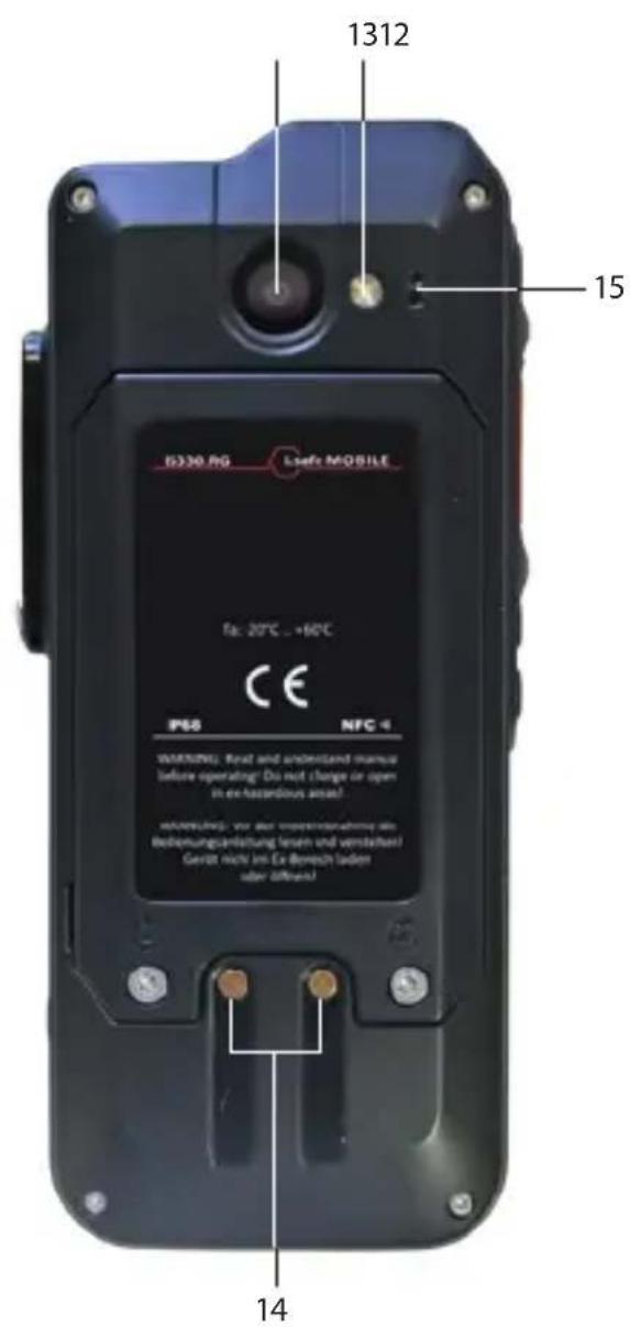
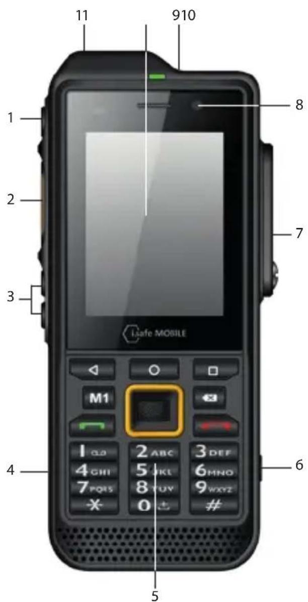
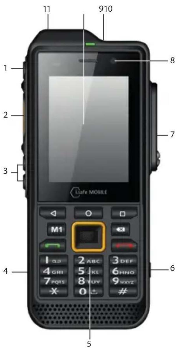
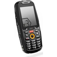
>DEVICE OVERVIEW/FUNCTIONS
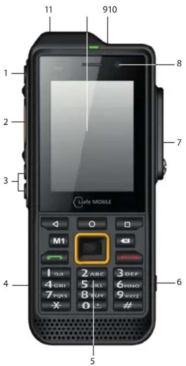
1) POWER KEY: A long press switches the device on/off. A short press switches the standby mode on/off.
2) SIDE KEY LEFT: Optional function - function can be assigned via Button App (system integrated).
3) LOUDNESS CONTROL: Volume up/Volume down.
4) USB INTERFACE: Connection for the USB-C Cable or for connection to other devices. Also see sections "Charging" and "Connecting approved accessories".
5>KEYPAD
6) FUNCTION KEY: Optional function - function can be assigned via Button App (system integrated).
7) 13-PIN ISM INTERFACE: Connection for approved accessories. Also see section "Connecting approved accessories".
8>FRONTCAMERA
9) SOS KEY: A long press of the SOS key sends an emergency call to a pre-saved emergency number (only in connection with a Lone Worker Protection app).
10> TOUCHSCREEN
11> EYELET: Eyelet for hand strap.
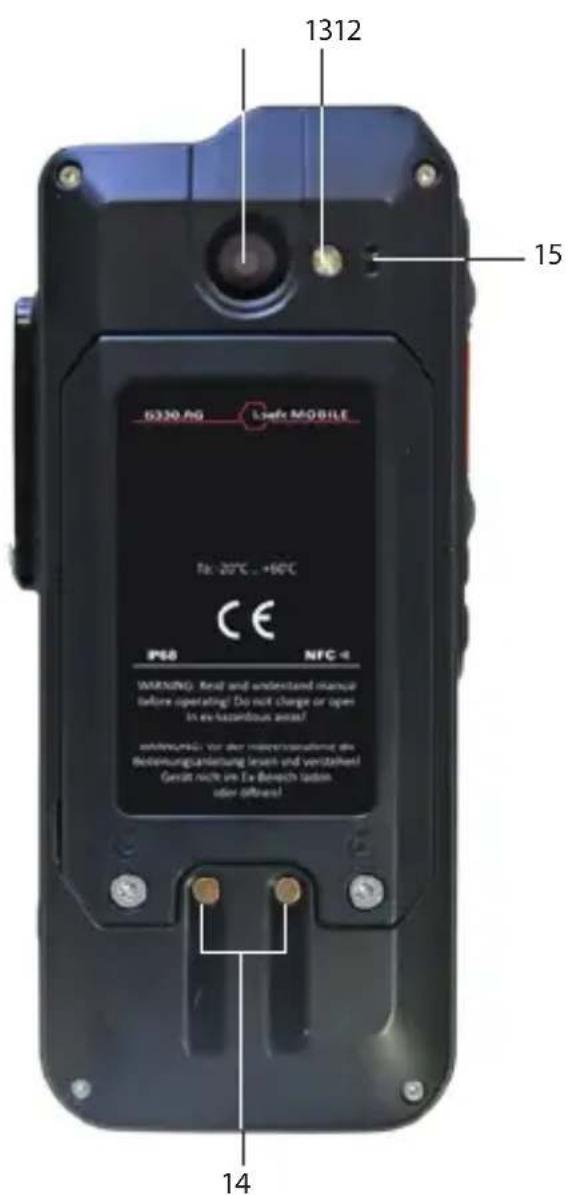
12>BACK CAMERA
13> LED FLASH
14> CHARGING CONTACT
15> MICROPHONE: Noise cancelling microphone/hands-free microphone.
> SAFETY
Read the "Safety" section of this Operating Manual carefully before using the device. If you do not follow these instructions or do not understand them, this could lead to death, severe injuries and damage to the device.
USER
Only trained users who have read and understood this Operating Manual may use this device.
USE OUTSIDE OF EXPLOSION HAZARDOUS AREAS
DANGER
Improper use can result in death or severe injuries!
» Do not use the device in explosion hazardous areas.
» Make sure that no gap can be seen between the two halves of the device.
» Do not use the device in places where its use is prohibited.
» Turn off the device in clinics or other medical facilities.
» Always keep a safety distance of at least 15 cm between the device and a pacemaker or hearing aid. The device can affect the functioning of medical devices such as pacemakers and hearing aids.
» When using the device while driving a motor vehicle, be sure to comply with applicable national laws.
» Make sure you prevent the user errors described in the section entitled "Possible User Errors".
» Only charge the device as described in the "Charging" section.
CAUTION
When using earphones or headsets at the maximum volume setting, you can damage your hearing.
» First set the volume control on the device to 50 % of the maximum volume.
» Gradually adjust the volume.
NOTICE
Incorrect use can damage the device.
» Only use accessories approved by i.safe MOBILE, as described in the section on "Connecting approved accessories".
» Protect the device and the Power Adapter from strong electrical magnetic fields as for example those emitted by induction cookers or microwave ovens, for example.
» Do not touch the display with sharp objects.
POSSIBLE USER ERRORS
DANGER
Improper use can result in death or severe injuries! Follow the instructions below:
» Do not modify the device structurally.
» Do not expose the device to high temperatures.
» Do not expose the device to strong UV radiation.
» Do not expose the device to processes with high electrical charges.
» Do not expose the device to aggressive acids or bases.
>SCOPE OF DELIVERY
Your device packaging contains the following:
1 x IS330.RG
1 x Battery
1 x Quick Start Manual
1 x Safety Instructions
1 x Display Protection Foil
1 x USB-C Cable
1 x Power Adapter universal (power supply unit and various country-specific adapters)
1 x Torx Screwdriver
1 x Display cleaning cloth
CELL BROADCAST
The device supports cell broadcast. Cell broadcast is a cellular service for sending messages to all recipients within a cell.
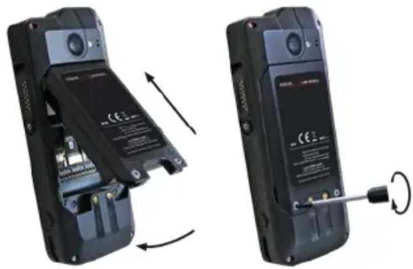
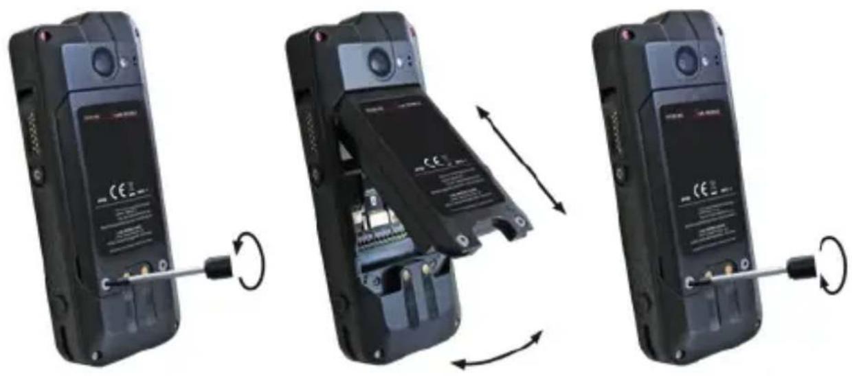
INSTALLING THE BATTERY
natural_image
Two black flip-flops with visible internal components and a close-up of the right showing a button (no text or symbols)» Place the battery in the battery compartment as shown.
» Hand-tighten the screws using the Torx Screwdriver provided.
» Check that the battery is seated correctly and securely.
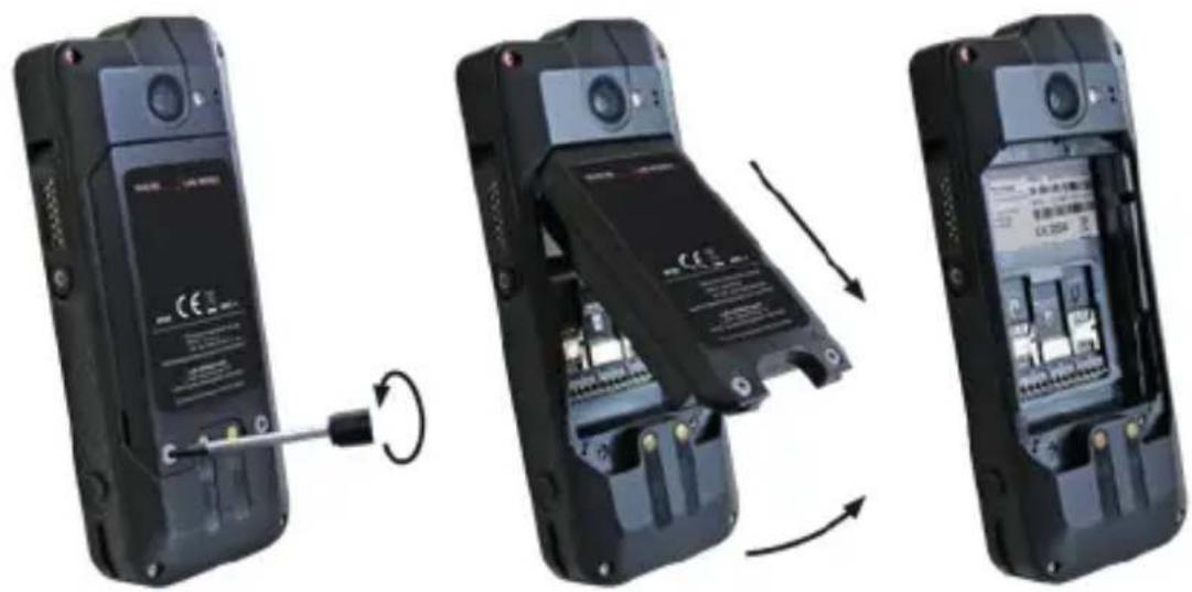
> INSERT/REMOVE SIM CARD
NOTICE
Proceeding incorrectly when inserting/removing the SIM card can damage the device and the SIM card. Switch off the device before inserting or removing a SIM card. Do not charge the device while inserting or removing a SIM card.
natural_image
Three-panel image showing a black flip phone with a screwdriver inserted, then open and then assembled (no visible text or symbols)» Loosen the screws on the battery using the Torx Screwdriver provided.
» Remove the battery from the battery compartment.
» Insert the SIM card into the slot. The device has two slots for one SIM card each. The slots are marked "SIM 1" and "SIM 2".
» If you have inserted two SIM cards, select a favorite card. Information on operating the device can be found at www.isafe-mobile.com/en/support/service under the menu item „FAQ“.
»Reinstall the battery. See section "Installing the battery".
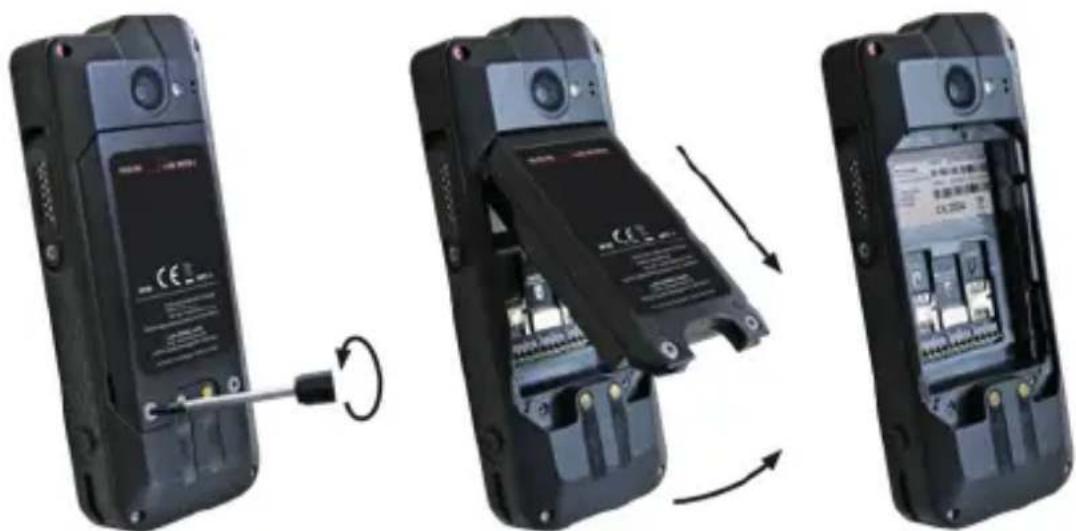
> INSERT/REMOVE microSD CARD
NOTICE
Proceeding incorrectly when inserting/removing the microSD card can damage the device and the microSD card. Switch off the device before inserting or removing a microSD card. Do not charge the device while inserting or removing a microSD card.
natural_image
Three-panel image showing a black flip phone with battery, showing internal components and a cable being inserted (no text or symbols visible)» Loosen the screws on the battery using the Torx Screwdriver provided.
» Remove the battery from the battery compartment.
» Insert the microSD card into the slot provided. The device has a slot for a microSD card up to 128 GB. The slot is marked "microSD".
»Reinstall the battery. See section "Installing the battery".
CHARGING
DANGER
Improper use can result in death or severe injuries! Do not charge the device in the vicinity of flammable substances.
NOTICE
Incorrect charging can cause damage to the device. Please note the following when charging:
» Only charge the device at ambient temperatures between +5 °C to +35 °C (+41 °F to +95 °F).
» Charge the device under dry indoor conditions only.
» Do not charge the device in environments dusty or humid.
Your device package contains a power supply unit, various country-specific adapters and an USB-C Cable.
» Connect the adapter suitable for your country to the power supply unit.
» Connect the USB-C Cable to the power supply unit.
» Connect the USB-C Cable to the USB interface of the device.
> SWITCHING ON/OFF
» Press and hold the on/off key for about 3 seconds.
»Enter the device or SIM PIN when the input dialog for the device or SIM PIN appears after switching on.
» Select the
>USING THE DEVICE
» When turning on the device for the first time, follow the instructions on the screen.
Further information on operating the device can be found at
www.isafe-mobile.com/en/support/service under the menu item "FAQ".
Detailed information on operating the Android operating system can be found at:
https://support.google.com/android
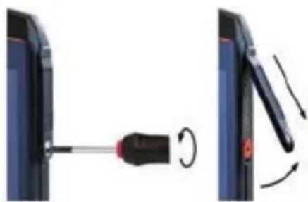
CONNECTING APPROVED ACCESSORIES
» Only connect accessories approved by i.safe MOBILE to the device. Accessories approved by i.safe MOBILE can be found at www.isafe-mobile.com/en/products
Approved accessories can be connected to any 13-pin ISM interface and to the USB interface.
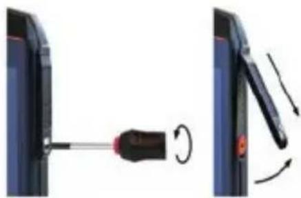
13-PIN ISM INTERFACE
natural_image
Diagram showing a screwdriver inserted into a device, with motion arrows indicating rotation (no text or symbols present)» Loosen the screw on the 13-pin ISM interface cover using the Screwdriver provided and remove the cover as shown. The Screwdriver is included in the accessory package.
natural_image
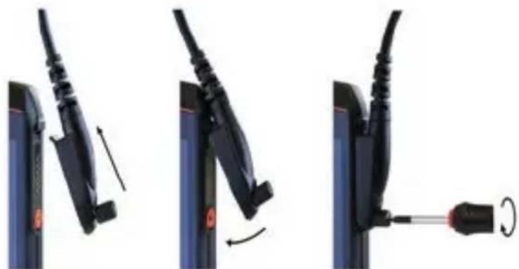
Three-step diagram showing cable fastening and screwdriver insertion (no text or symbols)» Connect the plug of the approved accessory to the 13-pin ISM interface as shown.
» Hand-tighten the screws using the Screwdriver provided.
» Check that the plug is seated correctly and securely.
USB INTERFACE
The USB interface is used for charging and data transfer.
»Connect approved accessories or other devices to the USB interface only by using the USB-C Cable.
CHANGING THE BATTERY
An approved replacement battery can be found on the website www.isafe-mobile.com/en/products
natural_image
Three-panel diagram showing a device being opened, with arrows indicating rotation and assembly (no text or symbols present)» Loosen the screws on the battery using the Torx Screwdriver provided.
» Remove the battery from the battery compartment as shown.
» Place the approved replacement battery in the battery compartment as shown.
» Hand-tighten the screws using the Torx Screwdriver provided.
» Check that the battery is seated correctly and securely.
POSSIBLE DEVICE PROBLEMS
You can find information on possible device problems and how to rectify them at www.isafe-mobile.com/en/support/service under the menu item "FAQ".
If you have any further questions, please contact the i.safe MOBILE repair service at www.isafe-mobile.com/en/support/service
MAINTENANCE/REPAIR
The device itself has no serviceable parts.
WARNING
Incorrect repairs present a risk of explosion or fire, which can result in death or severe injuries! Do not open the device or carry out any repairs yourself.
» Contact the i.safe MOBILE repair service at www.isafe-mobile.com/en/support/service if the device is not working normally, if the device needs to be repaired or if a replacement part is required.
RETURN SHIPMENT
Contact the i.safe MOBILE repair service at www.isafe-mobile.com/en/support/service
DISTRIBUTION PARTNER
You can find the specialist distribution partner responsible for your country at www.isafe-mobile.com/en/contact
CLEANING
NOTICE
Incorrect cleaning can cause damage to the device. Please note the following when cleaning:
» Turn off the device before cleaning.
» Do not charge the device while cleaning.
» Do not use chemical agents for cleaning.
» Clean the device and the Power Adapter with a soft, moistened antistatic cloth.
» Clean the display screen regularly with a soft, antistatic cloth.
>STORAGE
NOTICE
Incorrect storage can cause damage to the device. Store the device at ambient temperatures between +5 °C to +35 °C (+41 °F to +95 °F) and a humidity between 10 % to 60 %.
RECYCLING
NOTICE
Incorrect disposal of electronic products, batteries and packaging material puts the environment at risk. Please note the following when disposing of items:
» DO NOT throw away batteries with household waste.
» Always dispose electronic products, batteries and packaging material at the appropriate collection points. This way, you prevent uncontrolled waste disposal and promote the recycling of material resources.
You can obtain further information from regional waste disposal companies, state authorities or the i.safe MOBILE service centre responsible for your country or region at www.isafe-mobile.com/en/support/service
TRADEMARKS
i.safe MOBILE and the i.safe MOBILE logo are registered trademarks of the i.safe MOBILE GmbH.
EEA Version: Comes with the Google™ app and Google Chrome™
Google and Google Play are trademarks of Google LLC.
All other trademarks and copyrights are the properties of their respective owners.
DEUTSCH
natural_image
Two black flip-flops with visible internal components and a close-up of the right showing a button (no text or symbols)natural_image
Three-panel image showing a black flip phone with a cable being inserted, then assembled and then closed (no visible text or symbols)natural_image
Three-panel image showing a black flip phone with a cable inserted, then open and then assembled (no visible text or symbols)natural_image
Diagram showing a screwdriver being inserted into a device, with motion arrows indicating rotation (no text or symbols present)natural_image
Three-step diagram showing cable fastening and mounting mechanism (no text or symbols)natural_image
Three-panel diagram showing a black flip phone with battery, internal circuit board, and cable being inserted (no text or symbols)www.isafe-mobile.com/en/support/downloads
PROHLÁŠENÍ FCC/IC
www.isafe-mobile.com/en/support/downloads
PŘEHLED O ZAŘÍZENÍ/FUNKCÍCH
natural_image
Two black flip-flops with visible internal components and a close-up of the right showing a button (no text or symbols)natural_image
Three-panel image showing a black flip phone with a screwdriver inserted, then assembled and then assembled (no visible text or symbols)natural_image
Three-panel image showing a black flip phone with battery, switch, and internal circuitry (no visible text or symbols)natural_image
Diagram showing a screwdriver being inserted into a device, with motion arrows indicating rotation (no text or symbols present)natural_image
Three-step diagram showing cable fastening and fastening process (no text or symbols)natural_image
Three-panel diagram showing a black flip phone with battery, showing internal circuitry and rotation arrows (no text or symbols)natural_image
Two black flip-flops with internal components, shown from external to internal rotation (no text or symbols visible)natural_image
Three-panel diagram showing a mobile phone's internal components being connected, with no visible text or symbols.natural_image
Three-panel image showing a mobile phone's internal components being connected, with one part being inserted and the others showing disassembly (no text or symbols visible)natural_image
Diagram showing a screwdriver being inserted into a device, with motion arrows indicating rotation (no text or symbols present)natural_image
Three-step diagram showing cable fastening and screwdriver insertion (no text or symbols)natural_image
Three-step diagram showing a device being opened, with arrows indicating rotation and assembly (no text or symbols present)natural_image
Two black flip-flops with internal components, shown from external to internal rotation (no text or symbols visible)natural_image
Three-panel image showing a black flip phone with a screwdriver inserted, then open and then assembled (no visible text or symbols)natural_image
Three-panel image showing a mobile phone's internal components being adjusted, with one part being inserted and the others showing disassembly (no text or symbols visible)https://support.google.com/android
natural_image
Diagram showing a screwdriver being inserted into a device, with motion arrows indicating rotation (no text or symbols present)natural_image
Three-step diagram showing cable fastening and screwdriver insertion (no text or symbols)natural_image
Three-panel diagram showing a black flip phone with battery, internal circuit board, and external switch (no text or symbols)natural_image
Two black flip-flops with visible internal components and a close-up of the right showing a button (no text or symbols)natural_image
Three-panel image showing a black flip phone with a screwdriver inserted, then open and then assembled (no visible text or symbols)natural_image
Three-panel image showing a black flip phone with a screwdriver inserted, then open and then closed (no visible text or symbols)https://support.google.com/android
HYVÄKSYTTYJEN LISÄLAITTEIDEN LIITTÄMINEN
natural_image
Diagram showing a screwdriver being inserted into a device, with motion arrows indicating rotation (no text or symbols present)natural_image
Three-step diagram showing cable fastening and mounting mechanism (no text or symbols)natural_image
Three-step diagram showing a device being switched to a battery, with no visible text or symbols.DÉCLARATION DE CONFORMITÉ UE
natural_image
Two black flip-flops with visible internal components and a close-up of the right showing a button (no text or symbols)natural_image
Three-panel image showing a black flip phone with internal components and a tool inserted, illustrating the process of battery disassembly (no text or symbols visible)natural_image
Three-panel image showing a black flip phone with a screwdriver inserted, then assembled and then closed (no visible text or symbols)MISE EN MARCHE/ARRÊT
INTERFACE 13-PIN ISM
natural_image
Diagram showing a screwdriver inserted into a device, with rotation arrows indicating motion (no text or symbols)natural_image
Three-step diagram showing cable installation steps: wire insertion, switch press, and end cap assembly (no text or symbols)natural_image
Three-panel diagram showing a device being opened, with arrows indicating rotation and assembly (no text or symbols present)natural_image
Two black flip-flops with internal components, shown from external to internal rotation (no text or symbols visible)natural_image
Three-panel image showing a black flip phone with battery, showing internal circuitry and battery casing (no text or symbols visible)natural_image
Three-panel image showing a mobile phone's internal components being inserted, with one part being adjusted and the others showing disassembly (no text or symbols visible)natural_image
Diagram showing a screwdriver inserted into a device, with rotation arrows indicating motion (no text or symbols)natural_image
Three-step diagram showing cable fastening process: valve insertion, switch press, and screwdriver assembly (no text or symbols)natural_image
Three-step diagram showing a device being switched to a battery, with no visible text or symbols.www.isafe-mobile.com/en/support/service
www.isafe-mobile.com/en/support/downloads
DICHIARAZIONE FCC/IC
www.isafe-mobile.com/en/support/downloads
PANORAMICA/FUNZIONI DEL DISPOSITIVO


USO FUORI DALLE AREE A RISCHIO DI ESPLOSIONE
PERICOLO
natural_image
Two black flip-flops with internal components, shown from external to internal rotation (no text or symbols visible)natural_image
Three-panel image showing a black flip phone with battery, showing internal circuitry and battery casing (no text or symbols visible)natural_image
Three-panel image showing a device being inserted into a battery, with no visible text or symbols on the main components.natural_image
Diagram showing a screwdriver inserted into a device, with rotation arrows indicating motion (no text or symbols)natural_image
Three-step diagram showing cable fastening and disassembly process (no text or symbols)natural_image
Three-panel diagram showing a black flip phone with battery, internal circuit board, and cable being inserted (no text or symbols visible)natural_image
Two black flip-flops with internal components, shown from external to internal rotation (no text or symbols visible)natural_image
Three-panel image showing a black flip phone with a USB cable being inserted, then assembled into an open battery pack (no visible text or symbols)natural_image
Three-panel image showing a black flip phone with a cable being inserted, then assembled into an open case (no visible text or symbols)natural_image
Diagram showing a screwdriver inserted into a device, with rotation arrows indicating motion (no text or symbols)natural_image
Three-step diagram showing cable fastening process: left panel with cable attachment, right panel with screwdriver inserted (no text or symbols)natural_image
Three-panel diagram showing a device being opened, with arrows indicating rotation and assembly (no text or symbols present)www.isafe-mobile.com/en/support/downloads
FCC/IC UTTALELSE
FCC/IC-erklæringen finner du på www.isafe-mobile.com/en/support/downloads
ENHETSOVERSIKT/FUNKSJONER

natural_image
Two black flip-flops with internal components, shown from external to internal rotation (no text or symbols visible)natural_image
Three-panel image showing a black flip phone with a screwdriver inserted, then open and then assembled (no visible text or symbols)natural_image
Three-panel image showing a black flip phone with battery, cable, and internal components, arranged in sequence (no text or symbols visible)natural_image
Diagram showing a screwdriver being inserted into a device, with motion arrows indicating rotation (no text or symbols present)natural_image
Three-step diagram showing cable fastening and screwdriver insertion (no text or symbols)»Koble til pluggen for det godkjente tilbehøret til 13-pin ISM-grensesnittet som vist.
»Stram skruene for hånd med den medfølgende skrutrekkeren.
» Kontroller at pluggen sitter korrekt og sikkert.
USB-GRENSESNITT
natural_image
Three-panel diagram showing a black flip phone with battery, internal circuit, and external switch mechanism (no text or symbols)VEDLIKEHOLD/REPARASJON
natural_image
Two black flip-flops with internal components, shown from external to internal rotation (no text or symbols visible)natural_image
Three-panel image showing a black flip phone with a screwdriver inserted, then open and then assembled (no visible text or symbols)natural_image
Three-panel image showing a black flip phone with a cable being inserted, then assembled and then closed (no visible text or symbols)natural_image
Diagram showing a screwdriver being inserted into a device, with rotation arrows indicating motion (no text or symbols)natural_image
Three-step diagram showing cable fastening process: valve insertion, switch press, and screwdriver assembly (no text or symbols)natural_image
Three-step diagram showing the internal mechanism of a mobile phone's battery, with no visible text or symbols.natural_image
Two black flip-flops with visible internal components and a close-up of the interior showing a battery and switch (no text or symbols)» Posicione a bateria no compartimento de bateria conforme exibido.
» Aperte os parafusos usando a chave Torx fornecida.
» Verifique se a bateria está encaixada corretamente e com firmeza.
>INSERIR/REMOVER CARTÃO SIM
OBSERVAÇÃO
natural_image
Three-panel image showing a black flip phone with a USB cable being inserted, then assembled and then closed (no visible text or symbols)» Solte os parafusos da bateria utilizando a chave Torx fornecida.
»Remova a bateria do compartimento de bateria.
natural_image
Three-panel image showing a mobile phone's internal components being inserted, with one part being adjusted and the others showing disassembly (no text or symbols visible)INTERFACE 13-PIN ISM

natural_image
Diagram showing a screwdriver being inserted into a device, with motion arrows indicating rotation (no text or symbols present)natural_image
Three-step diagram showing cable fastening process: left panel with cable attachment, right panel with cable being inserted (no text or symbols)natural_image
Three-panel diagram showing a black flip phone with battery, internal circuit board, and cable being inserted (no text or symbols)» Solte os parafusos da bateria utilizando a chave Torx fornecida.
» Remova a bateria do compartimento de bateria, conforme exibido.
» Posicione a bateria substituta aprovada no compartimento de bateria, conforme exibido.
» Aperte os parafusos usando a chave Torx fornecida.
» Verifique se a bateria está encaixada corretamente e com firmeza.
POSSÍVEIS PROBLEMAS DO DISPOSITIVO
natural_image
Two black flip-flops with visible internal components and battery modules, shown from external to internal states (no text or symbols)» Placera batteriet i batteriutrymmet enligt bild.
natural_image
Three-panel image showing a black flip phone with a cable being inserted, then assembled and then closed (no visible text or symbols)natural_image
Three-panel image showing a black flip phone with battery, showing internal components and a close-up of its internal structure (no text or symbols visible)natural_image
Diagram showing a screwdriver being inserted into a device, with motion arrows indicating rotation (no text or symbols present)natural_image
Three-step diagram showing cable fastening and screwdriver insertion (no text or symbols)natural_image
Three-panel diagram showing a device being opened, with arrows indicating rotation and component movement (no text or symbols)www.isafe-mobile.com/en/support/service
www.isafe-mobile.com/en/support/downloads
ЗАЯВЛЕНИЕ FCC / IC
www.isafe-mobile.com/en/support/downloads
natural_image
Two black flip-flops with visible internal components and a close-up of the interior showing a button (no text or symbols)natural_image
Three-panel image showing a black flip phone with a cable being inserted, then assembled and then closed (no visible text or symbols)natural_image
Three-panel image showing a black flip phone with a screwdriver inserted, then open and then assembled (no visible text or symbols)natural_image
Diagram showing a screwdriver being inserted into a device, with motion arrows indicating rotation (no text or symbols present)natural_image
Three-step diagram showing cable fastening and fastening process (no text or symbols)natural_image
Three-panel diagram showing a black flip phone with battery, internal circuit, and external switch, each with a circular arrow indicating rotation (no text or symbols present)natural_image
Two black flip-flops with visible internal components and a circular arrow indicating rotation (no text or symbols)natural_image
Three-panel image showing a black flip phone with a USB cable being inserted, then assembled and then closed (no visible text or symbols)natural_image
Three-panel image showing a black flip phone with battery, showing internal circuitry and battery casing (no text or symbols visible)natural_image
Diagram showing a screwdriver inserted into a device, with rotation arrows indicating motion (no text or symbols)natural_image
Three-step diagram showing cable fastening and disassembly process (no text or symbols)natural_image
Three-step diagram showing a device being switched to a battery, with arrows indicating the process (no text or symbols present)natural_image
Two black flip-flops with visible internal components and a circular arrow indicating rotation (no text or symbols)natural_image
Three-panel image showing a black flip phone with a USB cable being inserted, then assembled and then closed (no visible text or symbols)natural_image
Three-panel image showing a black flip phone with battery, cable, and internal components, arranged in sequence (no text or symbols visible)natural_image
Diagram showing a screwdriver being inserted into a device, with motion arrows indicating rotation (no text or symbols present)natural_image
Three-step diagram showing cable fastening and screwdriver insertion (no text or symbols)natural_image
Three-step diagram showing a device being opened into a device, with arrows indicating the process (no text or symbols present)natural_image
Two black flip-flops with visible internal components and a close-up of the right showing a button (no text or symbols)如图所示,将电池放入电池仓中。
》使用随附的内梅花螺丝刀手动拧紧螺钉。
》检查电池已正确、牢固放置。
插入/移除 SIM 卡
注意
natural_image
Three-panel image showing a black flip phone with a screwdriver inserted, then assembled and then assembled (no visible text or symbols)natural_image
Three-panel image showing a black flip phone with battery, showing internal circuitry and battery casing (no text or symbols visible)natural_image
Diagram showing a screwdriver inserted into a device, with rotation arrows indicating motion (no text or symbols)natural_image
Three-step diagram showing cable fastening and screwdriver insertion (no text or symbols)natural_image
Three-step diagram showing a device being opened into a device, with arrows indicating the process (no text or symbols present)www.isafe-mobile.com/cn/support/downloads
www.isafe-mobile.com/en/support/downloads
www.isafe-mobile.com/en/support/service
www.isafe-mobile.com/en/support/downloads
natural_image
Two black flip-flops with visible battery labels and a screwdriver inserted, shown from different angles (no text or symbols on the devices themselves)natural_image
Three views of a black mobile phone showing internal components and battery modules, with a close-up of the battery being inserted (no text or symbols visible)."SIM 2,, & "SIM 1,,
natural_image
Three-panel image showing a black flip phone with internal components and a close-up of its internal structure, illustrating the process of battery disassembly (no text or symbols visible)natural_image
Two-step diagram showing a switch being inserted into a device, with no visible text or symbols.natural_image
Three-step diagram showing a cable being inserted into a device, with no visible text or symbols.natural_image
Three-step diagram showing a device being opened, with arrows indicating rotation and assembly (no text or symbols present)natural_image
A plain gray background with a single horizontal red line at the bottom (no text or symbols)CONTACT/SERVICE CENTRE
FOR FURTHER QUESTIONS PLEASE CONTACT OUR SERVICE CENTRE:
» i.safe MOBILE GmbH, i_Park Tauberfranken 10, 97922 Lauda-Koenigshofen, Germany
» support@isafe-mobile.com
» https://support.isafe-mobile.com

natural_image
Nighttime exterior view of a large industrial chemical plant with illuminated towers and piping (no visible text or signage)WWW.ISAFE-MOBILE.COM

- CONTENTS
- ENGLISH
- >READ AND UNDERSTAND THE INSTRUCTIONS
- PROTECT YOUR LIFE AND READ THE OPERATING MANUAL
- INTENDED USE
- WARRANTY
- EU DECLARATION OF CONFORMITY
- FCC/IC STATEMENT
- >DEVICE OVERVIEW/FUNCTIONS
- > SAFETY
- USER
- USE OUTSIDE OF EXPLOSION HAZARDOUS AREAS
- DANGER
- CAUTION
- NOTICE
- POSSIBLE USER ERRORS
- >SCOPE OF DELIVERY
- CELL BROADCAST
- INSTALLING THE BATTERY
- > INSERT/REMOVE SIM CARD
- > INSERT/REMOVE microSD CARD
- CHARGING
- > SWITCHING ON/OFF
- >USING THE DEVICE
- CONNECTING APPROVED ACCESSORIES
- 13-PIN ISM INTERFACE
- USB INTERFACE
- CHANGING THE BATTERY
- POSSIBLE DEVICE PROBLEMS
- MAINTENANCE/REPAIR
- WARNING
- RETURN SHIPMENT
- DISTRIBUTION PARTNER
- CLEANING
- >STORAGE
- RECYCLING
- TRADEMARKS
- DEUTSCH
- PROHLÁŠENÍ FCC/IC
- HYVÄKSYTTYJEN LISÄLAITTEIDEN LIITTÄMINEN
- DÉCLARATION DE CONFORMITÉ UE
- MISE EN MARCHE/ARRÊT
- INTERFACE 13-PIN ISM
- DICHIARAZIONE FCC/IC
- PANORAMICA/FUNZIONI DEL DISPOSITIVO
- USO FUORI DALLE AREE A RISCHIO DI ESPLOSIONE
- PERICOLO
- FCC/IC UTTALELSE
- USB-GRENSESNITT
- VEDLIKEHOLD/REPARASJON
- >INSERIR/REMOVER CARTÃO SIM
- OBSERVAÇÃO
- POSSÍVEIS PROBLEMAS DO DISPOSITIVO
- ЗАЯВЛЕНИЕ FCC / IC
- 插入/移除 SIM 卡
- 注意
- CONTACT/SERVICE CENTRE
Brand : i.safe Mobile
Model : IS330.RG
Category : Mobile Phone