SC550 CYL - Floor cleaner NILFISK - Free user manual and instructions
Find the device manual for free SC550 CYL NILFISK in PDF.

| Brand and model | Nilfisk SC550 CYL |
| Product type | Scrubber for smooth and hard floors (washing and drying) |
| Available models | SC550 53D, SC550 61D, SC550 51C, SC550 51R |
| Weight (with Li-ion 50Ah battery) | 173 to 183 kg depending on model |
| Weight without battery and empty tanks | 105 to 115 kg depending on model |
| Battery | Li-ion 24V 50Ah (1 piece) or 24V 64Ah (option) |
| Autonomy (ECO mode, 50Ah battery) | 3.4 to 3.8 hours depending on model |
| Autonomy (normal mode, 50Ah battery) | 2.8 to 3.6 hours depending on model |
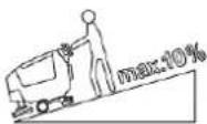
| Maximum operating slope | 10% (max 20 continuous meters) |
| Sound pressure level (normal mode) | 63-65 dB(A) depending on model |
| Washing system | Disc brushes, cylindrical brushes, or REV system (depending on version) |
| Solution tank | With EcoFlex system (integrated detergent) or without |
| Recovery tank | With automatic float shut-off |
| Squeegee | Adjustable, with front and rear blades |
| Available brush types | 46 GRIT, 80 GRIT, 180 GRIT, 240 GRIT, 500 GRIT, PROLENE, PROLITE, UNION MIX |
| Additional functions | Extra power (60s), silent mode, preset modes, REV system (increased pressure) |
| Protection rating | IP X4 |
| Electrical protection class | III |
| Daily maintenance | Clean squeegee, brush, tank, suction grid, solution filter |
| Periodic maintenance | Check blades, motor brushes, REV dampers (every 6 months / 1 year) |
| Safety | Emergency stop button, electromagnetic brake, automatic stop after 5 minutes of inactivity |
| Recyclable materials | Aluminum, steel, polyethylene, cables (variable recycling rate) |
Frequently Asked Questions - SC550 CYL NILFISK
User questions about SC550 CYL NILFISK
0 question about this device. Answer the ones you know or ask your own.
Ask a new question about this device
Download the instructions for your Floor cleaner in PDF format for free! Find your manual SC550 CYL - NILFISK and take your electronic device back in hand. On this page are published all the documents necessary for the use of your device. SC550 CYL by NILFISK.
USER MANUAL SC550 CYL NILFISK
natural_image
Line drawing of a cleaning or cleaning machine with no visible text or symbols on the device body| GB | ENGLISH | QUICK START GUIDE......1-16 |
| BG | БЪЛГАРСКИ | КРАТКО РЪКОВОДСТВО......17-32 |
| CN | ČESKY | RYCHLÁ PŘÍRUČKA......33-48 |
| DE | DEUTSCH | SCHNELLSTARTANLEITUNG......49-64 |
| DK | DANSK | LYNVEJLEDNING TIL HURTIG OPSTART ......65-80 |
| GR | ЕЛАННИКА | ОДНГОЗ ГРНГОРНЗ ЕККИННЗНЗ......81-96 |
| ES | ESPAÑOL | GUÍA RÁPIDA DE UTILIZACIÓN......97-112 |
| ET | EESTI | KIIRJUHEND ......113-128 |
| FI | SUOMI | PIKAKÄYNNISTYSOPAS ......129-144 |
| FR | FRANÇAIS | GUIDE DE DÉMARRAGE RAPIDE......145-160 |
| FR | HRVATSKI | PRIRUČNIK ZA BRZI POČETAK RADA......161-176 |
| HU | MAGYAR | GYORS ÜZEMBE HELYEZÉSI ÚTMUTATÓ ......177-192 |
| IT | ITALIANO ORIGINAL INSTRUCTIONS | GUIDA RAPIDA ALL'USO ......193-208 |
| LT | LIETUVIŠKAI | GREITOJO PALEIDIMO VADOVAS......209-224 |
| LV | LATVIEŠU VALODA | PAMATA LIETOŠANAS INSTRUKCIJA......225-240 |
| NL | NEDERLANDS | SNELSTARTGIDS......241-256 |
| NO | NORSK | HURTIGSTARTVEILEDNING ......257-272 |
| PL | POLSKI | SKRÓCONA INSTRUKCJA URUCHAMIANIA ....273-288 |
| PT | PORTUGUÊS | GUIA DE INÍCIO RÁPIDO......289-304 |
| RO | ROMÂNĂ | GHID PENTRU PORNIRE RAPIDĂ ......305-320 |
| RU | PYССКИЙ | РУКОВОДСТВО ПО НАЧАЛУ РАБОТЫ ......321-336 |
| SK | SLOVENSKY | PRÍRUČKA SO STRUČNÝM NÁVODOM ......337-352 |
| SL | SLOVENŠČINA | HITRI VODIČ......353-368 |
| SV | SVENSK | SNABBSTARTSGUIDE ......369-384 |
| TR | TÜRKÇE | HIZLI BAŞLANGIÇ KILAVUZU......385-400 |
| NILFISK | EU / UE / EL / EC / EE / ES / EÚ / AB / EG | ||
| Declaration of Conformity | Декларация за съответствие | Conformiteitsverklaring | |
| Prohlášení o shodě | Δήλωση συμμόρφωσης | Declaração de conformidade | |
| Konformitätserklärung | Megfelelősségi nyllatkozat | Deklaracja zgodności | |
| Overensstemmelseserklæring | Izjava o sukladnosti | Declaratie de conformitate | |
| Declaración de conformidad | Dichiarazione di conformità | Försäkran om överensstämmelse | |
| Vastavusdeklaratsioon | Atitikties deklaracija | Vyhlásenie o zhode | |
| Déclaration de conformité | Atbilstības deklarācija | Izjava o skladnosti | |
| Vaatimustenmukalsuusvakuutus | Samsvarserklæring | Uygunluk beyani | |
Manufacturer / Výrobce / Hersteller / Fabrikant / Fabricante / Kατασκευαστής / Gyártó / Proizvođač / Fabbricante / Gamintojas / Ražotājs / Produsent / Fabrikant Nilfisk A/S, Marmorvej 8 / Fabricante / Producent / Produčator / Tillverkaren / Výrobca / Proizvajalec/ Üretici firma: DK-2100 Copenhagen ∅, DENMARK
| Product / Produkt / Producto, Toode, Produit, Tuote/ Προϊόν/ Termék / Proizvod / Prodotto / Produktas / Produkts /Artikel / Produtos / Produs / Izdelek / Ürün | SC550 |
| Description / Popis / Beschreibung / Beskrivelse / Descripción /Kirjeldus / La description / Kuvaus / Описание / Пεριγραφή / Leirás /Opis / Descrizione / Aprašymas / Apraksts / Beschrijving / Descrição /Descriere / Beskrivning / Popis / Açıklama | FC - Floor Scrubber/Sweeper - BatteryCharging mode 100-240V 50-60Hz; Workingmode 24V DC, IPX4 |

We, Nilfisk hereby declare under our sole responsibility, that the above-mentioned product(s) is/are in conformity with the following directives and standards.

Authorized to compile Technical File and signatory:
Warner Guo, VP R&D, Head of Competence Center APAC • R&D
Aug 13, 2024
Weilma (Warner) Guo
INTRODUCTION

WARNING!
For general information or other detail not included in this Guide, see the Instructions for Use Manual by scan the QR code on the right to obtain it.

NOTE
The numbers in brackets refer to the components shown in Machine Description chapter.

GUIDE PURPOSE AND CONTENTS
The purpose of this Quick Start Guide is to provide the operator with all basic information to use the machine properly. For information about technical characteristics, operation, machine inactivity, maintenance, spare parts and safety conditions, see the Instruction for Use Manual by scan the QR code to obtain it. Before performing any procedure on the machine, the operators and qualified technicians must read the Instructions for Use Manual by scan the QR code to obtain it. Contact Nilfisk in case of doubts concerning the interpretation of the instructions and for any further information.
HOW TO KEEP THIS GUIDE
This Quick Start Guide must be kept near the machine, inside an adequate case, away from liquids and other substances that can cause damage to it.

NOTE
It is recommended to print a copy of the Instructions for Use Manual by scan the QR code to obtain it and make it available for the operator, together with this Quick Start Guide.
DECLARATION OF CONFORMITY
The Declaration of Conformity, supplied with the machine, certifies the machine conformity with the law in force.

NOTE
Two copies of the original declaration of conformity are provided together with the machine documentation.
IDENTIFICATION DATA
The machine serial number and model name are marked on the plate (14).
Year of production (Date code: A17 means January 2017) and model number are marked on the same plate.
This information is useful when requiring machine spare parts. Use the following table to write down the machine identification data.
Model
Model number
Serial number
The scrubber-dryer is used to clean (scrubbing and drying) smooth and solid floors, in commercial or industrial environment, under safe operation conditions by a qualified operator.
The scrubber-dryer cannot be used for fitted carpet and carpet cleaning.
CONVENTIONS
Forward, backward, front, rear, left or right are intended with reference to the operator's position, that is to say in driving position with the hands on the handlebar (15).

SAFETY
The following symbols indicate potentially dangerous situations. Always read this information carefully and take all necessary precautions to safeguard people and property. The operator's cooperation is essential in order to prevent injury. No accident prevention program is effective without the total cooperation of the person responsible for the machine operation. Most of the accidents that may occur in a factory, while working or moving around, are caused by failure to comply with the simplest rules for exercising prudence. A careful and prudent operator is the best guarantee against accidents and is essential for successful completion of any prevention program.
VISIBLE SYMBOLS ON THE MACHINE
WARNING!
Read all the instructions carefully before performing any operation on the machine.
WARNING!
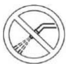
Do not wash the machine with direct or pressurized water jets.
WARNING!
Do not use the machine on slopes with a gradient exceeding that is defined in the specification.
SYMBOLS THAT APPEAR ON THIS MANUAL

DANGER!
It indicates a dangerous situation with risk of death for the operator.

WARNING!
It indicates a potential risk of injury for people.

CAUTION!
It indicates a caution or a remark related to important or useful functions. Pay attention to the paragraphs marked by this symbol.

NOTE
It indicates a remark related to important or useful functions.

CONSULTATION
It indicates the necessity to refer to the Instruction for Use manual before performing any procedure.
GENERAL INSTRUCTIONS
Specific warnings and cautions to inform about potential damages to people and machine are shown below.

DANGER!
Before performing any maintenance, repair, cleaning or replacement procedure, turn off the machine and disconnect the battery connector. This machine must be used by properly trained operators only. Do not operate the machine near toxic, dangerous, flammable and/or explosive powders, liquids or vapors. This machine is not suitable for collecting dangerous powders.

WARNING!
- Carefully read all the instructions before performing any maintenance/repair procedure.
Always use the battery charger supplied with the machine or the original spare part. Firstly, turn off the machine. And then disconnect the battery pack from the appliance before making any adjustments, changing accessories, or storing appliance. Such preventive safety measures reduce the risk of starting the appliance accidentally.
- Do not use the machine if the battery charger cable or plug is damaged. If the machine is not working as it should, has been damaged, left outdoors or dropped into water, return it to the Service Center.
- To reduce the risk of fire, electric shock, or injury, before performing any maintenance procedure, disconnect the battery charger cable from the electrical mains.
- Always protect the machine against the sun, rain and bad weather, both under operation and inactivity condition. This machine must be used and stored indoors in dry conditions, it must not be used or kept outdoors in wet conditions.
- Do not use the machine on slopes with a gradient exceeding that is defined in the specification.
- This machine is not intended for use by persons (including children) with reduced physical, sensory or mental capabilities, or lack of experience and knowledge.
- Children should be supervised to ensure that they do not play with the machine.
- When using floor cleaning detergents, follow the instructions on the labels of the detergent bottles.
- To handle floor cleaning detergents, wear suitable gloves and protections.
- The machine must be disposed of properly, because of the presence of toxic-harmful materials (batteries, etc.), which are subject to standards that require disposal in special centres (see Scrapping chapter).
- This machine is intended for commercial use, for example in hotels, schools, hospitals, factories, shops, offices and rental businesses.
- Operators shall be adequately instructed on the use of these machines.
Do not look at the laser beams used by the machine. Permanent eye damage could result. Lasers are eye-safe if viewed briefly, such as to determine that they are functioning. Do not look directly into lasers or stare at them without wearing protective laser safety glasses.
- Use only the brushes supplied with the machine or those specified in the Instructions for Use Manual. Using other brushes could reduce safety.
In order to prevent unauthorized use of the machine, the power source shall be switched off or locked, for example by turn off the machine.
- Machines left unattended shall be secured against unintentional movement.
- In case of machine malfunctions, ensure that these are not due to lack of maintenance. If necessary, request assistance from the authorised personnel or from an authorised Service Center.
Nilfisk products approved against 61000-6-8 shall include below statements in the manual:
This equipment meets the requirements for commercial and light-industrial locations when professionally installed and maintained.
Installation and maintenance shall be performed by an EMC professional.
The professional installer shall evaluate the EMC situation before installation, if the equipment is installed closer than 30 m to a residential location.
Caution: This equipment is not intended for use in residential locations and will not guarantee to provide adequate protection to radio reception in such locations.
TECHNICAL DATA
| Model | SC550 53D | SC550 61D | SC550 51C | SC550 51R |
| Sound pressure level at workstation(ISO 11201, ISO 4871, EN 60335-2-72) (LpA)(dB(A)) Normal mode / Silent Mode | 63 ± 3 / 56 ± 3 | 65 ± 3 / 61 ± 3 | 65 ± 3 / 59 ± 3 | 65 ± 3 / 62 ± 3 |
| Machine sound power level (ISO 3744,ISO 4871, EN 60335-2-72) (LwA) (dB(A))Normal mode / Silent Mode | 75 / 71 | 80 / 75 | 77 / 76 | 78 / 77 |
| Vibration level at the operator's arms(ISO 5349-1, EN 60335-2-72) | < 2.5 m/s2 | |||
| Maximum gradient when working (%)(*1) | 10 | |||
| IP protection class | X4 | |||
| Protection class (electric) | III | |||
| Li-ion Standard batteries | 24V 50Ah x 1 | |||
| Rated power input (W) (*) | 830 | 630 | 680 | 560 |
| Li-ion 50Ah Max. running time (hour) (*)ECO mode (50Ah 1pcs) | 3.7 | 3.4 | 3.6 | 3.8 |
| Li-ion 50Ah Max. running time (hour) (*)Normal mode (50Ah 1pcs) | 3.6 | 3 | 2.8 | 3.2 |
| Weight without batteries and with empty tanks(kg) | 105 | 115 | 111 | 106 |
| Gross vehicle weight with Li-ion Battery (50Ah)(GVW) (kg) | 173 | 183 | 179 | 174 |
| Shipping weight with Li-ion Battery (50Ah) (fullpackage) (kg) | 148 | 158 | 154 | 149 |
(*) Values reflect standard operating conditions (EN 60335-2-72)
(*1) The maximum length of continuous use on the slope shall be less than 20 meters.
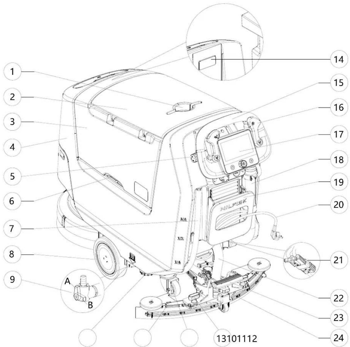
MACHINE DESCRIPTION MACHINE STRUCTURE
- Can holder
- Recovery tank cover
- Recovery tank
- Solution tank
- Handlebar lock knob (T)
- Tank lifting handle
- Solution drain and level check hose
- Front driving wheels
- Solution valve:
A) Open valve (T)
B) Closed valve (T)
- Solution filter (T)
- Squeegee
- Rear pivoting wheels
-
Squeegee mounting handwheels (T)
-
Serial number plate/technical data/conformity certification
- Drive handlebar
- Forward/reverse gear and activation paddle
- Control panel
- Recovery water drain hose (T)
- Battery charger cable housing and document holder
- Battery charger cable
- Battery connector (red).
- Squeegee vacuum hose
- Squeegee lifting/lowering pedal
- Squeegee adjusting knob
(T) Touch point with blue color

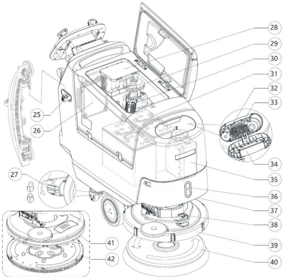
MACHINE STRUCTURE (Continues)
- Squeegee hook (T)
- Battery charger
- Electromagnetic brake locking/unlocking lever
- Debris collection tank (T)
- Vacuum system motor
- Vacuum grid with automatic shut-off float
- Batteries
- Water removable filler hose (T)
- Solution tank front filler
- Solution tank front filler cap (T)
- EcoFlex detergent canister
- Front light/Front light with laser (*)
- Front panel
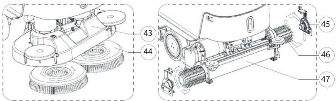
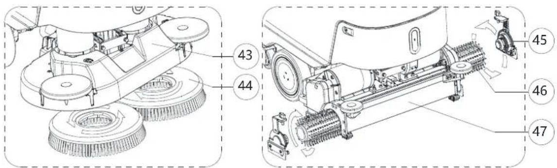
-
Straight forward movement adjusting knob
-
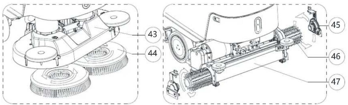
Disc brush deck
- Single disc brush
- REV deck
- REV brush
- Dual disc brush deck
- Dual disc brush
- Cylindrical brush side hook
- Cylindrical brush
- Cylindrical brush deck
(*) Optional for BASIC version

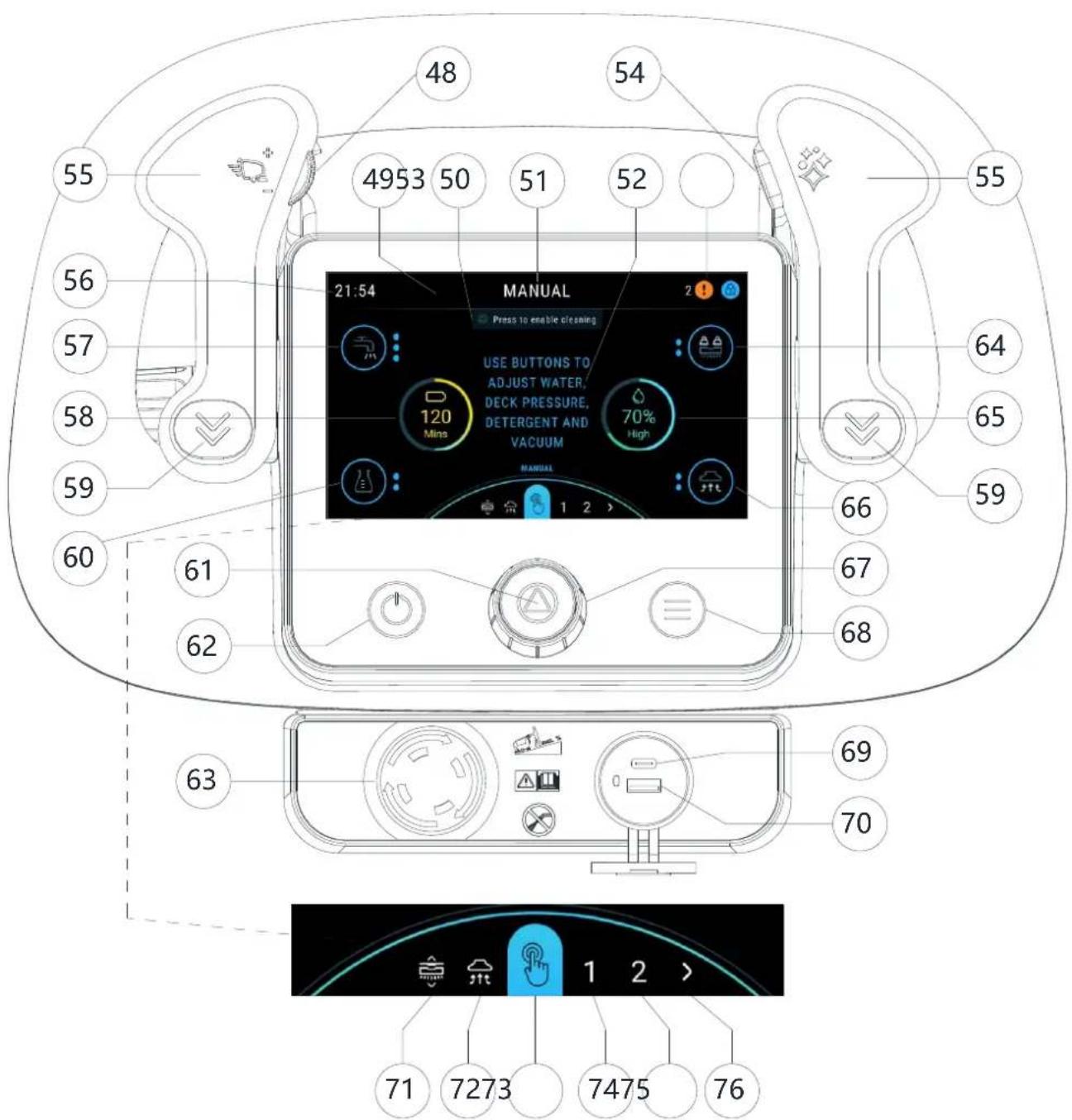
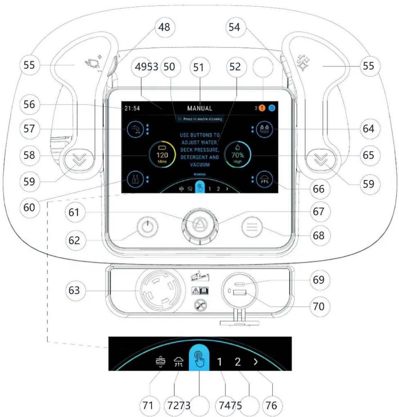
CONTROL PANEL
- Speed control dial (T)
- Header
- Prompts area
- Preset name
- Information area
- Status area
- Burst of power button (T)
- Forward paddle
- Clock
- Water level button (Only in manual mode)
- Battery level graphic
- Reverse paddle
- Detergent level button (Only in manual mode)
- Start / stop / select button
- Power button
-
Emergency stop button
-
Deck pressure button (Only in manual mode)
- Water level graphic
- Vacuum button (Only in manual mode and vacuum mode)
- Smart dial (T)
- Menu button
- Type-C
- USB-A
- Brush click on / off mode (Brush disc machine only)
- Vacuum only mode
- Manual mode
- Presets mode 1
- Presets mode 2
- More presets
(T) Touch point with blue color
USE/OPERATION

WARNING!
On some points of the machine there are some adhesive plates indicating:
ANGER
'ARNING
AUTION
CONSULTATION
While reading this Manual, the operator must pay particular attention to the symbols shown on the plates (see Visible Symbols on The Machine paragraph).
Do not cover these plates for any reason and immediately replace them if damaged
NEW USER CREATION AND LOGIN INTERFACE
-
When the machine is first activated, the machine will guide the creation of a "SUPERVISOR USER" account. This is the highest authority of the machine, and the operator must complete the creation of this account to proceed to the next step. "SUPERVISOR USER" can create more users in the settings/ user access interface. (see the MENU INTERFACE paragraph in Maintenance chapter)
-
"TRAINEE USER" password (0000) For first time use / new operator. Main difference is starts in training mode with all pop ups enabled.
- "BASIC USER" password (Creating by "SUPERVISOR USER") For general user, only presets enabled by supervisor are available. (No manual mode available).
- "ADVANCED USER" password (Creating by "SUPERVISOR USER") Manual mode available. Ability to change detergent ratios / settings.
-
"SUPERVISOR USER" password (Create when the machine is first activated or creating by exist "SUPERVISOR USER) All settings and presets setups available, ability to add new users, change deck configuration, change batteries etc.
-
After restarting the machine, the machine will enter the password login interface shown in Figure 1, then enter your password to start the machine.
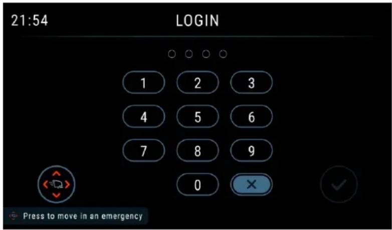
Figure 1
BATTERY CHECK/SETTING ON A NEW MACHINE

WARNING!
The electric components of the machine can be seriously damaged if the batteries are either improperly installed or connected.
The batteries must be installed by qualified personnel only.
Check the batteries for damage before installation.
Handle the batteries with great care.
LI-ION BATTERY VERSION: The machine requires at least a 24 V battery, connected according to the diagram shown in Figure 2.
LEAD BATTERY VERSION: The machine requires 2 12 V batteries, connected according to the diagram shown in Figure 3.
Batteries already installed on the machine
- Ensure that the battery connector (21) is connected.
When first using the machine with new batteries, perform a full charging cycle (see the procedure in Maintenance chapter).
BATTERY INSTALLATION

DANGER!
This machine requires sealed exclusive use Li-ion battery.
Li-ion Battery Installation
- Turn off the machine with start/stop button (62).
- Disconnect the battery connector (21).
- Lift the cover (2) and check that the recovery tank (3) is empty; if not, empty it using the drain hose (18).
- Close the cover (2).
- Grasp the handle (6) and carefully lift the tank (3).
- Loosen the screws to take down the box cover (if have).
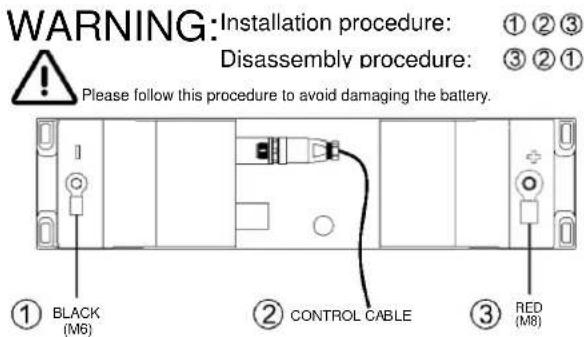
- Operator must disconnect the positive terminal first, second the control cable and then disconnect negative terminal on the battery and lift the battery up a little then can pull it out in the left or right side.
- Replace the new battery to the machine and reconnect the terminals and control cable to the battery.

DANGER!
For 24V 64Ah Li-ion battery, pay special attention when connecting the battery pins. The black cable must be connected to the negative pin (-) of the battery first, then the control cable and then the red cable must be connected to the positive pin (+). A wrong connection or sequence can damage the battery.
- Close the box cover and re-lock the screws which are loosened before and then close the cover.
Battery Charging
- Fully charge the batteries (see the procedure in Maintenance chapter).
LI-ION BATTERY
One 24 V 64Ah Li-ion battery
LI-ION BATTERY
One 24 V 50Ah Li-ion battery
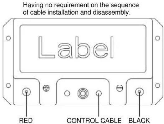
Figure 2
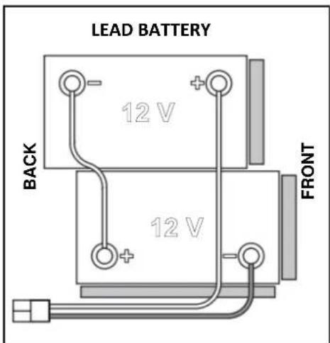
Figure 3
BEFORE MACHINE START-UP

WARNING!
When starting the machine, make sure that there is no foreign material between the deck and the tank assembly which could obstruct the deck movement. If the machine has been turned off without lifting the deck, the deck would lift automatically at next machine start-up.
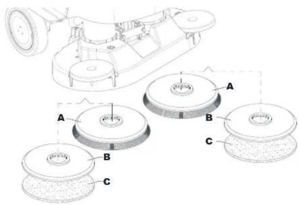
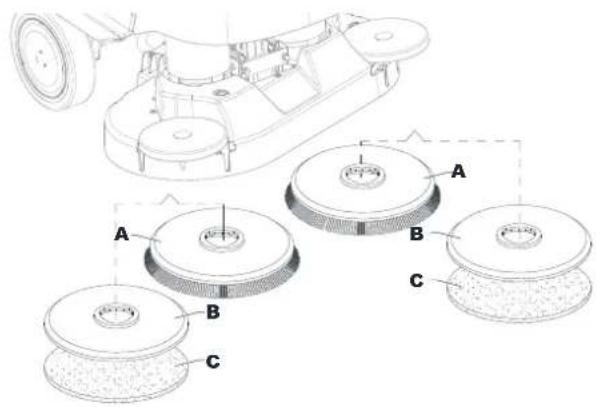
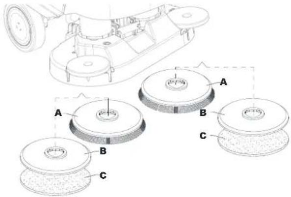
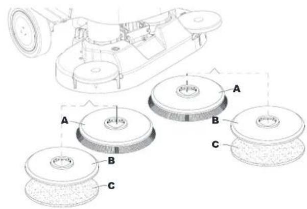
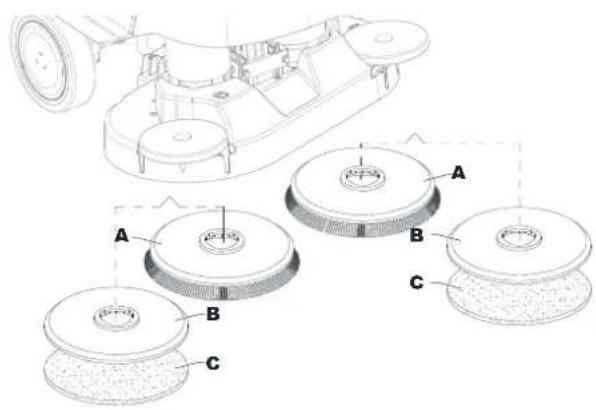
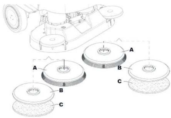
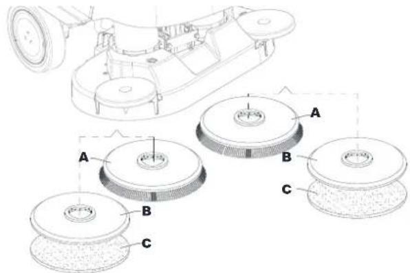
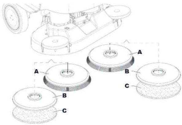
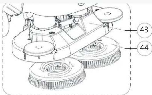
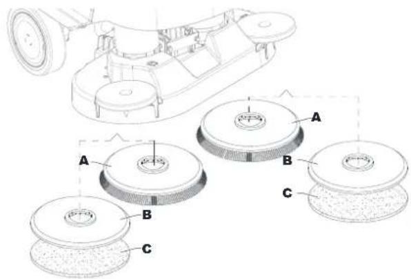
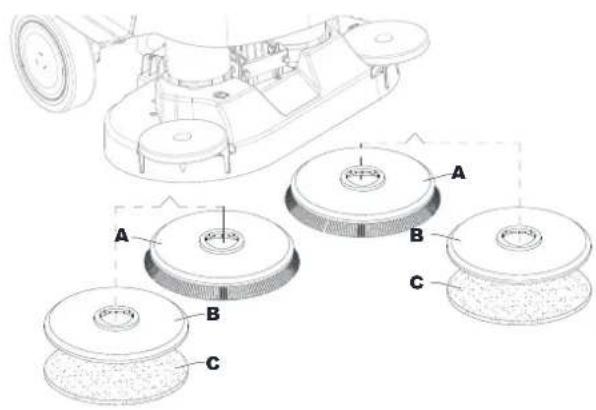
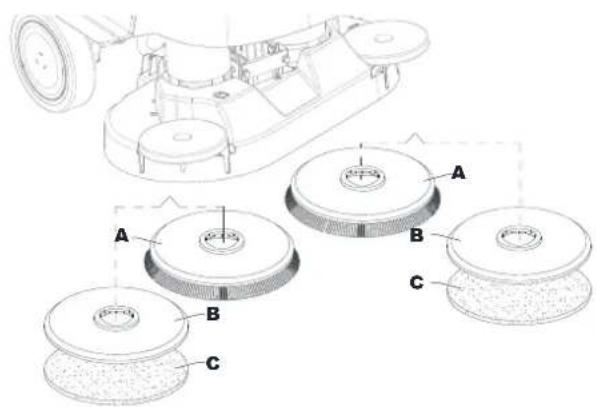
Brush or pad-holder removal/installation (Brush disc system)
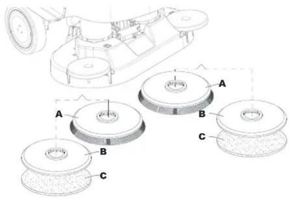
According to the kind of cleaning to be performed, the machine can be equipped either with the brush (A, Fig. 4) or the pad-holder (B) with pad (C) together with the appropriate deck.
- Place the brush (A) or the pad-holder (B) under the brush deck (39) / Dual disc deck (43).
- Press start/stop button (62) and enter password to start machine. Roto dial button (67) to select brush click on/off mode (71), press dial button (61) to confirm.
- 3.Press the Attach brush(es) button on the screen to lower the deck onto the brush.
- 4.Brush motors rotate automatically until the brush is engaged.


CAUTION!
Make sure the brush is placed directly below and repeat the procedure if it does not install smoothly. Swaying the machine slightly from side to side according to the brush position can improve the success rate of automatic installation.
- To remove the brush, the deck must be lifted and roto dial button (67) to select brush click on/off mode. Press dial

button (61) to confirm. Press the Release brush(es) button. The brush will run for a few seconds and stop, wait until the brush is lowered onto the floor.
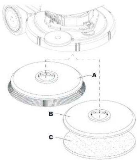

Figure 4
Available brushes and their relevant application guides (suggestions only)
| Models | 46 GRIT | 80 GRIT | 180 GRIT | 240 GRIT | 500 GRIT | PROLENE | PROLITE | UNION MIX |
| General cleaning: | ||||||||
| Concrete | ||||||||
| Terrazzo floor | ||||||||
| Ceramic tiles/quarrystones | ||||||||
| Marble | ||||||||
| Vinyl tiles | ||||||||
| Rubber tiles | ||||||||
| Polishing: | ||||||||
| Rubber tiles | ||||||||
| Marble | ||||||||
| Vinyl tiles | ||||||||
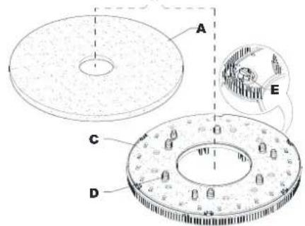
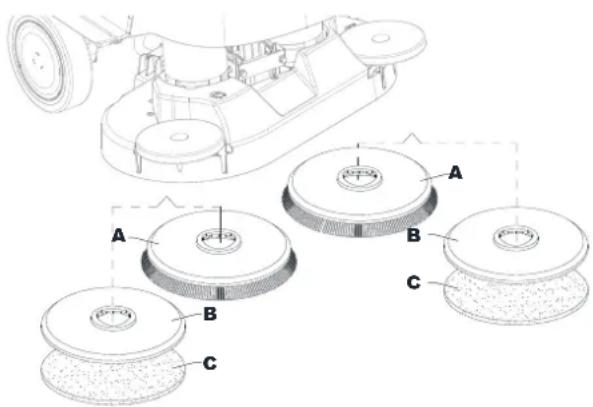
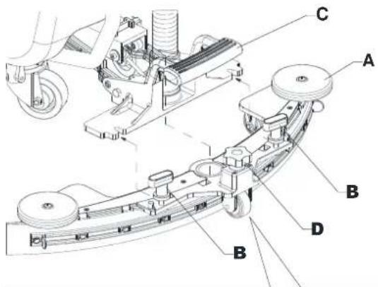
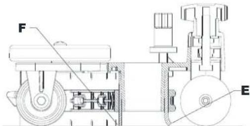
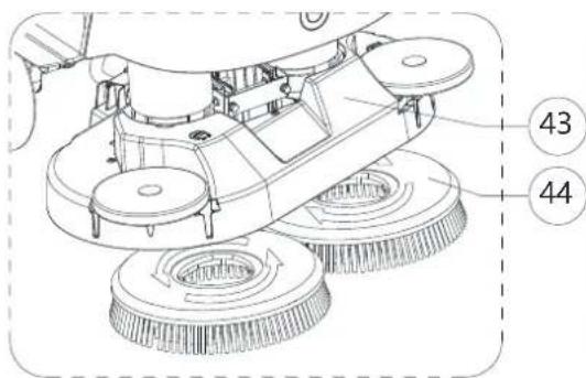
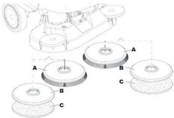
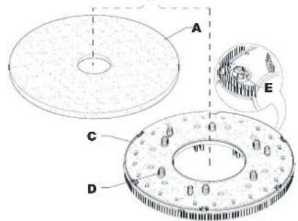
Pad-holder removal/installation (REV system)
- Make sure that the REV deck (41) is lifted.
- Turn off the machine with the start/stop button (62).
- According to the kind of cleaning to be performed, install the pad (A, Fig. 5) or the brush (C, optional) and note the following:
- Place the pad (A) under the deck and press it until it is fastened with the Velcro of the drive disc (B).
- Place the brush (C, optional) under the deck, and then match the centering pins (D) to the respective holes of the drive disc (B), and then engage the brush with the three mounting screws (E).
- To remove the pad or brush, proceed in the reverse order.
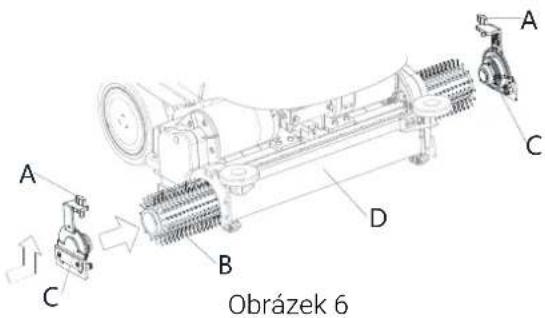
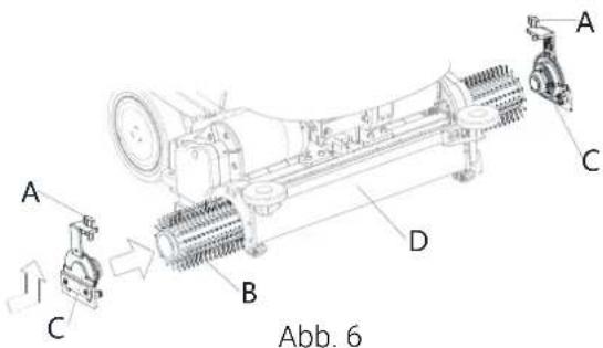
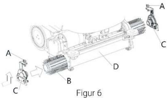
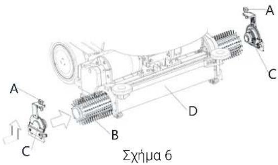
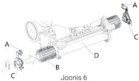
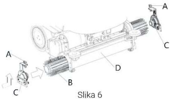
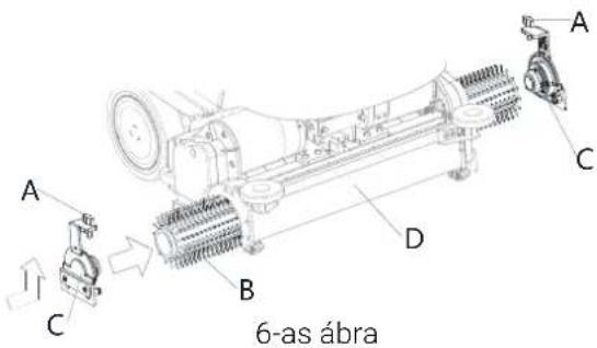
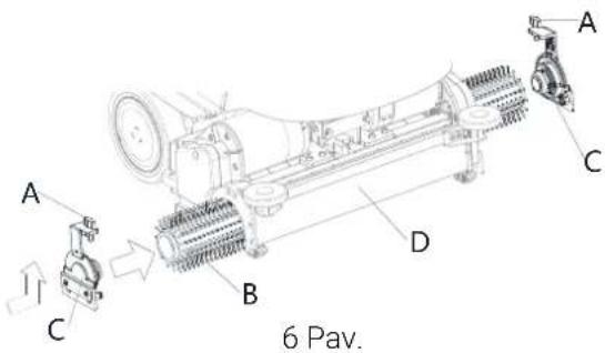
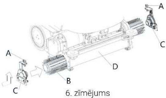
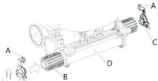
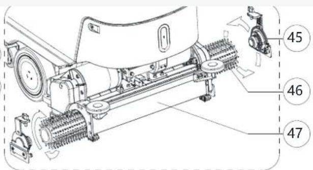
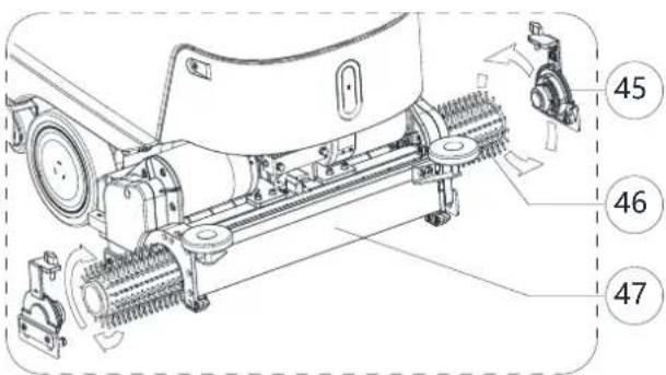
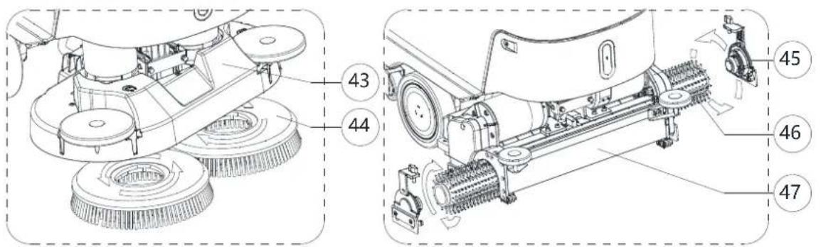
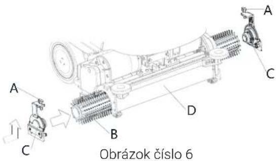
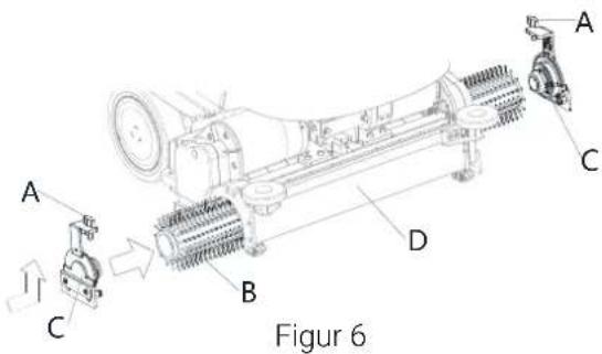
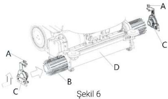
Brush removal/installation (Cylindrical system)
- Make sure that the cylindrical deck (47) is lifted.
- Turn off the machine with the start/stop button (62)
- According to the kind of cleaning to be performed, install the brush (B, Fig. 6) and note the following:
- Release the screw (A) and remove the side hook (C) from brush deck (D).
- Install the brush (B) in the deck (D). Install the side hook (C) for brush and lock the screw(A).
- To remove the brush, proceed in the reverse order.
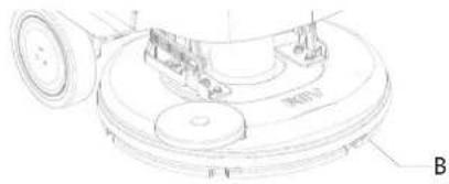
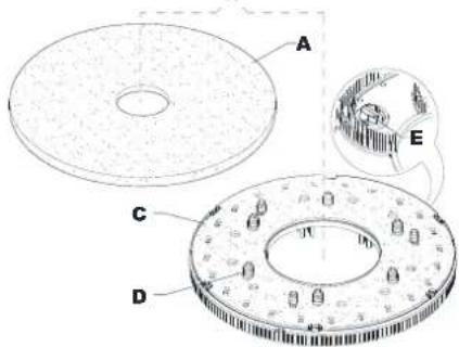
Figure 5
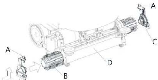
Figure 6
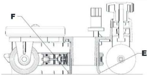
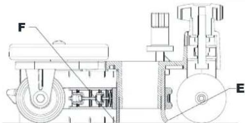
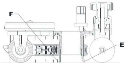
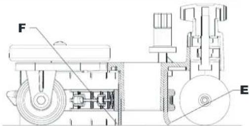
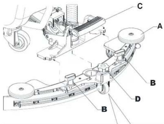
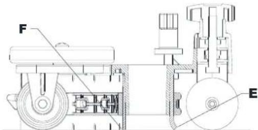
Squeegee installation
- Install the squeegee (A, Fig. 7) and fasten it to the bracket (C) with the handwheels (B).
- If necessary, adjust the squeegee with the knob (D) so that the rear blade (E) and front blade (F) touch the floor as shown in the figure.
Solution tank filling

CAUTION!
Use only low-foam and non-flammable detergents, intended for automatic scrubber applications.

WARNING!
When using floor cleaning detergents, follow the instructions on the labels of the detergent bottles. To handle floor cleaning detergents, wear suitable gloves and protections.

NOTE
If the machine is equipped with EcoFlex system pour clean water in the tank, otherwise pour solution.
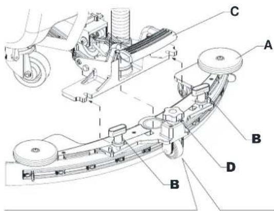

Figure 7
- Ensure that the solution valve (9) is open (9-A).
- To fill the solution tank (4) use the front filler (33).

(For machines without EcoFlex system)
- Fill the tank (4) with a solution suitable for the work to be performed. Do not fill the tank completely, leave a few inches or CM from the edge. Use the level hose (7) as reference. Always follow the dilution instructions on the label of the chemical product used to prepare the solution. The solution temperature must not exceed 40 °C .
(For machines with EcoFlex system)
- Fill the tank (4) with clean water. Use the water removable filler hose (32). Do not fill the tank completely, leave a few inches from the edge. Use the level hose (7) as reference. The water temperature must not exceed 40 °C .
Detergent tank filling (For machines with EcoFlex system)
- Lift the cover (2) and check that the recovery tank (3) is empty; if not, empty it using the drain hose (18).
- Close the cover (2).
- Grasp the handle (6) and carefully lift the tank (3).
- Fill the tank (34) with a detergent suitable for the work to be performed (highly concentrated detergent). Do not fill the detergent tank completely, leave a few inches from the edge.

NOTE
To accelerate filling of the hoses and system operation (with a new system, if the system has been emptied for cleaning, etc.), it is a good idea to run the Detergent PURGE program first. (see the procedure in the Maintenance chapter)
Operating handle Angle adjustment
- Ensure that the machine is off.
- Unscrew the handle lock knob (5) until the handlebar (B, Fig. 8) can be moved.
- Adjust to the operating Angle and lock through handle lock knob (A).
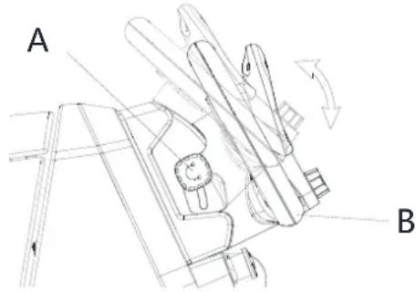
Figure 8
MACHINE START AND STOP
Starting the machine
- Prepare the machine as shown in the previous paragraph.
- Press start/stop button (62). In the first 2 seconds after machine start-up, the screen displays the password interface. Enter password to Start machine.
- The screen display the main interface.

NOTE
Check the battery charge level.
When the screen display battery symbol (58) is low, the batteries have to be charged (see the procedure in Maintenance chapter).
- Drive the machine to the area it is required by starting it with your hands on the handlebar (15) and pushing the paddle (16) forward to move forward, and backwards to move in reverse. The speed can be adjusted by pressing the paddle (16) more or less. The maximum speed can be set with the speed adjustment knob (48).
Stopping the machine
- Stop the machine by releasing the paddle (16).
- Turn off the machine by pressing the start/stop button (62).

NOTE
If the machine is on but not working, it automatically turns off after 5 minutes.
- Make sure that the machine cannot move independently.

WARNING!
In the event of an emergency, to stop all machine functions immediately, press the emergency stop button (63).
MACHINE OPERATION (SCRUBBING/DRYING)
- Start the machine as shown in the previous paragraph.
- Lower the squeegee (11) with the pedal (23).
-
Press the start/stop button (62) and enter password to start the machine. Roto dial button (67) to select clean mode as follows and press dial button (61) to confirm.
-
Manual mode (73)-Solution flow, detergent flow, brush pressure, vacuum level can be adjusted by screen.
- Smart clean mode (74) - Presetting, cannot be adjusted by screen.
- Standard clean mode (75) -Presetting, cannot be adjusted by screen.
-
Deep clean mode/ Floor prep mode (REV only) -Presetting, cannot be adjusted by screen.
-
lower the brush deck and start scrubbing and drying. Start cleaning by maneuvering the machine and pressing the paddle (16) when the brush is lowered to the ground. If necessary, adjust the maximum speed with the speed adjustment knob (48).
-
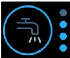
Adjust the solution flow by pressing the solution flow adjustment button (manual mode only) as necessary, depending on the type of cleaning to be performed.

NOTE
For the first 3 flow levels (Fig. 9), the amount of solution dispensed is automatically adjusted according to the machine speed, in order to obtain a constant amount of solution per linear meter of cleaning.
natural_image
Blue circular icon with a faucet symbol and three dot pattern below (no text or numbers)| Version | Solution flow values (cl/meter) | Solution full flow mode (liter/minute) it requires a supervisor user to enable it. | |||
| Lev.0 | Lev.1 | Lev.2 | Lev.3 | Lev.4 | |
| Disc | OFF | 0,75 | 1,5 | 3,0 | 3,7 liter/minute |
| REV | OFF | 0,38 | 0,75 | 1,5 | |
| Dual disc | OFF | 0,90 | 1,8 | 3,6 | |
| Cylindrical | OFF | 1,0 | 1,83 | 2,8 | |
Figure 9
- If necessary, to reduce the noise, turn on the vacuum system mute function by pressing the Vacuum system adjustment/deactivation button (66) (manual mode only).

NOTE
For correct scrubbing/drying of floors at the sides of the walls, Nilfisk suggests to go near the walls with the right side of the machine as shown in figure 10.
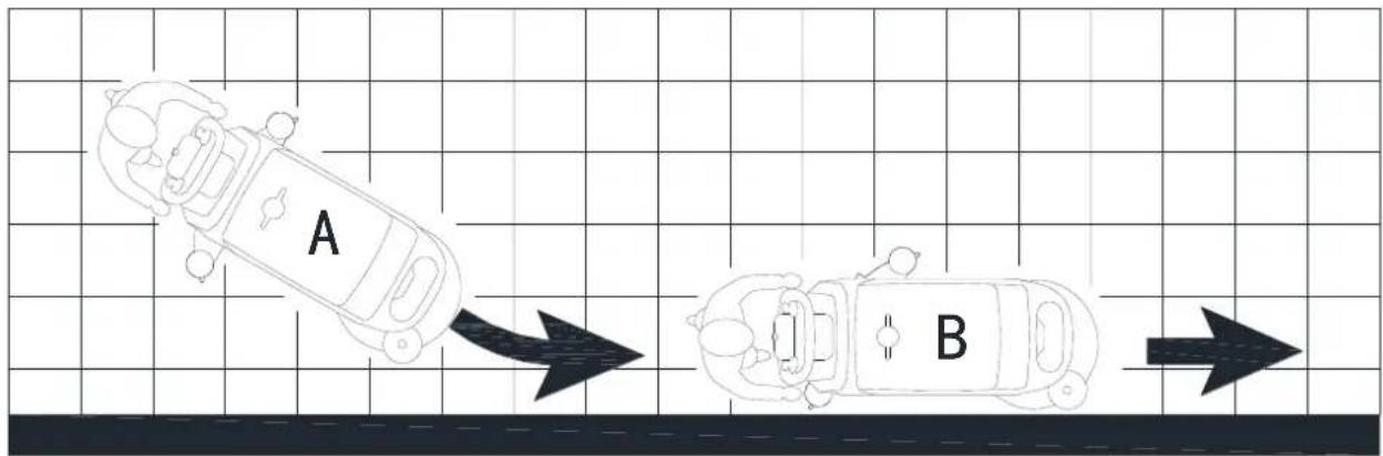
flowchart
graph TD
    A["A"] --> B["B"]
    style A fill:#f9f,stroke:#333
    style B fill:#bbf,stroke:#333
Figure 10

WARNING!
To avoid any damage to the floor surface, turn off the brush when the machine is stationary, especially when the extra pressure function is on.
- At the end of the work, press the dial button (61) to lift the brush deck. After 10 seconds, the vacuum system turns off too.
- Lift the squeegee (11) with the pedal (23).

Adjusting of detergent concentration in the cleaning solution (Manual mode only)
• (For machines with EcoFlex system)
- The system for mixing the detergent in the cleaning solution is automatically activated when the brush is running.
- The percentage of detergent added to the cleaning solution is set to level 1 (Fig. 11).
- By pressing the detergent percentage adjustment push-button (60), it is possible to set the percentage level to 2, or reset it to level 0.
- The set percentages are shown on the display (60).

natural_image
Simple line icon of a laboratory flask inside a circle, with two dots beside it (no text or symbols)| Percentage of detergent | ||
| Lev.0 | Lev.1 | Lev.2 |
| OFF | 0.40%1:250 | 0.80%1:125 |
Figure 11
Burst of power button
Press the burst of power button (54) when stronger washing power is needed temporarily.
With the burst of power activated, increased solution flow, activation of the extra pressure of the brush and an increase in the solution detergent concentration (level 2 if the level was set to 1 - level 1 if the level was set to 0) is obtained. The screen displays burst of power countdown of 60s. Press the burst of power button (54) again, to restore the original settings.

NOTE
If the burst of power button (54) is not pressed again, the original settings are restored automatically after 60 seconds.

NOTE
All of the above solution flow and detergent concentration values are factory settings. To change these settings, see the Supervisor paragraph in Maintenance chapter.
REV system (for REV version only)
Press the Floor prep mode when a specific washing mode is required.
With the REV system activated the drive speed is decreased, the brush extra pressure is activated, the detergent is stopped and the cleaning solution quantity is reduced.
Working with brush extra pressure function turned on (Manual mode only)
If the floor proves to be particularly difficult to clean, it is possible to turn on the brush extra pressure function, according to the following procedure:
- Press start/stop button (62) and enter password to start machine. Roto dial button (67) to select manual mode, press dial button (61) to confirm. Lower the brush deck as shown in "Starting The Machine" paragraph.
- Press the extra pressure button (64). The extra pressure function activation is shown icon on the display (64).
- To return to normal pressure, press the extra pressure button (64) again to switch.

CAUTION!
In case of brush motor overload, due to foreign bodies which prevent them from turning, or to excessively aggressive floors/brushes, the safety system stops the brush after about one minute of continuous overload. If the overload takes place when the extra pressure function is on, the system automatically turns the extra pressure function off. If the overload persists, the brush stops. To start scrubbing again after a brush stop due to overload, turn off and then on the machine with start/stop button (62).
Battery discharge during operation
When the battery (58) displays low in the screen, it is advisable to charge the batteries, because the residual autonomy will last for a few minutes (depending on battery characteristics and work to be performed). After a few seconds, the brush is automatically tuned off, while the vacuum system and the drive system stay on, to finish drying the floor and drive the machine to the appointed recharging area.

CAUTION!
Do not use the machine with discharged batteries, to avoid damaging the batteries and reducing the battery life.
TANK EMPTYING
An automatic shut-off float system (30) turns off the vacuum system when the recovery tank (3) is full.
The vacuum system deactivation is signaled by a sudden increase in the vacuum system motor noise, and the floor is not dried.

CAUTION!
If the vacuum system turns off accidentally (for example, when the float is activated because of a sudden machine movement), to resume the operation: turn off the vacuum system, then open the cover (2) and check that the float inside the grid (30) has gone down. Then close the cover (2) and turn on the vacuum system again.
When the recovery tank (3) is full, empty it according to the following procedure.
Recovery tank emptying
- Raise the brush deck.
- Lift the squeegee (11) with the pedal (23).
- Drive the machine to the appointed disposal area.
- Turn off the machine with the start/stop button (62).
- Empty the recovery tank (3) with the drain hose (18). Then, rinse the tank with clean water.
Solution tank emptying
- Perform steps 1 to 4.
- Empty the detergent solution tank (4) using the level hose (7). Then, rinse the tank with clean water.
AFTER USING THE MACHINE
After working, before leaving the machine:
- Remove the brush as shown in the relevant paragraph.
- Turn off the machine with the start/stop button (62).
- Empty the tanks (3) and (4) as shown in the relevant paragraphs.
- Perform the daily maintenance procedures (see the Maintenance chapter).
- Store the machine in a clean and dry place, with the brush and the squeegee lifted or removed.
MACHINE LONG INACTIVITY
If the machine is not going to be used for more than 30 days, proceed as follows:
- Perform the procedures shown in After using the machine paragraph.
- For versions with EcoFlex system, empty the detergent tank (35) and clean the system with a draining cycle (see the procedure in Maintenance chapter).
- Close the solution tank valve (9-B).
- Disconnect the battery connector (21).

MAINTENANCE
The lifespan of the machine and its maximum operating safety are ensured by correct and regular maintenance.
The following table provides the scheduled maintenance. The intervals shown may vary according to particular working conditions, which are to be defined by the person in charge of the maintenance.

WARNING!
The procedures must be performed with the machine off and the battery disconnected.
Moreover, read carefully the instructions in the Safety chapter before performing any maintenance procedure.
All scheduled or extraordinary maintenance procedures must be performed by qualified personnel, or by an authorised Service Center.

CAUTION!
When the Service icon appears on the display (52), contact an authorised Nilfisk Service Centre for scheduled maintenance.
This Manual describes only the simplest and most common maintenance procedures. For other maintenance procedures shown in the Scheduled Maintenance Table, refer to the Service Manual that can be consulted at any Service Center.
SCHEDULED MAINTENANCE TABLE
| Procedure | Daily, after using the machine | Weekly | Every six months | Yearly |
| Battery Charging | ||||
| Squeegee Cleaning | ||||
| Brush/pad cleaning | ||||
| Recovery tank, debris tray, and vacuum grid with float cleaning, and cover gasket, and CYL debris hopper check | ||||
| Detergent System cleaning and washing (optional) | ||||
| Squeegee blade check | ||||
| Solution Filter Cleaning | ||||
| Squeegee blade replacement | ||||
| Drive and brush motor vent check and cleaning | (1) | |||
| Brush motor carbon brush check or replacement | (1) | |||
| Drive system motor carbon brush check or replacement | (1) | |||
| Brush deck vibration-damper replacement (only for REV version) | (1) |
(1) This maintenance procedure must be performed by an authorised Nilfisk Service Center.
Machine material composition and recyclability
| Type | Recyclable percentage | Weight % | |||
| Single disc deck | REV deck | Dual disc deck | CYL deck | ||
| Aluminum | 100% | 8 % | 8 % | 8 % | 8 % |
| Electric motors - various | 29 % | 30 % | 35 % | 33 % | 29 % |
| Ferrous materials | 100% | 4 % | 4 % | 4 % | 5 % |
| Wiring harness | 80 % | 3% | 2% | 3% | 3% |
| Liquids | 100% | 0 % | 0 % | 0 % | 0 % |
| Plastic - non-recyclable material | 0 % | 3% | 2% | 3% | 3% |
| Plastic - recyclable material | 100% | 12 % | 11 % | 11 % | 12 % |
| Polyethylene | 92 % | 37 % | 35 % | 35 % | 37 % |
| Rubber | 20 % | 2 % | 2 % | 2 % | 2 % |
ВЪВЕДЕНИЕ

ПРЕДУПРЕЖДЕНИЕ!
ПУЛТ ЗА УПРАВЛЕНИЕ
Фигура 1
Фигура 5
natural_image
Blue circular icon with a faucet symbol and three dot pattern on the right (no text or numbers)natural_image
Blue circular icon with a beaker and three dots, next to two smaller dots (no text or symbols)ÚČEL A OBSAH PŘÍRUČKY


OVLÁDACÍ PANEL
Obrázek 1
KONTROLA/NASTAVENÍ BATERIÍ NA NOVÉM STROJI

VAROVÁNÍ!
Obrázek 5
Obrázek 7
(Pro stroje bez systému EcoFlex)
PROVOZ STROJE (DRHNUTÍ/SUŠENÍ)
natural_image
Blue circular icon with a faucet symbol and three dot columns on the right (no text or numbers)natural_image
Simple line icon of a laboratory flask inside a circle, with two dots beside it (no text or symbols)| Procento saponátu | ||
| Lev.0 | Lev.1 | Lev.2 |
| VYP | 0,40 % 1:250 | 0,80 % 1:125 |
Obrázek 11
DLOUHÁ NEČINNOST STROJE
BEDIENFELD
Abb. 1
natural_image
Technical line drawing of a mechanical component with labeled parts (no readable text or symbols)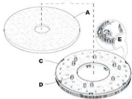
Abb. 5
Saugleistenmontage
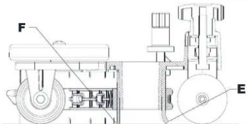
Abb. 7
natural_image
Blue circular icon with a faucet symbol and three vertical dot arrays on black background (no text or symbols)natural_image
Blue circular icon with a beaker symbol and two dots, no text or labels present.FORMÅLET MED VEJLEDNINGEN OG DENS INDHOLD
SYMBOLER ANVENDT I DENNE MANUAL

FARE!
MASKINSTRUKTUR (Fortsat)

KONTROLPANEL
Figur 1
KONTROL/INDSTILLING AF BATTERI PÅ NY MASKINE

ADVARSEL!
Maskinens elektriske komponenter kan beskadiges alvorligt, dersom batterierne enten installeres eller forbindes forkert.
F∅R OPSTART AF MASKINEN

ADVARSEL!
Figur 5
Figur 7
natural_image
Blue circular icon with a faucet symbol and three droplets on the right side (no text or numbers)| Version | Rengøringsmiddelværdier (cl/meter) | Rengøringsmidlets fuldstrømstilstand (liter/minut) kræver en supervisorbruger for at aktivere den. | |||
| Lev.0 | Lev.1 | Lev.2 | Lev.3 | Lev.4 | |
| Skive | FRA | 0,75 | 1,5 | 3,0 | 3,7 liter/minut |
| REV | FRA | 0,38 | 0,75 | 1,5 | |
| Dobbelt skive | FRA | 0,90 | 1,8 | 3,6 | |
| Cylindrisk | FRA | 1,0 | 1,83 | 2,8 | |
Figur 9
natural_image
Simple line icon of a laboratory flask inside a circle, with two dots beside it (no text or symbols)| Procentdel af rengøringsmiddel | ||
| Lev.0 | Lev.1 | Lev.2 |
| FRA | 0,40%1:250 | 0,80%1:125 |
Figur 11
Strømudbrud-knap
ΠΙΝΑΚΑΣ ΕΛΕΓΧΟΥ
Σχήμα 1
natural_image
Technical line drawing of a mechanical component with labeled parts (no readable text or symbols)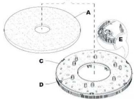
Σχήμα 5
Σχήμα 7
natural_image
Blue circular icon with a faucet symbol and three dots on the right side (no text or numbers)natural_image
Blue circular icon with a beaker symbol and two dots, no text or labels present.PROPÓSITO Y CONTENIDOS DE ESTA GUÍA
ESTRUCTURA DE LA MÁQUINA (Sigue)

PANEL DE CONTROL
Figura 1

Figura 5
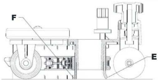
Figura 7
natural_image
Blue circular icon with a faucet symbol and three dot columns on the right (no text or numbers)natural_image
Blue circular icon with a beaker and three dots, next to two smaller dots (no text or symbols)JUHENDI EESMÄRK JA SISU
MASINA KONSTRUKTSIOON (Järgneb)

JUHTPANEEL
Joonis 1
AKU KONTROLLIMINE/SEADISTAMINE UUEL MASINAL
HOIATUS!

natural_image
Technical line drawing of a mechanical component with labeled parts (no readable text or symbols)
Joonis 5
Kaabitsa paigaldamine
Joonis 7
natural_image
Blue circular icon with a faucet symbol and three vertical dot columns on black background (no text or symbols)natural_image
Simple line icon of a laboratory flask inside a circle, with two dots beside it (no text or symbols)| Pesuaine protsent | ||
| Lev.0 | Lev.1 | Lev.2 |
| VÄLJAS | 0,40%1:250 | 0,80%1:125 |
Joonis 11
OPPAAN SISÄLTÖ JA TARKOITUS
KONEESSA NÄKYVÄT SYMBOLIT
VAROITUS!

OHJAUSPANEELI
Kuva 1
AKUN TARKISTUS / ASETUS UUDESSA KONEESSA
VAROITUS!


Kuva 5
natural_image
Blue circular icon with a faucet symbol and three dot columns on the right (no text or numbers)natural_image
Blue circular icon with a beaker and three dots, next to two smaller dots (no text or symbols)| Pesuaineen prosenttiosuus | ||
| Lev.0 | Lev.1 | Lev.2 |
| POIS | 0,40 % 1:250 | 0,80 % 1:125 |
Kuva 11
Voimasysäyspainike
BUT ET CONTENU DU GUIDE
DÉCLARATION DE CONFORMITÉ
STRUCTURE DE LA MACHINE (suite)
PANNEAU DE COMMANDE
Figure 1
VÉRIFICATION/RÉGLAGE DE LA BATTERIE SUR UNE NOUVELLE MACHINE
AVERTISSEMENT !


Figure 5
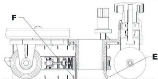
Figure 7

REMARQUE
natural_image
Blue circular icon with a faucet symbol and three dot pattern on the right (no text or numbers)natural_image
Simple icon of a laboratory flask with blue outline and two dots, no text or symbols presentSVRHA I SADRŽAJ VODIČA
STRUKTURA STROJA (nastavak)
- Kuka za brisač (T)
- Punjač baterija
- Poluga za blokiranje/deblokiranje elektromagnetske kočnice
- Spremnik za skupljanje otpadaka (T)
- Motor usisnog sustava
- Usisna rešetka s plovkom sa zatvaračem za automatsko zatvaranje
- Baterije
- Cijev za sipanje vode koja se može skinuti (T)
- Prednji spremnik otopine
- Čep prednjeg spremnika otopine (T)
- Kanistar za deterdžent EcoFlex
- Prednje svjetlo / prednje svjetlo s laserom (*)
- Prednja ploča
-
Gumb za podešavanje pravocrtnog kretanja unaprijed
-
Okrugla noseća ploča četke
- Četka s jednim diskom
- REV noseća ploča
- REV četka
- Dvostruka okrugla noseća ploča četke
- Četka s dvostrukim diskom
- Bočna kuka s valjkastom četkom
- Valjkasta četka
- Noseća ploča valjkaste četke

UPRAVLJAČKA PLOČA
Slika 1
PROVJERA/PODEŠAVANJE BATERIJA NA NOVOM STROJU

UPOZORENJE!
Može doći do ozbiljnih oštećenja električnih komponenti stroja ako su baterije nepravilno instalirane ili spojene.
Slika 4
Slika 5

Slika 7
- Provjerite je li ventil otopine za pranje poda (9) otvoren (9-A).
- Da biste napunili spremnik otopine za pranje poda (4), koristite prednji otvor za punjenje (33).
natural_image
Icon of a faucet with three water droplets, next to a vertical grid of blue dots (no text or symbols)| Verzija | Vrijednosti protoka otopine (cl/metar) | Način punog protoka otopine (l/min) omogućuje korisnik nadzornik. | |||
| Lev.0 | Lev.1 | Lev.2 | Lev.3 | Lev.4 | |
| Disk | ISKLJ. | 0,75 | 1,5 | 3,0 | 3,7 l/min |
| REV | ISKLJ. | 0,38 | 0,75 | 1,5 | |
| Dvostruki disk | ISKLJ. | 0,90 | 1,8 | 3,6 | |
| Valjkasti | ISKLJ. | 1,0 | 1,83 | 2,8 | |
Slika 9
- Ako je potrebno, da biste smanjili buku, aktivirajte funkciju tihog rada usisnog sustava pritiskom na gumb za namještanje/deaktivaciju usisnog sustava (66) (samo ručni način rada).

NAPOMENA
natural_image
Blue circular icon with a beaker symbol inside, next to two dark dots (no text or symbols)| Postotak deterdženta | ||
| Lev.0 | Lev.1 | Lev.2 |
| ISKLJ. | 0,40 % 1:250 | 0,80 % 1:125 |
Slika 11
Gumb za pojačavanje snage
Pritisnite gumb za pojačavanje snage (54) kad je privremeno potrebna veća snaga pranja.
AZ ÚTMUTATÓ CÉLJA ÉS TARTALMA

VEZÉRLÓPULT
1-as ábra
AKKUMULÁTOR ELLENŐRZÉS / AZ ÚJ BERENDEZÉS BEÁLLÍTÁSA
FIGYELMEZTETÉS!

4-as ábra
natural_image
Technical line drawing of a mechanical component with labeled parts (no readable text or symbols)
5-as ábra

7-as ábra
natural_image
Blue circular icon with a faucet symbol and vertical dot pattern on the right (no text or numbers)natural_image
Simple line icon of a beaker with three tubes inside, next to two dots (no text or symbols)SCOPO E CONTENUTI DELLA GUIDA
STRUTTURA DELLA MACCHINA (continua)


PANNELLO DI CONTROLLO
Figura 1
natural_image
Technical line drawing of a mechanical component with labeled parts (no readable text or symbols)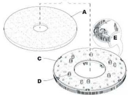
Figura 5
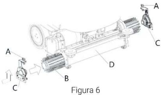

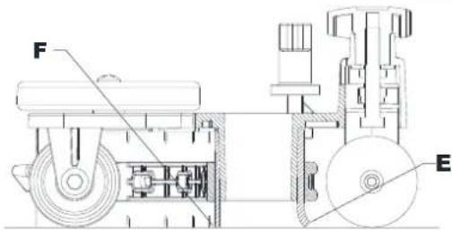
Figura 7
natural_image
Blue circular icon with a faucet symbol and three dot columns on the right (no text or numbers)natural_image
Simple line icon of a beaker with liquid inside a circle, next to two dots (no text or symbols)| Percentuale di detergente | ||
| Lev.0 | Lev.1 | Lev.2 |
| OFF | 0,40%1:250 | 0,80%1:125 |
Figura 11
INSTRUKCIJOS PASKIRTIS IR TURINYS
MAŠINOS STRUKTŪRA (Tęsinys)
VALDYMO SKYDELIS
1 Pav.
AKUMULIATORIAUS TIKRINIMAS / PAJUNGIMAS NAUJOJE MAŠINOJE
JSPĖJIMAS!

Netinkamai pajungus arba sumontavus akumuliatorius elektrinius mašinos elementus galima pažeisti.
4 Pav.
natural_image
Technical line drawing of a mechanical component with labeled parts (no readable text or symbols)
5 Pav.

7 Pav.
natural_image
Blue circular icon with a faucet symbol and three dots on the right side (no text or numbers)natural_image
Simple line icon of a laboratory flask inside a circle, with two dots beside it (no text or symbols)| Valiklio procentas | ||
| Lev.0 | Lev.1 | Lev.2 |
| IŠJUNGTA | 0,40%1:250 | 0,80%1:125 |
11 Pav.
Galios didinimo mygtukas
ROKASGRĀMATAS MĒRKIS UN SATURS
MAŠINAS STRUKTURA (turpinajums)

VADĪBAS PANELIS
- zīmējums
AKUMULATORU PĀRBAUDE/JAUNAS IEKĀRTAS IESTATĪŠANA
BRĪDINĀJUMS!


natural_image
Technical line drawing of a mechanical component with labeled parts (no readable text or symbols)
- zīmējums
natural_image
Blue circular icon with a faucet symbol and three dots on the right side (no text or numbers)natural_image
Blue circular icon with a beaker symbol inside, next to two dark dots (no text or symbols)DOEL VAN DE GIDS EN INHOUD

BEDIENINGSPANEEEL
Afbeelding 1
CONTROLE/INSTELLING ACCU OP EEN NIEUW TOESTEL
WAARSCHUWING!

Afbeelding 3
VOOR HET OPSTARTEN VAN DE MACHINE

WAARSCHUWING!

Afbeelding 4
natural_image
Technical line drawing of a mechanical component with labeled parts (no readable text or symbols)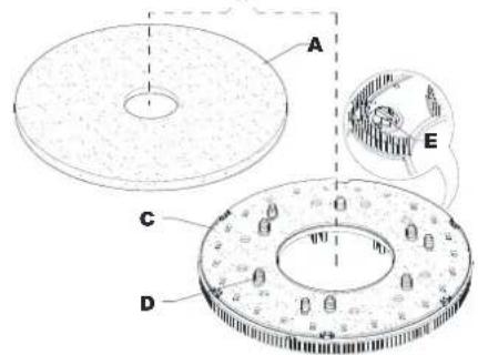
Afbeelding 5


Afbeelding 7
natural_image
Blue circular icon with a faucet symbol and four dot columns on the right (no text or numbers)natural_image
Blue circular icon with a beaker and three dots, next to two smaller dots (no text or symbols)| Percentage reinigingsmiddel | ||
| Lev.0 | Lev.1 | Lev.2 |
| UIT | 0,40%1:250 | 0,80%1:125 |
Afbeelding 11
Extra vermogen-knop
FORMÅL OG INNHOLD
MASKINSTRUKTUR (forts.)
- Nalkrok (T)
- Batterilader
- Elektromagnetisk bremse läse-/opplåsingsspake
- Avfallssamlingstank (T)
- Sugesystemmotor
- Sugegitter med automatisk lukking
- Batterier
- Avtakbar vannpåfyllingsslange (T)
- Frontfyller på løsningstank
- Kork til frontfyller på løsningstank (T)
- EcoFlex rengjøringsmiddelkanne
- Frontlys/Frontlys med laser (*)
- Frontpanel
-
Justeringsknott for kjøring rett fremover
-
Skivekostdekk
- Enkeltkost-skive
- REV-dekk
- REV-kost
- Dobbeltskive kostedekk
- Dobbeltskive kost
- Sidekrok for sylidenderkost
- Sylinderformet kost
- Sylidenderkostdekk

KONTROLLPANEL
- Hastighetsbryter (T)
- Overskrift
- Meldingsområde
- Forhåndsinnstilt navn
- Informasjonsfelt
- Statusområde
- Superfunksjons-knapp (T)
- Foroverspak
- Klokke
- Knapp for vannivå (kun i manuell modus)
- Graf over batterinivå
- Reversspak
- Knapp for vaskemiddelnivå (kun i manuell modus)
- Start/stopp/valg-knapp
- Av-/på-knapp
-
Nødstoppknapp
-
Knapp for dekktrykk (kun i manuell modus)
- Graf over vannivå
- Vakuumknapp (kun i manuell modus og vakuummodus)
- Smart-bryter (T)
- Menyknapp
- Type-C
- USB-A
- Klikk av-/på-modus for kost (kun for maskin med kosteskive)
- Kun vakuummodus
- Manuell modus
- Forhåndsinnstilt modus 1
- Forhåndsinnstilt modus 2
- Flere forhåndstinnstillinger
(T) Blåfarget berøringspunkt
BRUK/DRIFT

ADVARSEL!
Figur 1
BATTERIKONTROLL/INNSETTING PÅ NY MASKIN

ADVARSEL!

Figur 4

Figur 5
Figur 6
Montere nal
Figur 7
natural_image
Blue circular icon with a faucet symbol and three dots on the right side (no text or numbers)| Versjon | Verdier for løsningsstrøm (cl/meter) | Full løsningsstrømmodus (liter/minutt) må aktiveres av en overordnet bruker. | |||
| Lev.0 | Lev.1 | Lev.2 | Lev.3 | Lev.4 | |
| Skive | AV | 0,75 | 1,5 | 3,0 | 3,7 liter/minutt |
| REV | AV | 0,38 | 0,75 | 1,5 | |
| Dobbelt skive | AV | 0,90 | 1,8 | 3,6 | |
| Sylinderformet | AV | 1,0 | 1,83 | 2,8 | |
Figur 9
natural_image
Blue circular icon with a beaker and three dots, next to two smaller dots (no text or symbols)| Prosentandel med vaskemiddel | ||
| Lev.0 | Lev.1 | Lev.2 |
| AV | 0,40%1:250 | 0,80%1:125 |
Prosentandel med vaskemiddel
Figur 11
Superfunksjonsknapp
Trykk på superfunksjonsknappen (54) när du trenger sterkere vaskekraft midlertidig.
TABELL FOR FASTLAGT VEDLIKEHOLD
CEL I ZAWARTOŚĆ PRZEWODNIKA
OPIS MASZYNY BUDOWA MASZYNY

PANEL STEROWANIA
Rys. 1
KONTROLA I KONFIGURACJA AKUMULATORÓW W NOWEJ MASZYNIE

OSTRZEŻENIE!

Rys. 5


Rys. 7
WŁĄCZANIE I WYŁĄCZANIE MASZYNY
natural_image
Blue circular icon with a faucet symbol and three dot columns on black background (no text or symbols)natural_image
Blue circular icon with a beaker and three dots, next to two smaller dots (no text or symbols)FINALIDADE E CONTEÚDOS DO GUIA
PAINEL DE CONTROLO
Figura 1

Figura 5

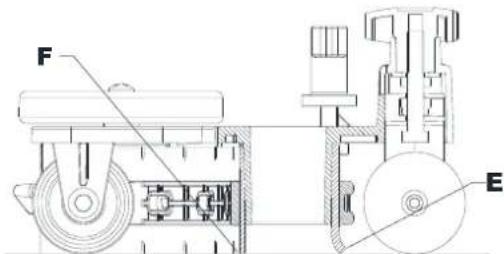
Figura 7
natural_image
Blue circular icon with a faucet symbol and three vertical dot columns on the right (no text or symbols)natural_image
Blue circular icon with a beaker symbol inside, next to two dark dots (no text or symbols)| Percentagem de detergente | ||
| Lev.0 | Lev.1 | Lev.2 |
| DESLIGADO | 0,40%1:250 | 0,80%1:125 |
Figura 11
CONTINUTUL ŞI SCOPUL GHIDULUI
STRUCTURA UTILAJULUI (Continuare)

PANOU DE COMANDĂ
Figura 1
VERIFICARE/SETARE BATERII PE O NOUĂ MAŞINĂ
AVERTISMENT!

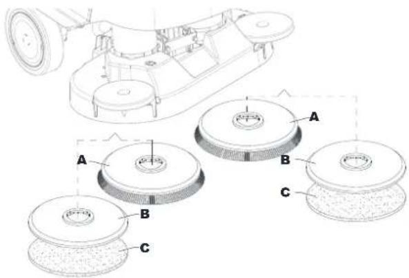
Figura 5
Montarea/demontarea periei (sistem cilindric)

Figura 7
natural_image
Blue circular icon with a faucet symbol and three vertical dot columns on the right (no text or symbols)natural_image
Blue circular icon with a beaker and three dots, next to two smaller dots (no text or symbols)| Procentul de detergent | ||
| Lev.0 | Lev.1 | Lev.2 |
| OPRIT | 0,40%1:250 | 0,80%1:125 |
Figura 11
ПАНЕЛЬ УПРАВЛЕНИЯ
Рис. 1

Рис. 4

Рис. 5

Установка швабры
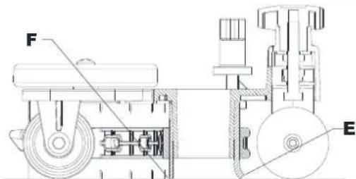
Рис. 7
natural_image
Blue circular icon with a faucet symbol and three dots on the right side (no text or numbers)natural_image
Blue circular icon with a beaker symbol inside, next to two dark dots (no text or symbols)CIEL' A OBSAH PRÍRUČKY
KONŠTRUKCIA STROJA (pokračovanie)
OVLÁDACÍ PANEL
Obrázok číslo 1
KONTROLA/NASTAVENIE BATÉRIE NA NOVOM STROJI
VAROVANIE!

natural_image
Technical line drawing of a mechanical component with labeled parts (no readable text or symbols)
Obrázok číslo 5
Obrázok číslo 7
(Pre stroje bez systému EcoFlex)
natural_image
Blue circular icon with a faucet symbol and three vertical dot columns on the right (no text or numbers)| Verzia | Hodnoty prietoku roztoku (cl/meter) | Režim plného prietoku roztoku (liter/minúta) vyžaduje, aby ho povolil kontrolór. | |||
| Lev.0 | Lev.1 | Lev.2 | Lev.3 | Lev.4 | |
| Kotúč | VYP | 0,75 | 1,5 | 3,0 | 3,7 l/min |
| REV | VYP | 0,38 | 0,75 | 1,5 | |
| Dvojitý kotúč | VYP | 0,90 | 1,8 | 3,6 | |
| Valcovitá | VYP | 1,0 | 1,83 | 2,8 | |
Obrázok číslo 9
natural_image
Blue circular icon with a beaker symbol inside, next to two dark dots (no text or symbols)| Percento čistíaceho prostriedku | ||
| Lev.0 | Lev.1 | Lev.2 |
| VYP | 0,40%1:250 | 0,80%1:125 |
Obrázok číslo 11
AK JE STROJ DLHO NEČINNÝ
NAMEN IN VSEBINA NAVODIL

NADZORNA PLOŠČA
Slika 1
PREVERJANJE/NASTAVLJANJE AKUMULATORJA NA NOVEM STROJU
OPOZORILO!

Slika 5
Slika 7
natural_image
Blue circular icon with a faucet symbol and three vertical dot columns on black background (no text or symbols)| Različica | Vrednosti pretoka raztopine (cl/meter) | Način polnega pretoka raztopine (liter/minuto) zahteva odobritev s strani uporabnika nadzornika. | |||
| Lev.0 | Lev.1 | Lev.2 | Lev.3 | Lev.4 | |
| Disk | IZKLOPLJENO | 0,75 | 1,5 | 3,0 | 3,7 litrov/minuto |
| REV | IZKLOPLJENO | 0,38 | 0,75 | 1,5 | |
| Dvojni disk | IZKLOPLJENO | 0,90 | 1,8 | 3,6 | |
| Cilindričen | IZKLOPLJENO | 1,0 | 1,83 | 2,8 | |
Slika 9
natural_image
Simple line icon of a laboratory flask inside a circle, with two dots beside it (no text or symbols)| Odstotek čistila | ||
| Lev.0 | Lev.1 | Lev.2 |
| IZKLOPLJ | 0,40% | 0,80% |
| ENO | 1:250 | 1:125 |
Slika 11
GUIDENS SYFTE OCH INNEHÅLL
SYMBOLER SOM FINNS I DENNA MANUAL

FARA!

KONTROLLPANEL
Figur 1
BATTERIKONTROLL/SLÅ PÅ EN NY MASKIN
WARNING!

Figur 5
Installation av gummiskrapa

Figur 7
natural_image
Blue circular icon with a faucet symbol and three vertical dot columns on black background (no text or symbols)natural_image
Blue circular icon with a beaker symbol inside, next to two dark dots (no text or symbols)| Procentandel rengöringsmedel | ||
| Lev.0 | Lev.1 | Lev.2 |
| AV | 0,40 % 1:250 | 0,80 % 1:125 |
Procentandel rengöringsmedel
Figur 11
KILAVUZUN AMACI VE İÇERİĞİ

KONTROL PANELİ
Şekil 1
YENİ MAKİNEDE AKÜ KONTROLÜ/AYARI

UYARI!
Şekil 5
Şekil 7
natural_image
Blue circular icon with a faucet symbol and vertical dot pattern (no text or numbers)natural_image
Simple line icon of a laboratory flask inside a circle, with two dots beside it (no text or symbols)Nilfisk Canada Company
Tel.: (+1) 800-668-8400
www.nilfisk.ca
CHILE
Nilfisk S.A. (Comercial KCS Ltda)
Nilfisk Middle East Branch
Tel.: (+971) (0) 655-78813
www.nilfisk.com
UNITED KINGDOM
Nilfisk Ltd
Tel: (+44) (0) 1768 868995
www.nilfisk.co.uk
UNITED STATES
Nilfisk, Inc.
Tel.: (+1) 800-989-2235
www.nilfisk.com
VIETNAM
Nilfisk Vietnam
Tel.: (+84) 761 5642
www.nilfisk.com