HM 2620 E KF SET - Heat gun STEINEL - Free user manual and instructions
Find the device manual for free HM 2620 E KF SET STEINEL in PDF.

| Product type | Heat gun |
| Brand | Steinel |
| Model | HM 2620 E KF SET |
| Power | 2300 W |
| Voltage | 220-230 V, 50/60 Hz |
| Temperature range | 50 °C to 700 °C, continuously adjustable |
| Air flow rate | 150 to 500 l/min, continuously adjustable |
| Weight (without cable) | 0.84 kg |
| Cable length | 3.0 m |
| Air nozzle diameter | 30 mm |
| LCD display | Yes |
| Main functions | Continuous temperature and flow adjustment, 4 preset programs, memory function, restart protection, residual heat display |
| Included accessories | Round nozzles (5, 10 mm), angled flat nozzles, pressure rollers, welding shoes, etc. |
| Maintenance and cleaning | Washable micro dust filter, power cord replacement without opening the housing |
| Safety | Thermal protection, restart safety, double insulation (class II) |
| Spare parts and repairability | Interchangeable power cord, plug-in heating element, replaceable filter |
| Motor lifetime | Approximately 10,000 hours |
| Heating element lifetime | Approximately 800 hours |
| Noise level | ≤ 70 dB(A) |
| Manufacturer's warranty | 1 year for hot air products |
Frequently Asked Questions - HM 2620 E KF SET STEINEL
User questions about HM 2620 E KF SET STEINEL
0 question about this device. Answer the ones you know or ask your own.
Ask a new question about this device
Download the instructions for your Heat gun in PDF format for free! Find your manual HM 2620 E KF SET - STEINEL and take your electronic device back in hand. On this page are published all the documents necessary for the use of your device. HM 2620 E KF SET by STEINEL.
USER MANUAL HM 2620 E KF SET STEINEL
natural_image
Black electric shaver with visible model number 7 and brand logo (no text-heavy elements)DE
Inhalt
6. Reparatur
Kabelwechsel
natural_image
Mechanical assembly diagram showing a cylindrical component being inserted into a housing (no text or symbols present)
natural_image
Diagram of a mechanical device with a cylindrical component being inserted, showing motion arrows (no text or symbols)
natural_image
Mechanical assembly diagram showing a pipe being inserted into a housing with arrows indicating motion (no text or symbols)
natural_image
Mechanical assembly diagram showing a cylindrical component being inserted into a housing (no text or symbols present)natural_image
Black-and-white collage showing hands using different tools: a power tool, a handheld tool, a battery pack, and a smiley face (no visible text or symbols)- About this document 23
- General safety precautions 23
- Device elements 26
- Commissioning 28
- Maintenance 31
- Repair 32
- Applications 35
- Disposal 37
- Declaration of conformity 37
- Manufacturer's warranty 38
- Technical specifications 41
1. About this document
- Under copyright. Reproduction either in whole or in part only with our consent.
- Subject to change in the interest of technical progress.

Hazard warning!

Warning of hazards due to environmental influences!

Beware of toxic gases and fire hazards!
Warning of hazards from electricity!
2. General safety precautions

Failure to observe these operating instructions presents hazards!
These instructions contain important information on the safe use of this product. Particular attention is drawn to potential hazards. Failure to observe this information may lead to death or serious injuries.
- Read instructions carefully.
- Follow safety advice.
- Keep instructions within easy reach.
When using power tools, the following basic safety measures must be observed to protect against electric shock, risk of injury and fire. If the appliance is not handled with care, a fire may break out or people may be injured. Check the appliance for any damage (mains connection cable, housing, etc.) before commissioning and do not operate the appliance if it is damaged.
When using power tools, the following basic safety measures must be observed to protect against electric shock, risk of injury and fire. If the appliance is not handled with care, a fire may break out or people may be injured. Check the appliance for any damage (mains connection cable, housing, etc.) before commissioning and do not operate the appliance if it is damaged.
Do not operate the appliance unsupervised. Children should be supervised to ensure that they do not play with the appliance.
Initial commissioning
Some smoke may be emitted on first use. The smoke is caused by binding agents that are released from the insulating foil of the heater by the heat during the first use. The appliance should be placed on its base to ensure that smoke is emitted quickly. The working area should be well ventilated during the first use. The smoke emitted is not harmful!
Warning of hazards due to environmental influences!
- Do not expose power tools to rain. Do not use power tools when damp or in a damp or wet environment.
- Take care when using the appliances in the vicinity of flammable materials.
- Do not aim at the same spot for long periods of time.
- Do not use in the presence of an explosive atmosphere.
- Heat can be conducted to combustible materials that are covered.
Warning of hazards from electricity!
- Avoid coming into contact with earthed objects, such as pipes, radiators, cookers or refrigerators.
- Do not leave the tool unattended while it is in operation.

Store your tools in a safe place.
- After use, set the tool down on its standing surface and let it cool before putting it away.
- When not in use, tools must be stored in a dry, locked room out of children's reach.
- This tool may be used by children aged 8 or above and by persons with reduced physical, sensory or mental capabilities or lack of experience and knowledge if they are supervised or have been given instructions on how to use the tool safely and understand the hazards involved.
- Do not allow children to play with the tool.
- Children are not allowed to clean or carry out maintenance work on the tool without supervision.

Do not overload your tools!
- You work better and more safely in the specified power range.
- Do not carry the tool by the cable and do not use it to pull the plug out of the socket.
- Protect the cable from heat, oil and sharp edges.

Beware of toxic gases and fire hazards!
- For your own safety, only use accessories and attachments that are specified in the operating instructions or recommended or specified by the tool manufacturer.
- The use of tools or accessories other than those recommended in the operating instructions or in the catalog may pose a risk of personal injury to you.

Repairs only by a qualified electrician
• This power tool complies with the relevant safety regulations.
- Repairs should only be performed by a qualified electrician. Otherwise the user may run the risk of accidents.
3. Device elements
3.1


1 Stainless steel outlet nozzle
2 Removable guard sleeve
3 Air inlet (including fine dust filter)
4 Soft coating for non-slip standing
5 LCD display
6 Removable cap for mounting HM Scan PRO temperature scanner
7 Heavy-duty rubber-insulated power cord
8 ON/OFF button
9 Joystick (for setting airflow rate and temperature)
10 Button for airflow rate mode
11 Programme selector button and memory button
12 Residual heat indicator
13 Soft grip handle for comfortable operation
14 Replaceable mains power cord
Accessoires
1 Round nozzle, 5 mm
2 Round nozzle, 10 mm
3 Round nozzle, 5 mm, extended
4 Flat angled nozzle, 20 x 2 mm
Flat angled nozzle, 20 x 2 mm, straight
5 Flat angled nozzle, 40 x 2 mm
6 Flat angled nozzle, 30 x 2 mm
7 Flat angled nozzle, 40 x 2 mm, perforated
8 Flat nozzle, 60 x 2 mm, for bitumen
9 Pressure roller, 50 mm
10 Pressure roller, 35 mm
11 Tarpaulin shears
12 Kehlfix
13Weld slide
14 Welding nozzle
15 Fast welding nozzle, 3 mm
16 Fast welding nozzle, 4 mm
17 Fast welding nozzle, 5 mm
18 Fast welding nozzle, 3 mm, with narrow air slot
19 Fast welding nozzle, 4 mm, with narrow air slot
20 Fast welding nozzle, 5 mm, with narrow air slot
21 Jointing plane
22 Quarter moon knife
23 Soldering reflector nozzle
24 Reflector nozzle, 20 mm
25 Reflector nozzle, 35 mm
26 Sieve reflector nozzle, 30 x 20 mm
27 Sieve reflector nozzle, 50 x 35 mm
28 Shell reflector nozzle
29 HM Scan PRO
For your safety:
- The tool is protected from overheating.
- The thermal cut-out completely shuts down the tools if it is overloaded.
4. Commissioning
Please note: The distance from the object you are working on depends on material and intended method of working. Always try out the airflow and temperature on a test piece first. Using the attachable accessory nozzles (see accessories page on the cover) the flow of hot air can be controlled with maximum precision.
Take care when changing hot nozzles! When using the hot air tool in the self-resting position, make sure it is standing on a stable, non-slip and clean surface.
Switch-on procedures generate short-term voltage drops. In unfavourable grid conditions, adverse effects can occur on other devices. With grid impedances of less than 0.35 ohms, no disturbances are expected.
1. Operation
The tool is switched on and off at the ON/OFF button 8 on the back of the grip handle. The joystick 9 is used for controlling temperature and airflow or fan speed.
2. Setting the temperature
Temperature can be infinitely varied over a range of 50 – 700 °C at the joystick on the control panel with LCD display. The actual temperature is measured at the hot air outlet nozzle and indicated on the display. The joystick is used as an input button with plus/minus function. Briefly pressing the “+/-” joystick increases or reduces the temperature setting in 10 ° steps. Keeping the joystick pressed speeds up the temperature setting process. Once the temperature has been set, the tool takes a few seconds to reach temperature (depending on speed/airflow). The temperature setting selected is shown on the display for 3 seconds. The display then shows the current actual temperature. The “°C/°F” symbol continues to flash until the selected temperature is reached.
If you want to alter the setting, simply press the joystick again to increase or reduce the temperature. After switching off, the hot air tool stays in the last setting.
3. Setting airflow rate
To change the airflow rate, first press the button for airflow mode 10; the fan symbol flashes. Now use the joystick to set the airflow rate. The airflow rate setting mode automatically closes if the airflow rate setting is not changed within 5 sec. Pressing the airflow button again after setting the airflow rate immediately closes the airflow rate setting mode. The airflow rate can be varied from a minimum of 150 l/min to a maximum of 500 l/min.
4. Programming mode (P)
Four programmes are factory-set for the most common types of work. Press button “P” for programming mode. Number 1 is displayed for programme 1. Continuing to press the programme button will take you to programmes 2–4. Pressing the button again will return the tool to normal operation.
Preset programmes
| Program Temperature °C Air l/min. | ||
| 1 250 °C aprox. 350 | ||
| 2 350 °C aprox. 400 | ||
| 3 450 °C aprox. 500 | ||
| 4 550 °C aprox. 400 | ||
5. Memory function (S)
The values selected for the four programmes can be changed and memorised at any time. To do this, first press the programme button “P” 11 until the display shows the programme you wish to change. Set the temperature and airflow rate you require. Memory symbol on the LCD flashes to indicate that the user programme selected has been changed. To memorise this setting in the user programme selected, press and hold down the programme selector button. The memory symbol continues to flash for approx. 2 sec. The settings entered are saved once the memory symbol stays on all the time. To return to normal operation, press the programme button until the programme symbol disappears from the display.
Temperature measurement on the workpiece
We recommend the STEINEL HM Scan PRO temperature scanner for measuring the temperature at the workpiece.
5. Maintenance
GB
Fine dust filter
The HM 2620 E is supplied with a fine dust filter ^3 . To install it, undo the air inlet and insert the filter. To clean it (with compressed air), undo screws (a), take off cover and remove filter.
6. Repair
Chaning the power cord
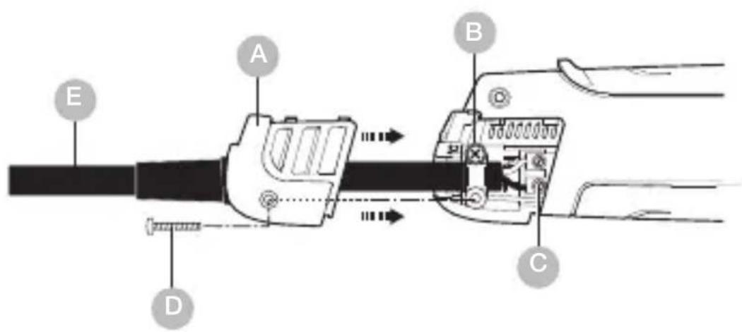
If the power cord is damaged, it can easily be changed without opening the casing.
6.1
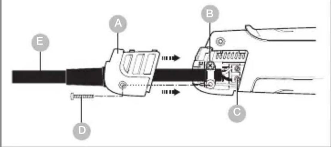
Important! Disconnect tool from power supply.
- Undo screw D and pull off cover cap A.
- Release cable grip B.
- Undo mains terminals C.
- Pull out cable E.
- Insert new cable and secure in reverse order (1. Firmly screw down mains terminals etc.).
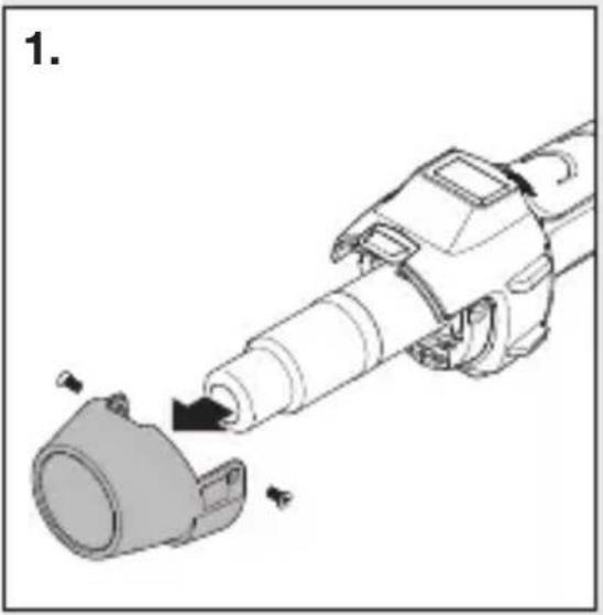
Changing the heating element
GB
The plug-in heating element in the HM 2620 E can be changed in a matter of seconds.
natural_image
Mechanical assembly diagram showing a cylindrical component being inserted into a housing (no text or symbols present)
natural_image
Diagram of a mechanical device with a cylindrical component being inserted, showing motion arrows (no text or symbols)
natural_image
Mechanical assembly diagram showing a pipe being inserted into a housing with arrows indicating motion (no text or symbols)
natural_image
Mechanical assembly diagram showing a cylindrical component being inserted into a housing (no text or symbols present)- Important! Disconnect tool from power supply.
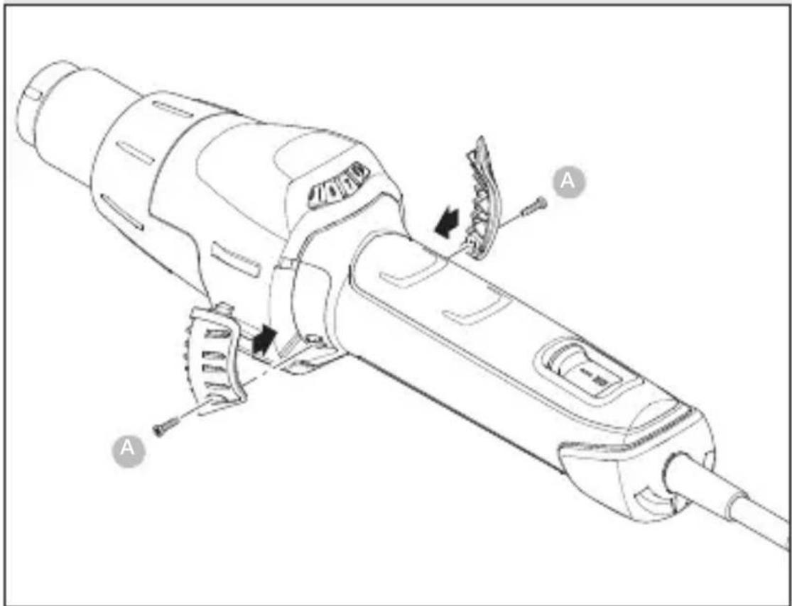
- Undo guard sleeve screws (Fig. 1).
- Remove guard sleeve (Fig. 1).
- Undo 4 screws at the end of the hot air outlet nozzle (Fig. 2).
- Detach heating element and replace it with a new one (Fig. 2/3).
- Firmly screw heating element into place (Fig. 3).
- Firmly screw guard sleeve back on (Fig. 4).
Other functions
Restart protection
Restart protection prevents the hot air tool from starting after an interruption in the power supply. The hot air tool is only ready for operation again after switching it on at the ON/OFF button 8.
LOC function
To avoid altering the chosen settings unintentionally, the HM 2620 E comes with a Lockable Override Control Function (LOC). To find out how to set the LOC function, please contact our Service Department on.
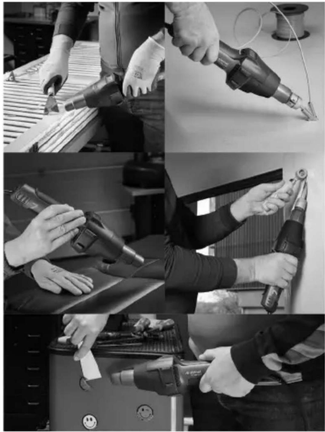
7. Applications
GB
Here are some of the applications you can use STEINEL hot air tools for.
7.1
natural_image
Black-and-white collage showing hands using different tools to adjust or install a component, including a power tool and a battery pack (no visible text or symbols)- Welding bitumen.
– Welding tarpaulins and films. -
Welding PVC floor coverings and linoleum.
-
Working rigid thermoplastic materials in plastics and tank construction.
- Shaping thermoplastics.
– Drying wet surfaces. - Activating and removing glues and hot-melt adhesives.
– Drying and heating processes of all kinds.
Guide for selecting the right type of welding rod for welding plastics
Material / Applications / Characteristic signs
- Rigid PVC / Pipes, fittings, tiles, structural sections, technical mouldings, 300 °C welding temperature / Chars when held in flame, pungent odour; crashing sound
- Rigid PE (HDPE) Polyethylene / Tubs, baskets, canisters, insulating material, piping, 300 °C welding temperature / Light yellow flame, drips continue to burn, smells of a candle being extinguished; crashing sound
- PP Polypropylene / High-temperature drainpipes, seat buckets, packagings, automotive parts, 250 °C welding temperature / Bright flame with a blue core, drips continue to burn, pungent odour; crashing sound
- ABS / Automotive parts, equipment enclosures, cases 350 °C welding temperature / Black, fluffy smoke; sweet odour; crashing sound
8. Disposal
Electrical and electronic equipment, accessories and packaging must be recycled in an environmentally compatible manner.
Do not dispose of electrical and electronic equipment as domestic waste.
EU countries only:
Under the current European Directive on Waste Electrical and Electronic Equipment and its implementation in national law, electrical and electronic equipment no longer suitable for use must be collected separately and recycled in an environmentally compatible manner.
9. Declaration of conformity
STEINEL GmbH hereby declares that the hot air blower HM 2620 E complies with Directive 2006/42/EC.
The full text of the EU Declaration of Conformity is available at the following Internet address:
www.steinel.de
10. Manufacturer's warranty
Manufacturer's warranty of STEINEL GmbH, Diesel-strasse 80-84, DE-33442 Herzebrock-Clarholz, Germany All STEINEL products meet the highest quality standards. For this reason, we, the manufacturer, are pleased to provide you, the customer, with a warranty under the following terms and conditions:
The warranty covers the absence of deficiencies which are proven to be the result of a material defect or fault in manufacturing and which are reported to us immediately after detection and within the warranty period. The warranty shall cover all STEINEL Professional products sold and used in Germany.
Our warranty cover for consumers
The provisions below apply to consumers. A consumer is any natural person who, on entering into the purchase transaction, neither acts in exercising their commercial nor their self-employed activity.
You can opt for warranty cover in the form of repair or replacement which will be provided free of charge (if applicable, in the form of a successor model of the same or higher quality) or in the form of a credit note.
In the case of sensors, floodlights, outdoor and indoor lights, the warranty period for the STEINEL Professional product you have purchased is: 5 years
for hot-air and hot-melt gluing products: 1 year
in each case from the date on which the product was purchased.
We shall bear the shipping costs but not the transport risks involved in return shipment.
Our warranty cover for entrepreneurs
The provisions below apply to entrepreneurs. Entrepreneur is a natural or legal person or partnership with legal personality who or which, on entering into the purchase transaction, acts in exercising their or its commercial or self-employed activity.
We have the option of providing warranty cover by rectifying deficiencies free of charge, replacing a product free of charge (if applicable, in the form of a successor model of the same or higher quality) or by issuing a credit note. In the case of sensors, floodlights, outdoor and indoor lights, the warranty period for the STEINEL Professional product you have purchased is: 5 years
for hot-air and hot-melt gluing products: 1 year in each case from the date on which the product was purchased.
Within the scope of warranty cover, we shall not bear your expenses accruing from subsequent fulfillment nor shall we bear your expenses for removing the defective product and installing a replacement product.
Statutory rights accruing from defects, gratuitousness
The warranty cover described here shall be applicable in addition to the statutory rights of warranty – including special consumer protection provisions – and shall not restrict or replace them. Exercising your statutory rights in the event of defects is gratuitous.
Exemptions from the warranty
All replaceable lamps are expressly excluded from this warranty.
In addition to this, the warranty shall not cover:
– any wear resulting from use or any other natural wear of product parts or any deficiencies in the STEINEL Professional product that are attributable to wear caused by use or other natural wear,
– any improper or non-intended use of the product or any failure to observe the operating instructions,
– any unauthorised additions, alterations or other modifications to the product or any deficiencies attributable to the use of accessory,
– supplementary or replacement parts which are not genuine STEINEL parts,
– any maintenance or care of products that is not carried out in accordance with the operating instructions,
– any attachment or installation that is not in accordance with STEINEL’s installation instructions,
– any damage or loss occurring in transit.
Application of German law
The warranty shall be governed by German law excluding the United Nations Convention concerning the International Sale of Goods (CISG).
Making claims
If you wish to make a warranty claim, please send your product complete and carriage paid with the original receipt of purchase, which must show the date of purchase and product designation, either to your retailer or directly to us at STEINEL (UK) Ltd. – 25 Manasty Road, Axis Park, Orton Southgate, GB- Peterborough Cambs PE2 6UP United Kingdom. For this reason, we recommend that you keep your receipt of purchase in a safe place until the warranty period expires.
11. Technical specifications
- Voltage: 220 - 230 V, 50/60 Hz
- Output: 2,300 W max.
- Temperature: 50 - 700 °C, continuously variable
- Airflow rate: 150 - 500 l/ min, continuously variable
– Air pressure: 4,000 Pa
– Delivery nozzle ∅: 30 mm, using Professional nozzles - Motor life: approx. 10,000 hrs.
- Heater life: approx. 800 hrs.
- Residual heat indicator: yes
- Power cord: H07 RN-F 2X1 3,0 M
- Protection class: //
- Thermal cut-out: yes
- Emission sound pressure level: ≤ 70 dB (A)
- Total vibration value: ≤ 2.5m / s^2 I K = 0.08m / s^2
- Weight without power cord: 0.84 kg
FR
Sommaire
6. Réparation
natural_image
Mechanical assembly diagram showing a cylindrical component being inserted into a housing (no text or symbols present)
natural_image
Diagram of a mechanical device with a cylindrical component being inserted, showing internal components and motion arrows (no text or symbols)
natural_image
Mechanical assembly diagram showing a pipe being inserted into a housing (no text or symbols visible)
natural_image
Mechanical assembly diagram showing a cylindrical component being inserted into a housing (no text or symbols present)6. Reparatie
natural_image
Mechanical assembly diagram showing a cylindrical component being inserted into a housing (no text or symbols present)
natural_image
Diagram of a mechanical device with a cylindrical component being inserted, showing motion arrows (no text or symbols)
natural_image
Mechanical assembly diagram showing a pipe being inserted into a housing with arrows indicating motion (no text or symbols)
natural_image
Mechanical assembly diagram showing a cylindrical component being inserted into a housing (no text or symbols present)natural_image
Four-panel black-and-white photo collage showing hands using different tools: soldering, welding, cleaning, and cleaning (no visible text or symbols)6. Riparazione
natural_image
Mechanical assembly diagram showing a tool interacting with a cylindrical component (no text or symbols present)
natural_image
Diagram of a mechanical component being inserted into a cylindrical shaft, showing internal components and motion arrows (no text or symbols)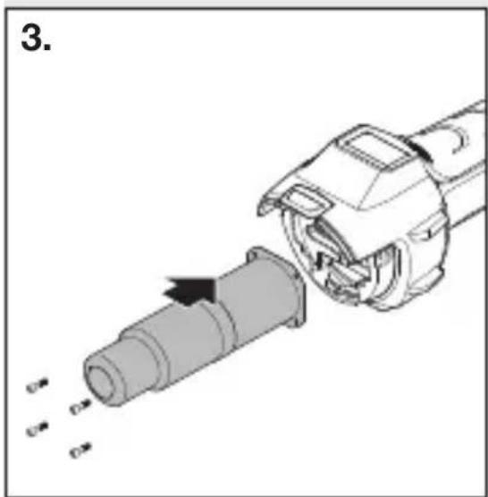
natural_image
Mechanical assembly diagram showing a pipe being inserted into a cylindrical component (no text or symbols visible)
natural_image
Mechanical assembly diagram showing a tool interacting with a mechanical component (no text or symbols visible)natural_image
Black-and-white collage showing hands using different types of power tools, including a drill pen, tool holder, and digital device (no visible text or symbols)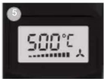
6. Reparación
Cambio del cable
natural_image
Mechanical assembly diagram showing a cylindrical component being inserted into a housing (no text or symbols present)
natural_image
Diagram of a mechanical device with a cylindrical component being inserted, showing motion arrows (no text or symbols)
natural_image
Mechanical assembly diagram showing a pipe being inserted into a housing with arrows indicating motion (no text or symbols)
natural_image
Mechanical assembly diagram showing a cylindrical component being inserted into a housing (no text or symbols present)
6. Reparação
natural_image
Mechanical assembly diagram showing a cylindrical component being inserted into a housing (no text or symbols present)
natural_image
Diagram of a mechanical device with a cylindrical component being inserted, showing motion arrows (no text or symbols)
natural_image
Mechanical assembly diagram showing a pipe being inserted into a housing with arrows indicating motion (no text or symbols)
natural_image
Mechanical assembly diagram showing a cylindrical component being inserted into a housing (no text or symbols present)natural_image
Black-and-white collage showing hands using different tools: a power tool, a handheld tool, a battery pack, and a smiley face (no visible text or symbols)- Soldar betume.
- Soldar oleados e películas.
- Soldar pavimentos em PVC e linóleo.
6. Reparation
Byte av kabel
natural_image
Mechanical assembly diagram showing a tool interacting with a mechanical component (no text or symbols visible)
natural_image
Diagram of a mechanical device with a cylindrical component being inserted, showing motion arrows (no text or symbols)
natural_image
Mechanical assembly diagram showing a pipe being inserted into a housing with arrows indicating motion (no text or symbols)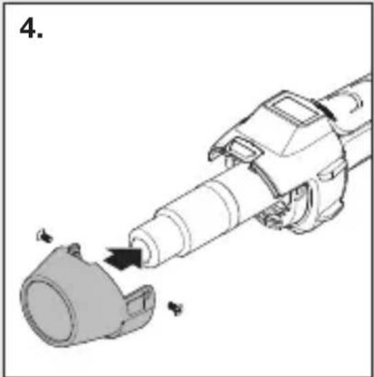
natural_image
Diagram of a mechanical device with a cylindrical component being inserted, showing motion arrows (no text or symbols)6. Reparation
natural_image
Mechanical assembly diagram showing a tool interacting with a mechanical component (no text or symbols visible)
natural_image
Diagram of a mechanical device with a cylindrical component being inserted, showing motion arrows (no text or symbols)
natural_image
Mechanical assembly diagram showing a pipe being inserted into a housing with arrows indicating motion (no text or symbols)
natural_image
Diagram of a mechanical device with a cylindrical component being inserted, showing motion arrows (no text or symbols)natural_image
Black-and-white collage showing hands using different tools to adjust or install a component, including a power tool and a drill bit (no visible text or symbols)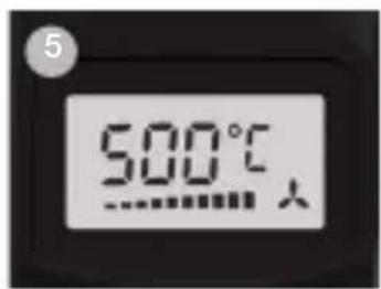
6. Korjaaminen
Johdon vaihtaminen
natural_image
Mechanical assembly diagram showing a cylindrical component being inserted into a housing (no text or symbols present)
natural_image
Diagram of a mechanical device with a cylindrical component being inserted, showing internal components and motion arrows (no text or symbols)
natural_image
Mechanical assembly diagram showing a pipe being inserted into a housing, with arrows indicating direction (no text or symbols present)
natural_image
Mechanical assembly diagram showing a cylindrical component being inserted into a housing (no text or symbols present)natural_image
Black-and-white collage showing hands using different tools to adjust or install a component, including a power tool and a drill bit (no visible text or symbols)6. Reparasjon
Skifte av ledning
natural_image
Mechanical assembly diagram showing a tool interacting with a mechanical component (no text or symbols visible)
natural_image
Mechanical assembly diagram showing a tool interacting with a cylindrical component (no text or symbols visible)
natural_image
Mechanical assembly diagram showing a pipe being inserted into a housing with arrows indicating motion (no text or symbols)
natural_image
Diagram of a mechanical device with a cylindrical component being inserted, showing motion arrows (no text or symbols)- Viktig! Påse at apparatet er uten strøm.
- Løsne skruen fra beskyttelsesrøret (Fig. 1).
- Ta av beskyttelsesrøret (Fig. 1).
- Løsne de fire skruene på enden av luftrøret (Fig. 2).
- Trekk ut varmeelementet og skift det ut med et nytt varmeelement (Fig. 2/3).
- Skru på varmeelementet igjen (Fig. 3).
- Skru beskyttelsesrøret på (Fig. 4).
natural_image
Black-and-white collage showing hands using different types of power tools, including a drill pen, tool holder, and digital device (no visible text or symbols)GR
6. Επισκευή
natural_image
Mechanical assembly diagram showing a cylindrical component being inserted into a housing (no text or symbols present)
natural_image
Diagram of a mechanical device with a cylindrical component being inserted, showing motion arrows (no text or symbols)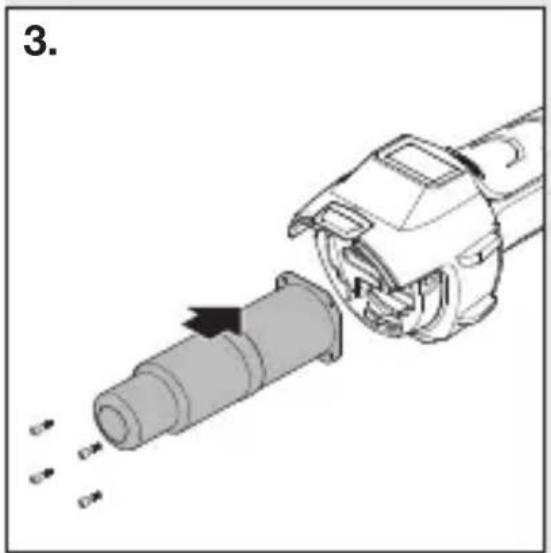
natural_image
Mechanical assembly diagram showing a pipe being inserted into a housing with arrows indicating motion (no text or symbols)
natural_image
Mechanical assembly diagram showing a cylindrical component being inserted into a housing (no text or symbols present)natural_image
Black-and-white collage showing hands using different tools: a power tool, a handheld tool, and a battery pack (no visible text or symbols)TR
6. Onarım
Kablo değişimi
natural_image
Mechanical assembly diagram showing a tool interacting with a mechanical component (no text or symbols visible)
natural_image
Mechanical assembly diagram showing a tool interacting with a cylindrical component (no text or symbols visible)
natural_image
Mechanical assembly diagram showing a pipe being inserted into a housing, with arrows indicating motion direction (no text or symbols)
natural_image
Diagram of a robotic arm with a mechanical component and directional arrow indicating motion (no text or symbols)natural_image
Four-panel black-and-white photo collage showing hands using different tools: soldering, welding, holding a tool, and cleaning a battery (no visible text or symbols)HU
6. Javítás
Kábelcsere
natural_image
Mechanical assembly diagram showing a cylindrical component being inserted into a housing (no text or symbols present)
natural_image
Diagram of a mechanical device with a cylindrical component being inserted, showing internal components and motion arrows (no text or symbols)
natural_image
Mechanical assembly diagram showing a pipe being inserted into a housing with arrows indicating motion (no text or symbols)
natural_image
Mechanical assembly diagram showing a cylindrical component being inserted into a housing (no text or symbols present)natural_image
Four-panel black-and-white photo collage showing hands using different tools: soldering, welding, holding a tool, and cleaning a battery (no visible text or symbols)
CZ
6. Oprava
Výměna kabelu
natural_image
Mechanical assembly diagram showing a cylindrical component being inserted into a housing (no text or symbols present)
natural_image
Diagram of a mechanical device with a cylindrical component being inserted, showing motion arrows (no text or symbols)
natural_image
Mechanical assembly diagram showing a pipe being inserted into a housing with arrows indicating motion (no text or symbols)
natural_image
Mechanical assembly diagram showing a tool interacting with a component (no text or symbols visible)natural_image
Black-and-white collage showing hands using different tools to adjust or install a component, including a power tool and a battery pack (no visible text or symbols)SK
6. Oprava
Výmena kábla
natural_image
Mechanical assembly diagram showing a tool interacting with a mechanical component (no text or symbols visible)
natural_image
Mechanical assembly diagram showing a tool interacting with a cylindrical component (no text or symbols visible)
natural_image
Mechanical assembly diagram showing a pipe being inserted into a housing with arrows indicating motion (no text or symbols)
natural_image
Diagram of a mechanical device with a cylindrical component being inserted, showing motion arrows (no text or symbols)natural_image
Black-and-white collage showing hands using different tools to adjust or install a component, including a power tool, a pen, and a battery pack (no visible text or symbols)– Zváranie bituménu.
– Zváranie plachtovín a fólií.
– Zváranie podlahových krytín z PVC a linolea.

PL
6. Naprawa
Wymiana kabla
natural_image
Mechanical assembly diagram showing a tool interacting with a mechanical component (no text or symbols visible)
natural_image
Mechanical assembly diagram showing a tool interacting with a cylindrical component (no text or symbols visible)
natural_image
Mechanical assembly diagram showing a pipe being inserted into a housing with arrows indicating motion (no text or symbols)
natural_image
Diagram of a robotic arm with a mechanical component and directional arrow indicating motion (no text or symbols)PL
natural_image
Black-and-white collage showing hands using different tools to adjust or install a component, including a power tool and a battery pack (no visible text or symbols)
4. Regim Programe (P)
6. Reparații
Schimbarea cablului
natural_image
Mechanical assembly diagram showing a tool interacting with a mechanical component (no text or symbols visible)
natural_image
Mechanical assembly diagram showing a disassembled cylindrical component being inserted into a motor (no text or symbols present)
natural_image
Mechanical assembly diagram showing a pipe being inserted into a housing with arrows indicating motion (no text or symbols)
natural_image
Diagram of a robotic arm with a mechanical component and directional arrow indicating motion (no text or symbols)natural_image
Black-and-white collage showing hands using different tools: a power tool, a handheld tool, a battery pack, and a smiley face (no visible text or symbols)6. Popravila
Menjava kabla
natural_image
Mechanical assembly diagram showing a cylindrical component being inserted into a housing (no text or symbols present)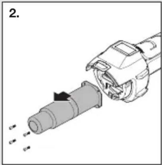
natural_image
Diagram of a mechanical device with a cylindrical component being inserted, showing internal components and motion arrows (no text or symbols)
natural_image
Mechanical assembly diagram showing a pipe being inserted into a housing (no text or symbols visible)
natural_image
Mechanical assembly diagram showing a cylindrical component being inserted into a housing (no text or symbols present)- Pomembno! Napravo odklopite od el. omrežja.
- Vijake odvijte od zaščitne cevi (Slika 1).
- Odstranite zaščitno cev (Slika 1).
- Odvijte 4 vijake na koncu izpihovalne cevi (Slika 2).
- Snemite grelec in ga zamenjajte z novim (Slika 2/3).
- Grelec ponovno privijačite (Slika 3).
- Ponovno namestite zaščitno cev (Slika 4).
Nadaljnje funkcije
Zaščita pred ponovnim zagonom
natural_image
Black-and-white collage showing hands using different tools: a power tool, a handheld tool, a battery pack, and a smiley face (no visible text or symbols)
6. Popravak
Zamjena kabela
Ako je mrežni kabel oštećen, može se jednostavno zamije- niti bez otvaranja kućišta:
6.1
natural_image
Mechanical assembly diagram showing a cylindrical component being inserted into a housing (no text or symbols present)
natural_image
Diagram of a mechanical device with a cylindrical component being inserted, showing internal components and motion arrows (no text or symbols)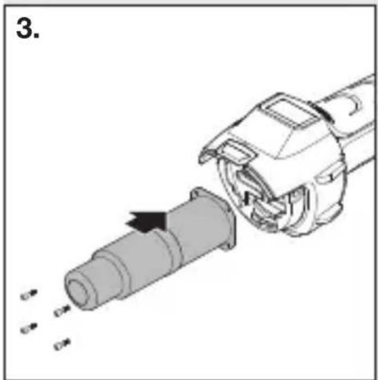
natural_image
Mechanical assembly diagram showing a pipe being inserted into a housing (no text or symbols visible)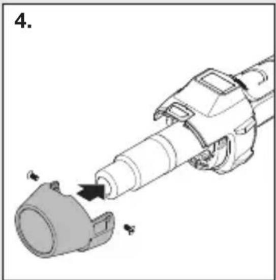
natural_image
Mechanical assembly diagram showing a cylindrical component being inserted into a housing (no text or symbols present)- Važno! Isključite uređaj iz strujne mreže.
- Odvrnite vijke sa zaštitne cijevi (Sl. 1).
- Skinite zaštitnu cijev (Sl. 1).
- Otpustite 4 vijka na kraju ispušne cijevi (Sl. 2).
- Skinite grijaći dio i zamijenite ga novim (Sl. 2/3).
- Ponovno pričvrstite grijaći dio (Sl. 3).
- Pričvrstite zaštitnu cijev (Sl. 4).
Ostale funkcije
natural_image
Black-and-white collage showing hands using different tools: a power tool, a handheld tool, a battery pack, and a smiley face (no visible text or symbols)– Zavarivanje bitumena.
– Zavarivanje folija i cerada.
– Zavarivanje PVC podnih obloga i linoleuma.
– Obrada svih termoplastičnih tvrdih materijala u proizvodnji plastike i spremnika.
– Preoblikovanje termoplastičnih umjetnih materijala.
– Sušenje vlažnih površina.
– Aktiviranje i skidanje ljepila i topivih ljepila
– Procesi sušenja i zagrijavanja svih vrsta.
Pomoć kod odabira ispravne žice za zavarivanje plastike
6. Remont
Kaabli vahetamine
natural_image
Mechanical assembly diagram showing a cylindrical component being inserted into a housing (no text or symbols present)
natural_image
Diagram of a mechanical device with a cylindrical component being inserted, showing motion arrows (no text or symbols)
natural_image
Mechanical assembly diagram showing a pipe being inserted into a housing with arrows indicating motion (no text or symbols)
natural_image
Mechanical assembly diagram showing a cylindrical component being inserted into a housing (no text or symbols present)natural_image
Black-and-white collage showing hands using different tools: a power tool, a handheld tool, a battery pack, and a smiley face (no visible text or symbols)
6. Remontas
Kabelio keitimas
natural_image
Mechanical assembly diagram showing a cylindrical component being inserted into a housing (no text or symbols present)
natural_image
Diagram of a mechanical device with a cylindrical component being inserted, showing motion arrows (no text or symbols)
natural_image
Mechanical assembly diagram showing a pipe being inserted into a housing with arrows indicating motion (no text or symbols)
natural_image
Mechanical assembly diagram showing a tool interacting with a component (no text or symbols visible)natural_image
Black-and-white collage showing hands using different tools: a power tool, a handheld tool, a battery pack, and a smiley face (no visible text or symbols)6. Remonts
Kabela nomaina
natural_image
Mechanical assembly diagram showing a cylindrical component being inserted into a housing (no text or symbols present)
natural_image
Diagram of a mechanical device with a cylindrical component being inserted, showing motion arrows (no text or symbols)
natural_image
Mechanical assembly diagram showing a pipe being inserted into a housing with arrows indicating motion (no text or symbols)
natural_image
Mechanical assembly diagram showing a tool interacting with a component (no text or symbols visible)natural_image
Black-and-white collage showing hands using different tools: a power tool, a handheld tool, a battery pack, and a smiley face (no visible text or symbols)6. Ремонт
Смяна на кабел
natural_image
Mechanical assembly diagram showing a cylindrical component being inserted into a housing (no text or symbols present)
natural_image
Diagram of a mechanical device with a cylindrical component being inserted, showing motion arrows (no text or symbols)
natural_image
Mechanical assembly diagram showing a pipe being inserted into a housing with arrows indicating motion (no text or symbols)
natural_image
Mechanical assembly diagram showing a cylindrical component being inserted into a housing (no text or symbols present)natural_image
Black-and-white collage showing hands using different tools: a power tool, a handheld tool, a battery pack, and a smiley face (no visible text or symbols)6. 维修
更换电缆
natural_image
Mechanical assembly diagram showing a tool interacting with a component (no text or symbols visible)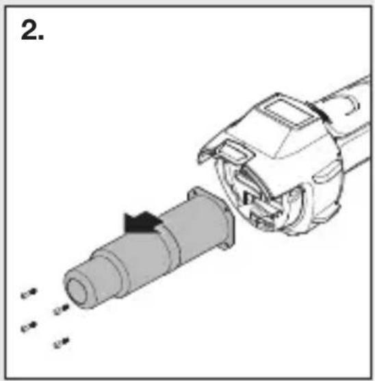
natural_image
Mechanical assembly diagram showing a tool interacting with a cylindrical component (no text or symbols visible)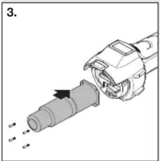
natural_image
Mechanical assembly diagram showing a cylindrical component being inserted into a motor (no text or symbols visible)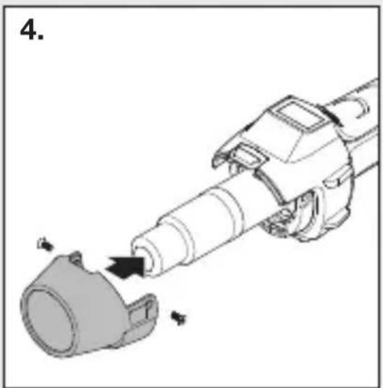
natural_image
Mechanical assembly diagram showing a tool interacting with a cylindrical component (no text or symbols present)natural_image
Black-and-white collage showing hands using different tools to adjust or install a component, including a drill pen and power tool (no visible text or symbols)6. Ремонт
natural_image
Mechanical assembly diagram showing a tool interacting with a cylindrical component (no text or symbols present)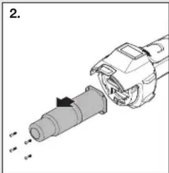
natural_image
Diagram of a mechanical device with a cylindrical component being inserted, showing internal components and motion arrows (no text or symbols)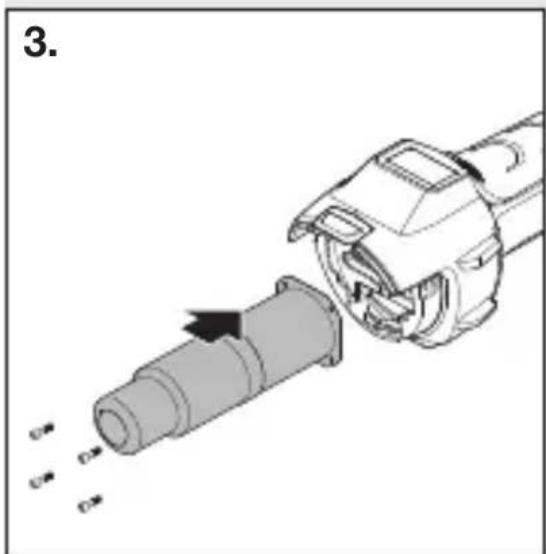
natural_image
Mechanical assembly diagram showing a pipe being inserted into a cylindrical component (no text or symbols visible)