HPM-01 - Drill MSW - Free user manual and instructions
Find the device manual for free HPM-01 MSW in PDF.

| Product type | Hydraulic punch |
| Model | MSW HPM-01 |
| Maximum production capacity | 8 tons |
| Punching diameter range | 22-60 mm |
| Maximum sheet thickness | 3 mm |
| Dimensions (L x W x H) | 170 x 405 x 170 mm |
| Weight | 5.3 kg |
| Power supply type | Manual hydraulic (piston pump) |
| Main functions | Making holes in sheets |
| Maintenance and cleaning | Clean external surfaces with a clean damp cloth, lubricate with rust-proof oil. Change the oil every year. |
| Safety | Do not use without die, do not pump after cylinder stops, do not hit the tool, keep couplers clean. |
| Spare parts and repairability | Contact the manufacturer/distributor to replace seal kits. Maintenance by a qualified technician. |
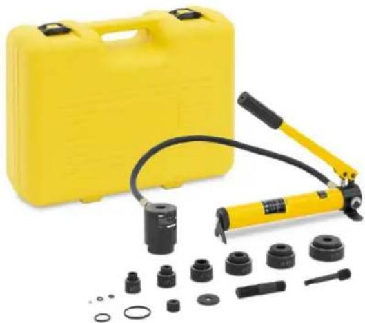
| General information | Manual hydraulic tool for punching holes in sheets. Delivered with pump and cylinder. |
Frequently Asked Questions - HPM-01 MSW
User questions about HPM-01 MSW
0 question about this device. Answer the ones you know or ask your own.
Ask a new question about this device
Download the instructions for your Drill in PDF format for free! Find your manual HPM-01 - MSW and take your electronic device back in hand. On this page are published all the documents necessary for the use of your device. HPM-01 by MSW.
USER MANUAL HPM-01 MSW
HYDRAULIC HOLE DIGGER
| DE | Produktname | Hydraulischer Lochbagger |
| EN | Product name | Hydraulic hole digger |
| PL | Nazwa produktu | Hydrauliczna koparka do otworów |
| CZ | Název výrobku | Hydraulický bagr |
| FR | Nom du produit | Tarière hydraulique |
| IT | Nome del prodotto | Scavatrice idraulica per buche |
| ES | Nombre del producto | Excavadora de agujeros hidráulica |
| HU | Termék neve | Hidraulikus lyukásó |
| DA | Produktnavn | Hydraulisk hulgraver |
| FI | Tuotteen nimi | Hydraulinen kaivuri |
| NL | Productnaam | Hydraulische gatgraver |
| NO | Produktnavn | Hydraulisk hullgraver |
| SE | Produktnamn | Hydraulisk hålgrävare |
| PT | Nome do produto | Escavadeira hidráulica |
| SK | Názov produktu | Hydraulický vykopávač otvorov |
| BG | Име на продукта | Хидравличен дупкокоп |
| EL | Όνομα προϊόντος | Υδραυλικό τρυπάνι |
| HR | Naziv proizvoda | Hidraulički kopač rupa |
| LT | Produkto pavadinimas | Hidraulinis skylių kastuvas |
| RO | Numele produsului | Sapat hidraulic pentru gauri |
| SL | Ime izdelka | Hidravlični kopač lukenj |
| DE Modell | EN Product model | PL Model produktu | CZ Model výrobku | FR Modèle | IT Modello | ES Modelo | HU Modell | DA Model | FI Tuotteen malli | NL Productmodel | NO Produktmodell | SE Produktmodell | PT Modelo do produto | SK Model | BG Модел на продукт | EL Movtėlo προϊόντος | HR Model proizvoda | LT: Gaminio modelis | RO: Model de produs | SL: Model izdelka | MSW-HPM-01 | |
| DE Hersteller | EN Manufacturer | PL Producent | CZ Výrobce | FR Fabricant | IT Produttore | ES Fabricante | HU Termelő | DA Producent | FI Valmistaja | NL Producent | NO Produsent | SE Tillverkare | PT Fabricante | SK Výrobca | BG Производител | EL Κατασκευαστής | HR Proizvođač | LT Gamintojas | RO Producător | SL Proizvajalec | expondo Polska sp. z o.o. sp. k. | |
| DE Anschrift des Herstellers | EN Manufacturer Address | PL Adres producenta | CZ Adresa výrobce | FR Adresse du fabricant | IT Indirizzo del produttore | ES Dirección del fabricante | HU A gyártó címe | DA Producentens adresse | FI Valmistajan osoite | NL Adres producent | NO Produsentens adresse | SE Tillverkarens adress | PT Endereço do fabricante | SK Adresa výrobcu | BG Адрес на производителя | EL: Διεύθυνση κατασκευαστή | HR Adresa proizvođača | LT Gamintojo adresas | RO Adresa producătorului | SL Naslov proizvajalca | ul. Nowy Kisielin – Innowacyjna 7, 66-002 Zielona Góra | Poland, EU | |

natural_image
Yellow portable hydraulic cylinder and mechanical components (no text or symbols visible)natural_image
3D rendered image of a mechanical tool with a blue handle and coiled spring, labeled with number 8 (no text or symbols on the object itself)IV
This User Manual has been translated using machine translation. We have made every effort to ensure the translation is accurate, but please note that automated translations are not perfect and are not meant to replace human translators. The official version of the User Manual is in English. Any differences between the translated version and the original English are not legally binding. If you have any questions about the accuracy of the translation, please refer to the English version, which is the official reference. More language versions are available upon request via info@expondo.com.
Technical data
| Parameter description | Parameter value |
| Product name | Hydraulic hole digger |
| Model | MSW-HPM-01 |
| Capacity max output [ton] | 8 |
| Punching range in diameter [mm] | 22-60 |
| Dimensions (Width x Length x Height) [mm] | 170x405x170 |
| Weight [kg] | 5.3 |
Purpose
natural_image
Yellow portable hydraulic cylinder and mechanical components (no text or symbols visible)The product is a tool used for for making holes on metal sheet with thickness below 3mm.
The user is liable for any damage resulting from unintended use of the product.
Operating instructions

WARNING
No-load pressing without installing die is prohibited.
Procedures in general
-
Preparation: Begin by drilling an 11.5mm guide hole in the workpiece using a hand electric drill.
-
Assembly: Insert the pulling rod of the piston into the screw thread of the piston cylinder. Attach the washer to the pulling rod and place it into the cavity die. Stretch the piston pulling rod into the guide
hole and secure the cavity die by twisting it, ensuring the blade of the cavity die tightly contacts the surface to be processed. At this point, the convex die, workpiece, and cavity die are firmly fixed.
-
Operation: Close the spill valve by turning it clockwise. Then, repeatedly press the step-up handle to activate the plunger pump, which increases the oil pressure. This generates a shearing force between the convex and cavity dies, cutting through the workpiece.
-
Unloading: Once the hole is completed, loosen the spill valve by turning it anti-clockwise to release the oil pressure.
-
Cleanup: Remove the convex die, clear any waste material from the cavity die, and wipe the mold clean.
Setup and Operation
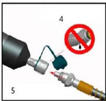
- Remove the dust caps from the couplers; attach the hose to the ram and to the pump. Thread the dust caps together.

NOTE Hand-tighten the couplers completely until all threads are engaged. Do not use tools.
-
Select the punch, die, and draw stud that will make the appropriate size hole.
-
Determine and mark the exact location for the hole. Using a drill bit that is slightly larger than the draw stud, drill a hole. This is the pilot hole.

NOTE For a punch and die with a 3/8" center hole, thread the 3/8" adapter draw stud into the end of the piston shaft. For a punch and die with a 1-1/8" center hole, thread the screw sleeve onto the piston shaft.
-
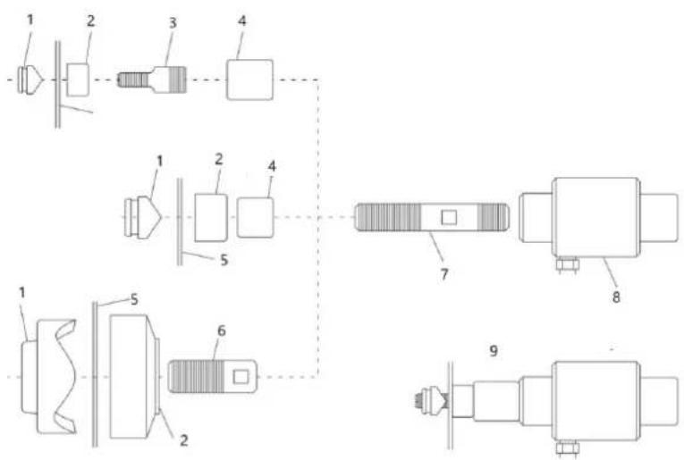
Thread the 3/4" piston shaft completely into the ram. Refer to the illustration.
-
Install spacers as necessary. Refer to the illustrations on this page.
-
Slide the die over the draw stud with the open end of the die facing away from the ram.
-
Insert the draw stud through the pilot hole.
-
Punch
-
Die
-
3/8" Adapter Draw Stud
-
Spacer
-
Material
-
1-1/8" Sleeve
-
3/4" Draw Stud
-
Ram
-
Completed Assembly
-
Thread the punch onto the draw stud with the cutting surfaces of the punch facing the material. Tighten the punch by hand until the spacers, die, material, and punch are snug.

NOTE All of the punch threads must be engaged by the draw stud threads. If any of the punch threads are not engaged, disassemble the setup, remove one of the spacers, and reassemble the setup.

WARNING
Do not operate the pump after ram motion stops. Continuing to operate the pump lever after the ram stops will damage the ram.
If the ram stops before the hole is complete, stop pumping. Check that the setup is correct and that you have not exceeded the tool's capacity. Refer to the setup instructions. If necessary, disassemble the setup and add a spacer.
-
Activate the pump. For specific instructions, refer to the operating manual supplied with the pump. Support the weight of the ram when operating the pump. This will prevent the ram from falling when the punch is complete.
-
Release the pressure at the pump.
Illustration for reference

CAUTION
• Do not knock any part of the tool, as this could be dangerous for the operator.
• Do not hold the hose when it is under pressure.

WARNING
- The coupler can connect the pump with other tool quickly and easily. The male and female coupler must connect well, otherwise it may cause hurt to operator.
- Pumping the handle gently to make the oil flows smoothly, otherwise it will damage the hydraulic system.
1
III
natural_image
3D rendered image of a mechanical tool with a blue cylindrical body and attached spring, labeled with number 8 (no text or symbols on the object itself)IV
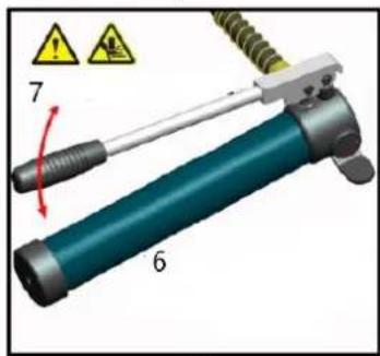
- Active handle
-
Oil reservoir
-
Release pressure manually
-
Take relevant item
-
Connect the coupler to the split working head
-
Before operating, spin the turn screw tightly in clockwise
-
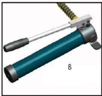
Pumping the handle
-
After completing one cycle, loosen the turn screw to release the pressure.
Adding hydraulic oil
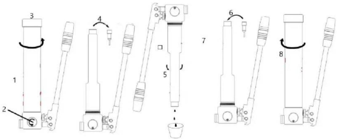
-
Fixed onto bench vice in vertical
-
Rotate turn screw to release pressure
-
Spin pump handle out
-
Take out plug
-
Draining out waste oil
-
Filling clean hydraulic oil
-
Exhaust air and insert oil plug
-
Spin pump handle back
Maintenance

WARNING Damaged equipment can cause serious personal injury. Do not use damaged equipment. If you notice abnormal noise or vibration, have the issue corrected before using the equipment further.

NOTE Dust or air inside the tool can damage the sealing kit, causing the tool to lose functionality. When changing the oil, ensure the oil is clean and free of dust. Allow some time for the oil to fully drain from the tube before inserting the oil plug.
-
Before each using, inspect the general condition of the tool. Check for the coupler is clean. Check for loose screws, misalignment or binding of moving parts, cracked or broken parts, or any other condition that may affect its safe operation.
-
After using, clean external surfaces of the tool with clean, moist, smear the rust preventing oil on the metal surface of the tool and the dies to avoid rusty. Store the tool in the dry environment. The coupler should be covered by the cap in timely, otherwise the dust will enter into and pollute the oil.
-
Service to the tool should only be done by a qualified Service Technician.
-
In order to prolong the life of the tool please change the oil per year. Make sure the oil filtered by 120 mesh net or over 30μm strainer. Meantime avoid the dusty into the oil cup.
-
After a long time using, the sealing kits will be damaged, if there is leakage please contact with the manufacturer and/or the distributor to change the sealing kits.
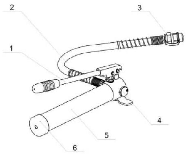
Parts (for reference)

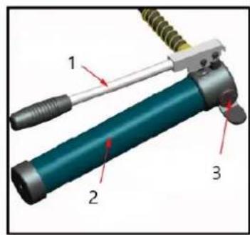
| No. | Name | Function |
| 1 | active handle | for operation |
| 2 | hose | for transporting oil |
| 3 | coupler | for connecting with working head |
| 4 | Turn screw | for releasing pressure |
| 5 | Pump body | for storing oil |
| 6 | Screw cap | for covering the oil tube to prevent oil from leaking |

natural_image
Yellow portable hydraulic cylinder and mechanical components (no text or symbols visible)natural_image
3D rendered image of a mechanical tool with a blue cylindrical body and attached lever, labeled with number 8 (no text or symbols on the object itself)IV
natural_image
Yellow portable hydraulic cylinder and mechanical components (no text or symbols visible)natural_image
3D rendered image of a mechanical tool with a blue cylindrical body and attached spring, labeled with number 8 (no text or symbols on the object itself)IV
natural_image
Yellow portable hydraulic cylinder and mechanical components (no text or symbols visible)natural_image
3D rendered image of a mechanical tool with a blue cylindrical body and attached spring, labeled with number 8 (no text or symbols on the object itself)IV
natural_image
Yellow portable hydraulic cylinder and mechanical tools including a pressure relief valve and multiple pressure fittings (no text or symbols visible)natural_image
3D rendered image of a mechanical tool with a blue cylindrical body and attached spring, labeled with the number 8 (no text or symbols on the object itself)IV
natural_image
Yellow portable hydraulic cylinder and mechanical components (no text or symbols visible)natural_image
3D rendered image of a mechanical tool with a blue cylindrical body and attached spring, labeled with the number 8 (no text or symbols on the object itself)IV
natural_image
Yellow portable hydraulic cylinder and mechanical components (no text or symbols visible)natural_image
3D rendered image of a mechanical tool with a blue cylindrical body and attached spring, labeled with the number 8 (no text or symbols on the object itself)IV
natural_image
Yellow hard-shell mechanical device with hydraulic cylinder and multiple cylindrical components (no text or symbols visible)natural_image
3D rendered image of a mechanical tool with a blue cylindrical body and attached spring, labeled with number 8 (no text or symbols on the object itself)IV
Dele (til reference)

natural_image
Yellow portable hydraulic cylinder and mechanical components (no text or symbols visible)natural_image
Close-up of a blue cylindrical mechanical device with attached spring and lever (no visible text or symbols)IV
natural_image
Yellow portable hydraulic cylinder and mechanical components (no text or symbols visible)natural_image
3D rendered image of a mechanical tool with a teal cylindrical body and attached spring, labeled with the number 8 (no text or symbols on the object itself)IV
natural_image
Yellow hard-shell mechanical device with hydraulic cylinder and multiple cylindrical components (no text or symbols visible)-
Punch
-
D∅
-
3/8" Adapter Draw Stud
-
Avstandsstykke
-
Materiale
-
1-1/8" erme
-
3/4" Draw Stud
-
Vær
-
Fullført montering
-
Tre stansen på trekkbolten med skjæreflatene på stansen vendt mot materialet. Stram stempelet for hånd til avstandsstykkene, stansen, materialet og stempelet sitter tett.

natural_image
3D rendered image of a mechanical tool with a blue cylindrical body and attached spring, labeled with number 8 (no text or symbols on the object itself)IV
Deler (for referanse)
natural_image
Yellow portable hydraulic cylinder and mechanical components (no text or symbols visible)natural_image
3D rendered image of a mechanical tool with a blue cylindrical body and attached spring, labeled with number 8 (no text or symbols on the object itself)IV
natural_image
Yellow portable hydraulic cylinder and mechanical components (no text or symbols visible)natural_image
3D rendered image of a mechanical tool with a blue cylindrical body and attached spring, labeled with the number 8 (no text or symbols on the object itself)IV
natural_image
Yellow portable hydraulic cylinder and mechanical components (no text or symbols visible)natural_image
3D rendered image of a mechanical tool with a blue cylindrical body and attached spring, labeled with the number 8 (no text or symbols on the object itself)IV
natural_image
Yellow portable hydraulic cylinder and mechanical components (no text or symbols visible)natural_image
3D rendered image of a mechanical tool with a blue cylindrical body and attached lever, labeled with number 8 (no text or symbols on the object itself)IV
natural_image
Yellow portable hydraulic cylinder and mechanical components (no text or symbols visible)natural_image
3D rendered image of a mechanical tool with a blue cylindrical body and attached spring, labeled with the number 8 (no text or symbols on the object itself)IV
natural_image
Yellow hard-fit medical or hydraulic tool kit with various mechanical components and a cylindrical device (no visible text or labels)Proizvod je alat koji se koristi za izradu rupa na metalnom limu debljine ispod 3 mm.
-
Bušiti
-
Umrijeti
-
3/8" adapter za izvlačenje
-
Razmaknica
-
Materijal
-
1-1/8" rukav
-
3/4" zatezni klin
-
Ovan
-
Završena montaža
-
Navucite bušilicu na zatezni klin tako da rezne površine bušilice budu okrenute prema materijalu. Zategnite proboj rukom dok razmaknice, matrica, materijal i proboj ne nalegnu.

BILJEŠKA Svi navoji za bušenje moraju biti zahvaćeni navojima za izvlačenje. Ako bilo koji od navoja za bušenje nije zahvaćen, rastavite sklop, uklonite jedan od odstojnika i ponovno sastavite sklop.

UPOZORENJE
natural_image
Mechanical tool with a blue cylindrical body and attached spring, labeled with number 8 (no text or symbols on the tool itself)IV
-
Okomito fiksiran na stegu za stol
-
Okrenite zakretni vijak kako biste oslobodili pritisak
-
Ručka pumpe centrifuge prema van
-
Izvadite utikač
-
Ispuštanje otpadnog ulja
-
Punjenje čistog hidrauličkog ulja
-
Ispustite zrak i umetnite čep za ulje
-
Spin pumpa ručka natrag
Održavanje

UPOZORENJE Oštećena oprema može uzrokovati ozbiljne ozljede. Nemojte koristiti oštećenu opremu. Ako primijetite neuobičajenu buku ili vibracije, otklonite problem prije daljnje upotrebe opreme.

BILJEŠKA Prašina ili zrak unutar alata mogu oštetiti komplet za brtvljenje, uzrokujući gubitak funkcionalnosti alata. Kada mijenjate ulje, provjerite je li ulje čisto i bez prašine. Ostavite neko vrijeme da ulje u potpunosti iscuri iz cijevi prije umetanja čepa za ulje.
natural_image
Yellow portable hydraulic cylinder and mechanical components (no text or symbols visible)natural_image
3D rendered image of a mechanical tool with a blue cylindrical body and attached spring, labeled with number 8 (no text or symbols on the object itself)IV
natural_image
Yellow portable hydraulic cylinder and mechanical components (no text or symbols visible)natural_image
3D rendered image of a mechanical tool with a blue cylindrical body and attached spring, labeled with the number 8 (no text or symbols on the object itself)IV
natural_image
Yellow portable hydraulic cylinder and mechanical components (no text or symbols visible)-
udarec
-
Umri
-
3/8" adapter za zategovanje
-
Distančnik
-
Material
-
1-1/8" rokav
-
3/4" zatezni žebljiček
-
Ram
-
Končana montaža
-
Navijte luknjač na vlečni čep tako, da so rezalne površine luknjača obrnjene proti materialu. Ročno zategnite luknjač, dokler se distančniki, matrica, material in luknjač ne prilegajo.

natural_image
Mechanical tool with a blue cylindrical body and attached spring, labeled with number 8 (no text or symbols on the tool itself)IV
For the disposal of the device please consider and act according to the national and local rules and regulations.
CONTACT
expondo Polska sp. z o.o. sp. k.