TBBD-1500AT - Drill MSW - Free user manual and instructions
Find the device manual for free TBBD-1500AT MSW in PDF.

| Product type | Pillar drill |
| Brand | MSW |
| Model | TBBD-1500AT |
| Rated voltage | 230 V ~ 50 Hz |
| Rated power | 550 W |
| No-load speed | 510-2430 rpm |
| Spindle-to-column distance | 250 mm |
| Spindle stroke | 50 mm |
| Dimensions (L x W x H) | 490 x 300 x 740 mm |
| Weight | 21 kg |
| Drillable materials | Metal, plastic, wood and similar materials |
| Main functions | Drilling |
| Power supply | Mains |
| Recommended electrical protection | Residual current device (RCD) |
| Included safety equipment | Chuck guard, belt guard, emergency stop switch |
| Recommended personal protective equipment | Safety goggles, dust mask, earplugs, gloves, safety shoes |
| Maintenance | Regular cleaning, lubrication of moving parts, check of bolts and screws |
| Available spare parts | Carbon brushes, drive belt |
| Repairability | Contact an authorized service center for repairs |
| General information | Manual available in multiple languages. Product recyclable. |
Frequently Asked Questions - TBBD-1500AT MSW
User questions about TBBD-1500AT MSW
0 question about this device. Answer the ones you know or ask your own.
Ask a new question about this device
Download the instructions for your Drill in PDF format for free! Find your manual TBBD-1500AT - MSW and take your electronic device back in hand. On this page are published all the documents necessary for the use of your device. TBBD-1500AT by MSW.
USER MANUAL TBBD-1500AT MSW
natural_image
Close-up of a mechanical component with a hexagonal bolt and circular head (no visible text or symbols)


natural_image
Close-up of a drill bit on a wooden surface with labeled components (no text or symbols beyond labels)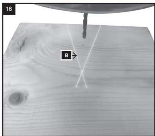
natural_image
Mechanical assembly diagram showing a tool inserted into a component, with no visible text or symbolsnatural_image
Technical line drawing of a mechanical device with arrows indicating assembly or force direction (no text or symbols)natural_image
Mechanical lever mechanism diagram showing pivot and pivot components (no text or labels)natural_image
Diagram of a mechanical press or drill bit pressing down on a wooden surface, with arrows indicating force direction (no text or symbols present)natural_image
Illustration of a drill bit with a tool and directional arrow indicating rotation (no text or symbols)natural_image
Technical illustration of a drill press machine with a drill bit and handle (no text or symbols)natural_image
Mechanical assembly diagram showing a rotating component with a circular head and curved shaft (no text or symbols)natural_image
Mechanical assembly diagram showing a lever mechanism with no visible text or symbolsnatural_image
Diagram of a mechanical assembly with a rotating component and directional arrows indicating motion (no text or symbols)natural_image
Diagram of a mechanical tool with a rotating shaft and handle, showing motion direction (no text or symbols)
natural_image
Diagram of a drill bit with a tool and arrow indicating rotation (no text or symbols)natural_image
Line drawing of a mechanical drill press with a central spindle and base platform (no text or symbols)natural_image
Diagram of a sewing machine with a drill bit and mechanical components, showing no text or symbols.natural_image
Diagram of an electrical switch panel with a valve and tubing, no text or symbols presentnatural_image
Technical line drawing of a mechanical component with concentric grooves and a base (no text or symbols)This User Manual has been translated for your convenience using machine translation. Reasonable efforts have been made to provide an accurate translation; however, no automated translation is perfect nor is it intended to replace human translators. The official User Manual is the English version. Any discrepancies or differences created in the translation are not binding and have no legal effect for compliance or enforcement purposes. If any questions arise related to the accuracy of the information contained in the User Manual, please refer to the English version of those contents which is the official version.
Technical data
| Parameter description Parameter value | |
| Product name | Bench Top Drill Press |
| Model | MSW-TBBD-1500AT |
| Rated voltage [V~] / frequency [Hz] | 230/50 |
| Rated power [W] | 550 |
| No Load Speed [rpm] | 510-2430 |
| Distance between spindle and column [mm] | 250 |
| Spindle travel [mm] | 50 |
| Dimensions [width x depth x height; mm] | 490 x 300 x 740 |
| Weight [kg] | 21 |
1. General description
The user manual is designed to assist in the safe and trouble-free use of the device. The product is designed and manufactured in accordance with strict technical guidelines, using state-of-the-art technologies and components. Additionally, it is produced in compliance with the most stringent quality standards.
DO NOT USE THE DEVICE UNLESS YOU HAVE THOROUGHLY READ AND UNDERSTOOD THIS USER MANUAL.
To increase the product life of the device and to ensure trouble-free operation, use it in accordance with this user manual and regularly perform maintenance tasks. The technical data and specifications in this user manual are up to date. The manufacturer reserves the right to make changes associated with quality improvement. The device is designed to reduce noise emission risks to a minimum, taking into account technological progress and noise reduction opportunities.
Legend


The product satisfies the relevant safety standards.
Read instructions before use.
The product must be recycled.
WARNING! or CAUTION! or REMEMBER! Applicable to the given situation. (general warning sign)
Use ear protection. Exposure to loud noise may result in hearing loss.
Wear protective goggles.
Wear a dust mask (respiratory tract protection).
Wear protective gloves.
Wear foot protection.
NOTE: Laser beam. It is forbidden to look at the laser light.

PLEASE NOTE! Drawings in this manual are for illustration purposes only and in some details may differ from the actual product.
2. Usage safety

ATTENTION! Read all safety warnings and all instructions. Failure to follow the warnings and instructions may result in electric shock, fire and/or serious injury or even death.
The terms "device" or "product" are used in the warnings and instructions to refer to:
Bench Top Drill Press
I. SAFETY INSTRUCTIONS
a) Keep the work area clean. Cluttered areas can cause injuries.
b) Consider the work area environment before starting to work. Don't expose power tools to rain or wet soil. Don't use power tools in damp or wet locations. The work area should be well secured. Don't use the tool in the presence of flammable liquids or gases. Power tools produce sparks during normal operation or when switching ON/OFF. Never use power tools in dangerous sites containing lacquer, paint, benzene, thinner, gasoline, gases, adhesive agents, and other materials which are combustible or explosive.
c) Provide sufficient protection against electric shock. Prevent body contact with grounded surfaces. For example: pipes, radiators, ranges, refrigerator enclosures.
d) Keep children and third parties away from the work area.
e) Store unused tools. When not in use, tools should be stored in dry and high or locked-up place out of the reach of children.
f) Do not overload the machine! To ensure an optimum performance and safety of the machine, only use it within the set parameters.
g) Use only suitable tools. Don't use small tools or attachments. Don't use tools for not intended purposes. For example: don't use circular saws for cutting tree limbs or logs.
h) Dress appropriately. Do not wear loose clothing or jewellery. They can get caught in the moving parts. Rubber gloves and non-skid footwear are recommended when working outdoors. Wear protective hair covering to contain long hair.
i) Use safety glasses. Also use face or dust mask if the cutting operation is dusty.
j) Do not damage the connection cable. Never carry the tool by the cord or yank the cord to disconnect it from the power source. Keep the cord away from heat and oil sources and sharp edges.
k) Secure the work area. It is recommended to use clamps or a vice for fixation. Please pay special attention to your hands when operating the machine.
I) Do not overreach yourself. Keep proper footing and balance at all times.
m) Hold the machine firmly with both hands. When using the machine, hold it by the handles provided with the machine.
n) Maintain tools with care. Keep tools clean for a better and safer performance. Follow the instructions for changing accessories. Inspect the extension cords periodically and replace if damaged. Keep handles dry, clean, and free from oil and grease.
o) Switch off the machine and disconnect the cable before performing maintenance or changing accessories.
p) Remove adjusting keys and wrenches. Always make sure that keys and adjusting wrenches are removed from the tool before turning it on.
q) Avoid unintentional starting. Don't carry a plugged-in tool with your fingers on the switch. Be sure the tool is switched off when plugging it in.
r) Stay alert when operating the machine. Do not operate the tool when you are tired.
s) Check damaged parts. Before further use of the tool, any part of the casing or other parts that are damaged should be carefully checked to determine if they will operate properly and perform their intended function. Check for alignment of moving parts, mounting, and any other conditions that may affect its operation. A damaged part should be properly repaired or replaced by an authorized service centre unless otherwise indicated elsewhere in this instruction manual. Defective switches should be replaced by an authorized service centre. Do not use the tool if the switch does not turn it on and off.
t) Do not use power tools for applications other than those specified in the instructions (other than that for which it was designed).
u) To ensure the designed operational integrity of power tools, do not remove installed covers or screws.
v) Do not touch movable parts or accessories unless the power source has been disconnected.
w) Use your tool at a lower input load than specified on the nameplate to increase working efficiency and decrease the wearing out process.
x) Do not wipe any plastic parts with solvents. Solvents such as gasoline, thinner, benzene, alcohol, ammonia and oil may damage and crack the plastic parts. Do not wipe them with such solvents. Wipe the plastic parts with a soft cloth lightly dampened with soapy water.
y) Consult an authorized service agent in the event of power tool failure.
z) Use only original replacement parts.
aa) This tool should only be disassembled for replacement of carbon brushes.
bb) For transporting and moving drills from storage to the place of use, it is necessary to take into account the health and safety rules during manual transport works that are in force in the country where the demolition hammers are used.
cc) It is not allowed to climb onto the machine.
II. PRECAUTIONS ON USING THE MACHINE
a) Wear protective glasses to protect your eyes.
b) Use dust masks.
c) Use earplugs to keep your ears noise-free while working.
d) Check for the proper handle adjustment.
e) The tool becomes very hot during operation.
f) Safe operation depends on one's work posture.
g) When working in an elevated location, pay attention to objects and persons below.
h) Wear protective shoes to protect your feet.
Failure to follow safety recommendations and instructions may result in serious injuries or death!

ATTENTION! Despite the safe design of the device and its protective features, and despite the use of additional elements protecting the operator, there is still a slight risk of accident or injury when using the device. Stay alert and use common sense when using the device.
3. Use guidelines
The tabletop drill is intended to drill metal, plastic, wood and similar materials.
The product is intended for home use only.
The user is liable for any damage resulting from unintended use of the device.
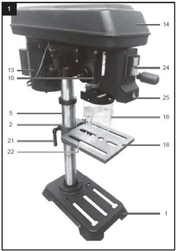
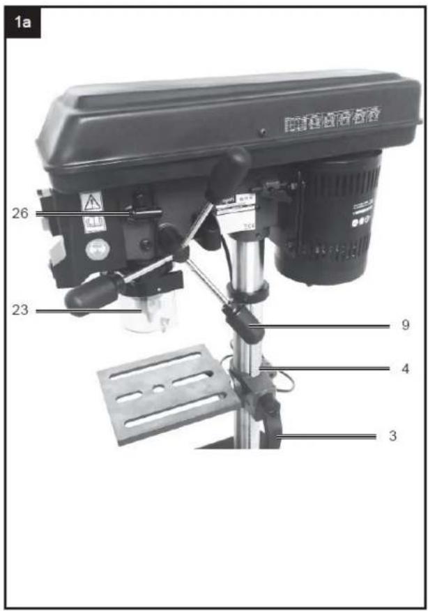
3.1. Device description


natural_image
Close-up of a mechanical component with a hexagonal bolt and circular head (no visible text or symbols)


EN


natural_image
Close-up of a drill bit on a wooden surface with labeled components (no text or symbols beyond labels)


natural_image
Technical line drawing of a mechanical clamp or clamping device with a vertical rod and rectangular base (no text or symbols)-
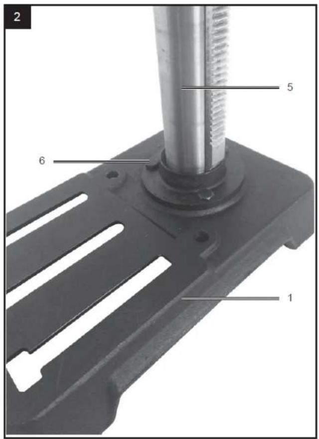
Base plate
-
Drilling table holder
-
Height adjustment lever
-
Toothed rack column
-
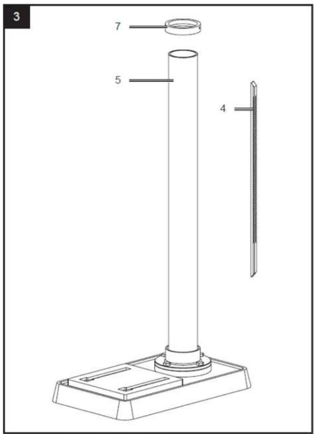
Column
-
Screw
-
Ring
-
Machine head
-
Handle
-
Depth stop
-
knurled nut
-
Stop
-
Engine
-
Belt guard
-
Locking screw
-
Chuck guard
-
Slotted screw
-
Drilling table
-
Angle scale
-
Screw 90° attachment
-
Clamping handle for height adjustment
-
Clamping screw for drilling table
-
Sprocket chuck
-
On/Off Switch
-
Laser On/Off switch
-
Chuck key
-
Spring cap
-
Groove
-
Outer nut
-
Inner nut
-
Notch
-
Hub
-
Spindle
-
Lock nut
-
Screw
-
Drive belt
-
Wing screw
-
Pulleys
3.2. Assembling the device

WARNING: DURING ASSEMBLY ENSURE THE A DRILL PRESS IS DISCONNECTED FROM THE POWER SUPPLY.
Assembling the drill press
- Carefully remove contents from the packaging.
- Select a firm, level surface on which to assemble the drill press.
- Place the base and align the column over the large hole. Align the holes in the column support with those in the base and secure in place using the 3 column support bolts (supplied). Using a 14mm spanner securely tighten all 3 column support bolts.
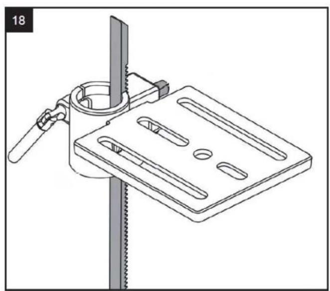
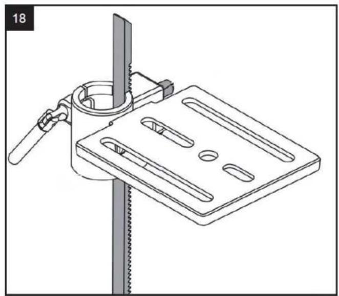
- Slide the table support over the column. Using the table support lock, secure the table into the desired position.
natural_image
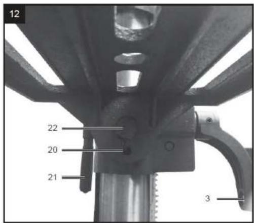
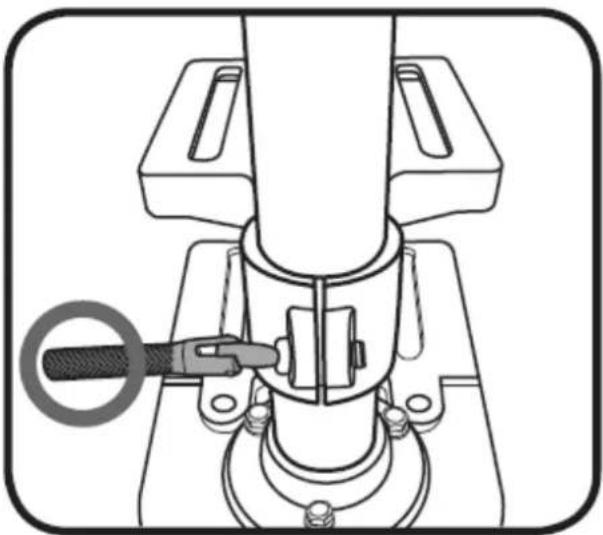
Mechanical assembly diagram showing a tool inserted into a component, with no visible text or symbols- Lift the head assembly and slide it down onto the column as far as it will go. Rotate the head so that is aligned with the base.
To secure in position install the 2 head lock screws. Tighten using the 4mm Hex key, rotating in a clockwise direction.
natural_image
Technical line drawing of a mechanical device with arrows indicating assembly or force direction (no text or symbols)-
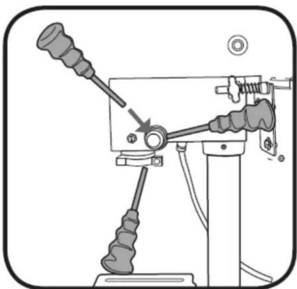
To fit the eye shield, first loosen the Phillips head screw on the shield and then slide over the drill spindle. Tighten the securing screw to lock in position.
-
To fit the feed wheel handles, screw them into the feed wheel hub.
natural_image
Mechanical lever mechanism diagram showing pivot and pivot components (no text or labels)- To fit the keyed chuck, first place a piece of timber on the table and position the keyed chuck with the jaws retracted under the drive shaft. Raise the table toward the drive shaft until the chuck is approximately 25mm from the drive shaft.
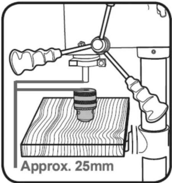
- To secure the keyed chuck to the drive shaft gently lower the drive shaft using the feed wheel handles until the drive shaft is pushed into the rear of the keyed chuck. A gentle tap on the timber is required to secure the keyed chuck onto the tapered drive shaft.
natural_image
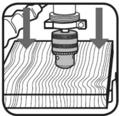
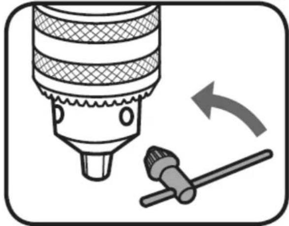
Diagram of a mechanical press or drill bit pressing down on a wooden surface, with arrows indicating force direction (no text or symbols present)Installing and removing drill bits
- Using the chuck key, loosen the jaws of the chuck by rotating in an anti-clockwise direction.
natural_image
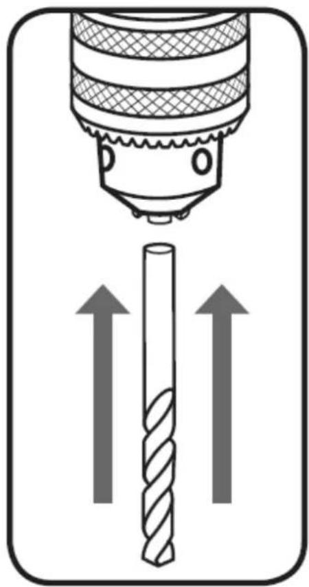
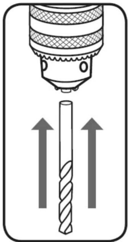
Illustration of a drill bit with a tool and directional arrow indicating rotation (no text or symbols)- Insert the drill bit fully into the keyed chuck.
natural_image
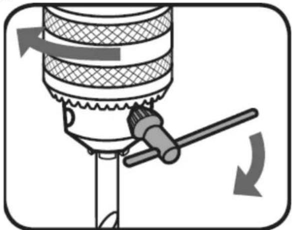
Diagram of a drill bit with directional arrows indicating compression or movement (no text or symbols)- Whilst holding the drill bit in one hand, rotate the top collar of the keyed chuck in a clockwise direction.
Ensure that you tighten all 3 holes in the keyed chuck using the chuck key to securely tighten the jaws and hold the drill bit in position.
natural_image
Diagram of a mechanical device with a lever and rotating arrow, no text or symbols presentHeight and angle adjustments

WARNING: BEFORE MAKING ANY ADJUSTMENTS, A ENSURE THE DRILL PRESS IS DISCONNECTED
FROM THE MAINS POWER
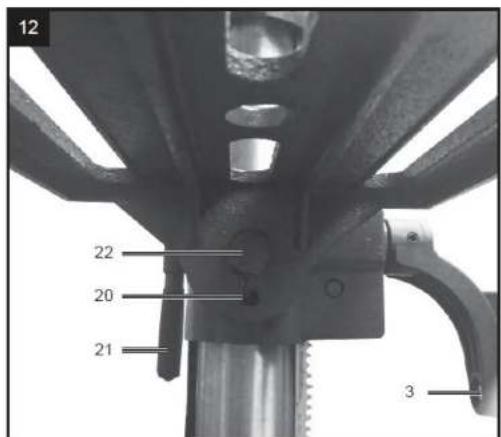
Adjusting the table height
- Loosen the table support lock
- Set the desired table height and tighten the table support lock to secure the table in position.
natural_image
Technical line drawing of a mechanical clamp or fixture assembly (no text or symbols)
natural_image
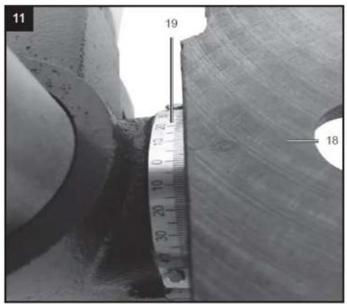
Diagram of a mechanical press or drill machine with a vertical dimension arrow indicating measurement (no text or symbols present)Adjusting the table angle
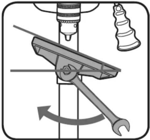
The table can be adjusted up to 45^ to the left or right.
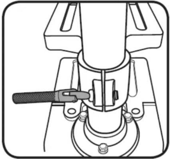
- Loosen the table support angle bolt (located below the table) by rotating anti-clockwise using a 19mm spanner or shifter (not supplied).
- Align and set the desired angle. Tighten the table support angle bolt by rotating in a clockwise direction to secure the table in position.
natural_image
Mechanical assembly diagram showing a tool interacting with a bracket and wrench, with no visible text or symbols.
WARNING: WHEN THE TABLE IS ANGLED/TILTED, ENSURE THE WORKPIECE IS CLAMPED TO THE
TABLE
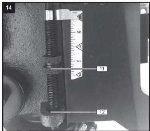
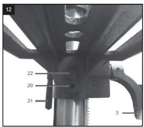
Pre-setting the drilling depth
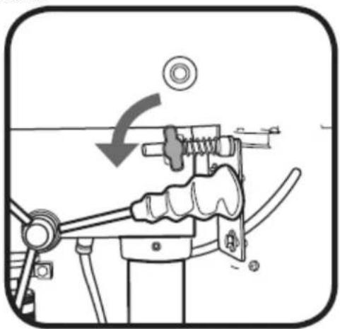
- Loosen the depth adjustment lock nut by turning in an anti-clockwise direction.
- Rotate the depth adjustment ring until the desired drilling depth aligns with the point indicator. Tighten the depth adjustment lock nut to secure this position.
- Ensure the drill bit is secured in the chuck and then proceed to operate the drill press. Once the drill lowers to the selected depth, the stop will engage to prevent drilling any lower.
natural_image
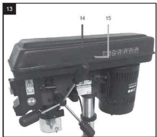
Technical illustration of a drill press machine with a downward arrow indicating force or direction (no text or symbols present)Changing the speed
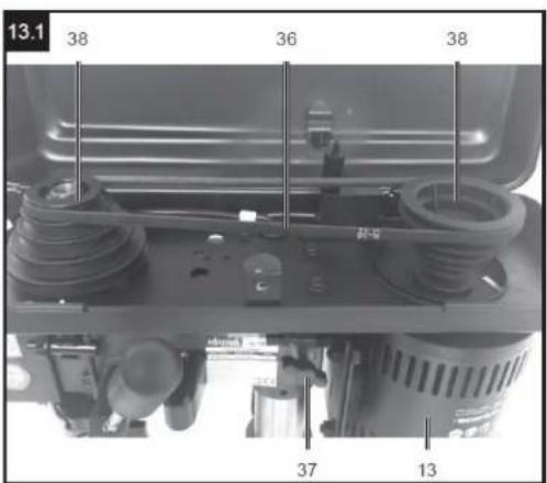
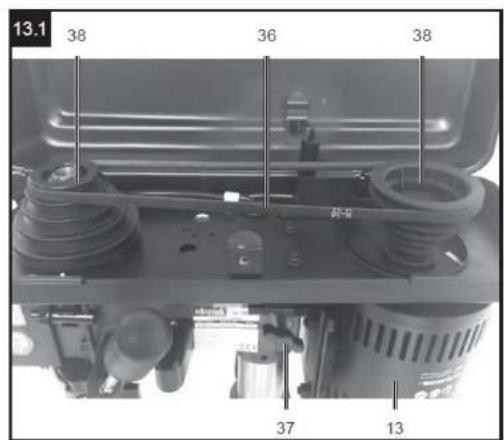
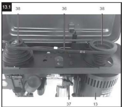
The speed of the drill press can be changed by adjusting the belts on the pulley system.
Using a smaller pulley on the spindle side increases the drill speed. Using a larger pulley on the motor side will also increase the drill speed.
| 510 min ^-1 | 800 min ^-1 | 1300 min ^-1 | 1800 min ^-1 | 2430 min ^-1 |
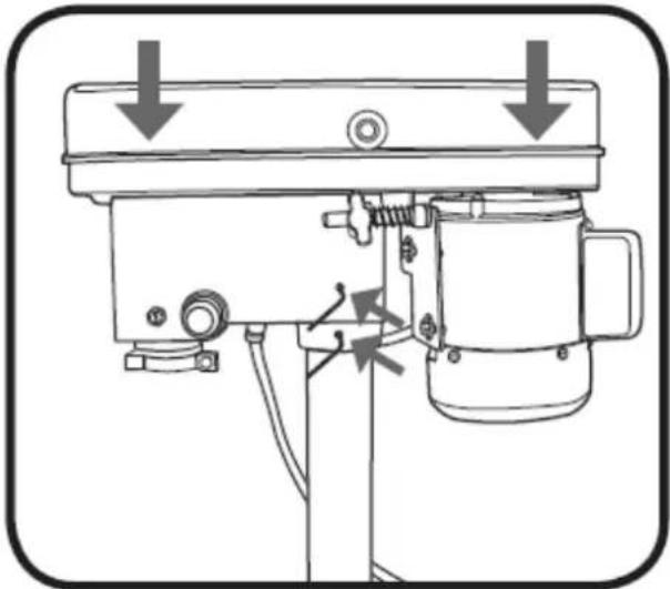
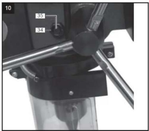
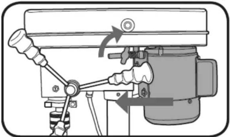
- Loosen the 2 belt tension knobs.
natural_image
Mechanical assembly diagram showing a lever mechanism with a rotating head and gear (no text or symbols)-
Push the motor towards the head assembly and tighten the belt tension knobs.
-
To adjust the belt speed, move the belts to the correct pulley step for the speed required. See the diagram above for all belt configurations. When moving the belt, it is easier to place the belt onto the small pulley first and then turn it onto the larger pulley.
-
To apply tension to the belt once it has been fitted to a new speed setting, loosen the belt tension knobs. Pull the motor away from the head assembly and then re-tighten the belt tension knob.
-
Ensure the pulley cover is closed and secured with the pulley cover screw.
3.3. Device use
Turning On and Off
WARNING: THE POWER SUPPLY FOR THIS PRODUCT SHOULD BE PROTECTED BY A RESIDUAL CURRENT DEVICE. A RESIDUAL CURRENT DEVICE REDUCES THE RISK OF ELECTRIC SHOCK.
Note: The pulley cover is fitted with a safety switch and must be closed to operate the drill press.
- Switch the drill press on by pressing the green (I) button on the switch.
- Switch the drill press off by pressing the red (0) button on the switch.
- Secure your workpiece to the table if possible, use a vice or clamps (not supplied).
An emergency off switch is located at the front of the drill press to allow quick access to stop the unit off. Simply press this button in, to switch the unit off. This button must then be released by rotating it anticlockwise before the drill can be started again.
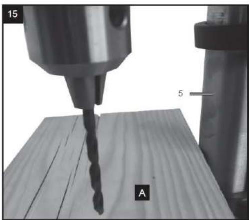
Operating the drill press
- Ensure the drill press is switched off and disconnected from the power supply.
- Loosen the jaws of the keyed chuck with the chuck key by turning in an anti-clockwise direction and insert the selected drill bit into the chuck as far as it will go.
-
Ensure that the drill bit is centred in the chuck and tighten the chuck jaws with the chuck key in a clockwise direction. Tighten all three holes to ensure the drill bit is secured evenly by each jaw.
-
Select your drilling depth and secure the depth adjustment lock nut in position
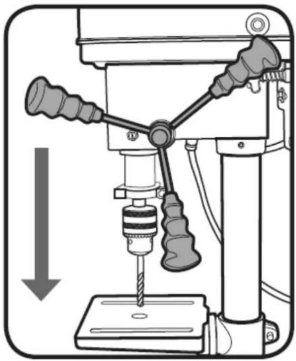
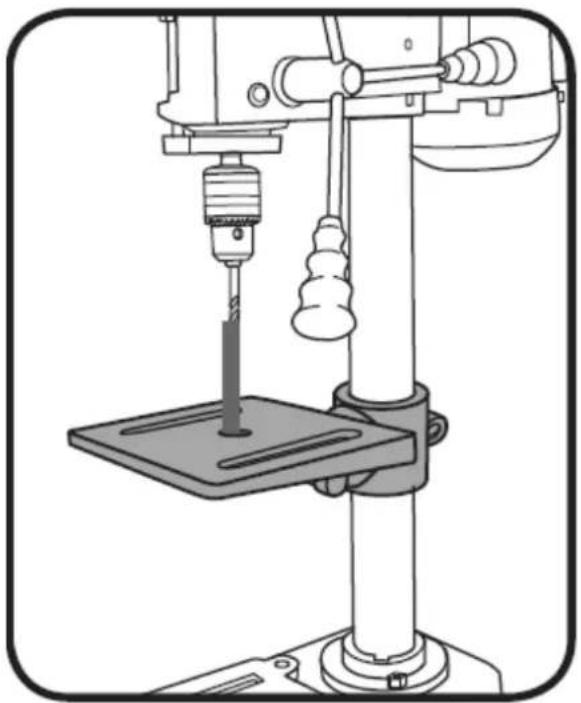
- Adjust the table to your desired height and ensure the hole in the centre of the table is aligned with the drill bit. Switch the unit on by pressing the green (I) button.
natural_image
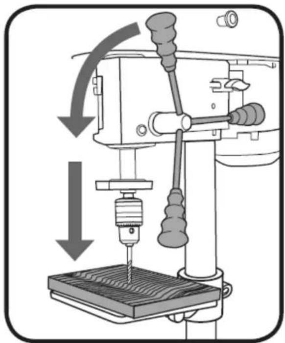
Line drawing of a mechanical press or drill machine with a central drill bit and base platform (no text or symbols)- Slowly rotate the feed wheel handles to bring the drill bit down towards the table and into your workpiece. After drilling a hole, release the feed wheel handles slowly to return the chuck to its original position.
natural_image
Diagram of a sewing machine with a drill bit and mechanical components, showing no text or symbols.- Continue the operation until the task is completed. When completed, switch the drill press off by pressing the red (0) button on the switch.
3.4. Cleaning and maintenance
a) Unplug the mains plug and allow the device to cool completely before each cleaning, adjustment or replacement of accessories, or if the device is not being used.
• Wait for the rotating elements to stop.
b) Use only non-corrosive cleaners to clean the surface.
c) After cleaning the device, all parts should be dried completely before using it again.
d) Store the unit in a dry, cool place, free from moisture and direct exposure to sunlight.
e) Do not spray the device with a water jet or submerge it in water.
f) Do not allow water to get inside the device through vents in the housing of the device.
g) Clean the vents with a brush and compressed air.
h) The device must be regularly inspected to check its technical efficiency and spot any damage.
i) Use a soft, damp cloth for cleaning.
j) Do not use sharp and/or metal objects for cleaning (e.g. a wire brush or a metal spatula) because they may damage the surface material of the appliance.
k) Do not clean the device with an acidic substance, agents of medical purposes, thinners, fuel, oils or other chemical substances because it may damage the device.
I) Ball bearings are packed with grease at the factory. No further lubrication of bearings is required.
m) Lubricate all moving parts periodically. Wipe the column, table and base with an oily cloth to minimise corrosion.
n) Keep air vents clean of dust and dirt.
o) Remove dust and dirt from the drill press regularly with a soft cloth, brush or compressed air.
p) If the power cord is damaged, have it replaced by an electrician or a power tool repairer.
q) Regularly check that all bolts, screws and nuts are securely fixed as these could work loose during normal operation.
r) If the drive belt will not align with the pulleys. The pulleys may be worn and need to be replaced. To remove the pulleys, use the 3mm hex key provided. Loosen in an anticlockwise direction.
DISPOSING OF USED DEVICES:
Do not dispose of this device in municipal waste systems. Hand it over to an electric and electrical device recycling and collection point. Check the symbol on the product, instruction manual and packaging. The plastics used to construct the device can be recycled in accordance with their markings. By choosing to recycle you are making a significant contribution to the protection of our environment.
Contact local authorities for information on your local recycling facility.

natural_image
Close-up of a mechanical drilling rig with visible components and mounting base (no text or symbols)


natural_image
Close-up of a drill bit on a wooden surface with labeled components (no text or symbols beyond labels)
natural_image
Mechanical assembly diagram showing a tool inserted into a component, with no visible text or symbolsnatural_image
Technical line drawing of a mechanical device with arrows indicating assembly or force direction (no text or symbols)natural_image
Mechanical lever mechanism diagram showing pivot and pivot components (no text or labels)natural_image
Diagram of a mechanical press or drill bit pressing down on a wooden surface, with arrows indicating force direction (no text or symbols present)natural_image
Illustration of a drill bit with a tool and directional arrow indicating rotation (no text or symbols)natural_image
Diagram of a drill bit with upward arrows indicating compression or direction (no text or symbols)natural_image
Diagram of a mechanical device with a lever and directional arrows indicating motion (no text or symbols)natural_image
Technical illustration of a drill press machine with a drill bit and handle (no text or symbols)Zmiana prędkości
natural_image
Diagram of a drill bit with a tool and arrow indicating motion (no text or symbols)
natural_image
Diagram of a drill bit with a tool and arrow indicating rotational direction (no text or symbols)natural_image
Line drawing of a mechanical drill press with a central spindle and base platform (no text or symbols)natural_image
Diagram of a sewing machine with a drill bit and mechanical components, showing no text or symbols.natural_image
Diagram of an electrical switch panel with a valve and tubing, no text or symbols presentnatural_image
Technical line drawing of a mechanical component with concentric grooves and a base (no text or symbols)USUWANIE ZUŻYTYCH URZĄDZEŃ:
natural_image
Close-up of a mechanical drilling rig with visible components and mounting base (no text or symbols)
natural_image
Close-up of a mechanical component with a hexagonal bolt and circular head (no visible text or symbols)


natural_image
Close-up of a drill bit on a wooden surface with labeled components (no text or symbols beyond labels)


natural_image
Technical line drawing of a mechanical clamp or clamping device with a vertical rod and rectangular base (no text or symbols)natural_image
Mechanical assembly diagram showing a tool inserted into a component, with no visible text or symbolsnatural_image
Technical line drawing of a mechanical device with arrows indicating assembly or force direction (no text or symbols)natural_image
Mechanical lever mechanism diagram showing pivot and pivot components (no text or labels)natural_image
Diagram of a mechanical press or drill bit pressing down on a wooden surface, with arrows indicating force direction (no text or symbols present)natural_image
Illustration of a drill bit with a tool and directional arrow indicating rotation (no text or symbols)natural_image
Diagram of a drill bit with directional arrows indicating compression or movement (no text or symbols)natural_image
Diagram of a mechanical device with a lever and rotating arrow, no text or symbols presentnatural_image
Technical line drawing of a mechanical clamp or fixture assembly (no text or symbols)
natural_image
Diagram of a drill press machine with a vertical double-headed arrow indicating compression or lifting (no text or symbols present)natural_image
Mechanical diagram showing a tool interacting with a mechanical component, including a wrench and a gear (no text or symbols present)
VAROVÁNÍ: POKUD JE STŮL NAKLONĚNÝ/NAKLONĚNÝ, ZAJISTĚTE, ŽE JE OBROBEK UPNUT NA STŮL
natural_image
Technical illustration of a drill press machine with a downward arrow indicating force or direction (no text or symbols present)Změna rychlosti
natural_image
Mechanical assembly diagram showing a lever mechanism with a rotating head and adjustment arrow (no text or symbols)natural_image
Mechanical assembly diagram showing a piston and crankshaft mechanism with directional arrows (no text or labels)natural_image
Diagram of a mechanical assembly with a rotating component and directional arrows indicating motion (no text or symbols)natural_image
Diagram of a mechanical tool with a rotating shaft and handle, showing motion direction (no text or symbols)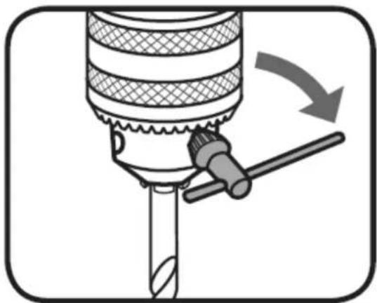
natural_image
Diagram of a drill bit with a tool and arrow indicating rotation (no text or symbols)natural_image
Line drawing of a mechanical drill press with a central spindle and base plate (no text or symbols)natural_image
Diagram of a sewing machine with a drill bit and base, showing mechanical components and directional arrows (no text or symbols)natural_image
Diagram of a mechanical or electrical device with no visible text, numbers, or symbols3.4. ČISTĚNÍ A ÚDRŽBA
natural_image
Close-up of a mechanical drilling rig with visible components and mounting base (no text or symbols)

natural_image
Close-up of a mechanical component with a hexagonal bolt and circular head (no visible text or symbols)


natural_image
Technical line drawing of a mechanical clamp or clamping device with a vertical rod and rectangular base (no text or symbols)natural_image
Mechanical assembly diagram showing a tool inserted into a component, with no visible text or symbolsnatural_image
Technical line drawing of a mechanical device with arrows indicating assembly or force direction (no text or symbols)natural_image
Mechanical lever mechanism diagram showing pivot and pivot components (no text or labels)natural_image
Diagram of a mechanical press or drill bit pressing down on a wooden surface, with arrows indicating force direction (no text or symbols present)natural_image
Illustration of a drill bit with a tool and directional arrow (no text or symbols)natural_image
Diagram of a drill bit with upward arrows indicating compression or direction (no text or symbols)natural_image
Diagram of a mechanical device with a lever and rotating arrow, no text or symbols presentnatural_image
Technical illustration of a drill press machine with a drill bit and handle (no text or symbols)Changer la vitesse
natural_image
Mechanical assembly diagram showing a rotating component with a circular head and arrow indicating rotation (no text or symbols)natural_image
Mechanical assembly diagram showing a lever mechanism with no visible text or symbolsnatural_image
Diagram of a mechanical assembly with a rotating component and directional arrows indicating motion (no text or symbols)natural_image
Diagram of a drill bit with a tool and arrow indicating motion (no text or symbols)
natural_image
Diagram of a drill bit with a tool and arrow indicating rotational direction (no text or symbols)natural_image
Line drawing of a mechanical drill press with a central spindle and base plate (no text or symbols)natural_image
Diagram of a sewing machine with a drill bit and mechanical components, showing no text or symbols.natural_image
Diagram of an electrical switch panel with a valve and tubing, no text or symbols presentnatural_image
Technical line drawing of a mechanical component with threaded base and mounting holes (no text or symbols)natural_image
Close-up of a mechanical drilling rig with visible components and mounting base (no text or symbols)

natural_image
Close-up of a mechanical component with a hexagonal bolt and circular head (no visible text or symbols)


natural_image
Close-up of a drill bit on a wooden surface with labeled components (no text or symbols beyond labels)

natural_image
Technical line drawing of a mechanical clamp or clamp device with a vertical rod and rectangular base (no text or symbols)natural_image
Mechanical assembly diagram showing a tool inserted into a component, with no visible text or symbolsnatural_image
Technical line drawing of a mechanical device with arrows indicating assembly or force direction (no text or symbols)natural_image
Mechanical lever diagram showing pivot and pivot mechanism (no text or symbols)natural_image
Diagram of a mechanical press or drill bit pressing down on a wooden surface, with arrows indicating force direction (no text or symbols present)natural_image
Illustration of a drill bit with a tool and directional arrow indicating rotation (no text or symbols)natural_image
Diagram of a drill bit with upward arrows indicating compression or direction (no text or symbols)natural_image
Diagram of a mechanical device with a lever and directional arrows indicating motion (no text or symbols)natural_image
Technical line drawing of a mechanical clamp or fixture assembly (no text or symbols)
natural_image
Illustration of a mechanical drill press with a vertical double-headed arrow indicating upward motion (no text or symbols)natural_image
Mechanical diagram showing a tool interacting with a wrench and a gear, with no visible text or symbols.
natural_image
Technical illustration of a drill press machine with a drill bit and handle (no text or symbols)natural_image
Mechanical assembly diagram showing a rotating component with a circular head and arrow indicating rotation (no text or symbols)natural_image
Mechanical assembly diagram showing a lever mechanism with no visible text or symbolsnatural_image
Diagram of a mechanical assembly with a rotating component and directional arrows indicating motion (no text or symbols)natural_image
Diagram of a drill bit with a tool and arrow indicating motion (no text or symbols)
natural_image
Diagram of a drill bit with a tool and arrow indicating rotational direction (no text or symbols)natural_image
Line drawing of a mechanical drill press with a central spindle and base plate (no text or symbols)natural_image
Diagram of a sewing machine with a drill bit and mechanical components, showing no text or symbols.natural_image
Diagram of an electrical switch panel with a valve and tubing, no text or symbols presentnatural_image
Technical line drawing of a mechanical component with threaded base and mounting base (no text or symbols)SMALTIMENTO DEI DISPOSITIVI USATI:
natural_image
Close-up of a mechanical drilling rig with visible components and mounting base (no text or symbols)

natural_image
Close-up of a mechanical component with a hexagonal bolt and circular head (no visible text or symbols)


natural_image
Close-up of a drill bit on a wooden surface with labeled components (no text or symbols beyond labels)


natural_image
Technical line drawing of a mechanical clamp or clamping device with a vertical rod and rectangular base (no text or symbols)natural_image
Technical line drawing of a mechanical assembly with a tool inserted, no visible text or symbolsnatural_image
Technical line drawing of a mechanical device with arrows indicating downward force or connection points (no text or symbols present)natural_image
Mechanical lever mechanism diagram showing pivot and pivot components (no text or labels)natural_image
Diagram of a mechanical press or drill bit pressing down on a wooden surface, with arrows indicating force direction (no text or symbols present)natural_image
Illustration of a drill bit with a tool and directional arrow indicating rotation (no text or symbols)natural_image
Diagram of a drill bit with upward arrows indicating compression or direction (no text or symbols)natural_image
Diagram of a mechanical device with a lever and directional arrows indicating motion (no text or symbols)natural_image
Technical line drawing of a mechanical clamp or fixture assembly (no text or symbols)
natural_image
Diagram of a drill press with a vertical double-headed arrow indicating upward motion (no text or symbols present)natural_image
Mechanical diagram showing a tool interacting with a wrench and a gear, with no visible text or symbols.
ADVERTENCIA: CUANDO LA MESA ESTÉ ANGULADA/INCLINADA, ASEGÚRESE DE QUE LA PIEZA DE O ESTÉ SUJETA A LA MESA
natural_image
Technical illustration of a drill press machine with a drill bit and handle (no text or symbols)natural_image
Mechanical assembly diagram showing a rotating tool with a circular component and curved components (no text or labels)natural_image
Mechanical assembly diagram showing a lever mechanism with no visible text or symbolsnatural_image
Diagram of a mechanical assembly with a rotating component and spring-loaded parts (no text or symbols)natural_image
Diagram of a drill bit with a tool and arrow indicating motion (no text or symbols)
natural_image
Diagram of a drill bit with a tool and arrow indicating rotational direction (no text or symbols)natural_image
Line drawing of a mechanical drill press with a central spindle and base plate (no text or symbols)natural_image
Diagram of a sewing machine with a drill bit and mechanical components, showing no text or symbols.natural_image
Diagram of an electrical switch panel with a circular button labeled '01' and a downward arrow pointing to it, connected to a pipe and bolt (no text or symbols beyond basic labels)natural_image
Technical line drawing of a mechanical component with concentric grooves and a base (no text or symbols)natural_image
Close-up of a mechanical drilling rig with visible components and mounting base (no text or symbols)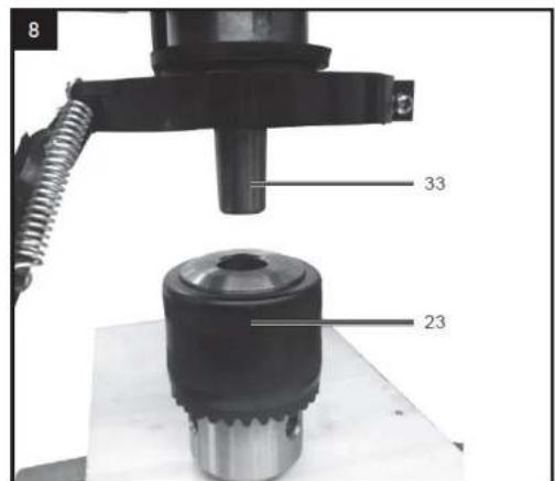

natural_image
Close-up of a mechanical component with a hexagonal bolt and circular head (no visible text or symbols)


HU


natural_image
Close-up of a drill bit on a wooden surface with labeled components (no text or symbols beyond labels)
natural_image
Mechanical assembly diagram showing a tool inserted into a component, with no visible text or symbolsnatural_image
Technical line drawing of a mechanical device with arrows indicating assembly or force direction (no text or symbols)natural_image
Mechanical lever mechanism diagram showing pivot and pivot components (no text or labels)natural_image
Diagram of a mechanical press or drill bit pressing down on a wooden surface, with arrows indicating force direction (no text or symbols present)natural_image
Illustration of a drill bit with a tool and directional arrow indicating rotation (no text or symbols)natural_image
Diagram of a drill bit with directional arrows indicating compression or movement (no text or symbols)natural_image
Diagram of a mechanical device with a lever and directional arrows indicating motion (no text or symbols)natural_image
Technical line drawing of a mechanical clamp or fixture assembly (no text or symbols)
natural_image
Diagram of a drill press with a vertical double-headed arrow indicating measurement or alignment (no text or symbols present)natural_image
Mechanical diagram showing a tool interacting with a mechanical component, including a wrench and a gear (no text or symbols present)
FIGYELMEZTETÉS: HA AZ ASZTAL FERDE/DÖNTÖTT, ÜGYELJEN ARRA, HOGY A MUNKADARABOT AZ HOZ RÖGZÍTSE.
natural_image
Technical illustration of a drill press machine with a drill bit and handle (no text or symbols)natural_image
Mechanical assembly diagram showing a rotating component with a circular head and arrow indicating rotation (no text or symbols)natural_image
Mechanical assembly diagram showing a lever mechanism with no visible text or symbolsnatural_image
Diagram of a mechanical assembly with a rotating component and directional arrows indicating motion (no text or symbols)natural_image
Diagram of a drill bit with a tool and arrow indicating motion (no text or symbols)
natural_image
Diagram of a drill bit with a tool and arrow indicating rotational direction (no text or symbols)natural_image
Line drawing of a mechanical drill press with a central spindle and base plate (no text or symbols)natural_image
Diagram of a sewing machine with a drill bit and mechanical components, showing no text or symbols.natural_image
Diagram of an electrical switch panel with a valve and tubing, no text or symbols presentnatural_image
Technical line drawing of a mechanical component with threaded base and mounting holes (no text or symbols)A HASZNÁLT ESZKÖZÖK ÁRTALMATLANÍTÁSA:
natural_image
Close-up of a mechanical drilling rig with visible components and mounting base (no text or symbols)

natural_image
Close-up of a mechanical component with a hexagonal bolt and circular head (no visible text or symbols)


DA


natural_image
Close-up of a drill bit on a wooden surface with labeled components (no text or symbols beyond labels)


natural_image
Technical line drawing of a mechanical clamp or clamping device with a vertical rod and rectangular base (no text or symbols)DA
natural_image
Mechanical assembly diagram showing a lever mechanism with a circular inset detail (no text or symbols)natural_image
Technical line drawing of a mechanical device with arrows indicating assembly or force direction (no text or symbols)natural_image
Mechanical lever mechanism diagram showing pivot and pivot components (no text or labels)natural_image
Diagram of a mechanical press or drill bit pressing down on a wooden surface, with arrows indicating force direction (no text or symbols present)natural_image
Illustration of a drill bit with a tool and directional arrow indicating rotation (no text or symbols)- Sæt boret helt ind i borepatronen.
natural_image
Diagram of a drill bit with directional arrows indicating compression or movement (no text or symbols)natural_image
Diagram of a mechanical device with a lever and rotating arrow, no text or symbols presentnatural_image
Technical line drawing of a mechanical clamp or fixture assembly (no text or symbols)
natural_image
Diagram of a mechanical press or drill machine with a vertical dimension arrow indicating measurement (no text or symbols present)natural_image
Mechanical assembly diagram showing a tool interacting with a bracket and wrench, with no visible text or symbols.
ADVARSEL: NÄR BORDET ER VINKLET, SKAL DU SIKRE DIG, AT ARBEJDSEMNET ER FASTSPÄNDT TIET
Forudindstilling af boredybden
natural_image
Technical illustration of a drill press machine with a drill bit and handle (no text or symbols)natural_image
Mechanical assembly diagram showing a lever mechanism with a rotating head and curved guide rails (no text or symbols)natural_image
Diagram of a drill bit with a tool and arrow indicating motion (no text or symbols)
natural_image
Diagram of a drill bit with a tool and arrow indicating rotation (no text or symbols)natural_image
Line drawing of a mechanical drill press with a central spindle and base platform (no text or symbols)natural_image
Diagram of a sewing machine with a drill bit and mechanical components, showing no text or symbolsnatural_image
Diagram of a mechanical or electrical device with no visible text, numbers, or symbolsnatural_image
Technical line drawing of a mechanical component with concentric grooves and a base (no text or symbols)BORTSKAFFELSE AF BRUGTE ENHEDER:
natural_image
Close-up of a mechanical drilling rig with visible components and mounting bracket (no text or symbols)


natural_image
Close-up of a drill bit on a wooden surface with labeled components (no text or symbols beyond labels)


natural_image
Technical line drawing of a mechanical clamp or clamping device with a vertical rod and rectangular base (no text or symbols)natural_image
Mechanical assembly diagram showing a lever mechanism with a circular inset detail (no text or symbols)natural_image
Technical line drawing of a mechanical device with arrows indicating assembly or force direction (no text or symbols)natural_image
Mechanical lever mechanism diagram showing pivot and pivot components (no text or labels)natural_image
Diagram of a mechanical press or drill bit pressing down on a wooden surface, with arrows indicating force direction (no text or symbols present)natural_image
Illustration of a drill bit with a tool and directional arrow indicating rotation (no text or symbols)natural_image
Diagram of a drill bit with directional arrows indicating compression or movement (no text or symbols)natural_image
Diagram of a mechanical device with a lever and rotating arrow, no text or symbols presentnatural_image
Technical line drawing of a mechanical clamp or fixture assembly (no text or symbols)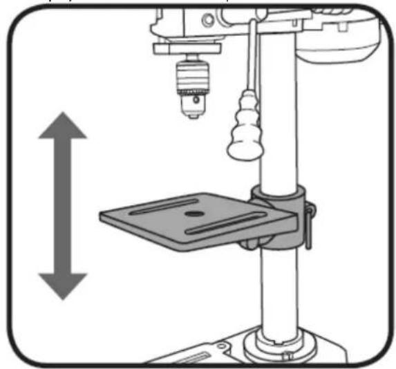
natural_image
Diagram of a mechanical press or drill machine with a vertical dimension arrow indicating measurement (no text or symbols present)Pöydän kulman säätö
natural_image
Mechanical diagram showing a tool interacting with a wrench and a drill bit, with no visible text or symbols.
VAROITUS: KUN PÖYTÄ ON KULMASSA/KALLISTUNA, VARMISTA, ETTÄ TYÖKAPPALE KIINNISITETTY
PÖYTÄ
natural_image
Technical illustration of a drill press machine with a downward arrow indicating force or direction (no text or symbols present)natural_image
Mechanical assembly diagram showing a lever mechanism with a rotating head and gear (no text or symbols)natural_image
Mechanical assembly diagram showing a lever mechanism with no text or symbolsnatural_image
Diagram of a mechanical assembly with a rotating component and directional arrows indicating motion (no text or symbols)natural_image
Diagram of a drill bit with a tool and arrow indicating motion (no text or symbols)
natural_image
Diagram of a drill bit with a tool and arrow indicating rotation (no text or symbols)natural_image
Line drawing of a mechanical drill press with a central spindle and base platform (no text or symbols)natural_image
Diagram of a sewing machine with a drill bit and base, showing mechanical components and directional arrows (no text or symbols)natural_image
Technical line drawing of a mechanical component with concentric grooves and a base (no text or symbols)KÄYTETTYJEN LAITTEIDEN HÄVITTÄMINEN:
natural_image
Close-up of a mechanical drilling rig with visible components and mounting bracket (no text or symbols)

natural_image
Close-up of a mechanical component with a hexagonal bolt and circular head (no visible text or symbols)


natural_image
Close-up of a drill bit on a wooden surface with labeled components (no text or symbols beyond labels)
NL
NL
natural_image
Mechanical assembly diagram showing a tool inserted into a component, with no visible text or symbolsnatural_image
Technical line drawing of a mechanical device with arrows indicating assembly or force direction (no text or symbols)natural_image
Mechanical lever mechanism diagram showing pivot and pivot components (no text or labels)natural_image
Diagram of a mechanical press or drill bit pressing down on a wooden surface, with arrows indicating force direction (no text or symbols present)natural_image
Illustration of a drill bit with a tool and directional arrow indicating rotation (no text or symbols)natural_image
Diagram of a drill bit with upward arrows indicating compression or direction (no text or symbols)natural_image
Diagram of a mechanical device with a lever and directional arrows indicating motion (no text or symbols)natural_image
Technical line drawing of a mechanical clamp or fixture assembly (no text or symbols)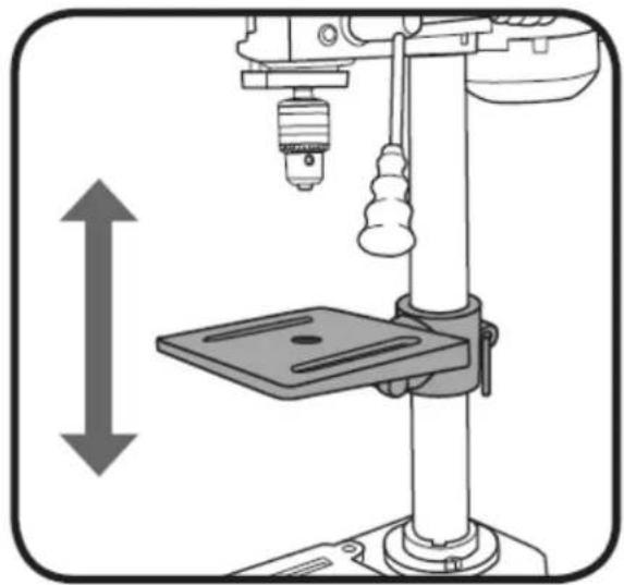
natural_image
Illustration of a mechanical drill press with a vertical double-headed arrow indicating compression or lifting (no text or symbols present)natural_image
Mechanical diagram showing a tool interacting with a mechanical component, including a wrench and a gear (no text or symbols present)
WAARSCHUWING: WANNEER DE TAFEL HOEKIG/GEKANTELD IS, MOET U ERVOOR ZORGEN DAT HET WERKSTUK AAN DE TAFEL IS GEKLEMST
natural_image
Technical illustration of a drill press machine with a drill bit and handle (no text or symbols)natural_image
Mechanical assembly diagram showing a rotating tool with a circular component and curved components (no text or labels)natural_image
Mechanical assembly diagram showing a lever mechanism with no visible text or symbolsnatural_image
Diagram of a mechanical assembly with a rotating component and directional arrows indicating motion (no text or symbols)natural_image
Diagram of a drill bit with a tool and arrow indicating motion (no text or symbols)
natural_image
Diagram of a drill bit with a tool and arrow indicating rotation (no text or symbols)natural_image
Line drawing of a mechanical drill press with a central spindle and base platform (no text or symbols)natural_image
Diagram of a sewing machine with a drill bit and mechanical components, showing no text or symbols.natural_image
Diagram of an electrical switch panel with a valve and tubing, no text or symbols presentnatural_image
Close-up of a mechanical drilling rig with visible components and a numbered label (7, 9), no readable text or symbols present.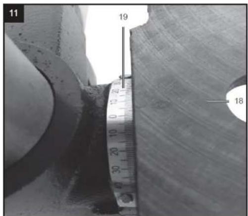


natural_image
Close-up of a drill bit on a wooden surface with labeled components (no text or symbols beyond labels)

natural_image
Technical line drawing of a mechanical clamp or clamp device with a vertical rod and rectangular base (no text or symbols)NO
-
Bunnplate
-
Borebordholder
-
Høydejusteringsspak
-
Tannet stativsøyle
-
Kolonne
-
Skru
-
Ring
-
Maskinhode
-
Håndtak
-
Dybdestopp
-
riflet mutter
-
Stopp
-
Motor
-
Beltebeskyttelse
-
Låseskrue
-
Chuck guard
-
Slisskrue
-
Borebord
-
Vinkelskala
-
Skru 90° feste
-
Klemmehåndtak for høydejustering
-
Klemskrue for borebord
-
Tannhjulschuck
-
På/av-bryter
-
Laser på/av-bryter
-
Chuck nøkkel
-
Fjærhette
-
Rille
-
Ytre mutter
-
Innermutter
-
Hakk
-
Hub
-
Spindel
-
Låsemutter
-
Skrue
-
Drivreim
-
Vingeskrue
-
Remskiver
natural_image
Technical line drawing of a mechanical assembly with a tool inserted, no visible text or symbols- Løft hodeenheten og skyv den ned på søylen så langt den går. Roter hodet slik at det er på linje med basen.
natural_image
Technical line drawing of a mechanical device with arrows indicating assembly or force direction (no text or symbols)natural_image
Mechanical lever mechanism diagram showing pivot and pivot shaft assembly (no text or labels)natural_image
Diagram of a mechanical press or drill bit pressing down on a wooden surface, with arrows indicating force direction (no text or symbols present)natural_image
Illustration of a drill bit with a tool and directional arrow indicating rotation (no text or symbols)natural_image
Technical line drawing of a mechanical clamp or fixture assembly (no text or symbols)
natural_image
Diagram of a mechanical press or drill machine with a vertical dimension arrow indicating measurement (no text or symbols present)natural_image
Mechanical diagram showing a tool interacting with a wrench and a drill bit, with no visible text or symbols.
ADVARSEL: NÅR BORDET ER VINKELT/VILTET, S∅RG FOR AT ARBEIDSTYKKET ER KLEMMT TIL
natural_image
Technical illustration of a drill press machine with a downward arrow indicating force or direction (no text or symbols present)natural_image
Mechanical assembly diagram showing a lever mechanism with a rotating head and curved guide rails (no text or symbols)natural_image
Line drawing of a mechanical press or drill machine with a central drill bit and base platform (no text or symbols)natural_image
Diagram of a sewing machine with a drill bit and mechanical components, showing no text or symbols.natural_image
Technical line drawing of a mechanical component with concentric grooves and a base (no text or symbols)KASSERING AV BRUKTE ENHETER:
natural_image
Close-up of a mechanical drilling rig with visible components and mounting base (no text or symbols)

natural_image
Close-up of a mechanical component with a hexagonal bolt and circular head (no visible text or symbols)


natural_image
Close-up of a drill bit on a wooden surface with labeled components (no text or symbols beyond labels)


natural_image
Technical line drawing of a mechanical clamp or clamping device with a vertical rod and rectangular base (no text or symbols)SE
natural_image
Technical line drawing of a mechanical assembly with a tool inserted, no visible text or symbolsnatural_image
Technical line drawing of a mechanical device with arrows indicating assembly or force direction (no text or symbols)natural_image
Mechanical lever mechanism diagram showing pivot and pivot components (no text or labels)natural_image
Diagram of a mechanical press or drill bit pressing down on a wooden surface, with arrows indicating force direction (no text or symbols present)natural_image
Illustration of a drill bit with a tool and directional arrow indicating rotation (no text or symbols)- Sätt in borrspetsen helt i chucken med kil.

natural_image
Diagram of a drill bit with upward arrows indicating compression or movement (no text or symbols)natural_image
Diagram of a mechanical device with a lever and rotating arrow, no text or symbols presentnatural_image
Technical illustration of a drill press machine with a downward arrow indicating force or direction (no text or symbols present)Ändra hastigheten
natural_image
Mechanical assembly diagram showing a lever mechanism with a rotating head and adjustment arrow (no text or symbols)natural_image
Mechanical assembly diagram showing a lever mechanism with no visible text or symbolsnatural_image
Diagram of a mechanical assembly with a rotating component and directional arrows indicating motion (no text or symbols)natural_image
Diagram of a drill bit with a tool and arrow indicating motion (no text or symbols)
natural_image
Diagram of a drill bit with a tool and arrow indicating rotation (no text or symbols)natural_image
Technical line drawing of a drill press machine with a central drill bit and base platform (no text or symbols)natural_image
Diagram of a sewing machine with a drill bit and base, showing mechanical components and directional arrows (no text or symbols)natural_image
Technical line drawing of a mechanical component with concentric grooves and a base (no text or symbols)KASSERING AV ANVÄNDA APPARATER:
natural_image
Close-up of a mechanical drilling rig with visible components and mounting base (no text or symbols)

natural_image
Close-up of a mechanical component with a hexagonal bolt and circular head (no visible text or symbols)


natural_image
Close-up of a drill bit on a wooden surface with labeled components (no text or symbols beyond labels)
PT


natural_image
Technical line drawing of a mechanical clamp or clamping device with a vertical rod and rectangular base (no text or symbols)natural_image
Mechanical assembly diagram showing a tool inserted into a component, with no visible text or symbolsnatural_image
Technical line drawing of a mechanical device with arrows indicating downward force or connection points (no text or symbols present)natural_image
Mechanical lever diagram showing pivot and pivot shaft assembly (no text or labels)natural_image
Diagram of a drill bit with upward arrows indicating compression or direction (no text or symbols)natural_image
Diagram of a mechanical device with a lever and rotating arrow, no text or symbols presentnatural_image
Technical line drawing of a mechanical clamp or fixture assembly (no text or symbols)
natural_image
Diagram of a drill press machine with a vertical double-headed arrow indicating compression or lifting (no text or symbols present)natural_image
Mechanical assembly diagram showing a tool interacting with a bracket and wrench, with no visible text or symbols.
AVISO: QUANDO A MESA ESTIVER ANGULAR/INCLINADA, CERTIFIQUE-SE DE QUE A PEÇA ESTÁ À MESA
natural_image
Mechanical assembly diagram showing a piston and crankshaft mechanism with directional arrows (no text or labels)natural_image
Diagram of a mechanical assembly with a rotating component and directional arrows indicating motion (no text or symbols)natural_image
Diagram of a drill bit with a tool and arrow indicating motion (no text or symbols)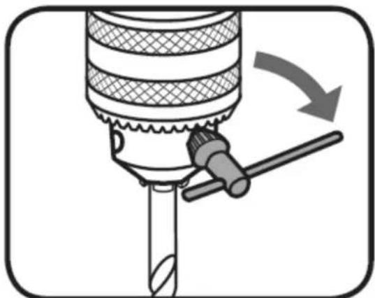
natural_image
Diagram of a drill bit with a tool and arrow indicating rotation (no text or symbols)natural_image
Line drawing of a mechanical drill press with a central spindle and base platform (no text or symbols)natural_image
Diagram of a sewing machine with a drill bit and mechanical components, showing no text or symbolsnatural_image
Diagram of a mechanical or electrical device with no visible text, numbers, or symbolsnatural_image
Technical line drawing of a mechanical component with concentric grooves and a base (no text or symbols)natural_image
Close-up of a mechanical drilling rig with visible components and mounting base (no text or symbols)

natural_image
Close-up of a mechanical component with a hexagonal bolt and circular head (no visible text or symbols)


natural_image
Close-up of a drill bit on a wooden surface with labeled components (no text or symbols beyond labels)

natural_image
Technical line drawing of a mechanical clamp or clamping device with a vertical rod and rectangular base (no text or symbols)natural_image
Mechanical assembly diagram showing a tool inserted into a component, with no visible text or symbolsnatural_image
Technical line drawing of a mechanical device with arrows indicating assembly or force direction (no text or symbols)natural_image
Mechanical lever mechanism diagram showing pivot and pivot components (no text or labels)natural_image
Diagram of a mechanical press or drill bit pressing down on a wooden surface, with arrows indicating force direction (no text or symbols present)natural_image
Illustration of a drill bit with a tool and directional arrow indicating rotation (no text or symbols)natural_image
Diagram of a drill bit with directional arrows indicating compression or movement (no text or symbols)natural_image
Diagram of a mechanical device with a lever and rotating arrow, no text or symbols presentnatural_image
Technical line drawing of a mechanical clamp or fixture assembly (no text or symbols)
natural_image
Diagram of a drill press machine with a vertical double-headed arrow indicating force or displacement (no text or symbols present)Nastavenie uhla stola
natural_image
Mechanical assembly diagram showing a tool interacting with a spring scale and wrench, with no visible text or symbols.
UPOZORNENIE: KEĐ JE STÔL NAKLONENÝ/NAKLONENÝ, UISTITE SA, ŽE JE OBROBOK UPNUTÝ K
STOLA
Prednastavenie híbky vrtania
natural_image
Technical illustration of a drill press machine with a downward arrow indicating force or direction (no text or symbols present)Zmena rýchlosti
natural_image
Mechanical assembly diagram showing a lever mechanism with a rotating head and adjustment arrow (no text or symbols)- Zatlačte motor smerom k hlavovému zloženiu a utiahnite gombíky napnutia remeňa.
natural_image
Mechanical assembly diagram showing a lever mechanism with no visible text or symbolsnatural_image
Diagram of a mechanical assembly with a rotating component and directional arrows indicating motion (no text or symbols)natural_image
Diagram of a mechanical tool with a rotating shaft and handle, showing motion direction (no text or symbols)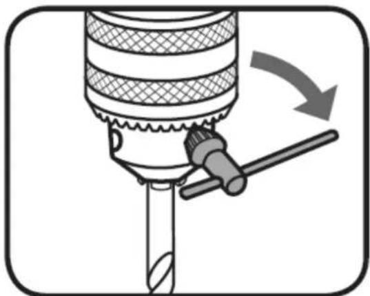
natural_image
Diagram of a drill bit with a tool and arrow indicating rotation (no text or symbols)natural_image
Technical line drawing of a drill press machine with a central drill bit and base platform (no text or symbols)natural_image
Diagram of a sewing machine with a drill bit and base, showing mechanical components and directional arrows (no text or symbols)natural_image
Technical line drawing of a mechanical component with concentric grooves and a base (no text or symbols)LIKVIDÁCIA POUŽITÝCH ZARIADENÍ:
For the disposal of the device please consider and act according to the national and local rules and regulations.
CONTACT
expondo Polska sp. z o.o. sp. k.