PPH-T500 - Drill MSW - Free user manual and instructions
Find the device manual for free PPH-T500 MSW in PDF.

User questions about PPH-T500 MSW
0 question about this device. Answer the ones you know or ask your own.
Ask a new question about this device
Download the instructions for your Drill in PDF format for free! Find your manual PPH-T500 - MSW and take your electronic device back in hand. On this page are published all the documents necessary for the use of your device. PPH-T500 by MSW.
USER MANUAL PPH-T500 MSW
This User Manual has been translated using machine translation. We have made every effort to ensure the translation is accurate, but please note that automated translations are not perfect and are not meant to replace human translators. The official version of the User Manual is in English. Any differences between the translated version and the original English are not legally binding. If you have any questions about the accuracy of the translation, please refer to the English version, which is the official reference. More language versions are available upon request via info@expondo.com.
Technical data
| Parameter description | Parameter value |
| Product name | Pneumatic planishing hammer |
| Model | MSW-PPH-T500 |
| Dimensions (Width x Length x Height) [mm] | 600x1040x500 |
| Weight [kg] | 20.8 |
Purpose
The product is a tool used for shaping and smoothing metal surfaces, particularly in metalworking and automotive repair. It operates using compressed air to drive a hammer that strikes the metal, flattening or refining its surface. This tool is ideal for tasks such as removing dents, smoothing welded seams, or creating a consistent finish on sheet metal in both workshop and manufacturing settings.
The user is liable for any damage resulting from unintended use of the product.
Assembly
- Connect Main Support (3) to Table Support (2). Insert two Bolts (6) with Washers (10) down through the Table Support (2) and Main Support (3). Slide on two more Washers (10), Spring Washers (9) and thread on the Nuts (7).
- Attach Table Support (2) to Leg (1). Insert two Bolts (4) with Washers (10) down through the Table Support (2) and down through the Leg (1). Slide on two more Washers (10), Spring Washers (9) and thread on the Nuts (7). See Figure 1 for details.
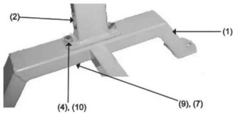
Figure 1
- Secure Cross Bar (8) to both the Main Support (3) and Leg (1). Slide Spring Washer (9) and Washer (10) onto Bolt (5). Thread in through Main Support (3) and into Cross Bar (8). From the opposite side, slide Spring Washer (9) and Washer (10) onto second Bolt (5) and thread into Leg (1) and into Cross Bar (8).
- Tighten all hardware.
- Check the stand to make certain that it sits evenly, fully resting on the ground. Make certain that all hardware is fully tightened.
- Unscrew and remove both Plugs (11) and fill the stand with sand to reduce noise when using the product. Only use sand to fill the stand. Do not use any other material or any liquid to fill the stand. Screw the Plugs back onto the stand. See Figure 2 for details.
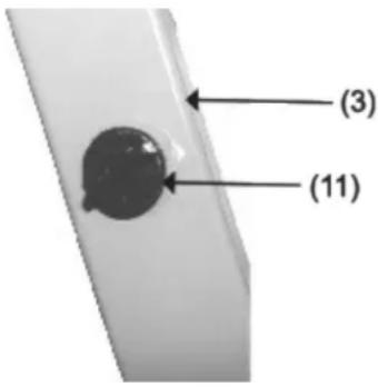
Figure 2
- Place the product on top of the stand and align the mounting holes of both stand and product. Position the operating portion of the product above the Leg (1) of the stand as shown on the cover picture.
- Secure product to the stand by sliding a grade-5 bolt (not included) of adequate length through a flat washer (not included), then through the base hole of the product, and then through the mounting plate of the stand. Slide another flat washer (not included) over the bolt. Attach a self-locking nut (not included). Repeat this operation for the remaining mounting holes. Then tighten all the nuts.
- The stand has three 7/16" holes for mounting it to your work surface (hardware not included). Ensure it is used on a flat, level surface capable of supporting the stand, the product, the metal being worked on, and the vibration from the planishing process.
Maintenance & Cleaning
- Clean the stand with a damp cloth. Do not use abrasives, harsh chemicals or detergents as these will scratch and damage the stand.
- Before each use, inspect the general condition of the stand. Check for loose fasteners, cracked or broken parts and any other condition that may affect its safe operation. Always make sure the Planer is firmly attached to the stand. Do not use damaged equipment.
Parts
Explosive view
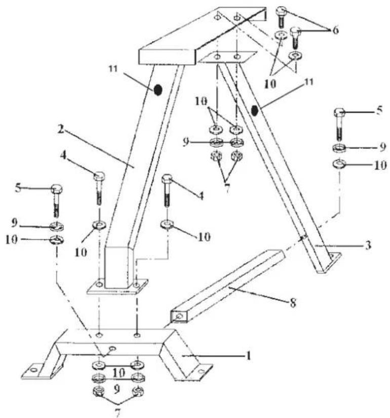
| No. Part Description |
| 1 Leg |
| 2 Table Support |
| 3 Main Support |
| 4 Bo t M 8 x 50mm |
| 5 Bo t M8 x 75mm |
| 6 Bo t M8 x 20mm |
| 7 Nut M8 |
| 8 Cross Bar |
| 9 Spring Washer |
| 10 Flat Washer |
| 11 Plug |

| Nr. Descripción de la pieza |
| 1 Pierna |
| 2 Soporte de mesa |
| 3 Soporte principal |
| 4 Perno M 8 x 50 mm |
| 5 Perno M8 x 75 mm |
| 6 Perno M8 x 20 mm |
| 7 Tuerca M8 |
| 8 Barra transversal |
| 9 Arandela de resorte |
| 10 Arandela plana |
| 11 Enchufe |

| Nr. Del Beskrivelse |
| 1 Fod |
| 2 Bordstøtte |
| 3 Hovedstøtte |
| 4 Bo t M 8 x 50 mm |
| 5 Bo t M8 x 75 mm |
| 6 Bo t M8 x 20 mm |
| 7 Møtrik M8 |
| 8 Tværstang |
| 9 Fjederskive |
| 10 Flad skive |
| 11 Stik |

| Nr. Delbeskrivelse |
| 1 Bein |
| 2 Tabellstøtte |
| 3 Hovedstøtte |
| 4 Bo t M 8 x 50mm |
| 5 Bo t M8 x 75mm |
| 6 Bo t M8 x 20mm |
| 7 Mutter M8 |
| 8 Cross Bar |
| 9 Fjærskive |
| 10 Flat skive |
| 11 Støpsel |

| Nie Popls časti |
| 1 Leg |
| 2 Podpora stola |
| 3 Hlavná podpora |
| 4 Skrutka M 8 x 50 mm |
| 5 Skrutka M8 x 75 mm |
| 6 Skrutka M8 x 20 mm |
| 7 Matica M8 |
| 8 Priečna tyč |
| 9 Pružinová podložka |
| 10 Plochá podložka |
| 11 Zástrčka |

| Ne. Opis dijela |
| 1 Noga |
| 2 Podrška za stol |
| 3 Glavna podrška |
| 4 Vijak M 8 x 50 mm |
| 5 Vijak M8 x 75 mm |
| 6 Vijak M8 x 20 mm |
| 7 Matica M8 |
| 8 Križna traka |
| 9 Opružna podloška |
| 10 Ravna podloška |
| 11 Utikač |

For the disposal of the device please consider and act according to the national and local rules and regulations.
CONTACT
expondo Polska sp. z o.o. sp. k.