HPF-01 - Hydraulic pump MSW - Free user manual and instructions
Find the device manual for free HPF-01 MSW in PDF.

| Product type | Hydraulic foot pump |
| Model | MSW-HPF-01 |
| Max oil pressure | 700 bar |
| Oil hose length | 2 m |
| Air consumption | 255 L/min |
| Required air pressure | 0.3 to 1 MPa |
| Dimensions (L×W×H) | 135 × 330 × 195 mm |
| Weight | 7.9 kg |
| Air inlet connection | 1/4 NPT |
| Oil outlet connection | 3/8 NPT |
| Hydraulic oil type | Oil 32# |
| Oil change interval | Every 350 hours |
| Main function | Conversion of low air pressure to high hydraulic pressure |
| Applications | Automotive manufacturing, engineering, aerospace, oil |
| Safety | Use a high-pressure hose ≥ 70 MPa |
| Recommended accessories | Oil-water separator at air inlet |
| Spare parts | Complete list of 44 parts in the manual |
| Repairability | Disassembly and cleaning of the pneumatic motor, replacement of seals and springs |
| Warranty | Legal conformity warranty (estimated) |
| Cleaning | Clean with diesel or kerosene, dry with compressed air |
Frequently Asked Questions - HPF-01 MSW
User questions about HPF-01 MSW
0 question about this device. Answer the ones you know or ask your own.
Ask a new question about this device
Download the instructions for your Hydraulic pump in PDF format for free! Find your manual HPF-01 - MSW and take your electronic device back in hand. On this page are published all the documents necessary for the use of your device. HPF-01 by MSW.
USER MANUAL HPF-01 MSW
natural_image
Orange industrial pressure vessel with coiled tubing and a black housing, no visible text or symbols on the device itself.This User Manual has been translated using machine translation. We have made every effort to ensure the translation is accurate, but please note that automated translations are not perfect and are not meant to replace human translators. The official version of the User Manual is in English. Any differences between the translated version and the original English are not legally binding. If you have any questions about the accuracy of the translation, please refer to the English version, which is the official reference. More language versions are available upon request via info@expondo.com.
Technical data
| Parameter description Parameter value | |
| Product name Hydraulic foot pump | |
| Model | MSW-HPF-01 |
| Capacity max oil pressure [bar] 700 | |
| Oil hose length [meter] 2 | |
| Air pressure [kg/cm3] | 1.7-8.6 |
| Air consumption [L/min] 255 | |
| Dimensions [width * length * height; mm] 135*330*195 | |
| Weight [kg] 7.9 | |
Description
natural_image
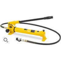
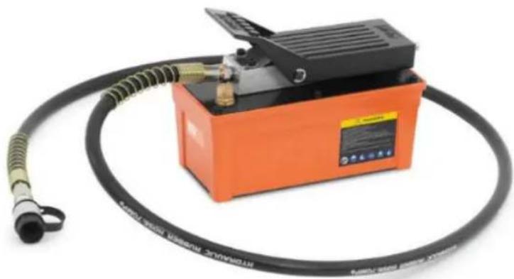
Orange industrial pressure vessel with coiled hose and attached control panel (no visible text or symbols)The product is a tool widely used across various industries, including automobile manufacturing, engineering technology, aerospace, and petroleum. Its primary function is to move hydraulic fluid to generate hydraulic power.
The pump operates by converting low air pressure into high-pressure hydraulic oil pressure. This is achieved by utilizing the low air pressure at the piston end with a large area to generate high hydraulic pressure at the piston end with a smaller area.
The user is liable for any damage resulting from unintended use of the device.
Installation
1. Air supply
The pump requires an air pressure of 0.3 to 1 MPa for operation. When the air supply is 0.67 m^3/min and the air pressure ranges from 0.65 MPa to 1 MPa, maximum oil supply and pressure are achieved. To ensure clean, lubricated air and extend the pump's lifespan, install an oil-water separator at the air intake.
The pump's intake end features a 1/4 NPT sealed pipe thread for connection to the air supply port. Wrap good-quality thread sealing tape around the pipe fitting, leaving the first thread turn free to prevent debris from entering the system, and tighten securely.
2. Hydraulic connections
The oil outlet has a 3/8 NPT sealed pipe threaded port. Use high-quality thread sealing tape on the pipe joint, leaving the first thread turn free to avoid debris in the system, then tighten it. The outlet oil pipe should be at least a 70 MPa-grade high-pressure pipe; failure to do so may result in pipe bursts or breakdowns, posing a serious risk of personal injury.
3. Vent valve (fuel filler)
Before using the pump, loosen the vent valve by 1 to 2 turns to prevent cavitation and damage to the pump. Close the vent valve when transporting the pump after use. The vent valve can also serve as an oil filler port; remove the entire vent valve from the pump cover to add hydraulic oil.
Operation
1. Checking the fluid level
Check the fluid level in the pump and follow the refuelling instructions in the section
2. The pedal operation
Oil supply: To start oil supply, set the reversing handle to the port end that will be supplied. Press the pedal to initiate oil flow to the system.
Suspend oil supply: When the pedal is in the neutral position (not pressed and not in the drain position), the pump stops running and holds the pressure.
Oil return: Rotate the reversing handle to the opposite oil port end. Press the pedal to allow the hydraulic system to return oil. To pause the return process, simply release the pedal, which will stop the return and maintain the instantaneous pressure at that moment.
3. Pump exhaust
Ensure the vent valve is open; if not, loosen it by 1 to 2 turns. Set the reversing lever to the neutral position, press the supply pedal for 3 to 5 seconds to expel any air trapped in the system, and the pump will then operate normally.
Cleaning and maintenance
1. Oil change
Hydraulic oil should be replaced every 350 hours of use. In environments with high levels of dirt, the oil change cycle should be shortened accordingly.
To change the oil, remove the case cover from the oil tank. Drain the old hydraulic oil, which may have deteriorated or become contaminated. Clean the pump body and oil tank by placing them in a cleaning
container and using clean diesel or kerosene. After drying with compressed air, refill the oil tank with clean 32# hydraulic oil and reassemble the components.
2. Air removal
Air may remain in the pump after an oil change, or air bubbles may form during transport. This can cause the air motor to run without generating hydraulic pressure. To remove the air, follow these steps:
- Connect compressed air.
- Set the reversing handle to the middle position.
- Press the pedal for 3-5 seconds to engage the air motor for 5-10 seconds.
- Check the oil port using the 4.2 oil supply instructions to see if oil leaks from the outlet. If the oil is released, the air in the pump has been expelled. If no oil is visible, repeat the process until oil emerges from the outlet.
Disposing of used devices
Do not dispose of this device in municipal waste systems. Hand it over to an electric and electrical device recycling and collection point. Check the symbol on the product, instruction manual, and packaging. The plastics used to construct the device can be recycled following their markings. By choosing to recycle you are making a significant contribution to the protection of our environment.
Contact local authorities for information on your local recycling facility.
Troubleshooting
| Problem | Possible | cause |
| 1. The air motor does not work or stops working during operation. | Long time not used, condensate in compressed air rusting air motor parts lead to:1. Round-trip valve gets stuck due to oil or water rust. | 1. Disassemble the air motor, clean the round-trip valve part and add grease. Alternatively, you can add a few drops of lubricating oil at the intake joint and then add some lubricating grease. Use compressed air to introduce it into the air motor, but this is only suitable for temporary use. |
| 2. Lubricating grease is diluted by condensate and then taken away by the air, piston ring and round-trip valve seals are badly worn, air leakage from the air motor. | 2. Replace the piston ring and round-trip valve seal. | |
| 3. The plunger reset spring and cylinder head top spring are broken. | 3. Replace the spring. | |
| 2. The pump can produce pressure but the pressure holding is not good. | 1. Damaged reversing valve spool seal. | 1. Replace the sealing ring. |
| 2. Expired or unclean oil causes the reversing valve to wear and seal poorly. | 2. Change the oil, clean the system components and replace the reversing valve part. | |
| 3. The pump can't reach the maximum pressure value. | 1. The air motor is not working properly. | 1. Check whether the intake switch and piston ring are not well sealed and leaky. |
| 2. After the impurities enter the safety valve, the seal is not good, | 2. Check the safety valve, clean the pump head. | |
| resulting in oil leakage. | ||
| 3. Same with the second cause of failure. | 3. Same with the second elimination method. |
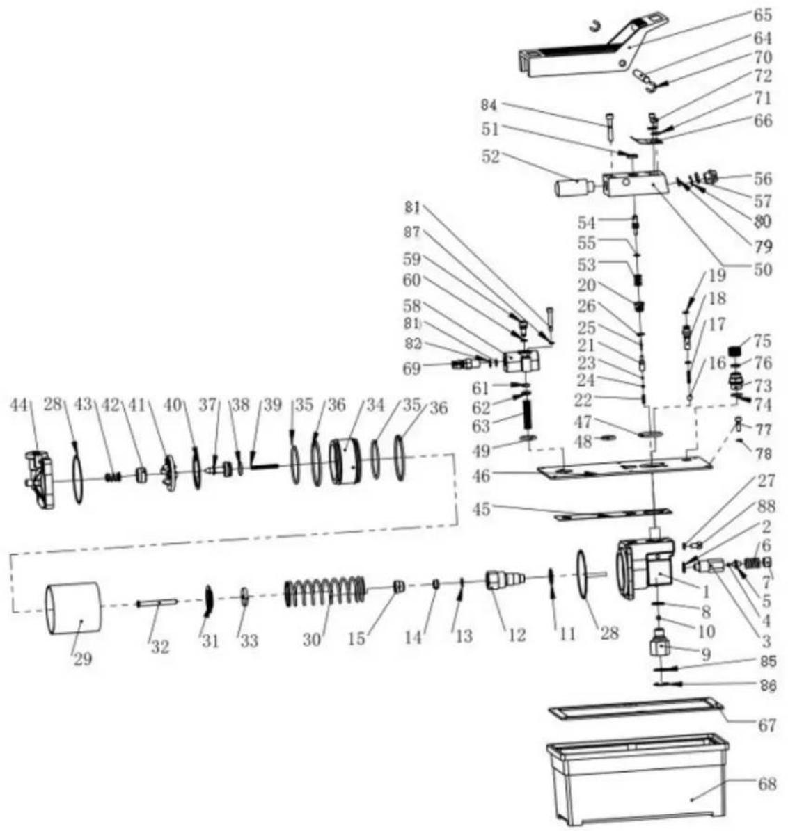
Parts diagram
| Part number | Description | Part number | Description |
| 1 plunger pump body 23 oil drain one-way valve | |||
| 2 overflow washer 24 oil drain ball holder | |||
| 3 overflow valve body 25 oil drain thimble | |||
| 4 overflow one-way | valve 26 | ||
| 5 overflow ball holder | 27 | copper washer | |
| 6 overflow spring | 28 | air cylinder seal ring | |
| 7 adjust plug | 29 | cylinder bore | |
| 8 copper washer | 30 | plunger return spring | |
| 9 oil absorption filter 31 | plunger stop plate | ||
oil
| 10 | oil absorption | one-way | valve | 32 |
| 11 | copper washer | 33 | plunger | |
| 12 | plunger | body | 34 | |
| 13 | plunger seal | washer | 35 | |
| 14 | plunger seal | washer | 36 | |
| 15 | front | cover | 37 | small |
| 16 | oil outlet one-way valve | 38 | small piston O-ring | |
| 17 | oil-stop spring | 39 | small piston return spring | |
| 18 | high-pressure oil connecting body | 40 | big piston seal washer | |
| 19 | high-pressure nozzle O-ring | 41 | big piston cover | |
| 20 | oil drain valve | 42 | small piston seal washer | |
| 21 | oil drain valve spool | 43 | cylinder head spring | |
| 22 | oil drain valve spring | 44 | back cover | |
| 45 | pump cover seal washer | 67 | reservoir seal washer | |
| 46 | reservoir cover | 68 | reservoir | |
| 47 | oil outlet O-ring | 69 | air inlet connector | |
| 48 | air vent O-ring | 70 | snap ring | |
| 49 | air inlet O-ring | 71 | washer | |
| 50 | oil outlet valve block | 72 | bolt | |
| 51 | anti-dust ring | 73 | breathing valve | |
| 52 | muffler | 74 | O-ring | |
| 53 | oil drain spring | 75 | breathing | |
| 54 | oil drain switch | 76 | seal | |
| 55 | oil drain pressure bar O-ring | 77 | bolt | |
| 56 | oil port end cap | 78 | nylon washer | |
| 57 | oil port end cap O-ring | 79 | oil return filter | |
| 58 | air inlet valve body | 80 | snap ring | |
| 59 | air inlet switch | 81 | air inlet filter | |
| 60 | air inlet switch O-ring | 82 | snap ring | |
| 61 | air inlet switch seal washer | 83 | bolt | |
| 62 | air inlet seal washer cap | 84 | bolt | |
| 63 | air inlet spring | 85 | filter | |
| 64 | pin | 86 | snap ring | |
| 65 | foot pedal | 87 | spring washer | |
| 66 | return | spring | 88 | bolt |
cap

natural_image
Orange industrial pressure testing machine with coiled tubing and control panel (no visible text or symbols)natural_image
Orange industrial pressure testing machine with coiled hose and control panel (no visible text or symbols)natural_image
Orange hydraulic pressure pump with coiled tubing and a black cover (no visible text or symbols)natural_image
Orange industrial pressure vessel with coiled tubing and a black cover, no visible text or symbols on the device itself.natural_image
Orange industrial pressure vessel with coiled tubing and a black handle, no visible text or symbols on the device itself.natural_image
Orange industrial pressure vessel with coiled tubing and a black top, no visible text or symbols on the device itself.natural_image
Orange industrial electrical device with coiled black tubing and a label, no visible text or symbols on the device itself.natural_image
Orange industrial pressure vessel with coiled tubing and a digital display (no visible text or symbols)natural_image
Orange industrial pressure vessel with black hoses and a blue cover, no visible text or symbols on the device itself.natural_image
Orange industrial hydraulic pressure testing device with coiled tubing and a black housing (no visible text or symbols)natural_image
Orange industrial pressure vessel with coiled tubing and a black handle, no visible text or symbols on the device itself.natural_image
Orange industrial pressure testing device with coiled tubing and a black handle (no visible text or symbols)natural_image
Orange industrial pressure testing machine with coiled tubing and attached control panel (no visible text or symbols)natural_image
Orange hydraulic pressure pump with coiled tubing and a black housing (no visible text or symbols)natural_image
Orange industrial pressure vessel with coiled tubing and a black housing, no visible text or symbols on the device itself.natural_image
Orange industrial pressure testing machine with coiled tubing and attached control panel (no visible text or symbols)Proizvod je alat koji se široko koristi u raznim industrijama, uključujući proizvodnju automobila, inženjersku tehnologiju, zrakoplovstvo i naftu. Njegova primarna funkcija je pomicanje hidrauličke tekućine za stvaranje hidrauličke snage.
natural_image
Orange industrial pressure vessel with coiled tubing and a black cover, no visible text or symbols on the device itself.natural_image
Orange industrial pressure vessel with coiled tubing and a black handle, no visible text or symbols on the device itself.natural_image
Orange industrial pressure pump with coiled tubing and a black housing (no visible text or symbols)For the disposal of the device please consider and act according to the national and local rules and regulations.
CONTACT
expondo Polska sp. z o.o. sp. k.