HPM-03 - Hydraulic pump MSW - Free user manual and instructions
Find the device manual for free HPM-03 MSW in PDF.

User questions about HPM-03 MSW
0 question about this device. Answer the ones you know or ask your own.
Ask a new question about this device
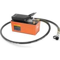
Download the instructions for your Hydraulic pump in PDF format for free! Find your manual HPM-03 - MSW and take your electronic device back in hand. On this page are published all the documents necessary for the use of your device. HPM-03 by MSW.
USER MANUAL HPM-03 MSW
natural_image
Line drawing of a mechanical device with hoses and connectors (no text or symbols)natural_image
3D mechanical assembly diagram showing a blue cylindrical component connected to two gray cables, with numbered parts labeled 1 and 2 (no text or symbols beyond labels)A

natural_image
3D mechanical device with no visible text or symbols, including a red prohibition symbol (no readable text or labels)B

C

natural_image
3D rendered image of a teal hydraulic cylinder connected to a gray cable, with no visible text or symbolsD
This User Manual has been translated using machine translation. We have made every effort to ensure the translation is accurate, but please note that automated translations are not perfect and are not meant to replace human translators. The official version of the User Manual is in English. Any differences between the translated version and the original English are not legally binding. If you have any questions about the accuracy of the translation, please refer to the English version, which is the official reference. More language versions are available upon request via info@expondo.com.
Technical data
| Parameter description Parameter value | |
| Product name Hydraulic manual pump | |
| Model | MSW-HPM-03 |
| Capacity max pressure [bar] 700 | |
| Hose length [meter] 1.8 | |
| Maximum hydraulic cylinder [ton] 100 | |
| Dimensions [width * length * height; mm] 150*2490*210 | |
| Weight [kg] 9 | |
Description
natural_image
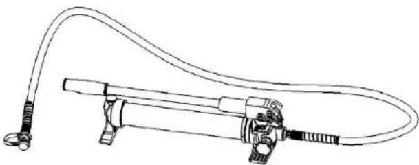
Line drawing of a mechanical device with hoses and connectors (no text or symbols)This product is used for connecting with hydraulic working heads, which is widely used in electrical construction and other construction site.
The user is liable for any damage resulting from unintended use of the device.
Operation
Components
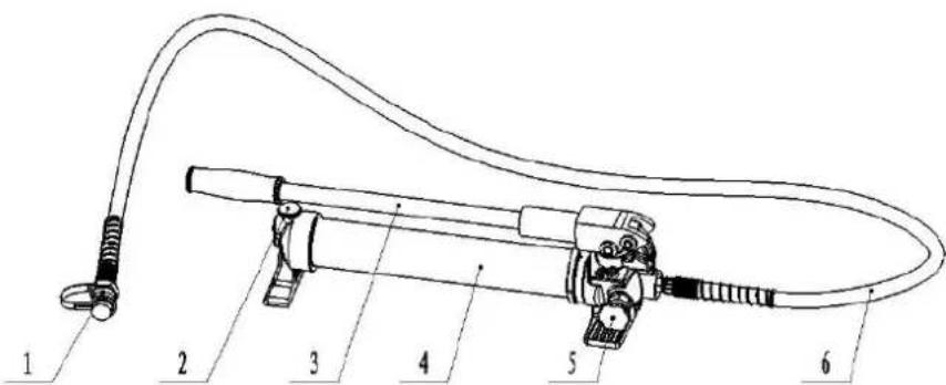
| Number | Component | name | Function |
| 1 Coupler | For connecting with the working head | ||
| 2 | Screw | For covering the oil tube to prevent oil from leaking | |
| 3 | Active | handle | For operation |
| 4 Pump body | For storing oil | ||
| 5 Turn | screw For releasing pressure | ||
| 6 Hose | For transporting oil | ||
Instructions

WARNING!
- Pumping the handle gently to make the oil flow smoothly, otherwise, it will damage the hydraulic system.
- Please do not knock any part of the tool; otherwise, it is dangerous to the operator.
Please refer the illustration below:
natural_image
3D mechanical assembly diagram showing a blue cylindrical component connected to a gray cable, with numbered annotations (1, 2) indicating parts of the pipe or valve.A
natural_image
3D diagram of a mechanical device with a labeled cable and a prohibition symbol (no text or labels present)B

C

natural_image
3D rendered image of a teal mechanical device with attached cable and fittings (no text or symbols visible)D
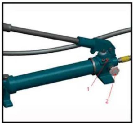
1- Built-in safety valve
2- Release pressure manually
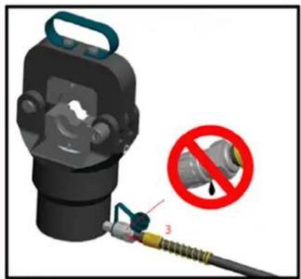
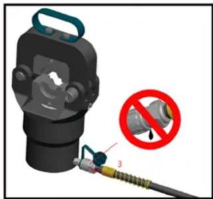
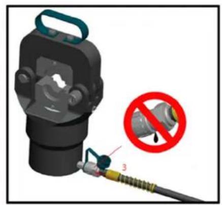
3- Connect the coupler to the other split-unit tool
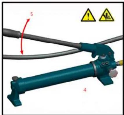
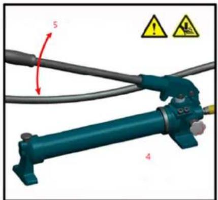
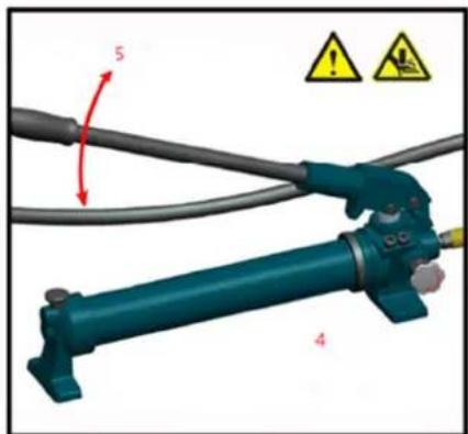
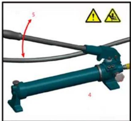
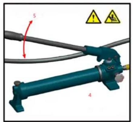
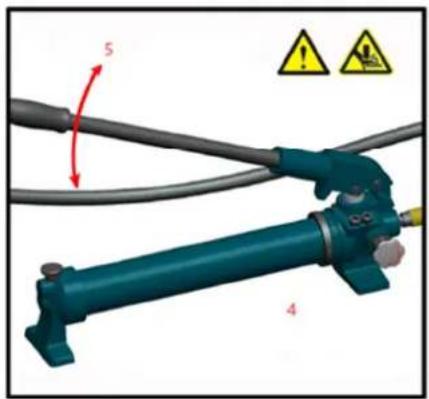
4- Before operating, spin the screw tightly in the clockwise direction
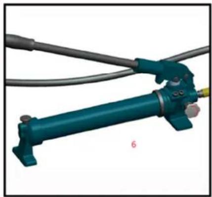
5- Pumping the handle
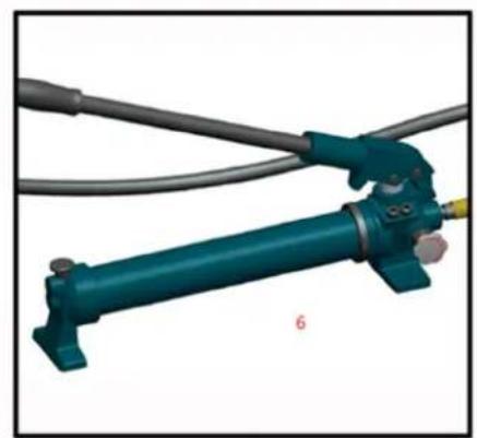
6- After operating, spin the screw in the counterclockwise direction to release pressure

DANGER! The coupler can connect the pump with another tool quickly and easily. The male and female couplers must connect well, otherwise, it may hurt the operator.
Cleaning and maintenance

WARNING!
- Damaged equipment may cause serious personal injury. Do not use damaged equipment. If abnormal noise or vibration occurs, have the problem corrected before further use.
-
The dust or air inside the tool will damage the sealing kit so causing the tool lose function. Make sure the oil is clear, and no dust enters the oil when changing oil. Wait for a while and exhaust the oil completely out of the oil tube before inserting the oil plug.
-
Before each use, inspect the general condition of the tool. Check for the coupler is clean, check for loose screws, misalignment or binding of moving parts, cracked or broken parts, or any other condition that may affect its safe operation.
- After using, clean the external surfaces of the tool with clean, moist, smear the rust-preventing oil on the metal surface of the tool and the dies to avoid rusty. Store the tool in a dry environment. The coupler should be covered by the cap in timely, otherwise, the dust will enter and pollute the oil.
- Service to the tool should only be done by a qualified Service Technician.
- To prolong the life of the tool please change the oil per year. Make sure the oil is filtered by 120 mesh net or over 30 m strainer. Meantime avoids the dust in the oil cup.
- After a long time using, the sealing kits will be damaged, if there is leakage, please contact us to change the sealing kits.

CAUTION! Please wear rubber gloves to prevent direct contact with oil. If skin contact occurs accidentally, wash the area promptly with soap and water. To protect the environment, dispose of waste oil at a government-approved treatment facility.
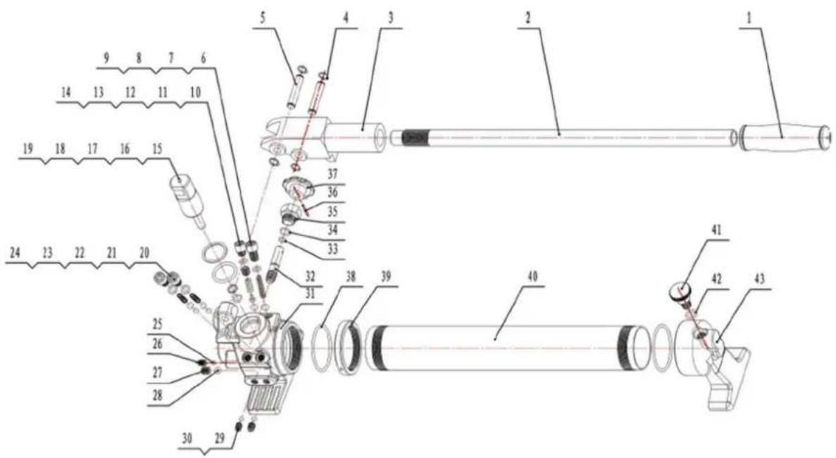
Parts diagram
| Part number Description Quantity | ||
| 1 | Hand | grip |
| 2 | Active | handle |
| 3 | Handle | hand |
| 4 Elastic snap ring 4 | ||
| 5 | Pin | 2 |
| 6 | Steel | ball |
| 7 Spring for safety valve 1 | ||
| 8 | O-ring | 1 |
| 9 Hexagonal screw (M10*16.4) 1 | ||
| 10 | Steel | ball |
| 11 Safety valve core | 1 | |
| 12 | Hexagonal screw (M10*10) | 1 |
| 13 | O-ring | 1 |
| 14 | Hexagonal screw (M10Φ8) | 1 |
| 15 | O-ring | 1 |
| 16 | Plastic ring (Φ13*Φ10*1.4) | 1 |
| 17 | O-ring | 1 |
| 18 | Plastic ring (Φ34*Φ28*1.68) | 1 |
| 19 | Plunger | 1 |
| 20 | Steel | ball (Φ6) |
| 21 | Steel | ball (Φ8) |
| 22 | Spring (Φ0.4*Φ6.8*22) | 2 |
| 23 | O-ring | 2 |
| 24 | Hexagonal screw (M10Φ13.6) | 2 |
| 25 | Steel | ball |
| 26 | Hexagonal screw (M8*10) 1 | |
| 27 | Hexagonal screw (M10*10) | 1 |
| 28 | Steel | ball |
| 29 | Steel | ball |
15
(SΦ
(SΦ
(SΦ
(SΦ
| 30 Hexagonal screw (M8*10) 2 | ||
| 31 | Pump | body |
| 32 | Valve | stem |
| 33 | O-ring | 1 |
| 34 | O-ring | 1 |
| 35 | Valve | cover |
| 36 Elastic straight pin 1 | ||
| 37 | Turn | screw |
| 38 | O-ring | 2 |
| 39 | Shaft | nut |
| 40 | Oil | sac |
| 41 | Screw | 1 |
| 42 | O-ring | 1 |
| 43 | Back | seat |

natural_image
Line drawing of a mechanical device with hoses and connectors (no text or symbols)natural_image
3D mechanical assembly diagram showing a blue cylindrical component connected to two gray cables, with numbered annotations (1, 2) pointing to specific parts.A

natural_image
3D mechanical device with no visible text or symbols, including a red prohibition symbol (no readable text or labels)B

C

natural_image
3D rendering of a teal hydraulic cylinder connected to a gray cable, with no visible text or symbolsD
natural_image
Line drawing of a mechanical device with hoses and connectors (no text or symbols)natural_image
3D mechanical assembly diagram showing a blue cylindrical component connected to a gray cable, with numbered annotations (1, 2) indicating parts of the pipe or valve.A

natural_image
3D diagram of a mechanical device with a labeled cable and a prohibition symbol (no text or labels present)B

natural_image
Mechanical assembly diagram showing a blue cylindrical component connected to a gray cable with red directional arrows and warning symbols (no readable text or labels)C

natural_image
3D rendered image of a teal mechanical device with attached cable and fittings (no text or symbols visible)D
natural_image
Line drawing of a mechanical device with hoses and connectors (no text or symbols)natural_image
3D mechanical assembly diagram showing a blue cylindrical component connected to two gray cables, with numbered annotations (1, 2) pointing to specific parts.A

natural_image
3D mechanical device with no visible text or symbols, including a red prohibition symbol (no readable text or labels)B

C

natural_image
3D rendered image of a teal hydraulic cylinder connected to a gray cable, with no visible text or symbolsD
natural_image
Line drawing of a mechanical device with hoses and connectors (no text or symbols)natural_image
3D mechanical assembly diagram showing a blue cylindrical component connected to a gray cable, with numbered parts labeled 1 and 2 (no text or symbols beyond labels)A

natural_image
3D diagram of a mechanical device with a disassembled component and a prohibition symbol (no text or labels)B
C

natural_image
3D rendered image of a blue mechanical device with attached cable and fittings (no text or symbols visible)D
natural_image
Line drawing of a mechanical device with hoses and connectors (no text or symbols)natural_image
3D mechanical assembly diagram showing a blue cylindrical component connected to a gray cable with labeled parts 1 and 2 (no text or symbols beyond labels)A

natural_image
3D diagram of a mechanical device with a disassembled component and a prohibition symbol (no text or labels)B

C

natural_image
3D rendering of a blue mechanical device with attached tubing and a yellow component, labeled '6' (no text or symbols on the device itself)D
natural_image
Line drawing of a mechanical device with hoses and connectors (no text or symbols)natural_image
3D mechanical assembly diagram showing a blue cylindrical component connected to a gray cable, with numbered parts labeled 1 and 2 (no text or symbols beyond labels)A

natural_image
3D diagram of a mechanical device with a labeled connector and a prohibition symbol (no text or labels present)B
natural_image
Mechanical device with blue handle and cable, showing numbered parts and warning symbols (no readable text or labels)C

natural_image
3D rendered image of a teal hydraulic cylinder connected to a gray cable, with no visible text or symbolsD
natural_image
Line drawing of a mechanical device with hoses and connectors (no text or symbols)natural_image
3D mechanical assembly diagram showing a blue cylindrical component connected to a gray cable with labeled parts 1 and 2 (no text or symbols beyond labels)A

natural_image
3D diagram of a mechanical device with a labeled component and a prohibition symbol (no text or symbols present)B

C

natural_image
3D rendered image of a blue industrial hydraulic cylinder connected to a gray cable, with no visible text or symbols.D
| Delnummer | Beskrivelse af | apparatet |
| 1 | Håndgreb | 1 |
| 2 | Aktivt | håndtag |
| 3 Håndtag i hånden 1 | ||
| 4 | Elastisk | snapring |
| 5 | Bolt | 2 |
| 6 | Stålkugle | (SΦ8) |
| 7 | Fjeder til | sikkerhedsventil |
| 8 | Tætningsring | (o-ring) |
| 9 Sekskantet skrue (M10*16.4) 1 | ||
| 10 | Stålkugle | (SΦ8) |
| 11 | Sikkerhedsventilens | kerne |
| 12 Sekskantet skrue (M10*10) 1 | ||
| 13 | Tætningsring (o-ring) | 1 |
| 14 | Sekskantet skrue (M10Φ8) | 1 |
| 15 | Tætningsring (o-ring) | 1 |
| 16 | Plastring (Φ13*Φ10*1,4) | 1 |
| 17 | Tætningsring (o-ring) | 1 |
| 18 | Plastring (Φ34*Φ28*1,68) | 1 |
| 19 | Stempel | 1 |
| 20 | Stålkugle | (Φ6) |
| 21 | Stålkugle | (Φ8) |
| 22 | Fjeder (Φ0,4*Φ6,8*22) | 2 |
| 23 | Tætningsring (o-ring) | 2 |
| 24 | Sekskantet skrue (M10Φ13.6) | 2 |
| 25 | Stålkugle | (SΦ6) |
| 26 | Sekskantet skrue (M8*10) 1 | |
| 27 Sekskantet skrue (M10*10) 1 | ||
| 28 | Stålkugle | (SΦ8) |
| 29 | Stålkugle | (SΦ8) |
natural_image
Line drawing of a mechanical device with hoses and connectors (no text or symbols)natural_image
3D mechanical assembly diagram showing a blue cylindrical component connected to a gray cable, with numbered annotations (1, 2) indicating parts of the pipe or valve.A

natural_image
3D diagram of a mechanical device with a labeled cable and a prohibition symbol (no text or labels present)B

C
natural_image
3D rendered image of a teal mechanical device with attached cable and fittings (no text or symbols visible)D
natural_image
Line drawing of a mechanical device with hoses and connectors (no text or symbols)natural_image
3D mechanical assembly diagram showing a blue cylindrical component connected to a gray cable, with numbered parts labeled 1 and 2 (no text or symbols beyond labels)A

natural_image
3D diagram of a mechanical device with a labeled connector and a prohibition symbol (no text or symbols present)B
natural_image
Mechanical device with blue handle and gray cable, showing numbered parts (5 and 4) and warning symbols (no readable text or labels)C

natural_image
3D rendered image of a teal hydraulic cylinder connected to a gray cable, with no visible text or symbolsD
natural_image
Line drawing of a mechanical device with hoses and connectors (no text or symbols)natural_image
3D mechanical assembly diagram showing a blue cylindrical component connected to a gray cable, with numbered annotations (1, 2) indicating parts of the pipe or valve.A

natural_image
3D diagram of a mechanical device with a labeled cable and a prohibition symbol (no text or labels present)B

C

natural_image
3D rendered image of a teal mechanical device with attached cable and fittings (no text or symbols visible)D
| Artikkelnummer | Beskrivelse | |
| 1 | Håndgrep | 1 |
| 2 | Aktivt | håndtak |
| 3 | Håndtak | hånd |
| 4 | Elastisk | låsering |
| 5 | Pin | 2 |
| 6 | Stålkule | (SΦ8) |
| 7 Fjær for sikkerhetsventil 1 | ||
| 8 | O-ring | 1 |
| 9 | Sekskantskrue | (M10*16,4) |
| 10 | Stålkule | (SΦ8) |
| 11 | Sikkerhetsventil | kjerne |
| 12 | Sekskantskrue | (M10*10) |
| 13 | O-ring | 1 |
| 14 | Sekskantskrue | (M10Φ8) |
| 15 | O-ring | 1 |
| 16 | Plastring (Φ13*Φ10*1,4) | 1 |
| 17 | O-ring | 1 |
| 18 | Plastring (Φ34*Φ28*1,68) | 1 |
| 19 | Stempel | 1 |
| 20 | Stålkule (Φ6) | 2 |
| 21 | Stålkule (Φ8) | 2 |
| 22 | Fjær (Φ0,4*Φ6,8*22) | 2 |
| 23 | O-ring | 2 |
| 24 | Sekskantskrue (M10Φ13.6) | 2 |
| 25 | Stålkule | (SΦ6) |
| 26 | Sekskantskrue (M8*10) | 1 |
| 27 | Sekskantskrue | (M10*10) |
| 28 | Stålkule | (SΦ8) |
| 29 | Stålkule | (SΦ8) |
Antall
1
1
1
1
1
| 30 | Sekskantskrue | (M8*10) |
| 31 | Pumpehus | 1 |
| 32 | Ventilstamme | 1 |
| 33 | O-ring | 1 |
| 34 | O-ring | 1 |
| 35 | Ventildeksel | 1 |
| 36 | Elastisk | rett |
| 37 | Vri | skruen |
| 38 | O-ring | 2 |
| 39 | Akselmutter | 1 |
| 40 | Oljesekk | 1 |
| 41 | Skrue | 1 |
| 42 | O-ring | 1 |
| 43 | Baksete | 1 |
pinn

natural_image
Line drawing of a mechanical device with hoses and connectors (no text or symbols)natural_image
3D mechanical assembly diagram showing a blue cylindrical component connected to a gray cable, with numbered annotations (1, 2) indicating parts of the pipe or valve.A

natural_image
3D diagram of a mechanical device with a labeled cable and a prohibition symbol (no text or labels present)B

C

natural_image
3D rendered image of a teal mechanical device with attached cable and fittings (no text or symbols visible)D
| Nummer på del Beskrivning Antal | ||
| 1 | Handgrepp | 1 |
| 2 | Aktivt | handtag |
| 3 | Handtag | hand |
| 4 | Elastisk | låsring |
| 5 | Stift | 2 |
| 6 | Stålkula | (SΦ8) |
| 7 | Fjäder för | |
| 8 | O-ring | 1 |
| 9 | Sexkantskruv | (M10*16,4) |
| 10 | Stålkula | (SΦ8) |
| 11 | Säkerhetsventil | kärna |
| 12 | Sexkantskruv | (M10*10) |
| 13 | O-ring | 1 |
| 14 | Sexkantskruv | (M10Φ8) |
| 15 | O-ring | 1 |
| 16 | Plastring (Φ13*Φ10*1,4) | 1 |
| 17 | O-ring | 1 |
| 18 | Plastring (Φ34*Φ28*1,68) | 1 |
| 19 | Kolv | 1 |
| 20 | Stålkula | (Φ6) |
| 21 | Stålkula | (Φ8) |
| 22 | Fjäder (Φ0,4*Φ6,8*22) | |
| 23 | O-ring | 2 |
| 24 | Sexkantskruv | (M10Φ13.6) |
| 25 | Stålkula | (SΦ6) |
| 26 | Sexkantskruv (M8*10) | 1 |
| 27 | Sexkantskruv | (M10*10) |
| 28 | Stålkula | (SΦ8) |
| 29 | Stålkula | (SΦ8) |
äkerhetsventil
1
:
1
1
2
2
1
| 30 | Sexkantskruv | (M8*10) |
| 31 | Pumpkropp | 1 |
| 32 | Ventilskaft | 1 |
| 33 | O-ring | 1 |
| 34 | O-ring | 1 |
| 35 | Ventilkåpa | 1 |
| 36 Elastisk rak stift 1 | ||
| 37 | Vrid | skruven |
| 38 | O-ring | 2 |
| 39 | Axelmutter | 1 |
| 40 | Oljesäck | 1 |
| 41 | Gängad | bult |
| 42 | O-ring | 1 |
| 43 | Baksäte | 1 |

natural_image
Line drawing of a mechanical device with hoses and connectors (no text or symbols)natural_image
3D mechanical assembly diagram showing a blue cylindrical component connected to a gray cable with labeled parts 1 and 2 (no text or symbols beyond labels)A
natural_image
3D diagram of a mechanical device with a disassembled component and a prohibition symbol (no text or labels)B
C

natural_image
3D rendered image of a blue mechanical device with attached tubing and a yellow component, labeled '6' (no text or symbols on the device itself)D
natural_image
Line drawing of a mechanical device with hoses and connectors (no text or symbols)natural_image
3D mechanical assembly diagram showing a blue cylindrical component connected to a gray cable, with numbered annotations (1, 2) indicating parts of the pipe or valve.A

natural_image
3D diagram of a mechanical device with a labeled cable and a prohibition symbol (no text or labels present)B

C

natural_image
3D rendered image of a teal mechanical device with attached cable and fittings (no text or symbols visible)D
natural_image
Line drawing of a mechanical device with hoses and connectors (no text or symbols)natural_image
3D mechanical assembly diagram showing a blue cylindrical component connected to two gray hoses, with numbered annotations (1 and 2) pointing to parts of the device.A
natural_image
3D diagram of a mechanical device with a no-smoking symbol (red circle and arrow) and labeled parts, no readable text or symbols present.B
C
natural_image
3D rendering of a teal mechanical device with attached cable and fittings (no text or symbols visible)D
natural_image
Line drawing of a mechanical device with hoses and connectors (no text or symbols)natural_image
3D mechanical assembly diagram showing a blue cylindrical component connected to two gray cables, with numbered parts labeled 1 and 2 (no text or symbols beyond labels)A

natural_image
3D mechanical device with no visible text or symbols, including a red prohibition symbol (no readable text or labels)B

C

natural_image
3D rendering of a teal hydraulic cylinder connected to a gray cable, with no visible text or symbolsD
natural_image
Line drawing of a mechanical device with hoses and connectors (no text or symbols)Ovaj proizvod se koristi za spajanje s hidrauličkim radnim glavama, koje se široko koriste u elektrogradnji i drugim gradilištima.
Korisnik je odgovoran za svu štetu nastalu nenamjenskom uporabom uređaja.
Operacija
Komponente

natural_image
3D mechanical assembly diagram showing a blue cylindrical component connected to a gray cable, with numbered annotations (1, 2) indicating parts of the pipe or valve.A

natural_image
3D diagram of a mechanical device with a labeled cable and a prohibition symbol (no text or labels present)B

C

natural_image
3D rendered image of a teal mechanical device with attached cable and fittings (no text or symbols visible)D
| Broj dijela Opis Količina | ||
| 1 | Stisak | ruke |
| 2 | Aktivna | ručka |
| 3 | Držati | ruku |
| 4 | Elastični uskočni prsten | 4 |
| 5 | Pin | 2 |
| 6 | Čelična kugla (SF8) | 1 |
| 7 Opruga za sigurnosni ventil 1 | ||
| 8 | O-prsten | 1 |
| 9 Šesterokutni vijak (M10*16.4) 1 | ||
| 10 | Čelična kugla (SF8) | 1 |
| 11 | Jezgra sigurnosnog ventila | 1 |
| 12 | Šesterokutni vijak (M10*10) | 1 |
| 13 | O-prsten | 1 |
| 14 | Šesterokutni vijak (M10F8) 1 | |
| 15 | O-prsten | 1 |
| 16 | Plastični prsten (F13*F10*1.4) | 1 |
| 17 | O-prsten | 1 |
| 18 | Plastični prsten (F34*F28*1.68) | 1 |
| 19 | Klip | 1 |
| 20 | Čelična kugla (F6) | 2 |
| 21 | Čelična kugla (F8) | 2 |
| 22 | Opruga (F0,4*F6,8*22) | 2 |
| 23 | O-prsten | 2 |
| 24 | Šesterokutni vijak (M10F13.6) 2 | |
| 25 | Čelična kugla (SF6) | 1 |
| 26 | Šesterokutni vijak (M8*10) 1 | |
| 27 | Šesterokutni vijak (M10*10) | 1 |
| 28 | Čelična kugla (SF8) | 1 |
| 29 | Čelična kugla (SF8) | 2 |
| 30 Šesterokutni vijak (M8*10) 2 | ||
| 31 | Tijelo | pumpe |
| 32 | Stablo | ventila |
| 33 | O-prsten | 1 |
| 34 | O-prsten | 1 |
| 35 | Poklopac | ventila |
| 36 | Ravna | elastična igla 1 |
| 37 | Okrenite | vijak |
| 38 | O-prsten | 2 |
| 39 | Matica | osovine |
| 40 | Vrećica za ulje 1 | |
| 41 | Vijak | 1 |
| 42 | O-prsten | 1 |
| 43 | Stražnje | sjedalo |

natural_image
Line drawing of a mechanical device with hoses and connectors (no text or symbols)natural_image
3D mechanical assembly diagram showing a blue cylindrical component connected to a gray cable, with numbered annotations (1, 2) indicating parts of the pipe or valve.A

natural_image
3D diagram of a mechanical device with a labeled cable and a prohibition symbol (no text or labels present)B
C

natural_image
3D rendered image of a teal mechanical device with attached cable and fittings (no text or symbols visible)D
natural_image
Line drawing of a mechanical device with hoses and connectors (no text or symbols)natural_image
3D mechanical assembly diagram showing a blue cylindrical component connected to a gray cable, with numbered parts labeled 1 and 2 (no text or symbols beyond labels)A

natural_image
3D diagram of a mechanical device with a labeled connector and a prohibition symbol (no text or symbols present)B

natural_image
Mechanical device with blue handle and cable, showing numbered parts and warning symbols (no readable text or labels)C

natural_image
3D rendered image of a teal hydraulic cylinder connected to a gray cable, with no visible text or symbolsD
| Numărul piesei Descriere Cantitate | ||
| 1 | Mâner | de |
| 2 | Mâner | activ |
| 3 Mânerul de mână | 1 | |
| 4 Inel elastic elastic 4 | ||
| 5 | Pin | 2 |
| 6 | Bilă de oțel (SΦ8) | 1 |
| 7 Arc pentru supapa de siguranta 1 | ||
| 8 | inel | O |
| 9 Şurub hexagonal (M10*16.4) 1 | ||
| 10 | Bilă de oțel (SΦ8) | 1 |
| 11 Miezul supapei de siguranță | 1 | |
| 12 | Şurub hexagonal (M10*10) | 1 |
| 13 | inel O | 1 |
| 14 | Şurub hexagonal (M10Φ8) | 1 |
| 15 | inel O | 1 |
| 16 | Inel de plastic ( 13* 10*1,4 ) | 1 |
| 17 | inel O | 1 |
| 18 | Inel de plastic ( 34* 28*1,68 ) | 1 |
| 19 | Piston | 1 |
| 20 | Bilă de oțel (Φ6) | 2 |
| 21 | Bilă de oțel (Φ8) | 2 |
| 22 | Arc ( 0,4* 6,8*22 ) | 2 |
| 23 | inel O | 2 |
| 24 | Şurub hexagonal (M10Φ13.6) | 2 |
| 25 | Bilă de oțel (SΦ6) | 1 |
| 26 | Şurub hexagonal (M8*10) 1 | |
| 27 | Şurub hexagonal (M10*10) | 1 |
| 28 | Bilă de oțel (SΦ8) | 1 |
| 29 | Bilă de oțel (SΦ8) | 2 |
mi
natural_image
Line drawing of a mechanical device with hoses and connectors (no text or symbols)natural_image
3D mechanical assembly diagram showing a blue cylindrical component connected to a gray cable, with numbered annotations (1, 2) indicating parts of the pipe or valve.A

natural_image
3D diagram of a mechanical device with a labeled cable and a prohibition symbol (no text or labels present)B

C

natural_image
3D rendered image of a teal mechanical device with attached cable and fittings (no text or symbols visible)D
1- Vgrajen varnostni ventil
2- Ročno sprostite pritisk
For the disposal of the device please consider and act according to the national and local rules and regulations.
CONTACT
expondo Polska sp. z o.o. sp. k.